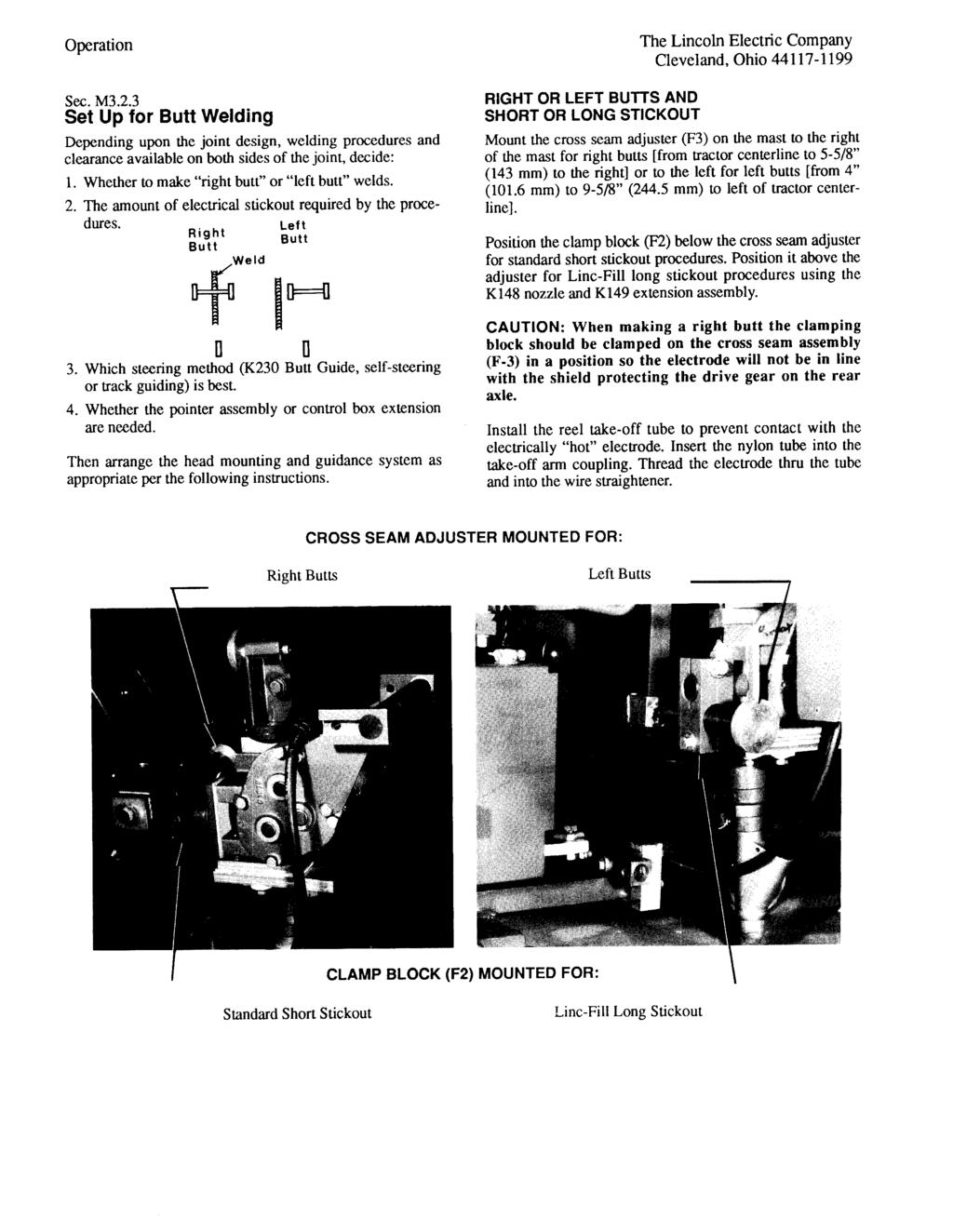
LT-7 Lightweight Tractor
|
|
|
- Silas James
- 6 years ago
- Views:
Transcription

1 Operator s Manual LT-7 Lightweight Tractor For use with machines having Code Numbers: K395-2 Save for future reference Register your machine: Authorized Service and Distributor Locator: Date Purchased Code: (ex: 10859) Serial: (ex: U ) IM10225 Issue Date July-15 Lincoln Global, Inc. All Rights Reserved.
2 THANK YOU FOR SELECTING A QUALITY PRODUCT BY LINCOLN ELEC TRIC. PLEASE EXAMINE CARTON AND EQUIPMENT FOR DAMAGE IMMEDIATELY When this equipment is shipped, title passes to the purchaser upon receipt by the carrier. Consequently, claims for material damaged in shipment must be made by the purchaser against the transportation company at the time the shipment is received. SAFETY DEPENDS ON YOU Lincoln arc welding and cutting equipment is designed and built with safety in mind. However, your overall safety can be increased by proper installation... and thoughtful operation on your part. DO NOT INSTALL, OPERATE OR REPAIR THIS EQUIPMENT WITHOUT READING THIS MANUAL AND THE SAFETY PRECAUTIONS CONTAINED THROUGHOUT. And, most importantly, think before you act and be careful. WARNING This statement appears where the information must be followed exactly to avoid serious personal injury or loss of life. CAUTION This statement appears where the information must be followed to avoid minor personal injury or damage to this equipment. KEEP YOUR HEAD OUT OF THE FUMES. DON T get too close to the arc. Use corrective lenses if necessary to stay a reasonable distance away from the arc. READ and obey the Safety Data Sheet (SDS) and the warning label that appears on all containers of welding materials. USE ENOUGH VENTILATION or exhaust at the arc, or both, to keep the fumes and gases from your breathing zone and the general area. IN A LARGE ROOM OR OUTDOORS, natural ventilation may be adequate if you keep your head out of the fumes (See below). USE NATURAL DRAFTS or fans to keep the fumes away from your face. If you de velop unusual symptoms, see your supervisor. Perhaps the welding atmosphere and ventilation system should be checked. WEAR CORRECT EYE, EAR & BODY PROTECTION PROTECT your eyes and face with welding helmet properly fitted and with proper grade of filter plate (See ANSI Z49.1). PROTECT your body from welding spatter and arc flash with protective clothing including woolen clothing, flame-proof apron and gloves, leather leggings, and high boots. PROTECT others from splatter, flash, and glare with protective screens or barriers. IN SOME AREAS, protection from noise may be appropriate. BE SURE protective equipment is in good condition. Also, wear safety glasses in work area AT ALL TIMES. SPECIAL SITUATIONS DO NOT WELD OR CUT containers or materials which previously had been in contact with hazardous substances unless they are properly cleaned. This is extremely dangerous. DO NOT WELD OR CUT painted or plated parts unless special precautions with ventilation have been taken. They can release highly toxic fumes or gases. Additional precautionary measures PROTECT compressed gas cylinders from excessive heat, mechanical shocks, and arcs; fasten cylinders so they cannot fall. BE SURE cylinders are never grounded or part of an electrical circuit. REMOVE all potential fire hazards from welding area. ALWAYS HAVE FIRE FIGHTING EQUIPMENT READY FOR IMMEDIATE USE AND KNOW HOW TO USE IT. Safety 01 of 04-06/15/2016
3 SAFETY SECTION A: WARNINGS CALIFORNIA PROPOSITION 65 WARNINGS Diesel Engines Diesel engine exhaust and some of its constituents are known to the State of California to cause cancer, birth defects, and other reproductive harm. Gasoline Engines The engine exhaust from this product contains chemicals known to the State of California to cause cancer, birth defects, or other reproductive harm. ARC WELDING CAN BE HAZARDOUS. PROTECT YOURSELF AND OTHERS FROM POSSIBLE SERIOUS INJURY OR DEATH. KEEP CHILDREN AWAY. PACEMAKER WEARERS SHOULD CONSULT WITH THEIR DOCTOR BEFORE OPERATING. Read and understand the following safety highlights. For additional safety information, it is strongly recommended that you purchase a copy of Safety in Welding & Cutting - ANSI Standard Z49.1 from the American Welding Society, P.O. Box , Miami, Florida or CSA Standard W A Free copy of Arc Welding Safety booklet E205 is available from the Lincoln Electric Company, St. Clair Avenue, Cleveland, Ohio BE SURE THAT ALL INSTALLATION, OPERATION, MAINTENANCE AND REPAIR PROCEDURES ARE PERFORMED ONLY BY QUALIFIED INDIVIDUALS. FOR ENGINE POWERED EQUIPMENT. 1.a. Turn the engine off before troubleshooting and maintenance work unless the maintenance work requires it to be running. 1.b. Operate engines in open, well-ventilated areas or vent the engine exhaust fumes outdoors. 1.c. Do not add the fuel near an open flame welding arc or when the engine is running. Stop the engine and allow it to cool before refueling to prevent spilled fuel from vaporizing on contact with hot engine parts and igniting. Do not spill fuel when filling tank. If fuel is spilled, wipe it up and do not start engine until fumes have been eliminated. 1.d. Keep all equipment safety guards, covers and devices in position and in good repair. Keep hands, hair, clothing and tools away from V-belts, gears, fans and all other moving parts when starting, operating or repairing equipment. 1.e. In some cases it may be necessary to remove safety guards to perform required maintenance. Remove guards only when necessary and replace them when the maintenance requiring their removal is complete. Always use the greatest care when working near moving parts. 1.f. Do not put your hands near the engine fan. Do not attempt to override the governor or idler by pushing on the throttle control rods while the engine is running. 1.g. To prevent accidentally starting gasoline engines while turning the engine or welding generator during maintenance work, disconnect the spark plug wires, distributor cap or magneto wire as appropriate. 1.h. To avoid scalding, do not remove the radiator pressure cap when the engine is hot. ELECTRIC AND MAGNETIC FIELDS MAY BE DANGEROUS 2.a. Electric current flowing through any conductor causes localized Electric and Magnetic Fields (EMF). Welding current creates EMF fields around welding cables and welding machines 2.b. EMF fields may interfere with some pacemakers, and welders having a pacemaker should consult their physician before welding. 2.c. Exposure to EMF fields in welding may have other health effects which are now not known. 2.d. All welders should use the following procedures in order to minimize exposure to EMF fields from the welding circuit: 2.d.1. Route the electrode and work cables together - Secure them with tape when possible. 2.d.2. Never coil the electrode lead around your body. 2.d.3. Do not place your body between the electrode and work cables. If the electrode cable is on your right side, the work cable should also be on your right side. 2.d.4. Connect the work cable to the workpiece as close as possible to the area being welded. 2.d.5. Do not work next to welding power source. Safety 02 of 04-06/15/2016
4 SAFETY ELECTRIC SHOCK CAN KILL. 3.a. The electrode and work (or ground) circuits are electrically hot when the welder is on. Do not touch these hot parts with your bare skin or wet clothing. Wear dry, hole-free gloves to insulate hands. 4.a. ARC RAYS CAN BURN. Use a shield with the proper filter and cover plates to protect your eyes from sparks and the rays of the arc when welding or observing open arc welding. Headshield and filter lens should conform to ANSI Z87. I standards. 3.b. Insulate yourself from work and ground using dry insulation. Make certain the insulation is large enough to cover your full area of physical contact with work and ground. In addition to the normal safety precautions, if welding must be performed under electrically hazardous conditions (in damp locations or while wearing wet clothing; on metal structures such as floors, gratings or scaffolds; when in cramped positions such as sitting, kneeling or lying, if there is a high risk of unavoidable or accidental contact with the workpiece or ground) use the following equipment: Semiautomatic DC Constant Voltage (Wire) Welder. DC Manual (Stick) Welder. AC Welder with Reduced Voltage Control. 3.c. In semiautomatic or automatic wire welding, the electrode, electrode reel, welding head, nozzle or semiautomatic welding gun are also electrically hot. 3.d. Always be sure the work cable makes a good electrical connection with the metal being welded. The connection should be as close as possible to the area being welded. 3.e. Ground the work or metal to be welded to a good electrical (earth) ground. 3.f. Maintain the electrode holder, work clamp, welding cable and welding machine in good, safe operating condition. Replace damaged insulation. 3.g. Never dip the electrode in water for cooling. 3.h. Never simultaneously touch electrically hot parts of electrode holders connected to two welders because voltage between the two can be the total of the open circuit voltage of both welders. 3.i. When working above floor level, use a safety belt to protect yourself from a fall should you get a shock. 3.j. Also see It ems 6.c. and 8. 4.b. 4.c. Use suitable clothing made from durable flame-resistant material to protect your skin and that of your helpers from the arc rays. Protect other nearby personnel with suitable, non-flammable screening and/or warn them not to watch the arc nor expose themselves to the arc rays or to hot spatter or metal. FUMES AND GASES CAN BE DANGEROUS. 5.a. Welding may produce fumes and gases hazardous to health. Avoid breathing these fumes and gases. When welding, keep your head out of the fume. Use enough ventilation and/or exhaust at the arc to keep fumes and gases away from the breathing zone. When welding hardfacing (see instructions on container or SDS) or on lead or cadmium plated steel and other metals or coatings which produce highly toxic fumes, keep exposure as low as possible and within applicable OSHA PEL and ACGIH TLV limits using local exhaust or mechanical ventilation unless exposure assessments indicate otherwise. In confined spaces or in some circumstances, outdoors, a respirator may also be required. Additional precautions are also required when welding on galvanized steel. 5. b. The operation of welding fume control equipment is affected by various factors including proper use and positioning of the equipment, maintenance of the equipment and the specific welding procedure and application involved. Worker exposure level should be checked upon installation and periodically thereafter to be certain it is within applicable OSHA PEL and ACGIH TLV limits. 5.c. Do not weld in locations near chlorinated hydrocarbon vapors coming from degreasing, cleaning or spraying operations. The heat and rays of the arc can react with solvent vapors to form phosgene, a highly toxic gas, and other irritating products. 5.d. Shielding gases used for arc welding can displace air and cause injury or death. Always use enough ventilation, especially in confined areas, to insure breathing air is safe. 5.e. Read and understand the manufacturer s instructions for this equipment and the consumables to be used, including the Safety Data Sheet (SDS) and follow your employer s safety practices. SDS forms are available from your welding distributor or from the manufacturer. 5.f. Also see item 1.b. Safety 03 of 04-06/15/2016
5 SAFETY WELDING AND CUTTING SPARKS CAN CAUSE FIRE OR EXPLOSION. 6.a. Remove fire hazards from the welding area. If this is not possible, cover them to prevent the welding sparks from starting a fire. Remember that welding sparks and hot materials from welding can easily go through small cracks and openings to adjacent areas. Avoid welding near hydraulic lines. Have a fire extinguisher readily available. 6.b. Where compressed gases are to be used at the job site, special precautions should be used to prevent hazardous situations. Refer to Safety in Welding and Cutting (ANSI Standard Z49.1) and the operating information for the equipment being used. 6.c. When not welding, make certain no part of the electrode circuit is touching the work or ground. Accidental contact can cause overheating and create a fire hazard. 6.d. Do not heat, cut or weld tanks, drums or containers until the proper steps have been taken to insure that such procedures will not cause flammable or toxic vapors from substances inside. They can cause an explosion even though they have been cleaned. For information, purchase Recommended Safe Practices for the Preparation for Welding and Cutting of Containers and Piping That Have Held Hazardous Substances, AWS F4.1 from the American Welding Society (see address above). 6.e. Vent hollow castings or containers before heating, cutting or welding. They may explode. 6.f. Sparks and spatter are thrown from the welding arc. Wear oil free protective garments such as leather gloves, heavy shirt, cuffless trousers, high shoes and a cap over your hair. Wear ear plugs when welding out of position or in confined places. Always wear safety glasses with side shields when in a welding area. 6.g. Connect the work cable to the work as close to the welding area as practical. Work cables connected to the building framework or other locations away from the welding area increase the possibility of the welding current passing through lifting chains, crane cables or other alternate circuits. This can create fire hazards or overheat lifting chains or cables until they fail. 6.h. Also see item 1.c. CYLINDER MAY EXPLODE IF DAMAGED. 7.a. Use only compressed gas cylinders containing the correct shielding gas for the process used and properly operating regulators designed for the gas and pressure used. All hoses, fittings, etc. should be suitable for the application and maintained in good condition. 7.b. Always keep cylinders in an upright position securely chained to an undercarriage or fixed support. 7.c. Cylinders should be located: Away from areas where they may be struck or subjected to physical damage. A safe distance from arc welding or cutting operations and any other source of heat, sparks, or flame. 7.d. Never allow the electrode, electrode holder or any other electrically hot parts to touch a cylinder. 7.e. Keep your head and face away from the cylinder valve outlet when opening the cylinder valve. 7.f. Valve protection caps should always be in place and hand tight except when the cylinder is in use or connected for use. 7.g. Read and follow the instructions on compressed gas cylinders, associated equipment, and CGA publication P-l, Precautions for Safe Handling of Compressed Gases in Cylinders, available from the Compressed Gas Association, George Carter Way Chantilly, VA FOR ELECTRICALLY POWERED EQUIPMENT. 8.a. Turn off input power using the disconnect switch at the fuse box before working on the equipment. 8.b. Install equipment in accordance with the U.S. National Electrical Code, all local codes and the manufacturer s recommendations. 6.I. 6.j. Read and follow NFPA 51B Standard for Fire Prevention During Welding, Cutting and Other Hot Work, available from NFPA, 1 Batterymarch Park, PO box 9101, Quincy, MA Do not use a welding power source for pipe thawing. 8.c. Ground the equipment in accordance with the U.S. National Electrical Code and the manufacturer s recommendations. Refer to for additional safety information. Safety 04 of 04-06/15/2016
6 LT-7 Lightweight Tractor NOTES
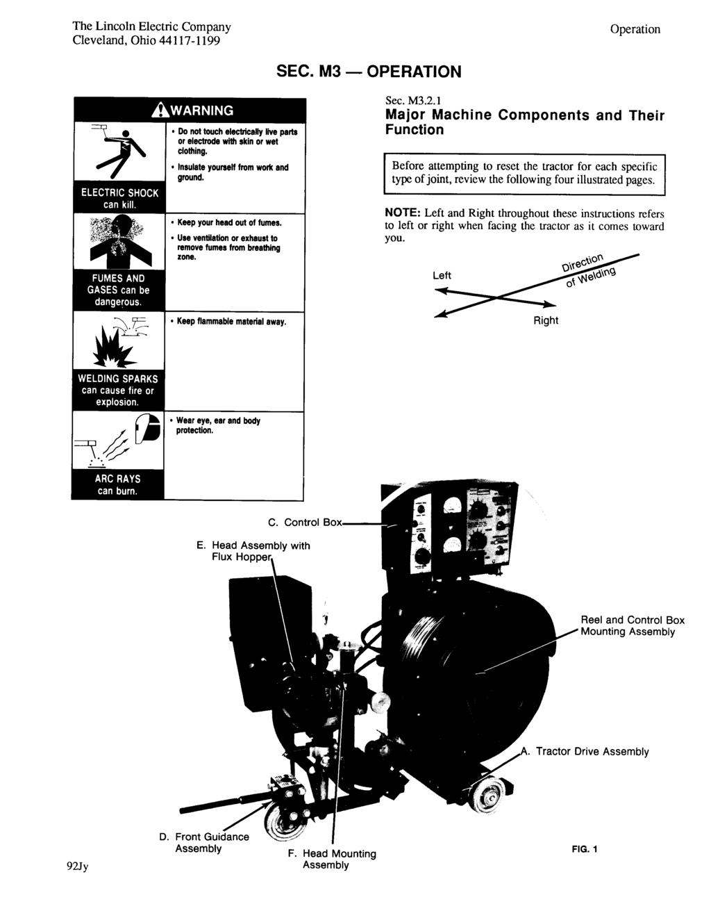
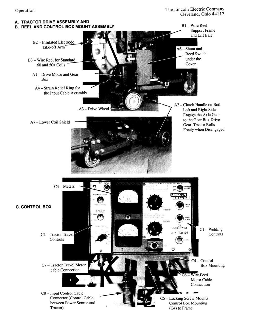
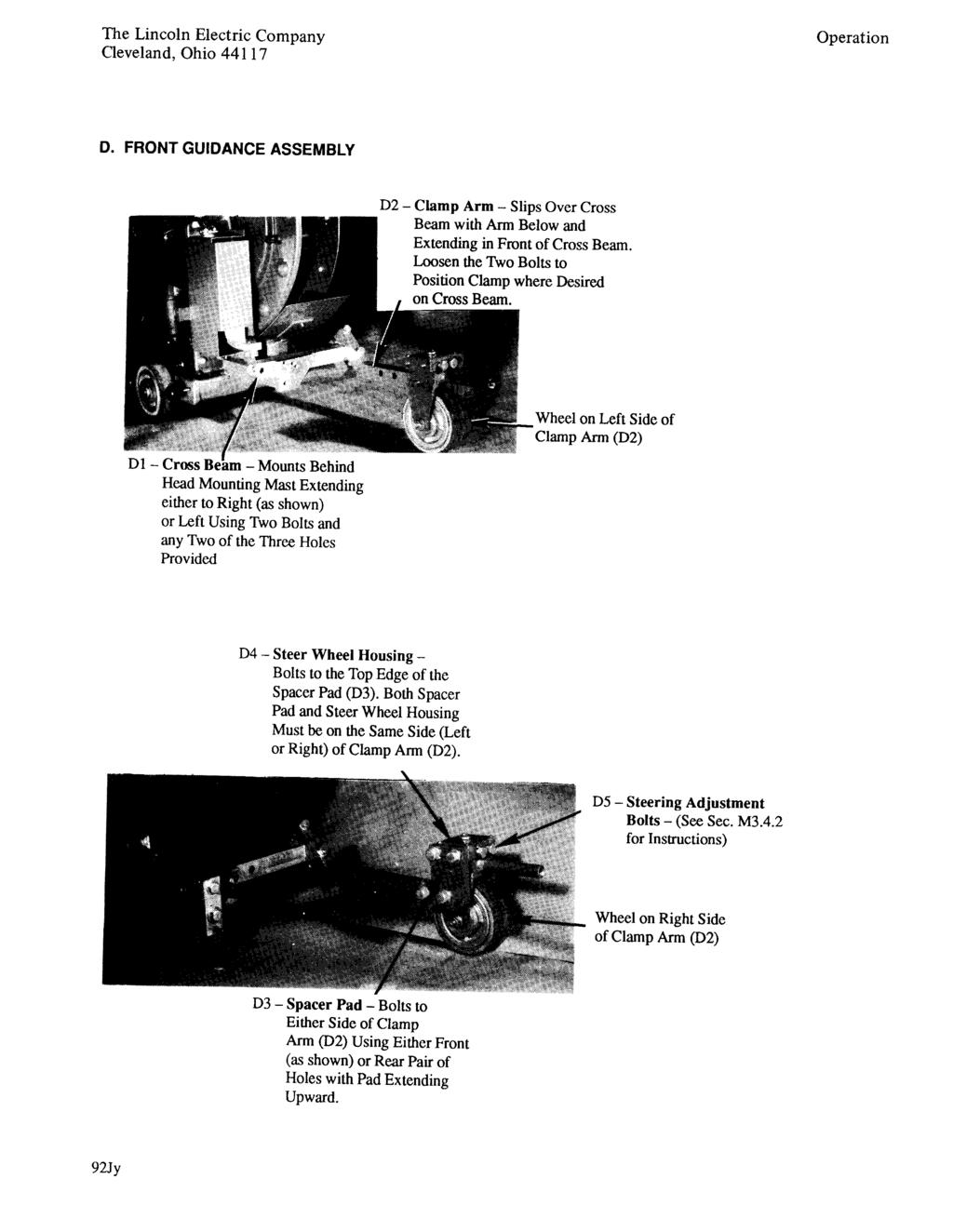
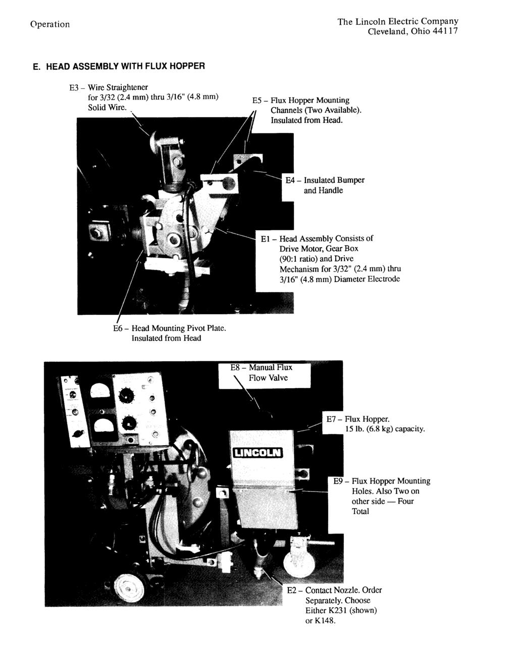
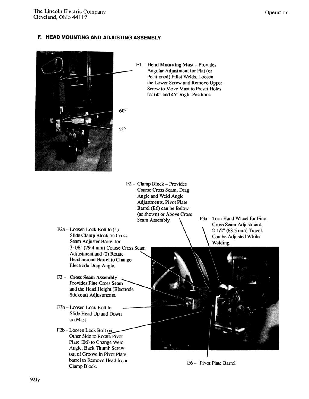
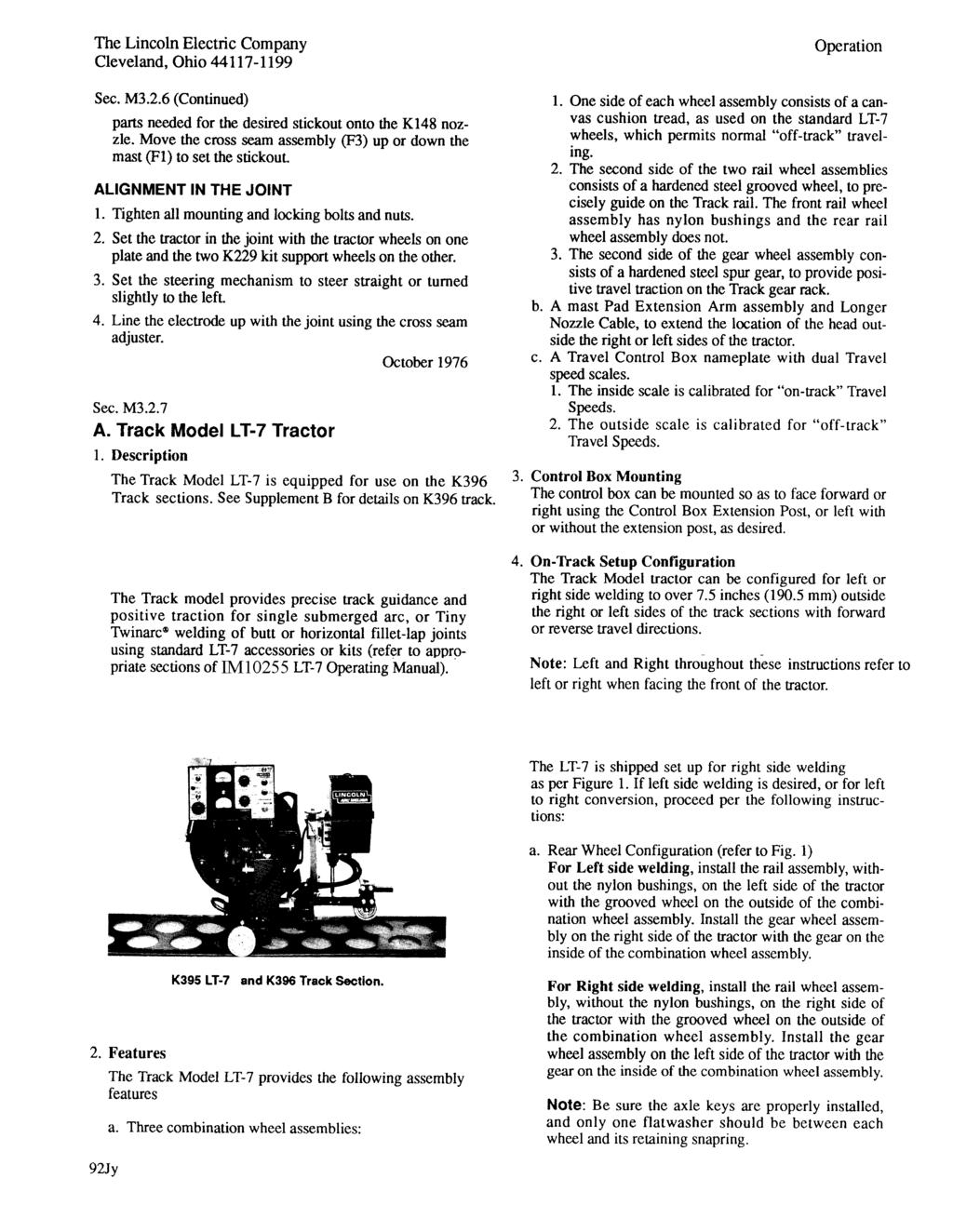
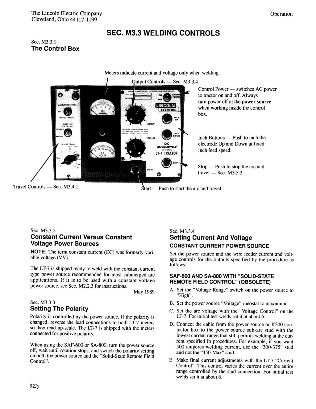
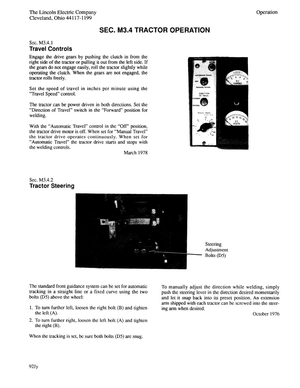
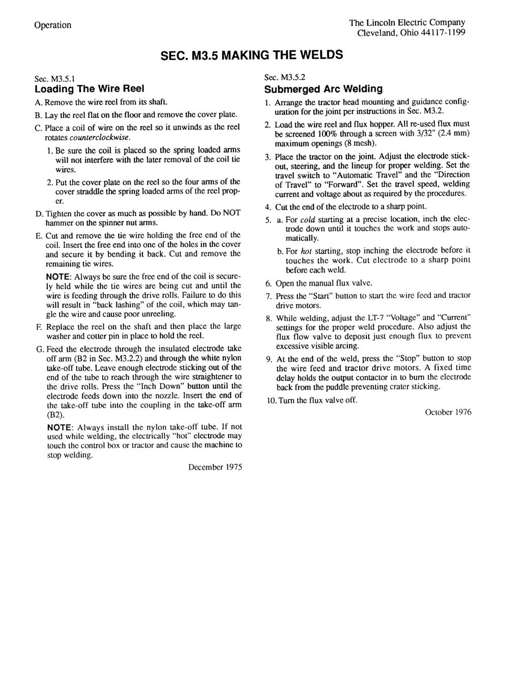
7 Index The Lincoln Electric Company Cleveland, Ohio LT-7 TRACTOR OPERATING MANUAL SEC. M1 - INDEX Index... Sec. Ml Installation... Sec. M2 Mechanical Installation... Sec. M2.2.1 Electrical Installation... Sec. M2.2.3 Connection Diagrams... Sec. M2.2.4 K23 l Contact Nozzle Assembly... Sec. M2.2.6 Kl48 Contact Nozzle and K149 Linc-Fill Long Stickout Extension... Sec. M2.2.7 K277-1 and K277-2 Tiny Twinarc Kits... Sec. M2.2.8 K280 Vertical Lift Adjuster... Sec. M2.2.9 K395 Track Model LT-7... Sec. M K396 Track Sections... Sec. M2.2.1 l Operation... Sec. M3 Major Machine Components and Their Function... Sec. M3.2.1 A. Tractor Drive Assembly B. Reel and Control Box Mount Assembly C. Control Box D. Front Guidance Assembly E. Head Assembly With Flux Hopper F. Head Mounting and Adjusting Assembly Machine Set Up For Butt Welding... Sec. M3.2.3 Machine Set Up For Horizontal Fillet Welding... Sec. M3.2.4 Machine Set Up For Lap Welding... Sec. M3.2.5 Machine Set Up For Fillet Welding... Sec. M3.2.6 Track Model LT-7 Tractor... Sec. M3.2.7 Welding Controls... Sec. M3.3 The Control Box... Sec. M Constant Current vs. Constant Voltage Power Sources... Sec. M3.3.2 Setting the Polarity... Sec. M3.3.3 Setting Current and Voltage (CC Power Source)... Sec. M3.3.4 Setting Current and Voltage (CV Power Source)... Sec. M3.3.5 Tractor Operation... Sec. M3.4 Tractor Controls... Sec. M3.4. l Tractor Steering... Sec. M3.4.2 Making the Welds... Sec. M3.5 Loading the Wire Reel... Sec. M3.5.1 Submerged Arc Welding... Sec. M3.5.2 Maintenance... Sec. M6 Wire Drive Motor and Gear Box... Sec. M6.l. l Drive Rolls and Guide Tubes... Sec. M6.1.2 Contact Nozzle Assembly... Sec. M6. l.3 Wire Straightener... Sec. M6. l.4 Wire Reel Mounting - 50 and 60 Pound Coils... Sec. M6.l.5 Axle Drive Gear... Sec. M6.1.8 Control Box... Sec. M6.2. l Circuit Protection... Sec. M6.2.2 Grounding Lead Protector... Sec. M6.2.3 Part Lists and Wiring Diagrams... Sec. M7 May 1989

8 This equipment is for industrial use only and it is not intended for use in residential locations where the electrical power is provided by the public low-voltage supply system. There can be potential difficulties in residential locations due to conducted as well as radiated radio-frequency disturbances. The EMC or RF classification of this equipment in Class A.
9

10
11
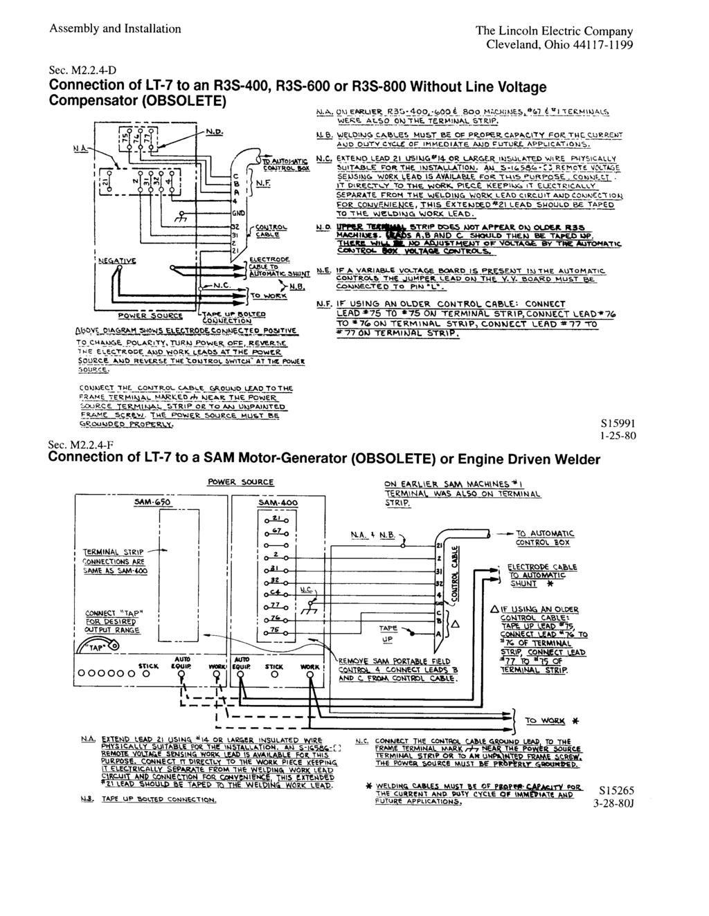
12 Connection of LT-7 to CV-655, DC-600, DC655 and Flextec 650
13
14
15
16
17
18
19
20
21
22
23

24
25

26
27
28
29
30
31
32
33
34
35
36
37

38
39

40
41
42
43
44
45
46
47
48
49
50
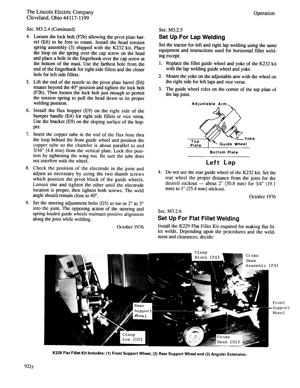
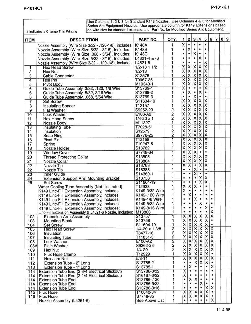
51 P-117-A RETURN TO MAIN INDEX SEC. M7 LT-7 K227 OR K395 LIGHTWEIGHT TRACTOR PARTS LIST Model Index P-117-A General Assembly P-117-C Head Assembly P-117-D Wire Straightener P-117-F Front Wheel Assembly P-117-G K229, K230 & K232 Optional Guide Kits P-117-J Control Box P-117-L Internal Controls Assembly P-117-M Vertical Head Lift Adjuster P-117-O K277-1 and -2 Tiny Twinarc Adapter Kits P-117-P K285 Concentric Flux Cone P-114-J K231 Nozzle Assembly P-101-M K148 Fully Automatic Nozzles and Extensions P-101-K K224 Solid-State Remote Field Control P-114-H K129 Sub-Arc Twinarc P-101-G K281 Wire Straightener P-101-G.2 K396 Track Sections P-117-R Conversion Kit (To convert K227 Tractor to Track Model) Order K
52 P-117-C P-117-C GENERAL ASSEMBLY (ONE OF THREE) A 9 9C 17 9E 9D 9B 9A B
53 P-117-C.1 P-117-C.1 # Indicates a Change This Printing ITEM DESCRIPTION PART NO. QTY Button Head Socket Screw T X 2 Wheel Scraper T X 3 Cross Beam (D1) (Std. Tractor) M X 3 Cross Beam Assembly, Includes: (Track Model Only) S X Mast Pad S X Arm M X 4 Cross Seam Assembly (F3) M X 5 Cam Block Spacer Pad T X 6 Reed Switch Assembly (3CR), Includes: S X Reed Switch S X Energizer M X 7 Shunt M X 8 Cable Strain Relief Ring (A4) (Not Shown) S X 9 Tractor Drive Assembly, Includes: (A1) (Below Code 9100) M X 9 Tractor Drive Assembly, Includes: (A1) (Above Code 9100) M X 9A Drive Motor and Gear Box (Below Code 9100) M ø 1 X 9B Brush and Spring Assembly M B 2 X 9C Brush Cap M C ø 2 X 9A Drive Motor and Gear Box (Above Code 9100) M X 9B Brush and Spring Assembly M15340-B 2 X 9C Brush Cap M15340-C 2 X 9D Pinion Gear S X 9E Roll Pin T X 9F Motor End Cap 1 X 10 Drive Gear Guard M X 11 Frame Assembly (Below Code 7675) L X 11 Frame Assembly (Above Code 7675) L X 12 Reel Side Shield S X 13 Reel Bottom Shield (A7) S X 14 Nozzle Cable (Std. Tractor) M X 14 Nozzle Cable (Track Model Only) M X 15 Mast (F1) (Below Code 8000) S X 15 Vertical Head Lift Adjuster (F1) (Above Code 8000) M X 16 Vertical Head Lift Adjuster Parts Clamp Arm (D2), Includes:Hardware (Not Shown) See P-117-O S X 16A Upper Jaw and Arm M X 16B Lower Jaw S X 17 Front Wheel Assembly (D) (Std. Tractor) M X 17 Front Wheel Assembly (D) (Track Model Only) M X Wheel Assembly Parts See P-117-G 18 Shunt Cover L X 19 Shunt Insulation S X 20 Shunt Shield S X 21 Steering Extension Arm T X ø This part is obsolete and no longer available
54 P-117-C.2 P-117-C.2 General Assembly (TWO OF THREE) B 1A A 17A 11 17B B A11B
55 P-117-C.3 P-117-C.3 # Indicates a Change This Printing ITEM DESCRIPTION PART NO. QTY A Clutch Handle (A2) T X 1B Knob T X 2 Clutch Spring Cam T X 3 Clutch Fork Assembly S X 4 Roll Pin T X 5 Drive Gear Key M X 6 Drive Gear S X 7 Bearing S X 8 Wheel Key M X 9 Axle S X 10 Retaining Ring S X 11 Rear Wheel (A3) (Std. Tractor) S X 11 Gear Wheel Assembly, Includes: (Track Model Only) S X 11A Gear Wheel S X 11B Wheel S X 12A Clutch Handle (A2) T X 12B Knob T X 13 Flux Hopper Assembly, Includes: (E7) M X Flux Flow Valve S X 14 Wire Straightener (E3) & Wire Straightener Parts See P-117-F 1 X 15 Flux Tube and Tip T X 16 Pointer Assembly S X Pointer Clamp for K148 Nozzle (Not Shown) S X 17 Rail Wheel Assembly, Includes: (Track Model Only) S X 17A Rail Wheel S X 17B Wheel S X 18 Bumper Handle Assembly, Includes: M X 19 Handle S X # #
56 P-117-C.4 P-117-C.4 General Assembly Three of Three
57 P-117-C.5 P-117-C.5 # Indicates a Change This Printing Use only the parts marked X in the column under the heading number called for in the model index page. ITEM DESCRIPTION PART NO. QTY Electrode Feed Tube S X 2 Electrode Take-Off Arm S X 3 Control Box (C) See P-117-L 1 X 4 Control Box Support (C4) (Below Code 7675) S X 4 Control Box Support (C4) (Above Code 7675) S X 5 Wire Reel (B3) L X 6 Reel Mount Assembly (B1) (Below Code 7675) M12787 ø 1 X 6 Reel Mount Assembly (B1) (Above Code 7675) M X 7 Reel Top Shield Support S X 8 Reel Top Shield (Below Code 7675) T X 8 Reel Top Shield (Above Code 7675) T X 9 Insulating Washer S X 10 Wire Reel Shaft S X 11 Roll Pin T X 12 Plain Washer S X 13 Insulating Tube T X 14 Control Box Mount Extension S X # ø This part is obsolete and no longer available
58 P-117-D P-117-D HEAD ASSEMBLY 11E B 26 11D 11C 11A A C } B B D 23E 10 23A
59 P-117-D.1 P-117-D.1 # Indicates a Change This Printing ITEM DESCRIPTION PART NO. QTY A Gear Box Assembly, Includes: L X Assembly without Motor L5504-1A 1 X 1B Drive Motor Assembly, Includes: M X Drive Motor NSS 1 X Brush 8 Spring Assembly M X Brush Cap M X Pinion Gear T X Roll Pin T X Groove Pin, Motor to Gear Box T X Socket Head Screw, Motor to Gear Box T X 2 Drive Roll S /16 2 X 3 Sems Screw T X 4 Collar Assembly T X 5 Key M X 6 Nozzle Clip T X 7 Outgoing Guide Tube S /16 1 X 8 Nozzle Mount Pad S X 9 Socket Head Cap Screw T X 10 5/16-18 x 1.00 Hex Head Screw CF X 11A Hex Head Screw 5/16-18 x X 11B Insulating Tube, Pivot Arm Mounting (Code 7429 Only) T ø 2 X 11B Insulating Tube, Pivot Arm Mounting T X 11C Insulating Washers, Pivot Arm Mounting (Code 7429 Only) S X 11C Insulating Washers, Pivot Arm Mounting S X 11D Flat Washer S X 11E Lock Washer E106A-14 2 X 12 Socket Set Screw S X 13 Pivot Pin T X 14 Idle Roll Assembly S X 15 Thread Forming Screw S X 16 Spring T X 17 Hex Nut 5/ X 18 Incoming Guide Tube S /16 1 X 19 Idle Roll Pull Arm S X 20 Straightener Mounting Block T X 21 Idle Roll Arm Bracket T X 22 Flat Washer S X 23A Hex Head Screw 5/16-18 x X 23B Insulating Washer S X 23C Insulating Tube T X 23D Lock Washer E106A-14 2 X 23E Flat Washer S X 24 Fillet-Lap Attachment, Mounting Plate S X 26 Pivot Plate and Arm Assembly (Code 7429 Only) S15220 ø 1 X 26 Pivot Plate and Arm Assembly S X 27 Spacer S X 28 Socket Head Cap Screw T X 29 Insulation T X 30 Insulation, Pivot Arm Mounting (Code 7429 Only) S15217 ø 1 X 30 Insulation, Pivot Arm Mounting S X # ø This part is obsolete and no longer available. NSS - Not sold separately
60 P-117-F P-117-F WIRE STRAIGHTENER M P # Indicates a Change This Printing ITEM DESCRIPTION PART NO. QTY Wire Straightener, Includes All Below: M Roll Pin T Screw Bushing T Slide Screw Assembly S Body Assembly M Wire Guide Wheel M Hex Head Bolt 5/16-18 x Slide Bushing T Flat Washer S Lock Washer E106A Hex Nut 5/ # #
61 P-117-G P-117-G FRONT WHEEL ASSEMBLY # Indicates a Change This Printing ITEM DESCRIPTION PART NO. QTY Front Wheel Assembly, Includes: (Std. Tractor) Front Wheel Assembly, Includes: (Track Model Only) M12669 M X X 1 Hex Head Screw 3/8-16 x X 2 Retaining Ring S X 3 Bearing S X 4 Steerage Cam S X 5 7 Cam Block (Upper) Bearing, Bronze S15163 S X X 8 10 Plain Washer Hex Nut (Not Shown) S / X X 11 Bearing (Std. Tractor Only) S X 12 Sleeve S X 13 Wheel (Std. Tractor) S X 13 Wheel (Track Model Only) Includes: S X 13A Rail Wheel S X 13B 13C Wheel Bearing S17635 S X X Roll Pin Steerage Plunger T T X X 16 Compression Spring T X Set Screw Plunger & Wheel Housing Assembly S S X X 19 Lock Washer (Not Shown) E106A-14 2 X Hex Head Screw (Not Shown) Instruction Plate 5/16-18 x 2.75 S X X 22 Drive Screw S X
62 NOTES
63 P-117-J P-117-J OPTIONAL GUIDES # Indicates a Change This Printing ITEM DESCRIPTION PART NO. QTY Butt Guide Kit, Includes: K230 1 Guide Wheel Bracket S Guide Wheel S Retaining Ring S Flat Fillet Guide Kit, Includes: K229 1 Reel Adapter Bracket M Rear Support Assembly, Includes: S Bracket M Wheel T Front Support Assembly, Includes: S Bracket S Wheel T Horizontal Fillet-Lap Guide Kit, Includes: K232 1 Front Guide Assembly, Includes: M Attachment Arm S Slide Arm and Yoke Pivot S Wing Screw T Fillet Guide Wheel Assembly S Wing Screw T A Wing Nut T B Lap Guide Wheel Assembly S C Wing Screw T Tension Spring and Hook (Not Shown) T Rear Support, Includes: (Not Shown S Arm S Wheel T
64 P-117-L P-117-L CONTROL BOX P K 10P K 26 26A 26B B 23 22P 20 22K 21A
65 P-117-L.1 P-117-L.1 For Codes Below 7900 use Column 1. For Codes 7900 to 9100 use Column 2. For Codes 9100 to use Column 3. For Codes Above use Column 4. # Indicates a Change This Printing ITEM DESCRIPTION PART NO. QTY Complete Control Box Assembly, Includes: (Code 7429 Only) L X Complete Control Box Assembly, Includes: L ø 1 X Complete Control Box Assembly, Includes: (Std. Tractor) L X Complete Control Box Assembly, Includes: (Track Model Only) L X Complete Control Box Assembly, Includes: (Std. Tractor) L X X Complete Control Box Assembly, Includes: (Track Model Only) L X X A Front Panel Assembly, Includes: M12698 ø 1 X A Front Panel Assembly, Includes: M X X X 1 Panel S X X X X 2 Voltmeter M X X X 2 Voltmeter M X 3 Circuit Breaker T X X X X 4 Ammeter M X X X 4 Ammeter M X 5-P Potentiometer T X X X X 5-K Knob T X X X X 5-1 Insulation T X X X X 6 Control Power Switch T X X X X 7 Inch Switch T X X X X 8 Stop Switch T X X X X 9 Start Switch T X X X X 10-P Potentiometer T X X X X 10-K Knob T X X X X 10-1 Insulation T X X X X 11 Nameplate - VV L ø 1 X X X X 11 Nameplate - CV (Mounts under VV Nameplate) L X X X B Travel Control Box Assembly, Includes: M X B Travel Control Box Assembly, Includes: (Std. Tractor) M X X X Travel Control Box Assembly, Includes: (Track Model Only) M X X X 20 Box S X 20 Box S X X X 21 Nameplate (Std. Tractor) M X 21 Nameplate (Std. Tractor) M X X X 21 Nameplate (Track Model Only) M X X X Resistor (Not Illustrated) S X X X X 22-P Travel Speed Potentiometer T X X X X 22-K Knob T X X X X 23 Direction of Travel Switch T X 23 Direction of Travel Switch T X X X 24 Travel Switch T X X X X 25 Circuit Breaker T X X X X 26 Travel Box Cover S X 26 Travel Box Cover S X X X Travel P.C. Board (Not Illustrated) Includes: L5302 ø 1 X Travel P.C. Board (Not Illustrated) Includes: L X Travel P.C. Board (Not Illustrated) Includes: L X X Fuse, 1/2 Amp Slo-Blo T X X Travel P.C. Board Insulation T X Travel P.C. Board Insulation T X X X C Internal Control Box Assembly See P-117-M 1 X X X X ø This part is obsolete and no longer available
66 P-117-M P-117-M INTERNAL CONTROLS ASSEMBLY C 18B 18A 18E 18D B A # Indicates a Change This Printing For Codes Below 7900 use Column 1. For Codes Above 7900 use Column 2. ITEM DESCRIPTION PART NO. QTY C C Internal Control Box Assembly, Includes: (Code 7429 Only) Internal Control Box Assembly, Includes: L5291 L X X C Internal Control Box Assembly, Includes: L X 1 Control Box M X 1 Control Box M X 2 Resistor, 2 OHM S X X 4 Reed Switch Assembly, (4CR) Includes: T X X Reed Switch S X X 5 Terminal Strip S X X Number Plate T X X 6 Resistor, 250 OHM S X X 9 Control P.C. Board, Includes: (Code 7429 Only) L X 9 Control P.C. Board Includes: L X X 9A Fuse, 1/2 Amp Slo-Blo T X X 9B Fuse, 2/10 Amp T X X 9-I Control P.C. Board Insulation (Not Shown) T X X 11 Relay, (1 CR and 2 CR) S X X 14 Auxiliary Power outlet T X X 18 Inner Panel Assembly, Includes: S X 18 Inner Panel Assembly, Includes: S X 18A Panel S X X 18B Variable Voltage P.C. Board L (Note A) 1 X X 18C Variable Voltage P.C. Board Insulation T X X 18D Logic P.C. Board L X 18D Logic P.C. Board L X 18E Logic P.C. Board Insulation T X X Insulation (Mounts Under Lead Clamp) (Not Shown) T X X # # # Note A: L5394 may be used
67 P-117-O P-117-O K280 VERTICAL HEAD LIFT ADJUSTER (Standard Equipment on LT-7 Tractors Above Code 7948) 6C 6A 6B B 13B 13A 9A 8 { 12 1 { 9B 9A B 13A # Indicates a Change This Printing ITEM DESCRIPTION PART NO. QTY Vertical Head Lift Adjuster, Includes All Below: M X 1 Mast Core S X 2 Barrel and Shaft Assembly S X 3 Bearing M X 4 Mast M X 5 Roll Pin T X 6A Adjusting Knob S X 6B Lock Washer E106A-14 1 X 6C 5/16-18 HN CF X 7 Mounting Plate S X 8 Pressure Plate T X 9A Bow Washer T X 9B Socket Head Cap Screw T X 10 Torx Button Head Screw S X 11 Slide Pad S X 12 #8-32 x 1.00 Slotted Flat Head Screw CF X 13A 3/8-16 x 2.00 HHCS CF X 13B Lock Washer T X 14 Pressure Slide T X 15 Retaining Ring S X 16 T Locking Screw T X
68 P-117-P P-117-P K277-1 AND -2 TINY TWINARC ADAPTER KITS
69 P-117-P.1 P-117-P.1 # Indicates a Change This Printing ITEM DESCRIPTION PART NO. QTY Reel Adapter (1) M Front Stabilizer Wheel Attachment S Rear Wheel Support Arm S Front Support Wheel (45 Flat Fillet) S Rear Support Wheel (Flat Fillet) (1) S Travel Motor Extension Cable (1) S Flux Tube T Hose Clamp T Wire Guide Tube (5 Ft. Length) S Nozzle Assembly, Includes Items 10 & 11 M Nozzle Body S Nozzle Collar S Contact Tip (5/64) (Note A) T / Contact Tip (3/32) T / Tip Holder, Includes: S Nozzle Insert T Guide Tube (5/64 & 3/32) T / Idle Roll Arm S Drive Roll (Outside) S Drive Roll (Center) S Outgoing Guide Tube S Incoming Guide Tube (Not Illustrated) S Wire Guide Support (Not Illustrated) T Head Spring Extender T Twin Reel Mounting Assembly L Wire Reel L Slide Bushing (Not Illustrated) S Note A: When tip life is limited by tip being fused over, the use of T /64 tips may result in lower overall cost. (1) The K277-1 Kit contains all items except 1, 4, 5 and 6. The K277-2 Kit contains all items shown
70
71
72
73 P-101-M.1 P-101-M.1 # Indicates a Change This Printing Use only the parts marked X in the column under the heading number called for in the model index page. ITEM DESCRIPTION PART NO. QTY Nozzle Assembly, Includes Items 110 thru 125 as appropriate for wire size specified K231* 1 X Nozzle Assembly, for LT34 ONLY, Includes Items 110, 111, 118, 121 and 122; Order Items 119, 120, 123, 124 and 125 separately for the desired wire size M X 110 Nozzle Insulator S X X 111 Nozzle Body S X X 111A Roll Pin T X X 113A Cone Body Assembly, Includes: M X 113B Flux Cone Plug S X 113C Roll Pin T X 114 Retaining Nut S X 115 Flux Cone T X 116 Locking Ferrule T X 117 Thumb Screw T X 118 Special Socket Head Screw T X 119 Rubber Flux Tube (Not Shown) T X 119 Rubber Flux Tube, LT34 Only (Not Shown) T X 120 Steel Flux Tube (Not Shown) T X 120 Steel Flux Tube, LT34 Only (Not Shown) S X 121 Hex Head Screw - Lead to Nozzle 1/2-13 x X X 122 Hex Nut - Lead to Nozzle 1/ X X 123 Contact Tip - 7/32 Wire Size S /32 1 X X 123 Contact Tip - 3/16 Wire size S /16 1 X X 123 Contact Tip - 5/32 Wire Size S /32 1 X X 123 Contact Tip - 1/8 Wire Size S /8 1 X X 123 Contact Tip - 3/32 Wire Size; (3/8-24 Thread) Old Style S8087-3/32 1 X X 123 Contact Tip - 3/32 Wire Size; (5/16-18 Thread) T /32 1 X X 123 Contact Tip - 5/64 Wire Size; (3/8-24 Thread) Old Style S8087-5/64 1 X X 123 Contact Tip - 5/64 Wire Size; (5/16-18 Thread) See Note 1 T /64 1 X X 124 Adapter for 3/32 and 5/64 S8087 Tips (With 3/8-24 Female Thread) See Note 2 1 X X 124 Adapter for 3/32 and 5/64 T14050 Tips (With 5/16-18 Female Thread) S X X 125 Nozzle Insert for 3/32 and 5/64 Wire (For NA) S /32 1 X 125 Nozzle Insert for 5/64 Wire (For LAF & LT) S /32 1 X X Mounting Clip (For Mounting Nozzle on LAF2) T10714 ø 2 X Nozzle Extension (5.38 long) (For 3/32 & Larger Wire) S12003 As Req d X # * Specify Wire Size Note 1 When tip life is limited by tip being fused over, the use of T /64 Tips may result in a lower overall cost. Note 2 This adapter is no longer available, order Adapter S16844 and the appropriate T14050 Tips or T /64 Tip
74
75
76 P-114-H P-114-H K224 SOLID-STATE REMOTE FIELD CONTROL (DISCONTINUED) L Q # Indicates a Change This Printing ITEM DESCRIPTION PART NO. QTY Solid State Remote Field Control, Includes: K Top Door M Terminal Strip S Number Plate T Capacitor S Auto Transformer M12702 ø 1 6 Box Assembly M12706 ø 1 7 Transformer S15257 ø 1 8 Capacitor T Nameplate M Polarity Switch S13417 ø 1 11 Fuse Holder S Fuse T Capacitor S Diode T SCR and Heat Sink M13342 ø 1 15 Control P.C. Board (Code 7359 Only) L Control P.C. Board (Code 7683 & Above) L Caution Decal T Choke S Resistor (Code 7742 & Above) T F 1 K224 Mounting Angles S & 1 ea S13709 # ø This part is obsolete and no longer available
77
78
79
80
81
82
83
84
85
86 LT-7 Lightweight Tractor NOTES
87 LT-7 Lightweight Tractor NOTES
88 Customer assistance PoliCy The business of The Lincoln Electric Company is manufacturing and selling high quality welding equipment, consumables, and cutting equipment. Our challenge is to meet the needs of our customers and to exceed their expectations. On occasion, purchasers may ask Lincoln Electric for advice or information about their use of our products. We respond to our customers based on the best information in our possession at that time. Lincoln Electric is not in a position to warrant or guarantee such advice, and assumes no liability, with respect to such information or advice. We expressly disclaim any warranty of any kind, including any warranty of fitness for any customer s particular purpose, with respect to such information or advice. As a matter of practical consideration, we also cannot assume any responsibility for updating or correcting any such information or advice once it has been given, nor does the provision of information or advice create, expand or alter any warranty with respect to the sale of our products. Lincoln Electric is a responsive manufacturer, but the selection and use of specific products sold by Lincoln Electric is solely within the control of, and remains the sole responsibility of the customer. Many variables beyond the control of Lincoln Electric affect the results obtained in applying these types of fabrication methods and service requirements. Subject to Change This information is accurate to the best of our knowledge at the time of printing. Please refer to for any updated information.
NA-5S. Operator s Manual. IM305-C Issue D ate 10-Sep Lincoln Global, Inc. All Rights Reserved.
 Operator s Manual NA-5S For use with machines having Code Numbers: 8203; 8204; 8205; 8206; 8207; 8208; 8209; 8400; 8464; 8465; 8466; 8467; 8468; 8469; 8470; 8471; 8472; 8473; 8474; 8475; 8476; 8477; 8547;
Stick/Mig Capability Welding Excellence Modular Construction Environment Protected 2,000 Watt AC Power for Tools
 E300 3+2 Electric Welder Service Manual Stick/Mig Capability Welding Excellence Modular Construction Environment Protected 2,000 Watt AC Power for Tools SVM_E300 3+2 SAFETY Arc Welding Safety Precautions
MAGNUM & MAGNUM PRO CURVE 300 & 400 GMA GUN and CABLE ASSEMBLY
 Operator s Manual MAGNUM & MAGNUM PRO CURVE 300 & 400 GMA GUN and CABLE ASSEMBLY Magnum For use with models: K470-[ ] K1802-1 K471-[ ] K2286-1 K541-[ ] K2951-[ ] K2952-[ ] K3055-[ ] Magnum PRO Curve Magnum
Magnum PRO. Guns. Operator s Manual. IM10009-C Issue D ate Dec-15 Lincoln Global, Inc. All Rights Reserved.
 Operator s Manual Magnum PRO Guns For use with machines having Code Numbers: 250 / 350 / 450 / 550 K2651-, K2652-, K2653-, and K2655- Magnum PRO 450 gun meets the following specification(s): IEC 60974-7:2013
LT-7 TRACTOR TROUBLESHOOTING
 TROUBLESHOOTING IM279-TS JUNE 1995 Safety Depends on You Lincoln arc welding and cutting equipment is designed and built with safety in mind. However, your overall safety can be increased by proper installation...
Operator s Manual Model AC300 ARC Welder
 Operator s Manual Model AC300 ARC Welder WARNING: Do not assemble, install, or operate this equipment without reading ALL of this manual and the safety precautions and warnings illustrated in this manual.
THE LINCOLN ELECTRIC COMPANY
 OPERATOR S MANUAL IM3050 04/2015 REV06 ENGLISH THE LINCOLN ELECTRIC COMPANY 22801 St. Clair Avenue Cleveland, OH 44117-1199 U.S.A. Phone: +1.216.481.8100 www.lincolnelectric.com English I English THANKS!
OWNER S MANUAL. Affordable Tools Achieve More. MIG140. Visit Our Website at:
 Affordable Tools Achieve More Visit Our Website at: www.uwelding.com MIG140 OWNER S MANUAL Carefully read the operation manual prior to using, installing and maintaining the electric welding machine IMPORTANT
THANK YOU FOR SELECTING A QUALITY PRODUCT BY LINCOLN ELECTRIC.
 THANK YOU FOR SELECTING A QUALITY PRODUCT BY LINCOLN ELECTRIC. PLEASE EXAMINE CARTON AND EQUIPMENT FOR DAMAGE IMMEDIATELY When this equipment is shipped, title passes to the purchaser upon receipt by the
TURNING ROLLS 00338OG WARNINGS, SAFEGUARDS & OPERATING INSTRUCTIONS
 TURNING ROLLS 00338OG091207 WARNINGS, SAFEGUARDS & OPERATING INSTRUCTIONS Warnings and Safeguards for Welding and Cutting Operations IMPORTANT - Protect yourself and others! Remember that safety depends
TCV400. Operator s Manual. IM10063-B Issue D ate Jul-17 Lincoln Global, Inc. All Rights Reserved.
 Operator s Manual For use with machines having Code Numbers: 11727, 11838 Save for future reference Register your machine: www.lincolnelectric.com/register Authorized Service and Distributor Locator: www.lincolnelectric.com/locator
INVERTER AIR PLASMA CUTTING MACHINE
 INVERTER AIR PLASMA CUTTING MACHINE OPERATION MANUAL DO NOT INSTALL, OPERATE OR MAINTAIN THIS MACHINE WITHOUT READING THIS MANUAL AND PLEASE ALWAYS THINK BEFORE YOU ACT. www.hyundaiwelding.com TECHNICAL
Paralleling Arc Welding Power Sources
 004 859A 2005 10 Paralleling Arc Welding Power Sources Visit our website at www.millerwelds.com SECTION 1 SAFETY PRECAUTIONS - READ BEFORE USING Warning: Protect yourself and others from injury read and
LOTOS MIG175 MIG Welder
 LOTOS MIG175 MIG Welder TABLE OF CONTENTS SAFETY...... 3 SPECIFICATIONS... 8 General Description...8 What s Included.....8 Power Supply Ratings.....9 Machine Rear..10 Front Control Panel.10 Side Components...11
ZIPLINE BOOM PACKAGE. Operator s Manual. IM10184 Issue D ated Dec- 13 Lincoln Global, Inc. All Rights Reserved.
 Operator s Manual ZIPLINE BOOM PACKAGE For use with machines having Code Numbers: K4047-XX, K4048-XX Save for future reference Register your machine: www.lincolnelectric.com/register Authorized Service
OPERATION INSTRUCTIONS
 www.r-techwelding.co.uk Email: sales@r-techwelding.co.uk Tel: 01452 733933 Fax: 01452 733939 ProArc 175 INVERTER ARC WELDER OPERATION INSTRUCTIONS Version 2017-10 2 3 Thank you for selecting the R-Tech
MIG Welders. Operator s Manual Model 135WFG Wire Feed Welder
 Operator s Manual Model 135WFG Wire Feed Welder MIG Welders WARNING: Do not assemble, install, or operate this equipment without reading ALL of this manual and the safety precautions and warnings illustrated
COOL ARC 35. Operator s Manual. IM959 Issue D ate Oct- 13 Lincoln Global, Inc. All Rights Reserved.
 Operator s Manual COOL ARC 35 For use with machines having Code Numbers: 11427 Save for future reference Register your machine: www.lincolnelectric.com/register Authorized Service and Distributor Locator:
For use with machine Code POWERPLUS II 350 K POWERPLUS II 500 K
 IM7003-5 Otc, 2009 Rev. 1 POWERPLUS Ⅱ 350/500 For use with machine Code POWERPLUS II 350 K32063-1 POWERPLUS II 500 K32064-1 Safety Depends on You Lincoln arc welding and cutting equipment is designed and
MMA 160S ARC/MMA WELDER OPERATION INSTRUCTIONS
 www.r-techwelding.co.uk MMA 160S ARC/MMA WELDER OPERATION INSTRUCTIONS 2 Thank you for selecting the R-Tech MMA160S Inverter Arc Welder. The MMA160S has many benefits over traditional Arc welders, including
OWNER S MANUAL. Affordable Tools Achieve More. LT3500. Visit Our Website at:
 Affordable Tools Achieve More Visit Our Website at: www.uwelding.com @lotostech LT3500 OWNER S MANUAL Carefully read the operation manual prior to using, Installing and maintaining the electric welding
LN-25 PRO. Operator s Manual. IM10076 Issue D ate Mar-18 Lincoln Global, Inc. All Rights Reserved.
 Operator s Manual LN-25 PRO For use with machines having Code Numbers: 11746, 11747 Save for future reference Date Purchased Code: (ex: 10859) Register your machine: www.lincolnelectric.com/register Authorized
IDEALARC DC Operator s Manual. IM10214-A Issue D ate Oct-18 Lincoln Global, Inc. All Rights Reserved.
 Operator s Manual IDEALARC DC-500 For use with machines having Code Numbers: 2479 Save for future reference Date Purchased Code: (ex: 0859) Register your machine: www.lincolnelectric.com/register Authorized
Inverter Welding System
 POWER WAVE 455/STT AND POWER FEED 10 DUAL Inverter Welding System NEW! POWER WAVE 455/STT AND POWER FEED 10 DUAL ADVANTAGE LINCOLN HIGHEST PERFORMANCE SYSTEM Superior STT, pulsed GMAW and FCAW welding
RANGER 250 GXT (AU)Model
Model") Operator s Manual RANGER 250 GXT (AU)Model For use with machines having Code Numbers: 11689, 11741, 11796, 11803, 12099, 12194, 12205 Save for future reference Date Purchased Code: (ex: 10859) Register
Operator s Manual RANGER 250 GXT (AU)Model For use with machines having Code Numbers: 11689, 11741, 11796, 11803, 12099, 12194, 12205 Save for future reference Date Purchased Code: (ex: 10859) Register
Idealarc DC-600. Operator s Manual. IM642-E Issue D ate Oct-17 Lincoln Global, Inc. All Rights Reserved.
 Operator s Manual Idealarc DC-600 For use with machines having Code Numbers: 10588; 10589; 10590; 10591; 10592; 10593; 10594; 10595; 10596; 10639; 10640; 10641; 10700; 10701; 11071; 11072; 11129; 11130;
X-Tractor 1GC. Operator s Manual. IM576-B Issue D ate Apr-14 Lincoln Global, Inc. All Rights Reserved.
 Operator s Manual X-Tractor GC Save for future reference Register your machine: www.lincolnelectric.com/register Authorized Service and Distributor Locator: www.lincolnelectric.com/locator Date Purchased
MMWP125I OWNER S MANUAL
 MMWP125I OWNER S MANUAL 1/2017 WARNING: Read carefully and understand all ASSEMBLY AND OPERATION INSTRUCTIONS before operating. Failure to follow the safety rules and other basic safety precautions may
MPPC40DVI OWNER S MANUAL
 MPPC40DVI OWNER S MANUAL 4/2017 WARNING: Read carefully and understand all ASSEMBLY AND OPERATION INSTRUCTIONS before operating. Failure to follow the safety rules and other basic safety precautions may
For use with machine Code POWERPLUS II 350 K / POWERPLUS II 500 K / 76097
 IM7003-1 April, 2011 Rev. 3 POWERPLUS Ⅱ 350/500 For use with machine Code POWERPLUS II 350 K60039-1 / 76095 POWERPLUS II 500 K60040-1 / 76097 Safety Depends on You Lincoln arc welding and cutting equipment
PRO Thru the Arm Robotic Torch - for AutoDrive S
 Operator s Manual Magnum PRO Thru the Arm Robotic Torch - for AutoDrive S Save for future reference Register your machine: www.lincolnelectric.com/registration Authorized Service and Distributor Locator:
Auto-Reamer. 2100E2 Nozzle Cleaning Station. Operating Manual and Parts List. January 2018 v18.1
 Auto-Reamer 2100E2 Nozzle Cleaning Station Operating Manual and Parts List 2100E2 w/ WC-95E DO NOT INSTALL, OPERATE, OR REPAIR THIS EQUIPMENT WITHOUT READING THIS OPERATING MANUAL MADE IN USA January 2018
DIGI-CUT 40PFC MV. Part No. 9030H OPERATOR S MANUAL
 DIGI-CUT 40PFC MV Part No. 9030H OPERATOR S MANUAL IMPORTANT Read this Owner s Manual completely before attempting to use this equipment. Save this manual and keep it handy for quick reference. Pay particular
QUATRO 450 OPERATOR S MANUAL
 QUATRO 450 OPERATOR S MANUAL IMPORTANT DO NOT INSTALL, OPERATE OR REPAIR THIS EQUIPMENT WITHOUT READING THIS MANUAL AND THE SAFETY SECTION CONTAINED INSIDE THIS MANUAL STARWELD WELDING SOLUTIONS WEBSITE:
POWER MIG (140, 180 MODELS)
") Operator s Manual POWER MIG (140, 180 MODELS) For use with machines having Code Numbers: 11254, 11255, 11256, 11257 and 11444 LINCOLN ELECTRIC Save for future reference Register your machine: www.lincolnelectric.com/register
Operator s Manual POWER MIG (140, 180 MODELS) For use with machines having Code Numbers: 11254, 11255, 11256, 11257 and 11444 LINCOLN ELECTRIC Save for future reference Register your machine: www.lincolnelectric.com/register
MMW220PC OWNER S MANUAL
 MMW220PC OWNER S MANUAL 12/2015 WARNING: Read carefully and understand all ASSEMBLY AND OPERATION INSTRUCTIONS before operating. Failure to follow the safety rules and other basic safety precautions may
Description. Order TECHNICAL SPECIFICATIONS
 SEMIAUTOMATIC WIRE FEEDERS Semiautomatic, Constant Speed Wire Feeders The are semiautomatic constant speed wire feeders that provide dependable performance and reliable operation, making them ideal for
IDEALARC DC Operator s Manual. IM10212 Issue D ate Sept-15 Lincoln Global, Inc. All Rights Reserved.
 Operator s Manual IDEALARC DC-000 For use with machines having Code Numbers: 80 Save for future reference Date Purchased Code: (ex: 0859) Register your machine: www.lincolnelectric.com/register Authorized
AutoDrive 4R220. Operator s Manual. IM945-C Issue D ate Oct-14 Lincoln Global, Inc. All Rights Reserved.
 Operator s Manual AutoDrive 4R220 For use with machines having Code Numbers: 455, 882, 956, 2273 Save for future reference Register your machine: www.lincolnelectric.com/register Authorized Service and
PARTS LIST FOR LN-25 LN-25
 P-374 P-374 PARTS LIST FOR 200 250 300 350 400 450 500 550 600 650 700 100 150 50 IN IN/MIN WIRE FEED MORE T13086-99 1. 5. 4. 3. 2. IN/MIN. USED. cross. 35 31 23 25 27 29 15 17 19 21 P-374-A P-374-A ILLUSTRATION
Loose Parts Note: Determine the left and right sides of the machine from the normal operating position.
 Brake Kit Dingo TX 0 & Compact Utility Loader Part No. 0 0 & 0 Loose Parts Note: Determine the left and right sides of the machine from the normal operating position. Description Qty. Use Drive wheel Brake
PC40 INVERTER PLASMA CUTTER 230V 40A SUM OWNER S MANUAL
 PC40 INVERTER PLASMA CUTTER 230V 40A SUM-900990 OWNER S MANUAL WARNING: Read carefully and understand all ASSEMBLY AND OPERATION INSTRUCTIONS before operating. Failure to follow the safety rules and other
MAXSA 22 & 29 WIRE DRIVE
 Operator s Manual MAXSA 22 & 29 WIRE DRIVE For use with machines having Code Numbers: 11615, 11616, 11815, 11816 Save for future reference Register your machine: www.lincolnelectric.com/register Authorized
Quick Draw Spool Gun OWNER S MANUAL
 Quick Draw Spool Gun OWNER S MANUAL WARNING: Read carefully and understand all ASSEMBLY AND OPERATION INSTRUCTIONS before operating. Failure to follow the safety rules and other basic safety precautions
MPPC60I OWNER S MANUAL
 MPPC60I OWNER S MANUAL 4/2017 WARNING: Read carefully and understand all ASSEMBLY AND OPERATION INSTRUCTIONS before operating. Failure to follow the safety rules and other basic safety precautions may
LF-72 and LF-74 Wire Feeders
 SEMIAUTOMATIC WIRE FEEDERS LF-72 and LF-74 Wire Feeders 2-Roll or 4-Roll Heavy Duty Industrial Feeders Designed for MIG and cored wire welding in job shop and manufacturing environments, the rugged LF-72
MULTI-PROCESS POWER FOR HEAVY DUTY APPLICATIONS
 FLEXTEC 650X MULTI-PROCESS POWER FOR HEAVY DUTY APPLICATIONS Shown: K3425-1 SIMPLE. RELIABLE. FLEXIBLE. This multi-process welder delivers up to 815 amps of welding power for a variety of applications,
Mega Force 140i MP. Operator s Manual. IM10462 Issue D ate Apr-18 Lincoln Global, Inc. All Rights Reserved.
 Operator s Manual Mega Force 140i MP For use with Code Numbers: 12769 Save for future reference Date Purchased Code: (ex: 10859) Register your machine: www.lincolnelectric.com/register Authorized Service
OPERATION MANUAL MODELS TWE-250 TWE-321 TWE-375 TRU WELD EQUIPMENT COMPANY 6400 N. HONEYTOWN ROAD SMITHVILLE, OHIO (330)
") OPERATION MANUAL MODELS TWE-250 TWE-321 TWE-375 TRU WELD EQUIPMENT COMPANY 6400 N. HONEYTOWN ROAD SMITHVILLE, OHIO 44677 (330) 669 2773 CONTENTS Section Description Pages 1 Introduction 3 2 External Features
OPERATION MANUAL MODELS TWE-250 TWE-321 TWE-375 TRU WELD EQUIPMENT COMPANY 6400 N. HONEYTOWN ROAD SMITHVILLE, OHIO 44677 (330) 669 2773 CONTENTS Section Description Pages 1 Introduction 3 2 External Features
ARC 1850 LIST OF FIGURES
 PAGE 1.0 INTRODUCTION... 1 2.0 WARRANTY... 1 3.0 UNPACKING YOUR UNIT... 1 4.0 SUGGESTED SAFETY PRECAUTIONS...... 1 4.1 PERSONAL SAFETY PRECAUTIONS. 1 4.2 POWER SUPPLY SAFETY PRECAUTIONS.. 2 5.0 GENERAL
OPERATION MANUAL MODELS TWE-250 TWE-321 TWE-375 TRU WELD EQUIPMENT COMPANY 6400 N. HONEYTOWN ROAD SMITHVILLE, OHIO (330)
") OPERATION MANUAL MODELS TWE-250 TWE-321 TWE-375 TRU WELD EQUIPMENT COMPANY 6400 N. HONEYTOWN ROAD SMITHVILLE, OHIO 44677 (330) 669 2773 Version 1.3 Date 10/20/2010 TRU WELD EQUIPMENT LIMITED WARRANTY All
OPERATION MANUAL MODELS TWE-250 TWE-321 TWE-375 TRU WELD EQUIPMENT COMPANY 6400 N. HONEYTOWN ROAD SMITHVILLE, OHIO 44677 (330) 669 2773 Version 1.3 Date 10/20/2010 TRU WELD EQUIPMENT LIMITED WARRANTY All
OPERATING MANUAL IDEALARC DC-600
 IMA 607A December 2005 OPERATING MANUAL IDEALARC DC-600 SAFETY DEPENDS ON YOU Lincoln Electric welders are designed and built with safety in mind. However, your overall safety can be increased by proper
SAE-500 Severe Duty ENGINE-DRIVEN WELDER / GENERATOR
 SAE-500 Severe Duty ENGINE-DRIVEN WELDER / GENERATOR Superior Choice for Critical Welds SAE-500 Severe Duty is the preferred choice for its great arc performance, design simplicity, reliability and ruggedness!
LF-72 AND LF-74 WIRE FEEDERS
 LF-72 AND LF-74 WIRE FEEDERS Shown with options: See page 4 for all models ISO 9001:2000 14001:2004 2-ROLL OR 4-ROLL HEAVY DUTY INDUSTRIAL FEEDERS Designed for MIG and cored wire welding in job shop and
MIG WELDER 131 ASSEMBLY AND OPERATING INSTRUCTIONS Mission Oaks Blvd., Camarillo, CA Visit our Web site at
 MIG WELDER 131 06098 ASSEMBLY AND OPERATING INSTRUCTIONS 3491 Mission Oaks Blvd., Camarillo, CA 93011 Visit our Web site at http://www.harborfreight.com Copyright 2003 by Harbor Freight Tools. All rights
Cutlass Fasteners, Inc. 83 Vermont Ave., Unit 6, Warwick, RI Tel: (401) Fax: (401) cutlass-studwelding.com
 Fax: (401) cutlass-studwelding.com") MODEL : PHM-10 SHORT CYCLE WELD GUN PART NO. : PHM-10 SERIAL NO. : PLEASE READ THIS OPERATION AND MAINTENANCE MANUAL CAREFULLY BEFORE USING YOUR NEW CUTLASS STUD WELDER. COPYRIGHT CFI 2009 email: sales@
MODEL : PHM-10 SHORT CYCLE WELD GUN PART NO. : PHM-10 SERIAL NO. : PLEASE READ THIS OPERATION AND MAINTENANCE MANUAL CAREFULLY BEFORE USING YOUR NEW CUTLASS STUD WELDER. COPYRIGHT CFI 2009 email: sales@
AIR VANTAGE 800 (AU) CUMMINS
 CUMMINS") Operator s Manual AIR VANTAGE 800 (AU) CUMMINS For use with machines having Code Numbers: 12557, 12762 Save for future reference Date Purchased Code: (ex: 10859) Register your machine: www.lincolnelectric.com/register
Operator s Manual AIR VANTAGE 800 (AU) CUMMINS For use with machines having Code Numbers: 12557, 12762 Save for future reference Date Purchased Code: (ex: 10859) Register your machine: www.lincolnelectric.com/register
WELDING INVERTER. PEGAS 160 E Smart PEGAS 200 E Smart OPERATING MANUAL. ALFA IN a.s. PEGAS E Smart Manual EN 04
 WELDING INVERTER PEGAS 160 E Smart PEGAS 200 E Smart OPERATING MANUAL PEGAS 160-200 E Smart Manual EN 04 2/12 CONTENT: 1. INTRODUCTION... 3 2. SAFETY INSTRUCTIONS AND WARNINGS... 4 3. TECHNICAL DATA...
Welding Clips. Model Due to continuing improvements, actual product may differ slightly from the product described herein.
 Welding Clips Model 95637 Assembly And Operation Instructions Due to continuing improvements, actual product may differ slightly from the product described herein. 3491 Mission Oaks Blvd., Camarillo, CA
OPERATION/ MAINTENANCE MANUAL
 208 VERSION OPERATION/ MAINTENANCE MANUAL TABLE OF CONTENTS Section 1 SAFETY PRECAUTIONS PAGE 1.0 INTRODUCTION... 1 2.0 WARRANTY... 1 3.0 UNPACKING YOUR UNIT... 1 4.0 SUGGESTED SAFETY PRECAUTIONS... 1
LF-72 and LF-74 Wire Feeders
 SEMIAUTOMATIC WIRE FEEDERS LF-72 and LF-74 Wire Feeders Processes MIG, Pulsed MIG, Flux-Cored Product Number LF-72 LF-74 See page 6 for specs on all models Input Power 24-42 VAC 50/60 Hz 9 Amps Rated Output
JM-160C,JM-175C, JM-180C, JM-200C
 wilkinsonstar.com MIG Series MIG/MAG/MMA Compact welding machines Order code! JM-160C,JM-175C, JM-180C, JM-200C OPERATOR MANUAL Your new product Thank you for selecting this Jasic Technology, Wilkinson
LF-72 and LF-74 Wire Feeders
 SEMIAUTOMATIC WIRE FEEDERS LF-72 and LF-74 Wire Feeders Processes MIG, Pulsed MIG, Flux-Cored Product Number LF-72 LF-74 See page 6 for specs on all models Input Power 24-42 VAC 50/60 Hz 9 Amps Rated Output
TABLE OF CONTENTS LIST OF FIGURES
 TABLE OF CONTENTS Section 1 SAFETY PRECAUTIONS PAGE 1.0 INTRODUCTION... 1 2.0 WARRANTY... 1 3.0 UNPACKING YOUR UNIT... 1 4.0 SUGGESTED SAFETY PRECAUTIONS... 1 4.1 PERSONAL SAFETY PRECAUTIONS 1 4.2 POWER
SA-200-F163 (K6090-SM OR -SB)
") P-111-A RETURN TO MAIN INDEX P-111-A Shield-Arc SA-200-F163 (K6090-SM OR -SB) For Codes Below 7275, See P-23-A Model Index NUMBERS IN THE TABLE BELOW INDICATE WHICH COLUMN TO USE IN EACH PARTS LIST FOR
P-111-A RETURN TO MAIN INDEX P-111-A Shield-Arc SA-200-F163 (K6090-SM OR -SB) For Codes Below 7275, See P-23-A Model Index NUMBERS IN THE TABLE BELOW INDICATE WHICH COLUMN TO USE IN EACH PARTS LIST FOR
MIG/MAG-Welding Torch Push-Pull Plus
 T e c h n o l o g y f o r t h e W e l d e r s W o r l d. MIG/MAG-Welding Torch Push-Pull Plus The versatile torch, with the Plus The Features: Fits any commercially available wire drive unit by using a
WELDING POSITIONER OPERATION MANUAL MODEL TT-100 V1.0
 WELDING POSITIONER OPERATION MANUAL MODEL TT-100 Carefully read and understand these operation instructions before operating, inspecting, or servicing this product. This manual for use with Serial Numbers
INSTRUCTION MANUAL FOR PLASMA CUTTER
 INSTRUCTION MANUAL FOR PLASMA CUTTER IMPORTANT: BEFORE STARTING THE EQUIP- MENT, READ THE CONTENTS OF THIS MANUAL, WHICH MUST BE STORED IN A PLACE FAMILIAR TO ALL USERS FOR THE ENTIRE OPERATIVE LIFE-SPAN
Red-D-Arc GX 300 PARTS LIST FOR RETURN TO MAIN INDEX
 Illustration of Sub Assemblies Illustration of Sub Assemblies Illustration of Sub Assemblies Illustration of Sub Assemblies P-493 RETURN TO MAIN INDEX PARTS LIST FOR Red-D-Arc GX 300 P-493 ILLUSTRATION
14 Lincoln Electric Bester Sp. z o.o. WELD PAK /95/CEE, 2004/108/CEE
 WELD PAK 2000 IM3051 04/2015 REV02 PŘÍRUČKA UŽIVATELE (OPERATOR S MANUAL IN ENGLI) ENGLISH Lincoln Electric Bester Sp. z o.o. ul. Jana III Sobieskiego 19A, 58-263 Bielawa, Poland www.lincolnelectric.eu
TECHNICAL SPECIFICATIONS
 ENGINE DRIVEN WELDER Diesel Engine Driven Welder Manual Processes For demanding jobs that call for high amperage capabilities, the offers 400 amps for DC stick welding and 3,000 watts of AC power. Designed
Flextec 650X CE. Operator s Manual. IM10448 Issue D ate Mar-18 Lincoln Global, Inc. All Rights Reserved.
 Operator s Manual Flextec 650X CE For use with machines having Code Numbers: 2742 Save for future reference Date Purchased Register your machine: www.lincolnelectric.com/register Authorized Service and
FUME DOESN T STAND A CHANCE
 FUME DOESN T STAND A CHANCE WELD FUME CONTROL Top Image: Statiflex 200-M Dual Arm with Fan Units and Extraction Arms Bottom Image: Statiflex 400-MS with Extraction Arm and Fan Unit Statiflex Wall-Mounted
PARTS LIST FOR RED-D-ARC DC-400 DC-400
 P-355 P-355 PARTS LIST FOR RED-D-ARC P-355-A P-355-A ILLUSTRATION OF SUB-ASSEMBLIES 7 6 2 3 4 1 5 3-12-2001 P-355-A.1 P-355-A.1 RED-D-ARC For Codes: 9850MSST to 11128 Do Not use this Parts List for a machine
IDEALARC DC-400 (For Codes 1386 to 1462)
") IMA 474A June 1999 OPERATING MANUAL IDEALARC DC-400 (For Codes 1386 to 1462) SAFETY DEPENDS ON YOU Lincoln welders are designed and built with safety in mind. However, your overall safety can be increased
IMA 474A June 1999 OPERATING MANUAL IDEALARC DC-400 (For Codes 1386 to 1462) SAFETY DEPENDS ON YOU Lincoln welders are designed and built with safety in mind. However, your overall safety can be increased
LF-72 PARTS LIST FOR RETURN TO MAIN INDEX
 Illustration of Sub Assemblies Illustration of Sub Assemblies Illustration of Sub Assemblies Illustration of Sub Assemblies P-501 RETURN TO MAIN INDEX PARTS LIST FOR P-501 P-501-A P-501-A ILLUSTRATION
Cutlass Fasteners, Inc. 83 Vermont Ave., Unit 6, Warwick, RI Tel: (401) Fax: (401) cutlass-studwelding.com
 Fax: (401) cutlass-studwelding.com") MODEL : BANTAM C8 PART NO. : 602-325P SERIAL NO. : PLEASE READ THIS OPERATION AND MAINTENANCE MANUAL CAREFULLY BEFORE USING YOUR NEW CUTLASS STUD WELDER. COPYRIGHT CFI 2009 email: sales@ PAGE - 1 - WARRANTY
MODEL : BANTAM C8 PART NO. : 602-325P SERIAL NO. : PLEASE READ THIS OPERATION AND MAINTENANCE MANUAL CAREFULLY BEFORE USING YOUR NEW CUTLASS STUD WELDER. COPYRIGHT CFI 2009 email: sales@ PAGE - 1 - WARRANTY
SPECIFICATIONS Horsepower: 1.5 HP Running Maximum PSI: 125 PSI Tank Capacity: 15 Gallons CFM: 6 40 PSI 5 90 PSI
 15 GALLON AIR COMPRESSOR Model: 7678 DO NOT RETURN TO STORE Please call 800-348-5004 for parts and service CALIFORNIA PROPOSITION 65 WARNING: You can create dust when you cut, sand, drill or grind materials
LN-9 AND LN-9 GMA. Semiautomatic Wire Feeders THE WELDING EXPERTS
 LN-9 AND LN-9 GMA Semiautomatic Wire Feeders THE WELDING EXPERTS LN-9 AND LN-9 GMA LN-9 GMA shown with CV-655 power source, K1524-1 universal wire reel stand, K1504-1 50/60 lb. coil adapter, K163 undercarriage
OPERATION/ MAINTENANCE MANUAL
 OPERATION/ MAINTENANCE MANUAL TABLE OF CONTENTS PAGE 1.0 INTRODUCTION... 1 2.0 WARRANTY... 1 3.0 UNPACKING YOUR UNIT... 1 4.0 SUGGESTED SAFETY PRECAUTIONS...... 1 4.1 PERSONAL SAFETY PRECAUTIONS. 1 4.2
TP300 INDUSTRIAL TRASH PUMP OPERATOR S MANUAL
 TP300 INDUSTRIAL TRASH PUMP OPERATOR S MANUAL IT IS EXTREMELY IMPORTANT TO READ AND UNDERSTAND THE ENTIRE CONTENTS OF THIS OPERATOR S MANUAL BEFORE ATTEMPTING TO OPERATE THE PRODUCT. THIS EQUIPMENT IS
Caddy. Tig 2200i AC/DC. Instruction manual GB Valid for: serial no. 711-, 747-xxx-xxxx
 Caddy Tig 2200i AC/DC Instruction manual 0460 225 301 GB 20180920 Valid for: serial no. 711-, 747-xxx-xxxx TABLE OF CONTENTS 1 SAFETY... 4 1.1 Meaning of symbols... 4 1.2 Safety precautions... 4 2 INTRODUCTION...
OPERATION/ MAINTENANCE MANUAL
 OPERATION/ MAINTENANCE MANUAL TABLE OF CONTENTS Section 1 SAFETY PRECAUTIONS PAGE 1.0 INTRODUCTION... 1 2.0 WARRANTY... 1 3.0 UNPACKING YOUR UNIT... 1 4.0 SUGGESTED SAFETY PRECAUTIONS... 1 4.1 PERSONAL
Cutlass Fasteners, Inc. 83 Vermont Ave., Unit 6, Warwick, RI Tel: (401) Fax: (401) cutlass-studwelding.com
 Fax: (401) cutlass-studwelding.com") MODEL : BANTAM C8 BANTAM C10 PART NO. : 602-325A 602-343A SERIAL NO. : PLEASE READ THIS OPERATION AND MAINTENANCE MANUAL CAREFULLY BEFORE USING YOUR NEW CUTLASS STUD WELDER. COPYRIGHT CFI 2009 email: sales@
MODEL : BANTAM C8 BANTAM C10 PART NO. : 602-325A 602-343A SERIAL NO. : PLEASE READ THIS OPERATION AND MAINTENANCE MANUAL CAREFULLY BEFORE USING YOUR NEW CUTLASS STUD WELDER. COPYRIGHT CFI 2009 email: sales@
Precision TIG 225 PARTS LIST FOR RETURN TO MAIN INDEX
 Illustration of Sub Assemblies Illustration of Sub Assemblies Illustration of Sub Assemblies Illustration of Sub Assemblies P-536 RETURN TO MAIN INDEX PARTS LIST FOR Precision TIG 225 P-536 P-536-A P-536-A
OPERATION MANUAL M185. MIG/flux wire feeder welder. Serial Number: Where Purchase: Date of purchased:
 OPERATION MANUAL M185 MIG/flux wire feeder welder Serial Number: Where Purchase: Date of purchased: CONTENT 1. Safety... 2 2. Electrical principle drawing... 4 3. Specifications... 5 4. Front and rear
PARTS LIST FOR GX271. (Gasoline & LPG) GX271
 GX271") P-325 P-325 PARTS LIST FOR (Gasoline & LPG) P-325-A P-325-A ILLUSTRATION OF SUB-ASSEMBLIES 7 6 2 4 6 5 7 1 3 1 P-325-A.1 P-325-A.1 Gasoline & LPG For Codes: 10527 to 10579 Do Not use this Parts List for
P-325 P-325 PARTS LIST FOR (Gasoline & LPG) P-325-A P-325-A ILLUSTRATION OF SUB-ASSEMBLIES 7 6 2 4 6 5 7 1 3 1 P-325-A.1 P-325-A.1 Gasoline & LPG For Codes: 10527 to 10579 Do Not use this Parts List for
PS MIG Volt MIG Welder Assembly & Operating Instructions
 PS07570 201205 MIG135 115 Volt MIG Welder Assembly & Operating Instructions READ ALL INSTRUCTIONS AND WARNINGS BEFORE USING THIS PRODUCT. This manual provides important information on proper operation
1800 rpm Fuel Efficient Low Noise Level Welding Excellence 3000 Watt AC Generator. D300K3+3 Diesel Welder Service Manual
 D300K3+3 Diesel Welder Service Manual (with optional Wirefeed Module) 1800 rpm Fuel Efficient Low Noise Level Welding Excellence 3000 Watt AC Generator SVM_D300K3+3 SAFETY Arc Welding Safety Precautions
CROSSLINC TECHNOLOGY FULL CONTROL. FEWER CABLES.
 CROSSLINC TECHNOLOGY FULL CONTROL. FEWER CABLES. CrossLinc Technology Solving Site Welding Issues Worker safety, weld quality, and productivity come to mind when welding on site or on large structures.
SPEEDTEC 200C BR OPERATOR S MANUAL IM /2016 REV03 ENGLISH
 SPEEDTEC 200C BR OPERATOR S MANUAL IM3058 05/2016 REV03 ENGLISH Lincoln Electric Bester Sp. z o.o. ul. Jana III Sobieskiego 19A, 58-263 Bielawa, Poland www.lincolnelectric.eu 12/05 THANKS! For having chosen
OUTBACK TM 185. Operator s Manual. IM10072 Issue D ate 1/15 Lincoln Global, Inc. All Rights Reserved.
 Operator s Manual OUTBACK TM 185 For use with machines having Code Numbers: 11731 Save for future reference Date Purchased Code: (ex: 10859) Register your machine: www.lincolnelectric.com/register Authorized
VANTAGE 400 (CE) Operator s Manual. IM889-C Issue D ate July-14 Lincoln Global, Inc. All Rights Reserved.
 Operator s Manual. IM889-C Issue D ate July-14 Lincoln Global, Inc. All Rights Reserved.") Operator s Manual For use with machines having Code Numbers: 11296, 11297, 11463, 11464, 12195, 12308 Save for future reference Date Purchased Register your machine: www.lincolnelectric.com/register Authorized
Operator s Manual For use with machines having Code Numbers: 11296, 11297, 11463, 11464, 12195, 12308 Save for future reference Date Purchased Register your machine: www.lincolnelectric.com/register Authorized
CDMF110 PINSPOTTER OWNER S MANUAL MACHINERY DIVISION
 CDMF110 c d m f 1 1 CDMF110 PINSPOTTER OWNER S MANUAL MACHINERY DIVISION UNIT INSTRUCTIONS Please follow all CDMF110 Safety Instructions. Contact your Duro Dyne Tech Service if you have any operating questions.
Mig 4002c Mig 5002c Mig 6502c
 Origo Mig 4002c Mig 5002c Mig 6502c Instruction manual 0463 299 187 GB 20130924 Valid for: 946-xxx-xxxx, 947-xxx-xxxx, 948-xxx-xxxx TABLE OF CONTENTS 1 USER RESPONSIBILITY... 3 2 SAFETY PRECAUTIONS...
PARTS LIST FOR ZR-8 ZR-8
 P-364 P-364 PARTS LIST FOR P-364-A P-364-A ILLUSTRATION OF SUB ASSEMBLIES 2 1 3 P-364-A.1 P-364-A.1 For Codes: 10706 Do Not use this Parts List for a machine if its code number is not listed. Contact the
Propane torch. Model Assembly And Operation Instructions
 Propane torch Model 39953 Assembly And Operation Instructions Due to continuing improvements, actual product may differ slightly from the product described herein. 3491 Mission Oaks Blvd., Camarillo, CA
PRO6.4, PRO6.4E, PRO9.0, PRO9.0E Generator Service Manual
 PRO6.4, PRO6.4E, PRO9.0, PRO9.0E Generator Service Manual IMPORTANT: Read all safety precautions and instructions carefully before operating equipment. Ensure equipment is stopped and level before performing
EH-10A. DIGITAL WELDING HEADS P/N s &
 INSTRUCTION MANUAL EH-10A DIGITAL WELDING HEADS P/N s 679774 & 558001535 F-12-873-C September, 2000 SPECIFICATIONS Motor - 110 volts, DC Permanent Magnet Continuous Operation @ 2.2 Amps DC. Gear Unit -
POWERTEC 205C, 255C & 305C
 POWERTEC 205C, 255C & 305C OPERATOR S MANUAL IM3021 09/2016 REV03 ENGLISH Lincoln Electric Bester Sp. z o.o. ul. Jana III Sobieskiego 19A, 58-263 Bielawa, Poland www.lincolnelectric.eu Declaration of conformity