TABLE OF CONTENTS LIST OF FIGURES
|
|
|
- Laurence Morrison
- 5 years ago
- Views:
Transcription

1
2
3 TABLE OF CONTENTS Section 1 SAFETY PRECAUTIONS PAGE 1.0 INTRODUCTION WARRANTY UNPACKING YOUR UNIT SUGGESTED SAFETY PRECAUTIONS PERSONAL SAFETY PRECAUTIONS POWER SUPPLY PRECAUTIONS GENERAL DESCRIPTION ELECTRICAL INPUT REQUIREMENT CONTROL PANEL DESCRIPTION WELD GUN SETUP PLUNGE LENGTH CHECKING GUN LIFT SETTING UP POWER SOURCE CONNECTIONS AND SETTINGS WELD TEST INSPECTIONS MAINTENANCE WELD CABLES INTERNAL CLEANING TROUBLESHOOTING PARTS LIST. 8,9,10,11 LIST OF FIGURES 1 JUMPER LINK ARRANGEMENT CONTROL PANEL FRONT STANDARD GUN SET-UP WELD INSPECTION FUSE BLOCK FRONT PANEL CONNECTORS. 8 8 CONTROL UNIT-INTERNAL VIEW CONTROL UNIT-INTERNAL VIEW CURRENT CONTROL PCB... 11
4
5
6

7
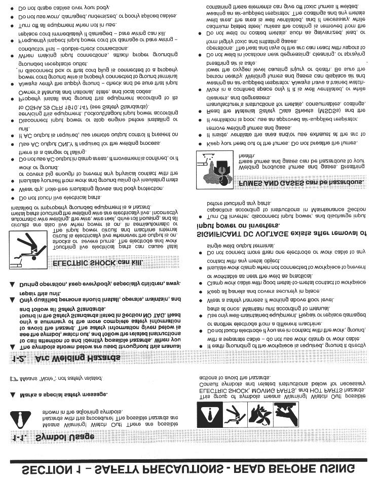
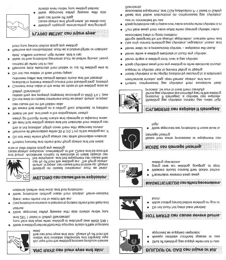
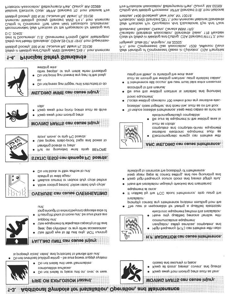
8 1.0 INTRODUCTION Your new stud welding equipment has been carefully constructed using the finest components and material available. Used properly, this equipment will give you many years of profitable, efficient service. The system incorporates the latest in engineering advances for complete, reliable end welding of mild steel, stainless steel and aluminum fasteners. A careful study of this manual will enable you to understand how the welder operates to insure proper performance under all conditions. 2.0 WARRANTY The electrical and mechanical components of the stud welder are thoroughly performance inspected prior to assembly in the welder. The assembled welder is also completely performance tested. All parts used in the assembly of the welder and its accessories are fully warranted for a period ninety (90) days for date of delivery. Under the warranty, the manufacturer reserves the right to repair or replace, at their option, any defective part or parts which fail during the warranty period. Notice of any claim for warranty repair or replacement must be furnished to the manufacturer by the purchaser within ten (10) days after the defect is first discovered. The manufacturer does not assume any liability for paying shipping costs or for any labor or material furnished where such costs are not expressly authorized in writing. The manufacturer does not warrant any parts or accessories against failures resulting from misuse, abuse, improper installation, maladjustment or use not in accordance with the operating instructions furnished by the manufacturer. The warranty is valid only when studs are purchased from sources approved by the manufacturer or are of identical specifications to the manufacturers. 3.0 UNPACKING YOUR UNIT Upon receipt of your unit, place it as close as possible to the point of installation before unpacking it. Once the unit is unpacked, it is recommended that you inspect it for any physical damage that may have occurred in shipping. Your unit has been completely assembled and inspected at the factory. Upon receipt, the unit must be hooked up to the recommended incoming power before welding. Place the unit in a large enough area to provide adequate ventilation. Do not restrict the air flow around the front louvers or from the fan at the rear of the unit. Do not allow water to enter the unit in any way. 4.0 SUGGESTED SAFETY PRECAUTIONS In any welding operation, it is the responsibility of the welder to observe all safety rules to insure his or her personal safety and to protect those working in the area. Reference is directed without endorsement or recommendation to ANSI Z49.1, Safety in Welding and Cutting, and to AWG Publication A6,1-66, Recommended Safe Practices for Gas-Shielded Arc Welding. 4.1 PERSONAL SAFETY PRECAUTIONS 1. Always treat electricity with respect. Under open circuit conditions, the welding machines output voltage may be dangerous. 2. Don t work on live circuits or conductors. Disconnect the main power before checking the machine or performing any maintenance or repair operations. 3. Be sure the welding machine cabinet is properly grounded to a good electrical ground. Consult local electrical codes. 4. Never operate a welder in the rain, or operate a welder while standing in water. Avoid wearing wet or sweaty clothes when welding. 5. Don t operate with worn or poorly connected cables, and don t operate the weld gun with loose cable connections. Inspect all cables frequently for insulation failures, exposed wires, loose connections and repair as needed. 6. Don t overload welding cables or continue to operate with over heated cables. 7. Don t weld near flammable materials or liquids in or near the area, or on ducts or pipes carrying explosive gases. 8. Don t weld on containers which have held combustible or flammable materials, or on materials which give off flammable or toxic vapors when heated. 9. Be sure to provide proper ventilation when welding in a PAGE 1
9 confined area. 10. Never look at the electric arc without wearing protective eye shields. 11. Always use the proper protective clothing, gloves, etc. 12. Never strike an arc when near a bystander who is unaware of the dangers of ultraviolet light to their eyes. 4.2 POWER SUPPLY SAFETY PRECAUTIONS 1. Always connect the frame to the power supply to ground in accordance with the National Electrical Code and the manufacturer s recommendations. 2. Installation, servicing, or trouble shooting should be done by qualified personnel trained to work on this type of equipment. 3. Before servicing this piece of equipment, turn off the disconnect switch at the fuse box. 4. When in operation, all the covers must be on the equipment. 5.0 GENERAL DESCRIPTION THE PROCESS Stud welding is a time saving tool which semi-automatically arc welds the FULL CROSS-SECTION of a weld stud to the base material in a fraction of a second and develops superior strength over normal arc welding procedures. Since the ARC-800 stud welding system provides the proper arc length and allows you to select the proper arc time and welding current, the variables that affect weld quality are minimized. THE UNIT The ARC-800 is a compact and portable stud welding power supply capable of welding studs through 1/2 diameter weld base. The power supply which operates on single phase power has the added feature of weld current regulation that improves stud welding consistency. Both the weld time and weld current are infinitely adjustable for preciseness and repeatability A specially designed electronic gun control circuit has been incorporated in this system. If a fault condition occurs due to a shorted gun solenoid or a faulty control cable, the circuit 6.0 ELECTRICAL INPUT REQUIREMENT This welding power source is designed to be operated from single-phase, 60 Hertz, AC power supply which has a line voltage rating that corresponds with one of the electrical input voltage shown on the nameplate or input data label. Adequate incoming power must be available to obtain maximum performance. The ARC-800 should be operated from a separate fused or circuit breaker protected circuit. Install two primary leads plus one ground wire (see table for proper wire and fuse sizes) through the inlet hole in the rear of the unit, using proper strain relief. The primary cables connect to terminals L or line. A third lead (ground connection) should be fastened to the terminal labeled GND. The other end the ground lead or cable should be attached to a suitable ground such as a water pipe, ground rod, ect. Use whatever grounding means is acceptable to the local electrical inspection authorities. Consult the local electric utility if there is any question about the type of electrical system available at the installation site or how proper connections to the welding power source are to be made. INPUT VOLTS 200/230/460 AMPS 100/100/50 SINGLE PHASE 60 HZ L1 L2 GND V PRO WELD INTERNATIONAL ARC L1 L2 GND V PLACE JUMPERS AS SHOWN FOR THE VOLTAGE BEING USED Figure 1 Jumper Link Arrangement PRIMARY WIRE DELAY TYPE FUSE SIZE-AWG GND SIZE IN AMPS 208V #4 # V #4 # V #10 #10 50 This unit is equipped with input voltage jumper links either installed or in a bag on the jumper link board to allow operation from different line voltages. If installed, the jumper links are positioned for the highest voltage stated on the nameplate or on the input data label. In either case the jumper links should always be checked to see if they are properly positioned for the voltage being used. Open the access door located on the lower portion of the rear panel to expose the jumper link board. If necessary, reposition the jumper links to match the line voltage being used. (see Figure 1) L1 L2 GND 7 5 OUTPUT VOLTS 42 AMPS 1000 MAX O.C.V V PAGE 2

10 Figure 2 CONTROL PANEL FRONT will prevent gun triggering and eliminate damage to printed circuit boards. 7.0 CONTROL PANEL DESCRIPTION ON/OFF SWITCH The ARC-800 is turned ON by turning the knob on the switch to the ON position. WELD TIME ADJUSTMENT The weld timer regulates duration of the weld current. The timer is calibrated in seconds from.05 to.6 seconds. WELD CURRENT ADJUSTMENT The weld current is adjustable Amperes. GUN FAULT LED INDICATOR The gun fault LED on indicates a shorted gun solenoid or a shorted control cable. The LED will stay on and lock out the gun from triggering. TRIGGER LED The trigger LED on indicates a complete circuit to the unit through the gun control cables and gun switch. This LED will turn on whenever gun trigger is pressed. 8.0 WELD GUN SET-UP 8.1 Plunge Length 1. A different and correctly sized chuck and ferrule grip are needed for each different stud diameter and style that will be welded (see PRO WELD Accessories catalog for help in this area). The appropriate chuck, or stud holder, is inserted into the tapered chuck adapter and tapped lightly to insure a tight fit. The ferrule grip is inserted in the hole in the foot and secured with the locking screws to hold it in place. 2. Studs must NOT bind or hang up on the foot, ferrule grip, or ferrule during the entire stud welding process. To assure this, the foot/ferrule arrangement must be centered in relation to the stud to be welded. To assure centering, loosen the leg screws that hold the foot to the legs. Place a stud in the chuck and a ferrule in the ferrule grip. With the leg screws loosened, the foot will move freely in all directions. Adjust the foot so that the stud is centered in the ferrule and no contact occurs between the stud and the ferrule during retraction or forward plunge of the stud. 3. The plunge length is the amount of the stud exposed beyond the ferrule during initial set-up. Set the plunge by loosening the leg adjusting screws and moving the foot until the stud extends 1/8 to 3/16 past the end of the ferrule. Tighten the leg adjusting screws after setting the plunge and recheck centering to be sure the stud is aligned properly in the ferrule. 4. The lift height, which determines the arc length, has been preset at the factory and will automatically lift and plunge the stud during the welding process. Lift, is the distance the gun will raise the stud above the welding surface during the weld. This distance governs the voltage and the arc. Improper lift will cause unsatisfactory welds. Refer to paragraph 8-1 if it becomes necessary to adjust the lift height. 5. Make sure that the cables are connected to the power PAGE 3
11 source (standard set-up is straight polarity - Negative to controller (or gun) and Positive (ground cable) to the work surface). 6. Turn on the power supply and adjust the current and time for the weld base diameter of the fastener to be welded. 7. Place the gun, loaded with the stud and ferrule, squarely against the grounded work surface. The main spring in the gun will take up the plunge length and the ferrule will seat against the base plate. DO NOT MOVE THE GUN DURING THE WELD CY- CLE 8. Pull the trigger holding the gun completely still as above. The gun will lift the stud from the base plate and draw an arc. The end of the stud and the adjacent material of the base plate, will be melted by the weld arc. The gun will then plunge the stud into the molten pool, extinguishing the arc, to end the controlled portion of the weld cycle. 9. After the controlled weld cycle, allow the molten metal to solidify briefly with the work surface to assure completion of the cycle (about an extra second holding "still" after the weld is usually sufficient). 10. Remove the gun from the work by lifting straight away from the welded stud (this will assure better life to the gun's expendable accessories). The ferrule may now be removed by breaking it away from the welded stud to allow inspect- tion of the weld results. After inspection of sample welds the gun can be adjusted, as per the step in this procedure, for optimum results. 8.2 Checking Gun Lift To measure lift, turn the stud welding unit on and set the timer to maximum time. (On certain units there may be a Lift Check switch available, and in these cases this switch can be used to check lift.) Trigger the gun in the air, or on a non-grounded or insulated surface, to observe the lift cycle. Measuring the distance the stud or gun mechanism moves equals lift - usually this can be easily done by visual observation or simple measurement against a static reference point (i.e. the ferrule properly seated in the ferrule grip). Recommended Lift Settings. Stud Base Dia. Lift Setting Less than 1/2 1/16 1/2 through 3/4 3/32 Greater than 3/4 7/64 When it does become necessary to adjust lift, you do so by removing the rear cap from the gun. This will expose the rear coil yoke assembly, the set screw and the lift adjusting screw (Loosen the set screw to avoid damaging the threads of the lift adjusting screw). To increase lift: turn the lift adjusting screw out (counter clockwise). PAGE 4
12 9.0 SETTING UP THE POWER SOURCE 9.1 Connections and settings. CAUTION Welding procedures are covered in Sections 4.28 and Weld test and inspection is covered in Section 4.30, paragraphs 1 through 4. (American Welding Society, inc., 2501 N.W. 7th. Street, Miami, Fla ) Turn the power off before making connections a) Connect the male end of the GROUND CABLE to the positive GROUND terminal of the power supply, and secure the C clamp to the base plate. Make sure both connections are tight and the base metal is free of heavy paint or rust at the ground connection points. b) Connect the male end of the COMBINATION CABLE SET to the negative GUN terminal of the power supply. c) Plug in the control cable portion of the COMBINATION CABLE SET into the control cable receptacle in the front of the power supply. d) Set the Time adjustment required for the particular stud size. (see table 9-1) e) Set the Current adjustment to the current setting for the particular stud size. (see table 9-1) f) Turn on the power supply by depressing the START button. Table 9-1 Approximate Settings Stud Base Weld Weld Minimum Plate GOOD STUD WELD A good full fillet COLD WELD Increase weld current and/or weld time STUD HANG UP Adjust foot to insure the stud is centered in the ferrule HOT WELD Reduce weld current and/or weld time Inches mm Seconds Amperes Inches mm 1/ / / / / Weld Test and Inspection Testing of weld quality beyond visual inspection varies with stud characteristics. Refer to AWS (American Welding Society) Structure Welding code AWS D.1Rev A. Bend Test figure 4 WELD INSPECTION Repeatedly bend the stud away from its axis until failure occurs. B. Torque Test - Threaded Studs Twist the stud to point of failure. Apply a twisting tensile load by using a collar, washer and nut. C. Test Results In an acceptable weld, failure will occur in the stud material or tear out of a thin base plate. Failure in the weld requires adjustment of procedure, weld time, weld current, or gun PAGE 5
13 setup MAINTENANCE CAUTION Electric Shock Can Kill: 10.2 Internal Cleaning Every six months blow or vacuum dust and dirt from the inside of the welding power source. Remove the outer enclosure, and use a clean, dry airstream or vacuum suction for the cleaning operation. If dusty or dirty conditions are present, clean the unit monthly. Do not touch live electrical parts. Shut down welding power source, and disconnect input power before inspecting, maintaining, or servicing. Lockout/tagging procedures consist of padlocking line disconnect switch in the open position, removing fuses from fuse box, or shutting off and red-tagging circuit breaker or other disconnecting device. MOVING PARTS can cause serious injury. Keep away from moving parts. HOT SURFACES can cause severe burns. Allow cooling period before servicing. CAUTION Read and follow the safety information at the beginning of this section before proceeding Weld Cables Every three months inspect cables for breaks in insulation. Repair or replace cables if insulation breaks are present. Clean and tighten connections at each inspection. Figure 5 FUSE BLOCK PAGE 6
14 11.0 TROUBLE SHOOTING CAUTION Read and follow the safety information at the beginning of this section before proceeding Whenever possible, have a qualified electrician do the maintenance and trouble shooting work. Turn the input power off using the disconnect switch at the fuse box before working inside the machine. Trouble Possible Cause What To Do Unit trips off without 1. Defective main SCR. 1. Check for defective SCR and welding. replace. 2. Defective sustaining arc SCR. 2. check and replace. 3. Unit Overheated. 3. Allow unit to cool/ then reduce weld rate to prevent reoccurrence. 4. Defective thermal switch. 4. Check and replace. 5. Defective P.C. board. 5. Replace. 6. Shorted control cables. 6. Repair. Low output. 1. Low incoming line voltage 1. Current low line voltage. 2. Incorrect jumper link connection 2. Check jumper links on primary on primary board. board for proper voltage. 3. Defective P.C. board. 3. Replace. 4. Defective current potentiometer. 4. Replace. 5. Excessive weld cable length. 5. Reduce cable length. Maximum output but 1. Defective P.C. board. 1. Replace. no control. 2. Open lead going to shunt 2. Repair broken leads on (shielded cable). connection. 3. Defective current potentiometer. 3. Replace. Gun does not lift. 1. Blown 4 amp fuse. 1. Check and replace fuse. 2. Defective P.C. board. 2. Replace. 3. Defective control cable or 3. Repair short in cable, replace gun coil. gun coil. 4. Defective trigger switch on gun. 4. Replace. 5. Blown 1 Amp fuse. 5. Replace. Gun lifts but does not 1. Blown 15 amp sustaining arc fuse. 1. Check and replace fuse. weld. 2. Defective sustaining arc SCR(s). 2. Replace bad part(s). 3. Defective P.C. board. 3. Replace. 4. Defective choke coil. 4. Check and Replace. 5. Open weld cable or bad weld 5. Check and Repair. ground connection. Gun lifts but does not 1. Defective P.C. board. 1. Replace. Plunge. 2. Defective time potentiometer. 2. Replace. 3. Bind within welding gun. 3. Perform gun maintenance PAGE 7


15 Figure 6 FRONT PANEL 9 10 Figure 7 CONNECTORS 12.0 PARTS LIST ITEM DESCRIPTION PART NUMBER 1 Front Decal Knob LED Red LED Green Knob Face Plate On/Off Switch Potentiometer Camlok, Female Panel Mount Panel Mount R&S Connector PAGE 8

16 Figure 8 INTERNAL VIEW ITEM DESCRIPTION PART NUMBER 12 SCR Clamp Heat Sink Thermostat SCR, Isolated 25A 400V Cap, 1000 MFD 200V Terminal Strip 12 Pole Euro Choke Coil Terminal Fuse Block Fuse Decal Terminal Strip 12 Pole Euro SCR ARC-800 PCB PAGE 9


17 Figure 9 INTERNAL VIEW ITEM DESCRIPTION PART NUMBER 24 M/TRANS/ /230/460/60hz Wheels Axle Cap Shunt Sheet Metal / Misc. Parts (NOT PICTURED) DESCRIPTION PART NUMBER Base Left Side Panel Right Side Panel Top Cover Front Panel Back Panel MTG Panel Compartment Rear Door Handle Axle Handle, Plastic Door Latch Knob Door Latch Cam PAGE 10
18 Figure 9 CONTROL P.C. BOARD P/N K 2.2K 2.2K 2.2K 2.2K 2.2K 2.2K 2.2K 2.2K 2.2K 2.2K 2.2K K 1K 1K 1K 1K K 4.7K 4.7K 4.7K 22K 22K K 22K 22K 3.3K 3.3K 3.3K 47K 1.8K 82K 130K 2.7K 3.9K 3K 390K 47 33K 1M 470M 40V 100M 25V 10M 250V 47M 63V.47/63.22/ A06 A56 A06 A06 A06 A56 A06 A56 A56 TCR LM723 LM358 LM358 LM358 LM358 LM358 MOC 3020 H11C6 H11C6 H11G3 MCT6 HP4503 MOC 3020 LM317 24N60 100K 100K BU806 BTA06.25 PAGE 11
19
20 MANUFACTURED BY PRO WELD MADE IN THE U.S.A.
OPERATION/ MAINTENANCE MANUAL
 208 VERSION OPERATION/ MAINTENANCE MANUAL TABLE OF CONTENTS Section 1 SAFETY PRECAUTIONS PAGE 1.0 INTRODUCTION... 1 2.0 WARRANTY... 1 3.0 UNPACKING YOUR UNIT... 1 4.0 SUGGESTED SAFETY PRECAUTIONS... 1
ARC 1850 LIST OF FIGURES
 PAGE 1.0 INTRODUCTION... 1 2.0 WARRANTY... 1 3.0 UNPACKING YOUR UNIT... 1 4.0 SUGGESTED SAFETY PRECAUTIONS...... 1 4.1 PERSONAL SAFETY PRECAUTIONS. 1 4.2 POWER SUPPLY SAFETY PRECAUTIONS.. 2 5.0 GENERAL
OPERATION/ MAINTENANCE MANUAL
 OPERATION/ MAINTENANCE MANUAL TABLE OF CONTENTS Section 1 SAFETY PRECAUTIONS PAGE 1.0 INTRODUCTION... 1 2.0 WARRANTY... 1 3.0 UNPACKING YOUR UNIT... 1 4.0 SUGGESTED SAFETY PRECAUTIONS... 1 4.1 PERSONAL
OPERATION/ MAINTENANCE MANUAL
 OPERATION/ MAINTENANCE MANUAL TABLE OF CONTENTS PAGE 1.0 INTRODUCTION... 1 2.0 WARRANTY... 1 3.0 UNPACKING YOUR UNIT... 1 4.0 SUGGESTED SAFETY PRECAUTIONS...... 1 4.1 PERSONAL SAFETY PRECAUTIONS. 1 4.2
Cutlass Fasteners, Inc. 83 Vermont Ave., Unit 6, Warwick, RI Tel: (401) Fax: (401) cutlass-studwelding.com
 Fax: (401) cutlass-studwelding.com") MODEL : BANTAM C8 BANTAM C10 PART NO. : 602-325A 602-343A SERIAL NO. : PLEASE READ THIS OPERATION AND MAINTENANCE MANUAL CAREFULLY BEFORE USING YOUR NEW CUTLASS STUD WELDER. COPYRIGHT CFI 2009 email: sales@
MODEL : BANTAM C8 BANTAM C10 PART NO. : 602-325A 602-343A SERIAL NO. : PLEASE READ THIS OPERATION AND MAINTENANCE MANUAL CAREFULLY BEFORE USING YOUR NEW CUTLASS STUD WELDER. COPYRIGHT CFI 2009 email: sales@
Cutlass Fasteners, Inc. 83 Vermont Ave., Unit 6, Warwick, RI Tel: (401) Fax: (401) cutlass-studwelding.com
 Fax: (401) cutlass-studwelding.com") MODEL : PHM-10 SHORT CYCLE WELD GUN PART NO. : PHM-10 SERIAL NO. : PLEASE READ THIS OPERATION AND MAINTENANCE MANUAL CAREFULLY BEFORE USING YOUR NEW CUTLASS STUD WELDER. COPYRIGHT CFI 2009 email: sales@
MODEL : PHM-10 SHORT CYCLE WELD GUN PART NO. : PHM-10 SERIAL NO. : PLEASE READ THIS OPERATION AND MAINTENANCE MANUAL CAREFULLY BEFORE USING YOUR NEW CUTLASS STUD WELDER. COPYRIGHT CFI 2009 email: sales@
Cutlass Fasteners, Inc. 83 Vermont Ave., Unit 6, Warwick, RI Tel: (401) Fax: (401) cutlass-studwelding.com
 Fax: (401) cutlass-studwelding.com") MODEL : BANTAM C8 PART NO. : 602-325P SERIAL NO. : PLEASE READ THIS OPERATION AND MAINTENANCE MANUAL CAREFULLY BEFORE USING YOUR NEW CUTLASS STUD WELDER. COPYRIGHT CFI 2009 email: sales@ PAGE - 1 - WARRANTY
MODEL : BANTAM C8 PART NO. : 602-325P SERIAL NO. : PLEASE READ THIS OPERATION AND MAINTENANCE MANUAL CAREFULLY BEFORE USING YOUR NEW CUTLASS STUD WELDER. COPYRIGHT CFI 2009 email: sales@ PAGE - 1 - WARRANTY
OPERATION/ MAINTENANCE MANUAL
 OPERATION/ MAINTENANCE MANUAL TABLE OF CONTENTS 1.0 INTRODUCTION 1 2.0 WARRANTY 1 3.0 UNPACKING YOUR UNIT 1 4.0 SUGGESTED SAFETY PRECAUTIONS 1 5.0 GENERAL DESCRIPTION 2 6.0 THE CD ING PROCESS 2 7.0 POWER
OPERATION/ MAINTENANCE MANUAL
 OPERATION/ MAINTENANCE MANUAL TABLE OF CONTENTS 1.0 INTRODUCTION 1 2.0 WARRANTY 1 3.0 UNPACKING YOUR UNIT 1 4.0 SUGGESTED SAFETY PRECAUTIONS 1 5.0 GENERAL DESCRIPTION 2 6.0 THE CD ING PROCESS 2 7.0 POWER
OPERATION MANUAL MODELS TWE-250 TWE-321 TWE-375 TRU WELD EQUIPMENT COMPANY 6400 N. HONEYTOWN ROAD SMITHVILLE, OHIO (330)
") OPERATION MANUAL MODELS TWE-250 TWE-321 TWE-375 TRU WELD EQUIPMENT COMPANY 6400 N. HONEYTOWN ROAD SMITHVILLE, OHIO 44677 (330) 669 2773 CONTENTS Section Description Pages 1 Introduction 3 2 External Features
OPERATION MANUAL MODELS TWE-250 TWE-321 TWE-375 TRU WELD EQUIPMENT COMPANY 6400 N. HONEYTOWN ROAD SMITHVILLE, OHIO 44677 (330) 669 2773 CONTENTS Section Description Pages 1 Introduction 3 2 External Features
OPERATOR S MANUAL StudPro LiteXI Pin Welder Stud Welding Products, Inc
 OPERATOR S MANUAL StudPro LiteXI Pin Welder CONTENTS Description Pages Safety 2 Specifications and Features 3 Product Components 4-5 Screen Operation 6-8 Setup and Welding 9-11 CD Gun Exploded View 12
OPERATOR S MANUAL ACE - P100
 OPERATOR S MANUAL ACE - P100 Pin Welder TRU-WELD EQUIPMENT COMPANY www.truweldstudwelding.com (330) 725-7744 CONTENTS Description Pages Warranty Information 1 Safety 2 Specifications and Features 3 Product
OPERATION MANUAL MODELS TWE-250 TWE-321 TWE-375 TRU WELD EQUIPMENT COMPANY 6400 N. HONEYTOWN ROAD SMITHVILLE, OHIO (330)
") OPERATION MANUAL MODELS TWE-250 TWE-321 TWE-375 TRU WELD EQUIPMENT COMPANY 6400 N. HONEYTOWN ROAD SMITHVILLE, OHIO 44677 (330) 669 2773 Version 1.3 Date 10/20/2010 TRU WELD EQUIPMENT LIMITED WARRANTY All
OPERATION MANUAL MODELS TWE-250 TWE-321 TWE-375 TRU WELD EQUIPMENT COMPANY 6400 N. HONEYTOWN ROAD SMITHVILLE, OHIO 44677 (330) 669 2773 Version 1.3 Date 10/20/2010 TRU WELD EQUIPMENT LIMITED WARRANTY All
OPERATION MANUAL. TWE Pin Welder. Model TWP-2 TRU WELD EQUIPMENT COMPANY 6400 N. HONEYTOWN ROAD SMITHVILLE, OHIO (330) Revision 2.
 Revision 2.") OPERATION MANUAL TWE Pin Welder Model TWP-2 TRU WELD EQUIPMENT COMPANY 6400 N. HONEYTOWN ROAD SMITHVILLE, OHIO 44677 (330) 725 7744 Revision 2.0 8/22/2013 TRU WELD EQUIPMENT LIMITED WARRANTY All goods
OPERATION MANUAL TWE Pin Welder Model TWP-2 TRU WELD EQUIPMENT COMPANY 6400 N. HONEYTOWN ROAD SMITHVILLE, OHIO 44677 (330) 725 7744 Revision 2.0 8/22/2013 TRU WELD EQUIPMENT LIMITED WARRANTY All goods
OPERATOR S MANUAL. TW-i SERIES. Capacitor Discharge Stud Welder. MODELS: TW-i 250 TW-i 250CP TW-i 321 TW-i 375
 OPERATOR S MANUAL TW-i SERIES Capacitor Discharge Stud Welder MODELS: TW-i 250 TW-i 250CP TW-i 321 TW-i 375 TRU-WELD EQUIPMENT COMPANY www.truweldstudwelding.com (330) 725-7744 CONTENTS Description Pages
QPET, QPETXU Battery Chargers
 C O R P O R A T IO N O P E R A T I N G I N S T R U C T I O N S QPET, QPETXU Battery Chargers INTRODUCTION: The QPET line of chargers are designed for general purpose deep cycle batteries. They are an electronically
OPERATION MANUAL. Model TWP-2. Toll free customer support:
 OPERATION MANUAL TWE StudPro Pin Welder Lite Model TWP-2 Downey, CA 9459 Washburn Rd. Downey, CA 90242 Phone- 800.252.1919 Fax- 562.862.3022 Hayward, CA Phoenix, AZ 2391 American TRU WELD Ave. EQUIPMENT
POWER PINNER CD HAND WELDER 7300 OPERATOR S MANUAL
 POWER PINNER CD HAND WELDER 7300 OPERATOR S MANUAL Copyright: April 7, 2014 Gripnail Corporation Revised: January 25, 2018 An Employee Owned Company 97 Dexter Road East Providence, Rhode Island 02914-2045
OPERATOR S MANUAL STUDPRO SERIES
 OPERATOR S MANUAL STUDPRO SERIES Capacitor Discharge Stud Welder MODELS: StudPro 2500XI StudPro 2500XIP StudPro 3125XI StudPro 3750XI CONTENTS Description Pages Safety 2 Specifications and Features 3 Product
OPERATION INSTRUCTIONS
 www.r-techwelding.co.uk Email: sales@r-techwelding.co.uk Tel: 01452 733933 Fax: 01452 733939 ProArc 175 INVERTER ARC WELDER OPERATION INSTRUCTIONS Version 2017-10 2 3 Thank you for selecting the R-Tech
POWER PINNER HAND WELDER 7200 OPERATOR S MANUAL
 POWER PINNER HAND WELDER 7200 OPERATOR S MANUAL Copyright: January 5, 2009 Revised: November 24, 2014 Serial No. 0901189 - Gripnail Corporation An Employee Owned Company 97 Dexter Road East Providence,
OBE, OBEXU, ON BOARD Battery Chargers
 C O R P O R A T IO N O P E R A T I N G I N S T R U C T I O N S OBE, OBEXU, ON BOARD Battery Chargers INTRODUCTION: These chargers are designed for the permanent installation on battery powered vehicles
QSSE, QSSEX INDUSTRIAL Battery Chargers
 C O R P O R A T IO N O P E R A T I N G I N S T R U C T I O N S QSSE, QSSEX INDUSTRIAL Battery Chargers INTRODUCTION The QSE line are electronically controlled float chargers. The batteries are brought
Cutlass Fasteners, Inc. 83 Vermont Ave., Unit 6, Warwick, RI Tel: (401) Fax: (401) cutlass-studwelding.com
 Fax: (401) cutlass-studwelding.com") MODEL : PINTO YTEM/PKM-1B GUN PART NO. : C-1K ERIAL NO. : PLEAE READ THI OPERATION AND MAINTENANCE MANUAL CAREFULLY BEFORE UING YOUR NEW CUTLA TUD WELDER. COPYRIGHT CFI 2009 email: sales@ PAGE - 1 - WARRANTY
MODEL : PINTO YTEM/PKM-1B GUN PART NO. : C-1K ERIAL NO. : PLEAE READ THI OPERATION AND MAINTENANCE MANUAL CAREFULLY BEFORE UING YOUR NEW CUTLA TUD WELDER. COPYRIGHT CFI 2009 email: sales@ PAGE - 1 - WARRANTY
OPERATION MANUAL TWE-375 CAPACITOR DISCHARGE WELDER
 OPERATION MANUAL TWE-375 CAPACITOR DISCHARGE WELDER TRU WELD EQUIPMENT COMPANY 6400 N. HONEYTOWN ROAD SMITHVILLE, OHIO 44677 (330) 725 7744 TWE@tfpcorp.com Version 1.0 Date 8/13/2013 TRU WELD EQUIPMENT
OBAE, OBAEXU, ON BOARD Battery Chargers
 C O R P O R A T IO N O P E R A T I N G I N S T R U C T I O N S OBAE, OBAEXU, ON BOARD Battery Chargers INTRODUCTION: The OBAE line of chargers are designed for the permanent installation on battery powered
MMA 160S ARC/MMA WELDER OPERATION INSTRUCTIONS
 www.r-techwelding.co.uk MMA 160S ARC/MMA WELDER OPERATION INSTRUCTIONS 2 Thank you for selecting the R-Tech MMA160S Inverter Arc Welder. The MMA160S has many benefits over traditional Arc welders, including
OPERATION MANUAL M185. MIG/flux wire feeder welder. Serial Number: Where Purchase: Date of purchased:
 OPERATION MANUAL M185 MIG/flux wire feeder welder Serial Number: Where Purchase: Date of purchased: CONTENT 1. Safety... 2 2. Electrical principle drawing... 4 3. Specifications... 5 4. Front and rear
Operator s Manual Model AC300 ARC Welder
 Operator s Manual Model AC300 ARC Welder WARNING: Do not assemble, install, or operate this equipment without reading ALL of this manual and the safety precautions and warnings illustrated in this manual.
CDMF110 PINSPOTTER OWNER S MANUAL MACHINERY DIVISION
 CDMF110 c d m f 1 1 CDMF110 PINSPOTTER OWNER S MANUAL MACHINERY DIVISION UNIT INSTRUCTIONS Please follow all CDMF110 Safety Instructions. Contact your Duro Dyne Tech Service if you have any operating questions.
MODEL 7100 PORTABLE PIN WELDER OPERATOR S MANUAL
 Model 7100 Portable Pin Welder MODEL 7100 PORTABLE PIN WELDER OPERATOR S MANUAL Copyright: March 22, 2005 Revised: December 20, 2016 Gripnail Corporation An Employee Owned Company 97 Dexter Road East Providence,
CALTRAP INSTALLATION AND OPERATIONS MANUAL
 INSTALLATION AND OPERATIONS MANUAL NOTE Please read this entire installation and operations manual before energizing the. Safety Considerations: Installing and servicing capacitor equipment can be hazardous.
24 VOLT AUTOMATIC BATTERY CHARGER PART NO
 24 VOLT AUTOMATIC BATTERY CHARGER PART NO. 957732 AC Input: DC Output: Battery Type: Specifications 230 volts, 50 hertz, 3.5 amps, single-phase 24 volts, 20 amps initially tapering to 6 amps 24 volt, 12
PRODUCT MANUAL TILE CUTTING MACHINE. . Operation. Parts List and Diagram SPECIFICATIONS CAUTION:
 FLORCRAFTT TM PRODUCT MANUAL SKU NUMBER 709-4242 SERIAL NUMBER: CAUTION: FOR YOUR OWN SAFETY READ INSTRUCTION MANUAL COMPLETELY AND CAREFULLY BEFORE OPERATING THIS 7 TILECUTTING MACHINE SPECIFICATIONS
LESTRONIC II BATTERY CHARGER MODEL 07210
 LESTRONIC II BATTERY CHARGER MODEL 07210 PLEASE SAVE THESE IMPORTANT SAFETY AND OPERATING INSTRUCTIONS For correct operation of the equipment, it is important to read and be familiar with this entire manual
LESTRONIC II BATTERY CHARGER MODEL 19740
 *01679* LESTRONIC II BATTERY CHARGER MODEL 19740 PLEASE SAVE THESE IMPORTANT SAFETY AND OPERATING INSTRUCTIONS For correct operation of the equipment, it is important to read and be familiar with this
AUTOMATIC BURNISHER MODEL FURY 21 HSB
 AUTOMATIC BURNISHER MODEL FURY 21 HSB INTRODUCTION OPERATING & MAINTENANCE INSTRUCTIONS This operator s book has important information for the use and safe operation of this machine. Read this book carefully
NSGV PT-1000 PORTABLE WELDING STATION I, O & M MANUAL
 APPLICATION OF DUST CONTROL EQUIPMENT: CAUTION - Warning Improper operation of dust control system may contribute to conditions in the work area or facility that could result in severe personal injury
LESTRONIC II BATTERY CHARGER BUILT-IN OR PORTABLE CHARGERS
 LESTRONIC II BATTERY CHARGER BUILT-IN OR PORTABLE CHARGERS PLEASE SAVE THESE IMPORTANT SAFETY AND OPERATING INSTRUCTIONS For correct operation of the equipment, it is important to read and be familiar
Automatic taper of charge rate for superior battery life through good equalization of cells and low water use rate.
 FEATURES Automatic taper of charge rate for superior battery life through good equalization of cells and low water use rate. Silicon diodes with inherent surge protection operated at a conservative percentage
TURNING ROLLS 00338OG WARNINGS, SAFEGUARDS & OPERATING INSTRUCTIONS
 TURNING ROLLS 00338OG091207 WARNINGS, SAFEGUARDS & OPERATING INSTRUCTIONS Warnings and Safeguards for Welding and Cutting Operations IMPORTANT - Protect yourself and others! Remember that safety depends
TWE Operations Manual
 HEAVY-DUTY STUD GUN Operations Manual The TWE17000 has been designed to fit comfortably for all hands, including when wearing a work glove. The neck of the handle has been tapered so that when grasped,
Stick/Mig Capability Welding Excellence Modular Construction Environment Protected 2,000 Watt AC Power for Tools
 E300 3+2 Electric Welder Service Manual Stick/Mig Capability Welding Excellence Modular Construction Environment Protected 2,000 Watt AC Power for Tools SVM_E300 3+2 SAFETY Arc Welding Safety Precautions
PBA Series Prelube Controls
 VARNA Products Engineered Innovation PBA Series Prelube Controls Simple, Compact, Industrial Full featured control for running prelube from the control or from a remote station Easy internal wiring connections
MODEL ELC-12/60-D BATTERY CHARGER
 *32198* NATIONAL RAILWAY SUPPLY Installing, Operating and Service Instructions for the 12/60 Solid State Charger MODEL ELC-12/60-D BATTERY CHARGER PLEASE SAVE THESE IMPORTANT SAFETY AND OPERATING INSTRUCTIONS
24/3000H-3PH 24/4500H-3PH 24/6000H-3PH
 Manufacturer of Dimensions TM Inverters 4467 White Bear Parkway St. Paul, MN 55110 Phone: 651-653-7000 Fax: 651-653-7600 E-mail: inverterinfo@sensata.com Web: www.dimensions.sensata.com 120015D OWNERS
I. INSTALLATION INSTRUCTIONS
 I. INSTALLATION INSTRUCTIONS IT SHALL BE THE RESPONSIBILITY OF THE INSTALLER OF SELF--CONTAINED COMPACTORS TO INSTALL SELF--CONTAINED COMPACTORS IN ACCORDANCE WITH APPLICABLE CODES, LOCAL ORDINANCES, AND
CLEAN POWER TM CPS Series Operator s Manual
 12 Test Equipment CLEAN POWER TM CPS Series Operator s Manual Power Supply / Maintenance Charger for 12 Volt Systems The CPS series of power supplies / maintenance chargers are the ultimate in supplying
ACC Series Power Conditioner OPERATION & INSTALLATION MANUAL
 ACC Series Power Conditioner OPERATION & INSTALLATION MANUAL PHASETEC digital power conditioners are designed to safely operate electrical equipment in the harshest power quality environments. With a wide
ACCUSENSE CHARGE SERIES ON/OFF BOARD FULLY AUTOMATIC BATTERY CHARGER
 ACCUSENSE CHARGE SERIES ON/OFF BOARD FULLY AUTOMATIC BATTERY CHARGER SPECIFICATIONS: *Photo for reference only* Part number 8890439 Mode Select: Selects Battery Type Refer to Section 6. IMPORTANT: READ
Compressor Duty Motor - 1 HP. Model 40132
 Compressor Duty Motor - 1 HP Model 40132 Assembly and Operating Instructions 3491 Mission Oaks Blvd., Camarillo, CA 93011 Visit our web site at http://www.harborfreight.com Copyright 2002 by Harbor Freight
AIR COMPRESSOR OPERATING INSTRUCTION AND PARTS LIST
 AIR COMPRESSOR OPERATING INSTRUCTION AND PARTS LIST BELT TYPE IMPORTANT PLEASE MAKE CERTAIN THAT THE PERSON WHO IS TO USE THIS EQUIPMENT CAREFULLY READS AND UNDERSTANDS THESE INSTRUCTIONS BEFORE STARTING
User s Manual. Automatic Switch-Mode Battery Charger
 User s Manual Automatic Switch-Mode Battery Charger IMPORTANT Read, understand, and follow these safety rules and operating instructions before using this battery charger. Only authorized and trained service
LESTRONIC II BATTERY CHARGER TAYLOR-DUNN MODEL TYPE 24LC25-8ET
 LESTRONIC II BATTERY CHARGER TAYLOR-DUNN 79-301-10 MODEL 13110-32 TYPE 24LC25-8ET AC Supply: DC Output: Battery Capacity: Specifications 120 volts, 60 Hertz, single-phase 24 volts, 32 amps Use only on
MODEL A97 SERIES. Switchmode Utility Rectifier/Battery Charger ECN/DATE
 MODEL A97 SERIES Switchmode Utility Rectifier/Battery Charger CPN108172 ISSUE DATE: 16071 7/03 ECN/DATE 106 BRADROCK DRIVE DES PLAINES, IL. 60018-1967 (847) 299-1188 FAX: (847)299-3061 Page 1 of 7 INSTRUCTION
A48 / A48B (base plate) BATTERY CHARGER
 BATTERY CHARGER") A48 / A48B (base plate) BATTERY CHARGER CPN41054 ISSUE DATE: 12315-8/98 ECN/DATE 106 BRADROCK DRIVE DES PLAINES, IL. 60018-1967 (847) 299-1188 FAX: (847)299-3061 15349-07-07/02 16041 6/03 14575-2/01 INSTRUCTION
A48 / A48B (base plate) BATTERY CHARGER CPN41054 ISSUE DATE: 12315-8/98 ECN/DATE 106 BRADROCK DRIVE DES PLAINES, IL. 60018-1967 (847) 299-1188 FAX: (847)299-3061 15349-07-07/02 16041 6/03 14575-2/01 INSTRUCTION
MODEL NUMBER: MEDIUM DUTY ONBOARD AIR SYSTEM
 MODEL NUMBER: 10003 MEDIUM DUTY ONBOARD AIR SYSTEM IMPORTANT: It is essential that you and any other operator of this product read and understand the contents of this manual before installing and using
HEAVY DUTY ONBOARD AIR SYSTEM PART NO
 IMPORTANT: It is essential that you and any other operator of this product read and understand the contents of this manual before installing and using this product. SAVE THIS MANUAL FOR FUTURE REFERENCE
D-Series Blowers and Exhausters
 Operation and Maintenance Manual D-Series MONOXIVENT - SOURCE CAPTURE SYSTEMS - info@ Oct. - 2015 MONOXVENT BLOWERS AND EXHAUSTERS D05-1 D05-3 D10-1 D10-3 D15-1 D15-3 D20-1 D20-3 D30-1 D30-3 ½ HP TEFC
INSTRUCTION MANUAL. CAT Place Table Top Centrifuge
 1 INSTRUCTION MANUAL CAT. 72359-06 6-Place Table Top Centrifuge 2 CONTENTS IMPORTANT SAFETY GUIDELINES PLEASE READ BEFORE USE.. 3 SUPPLIED EQUIPMENT... 5 OPTIONAL ACCESSORIES... 5 SETUP... 5 UNPACKING...
3 FT CORD Models , , , FT CORD W/GFCI Models , , ,
 POWERLINE XP II Swimming Pool Pump (Light Oak color model) With Automatic Timer 3 FT CORD Models 0-1395-226, 0-1396-226, 0-1397-226, 0-1398-226 25 FT CORD W/GFCI Models 0-1395-220, 0-1396-220, 0-1397-220,
User s Manual D-Series Blowers and Exhausters
 User s Manual D-Series Blowers and Exhausters D05-1 ½ HP TEFC 115/230 VOLTS, 1 PH D05-3 ½ HP TEFC 208/230/460 VOLTS, 3 PH D10-1 1 HP TEFC 115/230 VOLTS, 1 PH D10-3 1 HP TEFC 208/230/460 VOLTS, 3 PH D15-1
DC to AC Power Inverters
 Manufacturer of Dimensions TM Inverters 4467 White Bear Parkway St. Paul, MN 55110 Phone: 651-653-7000 Fax: 651-653-7600 E-mail: inverterinfo@sensata.com Web: www.dimensions.sensata.com ISO 9001:2000 Certified
MICRO WELD MODEL AUF-8 HEAVY DUTY FERROUS BUTT WELDERS MICRO PRODUCTS COMPANY SERVICE MANUAL
 MICRO WELD MODEL AUF-8 HEAVY DUTY FERROUS BUTT WELDERS MICRO PRODUCTS COMPANY SERVICE MANUAL 1 TABLE OF CONTENTS 1.0 SPECIFICATIONS 2.0 GENERAL OPERATING INSTRUCTIONS 3.0 BASIC OPERATING PARTS 4.0 BASIC
DC to AC Power Inverters
 Manufacturer of Dimensions TM Inverters 4467 White Bear Parkway St. Paul, MN 55110 Phone: 651-653-7000 Fax: 651-653-7600 E-mail: inverterinfo@sensata.com Web: www.dimensions.sensata.com 121114C OWNERS
A1P OPERATING MANUAL
 A1P OPERATING MANUAL TABLE OF CONTENTS Introduction... p. 2 Features... p. 2 Description... p. 3 Theory of Operation... p. 3 Installation... p. 4 Electrical Connections... p. 5 Options... p. 6 Warranty...
Operations and Service Manual. X30208 Load Bank
 Operations and Service Manual Read all instructions before using the load bank Contents 1. Components... 3 Total Assembly... 3 2) Specifications... 4 a)... 4 3) Receiving... 5 4) Safety... 5 a) Ground
dv Sentry TM 208V 600V INSTALLATION GUIDE Quick Reference ❶ How to Install Pages 6 14 ❷ Startup/Troubleshooting Pages WARNING
 dv Sentry TM 208V 600V INSTALLATION GUIDE FORM: DVS-IG-E REL. January 2018 REV. 003 2018 MTE Corporation High Voltage! Only a qualified electrician can carry out the electrical installation of this filter.
MODEL ELC-12/40-CVM-D BATTERY CHARGER
 NATIONAL RAILWAY SUPPLY MODEL ELC-12/40-CVM-D BATTERY CHARGER Installing, Operating and Service Instructions for the ELC-12/40-CVM-D Solid State Charger PLEASE SAVE THESE IMPORTANT SAFETY AND OPERATING
MICRO WELD MODEL DP1 & DP2 HEAVY DUTY NON-FERROUS BUTT WELDERS MICRO PRODUCTS COMPANY SERVICE MANUAL
 MICRO WELD MODEL DP1 & DP2 HEAVY DUTY NON-FERROUS BUTT WELDERS MICRO PRODUCTS COMPANY SERVICE MANUAL 1 TABLE OF CONTENTS 1.0 SPECIFICATIONS 2.0 GENERAL OPERATING INSTRUCTIONS 3.0 BASIC OPERATING PARTS
Hot-Shot Operating Instructions
 Hot-Shot Operating Instructions Model 400, 320, and 300 (For use with Copper and Iron Pipe) Your Hot-Shot is designed to give you years of trouble-free, profitable service. However, no machine is better
MODEL 6010A 6 12 VOLT BATTERY CHARGER ASSOCIATE
 MODEL 600A 6 VOLT BATTERY CHARGER ASSOCIATE IMPORTANT SAFETY INSTRUCTIONS. SAVE THESE INSTRUCTIONS. This manual contains important safety and operating instructions for the battery charger you have purchased.
INVERTER AIR PLASMA CUTTING MACHINE
 INVERTER AIR PLASMA CUTTING MACHINE OPERATION MANUAL DO NOT INSTALL, OPERATE OR MAINTAIN THIS MACHINE WITHOUT READING THIS MANUAL AND PLEASE ALWAYS THINK BEFORE YOU ACT. www.hyundaiwelding.com TECHNICAL
ADI-125/750 ADI-125/1500 ADI-125/2500
 Manufacturer of Dimensions TM Inverters 4467 White Bear Parkway St. Paul, MN 55110 Phone: 651-653-7000 Fax: 651-653-7600 E-mail: inverterinfo@sensata.com Web: www.dimensions.sensata.com 121094B OWNERS
Installation Instructions Electric Heaters 5 20 kw
 Small Packaged Products 2 to 5 Tons Accessory Electric Heaters Cancels: IIK 564A-24-2 IIK 564A-24- -02 Installation Instructions Electric Heaters 5 20 kw NOTE: Read the entire instruction manual before
MMWP125I OWNER S MANUAL
 MMWP125I OWNER S MANUAL 1/2017 WARNING: Read carefully and understand all ASSEMBLY AND OPERATION INSTRUCTIONS before operating. Failure to follow the safety rules and other basic safety precautions may
Installation Instructions
 NOTE: Read the entire instruction manual before starting the installation. This symbol indicates a change since the last issue. SAFETY CONSIDERATIONS Installing and servicing air conditioning equipment
WELDING FUME EXHAUSTERS & ARMS
 WELDING FUME EXHAUSTERS & ARMS The Ace 75 Series is our flexible and effective line of welding fume exhausters and extraction arms for shops that elect to exhaust their weld fumes outdoors instead of through
User s Manual and Operating Instructions
 User s Manual and Operating Instructions Model Numbers: CL-36-BDF-A, CL-42-BDF-A, CL-48-BDF-A E355088 READ AND SAVE THESE INSTRUCTIONS IMPORTANT: Read and understand all of the instructions in this manual
Maintenance Manual 13 AMPERE POWER SUPPLY 19A704647P1-P3. Mobile Communications LBI-31801C
 C Mobile Communications 13 AMPERE POWER SUPPLY 19A704647P1-P3 CAUTION THESE SERVICING INSTRUCTIONS ARE FOR USE BY QUALI- FIED PERSONNEL ONLY. TO AVOID ELECTRIC SHOCK DO NOT PERFORM ANY SERVICING OTHER
INSTALLATION AND MAINTENANCE MANUAL FORM #PM-126 REV A 12/09
 HAND CRANK & MOTORIZED POWER CORD REELS: SERIES 1125PC SERIES: 1125PC HAND CRANK SERIES: 1125PC MOTORIZED COXREELS The technical data and images which appear in this manual are for informational purposes
Installation Instructions Electric Heaters 5 20 kw
 Small Packaged Products to 5 Tons Accessory Electric Heaters Cancels: IIK 564A--1 IIK 564A-- 11-01 Installation Instructions Electric Heaters 5 0 kw NOTE: Read the entire instruction manual before starting
MPPC40DVI OWNER S MANUAL
 MPPC40DVI OWNER S MANUAL 4/2017 WARNING: Read carefully and understand all ASSEMBLY AND OPERATION INSTRUCTIONS before operating. Failure to follow the safety rules and other basic safety precautions may
INSTRUCTIONS FOR THE RELIANCE CONTROLS ARM SERIES AUTOMATIC TRANSFER SWITCH
 INSTRUCTIONS FOR THE RELIANCE CONTROLS ARM SERIES AUTOMATIC TRANSFER SWITCH THE RELIANCE CONTROLS ARM SERIES AUTOMATIC TRANSFER SWITCH IS NOT FOR "DO-IT-YOURSELF" INSTALLATION. It must be installed by
HEAVY DUTY ONBOARD AIR SYSTEM
 HEAVY DUTY ONBOARD AIR SYSTEM PART NO. 10005 IMPORTANT: It is essential that you and any other operator of this product read and understand the contents of this manual before installing and using this
36 VOLT AUTOMATIC BATTERY CHARGER PART NO
 36 VOLT AUTOMATIC BATTERY CHARGER PART NO. 957727 AC Supply: DC Output: Battery Type: Specifications 120 volts, 60 Hertz, 10 amps, single-phase 36 volts, 20 amps initially tapering to 6 amps 36 volt, 18
INSPECTOR LINE LOAD SIMULATOR INSTRUCTION MANUAL TASCO, INC.
 INSPECTOR LINE LOAD SIMULATOR INSTRUCTION MANUAL INS120P TASCO, INC. THIS TESTER IS DESIGNED FOR USE ONLY BY QUALIFIED ELECTRICIANS. IMPORTANT SAFETY WARNINGS mwarning Read and understand this material
MULTIVOLTAGE PORTABLE BATTERY CHARGER MVM
 _ M MULTIVOLTAGE PORTABLE BATTERY CHARGER MVM User's MANUAL Code: MVM Version: 01-BF Date: OCT 2005 Page 1/10 _ 1. INTRODUCTION Before starting to use your Energic plus MVM battery charger, please take
MODEL A96 SERIES. 130Vdc Switchmode Utility Rectifier / Battery Charger. Used with LaMarche Power Cage ECN/DATE
 MODEL A96 SERIES 130Vdc Switchmode Utility Rectifier / Battery Charger Used with LaMarche Power Cage CPN112138 ECN/DATE ISSUE DATE: ECN 17010-12/05 106 BRADROCK DRIVE DES PLAINES, IL. 60018-1967 (847)
Matala. VersiFlow Series. Instruction and Maintenance Manual
 VersiFlow Series High Flow Multi-Purpose "Versatile " Pump V-3200 1/5HP 150W / Discharge 2 V-3900 1/3HP 250W / Discharge 2 V-4700 1/2HP 400W / Discharge 2 V-5600 1HP 750W / Discharge 2 Instruction and
MIG Welders. Operator s Manual Model 135WFG Wire Feed Welder
 Operator s Manual Model 135WFG Wire Feed Welder MIG Welders WARNING: Do not assemble, install, or operate this equipment without reading ALL of this manual and the safety precautions and warnings illustrated
INSTRUCTION MANUAL ANGLE GRINDER PT W
 INSTRUCTION MANUAL ANGLE GRINDER PT50360 4½ INCHES 120V 60Hz 600W 5A 12,000 rpm C US Note : Before operating this tool, read this manual and follow all safety rules and operating instructions. This electric
SOS SERIES SOS1 SOS2. Spares On Site Battery Cabinet Installation Guide rEV3
 Atlantic Battery Systems 1065 Market Street Paterson, NJ 07513 Phone: (800) 875-0073 Fax: (973) 523-2344 sales@atbatsys.com www.atbatsys.com SOS1 SOS2 SOS SERIES Spares On Site Battery Cabinet Installation
Film-Tech. The information contained in this Adobe Acrobat pdf file is provided at your own risk and good judgment.
 Film-Tech The information contained in this Adobe Acrobat pdf file is provided at your own risk and good judgment. These manuals are designed to facilitate the exchange of information related to cinema
SBCNNS. Abrasive Blast Cabinet Assembly & Operating Instructions
 SBCNNS Abrasive Blast Cabinet Assembly & Operating Instructions READ ALL INSTRUCTIONS AND WARNINGS BEFORE USING THIS PRODUCT. This manual provides important information on proper operation & maintenance.
MMW220PC OWNER S MANUAL
 MMW220PC OWNER S MANUAL 12/2015 WARNING: Read carefully and understand all ASSEMBLY AND OPERATION INSTRUCTIONS before operating. Failure to follow the safety rules and other basic safety precautions may
The Da-Lite Difference.
 The Da-Lite Difference. Instruction Book for Large Advantage Electrol DA-LITE SCREEN COMPANY, INC. 3100 North Detroit Street Post Office Box 137 Warsaw, Indiana 46581-0137 Phone: 574-267-8101 800-622-3737
3 Phase Smart Controller
 3 Phase Smart Controller Installation and Owner s Manual STP-SCIII 208-230 VAC, 60Hz, 120 Volt Coil Franklin Fueling 3760 Marsh Rd. Madison WI 53718 USA Tel: +1 608 838 8786 800 225 9787 Fax: +1 608 838
Operating Instructions - Electric Pow'r-Riser Models
 ADivisionOf Templeton, Kenly& Co., Inc. Operating Instructions - Electric Pow'r-Riser Models Table of Contents 1.0 Recieving Instructions 2.0 Safety 3.0 Specifications 4.0 Initial Installation Before Operating
PI1500X Power Inverter User s Manual
 PI1500X Power Inverter User s Manual featuring WARNING Failure to follow instructions may cause damage or explosion, always shield eyes. Read entire instruction manual before use. Warning: This product