OPERATION/ MAINTENANCE MANUAL
|
|
|
- Jordan Lamb
- 6 years ago
- Views:
Transcription

1 OPERATION/ MAINTENANCE MANUAL
2
3 TABLE OF CONTENTS 1.0 INTRODUCTION WARRANTY UNPACKING YOUR UNIT SUGGESTED SAFETY PRECAUTIONS GENERAL DESCRIPTION THE CD ING PROCESS POWER REQUIREMENTS SYSTEM SPECIFICATIONS ING SYSTEM HOOK-UP Straight Polarity Reverse Polarity SYSTEM OPERATION GUN SET-UP Standard Installing or Changing Collets or Chucks For Weld Pins with Collet Protector Template Adapter Collet Protector with Blunt Leg Parts List LD CD Handgun ABLE MATERIAL COMBINATIONS CAUSES OF POOR OR ERRATIC S TROUBLE SHOOTING POOR S ROUTINE ER MAINTENANCE ASSEMBLY CD-212 CONTROLLER 15, PC Board Assembly Drawing TROUBLE SHOOTING ELECTRICAL CHECK LIST CD-212 SYSTEM P.N CHECK LIST CD-212 SYSTEM P.N
4 LIST OF FIGURES 1 CD CONTACT PROCESS 2 2 STRAIGHT POLARITY HOOK-UP 4 3 REVERSE POLARITY HOOK-UP 5 4 FRONT PANEL LAYOUT 6 5 STANDARD GUN SETUP 7 6 COLLET PROTECTOR SETUP 8 7 TEMPLATE ADAPTER GUN SETUP 9 8 COLLET PROTECTOR/BLUNT LEG SETUP 9 9 LIGHT DUTY CD GUN HOT COLD ARC BLOW WITHOUT FOOTPIECE GOOD PARTS LIST PARTS LIST (continued) PC BOARD 17
5
6
7
8
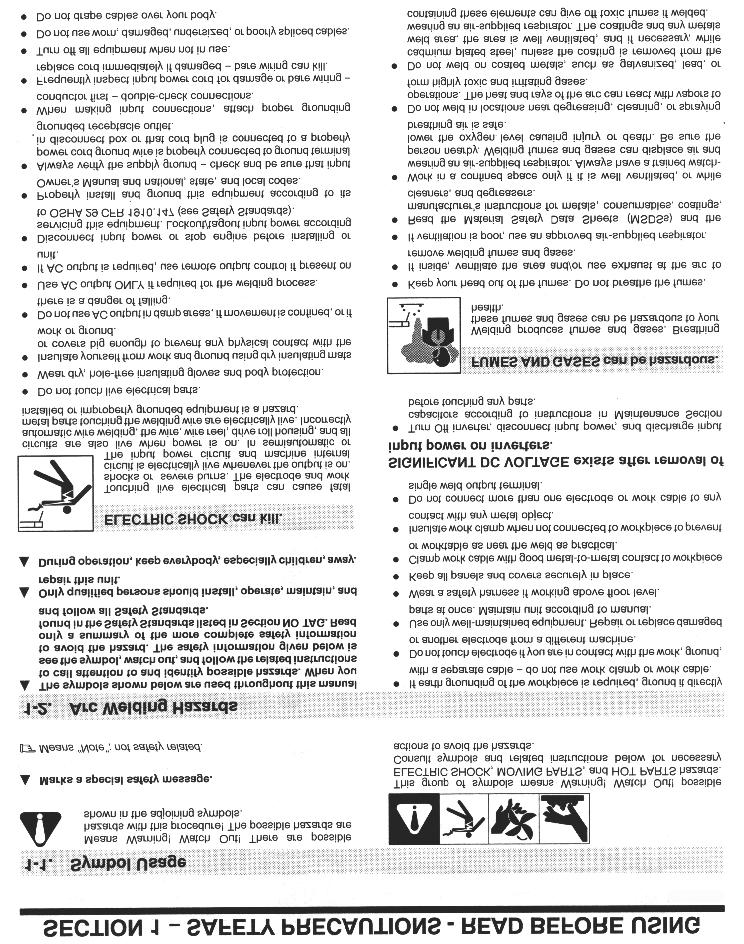
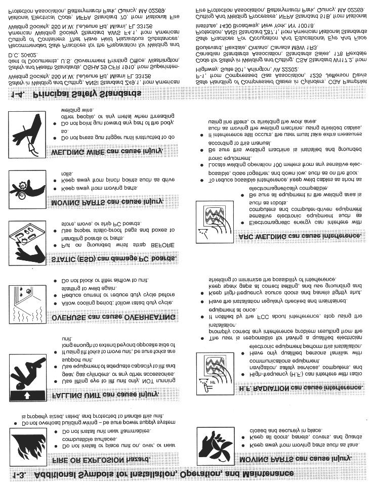
9 1.0 INTRODUCTION Your new stud welding equipment is carefully constructed of the finest components and materials available. Used properly, this equipment will give you years of profitable, efficient service. The system incorporates the latest in engineering advances, for completely reliable end welding of mild steel, stainless steel, aluminum and lead free copper and brass fasteners. A careful study of this manual will enable you to understand how the welder operates to insure proper performance under all operating conditions. 2.0 WARRANTY The electrical and mechanical components of the stud welder are thoroughly performance inspected prior to assembly in the welder. The assembled welder is completely performance checked. The welder is delivered to you in functional electromechanical condition. All parts used in the assembly of the welder and its accessories are fully warranted for a period of 1 YEAR from the date of delivery. In addition, the welding capacitors are warranted for a period of 1 YEAR from the date of delivery. The printed circuit boards used in all proweld equipment are warranted for a period of 3 years. Under the warranty, the manufacturer reserves the right to repair or replace, at their option, defective parts which fail during the guarantee period. Notice of any claim for warranty repair or replacement must be furnished to the manufacturer by the purchaser within ten (10) days after the defect is first discovered. The manufacturer does not assume any liability for paying shipping cost or any labor or materials furnished where such cost are not expressly authorized in writing. The manufacturer does not warrant any parts or accessories against failures resulting from misuse, abuse, improper installation, maladjustment, or use not in accordance with the operating instructions furnished by the manufacturer. The warranty is valid only when studs are purchased from sources approved by the manufacturer or are of identical specifications to the manufacturer s 3.0 UNPACKING YOUR UNIT Upon receipt of your unit, place it as close as possible to the point of installation before unpacking it. Do not operate the unit from an extension power cord if possible. Once the unit is unpacked it is recommended that you inspect it for any physical damage. Your unit has been completely assembled and inspected at the factory. Upon receipt, the unit must be hooked up to the recommended incoming power before welding. We recommend that you check that you have received all the items listed on the shipping check list. (see SECTION 18 or 19) Place the unit in a large enough area to provide adequate ventilation. Do not restrict the air flow through the side louvers. Do not allow water to enter the control housing. 4.0 SUGGESTED SAFETY PRECAU- TIONS In any welding operation, it is the responsibility of the welder to observe certain safety rules to insure his personal safety and to protect those working near him. Reference is directed, without endorsement or recommendation, to ANSI Z49.1, Safety in Welding and Cutting, and to AWG Publication A6,1-66, Recommended Safety Practices for Gas-Shield Arc Welding. 1. Always treat electricity with respect. Under open circuit conditions, the welding machine output voltage may be dangerous. 2. Don t work on live circuits or conductors. Disconnect the main power line before checking the machine or performing any maintenance operations. 3. Be sure the welding machine cabinet is properly grounded to a good electrical ground. 4. Don t stand in water or on a damp floor while welding or weld in the rain. Avoid wearing wet sweaty cloths when welding. Page 1
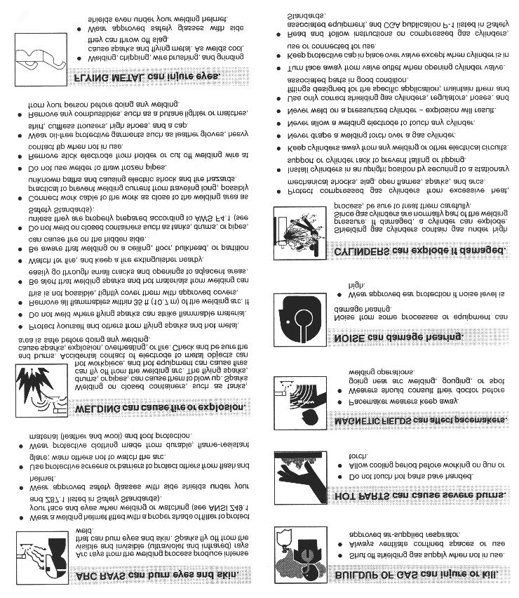
10 5. Don t operate with worn or poorly connected cables. Don t operate weld gun with loose cable connections. Inspect all cables frequently for insulation failures, exposed wires, loose connections, and repair as needed. 6. Don t overload welding cables or continue to operate with hot cables. 7. Don t weld near flammable materials or liquids, in or near atmospheres, or on ducts carrying explosive gases. 8. Don t weld on containers which have held combustible or flammable materials, or on materials which give off flammable or toxic vapors when heated, without proper cleaning, purging, or inerting. 9. Be sure to provide for proper ventilation when welding in confined spaces. 10. Never look at the electric arc without wearing protective eye shields. 11. Always use the proper protective clothing, gloves, ect. The system comes complete with power cord, weld cables and gun. Just add the accessories required for the stud size to be welded. This manual should provide all the information required for you to be able to set up, weld, and maintain the CD-212 welding system. 6.0 THE CD ING PROCESS Contact welding is the simplest and most common method of CD stud welding. Practically foolproof, it produces no reverse side marking in most cases and is suitable for most commercial and industrial applications. First, the gun must be set-up with the proper accessories for the length and diameter stud you are going to weld. Refer to the CD Accessories Guide and CD Stud Welding Gun Section for information on accessories and gun set-up. 1 2 Initial Contact During Weld Never strike an arc when near a bystander who is unaware of the dangers of ultraviolet light on their eyes. Forced Into Molten Pool After Weld 5.0 GENERAL DESCRIPTION CD-212 HEAVY DUTY PORTABLE CD STUD/PIN ER The CD-212 portable CD welder is a self contained heavy duty capacitor discharge power supply capable of welding up to 1/4 flanged studs in mild steel. The CD-212 utilizes a solid state control board for longer life and has been designed for easy maintenance and field service. This welder uses standard 110 volt AC line voltage. (FIGURE 1 CONTACT CD ) The stud is first placed in contact with the base material (SEE FIGURE 1). Verify that the gun is held perpendicular to the work. Pulling the trigger discharges the capacitors through the stud which vaporizes the tip. The proper tip design is critical. This is what determines the length of time of the weld. An arc is briefly sustained which melts the stud base surface and the work surface directly underneath the stud. The spring pressure in the gun then forces the stud into the molten pool, completing the weld in approximately six milliseconds. Page 2
11 This technique, when equipment is set up properly, is simple and easily mastered. The same power supply is capable of welding many different sizes and materials of fasteners. If you require assistance in selecting the proper accessories, contact our customer service department or your field representative. 7.0 POWER REQUIREMENTS 110 VOLT OPERATION 110 volt AC 60 H: 20 amps; Circuit protection: Integral 9 foot power cord IF EXTENSION REQUIRED Cable Length 110 Volt 12 #16/3 25 #16/3 30 #14/3 50 #12/3 15 amp circuit breaker (P/N: ) 8.0 SYSTEM SPECIFICATIONS Weight: 26 Lbs. Size: 9 W x 11 3/4 D x 8 1/2 H 22.9 cm W x 29.8 cm D x 21.6 cm H Chassis: 14 Ga. Aluminum (Painted International Orange) Panel Controls: Power Voltage Controls Weldable Materials: Steel, Stainless steel, Aluminum, Copper, Brass, Zinc coated, Galvanized Weldable Stud Diameter: 14 Ga. Through 1/4 Flanged (Max W.B. Dia. For AL=5/16 (1/4 thread) Weld Rate: 12 per minute Weld Voltage: VDC Weld Mode: Contact Polarity: Straight or Reverse Power Required: 110 Volt AC 60 Hz 20 Amp Circuit Protection: 15 Amp circuit breaker 3AG 1 Amp 250 volt fuses (2 on PC Board) STANDARD GUN & CABLE SPECIFICATIONS GUN-LIGHT DUTY PRECISION CD CONTACT Part Number: B Collet Gun Taper Tip Gun Weight: 2 lbs. (not including cable) ( lbs. (including 25 ft. #4 weld cable & 16-4 SOW control cable) Size: 6 1/2 x 5 3/4 x 2 Weldable Stud Diameter: 14 Ga. Through 1/4 Flanged Material: High strength, impact resistant, glass fiber reinforced polycarbonate Integral Gun Cable Length: 25 feet #4 AWG Connectors: Male Camlok / 2 Pin Hubbell Male Cables Ground Cable: (1) #4 x 15 (P/N: ) Page 3
12 9.0 ING SYSTEM HOOK-UP 9.1 Straight Polarity (Standard Set-Up) (see Figure 2) A. Connect ground cable connector (1A) into camlok (1). The camlok should be connected into the receptacle marked GROUND. Twist until it locks. Attach C clamp (2) to the workpiece (5) (CLEANED AREA). B. Connect the gun control cable (3A) into the female receptacle (3). C. Connect the gun weld cable (4A) into the receptacle marked GUN (4). Twist clockwise until it locks. D. Connect AC power cable to AC outlet. NOTE: The gun welding and control cables must be laid out in a straight line. Poor weld quality may result if welding cables are coiled A 4A 3A 2 Figure 2 Straight Polarity Hook-Up Page 4
13 9.2 Reverse Polarity (Recommended for brass or galvanized) (see Figure 3) A. Connect ground cable connector (1A) into camlok (4). The camlok should be connected into the receptacle marked GUN. Twist until it locks. Attach C clamp (2) to the workpiece (5) (CLEANED AREA). B. Connect the gun control cable (3A) into the female receptacle (3). C. Connect the gun weld cable (4A) into the receptacle marked GROUND (1). Twist clockwise until it locks. D. Connect AC power cable to AC outlet. NOTE: The gun welding and control cables must be laid out in a straight line. Poor weld quality may result if welding cables are coiled A 1A 3A 2 Figure 3 Reverse Polarity Hook-Up Page 5
 and a variable voltage control dial (2) on the front panel. 3.")
14 10.0 SYSTEM OPERATION (see Figure 4) 1. The CD-212 is designed for simple, yet precise operation. 2. It has an ON-OFF rocker switch/indicator light (1) and a variable voltage control dial (2) on the front panel. 3. Before turning the unit ON, the voltage control knob (2) should be turned counter-clockwise to the lowest setting. 4. With all cables connected, turn the unit on by putting the rocker switch (1) in the ON position. The integral indicator light (1) will turn on. Setting the Weld Voltage/Capacitance 2 1 Figure 4 Front Panel Layout Slowly turn the voltage control knob clockwise to increase the weld voltage until the indicator knob is pointing at the appropriate number for the particular stud size that you are welding. (See the set up information chart, Below). NOTE: Once the voltage control knob is set to a higher setting, turning it counter-clockwise will NOT reduce the voltage on the capacitor bank, until the toggle switch (1) is turned OFF (for approximately 10 seconds). The settings are marked with the voltages corresponding to various stud sizes. The approximate voltages for each stud size is as follows: 45 VDC Min VDC 12 ga./# VDC # VDC # VDC 1/4 200VDC MAX. Page 6
15 11.0 GUN SET-UP 11.1 STANDARD (see Figure 5) The standard gun set-up is used for welding the majority of applications. It consists of the standard adjustable face plate, two legs, a foot, B-collet, stop, and spring for your specific stud size. A step-by-step explanation of the correct way to set-up and operate the standard CD gun. To prepare for stud welding, it is necessary to have the proper accessories for the stud to be welded. Those required are the legs, footpiece, spring, collet, and appropriate screws and washers. A 3/32 and a 5/32 hex wrench are the only tools needed for the adjustment of the gun. Figure 5 Standard Gun Setup For CD welding, the stud normally should be engaged for all but 1/4 of its length, whenever possible. Selecting the proper stop will accomplish this for you. The objective of the collet is to maintain a firm grip on the fastener to assure correct alignment and a good electrical connection, yet allow for ease of loading. Once the selection of the correct accessory is made, assembly may begin. The footpiece is mounted on the legs using x 3/4 socket head cap screws, inserted through the holes at the base of the footpiece. These holes are recessed so that the head of the screws will not protrude. After assembling the legs and footpiece, insert the collet and stop into the open end of the gun shaft. Secure the collet in place with two set screws on the shaft. Locate the legs, with footpiece attached, in the holes provided in the gun faceplate. (It may be necessary to back off the socket screw in the faceplate to allow the legs to enter the hole). Center the opening of the footpiece around the weld end of the fastener. Tighten the footpiece in position at this time. Adjustment for the plunge which is the distance the stud protrudes beyond the end of the footpiece can now be made. This is done by loosening the two x 1/4 set screws at the bottom of the faceplate using the 3/32 Allen wrench. Then sliding the legs for proper adjustment. Refer to the set-up chart for correct plunge distance (from 1/8 to 5/16 ). NOTE: Correct set-up on all CD units is 1/8-5/16 plunge. This must be assured for proper weld results in all cases. Page 7

16 The gun is now ready to weld. Select the proper setting for the size stud to be welded. Voltage is determined by the weld base diameter. Be sure your power source is set for the proper polarity: straight for steel, reverse for galvanized INSTALLING OR CHANGING COLLETS OR CHUCKS ( The terms collet or chuck are different names for the same device). The collet holds the pin or stud to be welded. It is secured to the gun shaft by two set screws. These screws are loosened to remove or replace a collet. Tighten these screws snugly to secure the collet in place. When you change the size of the stud you are welding, you must also change to the appropriate collet. If a collet becomes damaged or broken, it must be replaced. You may also need a stop GUN SET-UP FOR PINS WITH COLLET PROTECTOR (see Figure 6) The collet protector has several advantages over the standard set-up. 1. It does not require a pin stop. therefore, the same setup is applicable for a range of pin lengths. 2. There is a fixed plunge, no gun adjustments necessary. 3. It provides stability at the weld end of the pin. There are two standard sizes available: 12 ga. And 10 ga. It is used with the round faceplate and three blunt legs. The collet protector slides over the collet and fastens to the chuck with three allen set screws. The insert, which takes the place of the Interal stop, is replaceable. The stud is pushed into the chuck until the flange bottoms out on the insert. The collet protector is not available for studs larger than 10 ga. The standard adjustable legs and footpiece combination can alternately be used with the collet protector as shown in Figure 10. Figure 6 Collet Protector Gun Setup Page 8

17 11.4 TEMPLATE ADAPTER (see Figure 7) The template adapter is used when precise location or positioning of the CD stud is required. It is used with the round faceplate and does not require a footpiece or legs. The adapter is fastened to the faceplate and provides a fixed distance between the collet and work. The plunge is set by using the correct stop in the collet. A template can then be fabricated to enable very precise locating of a particular stud COLLET PROTECTOR/BLUNT LEG (see Figure 8) The round faceplate, with blunt legs, can alternately be used with the collet protector as shown in Figure 8. The template adapter is available in two sizes, (1 and 1-1/4 diameter). Figure 8 Collet Protector/Blunt Leg Setup Figure 7 Template Adapter gun setup Page 9
18 Figure 9 Light Duty CD Gun Page 10
19 11.6 PARTS LIST LIGHT DUTY CD HANDGUN Part No ITEM PART NO. DESCRIPTION QTY GUN (CD) REAR CAP MOLDED SPRING MAIN HEAVY SILVER GUN (CD/DA) BEARING ASSEMBLY GUN (CD) SHAFT TUBE HEX HEAD CAP SCREW GUN (CD/DA/FA) TRIGGER SPRING M SCREW SET MS, BRASS PLT 2 8 NOT USED GUN (CD/DA/FA) CABLE CLAMP (ALUM. BLOCK) TRIGGER SWITCH GUN (CD/DA/FA) TRIGGER BUTTON MOLDED GUN (FL) SHAFT BLOCK A GUN CABLE (25 FT.) GUN CONTROL CABLE (25 FT.) GUN BODY RH & LH STD.CD MACHINED GUN (CD/FL) SHAFT BOOT ASSY GUN (CD) SHAFT BOOT RETAINING RING GUN (CD) FACEPLATE STD. ADJUSTABLE GUN (CD) SHAFT BOOT SNAP RING GUN (CD) PIGTAIL ASSY SCREW PAN HEAD WASHED, LOCK INTO. TOOTH LEG (CD) STD.ADJ. 7 2 REF FLAT WASHER 2 REF SOCKET HEAD CAP SCREW 2 REF STD. FOOTPIECE 1 REF. Page 11
20 12.0 ABLE MATERIAL COMBINATIONS BASE MATERIAL STUD MATERIALS Mild Steel ( ) Mild Steel 1008, 1018 Stainless Steel 304, 305 Brass 65-35, Copper, Silicon/Bronze Galvanized Sheet (duct- Q Decking Mild Steel Stainless Steel 304,305 Structural Steel (Must Be Clean) Mild Steel 1008,1018 Stainless Steel 304,305 Brass 65-35, Aluminum Most alloys of the Aluminum 1100, , 3000 and 5000 series. Zinc Alloys (Die Cast) Aluminum 1100, 5356 Medium Carbon Steel ( ) Mild Steel 1008, 1018 Stainless Steel 304,305 Brass 65-35, Lead Free Brass Mild Steel 1008, 1018 Lead Free Rolled Brass Stainless Steel 304, 305 Electrolytic Copper Copper, Silicon/Bronze Page 12
21 13.0 CAUSE OF POOR OR ERRATIC S 1. Loose collet. Does not grip stud tightly. (REPLACE) Not enough engagement of stud to collet. (CHANGE STOP) 2. Fault or loose ground connection. (REPAIR OR TIGHTEN) 12. Incorrect spring. (REPLACE WITH PROPER SPRING) 13. Poor stud quality TROUBLE SHOOTING POOR S 3. Poor surface condition of base material, excessive oil, grease, rust, ect. (CLEAN) 4. Voltage or capacitance setting too low or too high. (ADJUST TO DIAMETER OF STUD) 5. Broken or loose cables. (REPAIR) 6. Dirt in gun. (CLEAN) 7. Incorrect polarity. (CABLES HOOKED-UP WRONG) 8. Use of center punch or deep scribe. (DO NOT USE CENTER PUNCH OR DEEP SCRIBES) Figure 10 Weld too Hot Weld too Hot A) Decrease voltage. B) Decrease capacitance. C) Increase stud protrusion. D) Increase spring pressure. 9. Cables too closely coiled. 10. Arc blow is evidenced by one side welds. In severe cases there will be no melting under one edge of flange while the opposite side is gouged out or appears excessively hot. The principle cause of arc blow is magnetic field induced by the current flow during the weld. It occurs most often on long, narrow strips of metal or near edges of sheets or plates. In some cases, a change in grounding positions, or two grounds on the work piece, one at each end or edge of work, will correct the problem. For assistance in severe cases, contact your local sales representative. 11. Incorrect plunge setting. (ADJUST TO PROPER SETTING) Figure 11 Weld too Cold Weld too Cold A) Increase voltage. B) Increase capacitance. C) Decrease stud protrusion. D) Decrease spring pressure. Page 13
22 15.0 ROUTINE ER MAINTENANCE Your CD-212 is designed for long service with minimum care. Ordinary common sense maintenance will keep it operating efficiently. Arc Blow Figure 12 Arc Blow A) Use double grounds. B) Ground too close or not spaced 1. Treat the welding, ground, and control cables with respect. Avoid sharp bends and kinks which may break the cables. Don t use the cables as a tow line to move the control. Avoid damage or straining the cables where they enter the gun or at the connectors. 2. It is good practice to occasionally remove the cover of the controller and clean with air and a soft brush around the components. Figure 13 Weld without footpiece CAUTION Be sure the controller is disconnected from the power before removing the protective cover. Weld without footpiece A) Use standard footpiece. B) Use template adapter. C) Use tripod blunt legs. 3. While the cover is removed, tighten all the weld cable connections and make sure all the screws on the capacitor terminals are torque to 30 inchpounds. NOTE: Keep the gun free of dust, dirt or foreign material Figure 14 Good Weld Page 14
 106-0023 5 Transformer 105-0017 6 PC Board 600-0013 7 Discharge Resistor 112-0041 8 Safety Discharge SCR 108-0042 9 Charging SCR 108-0002 10 Buss Bar 124-0034 11 Diode")
23 16.0 ASSEMBLY CD-212 CONTROLLER (see Figure 15,16, & 17) 13a Figure 15 Parts List ITEM DESCRIPTION PART NUMBER 1 Chassis SCR Mounting Main SCR Capacitor (3) Transformer PC Board Discharge Resistor Safety Discharge SCR Charging SCR Buss Bar Diode Charging Bridge Buss Bar a 150K 2 Watt Page 15
24 Figure 16 Parts List ITEM DESCRIPTION PART NUMBER 14 Knob Female Camlok (2) Pole Female Hubbell Power Switch Circuit Breaker Page 16
25 16.1 PC BOARD ASSEMBLY DRAWING FU1 and FU2 are 3AG 1 ampere fuses C4 R23 + ZD1 R10 R8 V4 C2 C1 R11 R7 V1 R6 R9 R13 V6 + R21 R22 R20 R25 + C8 D9 C7 R15 D7 R14 ZD2 C6 + V5 OP1 R24 R17 D6 R16 R18 OP3 R26 R19 C5 + D5 D4 R5 R4 D2 D1 OP2 D10 D11 V3 R12 R3 D3 R2 D12 D13 V2 C3 D8 R1 F2 F1 Figure 17 PC Board Page 17
26 17.0 TROUBLE SHOOTING ELECTRICAL When troubleshooting the power unit/controller (welder), the following precautions must be observed: 1. Welder must be TURNED OFF! 2. Unplug power cable from welder and wait at least two minutes before checking components. 3. The use of a volt/ohmmeter is recommended where any voltage may be present. 4. Use a continuity tester ( or troubleshooting light) for continuity checks only. 5. Possible causes marked with a star (*) are generally the most common problems. PROBLEM POSSIBLE CAUSE CORRECTIVE ACTION 1. Welder does not turn on A. Power connections at Check connections. and will not weld. Welder or 110 VAC outlet not complete. *B. Broken power cable or loose wire connection in the plug. Check wires for continuity. Repair break. C. Fuse blown. Replace fuse. 2. Fuse blows each time *A. Shorted weld capacitor. Check safety vent seal for unit is turned on. Rupture hole. Replace defective capacitor. B. Shorted rectifier (BR1) Check for a short across the rectifier with ohmmeter. Replace rectifier module if shorted. C. Incorrect primary hookup. Check transformer connections. D. Shorted transformer Replace transformer. assembly. Page 18
27 PROBLEM POSSIBLE CAUSE CORRECTIVE ACTION 3. Welder turns on but A. Ground cable connections Check for continuity does not operate not complete. *B. Broken gun control cable or loose wire connection in the plug. Shorted or open trigger switch. *C. Faulty printed circuit board. Check continuity between pins on control plug while trigger is depressed. Should read continuity. Replace with new PC Board. D. Shorted weld SCR. Check with ohmmeter (should not show continuity in either direction). Replace rectifier module if shorted. 4. Weld is excessively hot A. Shorted charge SCR. Check with ohmmeter regardless of voltage ( should not show continuity setting. In either direction). Replace if shorted. *B. Faulty printed circuit board. Replace with new PC Board. C. Open voltage Replace defective voltage potentiometer. Potentiometer. 5. Poor and erratic A. Improper gun setup. Check applicable gun setup welding. Instruction page. B. Improper grounding or Check applicable cable setup cable setup or incorrect Instruction page. polarity. C. Weld cables are coiled. Straighten out cables. D. Incorrect voltage setting. Adjust as necessary. E. Studs or pins not Adjust legs as necessary. perpendicular to work Replace defective legs. surface. Page 19
28 18.0 CHECK LIST CD-212 SYSTEM PT. NO STANDARD CD-212 ING SYSTEM COMPLETE WITH B-COLLET GUN AND 25 #4 GROUND CABLE ITEM DESCRIPTION PART # QTY 1. CD-212 CONTROLLER 110 VAC GUN ASSY. B-COLLET w/integral 25 FT. & CONTROL CABLE 2-LEGS, and FOOTPIECE GROUND CABLE #4 X MANUAL, Operation and Maintenance CD HEX WRENCH SET CHECK LIST CD-212 SYSTEM PT. NO STANDARD CD-212 ING SYSTEM COMPLETE WITH TAPER TIP GUN AND 25 #4 GROUND CABLE ITEM DESCRIPTION PART # QTY 1. CD-212 CONTROLLER 110 VAC GUN ASSY. TAPER TIP w/integral 25 FT. & CONTROL CABLE 2-LEGS, and FOOTPIECE GROUND CABLE #4 X MANUAL, Operation and Maintenance CD HEX WRENCH SET 1 Page 20
29
30 MANUFACTURED BY PRO MADE IN THE U.S.A.
OPERATION/ MAINTENANCE MANUAL
 OPERATION/ MAINTENANCE MANUAL TABLE OF CONTENTS 1.0 INTRODUCTION 1 2.0 WARRANTY 1 3.0 UNPACKING YOUR UNIT 1 4.0 SUGGESTED SAFETY PRECAUTIONS 1 5.0 GENERAL DESCRIPTION 2 6.0 THE CD ING PROCESS 2 7.0 POWER
Cutlass Fasteners, Inc. 83 Vermont Ave., Unit 6, Warwick, RI Tel: (401) Fax: (401) cutlass-studwelding.com
 Fax: (401) cutlass-studwelding.com") MODEL : BANTAM C8 PART NO. : 602-325P SERIAL NO. : PLEASE READ THIS OPERATION AND MAINTENANCE MANUAL CAREFULLY BEFORE USING YOUR NEW CUTLASS STUD WELDER. COPYRIGHT CFI 2009 email: sales@ PAGE - 1 - WARRANTY
MODEL : BANTAM C8 PART NO. : 602-325P SERIAL NO. : PLEASE READ THIS OPERATION AND MAINTENANCE MANUAL CAREFULLY BEFORE USING YOUR NEW CUTLASS STUD WELDER. COPYRIGHT CFI 2009 email: sales@ PAGE - 1 - WARRANTY
Cutlass Fasteners, Inc. 83 Vermont Ave., Unit 6, Warwick, RI Tel: (401) Fax: (401) cutlass-studwelding.com
 Fax: (401) cutlass-studwelding.com") MODEL : BANTAM C8 BANTAM C10 PART NO. : 602-325A 602-343A SERIAL NO. : PLEASE READ THIS OPERATION AND MAINTENANCE MANUAL CAREFULLY BEFORE USING YOUR NEW CUTLASS STUD WELDER. COPYRIGHT CFI 2009 email: sales@
MODEL : BANTAM C8 BANTAM C10 PART NO. : 602-325A 602-343A SERIAL NO. : PLEASE READ THIS OPERATION AND MAINTENANCE MANUAL CAREFULLY BEFORE USING YOUR NEW CUTLASS STUD WELDER. COPYRIGHT CFI 2009 email: sales@
ARC 1850 LIST OF FIGURES
 PAGE 1.0 INTRODUCTION... 1 2.0 WARRANTY... 1 3.0 UNPACKING YOUR UNIT... 1 4.0 SUGGESTED SAFETY PRECAUTIONS...... 1 4.1 PERSONAL SAFETY PRECAUTIONS. 1 4.2 POWER SUPPLY SAFETY PRECAUTIONS.. 2 5.0 GENERAL
Cutlass Fasteners, Inc. 83 Vermont Ave., Unit 6, Warwick, RI Tel: (401) Fax: (401) cutlass-studwelding.com
 Fax: (401) cutlass-studwelding.com") MODEL : PHM-10 SHORT CYCLE WELD GUN PART NO. : PHM-10 SERIAL NO. : PLEASE READ THIS OPERATION AND MAINTENANCE MANUAL CAREFULLY BEFORE USING YOUR NEW CUTLASS STUD WELDER. COPYRIGHT CFI 2009 email: sales@
MODEL : PHM-10 SHORT CYCLE WELD GUN PART NO. : PHM-10 SERIAL NO. : PLEASE READ THIS OPERATION AND MAINTENANCE MANUAL CAREFULLY BEFORE USING YOUR NEW CUTLASS STUD WELDER. COPYRIGHT CFI 2009 email: sales@
OPERATION/ MAINTENANCE MANUAL
 208 VERSION OPERATION/ MAINTENANCE MANUAL TABLE OF CONTENTS Section 1 SAFETY PRECAUTIONS PAGE 1.0 INTRODUCTION... 1 2.0 WARRANTY... 1 3.0 UNPACKING YOUR UNIT... 1 4.0 SUGGESTED SAFETY PRECAUTIONS... 1
OPERATION/ MAINTENANCE MANUAL
 OPERATION/ MAINTENANCE MANUAL TABLE OF CONTENTS PAGE 1.0 INTRODUCTION... 1 2.0 WARRANTY... 1 3.0 UNPACKING YOUR UNIT... 1 4.0 SUGGESTED SAFETY PRECAUTIONS...... 1 4.1 PERSONAL SAFETY PRECAUTIONS. 1 4.2
TABLE OF CONTENTS LIST OF FIGURES
 TABLE OF CONTENTS Section 1 SAFETY PRECAUTIONS PAGE 1.0 INTRODUCTION... 1 2.0 WARRANTY... 1 3.0 UNPACKING YOUR UNIT... 1 4.0 SUGGESTED SAFETY PRECAUTIONS... 1 4.1 PERSONAL SAFETY PRECAUTIONS 1 4.2 POWER
OPERATION/ MAINTENANCE MANUAL
 OPERATION/ MAINTENANCE MANUAL TABLE OF CONTENTS Section 1 SAFETY PRECAUTIONS PAGE 1.0 INTRODUCTION... 1 2.0 WARRANTY... 1 3.0 UNPACKING YOUR UNIT... 1 4.0 SUGGESTED SAFETY PRECAUTIONS... 1 4.1 PERSONAL
Cutlass Fasteners, Inc. 83 Vermont Ave., Unit 6, Warwick, RI Tel: (401) Fax: (401) cutlass-studwelding.com
 Fax: (401) cutlass-studwelding.com") MODEL : PINTO YTEM/PKM-1B GUN PART NO. : C-1K ERIAL NO. : PLEAE READ THI OPERATION AND MAINTENANCE MANUAL CAREFULLY BEFORE UING YOUR NEW CUTLA TUD WELDER. COPYRIGHT CFI 2009 email: sales@ PAGE - 1 - WARRANTY
MODEL : PINTO YTEM/PKM-1B GUN PART NO. : C-1K ERIAL NO. : PLEAE READ THI OPERATION AND MAINTENANCE MANUAL CAREFULLY BEFORE UING YOUR NEW CUTLA TUD WELDER. COPYRIGHT CFI 2009 email: sales@ PAGE - 1 - WARRANTY
OPERATION MANUAL MODELS TWE-250 TWE-321 TWE-375 TRU WELD EQUIPMENT COMPANY 6400 N. HONEYTOWN ROAD SMITHVILLE, OHIO (330)
") OPERATION MANUAL MODELS TWE-250 TWE-321 TWE-375 TRU WELD EQUIPMENT COMPANY 6400 N. HONEYTOWN ROAD SMITHVILLE, OHIO 44677 (330) 669 2773 CONTENTS Section Description Pages 1 Introduction 3 2 External Features
OPERATION MANUAL MODELS TWE-250 TWE-321 TWE-375 TRU WELD EQUIPMENT COMPANY 6400 N. HONEYTOWN ROAD SMITHVILLE, OHIO 44677 (330) 669 2773 CONTENTS Section Description Pages 1 Introduction 3 2 External Features
OPERATOR S MANUAL StudPro LiteXI Pin Welder Stud Welding Products, Inc
 OPERATOR S MANUAL StudPro LiteXI Pin Welder CONTENTS Description Pages Safety 2 Specifications and Features 3 Product Components 4-5 Screen Operation 6-8 Setup and Welding 9-11 CD Gun Exploded View 12
OPERATION MANUAL MODELS TWE-250 TWE-321 TWE-375 TRU WELD EQUIPMENT COMPANY 6400 N. HONEYTOWN ROAD SMITHVILLE, OHIO (330)
") OPERATION MANUAL MODELS TWE-250 TWE-321 TWE-375 TRU WELD EQUIPMENT COMPANY 6400 N. HONEYTOWN ROAD SMITHVILLE, OHIO 44677 (330) 669 2773 Version 1.3 Date 10/20/2010 TRU WELD EQUIPMENT LIMITED WARRANTY All
OPERATION MANUAL MODELS TWE-250 TWE-321 TWE-375 TRU WELD EQUIPMENT COMPANY 6400 N. HONEYTOWN ROAD SMITHVILLE, OHIO 44677 (330) 669 2773 Version 1.3 Date 10/20/2010 TRU WELD EQUIPMENT LIMITED WARRANTY All
STUD WELDING EQUIPMENT & ACCESSORIES CATALOG
 STUD WELDING EQUIPMENT & ACCESSORIES CATALOG WWW.PROWELDINTERNATIONAL.COM 129 COMMERCE DR LAGRANGE, OH. 44050 PHONE: (440)-355-6064 FAX: (440)-355-6474 07/01/02 CD WELDING SYSTEMS PART # LIST PRICE CD-212
OPERATOR S MANUAL STUDPRO SERIES
 OPERATOR S MANUAL STUDPRO SERIES Capacitor Discharge Stud Welder MODELS: StudPro 2500XI StudPro 2500XIP StudPro 3125XI StudPro 3750XI CONTENTS Description Pages Safety 2 Specifications and Features 3 Product
OPERATION MANUAL TWE-375 CAPACITOR DISCHARGE WELDER
 OPERATION MANUAL TWE-375 CAPACITOR DISCHARGE WELDER TRU WELD EQUIPMENT COMPANY 6400 N. HONEYTOWN ROAD SMITHVILLE, OHIO 44677 (330) 725 7744 TWE@tfpcorp.com Version 1.0 Date 8/13/2013 TRU WELD EQUIPMENT
TOLL FREE
 A Division of TFP Corporation Est. 1928 CD STUD WELDING EQUIPMENT AND ACCESSORIES CATALOG 1 800 727 7883 TOLL FREE www.weldstud.com Sales@weldstud.com 2821 Cole Court Norcross Georgia 30071 (678) 728 0095
CDMF110 PINSPOTTER OWNER S MANUAL MACHINERY DIVISION
 CDMF110 c d m f 1 1 CDMF110 PINSPOTTER OWNER S MANUAL MACHINERY DIVISION UNIT INSTRUCTIONS Please follow all CDMF110 Safety Instructions. Contact your Duro Dyne Tech Service if you have any operating questions.
OPERATION MANUAL. TWE Pin Welder. Model TWP-2 TRU WELD EQUIPMENT COMPANY 6400 N. HONEYTOWN ROAD SMITHVILLE, OHIO (330) Revision 2.
 Revision 2.") OPERATION MANUAL TWE Pin Welder Model TWP-2 TRU WELD EQUIPMENT COMPANY 6400 N. HONEYTOWN ROAD SMITHVILLE, OHIO 44677 (330) 725 7744 Revision 2.0 8/22/2013 TRU WELD EQUIPMENT LIMITED WARRANTY All goods
OPERATION MANUAL TWE Pin Welder Model TWP-2 TRU WELD EQUIPMENT COMPANY 6400 N. HONEYTOWN ROAD SMITHVILLE, OHIO 44677 (330) 725 7744 Revision 2.0 8/22/2013 TRU WELD EQUIPMENT LIMITED WARRANTY All goods
OPERATOR S MANUAL ACE - P100
 OPERATOR S MANUAL ACE - P100 Pin Welder TRU-WELD EQUIPMENT COMPANY www.truweldstudwelding.com (330) 725-7744 CONTENTS Description Pages Warranty Information 1 Safety 2 Specifications and Features 3 Product
OPERATOR S MANUAL. TW-i SERIES. Capacitor Discharge Stud Welder. MODELS: TW-i 250 TW-i 250CP TW-i 321 TW-i 375
 OPERATOR S MANUAL TW-i SERIES Capacitor Discharge Stud Welder MODELS: TW-i 250 TW-i 250CP TW-i 321 TW-i 375 TRU-WELD EQUIPMENT COMPANY www.truweldstudwelding.com (330) 725-7744 CONTENTS Description Pages
CLEAN POWER TM CPS Series Operator s Manual
 12 Test Equipment CLEAN POWER TM CPS Series Operator s Manual Power Supply / Maintenance Charger for 12 Volt Systems The CPS series of power supplies / maintenance chargers are the ultimate in supplying
OPERATION MANUAL. Model TWP-2. Toll free customer support:
 OPERATION MANUAL TWE StudPro Pin Welder Lite Model TWP-2 Downey, CA 9459 Washburn Rd. Downey, CA 90242 Phone- 800.252.1919 Fax- 562.862.3022 Hayward, CA Phoenix, AZ 2391 American TRU WELD Ave. EQUIPMENT
MODEL 7100 PORTABLE PIN WELDER OPERATOR S MANUAL
 Model 7100 Portable Pin Welder MODEL 7100 PORTABLE PIN WELDER OPERATOR S MANUAL Copyright: March 22, 2005 Revised: December 20, 2016 Gripnail Corporation An Employee Owned Company 97 Dexter Road East Providence,
OBE, OBEXU, ON BOARD Battery Chargers
 C O R P O R A T IO N O P E R A T I N G I N S T R U C T I O N S OBE, OBEXU, ON BOARD Battery Chargers INTRODUCTION: These chargers are designed for the permanent installation on battery powered vehicles
QSSE, QSSEX INDUSTRIAL Battery Chargers
 C O R P O R A T IO N O P E R A T I N G I N S T R U C T I O N S QSSE, QSSEX INDUSTRIAL Battery Chargers INTRODUCTION The QSE line are electronically controlled float chargers. The batteries are brought
POWER PINNER CD HAND WELDER 7300 OPERATOR S MANUAL
 POWER PINNER CD HAND WELDER 7300 OPERATOR S MANUAL Copyright: April 7, 2014 Gripnail Corporation Revised: January 25, 2018 An Employee Owned Company 97 Dexter Road East Providence, Rhode Island 02914-2045
Hand Held Capacitor Discharge Welding System. Owner s Manual
 Hand Held Capacitor Discharge Welding System Owner s Manual SureShot II CD Stud Welding System Owner s Manual Installation Operation Maintenance MIDWEST FASTENERS, INC. 450 Richard Street Miamisburg, OH
24 VOLT AUTOMATIC BATTERY CHARGER PART NO
 24 VOLT AUTOMATIC BATTERY CHARGER PART NO. 957732 AC Input: DC Output: Battery Type: Specifications 230 volts, 50 hertz, 3.5 amps, single-phase 24 volts, 20 amps initially tapering to 6 amps 24 volt, 12
QPET, QPETXU Battery Chargers
 C O R P O R A T IO N O P E R A T I N G I N S T R U C T I O N S QPET, QPETXU Battery Chargers INTRODUCTION: The QPET line of chargers are designed for general purpose deep cycle batteries. They are an electronically
LESTRONIC II BATTERY CHARGER TAYLOR-DUNN MODEL TYPE 24LC25-8ET
 LESTRONIC II BATTERY CHARGER TAYLOR-DUNN 79-301-10 MODEL 13110-32 TYPE 24LC25-8ET AC Supply: DC Output: Battery Capacity: Specifications 120 volts, 60 Hertz, single-phase 24 volts, 32 amps Use only on
LESTRONIC II BATTERY CHARGER MODEL 07210
 LESTRONIC II BATTERY CHARGER MODEL 07210 PLEASE SAVE THESE IMPORTANT SAFETY AND OPERATING INSTRUCTIONS For correct operation of the equipment, it is important to read and be familiar with this entire manual
LESTRONIC II BATTERY CHARGER MODEL 19740
 *01679* LESTRONIC II BATTERY CHARGER MODEL 19740 PLEASE SAVE THESE IMPORTANT SAFETY AND OPERATING INSTRUCTIONS For correct operation of the equipment, it is important to read and be familiar with this
POWER PINNER HAND WELDER 7200 OPERATOR S MANUAL
 POWER PINNER HAND WELDER 7200 OPERATOR S MANUAL Copyright: January 5, 2009 Revised: November 24, 2014 Serial No. 0901189 - Gripnail Corporation An Employee Owned Company 97 Dexter Road East Providence,
OBAE, OBAEXU, ON BOARD Battery Chargers
 C O R P O R A T IO N O P E R A T I N G I N S T R U C T I O N S OBAE, OBAEXU, ON BOARD Battery Chargers INTRODUCTION: The OBAE line of chargers are designed for the permanent installation on battery powered
Compressor Duty Motor - 1 HP. Model 40132
 Compressor Duty Motor - 1 HP Model 40132 Assembly and Operating Instructions 3491 Mission Oaks Blvd., Camarillo, CA 93011 Visit our web site at http://www.harborfreight.com Copyright 2002 by Harbor Freight
LESTRONIC II BATTERY CHARGER BUILT-IN OR PORTABLE CHARGERS
 LESTRONIC II BATTERY CHARGER BUILT-IN OR PORTABLE CHARGERS PLEASE SAVE THESE IMPORTANT SAFETY AND OPERATING INSTRUCTIONS For correct operation of the equipment, it is important to read and be familiar
2015 EDITION SUBMERSIBLE MOTORS AIM MANUAL. APPLICATION INSTALLATION MAINTENANCE 60 Hz, Single-Phase and Three-Phase Motors. franklinwater.
 0 EDITION AIM MANUAL SUBMERSIBLE MORS APPLICATION INSTALLATION 60 Hz, Single-Phase and Three-Phase Motors franklinwater.com All Motors System Troubleshooting Motor Does Not Start A. No power or incorrect
AUTOMATIC BURNISHER MODEL FURY 21 HSB
 AUTOMATIC BURNISHER MODEL FURY 21 HSB INTRODUCTION OPERATING & MAINTENANCE INSTRUCTIONS This operator s book has important information for the use and safe operation of this machine. Read this book carefully
36 VOLT AUTOMATIC BATTERY CHARGER PART NO
 36 VOLT AUTOMATIC BATTERY CHARGER PART NO. 957727 AC Supply: DC Output: Battery Type: Specifications 120 volts, 60 Hertz, 10 amps, single-phase 36 volts, 20 amps initially tapering to 6 amps 36 volt, 18
MICRO WELD MODEL AUF-8 HEAVY DUTY FERROUS BUTT WELDERS MICRO PRODUCTS COMPANY SERVICE MANUAL
 MICRO WELD MODEL AUF-8 HEAVY DUTY FERROUS BUTT WELDERS MICRO PRODUCTS COMPANY SERVICE MANUAL 1 TABLE OF CONTENTS 1.0 SPECIFICATIONS 2.0 GENERAL OPERATING INSTRUCTIONS 3.0 BASIC OPERATING PARTS 4.0 BASIC
Lumina 28 Traction Drive Model: Battery Burnisher M28036TDQP OPERATION SERVICE PARTS CARE
 Lumina 28 Traction Drive Model: Battery Burnisher M28036TDQP OPERATION SERVICE PARTS CARE Table of Contents IMPORTANT SAFETY INSTRUCTIONS...1 OPERATING INSTRUCTIONS...2 INSPECTION...2 ELECTRICAL...2 BATTERIES...2
PRODUCT MANUAL TILE CUTTING MACHINE. . Operation. Parts List and Diagram SPECIFICATIONS CAUTION:
 FLORCRAFTT TM PRODUCT MANUAL SKU NUMBER 709-4242 SERIAL NUMBER: CAUTION: FOR YOUR OWN SAFETY READ INSTRUCTION MANUAL COMPLETELY AND CAREFULLY BEFORE OPERATING THIS 7 TILECUTTING MACHINE SPECIFICATIONS
MODEL 6010A 6 12 VOLT BATTERY CHARGER ASSOCIATE
 MODEL 600A 6 VOLT BATTERY CHARGER ASSOCIATE IMPORTANT SAFETY INSTRUCTIONS. SAVE THESE INSTRUCTIONS. This manual contains important safety and operating instructions for the battery charger you have purchased.
ACCUSENSE CHARGE SERIES ON/OFF BOARD FULLY AUTOMATIC BATTERY CHARGER
 ACCUSENSE CHARGE SERIES ON/OFF BOARD FULLY AUTOMATIC BATTERY CHARGER SPECIFICATIONS: *Photo for reference only* Part number 8890439 Mode Select: Selects Battery Type Refer to Section 6. IMPORTANT: READ
Operator s Manual Model AC300 ARC Welder
 Operator s Manual Model AC300 ARC Welder WARNING: Do not assemble, install, or operate this equipment without reading ALL of this manual and the safety precautions and warnings illustrated in this manual.
XENON POWER SUPPLY 4000 Watt Gladiator IV
 XENON POWER SUPPLY 4000 Watt Gladiator IV 220 Volt Equipment Type 62-00049 Rev. February 2003 STRONG INTERNATIONAL a division of Ballantyne of Omaha, Inc. 4350 McKinley Street Omaha, Nebraska 68112 USA
XENON POWER SUPPLY Watt
 XENON POWER SUPPLY 3000-5000 Watt 220 Volt Equipment Type 62-00016 62-00017 62-00004 (Export) Rev. February 2006 STRONG INTERNATIONAL a division of Ballantyne of Omaha, Inc. 4350 McKinley Street Omaha,
MMA 160S ARC/MMA WELDER OPERATION INSTRUCTIONS
 www.r-techwelding.co.uk MMA 160S ARC/MMA WELDER OPERATION INSTRUCTIONS 2 Thank you for selecting the R-Tech MMA160S Inverter Arc Welder. The MMA160S has many benefits over traditional Arc welders, including
Operations & Maintenance Manual DFH-1000 DUCTLESS FUME HOOD
 Operations & Maintenance Manual DFH-1000 DUCTLESS FUME HOOD ----------------------------------------------------------------We Make Clean Air----------------------------------------------------------------
OPERATION INSTRUCTIONS
 www.r-techwelding.co.uk Email: sales@r-techwelding.co.uk Tel: 01452 733933 Fax: 01452 733939 ProArc 175 INVERTER ARC WELDER OPERATION INSTRUCTIONS Version 2017-10 2 3 Thank you for selecting the R-Tech
Maintenance Manual 13 AMPERE POWER SUPPLY 19A704647P1-P3. Mobile Communications LBI-31801C
 C Mobile Communications 13 AMPERE POWER SUPPLY 19A704647P1-P3 CAUTION THESE SERVICING INSTRUCTIONS ARE FOR USE BY QUALI- FIED PERSONNEL ONLY. TO AVOID ELECTRIC SHOCK DO NOT PERFORM ANY SERVICING OTHER
Automatic taper of charge rate for superior battery life through good equalization of cells and low water use rate.
 FEATURES Automatic taper of charge rate for superior battery life through good equalization of cells and low water use rate. Silicon diodes with inherent surge protection operated at a conservative percentage
24/3000H-3PH 24/4500H-3PH 24/6000H-3PH
 Manufacturer of Dimensions TM Inverters 4467 White Bear Parkway St. Paul, MN 55110 Phone: 651-653-7000 Fax: 651-653-7600 E-mail: inverterinfo@sensata.com Web: www.dimensions.sensata.com 120015D OWNERS
MICRO WELD MODEL DP1 & DP2 HEAVY DUTY NON-FERROUS BUTT WELDERS MICRO PRODUCTS COMPANY SERVICE MANUAL
 MICRO WELD MODEL DP1 & DP2 HEAVY DUTY NON-FERROUS BUTT WELDERS MICRO PRODUCTS COMPANY SERVICE MANUAL 1 TABLE OF CONTENTS 1.0 SPECIFICATIONS 2.0 GENERAL OPERATING INSTRUCTIONS 3.0 BASIC OPERATING PARTS
MODEL 6017 OPERATOR'S MANUAL
 MODEL 6017 OPERATOR'S MANUAL ASSOCIATE D IMPORTANT SAFETY INSTRUCTIONS 1. SAVE THESE INSTRUCTIONS. This manual contains important safety and operating instructions for the battery charger you have purchased.
PROCESS ELECTRONICS CORPORATION
 MINIVERTER MANUAL PROCESS ELECTRONICS CORPORATION 100 BRICKYARD ROAD MOUNT HOLLY, NORTH CAROLINA 28120 TELEPHONE (800) 421-9107 FAX (704) 827-9595 SALES@PECRECTIFIER.COM WWW.PECRECTIFIER.COM SOLID STATE
OPERATING INSTRUCTIONS. Note: 6V Charging. Requires Manual Shut Off.
 Requires Manual Shut Off. 6 / 2 AMP,, DUAL RATE BATTER TTERY CHARGER 45005 OPERATING INSTRUCTIONS E224783 E224783 Note: 6V Charging Due to continuing improvements, actual product may differ slightly from
STUD WELDING EQUIPMENT & ACCESSORIES CATALOG NEWPOINT PLACE LAWRENCEVILLE, GA PHONE: (770) FAX: (770)
 FAX: (770)") STUD WELDING EQUIPMENT & ACCESSORIES CATALOG WWW.WELDSTUD.COM 4505 NEWPOINT PLACE LAWRENCEVILLE, GA 30043 PHONE: (770)-962-3657 FAX: (770)-962-3667 6/2008 FERRULE GRIPS CLOSED FERRULE GRIP (1 LONG) BRASS
STUD WELDING EQUIPMENT & ACCESSORIES CATALOG WWW.WELDSTUD.COM 4505 NEWPOINT PLACE LAWRENCEVILLE, GA 30043 PHONE: (770)-962-3657 FAX: (770)-962-3667 6/2008 FERRULE GRIPS CLOSED FERRULE GRIP (1 LONG) BRASS
INSPECTOR LINE LOAD SIMULATOR INSTRUCTION MANUAL TASCO, INC.
 INSPECTOR LINE LOAD SIMULATOR INSTRUCTION MANUAL INS120P TASCO, INC. THIS TESTER IS DESIGNED FOR USE ONLY BY QUALIFIED ELECTRICIANS. IMPORTANT SAFETY WARNINGS mwarning Read and understand this material
Film-Tech. The information contained in this Adobe Acrobat pdf file is provided at your own risk and good judgment.
 Film-Tech The information contained in this Adobe Acrobat pdf file is provided at your own risk and good judgment. These manuals are designed to facilitate the exchange of information related to cinema
AUTO CHARGE D PUMP PLUS
 INSTRUCTION MANUAL AUTO CHARGE D PUMP PLUS AUTOMATIC DUAL OUTPUT BATTERY CHARGER Designed Specifically for Vehicles with DDEC ENGINES MODEL #: 091-9-DPP INPUT: 120 Volt, 60 Hz, 8 Amps OUTPUT VEHICLE BATTERY:
OPERATION MANUAL MODELS TWE-321 TWE-375. Toll free customer support:
 OPERATION MANUAL MODELS StudPro TWE-250 2500i TWE-321 TWE-375 Downey, CA 9459 Washburn Rd. Downey, CA 90242 Phone- 800.252.1919 Fax- 562.862.3022 Hayward, CA Phoenix, AZ 2391 American TRU WELD Ave. EQUIPMENT
1500 & 2000 RPM BURNISHERS
 1500 & 2000 RPM BURNISHERS INTRODUCTION OPERATING & MAINTENANCE INSTRUCTIONS This operator s book has important information for the use and safe operation of this machine. Read this book carefully before
TWE Operations Manual
 HEAVY-DUTY STUD GUN Operations Manual The TWE17000 has been designed to fit comfortably for all hands, including when wearing a work glove. The neck of the handle has been tapered so that when grasped,
The Da-Lite Difference.
 The Da-Lite Difference. Instruction Book for Large Advantage Electrol DA-LITE SCREEN COMPANY, INC. 3100 North Detroit Street Post Office Box 137 Warsaw, Indiana 46581-0137 Phone: 574-267-8101 800-622-3737
SERIES OPERATION AND MAINTENANCE MANUAL
 SERIES OPERATION AND MAINTENANCE MANUAL This manual CONTAINS IMPORTANT WARNINGS, S and OTHER INSTRUCTIONS. Read and understand the instruction manual Carefully, before use and retain it for reference.
ADI-125/750 ADI-125/1500 ADI-125/2500
 Manufacturer of Dimensions TM Inverters 4467 White Bear Parkway St. Paul, MN 55110 Phone: 651-653-7000 Fax: 651-653-7600 E-mail: inverterinfo@sensata.com Web: www.dimensions.sensata.com 121094B OWNERS
DC to AC Power Inverters
 Manufacturer of Dimensions TM Inverters 4467 White Bear Parkway St. Paul, MN 55110 Phone: 651-653-7000 Fax: 651-653-7600 E-mail: inverterinfo@sensata.com Web: www.dimensions.sensata.com ISO 9001:2000 Certified
AUTO CHARGE 12 AUTOMATIC BATTERY CHARGER
 INSTRUCTION MANUAL FILE: 091-165-12 reve Rev: E, page 8 DATE: 7-02-15 AUTO CHARGE 12 AUTOMATIC BATTERY CHARGER MODEL #091-165-12 NOTE : This charger is designed for vehicles with a single battery and negative
MASTERsine Inverter PXA Series Installation Guide
 Backup Power System Expert TM MASTERsine Inverter PXA Series Installation Guide Important Safety Instructions IMPORTANT: Read and save this Installation Guide for future reference. This chapter contains
AUTOMATIC FOODSERVICE EQUIPMENT. AUTOMATIC ELECTRIC BROILER MODELS 824E & 850E and 624E & 650E. B-Series Broiler OWNER S MANUAL
 AUTOMATIC FOODSERVICE EQUIPMENT AUTOMATIC ELECTRIC BROILER MODELS 824E & 850E and 624E & 650E B-Series Broiler OWNER S MANUAL FOR YOUR SAFETY: Do not store or use gasoline or other flammable vapors or
Dimensions 12/800N 12/1200N D. DC to AC Power Inverters. OWNERS MANUAL for Models: OWNERS MANUAL April ISO 9001:2000 Certified Company
 Manufacturer of Dimensions Inverters 4467 White Bear Parkway St. Paul, MN 55110 Phone: 651-653-7000 Fax: 651-653-7600 E-mail: inverterinfo@sensata.com Web: www.dimensions.sensata.com OWNERS MANUAL April
INSTRUCTION MANUAL ANGLE GRINDER PT W
 INSTRUCTION MANUAL ANGLE GRINDER PT50360 4½ INCHES 120V 60Hz 600W 5A 12,000 rpm C US Note : Before operating this tool, read this manual and follow all safety rules and operating instructions. This electric
& OPERATING INSTRUCTIONS
 ELECTRIC WINCH 12 / 24 VOLT DC DW5000 (5000LBs/2272Kg) DW6000 (6500LBs/2727Kg) DW8000 (8000LBs/3663Kg) DW8500 (8500LBs/3863Kg) DW9000 (9000LBs/4091Kg) ASSEMBLY & OPERATING INSTRUCTIONS DW5000 Specification
User s Manual. Automatic Switch-Mode Battery Charger
 User s Manual Automatic Switch-Mode Battery Charger IMPORTANT Read, understand, and follow these safety rules and operating instructions before using this battery charger. Only authorized and trained service
24 Volt - 3/8" Cordless Impact Wrench
 24 Volt - 3/8" Cordless Impact Wrench INSTRUCTION MANUAL Item # 3994040 IMPORTANT SAFETY INSTRUCTIONS WARNING: When using electrical equipment such as this, basic safety precautions should always be followed
WARNING. Electric Recovery Winch. General Safety Precautions
 1 Electric Recovery Winch Thanks for purchasing a WINCH. This manual covers operation and maintenance of the winch. All information in this publication is based on the latest production information available
MPPC40DVI OWNER S MANUAL
 MPPC40DVI OWNER S MANUAL 4/2017 WARNING: Read carefully and understand all ASSEMBLY AND OPERATION INSTRUCTIONS before operating. Failure to follow the safety rules and other basic safety precautions may
A48 / A48B (base plate) BATTERY CHARGER
 BATTERY CHARGER") A48 / A48B (base plate) BATTERY CHARGER CPN41054 ISSUE DATE: 12315-8/98 ECN/DATE 106 BRADROCK DRIVE DES PLAINES, IL. 60018-1967 (847) 299-1188 FAX: (847)299-3061 15349-07-07/02 16041 6/03 14575-2/01 INSTRUCTION
A48 / A48B (base plate) BATTERY CHARGER CPN41054 ISSUE DATE: 12315-8/98 ECN/DATE 106 BRADROCK DRIVE DES PLAINES, IL. 60018-1967 (847) 299-1188 FAX: (847)299-3061 15349-07-07/02 16041 6/03 14575-2/01 INSTRUCTION
MODEL A96 SERIES. 130Vdc Switchmode Utility Rectifier / Battery Charger. Used with LaMarche Power Cage ECN/DATE
 MODEL A96 SERIES 130Vdc Switchmode Utility Rectifier / Battery Charger Used with LaMarche Power Cage CPN112138 ECN/DATE ISSUE DATE: ECN 17010-12/05 106 BRADROCK DRIVE DES PLAINES, IL. 60018-1967 (847)
Bench Top Tube Bender
 Bench Top Tube er User s Manual Electric and manual units s fractional and metric tubing CE compliant 2 Bench Top er User s Manual Contents Safety Instructions... 2 Technical Data... 2 Tubing Data... 3
3000W POWER INVERTER. User Manual
 3000W POWER INVERTER User Manual Posts AC outlets Digital display ON/OFF button Remote control connection port (remote control switch is not included) USB port Two set of heavy duty input cable P a g e
AUTOMATIC FOODSERVICE EQUIPMENT. AUTOMATIC ELECTRIC BROILER MODELS 952E, 932E and 922E OWNER S MANUAL
 AUTOMATIC FOODSERVICE EQUIPMENT AUTOMATIC ELECTRIC BROILER MODELS 952E, 932E and 922E OWNER S MANUAL IMPORTANT: RETAIN THIS MANUAL IN A SAFE PLACE FOR FUTURE REFERENCE. FOR YOUR SAFETY: Do not store or
AUTO-BREEZE Cotton Candy Machine Instruction Manual Model #3052
 Part No. 55147 Revised: August 2004 AUTO-BREEZE Cotton Candy Machine Instruction Manual Cincinnati, OH 45241-4807 USA Safety Precautions Auto-Breeze 2 INTRODUCTION Your Floss Machine warranty is described
AUTO CHARGE D2 MODEL #: AUTOMATIC TRIPLE OUTPUT BATTERY CHARGER INSTRUCTION MANUAL
 INSTRUCTION MANUAL AUTO CHARGE D2 AUTOMATIC TRIPLE OUTPUT BATTERY CHARGER Designed Specifically for Vehicles with DDEC ENGINES MODEL #: 091-74-12 INPUT: 120 Volt, 60 Hz, 8 Amps OUTPUT VEHICLE BATTERY 1
DC to AC Power Inverters
 Manufacturer of Dimensions TM Inverters 4467 White Bear Parkway St. Paul, MN 55110 Phone: 651-653-7000 Fax: 651-653-7600 E-mail: inverterinfo@sensata.com Web: www.dimensions.sensata.com 121114C OWNERS
Alternating Current Revolution per minute Protective Earth Ground. Protected from dripping water Fuse Attention, Consult Accompanying Document
 GLOSSARY OF SYMBOLS: (Symbols and descriptions) Alternating Current Revolution per minute Protective Earth Ground Direct Current On (Power connection Off (power to the mains) disconnection from the mains)
MULTIVOLTAGE PORTABLE BATTERY CHARGER MVM
 _ M MULTIVOLTAGE PORTABLE BATTERY CHARGER MVM User's MANUAL Code: MVM Version: 01-BF Date: OCT 2005 Page 1/10 _ 1. INTRODUCTION Before starting to use your Energic plus MVM battery charger, please take
99 Washington Street Melrose, MA Fax TestEquipmentDepot.com. Instruction Manual. Model 1672 Triple Output Power Supply
 99 Washington Street Melrose, MA 02176 Fax 781-665-0780 TestEquipmentDepot.com Instruction Manual Model 1672 Triple Output Power Supply Contents Section Description Page No. CONTENTS 1 1 TEST INSTRUMENT
XENON POWER SUPPLY Compact Model 220 Volt Equipment Type
 XENON POWER SUPPLY Compact Model 220 Volt Equipment Type 62-80106 62-80108 62-80109 62-80113 Rev. August 2001 STRONG INTERNATIONAL a division of Ballantyne of Omaha, Inc. 4350 McKinley Street Omaha, Nebraska
MIL-24/2600Q MIL-24/3200DQ
 Manufacturer of Dimensions TM Inverters 4467 White Bear Parkway St. Paul, MN 55110 Phone: 651-653-7000 Fax: 651-653-7600 E-mail: inverterinfo@sensata.com Web: www.dimensions.sensata.com 121473B OWNER'S
OWNER S MANUAL SELF-PRIMING PORTABLE UTILITY PUMP
 Model 54011-0 OWNER S MANUAL SELF-PRIMING PORTABLE UTILITY PUMP Questions, problems, missing parts? Before returning to the store call AQUAPRO Customer Service 8 a.m. - 5 p.m., EST, Monday-Friday 1-844-242-2475
OPERATOR'S MANUAL IMPORTANT SAFETY INSTRUCTIONS
 ASSOCIATED OPERATOR'S MANUAL IMPORTANT SAFETY INSTRUCTIONS MODEL 6366 12 VOLT, 0-20 AMP 4 X 20 BATTERY CHARGER 1. SAVE THESE INSTRUCTIONS. This manual contains important safety and operating instructions
O W N E R ' S M A N U A L
 1500 Watt DC to AC Power Inverter C o n v e r t s 1 2 V D C B a t t e r y P o w e r t o 1 1 0 V A C H o m e P o w e r O W N E R ' S M A N U A L SAVE THESE INSTRUCTIONS The recommended source of power is
Cincinnati, OH USA
 Astro Pop Warmer Instruction Manual Model #2002 Part No. 61987 Revised July 2000 Cincinnati, OH 45241-4807 USA e-mail: goldme19@eos.net www.gmpopcorn.com SAFETY PRECAUTIONS INTRODUCTION Your new #2002
1200W Paint DRYING Lamp
 1200W Paint DRYING Lamp Model 97641 Assembly And Operation Instructions Diagrams within this manual may not be drawn proportionally. Due to continuing improvements, actual product may differ slightly from
REDI-LINE. Rugged, Reliable, DC to AC Power Conversion ELECTRIC GENERATORS USER'S GUIDE. KARAM A.L.
 REDI-LINE ELECTRIC GENERATORS USER'S GUIDE Rugged, Reliable, DC to AC Power Conversion KARAM A.L. www.alternatorstarter.com 1-888-515-2726 REDI-LINE ELECTRIC GENERATOR MODEL INPUT ACTUAL OUTPUT ACTUAL
AIR COMPRESSOR OPERATING INSTRUCTION AND PARTS LIST
 AIR COMPRESSOR OPERATING INSTRUCTION AND PARTS LIST BELT TYPE IMPORTANT PLEASE MAKE CERTAIN THAT THE PERSON WHO IS TO USE THIS EQUIPMENT CAREFULLY READS AND UNDERSTANDS THESE INSTRUCTIONS BEFORE STARTING
POLISHERS 17 & 20 DUAL SPEED OPERATING & MAINTENANCE
 POLISHERS 17 & 20 DUAL SPEED MODELS INTRODUCTION OPERATING & MAINTENANCE INSTRUCTIONS This operator s book has important information for the use and safe operation of this machine. Read this book carefully