OPERATION MANUAL MODELS TWE-250 TWE-321 TWE-375 TRU WELD EQUIPMENT COMPANY 6400 N. HONEYTOWN ROAD SMITHVILLE, OHIO (330)
|
|
|
- Jessie Lamb
- 5 years ago
- Views:
Transcription
1 OPERATION MANUAL MODELS TWE-250 TWE-321 TWE-375 TRU WELD EQUIPMENT COMPANY 6400 N. HONEYTOWN ROAD SMITHVILLE, OHIO (330)
2 CONTENTS Section Description Pages 1 Introduction 3 2 External Features Safety Setup and Welding Testing Weld Settings 16 6 Inspecting The Weld 17 7 CD Stud Gun Views 18 8 CD Stud Gun Exploded View 19 9 CD Stud Gun Parts List CD Controller Exploded View CD Controller Parts List 22
3 INTRODUCTION The complete range of the capacitor discharge equipment is compact, portable stud welding equipment. The units are specifically designed to enable a small diameter range of ferrous and nonferrous weld studs to be welded to light gauge metal materials with little or no reverse side marking. The equipment consists of a control unit, a welding hand gun, and all necessary interconnecting cables. THE PROCESS Capacitor Discharge (CD) stud welding is a form of welding in which the energy required for the welding process is derived from a bank of charged capacitors. This stored energy is discharged at the base of the specially designed CD stud and it fuses the stud to the base material. The time of the weld is determined in such a short duration that no burn through marking is made on the finish side of the material. CONTACT In contact CD welding, the stud is placed under spring pressure on the material to be welded. When the capacitors are discharged, the special tip of the CD stud melts and the spring pressure forces the stud to fuse with the base material. GAP In gap CD welding, the stud is placed onto the material to be welded. As the stud gun is engaged, the stud lifts from the base material and then returns to the point of contact at the time of the discharge of the capacitors. As the capacitors discharge, melting the tip of the weld stud, the pressure created by the movement of the stud to the base material by the stud gun fuses the stud to the base material.
4 EXTERNAL FEATURES FRONT PANEL Weld Voltage Selector rotate to change to required voltage. 2. Welding Voltage Digital Display displays selected voltage. 3. LED Lights Charging (capacitors are being charging to desired voltage), Ready (unit is ready to weld), Reset (indicates an error and unit should be turned off). 4. Welding Ground Cable Connector (+) 5. Stud Gun Control Connector 6. Welding Stud Gun Cable Connector ( )
5 EXTERNAL FEATURES REAR PANEL 1.On/Off Switch 2.Fuse Holder (10 amp) 3.AC Power Cord 4.Manufacturer Model Number and Serial Number Plate WARNING! This unit operates from a 110 VAC 60 amp circuit. Do not obstruct the ventilation fan, as this may cause unit to over heat. Do not remove any portion of the unit housing without first disconnecting the unit from the power supply. ON/OFF Switch 15Amp Fuse Power Supply Fan AC Cord

6 SAFETY PROTECT YOURSELF AND OTHERS! Read the safety notices before using welder. ELECTRICAL No portion of the outer cover of the welding controller should be removed by anyone other than qualified personnel. Always disconnect the unit from the main power prior to removing cover. This equipment contains a transformer power supply system, which is energized by AC current and transforms the AC to DC current. Due to potential dangerous electrical input and output the equipment must be disconnected from all incoming power when servicing. Capacitors store electrical energy. Check for residual charge before performing any maintenance. Do not use fluids to clean electrical components as these may penetrate the electrical system and cause shorts. Connection of the unit into service must be in accordance with the setup procedures as detailed in this manual. Operation of this equipment must be in accordance with all local, regional, and national safety codes.
7 SAFETY FIRE During welding, small particles of hot metal can be expelled. Ensure that no combustible materials are near the welding area. FIRE HAZARD FROM SPARKS PERSONAL SAFETY Arc rays can burn your eyes and skin. Wear protective clothing and eye protection when welding. Loud noises from welding can damage hearing. Wear earplugs or other protective gear, if applicable. Fumes and gases expelled during welding can be hazardous to your health. Make sure welding is done in a well ventilated area. Hot metal splatter can cause fires and burns. Wear protective clothing, free of combustible materials. Have a fire extinguisher nearby and know how to use it. MAINTENANCE All cables must be inspected regularly to ensure that no danger exists from worn or damaged insulation or unsafe electrical connections. Take special note to the cables near the stud gun this is where maximum wear occurs. Worn cables not only produce inconsistent welds, but can overheat or spark.

8 SAFETY TRAINING Use of this equipment must be limited to authorized personnel only. They must be adequately trained, and have read and understood everything in this manual. The manual must be available to operators at all times. AUTHORIZED PERSONNEL ONLY INSTALLATION Select a site for the equipment which is capable of supporting the weight of the equipment, which is clear from traffic routes where people may trip over cables, or they may be damaged by other equipment or vehicles. Do not hang connecting cables over sharp edges or have near heat sources. DISPOSAL The equipment, in its entirety or as components/parts may be disposed of as general industrial waste or scrap. None of the components used in the manufacturing of the CD Welders are toxic, carcinogenic, or otherwise harmful to your health.
9 SET-UP AND WELDING POWERING UP THE EQUIPMENT Setup the equipment power supply (Control Unit) and connect to the main power, making certain of the proper voltage requirement of the particular unit. Capacitor Discharge (CD) units generally require Hz incoming power. Refer to the safety recommendations before plugging this unit in. ON/OFF Switch Fuse Power Cord (110 VAC) CONNECTING THE WELDING LEADS Connect the welding ground cable into the (+) terminal mount socket on the front of the welding unit. ***NOTE the cable end plug has a flat which aligns with a dot on the panel mount socket. Secure the connector into the panel mount socket, and then turn it clockwise until it locks into proper position. Failure to do so could result in damage to the connector. Ground Cable Socket
10 SET-UP AND WELDING CONNECTING THE WELDING LEADS Connect the welding stud gun power cable into the ( ) terminal panel mount socket (designated by the gun symbol) on the front of the welding unit. ***NOTE the cable end plug has a flat which aligns with a dot on the panel mount socket. Secure the connector into the panel mount socket, and then turn it clockwise until it locks into proper position. Failure to do so could result in damage to the connector. Welding Gun Power Connector Welding Gun Control Cable Connector Connect the weld gun control cable into the center panel 2 pin socket. **NOTE the plug has a large pin and a small pin that match the socket on the unit. This is to prevent incorrect connections. Push the plug firmly into the socket and twist clockwise to secure the plug into the correct position.


11 SET-UP AND WELDING CONNECTING THE GROUND CLAMP Attach the clamp of the welding ground lead to the work piece. Prior to securing the clamp, make certain that the contact area is free of rust, paint, grease, or any other impurities to ensure a good ground connection. NOTE***Most applications will require only one ground clamp, but certain applications will require an additional dual clamp.
. The insert determines how much of the stud is engaged in the collet.")
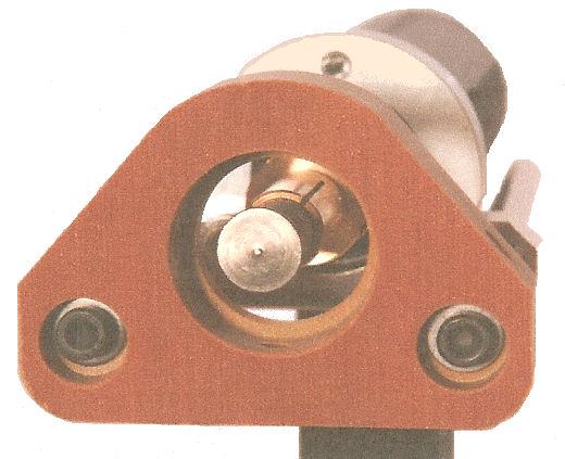
12 SET-UP AND WELDING SELECTING THE PROPER STUD COLLET (STUD HOLDER) The collet is selected to the proper diameter that you are welding. There are three styles of collets; The B collet which is a two piece assembly (collet and insert). The insert determines how much of the stud is engaged in the collet. The CI (Collet Insert) which is a single part and the amount of the stud that is engaged is predetermined. Standard Adjustable Chucks have an adjustable internal screw to manually adjust for the engagement of the stud. The choice between these systems is usually a matter of personal preference. Inserting the selected collet into the stud gun is a simple task. Place the collet into the front holder of the stud gun and set the locking screws to hold it in place. After inserting the collet, mount the two legs and foot piece onto the stud gun. The collet should be centered through the opening of the foot piece. Foot Piece Collet Leg Piece When the legs and foot piece are in place, insert the stud to be welded into the collet. Adjust the leg and foot piece by sliding it into position until approximately 1/8 of the stud protrudes from beyond the foot piece. Lock legs in place with the set screws.

13 SET-UP AND WELDING SELECTING THE SPRING LOAD The proper spring pre load setting on the stud gun will vary depending on the selected application. Generals rules of application would be; mild steel or stainless steel usually in the 1 to 2 range, depending on the stud diameter and the thickness of the base material. Aluminum and other nonferrous metals would require settings from 3 to 5 depending on the diameter of the stud and base material thickness. Adjustment Screw Tension Indicator This spring pre load adjustment is made by turning the screw insert in the back of the stud gun with a screwdriver. On the bottom of the back cap of the stud gun is the indicator numbered 1 thru 5, which will show you the tension setting during the adjustment.
 to the work area, setting up and adjusting the stud gun for the selected stud diameter and material, you can now power on the welder.")
14 SET-UP AND WELDING READY FOR WELDING When you have completed all of the previous steps to prepare for welding, including connecting the stud gun and ground cables to the unit, attaching the ground cable(s) to the work area, setting up and adjusting the stud gun for the selected stud diameter and material, you can now power on the welder. ON/OFF SWITCH FUSE The controller ON/OFF switch is located on the rear of the unit in the upper right hand corner. Below this switch is the 15amp fuse holder for the system.

15 SET-UP AND WELDING VOLTAGE SELECTION Selecting the required weld voltage is achieved by turning the selector knob. The voltage range is from 35VDC to 200VDC. The voltage is determined by the diameter of the stud and the base material. Voltage Adjustment Knob Approximate voltage staring points are listed below. Fine tuning the voltage to meet your requirement for your specific application is recommended. MODEL TWE 250 Diameter Voltage (DC) 14 ga ga # # / MODEL TWE 321 & 375 Diameter Voltage (DC) 14 ga ga # # / / /8 (TWE 375) NOTE***when welding cupped head insulation pins, set the DC Voltage to 35 volts to begin and increase as necessary. Adjust the spring pressure on the CD gun between #1 and #3 as necessary.

,")
16 TESTING WELD SETTINGS TESTING YOUR SETTINGS When you have performed all of the presets as discussed in this manual, it is recommended that you perform several test welds with the same diameter stud and base material that you will be using. This will verify that all of the settings are correct to the results you desire. Welding is done by placing the stud into the collet, and pressing the stud gun to the work piece, compressing the spring. This is why the stud must protrude beyond the foot piece at least 1/8. Holding the gun perpendicular to the work piece, and aligning the stud to the desired position on the work piece, press down so that the foot piece is flush with the work piece (spring compressed), and depress the trigger. When removing the stud gun from the welded stud, always lift the stud gun vertically from the welded stud in order to maintain the proper tension of the collet. Spreading the collet when lifting the stud gun from the welded stud will shorten the life of the collet and will eventually create an undesirable weld.

17 SET-UP AND WELDING INSPECTING THE WELD Visually inspect the weld. A good weld will result in an all around weld, with a small visible amount of weld surrounding the flange of the stud. Too much splatter and the weld is too hot, lower the voltage. No splatter and the weld is too cold, increase the voltage. If you get weld flash to one side of the stud as opposed to an even amount around the base of the flange, this is called arc blow, and can be solved by repositioning the ground clamp or using a dual ground clamp. Proper welded studs can be tested by either torquing or bending the stud. The welded flange of the stud should stay in place using either method, even though the threaded portion of the stud breaks. If the base material is very thin, then a full slug, the diameter of the flange will pull from the base metal for a properly welded stud. CD Stud Welding Steps


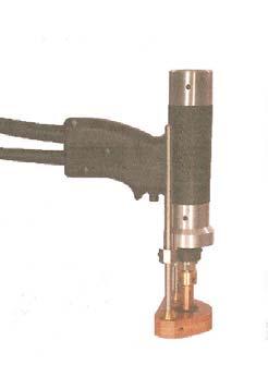
18 SET-UP AND WELDING CD STUD GUN VIEWS
19 CD Parts and Accessories CD STUD GUN EXPLODED VIEW
20 CD Stud Gun Parts List ITEM QUANTITY PART# DESCRIPTION Rear End Cap Spring Pre Load Adjuster Adjustable Spring Seat Cable Bushing Shaft Clip Spring Fixed Spring Seat Weld Cable Boot Control Cable Boot Cable Connector Stud Gun Shaft Stud Gun Body Molding Trigger Switch Trigger Button Trigger Button Sleeve Bellows Retainer Control Cable Connector Shaft Bearing Bellows Front End Cap

21 CD Parts and Accessories CD CONTROLLER VIEW
22 CD Controller Parts List ITEM QUANTITY PART# DESCRIPTION 1 1 TWE01021 Handle 2 1 TWE01031 Cover 3 1 TWE01014 Relay 4 1 TWE01010 TRIAC 5 1 TWE01073 Thyristor Plate 6 2 TWE01030 Cross Over Link 7 1 TWE01028 Negative BUSS 8 1 TWE01002 Thyristor 9 1 TWE01003 Thyrister Clamp 10 3 TWE01011 Flyback Diode 11 2 TWE01004 Main Capacitor 13 1 TWE01027 Link BUSS Bar 17 1 TWE01001 PC Board 18 1 TWE01033 Front Panel 19 1 TWE01026 Front Label 21 1 TWE01017 Control Knob Weld Connector Control Socket 25 4 TWE01018 Rubber Feet 26 1 TWE01055 Serial Number 27 1 TWE01034 Base Plate 28 1 TWE01045 Strain Relief 29 1 TWE Amp Breaker 30 1 TWE01013 Power Switch 31 1 TWE01005 Transformer 33 1 TWE01015 Fan 34 1 TWE01016 Fan Guard 35 1 TWE01008 Main Resistor 36 1 TWE01029 Positive BUSS 37 3 TWE01058 Nylon Standoff 38 1 TWE01009 Rectifier 39 1 TWE01019 Terminal Block 40 2 TWE01040 Resistor Mounts 41 1 TWE01006 Wire Harness
OPERATION MANUAL MODELS TWE-250 TWE-321 TWE-375 TRU WELD EQUIPMENT COMPANY 6400 N. HONEYTOWN ROAD SMITHVILLE, OHIO (330)
") OPERATION MANUAL MODELS TWE-250 TWE-321 TWE-375 TRU WELD EQUIPMENT COMPANY 6400 N. HONEYTOWN ROAD SMITHVILLE, OHIO 44677 (330) 669 2773 Version 1.3 Date 10/20/2010 TRU WELD EQUIPMENT LIMITED WARRANTY All
OPERATION MANUAL MODELS TWE-250 TWE-321 TWE-375 TRU WELD EQUIPMENT COMPANY 6400 N. HONEYTOWN ROAD SMITHVILLE, OHIO 44677 (330) 669 2773 Version 1.3 Date 10/20/2010 TRU WELD EQUIPMENT LIMITED WARRANTY All
OPERATION MANUAL TWE-375 CAPACITOR DISCHARGE WELDER
 OPERATION MANUAL TWE-375 CAPACITOR DISCHARGE WELDER TRU WELD EQUIPMENT COMPANY 6400 N. HONEYTOWN ROAD SMITHVILLE, OHIO 44677 (330) 725 7744 TWE@tfpcorp.com Version 1.0 Date 8/13/2013 TRU WELD EQUIPMENT
OPERATION MANUAL. TWE Pin Welder. Model TWP-2 TRU WELD EQUIPMENT COMPANY 6400 N. HONEYTOWN ROAD SMITHVILLE, OHIO (330) Revision 2.
 Revision 2.") OPERATION MANUAL TWE Pin Welder Model TWP-2 TRU WELD EQUIPMENT COMPANY 6400 N. HONEYTOWN ROAD SMITHVILLE, OHIO 44677 (330) 725 7744 Revision 2.0 8/22/2013 TRU WELD EQUIPMENT LIMITED WARRANTY All goods
OPERATION MANUAL TWE Pin Welder Model TWP-2 TRU WELD EQUIPMENT COMPANY 6400 N. HONEYTOWN ROAD SMITHVILLE, OHIO 44677 (330) 725 7744 Revision 2.0 8/22/2013 TRU WELD EQUIPMENT LIMITED WARRANTY All goods
OPERATION MANUAL. Model TWP-2. Toll free customer support:
 OPERATION MANUAL TWE StudPro Pin Welder Lite Model TWP-2 Downey, CA 9459 Washburn Rd. Downey, CA 90242 Phone- 800.252.1919 Fax- 562.862.3022 Hayward, CA Phoenix, AZ 2391 American TRU WELD Ave. EQUIPMENT
OPERATOR S MANUAL. TW-i SERIES. Capacitor Discharge Stud Welder. MODELS: TW-i 250 TW-i 250CP TW-i 321 TW-i 375
 OPERATOR S MANUAL TW-i SERIES Capacitor Discharge Stud Welder MODELS: TW-i 250 TW-i 250CP TW-i 321 TW-i 375 TRU-WELD EQUIPMENT COMPANY www.truweldstudwelding.com (330) 725-7744 CONTENTS Description Pages
OPERATOR S MANUAL ACE - P100
 OPERATOR S MANUAL ACE - P100 Pin Welder TRU-WELD EQUIPMENT COMPANY www.truweldstudwelding.com (330) 725-7744 CONTENTS Description Pages Warranty Information 1 Safety 2 Specifications and Features 3 Product
OPERATOR S MANUAL StudPro LiteXI Pin Welder Stud Welding Products, Inc
 OPERATOR S MANUAL StudPro LiteXI Pin Welder CONTENTS Description Pages Safety 2 Specifications and Features 3 Product Components 4-5 Screen Operation 6-8 Setup and Welding 9-11 CD Gun Exploded View 12
OPERATOR S MANUAL STUDPRO SERIES
 OPERATOR S MANUAL STUDPRO SERIES Capacitor Discharge Stud Welder MODELS: StudPro 2500XI StudPro 2500XIP StudPro 3125XI StudPro 3750XI CONTENTS Description Pages Safety 2 Specifications and Features 3 Product
POWER PINNER CD HAND WELDER 7300 OPERATOR S MANUAL
 POWER PINNER CD HAND WELDER 7300 OPERATOR S MANUAL Copyright: April 7, 2014 Gripnail Corporation Revised: January 25, 2018 An Employee Owned Company 97 Dexter Road East Providence, Rhode Island 02914-2045
OPERATION MANUAL MODELS TWE-321 TWE-375. Toll free customer support:
 OPERATION MANUAL MODELS StudPro TWE-250 2500i TWE-321 TWE-375 Downey, CA 9459 Washburn Rd. Downey, CA 90242 Phone- 800.252.1919 Fax- 562.862.3022 Hayward, CA Phoenix, AZ 2391 American TRU WELD Ave. EQUIPMENT
Cutlass Fasteners, Inc. 83 Vermont Ave., Unit 6, Warwick, RI Tel: (401) Fax: (401) cutlass-studwelding.com
 Fax: (401) cutlass-studwelding.com") MODEL : BANTAM C8 PART NO. : 602-325P SERIAL NO. : PLEASE READ THIS OPERATION AND MAINTENANCE MANUAL CAREFULLY BEFORE USING YOUR NEW CUTLASS STUD WELDER. COPYRIGHT CFI 2009 email: sales@ PAGE - 1 - WARRANTY
MODEL : BANTAM C8 PART NO. : 602-325P SERIAL NO. : PLEASE READ THIS OPERATION AND MAINTENANCE MANUAL CAREFULLY BEFORE USING YOUR NEW CUTLASS STUD WELDER. COPYRIGHT CFI 2009 email: sales@ PAGE - 1 - WARRANTY
Cutlass Fasteners, Inc. 83 Vermont Ave., Unit 6, Warwick, RI Tel: (401) Fax: (401) cutlass-studwelding.com
 Fax: (401) cutlass-studwelding.com") MODEL : BANTAM C8 BANTAM C10 PART NO. : 602-325A 602-343A SERIAL NO. : PLEASE READ THIS OPERATION AND MAINTENANCE MANUAL CAREFULLY BEFORE USING YOUR NEW CUTLASS STUD WELDER. COPYRIGHT CFI 2009 email: sales@
MODEL : BANTAM C8 BANTAM C10 PART NO. : 602-325A 602-343A SERIAL NO. : PLEASE READ THIS OPERATION AND MAINTENANCE MANUAL CAREFULLY BEFORE USING YOUR NEW CUTLASS STUD WELDER. COPYRIGHT CFI 2009 email: sales@
ARC 1850 LIST OF FIGURES
 PAGE 1.0 INTRODUCTION... 1 2.0 WARRANTY... 1 3.0 UNPACKING YOUR UNIT... 1 4.0 SUGGESTED SAFETY PRECAUTIONS...... 1 4.1 PERSONAL SAFETY PRECAUTIONS. 1 4.2 POWER SUPPLY SAFETY PRECAUTIONS.. 2 5.0 GENERAL
Cutlass Fasteners, Inc. 83 Vermont Ave., Unit 6, Warwick, RI Tel: (401) Fax: (401) cutlass-studwelding.com
 Fax: (401) cutlass-studwelding.com") MODEL : PHM-10 SHORT CYCLE WELD GUN PART NO. : PHM-10 SERIAL NO. : PLEASE READ THIS OPERATION AND MAINTENANCE MANUAL CAREFULLY BEFORE USING YOUR NEW CUTLASS STUD WELDER. COPYRIGHT CFI 2009 email: sales@
MODEL : PHM-10 SHORT CYCLE WELD GUN PART NO. : PHM-10 SERIAL NO. : PLEASE READ THIS OPERATION AND MAINTENANCE MANUAL CAREFULLY BEFORE USING YOUR NEW CUTLASS STUD WELDER. COPYRIGHT CFI 2009 email: sales@
OPERATION INSTRUCTIONS
 www.r-techwelding.co.uk Email: sales@r-techwelding.co.uk Tel: 01452 733933 Fax: 01452 733939 ProArc 175 INVERTER ARC WELDER OPERATION INSTRUCTIONS Version 2017-10 2 3 Thank you for selecting the R-Tech
OPERATION/ MAINTENANCE MANUAL
 208 VERSION OPERATION/ MAINTENANCE MANUAL TABLE OF CONTENTS Section 1 SAFETY PRECAUTIONS PAGE 1.0 INTRODUCTION... 1 2.0 WARRANTY... 1 3.0 UNPACKING YOUR UNIT... 1 4.0 SUGGESTED SAFETY PRECAUTIONS... 1
OPERATION/ MAINTENANCE MANUAL
 OPERATION/ MAINTENANCE MANUAL TABLE OF CONTENTS Section 1 SAFETY PRECAUTIONS PAGE 1.0 INTRODUCTION... 1 2.0 WARRANTY... 1 3.0 UNPACKING YOUR UNIT... 1 4.0 SUGGESTED SAFETY PRECAUTIONS... 1 4.1 PERSONAL
MODEL ELC-12/40-CVM-D BATTERY CHARGER
 NATIONAL RAILWAY SUPPLY MODEL ELC-12/40-CVM-D BATTERY CHARGER Installing, Operating and Service Instructions for the ELC-12/40-CVM-D Solid State Charger PLEASE SAVE THESE IMPORTANT SAFETY AND OPERATING
OPERATION/ MAINTENANCE MANUAL
 OPERATION/ MAINTENANCE MANUAL TABLE OF CONTENTS PAGE 1.0 INTRODUCTION... 1 2.0 WARRANTY... 1 3.0 UNPACKING YOUR UNIT... 1 4.0 SUGGESTED SAFETY PRECAUTIONS...... 1 4.1 PERSONAL SAFETY PRECAUTIONS. 1 4.2
MODEL ELC-12/60-D BATTERY CHARGER
 *32198* NATIONAL RAILWAY SUPPLY Installing, Operating and Service Instructions for the 12/60 Solid State Charger MODEL ELC-12/60-D BATTERY CHARGER PLEASE SAVE THESE IMPORTANT SAFETY AND OPERATING INSTRUCTIONS
TABLE OF CONTENTS LIST OF FIGURES
 TABLE OF CONTENTS Section 1 SAFETY PRECAUTIONS PAGE 1.0 INTRODUCTION... 1 2.0 WARRANTY... 1 3.0 UNPACKING YOUR UNIT... 1 4.0 SUGGESTED SAFETY PRECAUTIONS... 1 4.1 PERSONAL SAFETY PRECAUTIONS 1 4.2 POWER
Installation Instructions for Remote Mount HMI 211 Display Panel Kit A045J206
 Instruction Sheet 7-2013 Installation Instructions for Remote Mount HMI 211 Display Panel Kit A045J206 1 Introduction The information contained within is based on information available at the time of going
LESTRONIC II BATTERY CHARGER MODEL 07210
 LESTRONIC II BATTERY CHARGER MODEL 07210 PLEASE SAVE THESE IMPORTANT SAFETY AND OPERATING INSTRUCTIONS For correct operation of the equipment, it is important to read and be familiar with this entire manual
AUTO CHARGE 4000 MODEL #: AUTOMATIC DUAL OUTPUT BATTERY CHARGER INSTRUCTION MANUAL. Ph: Fax:
 INSTRUCTION MANUAL AUTO CHARGE 4000 AUTOMATIC DUAL OUTPUT BATTERY CHARGER MODEL #: 091-89-12 INPUT: 120 Volt, 50/60 Hz, 8 Amps OUTPUT BATTERY CHARGER: 40 Amps OUTPUT BATTERY SAVER: 5 Amps File: IM_091-89-12_reve.indd
AUTO CHARGE D PUMP PLUS
 INSTRUCTION MANUAL AUTO CHARGE D PUMP PLUS AUTOMATIC DUAL OUTPUT BATTERY CHARGER Designed Specifically for Vehicles with DDEC ENGINES MODEL #: 091-9-DPP INPUT: 120 Volt, 60 Hz, 8 Amps OUTPUT VEHICLE BATTERY:
MMA 160S ARC/MMA WELDER OPERATION INSTRUCTIONS
 www.r-techwelding.co.uk MMA 160S ARC/MMA WELDER OPERATION INSTRUCTIONS 2 Thank you for selecting the R-Tech MMA160S Inverter Arc Welder. The MMA160S has many benefits over traditional Arc welders, including
TWE - SC1600. Operations Manual
 TWE - SC1600 Stud Welding System Operations Manual The SC1600 is a fully integrated stud welding system with two digital controls for time and current. The system was designed to be a perfect fit for shop
AUTO CHARGE D2 MODEL #: AUTOMATIC TRIPLE OUTPUT BATTERY CHARGER INSTRUCTION MANUAL
 INSTRUCTION MANUAL AUTO CHARGE D2 AUTOMATIC TRIPLE OUTPUT BATTERY CHARGER Designed Specifically for Vehicles with DDEC ENGINES MODEL #: 091-74-12 INPUT: 120 Volt, 60 Hz, 8 Amps OUTPUT VEHICLE BATTERY 1
AUTO CHARGE 4000 MODEL #: LOW PROFILE CHARGER AUTOMATIC DUAL OUTPUT BATTERY CHARGER INSTRUCTION MANUAL
 INSTRUCTION MANUAL AUTO CHARGE 4000 LOW PROFILE CHARGER AUTOMATIC DUAL OUTPUT BATTERY CHARGER Unit supplied with this display MODEL #: 091-89-12 INPUT: 120 Volt, 50/60 Hz, 5 Amps OUTPUT: 45 Amps File:
MODEL 7100 PORTABLE PIN WELDER OPERATOR S MANUAL
 Model 7100 Portable Pin Welder MODEL 7100 PORTABLE PIN WELDER OPERATOR S MANUAL Copyright: March 22, 2005 Revised: December 20, 2016 Gripnail Corporation An Employee Owned Company 97 Dexter Road East Providence,
INSTRUCTION MANUAL FOR PLASMA CUTTER
 INSTRUCTION MANUAL FOR PLASMA CUTTER IMPORTANT: BEFORE STARTING THE EQUIP- MENT, READ THE CONTENTS OF THIS MANUAL, WHICH MUST BE STORED IN A PLACE FAMILIAR TO ALL USERS FOR THE ENTIRE OPERATIVE LIFE-SPAN
MASTERsine Inverter PXA Series Installation Guide
 Backup Power System Expert TM MASTERsine Inverter PXA Series Installation Guide Important Safety Instructions IMPORTANT: Read and save this Installation Guide for future reference. This chapter contains
OPERATION/ MAINTENANCE MANUAL
 OPERATION/ MAINTENANCE MANUAL TABLE OF CONTENTS 1.0 INTRODUCTION 1 2.0 WARRANTY 1 3.0 UNPACKING YOUR UNIT 1 4.0 SUGGESTED SAFETY PRECAUTIONS 1 5.0 GENERAL DESCRIPTION 2 6.0 THE CD ING PROCESS 2 7.0 POWER
Model: OBD-L On-Board-Diagnostics II Memory Saver Detector
 Model: OBD-L On-Board-Diagnostics II Memory Saver Detector OWNERS MANUAL IMPORTANT SAFETY INSTRUCTIONS SAVE THESE INSTRUCTIONS This manual will show you how to use your memory saver detector safely and
RediCoat by Nordson. Hopper and VBF Dolly Systems. Customer Product Manual Part A Issued 10/07
 RediCoat by Nordson Hopper and VBF Dolly Systems Customer Product Manual Part 1082648A Issued 10/07 This document is subject to change without notice. Nordson Corporation Amherst, Ohio USA 2 Table of Contents
Installation Instructions for Load Management Kit A051C329
 Instruction Sheet 12-2014 Installation Instructions for Load Management Kit A051C329 1 Introduction The information contained within is based on information available at the time of going to print. In
AUTO CHARGE DUAL MODEL #: AUTOMATIC DUAL OUTPUT BATTERY CHARGER INSTRUCTION MANUAL. Ph: Fax:
 INSTRUCTION MANUAL AUTO CHARGE DUAL AUTOMATIC DUAL OUTPUT BATTERY CHARGER MODEL #: 091-145-12 INPUT: 120 Volt, 50/60 Hz, 3.5 Amps OUTPUT BAT 1: 10 Amps OUTPUT BAT 2: 10 Amps File: IM_091-145-12_revb.indd
POWER PINNER HAND WELDER 7200 OPERATOR S MANUAL
 POWER PINNER HAND WELDER 7200 OPERATOR S MANUAL Copyright: January 5, 2009 Revised: November 24, 2014 Serial No. 0901189 - Gripnail Corporation An Employee Owned Company 97 Dexter Road East Providence,
MODEL 6010A 6 12 VOLT BATTERY CHARGER ASSOCIATE
 MODEL 600A 6 VOLT BATTERY CHARGER ASSOCIATE IMPORTANT SAFETY INSTRUCTIONS. SAVE THESE INSTRUCTIONS. This manual contains important safety and operating instructions for the battery charger you have purchased.
SOS SERIES SOS1 SOS2. Spares On Site Battery Cabinet Installation Guide rEV3
 Atlantic Battery Systems 1065 Market Street Paterson, NJ 07513 Phone: (800) 875-0073 Fax: (973) 523-2344 sales@atbatsys.com www.atbatsys.com SOS1 SOS2 SOS SERIES Spares On Site Battery Cabinet Installation
LPC 20 MODEL #: LOW PROFILE CHARGER AUTOMATIC SINGLE OUTPUT BATTERY CHARGER INSTRUCTION MANUAL
 INSTRUCTION MANUAL LPC 20 LOW PROFILE CHARGER AUTOMATIC SINGLE OUTPUT BATTERY CHARGER Unit supplied with one of these displays MODEL #: 091-207-12 INPUT: 120 Volt, 50/60 Hz, 7 Amps OUTPUT: 20 Amps File:
TAYLOR STUDWELDING SYSTEMS LIMITED.
 TAYLOR STUDWELDING SYSTEMS LIMITED. OPERATING GUIDE FOR CD MULTIGUN COMPACT CAPACITOR DISCHARGE STUDWELDING EQUIPMENT A TAYLORMADE CAPACITOR DISCHARGE PRODUCT INDEX PAGE CONTENT 3 GENERAL INFORMATION 5
IMPORTANT SAFETY INSTRUCTIONS
 1163714 1.5 AMP 12VOLT TRICKLE 1.5 AUTOMATIC AMP AUTOMATIC TRICKLE 1.5 AMP AUTOMATIC 12V12VOLT BATTERY CHARGER IMPORTANT SAFETY INSTRUCTIONS 1. SAVE THESE INSTRUCTIONS This product offers a wide range
Cutlass Fasteners, Inc. 83 Vermont Ave., Unit 6, Warwick, RI Tel: (401) Fax: (401) cutlass-studwelding.com
 Fax: (401) cutlass-studwelding.com") MODEL : PINTO YTEM/PKM-1B GUN PART NO. : C-1K ERIAL NO. : PLEAE READ THI OPERATION AND MAINTENANCE MANUAL CAREFULLY BEFORE UING YOUR NEW CUTLA TUD WELDER. COPYRIGHT CFI 2009 email: sales@ PAGE - 1 - WARRANTY
MODEL : PINTO YTEM/PKM-1B GUN PART NO. : C-1K ERIAL NO. : PLEAE READ THI OPERATION AND MAINTENANCE MANUAL CAREFULLY BEFORE UING YOUR NEW CUTLA TUD WELDER. COPYRIGHT CFI 2009 email: sales@ PAGE - 1 - WARRANTY
Hand Held Capacitor Discharge Welding System. Owner s Manual
 Hand Held Capacitor Discharge Welding System Owner s Manual SureShot II CD Stud Welding System Owner s Manual Installation Operation Maintenance MIDWEST FASTENERS, INC. 450 Richard Street Miamisburg, OH
LESTRONIC II BATTERY CHARGER MODEL 19740
 *01679* LESTRONIC II BATTERY CHARGER MODEL 19740 PLEASE SAVE THESE IMPORTANT SAFETY AND OPERATING INSTRUCTIONS For correct operation of the equipment, it is important to read and be familiar with this
ALU-29CF Portable Light NSN:
 ALU-29CF Portable Light NSN: 6520-01-446-4170 COMMAND l AIR OPERATION / MAINTENANCE MANUAL & PARTS LIST TABLE OF CONTENTS Introduction................................................................3 Purpose.............................................................3
Installation Instructions
 patent pending Portable Proportional Braking System Installation Instructions Part number 9400 Towing and Suspension Solutions ROADMASTER, Inc. 6110 NE 127th Ave. Vancouver, WA 98682 800-669-9690 Fax 360-735-9300
LESTRONIC II BATTERY CHARGER TAYLOR-DUNN MODEL TYPE 24LC25-8ET
 LESTRONIC II BATTERY CHARGER TAYLOR-DUNN 79-301-10 MODEL 13110-32 TYPE 24LC25-8ET AC Supply: DC Output: Battery Capacity: Specifications 120 volts, 60 Hertz, single-phase 24 volts, 32 amps Use only on
OPERATION/ MAINTENANCE MANUAL
 OPERATION/ MAINTENANCE MANUAL TABLE OF CONTENTS 1.0 INTRODUCTION 1 2.0 WARRANTY 1 3.0 UNPACKING YOUR UNIT 1 4.0 SUGGESTED SAFETY PRECAUTIONS 1 5.0 GENERAL DESCRIPTION 2 6.0 THE CD ING PROCESS 2 7.0 POWER
TWE Operations Manual
 HEAVY-DUTY STUD GUN Operations Manual The TWE17000 has been designed to fit comfortably for all hands, including when wearing a work glove. The neck of the handle has been tapered so that when grasped,
BATTERY SAVER LOW RIPPLE HO
 INSTRUCTION MANUAL BATTERY SAVER LOW RIPPLE HO LOW RIPPLE POWER SUPPLY / AUTOMATIC LOAD SWITCH FOR 12VDC VEHICLE SYSTEMS MODEL #: 091-195-12 INPUT: 120 Volt, 50/60 Hz, 4.5 Amps RMS OUTPUT: 13.2 Volts DC,
BL7000 SYSTEM OPERATING MANUAL
 BL7000 SYSTEM OPERATING MANUAL REV 2.0 208 / 230V COPYRIGHT 1995 Xenotech, Inc. PAGE 1 POWER INPUT CONNECTOR WIRING INSTRUCTIONS THE INPUT POWER REQUIREMENTS FOR A 7 KW POWER SUPPLY ARE AS FOLLOWS. VOLTAGE
PS MIG Volt MIG Welder Assembly & Operating Instructions
 PS07570 201205 MIG135 115 Volt MIG Welder Assembly & Operating Instructions READ ALL INSTRUCTIONS AND WARNINGS BEFORE USING THIS PRODUCT. This manual provides important information on proper operation
TAYLOR STUDWELDING SYSTEMS LIMITED. OPERATING MANUAL FOR CD-M RANGE - SERIES 2 COMPACT CAPACITOR DISCHARGE STUDWELDING EQUIPMENT MODELS M8, M9 & M10
 TAYLOR STUDWELDING SYSTEMS LIMITED. OPERATING MANUAL FOR CD-M RANGE - SERIES 2 COMPACT CAPACITOR DISCHARGE STUDWELDING EQUIPMENT MODELS M8, M9 & M10 INDEX PAGE CONTENT 1 GENERAL INFORMATION 3 INTRODUCTION
DELTA O-RING CARTRIDGE SEAL ASSEMBLY AND INSTALLATION INSTRUCTIONS INTRODUCTION:
 DELTA O-RING CARTRIDGE SEAL ASSEMBLY AND INSTALLATION INSTRUCTIONS INTRODUCTION: These instructions are provided to familiarize the user with the seal and its use. The instructions must be read carefully
WELDING POSITIONER OPERATION MANUAL MODEL TT-100 V1.0
 WELDING POSITIONER OPERATION MANUAL MODEL TT-100 Carefully read and understand these operation instructions before operating, inspecting, or servicing this product. This manual for use with Serial Numbers
Deltran Battery Tender 6V/12V 4Amp 5 & 10 Bank Battery Management System TABLE 1. Length of Cord, Feet AWG Size of Cord
 Deltran Battery Tender 6V/12V 4Amp 5 & 10 Bank Battery Management System Designed for Six-cell and three-cell Flooded/AGM/GEL Lead-Acid Batteries and Four-Cell Lithium Iron Phosphate (LiFePO4) Batteries
AUTO CHARGE 12 HO MODEL #: MODEL #: MODEL #: AUTOMATIC SINGLE OUTPUT BATTERY CHARGER INSTRUCTION MANUAL
 INSTRUCTION MANUAL AUTO CHARGE 12 HO AUTOMATIC SINGLE OUTPUT BATTERY CHARGER MODEL #: 091-170-6 MODEL #: 091-170-12 MODEL #: 091-170-24 File: IM_091-170-xx_revd.indd Rev: D Revised By: MFG Date: 10-23-2013
HOT WASHER MODEL NO: KING 125 OPERATION & MAINTENANCE INSTRUCTIONS PART NO: LS1009
 HOT WASHER MODEL NO: KING 125 PART NO: 7320170 OPERATION & MAINTENANCE INSTRUCTIONS LS1009 INTRODUCTION Thank you for purchasing this Hot Washer. This machine is a portable, high pressure power washer,
OPERATION AND MAINTENANCE MANUAL
 WREN IBT SERIES HYDRAULIC TORQUE WRENCHES IBT SQUARE DRIVE SERIES OPERATION AND MAINTENANCE MANUAL FOR WREN Products: POINT 75, 1IBT, 3IBT, 5IBT, 8IBT, 10IBT, 20IBT, 25IBT, 35IBT, 50IBT SQUARE DRIVE HYDRAULIC
SP6. Automatic Battery Charger. Model
 Model SP6 Automatic Battery Charger OWNERS MANUAL PLEASE SAVE THIS OWNERS MANUAL AND READ BEFORE EACH USE. This manual will explain how to use the charger safely and effectively. Please read and follow
Installation Instructions for Aux 101 Kit A044Z055
 Instruction Sheet 7-2013 Installation Instructions for Aux 101 Kit A044Z055 1 Introduction The information contained within is based on information available at the time of going to print. In line with
DRAWING NUMBER: GK-191-P-200-2C
 PARTS BREAK DOWN FOR A RIGID KAT LOWER HOUSING ASSEMBLY DRAWING NUMBER: GK-9-P-200-2C GK-7-005 KAT LOWER HOUSING 2 GK-7-02 WHEEL ADJUSTMENT SCREW 3 GK-0-062 3/4-6UNC HEX HEAD JAM NUT 4 GK-7-02 WHEEL ADJUSTMENT
AIR FILTER MODEL NO: AF1000 OPERATION & MAINTENANCE INSTRUCTIONS PART NO:
 AIR FILTER MODEL NO: AF1000 PART NO: 6471160 OPERATION & MAINTENANCE INSTRUCTIONS 1208 INTRODUCTION Thank you for purchasing this Clarke Air Filter. Before you try to use this product, read this manual
DELTA O-RING CARTRIDGE SEAL ASSEMBLY AND INSTALLATION INSTRUCTIONS INTRODUCTION:
 DELTA O-RING CARTRIDGE SEAL ASSEMBLY AND INSTALLATION INSTRUCTIONS INTRODUCTION: These instructions are provided to familiarize the user with the seal and its use. The instructions must be read carefully
MODEL 6017 OPERATOR'S MANUAL
 MODEL 6017 OPERATOR'S MANUAL ASSOCIATE D IMPORTANT SAFETY INSTRUCTIONS 1. SAVE THESE INSTRUCTIONS. This manual contains important safety and operating instructions for the battery charger you have purchased.
POWER SUPPLY MODEL XP-800. TWO AC VARIABLE VOLTAGES; 0-120V and 7A, PLUS UP TO 10A. Instruction Manual. Elenco Electronics, Inc.
 POWER SUPPLY MODEL XP-800 TWO AC VARIABLE VOLTAGES; 0-120V and 0-40V @ 7A, PLUS 0-28VDC @ UP TO 10A Instruction Manual Elenco Electronics, Inc. Copyright 1991 Elenco Electronics, Inc. Revised 2002 REV-I
Installation Instructions
 Portable Proportional Braking System Installation Instructions Part number 9400 Time Tested Time Proven ROADMASTER, Inc. 6110 NE 127th Ave. Vancouver, WA 98682 800-669-9690 Fax 360-735-9300 roadmasterinc.com
Model: SE-4020-CA Automatic Battery Charger
 OWNERS MANUAL Model: SE-4020-CA Automatic Battery Charger PLEASE SAVE THIS OWNERS MANUAL AND READ BEFORE EACH USE. This manual will explain how to use the battery charger safely and effectively. Please
STUD WELDING EQUIPMENT & ACCESSORIES CATALOG
 STUD WELDING EQUIPMENT & ACCESSORIES CATALOG WWW.PROWELDINTERNATIONAL.COM 129 COMMERCE DR LAGRANGE, OH. 44050 PHONE: (440)-355-6064 FAX: (440)-355-6474 07/01/02 CD WELDING SYSTEMS PART # LIST PRICE CD-212
PUMP PLUS 2000 PLC MODEL #: PP AUTOMATIC DUAL OUTPUT BATTERY CHARGER INSTRUCTION MANUAL
 INSTRUCTION MANUAL PUMP PLUS 2000 PLC AUTOMATIC DUAL OUTPUT BATTERY CHARGER Supplied with Dual Bar Graph Display MODEL #: 091-237-12-PP INPUT: 120 Volt, 60 Hz, 3.5 Amps OUTPUT BATTERY 1 and 2: 15 or 18
Sentry Battery Charger. Installation and Operations Manual Section 75
 Sentry Battery Charger Installation and Operations Manual 00-02-0616 03-03-08 Section 75 In order to consistently bring you the highest quality, full featured products, we reserve the right to change our
Operations and Service Manual. X30208 Load Bank
 Operations and Service Manual Read all instructions before using the load bank Contents 1. Components... 3 Total Assembly... 3 2) Specifications... 4 a)... 4 3) Receiving... 5 4) Safety... 5 a) Ground
Reproduction or other use of this Manual, without the express written consent of Vulcan, is prohibited.
 SERVICE MANUAL ELECTRIC BRAISING PANS (30 & 40 GALLON) VE30 VE40 ML-126849 ML-126850 VE40 SHOWN - NOTICE - This Manual is prepared for the use of trained Vulcan Service Technicians and should not be used
LESTRONIC II BATTERY CHARGER BUILT-IN OR PORTABLE CHARGERS
 LESTRONIC II BATTERY CHARGER BUILT-IN OR PORTABLE CHARGERS PLEASE SAVE THESE IMPORTANT SAFETY AND OPERATING INSTRUCTIONS For correct operation of the equipment, it is important to read and be familiar
MPPC40DVI OWNER S MANUAL
 MPPC40DVI OWNER S MANUAL 4/2017 WARNING: Read carefully and understand all ASSEMBLY AND OPERATION INSTRUCTIONS before operating. Failure to follow the safety rules and other basic safety precautions may
Self-Testing Industrial Series
 Series: AS-I (Maint.-Free) Self-Testing Industrial Series Emergency Lighting Equipment Instructions for INSTALLATION OPERATION SERVICE SPECIFICATIONS 1300650 1300654 1300666 1300754 1300823 1300886 Hubbell
BATTERY STARTER/CHARGER MODEL NO: BC125, BC190
 BATTERY STARTER/CHARGER MODEL NO: BC125, BC190 PART NO: 6210125, 6210200 OPERATION & MAINTENANCE INSTRUCTIONS LS0616 INTRODUCTION Thank you for purchasing this CLARKE Battery starter / charger Please read
OPERATOR'S MANUAL IMPORTANT SAFETY INSTRUCTIONS
 ASSOCIATED OPERATOR'S MANUAL IMPORTANT SAFETY INSTRUCTIONS MODEL 6366 12 VOLT, 0-20 AMP 4 X 20 BATTERY CHARGER 1. SAVE THESE INSTRUCTIONS. This manual contains important safety and operating instructions
PC40 INVERTER PLASMA CUTTER 230V 40A SUM OWNER S MANUAL
 PC40 INVERTER PLASMA CUTTER 230V 40A SUM-900990 OWNER S MANUAL WARNING: Read carefully and understand all ASSEMBLY AND OPERATION INSTRUCTIONS before operating. Failure to follow the safety rules and other
Stick/Mig Capability Welding Excellence Modular Construction Environment Protected 2,000 Watt AC Power for Tools
 E300 3+2 Electric Welder Service Manual Stick/Mig Capability Welding Excellence Modular Construction Environment Protected 2,000 Watt AC Power for Tools SVM_E300 3+2 SAFETY Arc Welding Safety Precautions
HD 7700 Setup & Operator Manual
 HD 7700 Setup & Operator Manual Issue 1 December, 01 Performance Design Inc. The Heavy Duty Ultima (HD 7700) electric punch has been designed to punch most any job that may pass through your bindery or
OPERATION INSTRUCTIONS
 www.r-techwelding.co.uk Tel: 01452 733933 Fax 01452 733939 PLASMA 50HF INVERTER PLASMA CUTTER OPERATION INSTRUCTIONS Version 2014-1 2 Thank you for selecting the R-Tech PLASMA 50HF Inverter Plasma Cutter
X100P Load Bank. Read all instructions before using the load bank. Contents
 X100P Load Bank Read all instructions before using the load bank Contents 1. Components... 3 Total Assembly... 3 2) Specifications... 4 a) X100P Load Bank... 4 3) Receiving... 4 4) Safety... 5 a) Grounding...
CAUTION. Even Brakes with a black cable need second vehicle kit Even Brakes with a blue cable need second vehicle kit 98450
 cable not included cable not included Even Brakes with a blue cable need second vehicle kit 98450 Even Brakes with a black cable need second vehicle kit 98400 Check the Even Brake serial number before
MMW220PC OWNER S MANUAL
 MMW220PC OWNER S MANUAL 12/2015 WARNING: Read carefully and understand all ASSEMBLY AND OPERATION INSTRUCTIONS before operating. Failure to follow the safety rules and other basic safety precautions may
EASY CHARGE Waterproof portable Battery Charger
 EASY CHARGE Waterproof portable Battery Charger 1.1 AND 4.3 AMP MODELS EN NL, DE, FR, ES, IT USER S MANUAL WWW.MASTERVOLT.COM/EASYCHARGE-PORTABLE 10000009117/04 2 EN / EasyCharge 1.1 and 4.3 Amp - User
Loose Parts Note: Determine the left and right sides of the machine from the normal operating position.
 Brake Kit Dingo TX 0 & Compact Utility Loader Part No. 0 0 & 0 Loose Parts Note: Determine the left and right sides of the machine from the normal operating position. Description Qty. Use Drive wheel Brake
ACCUSENSE CHARGE SERIES ON/OFF BOARD FULLY AUTOMATIC BATTERY CHARGER
 ACCUSENSE CHARGE SERIES ON/OFF BOARD FULLY AUTOMATIC BATTERY CHARGER SPECIFICATIONS: *Photo for reference only* Part number 8890439 Mode Select: Selects Battery Type Refer to Section 6. IMPORTANT: READ
Operations and Service Manual. XE400D-SB Load Bank
 Operations and Service Manual XE400D-SB Load Bank Read all instructions before using the load bank Contents 1. Components... 3 Total Assembly... 3 2) Specifications... 4 a) XE400D-SB Load Bank... 4 3)
OPERATING INSTRUCTIONS
 www.r-techwelding.co.uk email: sales@r-techwelding.co.uk Tel: 01452 733933 Fax 01452 733939 IMIG 180 PORTABLE INVERTER MIG/MAG/MMA WELDER OPERATING INSTRUCTIONS Version 2017-1 Thank you for selecting
CFT24 &CFT230 PART NOS:
 FUEL TRANSFER PUMP Model Nos. CFT12, CFT24 &CFT230 PART NOS: 7160010, 7160020 & 7160030 INSTALLATION & OPERATING INSTRUCTIONS ORIGINAL INSTRUCTIONS GC05/18 REV 5 INTRODUCTION Thank you for purchasing this
MPPC60I OWNER S MANUAL
 MPPC60I OWNER S MANUAL 4/2017 WARNING: Read carefully and understand all ASSEMBLY AND OPERATION INSTRUCTIONS before operating. Failure to follow the safety rules and other basic safety precautions may
XENON POWER SUPPLY 4000 Watt Gladiator IV
 XENON POWER SUPPLY 4000 Watt Gladiator IV 220 Volt Equipment Type 62-00049 Rev. February 2003 STRONG INTERNATIONAL a division of Ballantyne of Omaha, Inc. 4350 McKinley Street Omaha, Nebraska 68112 USA
MODEL A96 SERIES. 130Vdc Switchmode Utility Rectifier / Battery Charger. Used with LaMarche Power Cage ECN/DATE
 MODEL A96 SERIES 130Vdc Switchmode Utility Rectifier / Battery Charger Used with LaMarche Power Cage CPN112138 ECN/DATE ISSUE DATE: ECN 17010-12/05 106 BRADROCK DRIVE DES PLAINES, IL. 60018-1967 (847)
PARTS BREAKDOWN FOR HIGH AND LOW SPEED GEAR ASSEMBLIES
 PARTS BREAKDOWN FOR HIGH AND LOW SPEED GEAR ASSEMBLIES Refer to sketches on previous page. ITEM PART NUMBER DESCRIPTION QTY 120 GK-166-169 LOW SPEED GEAR TRAIN ASSEMBLY (ITEMS 121 TO 127) 121 GK-166-171
MB V 3-IN-1 JUMP STARTER WITH SPIRAL WOUND BATTERY
 MB3730 12V 3-IN-1 JUMP STARTER WITH SPIRAL WOUND BATTERY 1 IMPORTANT SAFETY INSTRUCTIONS 1. SAVE THESE INSTRUCTIONS - This manual contains important safety and operating instructions for this PowerStation.
Replacing the Battery in the Patriot SPS 250, SPS 300 and SPS 450
 Replacing the Battery in the Patriot SPS 250, SPS 300 and SPS 450 PAT 609 P February 1, 1993 This PAT describes how to replace the battery in Patriot SPS 250, SPS 300, and SPS 450 units. Replacing the
Abbeon Cal, Inc. Model BD-50E HIGH FREQUENCY GENERATOR OPERATING MANUAL
 Abbeon Cal, Inc. Model BD-50E HIGH FREQUENCY GENERATOR OPERATING MANUAL DESCRIPTION. The Model BD-50E is a rugged tester designed for testing tank lining and other applications where extended use is necessary.