OPERATION/ MAINTENANCE MANUAL
|
|
|
- Jonah Edwards
- 5 years ago
- Views:
Transcription

1 OPERATION/ MAINTENANCE MANUAL
2
3 TABLE OF CONTENTS Section 1 SAFETY PRECAUTIONS PAGE 1.0 INTRODUCTION WARRANTY UNPACKING YOUR UNIT SUGGESTED SAFETY PRECAUTIONS PERSONAL SAFETY PRECAUTIONS POWER SUPPLY SAFETY PRECAUTIONS GENERAL DESCRIPTION ELECTRICAL INPUT REQUIREMENT CONTROL PANEL DESCRIPTION GUN SETUP PLUNGE LENGTH CHECKING GUN LIFT SETTING UP THE POWER SOURCE CONNECTIONS AND SETTINGS TEST AND INSPECTION MAINTENANCE CABLES INTERNAL CLEANING TROUBLE SHOOTING PARTS LIST. 8,9,10 LIST OF FIGURES 1 JUMPER LINK ARRANGEMENT CONTROL PANEL FRONT STANDARD GUN SET-UP INSPECTION FUSE BLOCK CONTROL PANEL PCB ENCLOSURE CONTROL UNIT-SIDE VIEW CONTROL UNIT SIDE VIEW GUN TIME CONTROL PCB CURRENT CONTROL PCB... 12
4
5
6

7
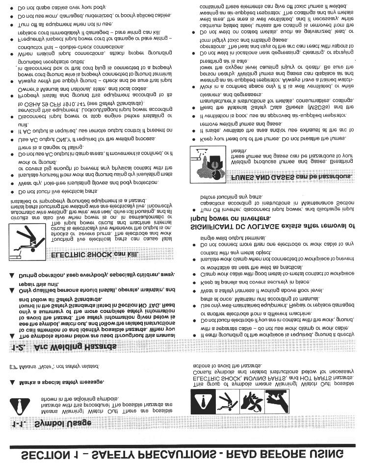
8 1.0 INTRODUCTION Your new stud welding equipment has been carefully constructed using the finest components and material available. Used properly, this equipment will give you many years of profitable, efficient service. The system incorporates the latest in engineering advances for complete, reliable end welding of mild steel, stainless steel and aluminum fasteners. A careful study of this manual will enable you to understand how the welder operates to insure proper performance under all conditions. 2.0 WARRANTY The electrical and mechanical components of the stud welder are thoroughly performance inspected prior to assembly in the welder. The assembled welder is completely performance checked. The welder is delivered to you in functional electro-mechanical condition. All parts used in the assembly of the welder and its accessories are fully warranted for a period of 1 YEAR from the date of delivery. In addition, the welding capacitors are warranted for a period of 1 YEAR from the date of delivery. The printed circuit boards used in all proweld equipment are warranted for a period of 3 years. Under the warranty, the manufacturer reserves the right to repair or replace, at their option, defective parts which fail during the guarantee period. Notice of any claim for warranty repair or replacement must be furnished to the manufacturer by the purchaser within ten (10) days after the defect is first discovered. The manufacturer does not assume any liability for paying shipping cost or any labor or materials furnished where such cost are not expressly authorized in writing. The manufacturer does not warrant any parts or accessories against failures resulting from misuse, abuse, improper installation, maladjustment, or use not in accordance with the operating instructions furnished by the manufacturer. The warranty is valid only when studs are purchased from sources approved by the manufacturer or are of identical specifications to the manufacturer s 3.0 UNPACKING YOUR UNIT Upon receipt of your unit, place it as close as possible to the point of installation before unpacking it. Once the unit is unpacked, it is recommended that you inspect it for any physical damage that may have occurred in shipping. Your unit has been completely assembled and inspected at the factory. Upon receipt, the unit must be hooked up to the recommended incoming power before welding. Place the unit in a large enough area to provide adequate ventilation. Do not restrict the air flow around the front louvers or from the fan at the rear of the unit. Do not allow water to enter the unit in any way. 4.0 SUGGESTED SAFETY PRECAUTIONS In any welding operation, it is the responsibility of the welder to observe all safety rules to insure his or her personal safety and to protect those working in the area. Reference is directed without endorsement or recommendation to ANSI Z49.1, Safety in Welding and Cutting, and to AWG Publication A6,1-66, Recommended Safe Practices for Gas-Shielded Arc Welding. 4.1 Personal Safety Precautions 1. Always treat electricity with respect. Under open circuit conditions, the welding machines output voltage may be dangerous. 2. Don t work on live circuits or conductors. Disconnect the main power before checking the machine or performing any maintenance or repair operations. 3. Be sure the welding machine cabinet is properly grounded to a good electrical ground. Consult local electrical codes. 4. Never operate a welder in the rain, or operate a welder while standing in water. Avoid wearing wet or sweaty clothes when welding. 5. Don t operate with worn or poorly connected cables, and don t operate the weld gun with loose cable connections. Inspect all cables frequently for insulation failures, exposed wires, loose connections and repair as needed. 6. Don t overload welding cables or continue to operate with over heated cables. 7. Don t weld near flammable materials or liquids in or near the area, or on ducts or pipes carrying explosive gases. 8. Don t weld on containers which have held combustible or flammable materials, or on materials which give off flammable or toxic vapors when heated. PAGE 1
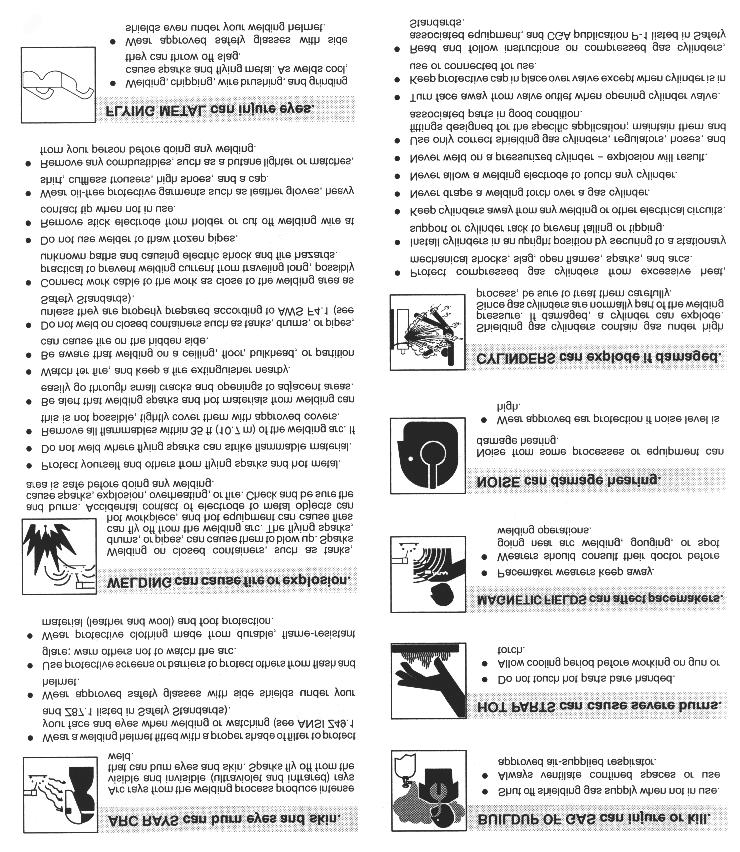
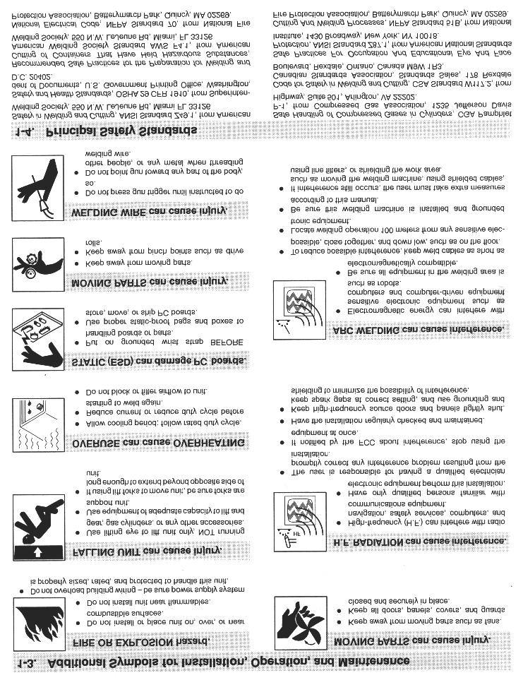
9 9. Be sure to provide proper ventilation when welding in a confined area. 10. Never look at the electric arc without wearing protective eye shields. PRIMARY WIRE DELAY TYPE FUSE SIZE-AWG GND SIZE IN AMPS 230V #4 # V #10 # V #10 # Always use the proper protective clothing, gloves, etc. 12. Never strike an arc when near a bystander who is unaware of the dangers of ultraviolet light to their eyes. 4.2 Power Supply Safety Precautions 1. Always connect the frame to the power supply to ground in accordance with the National Electrical Code and the manufacturer s recommendations. 2. Installation, servicing, or trouble shooting should be done by qualified personnel trained to work on this type of equipment. L1 L2 L3 L1 L2 L3 L1 L2 230 VOLT 460 VOLT 3. Before servicing this piece of equipment, turn off the disconnect switch at the fuse box. 4. When in operation, all the covers must be on the equipment. 5.0 GENERAL DESCRIPTION THE PROCESS Stud welding is a time saving tool which semi-automatically arc welds the FULL CROSS-SECTION of a weld stud to the base material in a fraction of a second and develops superior strength over normal arc welding procedures. Since the ARC-1200 stud welding system provides the proper arc length and allows you to select the proper arc time and welding current, the variables that affect weld quality are minimized. THE UNIT The ARC-1200 is a compact and portable stud welding power supply capable of welding studs thru 5/8 diameter weld base. The fully regulated power supply which operates on three phase power produces a smooth, stable welding arc. Both the weld time and weld current are infinitely adjustable for preciseness and repeatability. L3 575 VOLT Figure 1 Jumper Link Arrangement 6.0 ELECTRICAL INPUT REQUIREMENT This welding power source is designed to be operated from three-phase, 60 Hertz, AC power supply which has a line voltage rating that corresponds with one of the electrical input voltage shown on the nameplate or input data label. Consult the local electric utility if there is any question about the type of electrical system available at the installation site or how proper connections to the welding power source are to be made. The power unit should be operated from a seperately fused or circuit breaker protected circuit. The primary input voltage connection terminal board is located behind the access door on the rear panel. Install three primary leads plus one ground wire (see FIG. 1 for proper wire and fuse sizes) through the inlet hole in the rear of the unit. The primary cables connect to terminals labeled L or LINE. A FOURTH LEAD (GROUND CONNECTION) SHOULD BE FASTENED TO THE TERMINAL LABELED GND. The other end of the ground lead or cable should be attached to a suitable ground such as a water pipe, ground rod, ect. Use whatever grounding means is acceptable to the local PAGE 2

10 Figure 2 CONTROL PANEL FRONT CAUTION The stud labeled GND is connected to the unit chassis and is for grounding purposes only. Do not connect a wire from the terminal labeled GND to one of the three-phase line terminals as this may result in hot power unit chassis This unit is equipped with input voltage jumper links either installed or in a bag on the jumper link board to allow operation from different line voltages. If installed, the jumper links are positioned for the highest voltage stated on the nameplate or on the input data label. In either case the jumper links should always be checked to see if they are properly positioned for the voltage being used. Open the access door located on the lower portion of the rear panel to expose the jumper link board. If necessary, reposition the jumper links to match the line voltage being used. (see Figure 6.1) 7.0 CONTROL PANEL DESCRIPTION START/STOP PUSH BUTTON Momentarily depressing the START button will energize the main contactor inside the unit allowing all circuits to be activated and the the cooling fan to run. Momentarily depressing the STOP button will deactivate the entire machine. TIME RANGE SWITCH This switch is used to select either the A or B time range settings on the time adjustment knob. THERMAL/GUN FAULT LED INDICATOR The thermal/gun fault LED on indicates either the internal temperature in the main transformer has reached its maximum or there is a shorted gun solenoid or a shorted control cable. In either case the LED will stay on and lockout the gun from triggering. If there is a gun fault, by unplugging the gun control cable at the welder the LED will be off when the welder is first turned off then turned back on. If there is a thermal overload the LED will remain on until the temperature on the transformer comes down to a safe operating temperature. 8.0 GUN SET-UP 8.1 Plunge Length 1. A different and correctly sized chuck and ferrule grip are needed for each different stud diameter and style that will be welded (see PRO Accessories catalog for help in this area). The appropriate chuck, or stud holder, is inserted into the tapered chuck adapter and tapped lightly to insure a tight fit. The ferrule grip is inserted in the hole in the foot and secured with the locking screws to hold it in place. 2. Studs must NOT bind or hang up on the foot, ferrule grip, or ferrule during the entire stud welding process. To assure this, the foot/ferrule arrangement must be centered in relation to the stud to be welded. To assure centering, loosen the leg screws that hold the foot to the legs. Place a stud in the chuck and a ferrule in the ferrule grip. With the leg screws loosened, the foot will move freely in all directions. Adjust the foot so that the stud is centered in the ferrule and no contact occurs between the stud and the ferrule during retraction or forward plunge of the stud. PAGE 3
11 3. The plunge length is the amount of the stud exposed beyond the ferrule during initial set-up. Set the plunge by loosening the leg adjusting screws and moving the foot until the stud extends 1/8 to 3/16 past the end of the ferrule. Tighten the leg adjusting screws after setting the plunge and recheck centering to be sure the stud is aligned properly in the ferrule. 4. The lift height, which determines the arc length, has been preset at the factory and will automatically lift and plunge the stud during the welding process. Lift, is the distance the gun will raise the stud above the welding surface during the weld. This distance governs the voltage and the arc. Improper lift will cause unsatisfactory welds. Refer to paragraph 8-1 if it becomes necessary to adjust the lift height. 5. Make sure that the cables are connected to the power source (standard set-up is straight polarity - Negative to controller (or gun) and Positive (ground cable) to the work surface). 6. Turn on the power supply and adjust the current and time for the weld base diameter of the fastener to be welded. 7. Place the gun, loaded with the stud and ferrule, squarely against the grounded work surface. The main spring in the gun will take up the plunge length and the ferrule will seat against the base plate. DO NOT MOVE THE GUN DURING THE CY- CLE 8. Pull the trigger holding the gun completely still as above. The gun will lift the stud from the base plate and draw an arc. The end of the stud and the adjacent material of the base plate, will be melted by the weld arc. The gun will then plunge the stud into the molten pool, extinguishing the arc, to end the controlled portion of the weld 9. After the controlled weld cycle, allow the molten metal to solidify briefly with the work surface to assure completion of the cycle (about an extra second holding "still" after the weld is usually sufficient). 10. Remove the gun from the work by lifting straight away from the welded stud (this will assure better life to the gun's expendable accessories). The ferrule may now be removed by breaking it away from the welded stud to allow inspecttion of the weld results. After inspection of sample welds the gun can be adjusted, as per the step in this procedure, for optimum results. 8.2 Checking Gun Lift To measure lift, turn the stud welding unit on and set the timer to maximum time. (On certain units there may be a Lift Check switch available, and in these cases this switch can be used to check lift.) Trigger the gun in the air, or on a non-grounded or insulated surface, to observe the lift cycle. Measuring the distance the stud or gun mechanism moves equals lift - usually this can be easily done by visual observation or simple measurement against a static reference point (i.e. the ferrule properly seated in the ferrule grip). Recommended Lift Settings Stud Base Dia. Lift Setting Less than 1/2 1/16 1/2 through 3/4 3/32 Greater than 3/4 7/64 PAGE 4
12 When it does become necessary to adjust lift, you do so by removing the rear cap from the gun. This will expose the rear coil yoke assembly, the set screw and the lift adjusting screw (Loosen the set screw to avoid damaging the threads of the lift adjusting screw). To increase lift: turn the lift adjusting screw out (counter clockwise). To decrease lift: turn the lift adjusting screw in (clockwise). Once the lift has been set, tighten the set screw and replace the rear cap. 9.0 SETTING UP THE POWER SOURCE 9.1 Connections and settings. CAUTION Turn the power off before making connections a) Connect the male end of the GROUND CABLE to the positive GROUND terminal of the power supply, and secure the C clamp to the base plate. Make sure both connections are tight and the base metal is free of heavy paint or rust at the ground connection points. Table 9-1 Approximate Settings Stud Base Weld Weld Minimum Plate Inches mm Seconds Ampers Inches mm 1/ / / / / / Weld Test and Inspection Testing of weld quality beyond visual inspection varies with stud characteristics. Refer to AWS (American Welding Society) Structure Welding code AWS D.1Rev Welding procedures are covered in Sections 4.28 and Weld test and inspection is covered in Section 4.30, paragraphs 1 through 4. (American Welding Society, inc., 2501 N.W. 7th. Street, Miami, Fla ) b) Connect the male end of the COMBINATION CABLE SET to the negative GUN terminal of the power supply. c) Plug in the control cable portion of the COMBINATION CABLE SET into the control cable receptacle in the front of the power supply. d) Position the Time Range switch in either A or B depending on the required weld time. e) Set the Time adjustment required for the particular stud size. (see table 9-1) f) Set the Current adjustment to the current setting for the particular stud size. (see table 9-1) g) Turn on the power supply by depressing the START button. GOOD STUD A good full fillet STUD HANG UP Adjust foot to insure the stud is centered in the ferrule COLD Increase weld current and/or weld time HOT Reduce weld current and/or weld time figure 4 INSPECTION PAGE 5
13 A. Bend Test Repeatedly bend the stud away from its axis until failure occurs. B. Torque Test - Threaded Studs Twist the stud to point of failure. Apply a twisting tensile load by using a collar, washer and nut. C. Test Results In an acceptable weld, failure will occur in the stud material or tear out of a thin base plate. Failure in the weld requires adjustment of pocedure, weld time, weld current, or gun setup MAINTENANCE CAUTION CAUTION Read and follow the safety information at the begining of this section before proceding CABLES Every three months inspect cables for breaks in insulation. Repair or replace cables if insulation breaks are present. Clean and tighten connections at each inspection INTERNAL CLEANING Every six months blow or vacuum dust and dirt from th einside fo the welding power source. Remove the outer enclosure, and use a clean, dry airstream or vacuum suction for the cleaning operation. If dusty or dirty conditions are present, clean the unit monthly. Electric Shock Can Kill: Do not touch live electrical parts. Shut down welding power source, and disconnect input power before inspecting, maintaining, or servicing. Lockout/tagging procedures consist of padlocking line disconnect switch in the open position, removing fuses from fuse box, or shutting off and red-tagging circuit breaker or other disconnecting device. MOVING PARTS can cause serious injury. Keep away from moving parts. HOT SURFACES can cause severe burns. Allow cooling period before servicing. 1 AMP 1 AMP 1 AMP 1 AMP 1 AMP 45 AMP 25 AMP SLO BLO 25 AMP SLO BLO 25 AMP SLO BLO F9 F8 F7 F6 F5 F4 F3 F2 F1 Figure 5 FUSE BLOCK PAGE 6
14 11.0 TROUBLE SHOOTING Whenever possible, have a qualified electrician do the maintenance and trouble shooting work. Turn the input power off using the disconnect switch at the fuse box before working inside the machine. Trouble Possible Cause What To Do Unit trips off without 1. Defective main SCR. 1. Check for defective SCR and welding. replace. 2. Defective sustaining arc SCR. 2. check and replace. 3. Defective P.C.board 3. Replace. 4. Defective P.C. board. 4. Replace. 5. Shorted control cables. 5. Repair. Low output. 1. Input fuse blown. Unit is single 1. Replace fuse, repair input line. phase. Check for reason for fault Incorrect jumper link connection 2. Check jumper links on primary on primary board. board for proper voltage. 3. Defective P.C. board. 3. Replace. 4. Defective P.C. board. 4. Replace. 5. Defective current potentiometer. 5. Replace. Maximum output but 1. Defective P.C. board. 1. Replace. no control. 2. Open lead going to shunt 2. Repair broken leads on (shielded cable). connection. 3. Defective current potentiometer. 3. Replace. Gun does not lift. 1. Blown 5 amp fuse. 1. Check and replace fuse. 2. Defective P.C. board. 2. Replace. 3. Defective control cable or 3. Repair short in cable, replace gun coil. gun coil. 4. Defective P.C. board. 4. Replace. 5. Defective P.C. board. 5. Replace. 6. Blown 1 amp fuse 6. Check and replace fuse Gun lifts but does not 1. Blown 25 amp sustaining arc fuse. 1. Check and replace fuse. weld. 2. Defective sustaining arc SCR(s). 2. Replace bad part(s). 3. Defective P.C. board. 3. Replace. 4. Defective P.C. board 4. Replace. 5. Defective choke coil. 5. Check and Replace. 6. Open weld cable or bad weld 6. Check and Repair. ground connection. Gun lifts but does not 1. Defective P.C. board. 1. Replace. Plunge. 2. Defective time potentiometer. 2. Replace. PAGE 7

15 Figure 6 FRONT PANEL PARTS LIST Figure 7 PCB ENCLOSURE ITEM DESCRIPTION PART NUMBER 1 Knob Hi/Low Switch Red LED Green, Neon Light Start/Stop Operator (Open/Closed Contacts Needed for Operator) 6 Arc 1200 Decal SCR, Isolated, 25A 400V PCB, Current Control Choke Coil, (TR1600/450) PCB, Time CTR Circuit Board Hold Down PAGE 8

16 Figure 8 CONTROL UNIT-SIDE VIEW ITEM DESCRIPTION PART NUMBER Fan Blade /2 Hub for Fan Blade Fuse Holder Fuse 6A 250V Contactor Interloc Motor 1/8 HP PAGE 9

17 17 21, Figure 9 CONTROL UNIT-SIDE VIEW ITEM DESCRIPTION PART NUMBER 17 Norm. Open Contact Norm. Closed Contact M/Trans/1200/230/440/575/60HZ Wheels Axel Cap SCR SCR Clamp Buss Bar C/Trans/3000/60HZ/230/460/575V Shunt Front Caster (NOT SHOWN) PAGE 10
18 R129 R122 R120 V105 OP 109 OP 105 IC103 C109 + C111 R121 R149 D122 C110 + R123 R137 R124 ZD105 C106 + C107 R138 R143 C103 R136 R135 R150 R139 D118 R130 D124 D139 C112 R134 R128 R153 OFF D125 OP104 ON 1 2 OP 102 V106 IC104 C108 + V112 D111 R102 R144 D126 R131 R132 R127 R155 R101 D101 D127 R126 R104 D119 R103 D116 R145 D102 R110 R109 V104 D103 R114 R141 OP101 V111 VR101 C102 + R142 R115 D117 V103 D110 R111 R108 ZD102 R119 C104 + R154 R140 V108 R105 ZD101 IC102 D114 C105 + D104 D112 R116 OP110 IC101 D120 C115 R148 R118 R112 D115 R117 R147 R146 R125 V109 V110 V107 OP 103 D113 D109 D140 C114 OP 108 D131 D130 D129 R152 D136 D137 OP 106 C113 OP 107 R151 D133 D132 D135 D134 D138 Q101 D107 D108 C101 + D106 D105 ZD103 ZD104 V102 R107 R113 R133 D121 Figure 10 GUN TIME CONTROL P.C. BOARD P/N PAGE 11
19 PRO Figure 11 CURRENT CONTROL P.C. BOARD P/N R322 R323 D319 C307 R329 R324 IC304 R317 R308 R318 IC303 R314 R315 D317 IC302 R310 R311 IC301 R307 R306 V304 D316 R345 R332 R304 D318 R347 R331 C306 R330 R325 R346 R337 IC307 R344 R334 C309 R305 C310 R348 R326 R320 C304 ZD304 R316 R319 C303 D315 D310 R313 ZD303 ZD302 R312 C302 D305 ZD301 R309 C305 IC306 R301 D302 D301 D303 D304 D308 D309 D314 D306 D307 R303 D312 D311 R342 OP301 R340 ZD305 D328 D320 R339 R336 R338 R335 V301 IC305 Q301 C308 TR301 V302 R341 D321 V305 V303 R328 R327 R333 R350 D326 D327 OP303 OP302 R349 D324 D325 D323 D322 C301 C311 D313 R302 R321 R PAGE 12
20 MANUFACTURED BY PRO MADE IN THE U.S.A.
OPERATION/ MAINTENANCE MANUAL
 208 VERSION OPERATION/ MAINTENANCE MANUAL TABLE OF CONTENTS Section 1 SAFETY PRECAUTIONS PAGE 1.0 INTRODUCTION... 1 2.0 WARRANTY... 1 3.0 UNPACKING YOUR UNIT... 1 4.0 SUGGESTED SAFETY PRECAUTIONS... 1
ARC 1850 LIST OF FIGURES
 PAGE 1.0 INTRODUCTION... 1 2.0 WARRANTY... 1 3.0 UNPACKING YOUR UNIT... 1 4.0 SUGGESTED SAFETY PRECAUTIONS...... 1 4.1 PERSONAL SAFETY PRECAUTIONS. 1 4.2 POWER SUPPLY SAFETY PRECAUTIONS.. 2 5.0 GENERAL
TABLE OF CONTENTS LIST OF FIGURES
 TABLE OF CONTENTS Section 1 SAFETY PRECAUTIONS PAGE 1.0 INTRODUCTION... 1 2.0 WARRANTY... 1 3.0 UNPACKING YOUR UNIT... 1 4.0 SUGGESTED SAFETY PRECAUTIONS... 1 4.1 PERSONAL SAFETY PRECAUTIONS 1 4.2 POWER
OPERATION/ MAINTENANCE MANUAL
 OPERATION/ MAINTENANCE MANUAL TABLE OF CONTENTS PAGE 1.0 INTRODUCTION... 1 2.0 WARRANTY... 1 3.0 UNPACKING YOUR UNIT... 1 4.0 SUGGESTED SAFETY PRECAUTIONS...... 1 4.1 PERSONAL SAFETY PRECAUTIONS. 1 4.2
Cutlass Fasteners, Inc. 83 Vermont Ave., Unit 6, Warwick, RI Tel: (401) Fax: (401) cutlass-studwelding.com
 Fax: (401) cutlass-studwelding.com") MODEL : PHM-10 SHORT CYCLE WELD GUN PART NO. : PHM-10 SERIAL NO. : PLEASE READ THIS OPERATION AND MAINTENANCE MANUAL CAREFULLY BEFORE USING YOUR NEW CUTLASS STUD WELDER. COPYRIGHT CFI 2009 email: sales@
MODEL : PHM-10 SHORT CYCLE WELD GUN PART NO. : PHM-10 SERIAL NO. : PLEASE READ THIS OPERATION AND MAINTENANCE MANUAL CAREFULLY BEFORE USING YOUR NEW CUTLASS STUD WELDER. COPYRIGHT CFI 2009 email: sales@
Cutlass Fasteners, Inc. 83 Vermont Ave., Unit 6, Warwick, RI Tel: (401) Fax: (401) cutlass-studwelding.com
 Fax: (401) cutlass-studwelding.com") MODEL : BANTAM C8 BANTAM C10 PART NO. : 602-325A 602-343A SERIAL NO. : PLEASE READ THIS OPERATION AND MAINTENANCE MANUAL CAREFULLY BEFORE USING YOUR NEW CUTLASS STUD WELDER. COPYRIGHT CFI 2009 email: sales@
MODEL : BANTAM C8 BANTAM C10 PART NO. : 602-325A 602-343A SERIAL NO. : PLEASE READ THIS OPERATION AND MAINTENANCE MANUAL CAREFULLY BEFORE USING YOUR NEW CUTLASS STUD WELDER. COPYRIGHT CFI 2009 email: sales@
Cutlass Fasteners, Inc. 83 Vermont Ave., Unit 6, Warwick, RI Tel: (401) Fax: (401) cutlass-studwelding.com
 Fax: (401) cutlass-studwelding.com") MODEL : BANTAM C8 PART NO. : 602-325P SERIAL NO. : PLEASE READ THIS OPERATION AND MAINTENANCE MANUAL CAREFULLY BEFORE USING YOUR NEW CUTLASS STUD WELDER. COPYRIGHT CFI 2009 email: sales@ PAGE - 1 - WARRANTY
MODEL : BANTAM C8 PART NO. : 602-325P SERIAL NO. : PLEASE READ THIS OPERATION AND MAINTENANCE MANUAL CAREFULLY BEFORE USING YOUR NEW CUTLASS STUD WELDER. COPYRIGHT CFI 2009 email: sales@ PAGE - 1 - WARRANTY
OPERATION/ MAINTENANCE MANUAL
 OPERATION/ MAINTENANCE MANUAL TABLE OF CONTENTS 1.0 INTRODUCTION 1 2.0 WARRANTY 1 3.0 UNPACKING YOUR UNIT 1 4.0 SUGGESTED SAFETY PRECAUTIONS 1 5.0 GENERAL DESCRIPTION 2 6.0 THE CD ING PROCESS 2 7.0 POWER
OPERATION/ MAINTENANCE MANUAL
 OPERATION/ MAINTENANCE MANUAL TABLE OF CONTENTS 1.0 INTRODUCTION 1 2.0 WARRANTY 1 3.0 UNPACKING YOUR UNIT 1 4.0 SUGGESTED SAFETY PRECAUTIONS 1 5.0 GENERAL DESCRIPTION 2 6.0 THE CD ING PROCESS 2 7.0 POWER
OPERATION MANUAL. TWE Pin Welder. Model TWP-2 TRU WELD EQUIPMENT COMPANY 6400 N. HONEYTOWN ROAD SMITHVILLE, OHIO (330) Revision 2.
 Revision 2.") OPERATION MANUAL TWE Pin Welder Model TWP-2 TRU WELD EQUIPMENT COMPANY 6400 N. HONEYTOWN ROAD SMITHVILLE, OHIO 44677 (330) 725 7744 Revision 2.0 8/22/2013 TRU WELD EQUIPMENT LIMITED WARRANTY All goods
OPERATION MANUAL TWE Pin Welder Model TWP-2 TRU WELD EQUIPMENT COMPANY 6400 N. HONEYTOWN ROAD SMITHVILLE, OHIO 44677 (330) 725 7744 Revision 2.0 8/22/2013 TRU WELD EQUIPMENT LIMITED WARRANTY All goods
OPERATION MANUAL MODELS TWE-250 TWE-321 TWE-375 TRU WELD EQUIPMENT COMPANY 6400 N. HONEYTOWN ROAD SMITHVILLE, OHIO (330)
") OPERATION MANUAL MODELS TWE-250 TWE-321 TWE-375 TRU WELD EQUIPMENT COMPANY 6400 N. HONEYTOWN ROAD SMITHVILLE, OHIO 44677 (330) 669 2773 CONTENTS Section Description Pages 1 Introduction 3 2 External Features
OPERATION MANUAL MODELS TWE-250 TWE-321 TWE-375 TRU WELD EQUIPMENT COMPANY 6400 N. HONEYTOWN ROAD SMITHVILLE, OHIO 44677 (330) 669 2773 CONTENTS Section Description Pages 1 Introduction 3 2 External Features
OPERATION MANUAL. Model TWP-2. Toll free customer support:
 OPERATION MANUAL TWE StudPro Pin Welder Lite Model TWP-2 Downey, CA 9459 Washburn Rd. Downey, CA 90242 Phone- 800.252.1919 Fax- 562.862.3022 Hayward, CA Phoenix, AZ 2391 American TRU WELD Ave. EQUIPMENT
OPERATION MANUAL MODELS TWE-250 TWE-321 TWE-375 TRU WELD EQUIPMENT COMPANY 6400 N. HONEYTOWN ROAD SMITHVILLE, OHIO (330)
") OPERATION MANUAL MODELS TWE-250 TWE-321 TWE-375 TRU WELD EQUIPMENT COMPANY 6400 N. HONEYTOWN ROAD SMITHVILLE, OHIO 44677 (330) 669 2773 Version 1.3 Date 10/20/2010 TRU WELD EQUIPMENT LIMITED WARRANTY All
OPERATION MANUAL MODELS TWE-250 TWE-321 TWE-375 TRU WELD EQUIPMENT COMPANY 6400 N. HONEYTOWN ROAD SMITHVILLE, OHIO 44677 (330) 669 2773 Version 1.3 Date 10/20/2010 TRU WELD EQUIPMENT LIMITED WARRANTY All
QSSE, QSSEX INDUSTRIAL Battery Chargers
 C O R P O R A T IO N O P E R A T I N G I N S T R U C T I O N S QSSE, QSSEX INDUSTRIAL Battery Chargers INTRODUCTION The QSE line are electronically controlled float chargers. The batteries are brought
OPERATOR S MANUAL StudPro LiteXI Pin Welder Stud Welding Products, Inc
 OPERATOR S MANUAL StudPro LiteXI Pin Welder CONTENTS Description Pages Safety 2 Specifications and Features 3 Product Components 4-5 Screen Operation 6-8 Setup and Welding 9-11 CD Gun Exploded View 12
QPET, QPETXU Battery Chargers
 C O R P O R A T IO N O P E R A T I N G I N S T R U C T I O N S QPET, QPETXU Battery Chargers INTRODUCTION: The QPET line of chargers are designed for general purpose deep cycle batteries. They are an electronically
OPERATION INSTRUCTIONS
 www.r-techwelding.co.uk Email: sales@r-techwelding.co.uk Tel: 01452 733933 Fax: 01452 733939 ProArc 175 INVERTER ARC WELDER OPERATION INSTRUCTIONS Version 2017-10 2 3 Thank you for selecting the R-Tech
POWER PINNER CD HAND WELDER 7300 OPERATOR S MANUAL
 POWER PINNER CD HAND WELDER 7300 OPERATOR S MANUAL Copyright: April 7, 2014 Gripnail Corporation Revised: January 25, 2018 An Employee Owned Company 97 Dexter Road East Providence, Rhode Island 02914-2045
OPERATOR S MANUAL ACE - P100
 OPERATOR S MANUAL ACE - P100 Pin Welder TRU-WELD EQUIPMENT COMPANY www.truweldstudwelding.com (330) 725-7744 CONTENTS Description Pages Warranty Information 1 Safety 2 Specifications and Features 3 Product
OPERATION MANUAL TWE-375 CAPACITOR DISCHARGE WELDER
 OPERATION MANUAL TWE-375 CAPACITOR DISCHARGE WELDER TRU WELD EQUIPMENT COMPANY 6400 N. HONEYTOWN ROAD SMITHVILLE, OHIO 44677 (330) 725 7744 TWE@tfpcorp.com Version 1.0 Date 8/13/2013 TRU WELD EQUIPMENT
OBE, OBEXU, ON BOARD Battery Chargers
 C O R P O R A T IO N O P E R A T I N G I N S T R U C T I O N S OBE, OBEXU, ON BOARD Battery Chargers INTRODUCTION: These chargers are designed for the permanent installation on battery powered vehicles
OPERATOR S MANUAL. TW-i SERIES. Capacitor Discharge Stud Welder. MODELS: TW-i 250 TW-i 250CP TW-i 321 TW-i 375
 OPERATOR S MANUAL TW-i SERIES Capacitor Discharge Stud Welder MODELS: TW-i 250 TW-i 250CP TW-i 321 TW-i 375 TRU-WELD EQUIPMENT COMPANY www.truweldstudwelding.com (330) 725-7744 CONTENTS Description Pages
OPERATOR S MANUAL STUDPRO SERIES
 OPERATOR S MANUAL STUDPRO SERIES Capacitor Discharge Stud Welder MODELS: StudPro 2500XI StudPro 2500XIP StudPro 3125XI StudPro 3750XI CONTENTS Description Pages Safety 2 Specifications and Features 3 Product
OBAE, OBAEXU, ON BOARD Battery Chargers
 C O R P O R A T IO N O P E R A T I N G I N S T R U C T I O N S OBAE, OBAEXU, ON BOARD Battery Chargers INTRODUCTION: The OBAE line of chargers are designed for the permanent installation on battery powered
MMA 160S ARC/MMA WELDER OPERATION INSTRUCTIONS
 www.r-techwelding.co.uk MMA 160S ARC/MMA WELDER OPERATION INSTRUCTIONS 2 Thank you for selecting the R-Tech MMA160S Inverter Arc Welder. The MMA160S has many benefits over traditional Arc welders, including
Operator s Manual Model AC300 ARC Welder
 Operator s Manual Model AC300 ARC Welder WARNING: Do not assemble, install, or operate this equipment without reading ALL of this manual and the safety precautions and warnings illustrated in this manual.
24 VOLT AUTOMATIC BATTERY CHARGER PART NO
 24 VOLT AUTOMATIC BATTERY CHARGER PART NO. 957732 AC Input: DC Output: Battery Type: Specifications 230 volts, 50 hertz, 3.5 amps, single-phase 24 volts, 20 amps initially tapering to 6 amps 24 volt, 12
OPERATION MANUAL M185. MIG/flux wire feeder welder. Serial Number: Where Purchase: Date of purchased:
 OPERATION MANUAL M185 MIG/flux wire feeder welder Serial Number: Where Purchase: Date of purchased: CONTENT 1. Safety... 2 2. Electrical principle drawing... 4 3. Specifications... 5 4. Front and rear
Cutlass Fasteners, Inc. 83 Vermont Ave., Unit 6, Warwick, RI Tel: (401) Fax: (401) cutlass-studwelding.com
 Fax: (401) cutlass-studwelding.com") MODEL : PINTO YTEM/PKM-1B GUN PART NO. : C-1K ERIAL NO. : PLEAE READ THI OPERATION AND MAINTENANCE MANUAL CAREFULLY BEFORE UING YOUR NEW CUTLA TUD WELDER. COPYRIGHT CFI 2009 email: sales@ PAGE - 1 - WARRANTY
MODEL : PINTO YTEM/PKM-1B GUN PART NO. : C-1K ERIAL NO. : PLEAE READ THI OPERATION AND MAINTENANCE MANUAL CAREFULLY BEFORE UING YOUR NEW CUTLA TUD WELDER. COPYRIGHT CFI 2009 email: sales@ PAGE - 1 - WARRANTY
LESTRONIC II BATTERY CHARGER MODEL 07210
 LESTRONIC II BATTERY CHARGER MODEL 07210 PLEASE SAVE THESE IMPORTANT SAFETY AND OPERATING INSTRUCTIONS For correct operation of the equipment, it is important to read and be familiar with this entire manual
MODEL ELC-12/60-D BATTERY CHARGER
 *32198* NATIONAL RAILWAY SUPPLY Installing, Operating and Service Instructions for the 12/60 Solid State Charger MODEL ELC-12/60-D BATTERY CHARGER PLEASE SAVE THESE IMPORTANT SAFETY AND OPERATING INSTRUCTIONS
Automatic taper of charge rate for superior battery life through good equalization of cells and low water use rate.
 FEATURES Automatic taper of charge rate for superior battery life through good equalization of cells and low water use rate. Silicon diodes with inherent surge protection operated at a conservative percentage
MICRO WELD MODEL AUF-8 HEAVY DUTY FERROUS BUTT WELDERS MICRO PRODUCTS COMPANY SERVICE MANUAL
 MICRO WELD MODEL AUF-8 HEAVY DUTY FERROUS BUTT WELDERS MICRO PRODUCTS COMPANY SERVICE MANUAL 1 TABLE OF CONTENTS 1.0 SPECIFICATIONS 2.0 GENERAL OPERATING INSTRUCTIONS 3.0 BASIC OPERATING PARTS 4.0 BASIC
CDMF110 PINSPOTTER OWNER S MANUAL MACHINERY DIVISION
 CDMF110 c d m f 1 1 CDMF110 PINSPOTTER OWNER S MANUAL MACHINERY DIVISION UNIT INSTRUCTIONS Please follow all CDMF110 Safety Instructions. Contact your Duro Dyne Tech Service if you have any operating questions.
PBA Series Prelube Controls
 VARNA Products Engineered Innovation PBA Series Prelube Controls Simple, Compact, Industrial Full featured control for running prelube from the control or from a remote station Easy internal wiring connections
POWER PINNER HAND WELDER 7200 OPERATOR S MANUAL
 POWER PINNER HAND WELDER 7200 OPERATOR S MANUAL Copyright: January 5, 2009 Revised: November 24, 2014 Serial No. 0901189 - Gripnail Corporation An Employee Owned Company 97 Dexter Road East Providence,
LESTRONIC II BATTERY CHARGER BUILT-IN OR PORTABLE CHARGERS
 LESTRONIC II BATTERY CHARGER BUILT-IN OR PORTABLE CHARGERS PLEASE SAVE THESE IMPORTANT SAFETY AND OPERATING INSTRUCTIONS For correct operation of the equipment, it is important to read and be familiar
AUTOMATIC BURNISHER MODEL FURY 21 HSB
 AUTOMATIC BURNISHER MODEL FURY 21 HSB INTRODUCTION OPERATING & MAINTENANCE INSTRUCTIONS This operator s book has important information for the use and safe operation of this machine. Read this book carefully
MODEL ELC-12/40-CVM-D BATTERY CHARGER
 NATIONAL RAILWAY SUPPLY MODEL ELC-12/40-CVM-D BATTERY CHARGER Installing, Operating and Service Instructions for the ELC-12/40-CVM-D Solid State Charger PLEASE SAVE THESE IMPORTANT SAFETY AND OPERATING
MICRO WELD MODEL DP1 & DP2 HEAVY DUTY NON-FERROUS BUTT WELDERS MICRO PRODUCTS COMPANY SERVICE MANUAL
 MICRO WELD MODEL DP1 & DP2 HEAVY DUTY NON-FERROUS BUTT WELDERS MICRO PRODUCTS COMPANY SERVICE MANUAL 1 TABLE OF CONTENTS 1.0 SPECIFICATIONS 2.0 GENERAL OPERATING INSTRUCTIONS 3.0 BASIC OPERATING PARTS
CALTRAP INSTALLATION AND OPERATIONS MANUAL
 INSTALLATION AND OPERATIONS MANUAL NOTE Please read this entire installation and operations manual before energizing the. Safety Considerations: Installing and servicing capacitor equipment can be hazardous.
NSGV PT-1000 PORTABLE WELDING STATION I, O & M MANUAL
 APPLICATION OF DUST CONTROL EQUIPMENT: CAUTION - Warning Improper operation of dust control system may contribute to conditions in the work area or facility that could result in severe personal injury
LESTRONIC II BATTERY CHARGER MODEL 19740
 *01679* LESTRONIC II BATTERY CHARGER MODEL 19740 PLEASE SAVE THESE IMPORTANT SAFETY AND OPERATING INSTRUCTIONS For correct operation of the equipment, it is important to read and be familiar with this
MODEL 7100 PORTABLE PIN WELDER OPERATOR S MANUAL
 Model 7100 Portable Pin Welder MODEL 7100 PORTABLE PIN WELDER OPERATOR S MANUAL Copyright: March 22, 2005 Revised: December 20, 2016 Gripnail Corporation An Employee Owned Company 97 Dexter Road East Providence,
D-Series Blowers and Exhausters
 Operation and Maintenance Manual D-Series MONOXIVENT - SOURCE CAPTURE SYSTEMS - info@ Oct. - 2015 MONOXVENT BLOWERS AND EXHAUSTERS D05-1 D05-3 D10-1 D10-3 D15-1 D15-3 D20-1 D20-3 D30-1 D30-3 ½ HP TEFC
TURNING ROLLS 00338OG WARNINGS, SAFEGUARDS & OPERATING INSTRUCTIONS
 TURNING ROLLS 00338OG091207 WARNINGS, SAFEGUARDS & OPERATING INSTRUCTIONS Warnings and Safeguards for Welding and Cutting Operations IMPORTANT - Protect yourself and others! Remember that safety depends
Compressor Duty Motor - 1 HP. Model 40132
 Compressor Duty Motor - 1 HP Model 40132 Assembly and Operating Instructions 3491 Mission Oaks Blvd., Camarillo, CA 93011 Visit our web site at http://www.harborfreight.com Copyright 2002 by Harbor Freight
AIR COMPRESSOR OPERATING INSTRUCTION AND PARTS LIST
 AIR COMPRESSOR OPERATING INSTRUCTION AND PARTS LIST BELT TYPE IMPORTANT PLEASE MAKE CERTAIN THAT THE PERSON WHO IS TO USE THIS EQUIPMENT CAREFULLY READS AND UNDERSTANDS THESE INSTRUCTIONS BEFORE STARTING
User s Manual D-Series Blowers and Exhausters
 User s Manual D-Series Blowers and Exhausters D05-1 ½ HP TEFC 115/230 VOLTS, 1 PH D05-3 ½ HP TEFC 208/230/460 VOLTS, 3 PH D10-1 1 HP TEFC 115/230 VOLTS, 1 PH D10-3 1 HP TEFC 208/230/460 VOLTS, 3 PH D15-1
Maintenance Manual 13 AMPERE POWER SUPPLY 19A704647P1-P3. Mobile Communications LBI-31801C
 C Mobile Communications 13 AMPERE POWER SUPPLY 19A704647P1-P3 CAUTION THESE SERVICING INSTRUCTIONS ARE FOR USE BY QUALI- FIED PERSONNEL ONLY. TO AVOID ELECTRIC SHOCK DO NOT PERFORM ANY SERVICING OTHER
LESTRONIC II BATTERY CHARGER TAYLOR-DUNN MODEL TYPE 24LC25-8ET
 LESTRONIC II BATTERY CHARGER TAYLOR-DUNN 79-301-10 MODEL 13110-32 TYPE 24LC25-8ET AC Supply: DC Output: Battery Capacity: Specifications 120 volts, 60 Hertz, single-phase 24 volts, 32 amps Use only on
SHORT-STOP. Electronic Motor Brake Type G. Instructions and Setup Manual
 Electronic Motor Brake Type G Instructions and Setup Manual Table of Contents Table of Contents Electronic Motor Brake Type G... 1 1. INTRODUCTION... 2 2. DESCRIPTION AND APPLICATIONS... 2 3. SAFETY NOTES...
PRODUCT MANUAL TILE CUTTING MACHINE. . Operation. Parts List and Diagram SPECIFICATIONS CAUTION:
 FLORCRAFTT TM PRODUCT MANUAL SKU NUMBER 709-4242 SERIAL NUMBER: CAUTION: FOR YOUR OWN SAFETY READ INSTRUCTION MANUAL COMPLETELY AND CAREFULLY BEFORE OPERATING THIS 7 TILECUTTING MACHINE SPECIFICATIONS
BL7000 SYSTEM OPERATING MANUAL
 BL7000 SYSTEM OPERATING MANUAL REV 2.0 208 / 230V COPYRIGHT 1995 Xenotech, Inc. PAGE 1 POWER INPUT CONNECTOR WIRING INSTRUCTIONS THE INPUT POWER REQUIREMENTS FOR A 7 KW POWER SUPPLY ARE AS FOLLOWS. VOLTAGE
CLEAN POWER TM CPS Series Operator s Manual
 12 Test Equipment CLEAN POWER TM CPS Series Operator s Manual Power Supply / Maintenance Charger for 12 Volt Systems The CPS series of power supplies / maintenance chargers are the ultimate in supplying
User s Manual and Operating Instructions
 User s Manual and Operating Instructions Model Numbers: CL-36-BDF-A, CL-42-BDF-A, CL-48-BDF-A E355088 READ AND SAVE THESE INSTRUCTIONS IMPORTANT: Read and understand all of the instructions in this manual
HVF110, 210, 310, 410HD
 342 N. Co. Rd. 400 East Valparaiso, IN 46383 219-464-8818 Fax 219-462-7985 www.heatwagon.com Installation and Maintenance Manual Please retain this manual for future reference. HVF110, 210, 310, 410HD
WELDING FUME EXHAUSTERS & ARMS
 WELDING FUME EXHAUSTERS & ARMS The Ace 75 Series is our flexible and effective line of welding fume exhausters and extraction arms for shops that elect to exhaust their weld fumes outdoors instead of through
INSTRUCTIONS FOR THE RELIANCE CONTROLS ARM SERIES AUTOMATIC TRANSFER SWITCH
 INSTRUCTIONS FOR THE RELIANCE CONTROLS ARM SERIES AUTOMATIC TRANSFER SWITCH THE RELIANCE CONTROLS ARM SERIES AUTOMATIC TRANSFER SWITCH IS NOT FOR "DO-IT-YOURSELF" INSTALLATION. It must be installed by
MODEL 6010A 6 12 VOLT BATTERY CHARGER ASSOCIATE
 MODEL 600A 6 VOLT BATTERY CHARGER ASSOCIATE IMPORTANT SAFETY INSTRUCTIONS. SAVE THESE INSTRUCTIONS. This manual contains important safety and operating instructions for the battery charger you have purchased.
TWE Operations Manual
 HEAVY-DUTY STUD GUN Operations Manual The TWE17000 has been designed to fit comfortably for all hands, including when wearing a work glove. The neck of the handle has been tapered so that when grasped,
I. INSTALLATION INSTRUCTIONS
 I. INSTALLATION INSTRUCTIONS IT SHALL BE THE RESPONSIBILITY OF THE INSTALLER OF SELF--CONTAINED COMPACTORS TO INSTALL SELF--CONTAINED COMPACTORS IN ACCORDANCE WITH APPLICABLE CODES, LOCAL ORDINANCES, AND
36 VOLT AUTOMATIC BATTERY CHARGER PART NO
 36 VOLT AUTOMATIC BATTERY CHARGER PART NO. 957727 AC Supply: DC Output: Battery Type: Specifications 120 volts, 60 Hertz, 10 amps, single-phase 36 volts, 20 amps initially tapering to 6 amps 36 volt, 18
MULTIVOLTAGE PORTABLE BATTERY CHARGER MVM
 _ M MULTIVOLTAGE PORTABLE BATTERY CHARGER MVM User's MANUAL Code: MVM Version: 01-BF Date: OCT 2005 Page 1/10 _ 1. INTRODUCTION Before starting to use your Energic plus MVM battery charger, please take
ACC Series Power Conditioner OPERATION & INSTALLATION MANUAL
 ACC Series Power Conditioner OPERATION & INSTALLATION MANUAL PHASETEC digital power conditioners are designed to safely operate electrical equipment in the harshest power quality environments. With a wide
MICRO WELD MODEL AD 6-10 HEAVY DUTY NON-FERROUS BUTT WELDERS MICRO PRODUCTS COMPANY SERVICE MANUAL
 MICRO WELD MODEL AD 6-10 HEAVY DUTY NON-FERROUS BUTT WELDERS MICRO PRODUCTS COMPANY SERVICE MANUAL 1 TABLE OF CONTENTS 1.0 SPECIFICATIONS 2.0 GENERAL OPERATING INSTRUCTIONS 3.0 BASIC OPERATING PARTS 4.0
ACCUSENSE CHARGE SERIES ON/OFF BOARD FULLY AUTOMATIC BATTERY CHARGER
 ACCUSENSE CHARGE SERIES ON/OFF BOARD FULLY AUTOMATIC BATTERY CHARGER SPECIFICATIONS: *Photo for reference only* Part number 8890439 Mode Select: Selects Battery Type Refer to Section 6. IMPORTANT: READ
MIG Welders. Operator s Manual Model 135WFG Wire Feed Welder
 Operator s Manual Model 135WFG Wire Feed Welder MIG Welders WARNING: Do not assemble, install, or operate this equipment without reading ALL of this manual and the safety precautions and warnings illustrated
User s Manual. Automatic Switch-Mode Battery Charger
 User s Manual Automatic Switch-Mode Battery Charger IMPORTANT Read, understand, and follow these safety rules and operating instructions before using this battery charger. Only authorized and trained service
MPPC40DVI OWNER S MANUAL
 MPPC40DVI OWNER S MANUAL 4/2017 WARNING: Read carefully and understand all ASSEMBLY AND OPERATION INSTRUCTIONS before operating. Failure to follow the safety rules and other basic safety precautions may
Hazardous Location Direct-Drive Exhaust Fans. Operating Instructions & Parts Manual
 Operating Instructions & Parts Manual EN Hazardous Location Direct-Drive Exhaust Fans Models 10D996 thru 10D999, 10E001 thru 10E007, 10E009 thru 10E020, 32ZN53 and 32ZN54 474904 PLEASE READ AND SAVE THESE
OPERATOR'S MANUAL IMPORTANT SAFETY INSTRUCTIONS
 ASSOCIATED OPERATOR'S MANUAL IMPORTANT SAFETY INSTRUCTIONS MODEL 6366 12 VOLT, 0-20 AMP 4 X 20 BATTERY CHARGER 1. SAVE THESE INSTRUCTIONS. This manual contains important safety and operating instructions
A1P OPERATING MANUAL
 A1P OPERATING MANUAL TABLE OF CONTENTS Introduction... p. 2 Features... p. 2 Description... p. 3 Theory of Operation... p. 3 Installation... p. 4 Electrical Connections... p. 5 Options... p. 6 Warranty...
MMW220PC OWNER S MANUAL
 MMW220PC OWNER S MANUAL 12/2015 WARNING: Read carefully and understand all ASSEMBLY AND OPERATION INSTRUCTIONS before operating. Failure to follow the safety rules and other basic safety precautions may
INDUSTRY WIDE LABOR-MANAGEMENT SAFETY COMMITTEE
 INDUSTRY WIDE LABOR-MANAGEMENT SAFETY COMMITTEE SAFETY BULLETIN #23 GUIDELINES FOR WORKING WITH LIGHTING SYSTEMS AND OTHER ELECTRICAL EQUIPMENT All electrical systems and electrically energized equipment
1200W Paint DRYING Lamp
 1200W Paint DRYING Lamp Model 97641 Assembly And Operation Instructions Diagrams within this manual may not be drawn proportionally. Due to continuing improvements, actual product may differ slightly from
SKILL ATTACK PITCHING MACHINE PATENTS APPLIED FOR INSTRUCTION MANUAL. Includes: OPERATION SETUP USE & CARE SERVICE
 VOLLEYBALL SKILL ATTACK PITCHING MACHINE PATENTS APPLIED FOR INSTRUCTION MANUAL Includes: OPERATION SETUP USE & CARE SERVICE REV083115 Sports Attack, LLC. 800-717-4251 sportsattack.com WARRANTY STATEMENT
MODEL 6017 OPERATOR'S MANUAL
 MODEL 6017 OPERATOR'S MANUAL ASSOCIATE D IMPORTANT SAFETY INSTRUCTIONS 1. SAVE THESE INSTRUCTIONS. This manual contains important safety and operating instructions for the battery charger you have purchased.
Installation and Service Manual for SRC25, SRC252, SRC50, SRC502, SRC75, SRC752
 Rocking Piston Compressors Installation and Service Manual for SRC25, SRC252, SRC50, SRC502, SRC75, SRC752 Thank you for purchasing the Stratus SRC series rocking piston compressor. This instruction manual
TYPE KF UNDER-FREQUENCY RELAY A. Figure 1: Type KF Relay for 60 Hertz without Case. (Front & Rear View.) Front View Rear View
 Front View Rear View") 41-503.21A TYPE KF Front View Rear View Figure 1: Type KF Relay for 60 Hertz without Case. (Front & Rear View.) 2 TYPE KF 41-503.21A lower pin bearing, which is mounted on the frame, with respect to the
41-503.21A TYPE KF Front View Rear View Figure 1: Type KF Relay for 60 Hertz without Case. (Front & Rear View.) 2 TYPE KF 41-503.21A lower pin bearing, which is mounted on the frame, with respect to the
MODEL A97 SERIES. Switchmode Utility Rectifier/Battery Charger ECN/DATE
 MODEL A97 SERIES Switchmode Utility Rectifier/Battery Charger CPN108172 ISSUE DATE: 16071 7/03 ECN/DATE 106 BRADROCK DRIVE DES PLAINES, IL. 60018-1967 (847) 299-1188 FAX: (847)299-3061 Page 1 of 7 INSTRUCTION
801 BUSINESS CENTER DRIVE MOUNT PROSPECT, ILLINOIS Ext. 322
 277-999 ELECTRIC CORP. 801 BUSINESS CENTER DRIVE MOUNT PROSPECT, ILLINOIS 800-621-5485 Ext. 322 Send Warranty Product Repairs to: 605 South Vermilion, Suite C, Brownsville, TX 78521-6851 Call Customer
Stick/Mig Capability Welding Excellence Modular Construction Environment Protected 2,000 Watt AC Power for Tools
 E300 3+2 Electric Welder Service Manual Stick/Mig Capability Welding Excellence Modular Construction Environment Protected 2,000 Watt AC Power for Tools SVM_E300 3+2 SAFETY Arc Welding Safety Precautions
PC40 INVERTER PLASMA CUTTER 230V 40A SUM OWNER S MANUAL
 PC40 INVERTER PLASMA CUTTER 230V 40A SUM-900990 OWNER S MANUAL WARNING: Read carefully and understand all ASSEMBLY AND OPERATION INSTRUCTIONS before operating. Failure to follow the safety rules and other
PROCESS ELECTRONICS CORPORATION
 MINIVERTER MANUAL PROCESS ELECTRONICS CORPORATION 100 BRICKYARD ROAD MOUNT HOLLY, NORTH CAROLINA 28120 TELEPHONE (800) 421-9107 FAX (704) 827-9595 SALES@PECRECTIFIER.COM WWW.PECRECTIFIER.COM SOLID STATE
A48 / A48B (base plate) BATTERY CHARGER
 BATTERY CHARGER") A48 / A48B (base plate) BATTERY CHARGER CPN41054 ISSUE DATE: 12315-8/98 ECN/DATE 106 BRADROCK DRIVE DES PLAINES, IL. 60018-1967 (847) 299-1188 FAX: (847)299-3061 15349-07-07/02 16041 6/03 14575-2/01 INSTRUCTION
A48 / A48B (base plate) BATTERY CHARGER CPN41054 ISSUE DATE: 12315-8/98 ECN/DATE 106 BRADROCK DRIVE DES PLAINES, IL. 60018-1967 (847) 299-1188 FAX: (847)299-3061 15349-07-07/02 16041 6/03 14575-2/01 INSTRUCTION
MICRO WELD MODEL AD 3-5 HEAVY DUTY NON-FERROUS BUTT WELDERS MICRO PRODUCTS COMPANY SERVICE MANUAL
 MICRO WELD MODEL AD 3-5 HEAVY DUTY NON-FERROUS BUTT WELDERS MICRO PRODUCTS COMPANY SERVICE MANUAL 1 TABLE OF CONTENTS 1.0 SPECIFICATIONS 2.0 GENERAL OPERATING INSTRUCTIONS 3.0 BASIC OPERATING PARTS 4.0
INSTALLATION, OPERATION AND MAINTENANCE MANUAL WALL EXHAUST FANS BELT & DIRECT DRIVE XB, HV, HVA, ADD, DDS, DDP
 INSTALLATION, OPERATION AND MAINTENANCE MANUAL WALL EXHAUST FANS BELT & DIRECT DRIVE XB, HV, HVA, ADD, DDS, DDP The purpose of this manual is to aid in the proper installation and operation of the fans.
RediCoat by Nordson. Hopper and VBF Dolly Systems. Customer Product Manual Part A Issued 10/07
 RediCoat by Nordson Hopper and VBF Dolly Systems Customer Product Manual Part 1082648A Issued 10/07 This document is subject to change without notice. Nordson Corporation Amherst, Ohio USA 2 Table of Contents
MMWP125I OWNER S MANUAL
 MMWP125I OWNER S MANUAL 1/2017 WARNING: Read carefully and understand all ASSEMBLY AND OPERATION INSTRUCTIONS before operating. Failure to follow the safety rules and other basic safety precautions may
The Da-Lite Difference.
 The Da-Lite Difference. Instruction Book for Large Advantage Electrol DA-LITE SCREEN COMPANY, INC. 3100 North Detroit Street Post Office Box 137 Warsaw, Indiana 46581-0137 Phone: 574-267-8101 800-622-3737
Dispenser & Warmer RIC-1909 RIC-1909EXP
 Dispenser & Warmer RIC-1909 RIC-1909EXP Safety Precautions CAUTION This equipment is designed and sold for commercial use only. This equipment is not to be used by the consumer in home use. Do not allow
COOKSON OWNER'S MANUAL
 COOKSON OWNER'S MANUAL FDO-A10 INDUSTRIAL DUTY FIRE DOOR OPERATOR R L I S T E D 3040233 US CONTROL PANEL SERIAL# OPERATOR SERIAL# 9001.DWG ECN 0959 REV 4 SPECIFICATIONS MOTOR TYPE:...INTERMITTENT HORSEPOWER:...1/8
INSTALLATION, OPERATION AND MAINTENANCE MANUAL WALL EXHAUST FANS BELT DRIVE XBL FANS
 INSTALLATION, OPERATION AND MAINTENANCE MANUAL WALL EXHAUST FANS BELT DRIVE XBL FANS The purpose of this manual is to aid in the proper installation and operation of the fans. These instructions are intended
VTC610 Series Voltage Converter. Installation & Operation Manual
 VTC610 Series Voltage Converter Installation & Operation Manual IMPORTANT SAFETY INSTRUCTIONS 1) SAVE THESE INSTRUCTIONS This manual contains important safety and operating instructions for this voltage
Lumina 28 Traction Drive Model: Battery Burnisher M28036TDQP OPERATION SERVICE PARTS CARE
 Lumina 28 Traction Drive Model: Battery Burnisher M28036TDQP OPERATION SERVICE PARTS CARE Table of Contents IMPORTANT SAFETY INSTRUCTIONS...1 OPERATING INSTRUCTIONS...2 INSPECTION...2 ELECTRICAL...2 BATTERIES...2
OPERATING INSTRUCTIONS. Note: 6V Charging. Requires Manual Shut Off.
 Requires Manual Shut Off. 6 / 2 AMP,, DUAL RATE BATTER TTERY CHARGER 45005 OPERATING INSTRUCTIONS E224783 E224783 Note: 6V Charging Due to continuing improvements, actual product may differ slightly from
Abbeon Cal, Inc. Model BD-50E HIGH FREQUENCY GENERATOR OPERATING MANUAL
 Abbeon Cal, Inc. Model BD-50E HIGH FREQUENCY GENERATOR OPERATING MANUAL DESCRIPTION. The Model BD-50E is a rugged tester designed for testing tank lining and other applications where extended use is necessary.
801 BUSINESS CENTER DRIVE MOUNT PROSPECT, ILLINOIS
 280-600 Send Warranty Product Repairs to: 1025 E. Thompson Ave., Hoopeston, IL 60942-0280. Call Customer Service if you have questions: 1-800-621-5485 A. IMPORTANT SAFETY INSTRUCTIONS 1. SAVE THESE INSTRUCTIONS
Marlow Series Cast Iron Swimming Pool Pumps
 INSTRUCTION MANUAL SECTION 360A AC1683 REVISION C INSTALLER: PLEASE LEAVE THIS MANUAL FOR THE OWNER'S USE. Marlow Series Cast Iron Swimming Pool Pumps 3B28EC 3B32EC PLEASE FILL IN DATA FROM YOUR PUMP NAMEPLATE