ARC 1850 LIST OF FIGURES
|
|
|
- Mae Gaines
- 6 years ago
- Views:
Transcription
1
2
3 PAGE 1.0 INTRODUCTION WARRANTY UNPACKING YOUR UNIT SUGGESTED SAFETY PRECAUTIONS PERSONAL SAFETY PRECAUTIONS POWER SUPPLY SAFETY PRECAUTIONS GENERAL DESCRIPTION ELECTRICAL INPUT REQUIREMENT CONTROL PANEL DESCRIPTION WELD GUN SETUP PLUNGE LENGTH CHECKING GUN LIFT PARTS LIST thru TROUBLE SHOOTING LIST OF FIGURES 1 JUMPER LINK ARRANGEMENT CONTROL PANEL FRONT STANDARD GUN SET-UP FUSE BLOCK CONTROL UNIT - FRONT CONTROL UNIT - REAR CONTROL UNIT -SIDE VIEW RECTIFIER, WELD BRIDGE ASSY PRINTED CIRCUIT BOARD ENCLOSURE GUN TIMER CONTROL PCB MONITOR PCB CURRENT CONTROL PCB
4
5
6
7
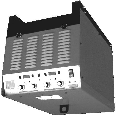
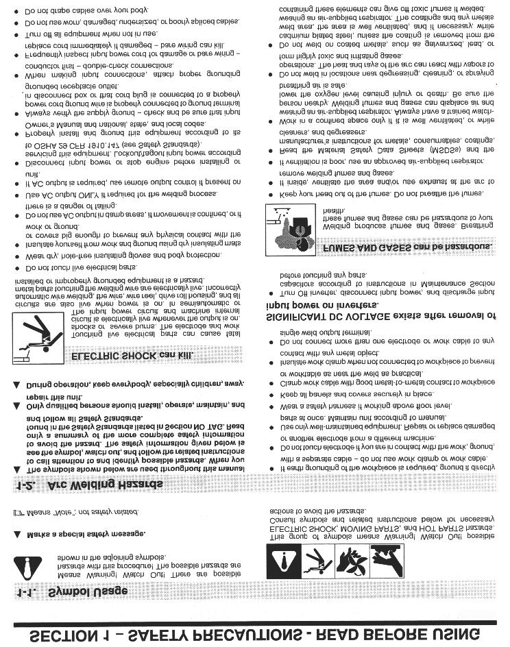
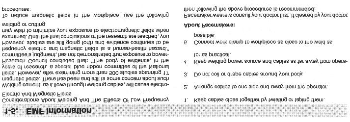
8 1.0 INTRODUCTION Your new stud welding equipment has been carefully constructed using the finest components and material available. Used properly, this equipment will give you many years of profitable, efficient service. The system incorporates the latest in engineering advances for complete, reliable end welding of mild steel, stainless steel and aluminum fasteners. A careful study of this manual will enable you to understand how the welder operates to insure proper performance under all conditions. 2.0 WARRANTY The electrical and mechanical components of the stud welder are thoroughly performance inspected prior to assembly in the welder. The assembled welder is also completely performance tested. All parts used in the assembly of the welder and its accessories are fully warranted for a period ninety (90) days for date of delivery. Under the warranty, the manufacturer reserves the right to repair or replace, at their option, any defective part or parts which fail during the warranty period. Notice of any claim for warranty repair or replacement must be furnished to the manufacturer by the purchaser within ten (10) days after the defect is first discovered. The manufacturer does not assume any liability for paying shipping costs or for any labor or material furnished where such costs are not expressly authorized in writing. The manufacturer does not warrant any parts or accessories against failures resulting from misuse, abuse, improper installation, maladjustment or use not in accordance with the operating instructions furnished by the manufacturer. The warranty is valid only when studs are purchased from sources approved by the manufacturer or are of identical specifications to the manufacturers. 3.0 UNPACKING YOUR UNIT Upon receipt of your unit, place it as close as possible to the point of installation before unpacking it. Once the unit is unpacked, it is recommended that you inspect it for any physical damage that may have occurred in shipping. Your unit has been completely assembled and inspected at the factory. Upon receipt, the unit must be hooked up to the recommended incoming power before welding. Place the unit in a large enough area to provide adequate ventilation. Do not restrict the air flow around the front louvers or from the fan at the rear of the unit. Do not allow water to enter the unit in any way. 4.0 SUGGESTED SAFETY PRECAUTIONS In any welding operation, it is the responsibility of the welder to observe all safety rules to insure his or her personal safety and to protect those working in the area. Reference is directed without endorsement or recommendation to ANSI Z49.1, Safety in Welding and Cutting, and to AWG Publication A6,1-66, Recommended Safe Practices for Gas-Shielded Arc Welding. 4.1 Personal Safety Precautions 1. Always treat electricity with respect. Under open circuit conditions, the welding machines output voltage may be dangerous. 2. Don t work on live circuits or conductors. Disconnect the main power before checking the machine or performing any maintenance or repair operations. 3. Be sure the welding machine cabinet is properly grounded to a good electrical ground. Consult local electrical codes. 4. Never operate a welder in the rain, or operate a welder while standing in water. Avoid wearing wet or sweaty clothes when welding. 5. Don t operate with worn or poorly connected cables, and don t operate the weld gun with loose cable connections. Inspect all cables frequently for insulation failures, exposed wires, loose connections and repair as needed. 6. Don t overload welding cables or continue to operate with over heated cables. 7. Don t weld near flammable materials or liquids in or near the area, or on ducts or pipes carrying explosive gases. 8. Don t weld on containers which have held combustible or flammable materials, or on materials which give off flammable or toxic vapors when heated. PAGE 1
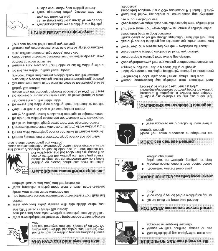
9 9. Be sure to provide proper ventilation when welding in a confined area. 10. Never look at the electric arc without wearing protective eye shields. 11. Always use the proper protective clothing, gloves, etc. 12. Never strike an arc when near a bystander who is unaware of the dangers of ultraviolet light to their eyes. 4.2 Power Supply Safety Precautions 1. Always connect the frame to the power supply to ground in accordance with the National Electric Code and the manufacturer s recommendation. 2. Installation, servicing or trouble shooting should be done by qualified personnel trained to work on this type of equipment. 3. Before servicing this piece of equipment, turn off the disconnect switch at the fuse box. 4. When in operation, all the covers must be on the equipment. 5.0 GENERAL DESCRIPTION THE PROCESS Stud welding is a time saving tool which semi-automatically arc welds the FULL CROSS-SECTION of a weld stud to the base material in a fraction of a second and develops superior strength over normal arc welding procedures. Since the ARC-1850 stud welding system provides the proper arc length and allows you to select the proper arc time and welding current, the variables that affect weld quality are minimized. THE UNIT The ARC-1850 is a fully regulated stud welding power supply that is available in a single or dual gun version. Both versions have the constant output feature that allows the unit to be used as a power source that can operate external stud welding control units. An added feature in the ARC-1850 is the ability to dial in the desired weld time and weld current before even making a weld. By selecting the setup mode, the weld time and current can be adjusted and displayed on the front panel s digital meters. A specially designed electronic gun control circuit has been incorporated in this system. If a fault condition occurs due to a shorted gun solenoid or a faulty control cable, the circuit will prevent gun triggering and eliminate damage to printed circuit boards. The ARC-1850 system is capable of welding studs from 12ga. to 3/4 diameter with precision and repeatability. 6.0 ELECTRICAL INPUT REQUIREMENT This welding power source is designed to be operated from three-phase, 60 Hertz, AC power supply which has a line voltage rating that corresponds with one of the electrical input voltage shown on the nameplate or input data label. Consult the local electric utility if there is any question about the type of electrical system available at the installation site or how proper connections to the welding power source are to be made. The ARC-1850 should be operated from a separate fused or circuit breaker protected circuit. Install three primary leads plus one ground wire (see tables for proper wire and fuse sizes) through the inlet hole in the rear of the unit, using proper strain relief. The primary cables connect to the terminals L or line. The fourth lead (ground connection) should be fastened to the welder from the ground bolt. The other end of the ground lead or cable should be attached to a suitable ground such as a water pipe, ground rod, etc. This unit is equipped with input voltage jumper links either installed or in a bag on the jumper link board to allow operation from different line voltages. If installed, the jumper links are positioned for the highest voltage stated on the nameplate or on the input data label. In either case the jumper links should always be checked to see if they are properly positioned for the voltage being used. Open the access door located on the lower portion of the rear panel to expose the jumper link board. If necessary, reposition the jumper links to match the line voltage being used. (see Figure 6.1). PAGE 2
10 L1 L2 L3 230V L1 L2 L3 460V L1 L2 L V Jumper Link connections Figure 1 Jumper Link Arrangement PRIMARY WIRE DELAY TYPE FUSE SIZE- AWG GND SIZE IN AMPS 230V NO.1(2) NO CAUTION The stud labeled GND is connected to the unit chassis and is for grounding purposes only. Do not connect a wire from the terminal labeled GND to one of the three-phase line terminals as this may result in hot power unit chas- 460V NO.4(6) NO V NO.4(6) NO.6 90 PAGE 3

11 Figure 2 CONTROL PANEL FRONT (DUAL GUN SYSTEM) 7.0 CONTROL PANEL DESCRIPTION START/STOP PUSH BUTTON Momentarily depressing the START button will energize the main contactor inside the unit allowing all circuits to be activated and the the cooling fan to run. Momentarily depressing the STOP button will deactivate the entire machine. STUD/CONSTANT OUTPUT SWITCH When this switch is in the stud position, the unit is a dedicated stud welding power supply with built in time and current controls. When in the constant output position the unit becomes a welding power supply that can operate an external control box. WELD/SETUP SWITCH This switch directs the digital panel meter to display either the setup parameters or the actual weld parameters. This switch must be in the weld position for the unit to weld. TIME/CURRENT SWITCH This switch selects either the weld time or weld current that is to be displayed on the digital meter. WELD TIME ADJUSTMENT Select: SETUP, TIME and adjust the time control knob until the digital meter displays the desired time. Return setup switch to WELD before attempting to weld. The weld time is adjustable from.1 to 1.6 seconds. WELD/CURRENT ADJUSTMENT Select: SETUP, CURRENT and adjust the current control knob until the digital meter displays the desired current. Return setup switch to WELD, before attempting to weld. Weld current is adjustable from 100 to 1900 amps. DIGITAL PANEL METERS Displays weld time or weld current. After a stud weld, the digital meter will automatically display the actual weld parameters. The meter will automatically reset and display the time or current for each weld. TRIGGER LED INDICATOR The trigger LED on indicates a complete circuit to the unit through the gun control cables and gun switch. This LED will turn on when the gun trigger is pressed. GUN FAULT LED INDICATOR The gun fault LED on indicates a shorted gun solenoid or a shorted control cable. The LED will stay on and lock out the gun from triggering. THERMAL LED INDICATOR The thermal LED on indicates the internal temperature has reached the maximum rated temperature in either the weld bridge or the main transformer. LED on will prevent the gun from being triggered. PAGE 4
12 8.0 WELD GUN SET-UP 8.1 Plunge Length 1. A different and correctly sized chuck and ferrule grip are needed for each different stud diameter and style that will be welded (see PRO WELD Accessories catalog for help in this area). The appropriate chuck, or stud holder, is inserted into the tapered chuck adapter and tapped lightly to insure a tight fit. The ferrule grip is inserted in the hole in the foot and secured with the locking screws to hold it in place. 2. Studs must NOT bind or hang up on the foot, ferrule grip, or ferrule during the entire stud welding process. To assure this, the foot/ferrule arrangement must be centered in relation to the stud to be welded. To assure centering, loosen the leg screws that hold the foot to the legs. Place a stud in the chuck and a ferrule in the ferrule grip. With the leg screws loosened, the foot will move freely in all directions. Adjust the foot so that the stud is centered in the ferrule and no contact occurs between the stud and the ferrule during retraction or forward plunge of the stud. 3. The plunge length is the amount of the stud exposed beyond the ferrule during initial set-up. Set the plunge by loosening the leg adjusting screws and moving the foot until the stud extends 1/8 to 3/16 past the end of the ferrule. Tighten the leg adjusting screws after setting the plunge and recheck centering to be sure the stud is aligned properly in the ferrule. 4. The lift height, which determines the arc length, has been preset at the factory and will automatically lift and plunge the stud during the welding process. Lift, is the distance the gun will raise the stud above the welding surface during the weld. This distance governs the voltage and the arc. Improper lift will cause unsatisfactory welds. Refer to paragraph 8-1 if it becomes necessary to ad- PAGE 5 5. Make sure that the cables are connected to the power source (standard set-up is straight polarity - Negative to controller (or gun) and Positive (ground cable) to the work surface). 6. Turn on the power supply and adjust the current and time for the weld base diameter of the fastener to be welded. 7. Place the gun, loaded with the stud and ferrule, squarely against the grounded work surface. The main spring in the gun will take up the plunge length and the ferrule will seat against the base plate. DO NOT MOVE THE GUN DURING THE WELD CYCLE 8. Pull the trigger holding the gun completely still as above. The gun will lift the stud from the base plate and draw an arc. The end of the stud and the adjacent material of the base plate, will be melted by the weld arc. The gun will then plunge the stud into the molten pool, extinguishing the arc, to end the controlled portion of the weld cycle. 9. After the controlled weld cycle, allow the molten metal to solidify briefly with the work surface to assure completion of the cycle (about an extra second holding "still" after the weld is usually sufficient). 10. Remove the gun from the work by lifting straight away from the welded stud (this will assure better life to the gun's expendable accessories). The ferrule may now be removed by breaking it away from the welded stud to allow inspecttion of the weld results. After inspection of sample welds the gun can be adjusted, as per the step in this procedure, for optimum results.
13 8.2 Checking Gun Lift To measure lift, turn the stud welding unit on and set the timer to maximum time. (On certain units there may be a Lift Check switch available, and in these cases this switch can be used to check lift.) Trigger the gun in the air, or on a non-grounded or insulated surface, to observe the lift cycle. Measuring the distance the stud or gun mechanism moves equals lift - usually this can be easily done by visual observation or simple measurement against a static reference point (i.e. the ferrule properly seated in the ferrule grip). Recommended Lift Settings. Stud Base Dia. Lift Setting Less than 1/2 1/16 1/2 through 3/4 3/32 Greater than 3/4 7/64 When it does become necessary to adjust lift, you do so by removing the rear cap from the gun. This will expose the rear coil yoke assembly, the set screw and the lift adjusting screw (Loosen the set screw to avoid damaging the threads of the lift adjusting screw). To increase lift: turn the lift adjusting screw out (counter clockwise). To decrease lift: turn the lift adjusting screw in (clockwise). Once the lift has been set, tighten the set screw and replace the rear cap. F12 F11 F10 F9 F8 F7 F6 F5 F4 F3 F2 Figure 4 FUSE BLOCK (Dual gun version shown) 1 AMP 1 AMP 1 AMP 1 AMP 1 AMP 1 AMP 1 AMP 5 AMP CERAMIC 25 AMP SLO BLO 25 AMP SLO BLO 25 AMP SLO BLO PAGE 6
 9.0 PARTS LIST ITEM DESCR")
14 Figure 5 Control Unit (Front View) 9.0 PARTS LIST ITEM DESCRIPTION PART NUMBER 1 Switch On/Off Operator N.O. Contact N.C. Contact Power Light (Green Neon) Knob k Potentiometer Red LED Panel Meter Green LED Amber LED Positive Output Terminal Pole Panel Mounted Connector PAGE 7

15 Figure 6 Control Unit Rear 9.0 PARTS LIST ITEM DESCRIPTION PART NUMBER 12 Fuse 6 amp 600 volt Control Transformer Fan Blade Fan Motor Start Contactor PAGE 8

16 FRONT OF UNIT Figure 7 Control Unit Side View 9.0 PARTS LIST ITEM DESCRIPTION PART NUMBER 17 Main Transformer Shunt PAGE 9


17 19 20 Figure 8 RECTIFIER, SCR ASSEMBLY SIDE AND TOP VIEW PARTS LIST ITEM DESCRIPTION PART NUMBER 19 Weld SCR Thermostat Weld SCR Clamp Weld SCR PAGE 10


18 Figure 9 Printed Circuit Board Enclosure Top and Side View Front of Unit PARTS LIST ITEM DESCRIPTION PART NUMBER 22 Choke Coil Time Control P.C.Board Current Control P.C.Board Monitor Control P.C.Board Time Control P.C.Board Fuse Block Sustaining arc SCR Gun Discharge Capacitor PAGE 11
19 PAGE 12 Figure 10 GUN TIME CONTROL P.C. BOARD P/N ON OFF IC104 V112 C R122 IC103 R121 D122 R123 R124 C106 C107 D118 R130 R128 D125 V106 D126 R144 R131 R132 D119 D116 R145 D103 R114 C102 + D117 ZD102 R119 IC102 D114 R118 R112 R125 C105 V109 V110 D113 R117 D115 R116 D112 D104 V108 R115 + R141 R142 OP101 V103 D102 R103 R155 V111 D111 D139 OP104 R126 R127 R153 D124 ZD105 D127 C108 + R139 R138 C110 + R104 C109 + R129 R120 V105 R137 OP 109 OP 105 C111 R149 R143 C103 R136 R135 R150 R134 C112 D140 OP 102 R102 R101 R110 R109 R108 R140 C101 + D101 D133 D132 D135 D134 D138 R151 Q101 D107 D108 D106 D105 ZD103 ZD104 V102 R107 D121 R113 R105 IC101 R146 D109 VR101 R111 R154 OP 103 OP110 C115 R147 D110 C114 OP 106 C113 OP 107 OP 108 R133 D131 D130 D129 D136 D137 R152 D120 V104 V107 ZD101 R148
20 Figure 11 MONITOR P.C. BOARD P/N PAGE 13 IC201 R231 V201 R226 R202 C202 R203 D201 C201 + R206 OP203 C209 + IC203 R211 R212 R213 R210 IC202 R207 R208 R209 R204 OP201 OP202 C204 C203 R215 OP205 OP207 OP213 OP209 C205 OP204 C206 + D204 V202 R217 R216 D202 D203 R218 D207 OP208 R221 R220 V204 V203 R219 R234 OP210 ZD202 D209 OP206 R223 D205 D206 R225 V205 R224 D207 C208 + R227 V206 V207 OP212 OP211 C207 R222 R235 D210 ZD203 D208 R228 R229 R230 VR201 ZD201 R232 R233 R201 R205 R214
21 Figure 12 CURRENT CONTROL P.C. BOARD P/N PAGE R322 R323 D319 C307 R329 R324 IC304 R317 R308 R318 IC303 R314 R315 D317 IC302 R310 R311 IC301 R307 R306 V304 D316 R345 R332 R304 D318 R347 R331 C306 R330 R325 R346 R337 IC307 R344 R334 C309 R305 C310 R348 R326 R320 C304 ZD304 R316 R319 C303 D315 D310 R313 ZD303 ZD302 R312 C302 D305 ZD301 R309 C305 IC306 R301 D302 D301 D303 D304 D308 D309 D314 D306 D307 R303 D312 D311 R342 OP301 R340 ZD305 D328 D320 R339 R336 R338 R335 V301 IC305 Q301 C308 TR301 V302 R341 D321 V305 V303 R328 R327 R333 R350 D326 D327 OP303 OP302 R349 D324 D325 D323 D322 C301 C311 D313 R302 R321 R
22 10.0 TROUBLE SHOOTING Whenever possible, have a qualified electrician do the maintenance and trouble shooting work. Turn the input power off using the disconnect switch at the fuse box before working inside the machine. Trouble Possible Cause What To Do Unit trips off without 1. Defective main SCR. 1. Check for defective SCR and welding. replace. 2. Defective sustaining arc SCR. 2. check and replace. 3. Defective P.C. board. 3. Replace. 4. Defective P.C. board. 4. Replace. 5. Shorted control cables. 5. Repair. Low output. 1. Input fuse blown. Unit is single 1. Replace fuse, repair input line. phase. Check for reason for fault Incorrect jumper link connection 2. Check jumper links on primary on primary board. board for proper voltage. 3. Defective P.C. board. 3. Replace. 4. Defective P.C. board. 4. Replace. 5. Defective current potentiometer. 5. Replace. Maximum output but 1. Defective P.C. board. 1. Replace. no control. 2. Open lead going to shunt 2. Repair broken leads on (shielded cable). connection. 3. Defective current potentiometer. 3. Replace. Gun does not lift. 1. Blown 4 amp fuse. 1. Check and replace fuse. 2. Defective P.C. board. 2. Replace. 3. Defective control cable or 3. Repair short in cable, replace gun coil. gun coil. 4. Defective P.C. board. 4. Replace. 5. Defective P.C. board. 5. Replace. 6. Unit Overheated. 6. Allow unit to cool/ then reduce weld rate to prevent reoccurrence. 7. Defective thermal switch. 7. Check and replace. Gun lifts but does not 1. Blown 25 amp sustaining arc fuse. 1. Check and replace fuse. weld. 2. Defective sustaining arc SCR(s). 2. Replace bad part(s). 3. Defective P.C. board. 3. Replace. 4. Defective P.C. board 4. Replace. 5. Defective choke coil. 5. Check and Replace. 6. Open weld cable or bad weld 6. Check and Repair. ground connection. Gun lifts but does not plunge 1. Defective P.C. board. 1. Replace. 2. Defective time potentiometer. 2. Replace. Display inoperative 1. Defective P.C. board. 1. Replace. 2. Defective display. 2. Replace.. PAGE 15
23
24 MANUFACTURED BY PRO WELD MADE IN THE U.S.A.
OPERATION/ MAINTENANCE MANUAL
 OPERATION/ MAINTENANCE MANUAL TABLE OF CONTENTS PAGE 1.0 INTRODUCTION... 1 2.0 WARRANTY... 1 3.0 UNPACKING YOUR UNIT... 1 4.0 SUGGESTED SAFETY PRECAUTIONS...... 1 4.1 PERSONAL SAFETY PRECAUTIONS. 1 4.2
OPERATION/ MAINTENANCE MANUAL
 208 VERSION OPERATION/ MAINTENANCE MANUAL TABLE OF CONTENTS Section 1 SAFETY PRECAUTIONS PAGE 1.0 INTRODUCTION... 1 2.0 WARRANTY... 1 3.0 UNPACKING YOUR UNIT... 1 4.0 SUGGESTED SAFETY PRECAUTIONS... 1
OPERATION/ MAINTENANCE MANUAL
 OPERATION/ MAINTENANCE MANUAL TABLE OF CONTENTS Section 1 SAFETY PRECAUTIONS PAGE 1.0 INTRODUCTION... 1 2.0 WARRANTY... 1 3.0 UNPACKING YOUR UNIT... 1 4.0 SUGGESTED SAFETY PRECAUTIONS... 1 4.1 PERSONAL
TABLE OF CONTENTS LIST OF FIGURES
 TABLE OF CONTENTS Section 1 SAFETY PRECAUTIONS PAGE 1.0 INTRODUCTION... 1 2.0 WARRANTY... 1 3.0 UNPACKING YOUR UNIT... 1 4.0 SUGGESTED SAFETY PRECAUTIONS... 1 4.1 PERSONAL SAFETY PRECAUTIONS 1 4.2 POWER
Cutlass Fasteners, Inc. 83 Vermont Ave., Unit 6, Warwick, RI Tel: (401) Fax: (401) cutlass-studwelding.com
 Fax: (401) cutlass-studwelding.com") MODEL : BANTAM C8 BANTAM C10 PART NO. : 602-325A 602-343A SERIAL NO. : PLEASE READ THIS OPERATION AND MAINTENANCE MANUAL CAREFULLY BEFORE USING YOUR NEW CUTLASS STUD WELDER. COPYRIGHT CFI 2009 email: sales@
MODEL : BANTAM C8 BANTAM C10 PART NO. : 602-325A 602-343A SERIAL NO. : PLEASE READ THIS OPERATION AND MAINTENANCE MANUAL CAREFULLY BEFORE USING YOUR NEW CUTLASS STUD WELDER. COPYRIGHT CFI 2009 email: sales@
Cutlass Fasteners, Inc. 83 Vermont Ave., Unit 6, Warwick, RI Tel: (401) Fax: (401) cutlass-studwelding.com
 Fax: (401) cutlass-studwelding.com") MODEL : PHM-10 SHORT CYCLE WELD GUN PART NO. : PHM-10 SERIAL NO. : PLEASE READ THIS OPERATION AND MAINTENANCE MANUAL CAREFULLY BEFORE USING YOUR NEW CUTLASS STUD WELDER. COPYRIGHT CFI 2009 email: sales@
MODEL : PHM-10 SHORT CYCLE WELD GUN PART NO. : PHM-10 SERIAL NO. : PLEASE READ THIS OPERATION AND MAINTENANCE MANUAL CAREFULLY BEFORE USING YOUR NEW CUTLASS STUD WELDER. COPYRIGHT CFI 2009 email: sales@
Cutlass Fasteners, Inc. 83 Vermont Ave., Unit 6, Warwick, RI Tel: (401) Fax: (401) cutlass-studwelding.com
 Fax: (401) cutlass-studwelding.com") MODEL : BANTAM C8 PART NO. : 602-325P SERIAL NO. : PLEASE READ THIS OPERATION AND MAINTENANCE MANUAL CAREFULLY BEFORE USING YOUR NEW CUTLASS STUD WELDER. COPYRIGHT CFI 2009 email: sales@ PAGE - 1 - WARRANTY
MODEL : BANTAM C8 PART NO. : 602-325P SERIAL NO. : PLEASE READ THIS OPERATION AND MAINTENANCE MANUAL CAREFULLY BEFORE USING YOUR NEW CUTLASS STUD WELDER. COPYRIGHT CFI 2009 email: sales@ PAGE - 1 - WARRANTY
OPERATION/ MAINTENANCE MANUAL
 OPERATION/ MAINTENANCE MANUAL TABLE OF CONTENTS 1.0 INTRODUCTION 1 2.0 WARRANTY 1 3.0 UNPACKING YOUR UNIT 1 4.0 SUGGESTED SAFETY PRECAUTIONS 1 5.0 GENERAL DESCRIPTION 2 6.0 THE CD ING PROCESS 2 7.0 POWER
OPERATION/ MAINTENANCE MANUAL
 OPERATION/ MAINTENANCE MANUAL TABLE OF CONTENTS 1.0 INTRODUCTION 1 2.0 WARRANTY 1 3.0 UNPACKING YOUR UNIT 1 4.0 SUGGESTED SAFETY PRECAUTIONS 1 5.0 GENERAL DESCRIPTION 2 6.0 THE CD ING PROCESS 2 7.0 POWER
OPERATION MANUAL MODELS TWE-250 TWE-321 TWE-375 TRU WELD EQUIPMENT COMPANY 6400 N. HONEYTOWN ROAD SMITHVILLE, OHIO (330)
") OPERATION MANUAL MODELS TWE-250 TWE-321 TWE-375 TRU WELD EQUIPMENT COMPANY 6400 N. HONEYTOWN ROAD SMITHVILLE, OHIO 44677 (330) 669 2773 CONTENTS Section Description Pages 1 Introduction 3 2 External Features
OPERATION MANUAL MODELS TWE-250 TWE-321 TWE-375 TRU WELD EQUIPMENT COMPANY 6400 N. HONEYTOWN ROAD SMITHVILLE, OHIO 44677 (330) 669 2773 CONTENTS Section Description Pages 1 Introduction 3 2 External Features
OPERATION MANUAL MODELS TWE-250 TWE-321 TWE-375 TRU WELD EQUIPMENT COMPANY 6400 N. HONEYTOWN ROAD SMITHVILLE, OHIO (330)
") OPERATION MANUAL MODELS TWE-250 TWE-321 TWE-375 TRU WELD EQUIPMENT COMPANY 6400 N. HONEYTOWN ROAD SMITHVILLE, OHIO 44677 (330) 669 2773 Version 1.3 Date 10/20/2010 TRU WELD EQUIPMENT LIMITED WARRANTY All
OPERATION MANUAL MODELS TWE-250 TWE-321 TWE-375 TRU WELD EQUIPMENT COMPANY 6400 N. HONEYTOWN ROAD SMITHVILLE, OHIO 44677 (330) 669 2773 Version 1.3 Date 10/20/2010 TRU WELD EQUIPMENT LIMITED WARRANTY All
OPERATION MANUAL. TWE Pin Welder. Model TWP-2 TRU WELD EQUIPMENT COMPANY 6400 N. HONEYTOWN ROAD SMITHVILLE, OHIO (330) Revision 2.
 Revision 2.") OPERATION MANUAL TWE Pin Welder Model TWP-2 TRU WELD EQUIPMENT COMPANY 6400 N. HONEYTOWN ROAD SMITHVILLE, OHIO 44677 (330) 725 7744 Revision 2.0 8/22/2013 TRU WELD EQUIPMENT LIMITED WARRANTY All goods
OPERATION MANUAL TWE Pin Welder Model TWP-2 TRU WELD EQUIPMENT COMPANY 6400 N. HONEYTOWN ROAD SMITHVILLE, OHIO 44677 (330) 725 7744 Revision 2.0 8/22/2013 TRU WELD EQUIPMENT LIMITED WARRANTY All goods
OPERATION MANUAL TWE-375 CAPACITOR DISCHARGE WELDER
 OPERATION MANUAL TWE-375 CAPACITOR DISCHARGE WELDER TRU WELD EQUIPMENT COMPANY 6400 N. HONEYTOWN ROAD SMITHVILLE, OHIO 44677 (330) 725 7744 TWE@tfpcorp.com Version 1.0 Date 8/13/2013 TRU WELD EQUIPMENT
QSSE, QSSEX INDUSTRIAL Battery Chargers
 C O R P O R A T IO N O P E R A T I N G I N S T R U C T I O N S QSSE, QSSEX INDUSTRIAL Battery Chargers INTRODUCTION The QSE line are electronically controlled float chargers. The batteries are brought
QPET, QPETXU Battery Chargers
 C O R P O R A T IO N O P E R A T I N G I N S T R U C T I O N S QPET, QPETXU Battery Chargers INTRODUCTION: The QPET line of chargers are designed for general purpose deep cycle batteries. They are an electronically
OBE, OBEXU, ON BOARD Battery Chargers
 C O R P O R A T IO N O P E R A T I N G I N S T R U C T I O N S OBE, OBEXU, ON BOARD Battery Chargers INTRODUCTION: These chargers are designed for the permanent installation on battery powered vehicles
OPERATION MANUAL. Model TWP-2. Toll free customer support:
 OPERATION MANUAL TWE StudPro Pin Welder Lite Model TWP-2 Downey, CA 9459 Washburn Rd. Downey, CA 90242 Phone- 800.252.1919 Fax- 562.862.3022 Hayward, CA Phoenix, AZ 2391 American TRU WELD Ave. EQUIPMENT
OPERATOR S MANUAL StudPro LiteXI Pin Welder Stud Welding Products, Inc
 OPERATOR S MANUAL StudPro LiteXI Pin Welder CONTENTS Description Pages Safety 2 Specifications and Features 3 Product Components 4-5 Screen Operation 6-8 Setup and Welding 9-11 CD Gun Exploded View 12
Cutlass Fasteners, Inc. 83 Vermont Ave., Unit 6, Warwick, RI Tel: (401) Fax: (401) cutlass-studwelding.com
 Fax: (401) cutlass-studwelding.com") MODEL : PINTO YTEM/PKM-1B GUN PART NO. : C-1K ERIAL NO. : PLEAE READ THI OPERATION AND MAINTENANCE MANUAL CAREFULLY BEFORE UING YOUR NEW CUTLA TUD WELDER. COPYRIGHT CFI 2009 email: sales@ PAGE - 1 - WARRANTY
MODEL : PINTO YTEM/PKM-1B GUN PART NO. : C-1K ERIAL NO. : PLEAE READ THI OPERATION AND MAINTENANCE MANUAL CAREFULLY BEFORE UING YOUR NEW CUTLA TUD WELDER. COPYRIGHT CFI 2009 email: sales@ PAGE - 1 - WARRANTY
OBAE, OBAEXU, ON BOARD Battery Chargers
 C O R P O R A T IO N O P E R A T I N G I N S T R U C T I O N S OBAE, OBAEXU, ON BOARD Battery Chargers INTRODUCTION: The OBAE line of chargers are designed for the permanent installation on battery powered
POWER PINNER CD HAND WELDER 7300 OPERATOR S MANUAL
 POWER PINNER CD HAND WELDER 7300 OPERATOR S MANUAL Copyright: April 7, 2014 Gripnail Corporation Revised: January 25, 2018 An Employee Owned Company 97 Dexter Road East Providence, Rhode Island 02914-2045
OPERATOR S MANUAL. TW-i SERIES. Capacitor Discharge Stud Welder. MODELS: TW-i 250 TW-i 250CP TW-i 321 TW-i 375
 OPERATOR S MANUAL TW-i SERIES Capacitor Discharge Stud Welder MODELS: TW-i 250 TW-i 250CP TW-i 321 TW-i 375 TRU-WELD EQUIPMENT COMPANY www.truweldstudwelding.com (330) 725-7744 CONTENTS Description Pages
OPERATOR S MANUAL ACE - P100
 OPERATOR S MANUAL ACE - P100 Pin Welder TRU-WELD EQUIPMENT COMPANY www.truweldstudwelding.com (330) 725-7744 CONTENTS Description Pages Warranty Information 1 Safety 2 Specifications and Features 3 Product
CDMF110 PINSPOTTER OWNER S MANUAL MACHINERY DIVISION
 CDMF110 c d m f 1 1 CDMF110 PINSPOTTER OWNER S MANUAL MACHINERY DIVISION UNIT INSTRUCTIONS Please follow all CDMF110 Safety Instructions. Contact your Duro Dyne Tech Service if you have any operating questions.
OPERATOR S MANUAL STUDPRO SERIES
 OPERATOR S MANUAL STUDPRO SERIES Capacitor Discharge Stud Welder MODELS: StudPro 2500XI StudPro 2500XIP StudPro 3125XI StudPro 3750XI CONTENTS Description Pages Safety 2 Specifications and Features 3 Product
MODEL 7100 PORTABLE PIN WELDER OPERATOR S MANUAL
 Model 7100 Portable Pin Welder MODEL 7100 PORTABLE PIN WELDER OPERATOR S MANUAL Copyright: March 22, 2005 Revised: December 20, 2016 Gripnail Corporation An Employee Owned Company 97 Dexter Road East Providence,
MMA 160S ARC/MMA WELDER OPERATION INSTRUCTIONS
 www.r-techwelding.co.uk MMA 160S ARC/MMA WELDER OPERATION INSTRUCTIONS 2 Thank you for selecting the R-Tech MMA160S Inverter Arc Welder. The MMA160S has many benefits over traditional Arc welders, including
Automatic taper of charge rate for superior battery life through good equalization of cells and low water use rate.
 FEATURES Automatic taper of charge rate for superior battery life through good equalization of cells and low water use rate. Silicon diodes with inherent surge protection operated at a conservative percentage
OPERATION INSTRUCTIONS
 www.r-techwelding.co.uk Email: sales@r-techwelding.co.uk Tel: 01452 733933 Fax: 01452 733939 ProArc 175 INVERTER ARC WELDER OPERATION INSTRUCTIONS Version 2017-10 2 3 Thank you for selecting the R-Tech
POWER PINNER HAND WELDER 7200 OPERATOR S MANUAL
 POWER PINNER HAND WELDER 7200 OPERATOR S MANUAL Copyright: January 5, 2009 Revised: November 24, 2014 Serial No. 0901189 - Gripnail Corporation An Employee Owned Company 97 Dexter Road East Providence,
CALTRAP INSTALLATION AND OPERATIONS MANUAL
 INSTALLATION AND OPERATIONS MANUAL NOTE Please read this entire installation and operations manual before energizing the. Safety Considerations: Installing and servicing capacitor equipment can be hazardous.
MICRO WELD MODEL DP1 & DP2 HEAVY DUTY NON-FERROUS BUTT WELDERS MICRO PRODUCTS COMPANY SERVICE MANUAL
 MICRO WELD MODEL DP1 & DP2 HEAVY DUTY NON-FERROUS BUTT WELDERS MICRO PRODUCTS COMPANY SERVICE MANUAL 1 TABLE OF CONTENTS 1.0 SPECIFICATIONS 2.0 GENERAL OPERATING INSTRUCTIONS 3.0 BASIC OPERATING PARTS
TWE Operations Manual
 HEAVY-DUTY STUD GUN Operations Manual The TWE17000 has been designed to fit comfortably for all hands, including when wearing a work glove. The neck of the handle has been tapered so that when grasped,
MICRO WELD MODEL AUF-8 HEAVY DUTY FERROUS BUTT WELDERS MICRO PRODUCTS COMPANY SERVICE MANUAL
 MICRO WELD MODEL AUF-8 HEAVY DUTY FERROUS BUTT WELDERS MICRO PRODUCTS COMPANY SERVICE MANUAL 1 TABLE OF CONTENTS 1.0 SPECIFICATIONS 2.0 GENERAL OPERATING INSTRUCTIONS 3.0 BASIC OPERATING PARTS 4.0 BASIC
24 VOLT AUTOMATIC BATTERY CHARGER PART NO
 24 VOLT AUTOMATIC BATTERY CHARGER PART NO. 957732 AC Input: DC Output: Battery Type: Specifications 230 volts, 50 hertz, 3.5 amps, single-phase 24 volts, 20 amps initially tapering to 6 amps 24 volt, 12
Maintenance Manual 13 AMPERE POWER SUPPLY 19A704647P1-P3. Mobile Communications LBI-31801C
 C Mobile Communications 13 AMPERE POWER SUPPLY 19A704647P1-P3 CAUTION THESE SERVICING INSTRUCTIONS ARE FOR USE BY QUALI- FIED PERSONNEL ONLY. TO AVOID ELECTRIC SHOCK DO NOT PERFORM ANY SERVICING OTHER
24/3000H-3PH 24/4500H-3PH 24/6000H-3PH
 Manufacturer of Dimensions TM Inverters 4467 White Bear Parkway St. Paul, MN 55110 Phone: 651-653-7000 Fax: 651-653-7600 E-mail: inverterinfo@sensata.com Web: www.dimensions.sensata.com 120015D OWNERS
A48 / A48B (base plate) BATTERY CHARGER
 BATTERY CHARGER") A48 / A48B (base plate) BATTERY CHARGER CPN41054 ISSUE DATE: 12315-8/98 ECN/DATE 106 BRADROCK DRIVE DES PLAINES, IL. 60018-1967 (847) 299-1188 FAX: (847)299-3061 15349-07-07/02 16041 6/03 14575-2/01 INSTRUCTION
A48 / A48B (base plate) BATTERY CHARGER CPN41054 ISSUE DATE: 12315-8/98 ECN/DATE 106 BRADROCK DRIVE DES PLAINES, IL. 60018-1967 (847) 299-1188 FAX: (847)299-3061 15349-07-07/02 16041 6/03 14575-2/01 INSTRUCTION
NSGV PT-1000 PORTABLE WELDING STATION I, O & M MANUAL
 APPLICATION OF DUST CONTROL EQUIPMENT: CAUTION - Warning Improper operation of dust control system may contribute to conditions in the work area or facility that could result in severe personal injury
AUTOMATIC BURNISHER MODEL FURY 21 HSB
 AUTOMATIC BURNISHER MODEL FURY 21 HSB INTRODUCTION OPERATING & MAINTENANCE INSTRUCTIONS This operator s book has important information for the use and safe operation of this machine. Read this book carefully
Compressor Duty Motor - 1 HP. Model 40132
 Compressor Duty Motor - 1 HP Model 40132 Assembly and Operating Instructions 3491 Mission Oaks Blvd., Camarillo, CA 93011 Visit our web site at http://www.harborfreight.com Copyright 2002 by Harbor Freight
LESTRONIC II BATTERY CHARGER MODEL 19740
 *01679* LESTRONIC II BATTERY CHARGER MODEL 19740 PLEASE SAVE THESE IMPORTANT SAFETY AND OPERATING INSTRUCTIONS For correct operation of the equipment, it is important to read and be familiar with this
MODEL ELC-12/60-D BATTERY CHARGER
 *32198* NATIONAL RAILWAY SUPPLY Installing, Operating and Service Instructions for the 12/60 Solid State Charger MODEL ELC-12/60-D BATTERY CHARGER PLEASE SAVE THESE IMPORTANT SAFETY AND OPERATING INSTRUCTIONS
OPERATION MANUAL M185. MIG/flux wire feeder welder. Serial Number: Where Purchase: Date of purchased:
 OPERATION MANUAL M185 MIG/flux wire feeder welder Serial Number: Where Purchase: Date of purchased: CONTENT 1. Safety... 2 2. Electrical principle drawing... 4 3. Specifications... 5 4. Front and rear
Irrigation Components International, Inc.
 1500 Irrigation Components International, Inc. P.O. Box 945 Daphne, AL 36526 USA Tel: 251.626.5470 Fax: 251.447.0190 Email: icii@irricomp.com Visit us on the web: www.irricomp.com 1500 TABLE OF CONTENTS
MODEL ELC-12/40-CVM-D BATTERY CHARGER
 NATIONAL RAILWAY SUPPLY MODEL ELC-12/40-CVM-D BATTERY CHARGER Installing, Operating and Service Instructions for the ELC-12/40-CVM-D Solid State Charger PLEASE SAVE THESE IMPORTANT SAFETY AND OPERATING
LESTRONIC II BATTERY CHARGER BUILT-IN OR PORTABLE CHARGERS
 LESTRONIC II BATTERY CHARGER BUILT-IN OR PORTABLE CHARGERS PLEASE SAVE THESE IMPORTANT SAFETY AND OPERATING INSTRUCTIONS For correct operation of the equipment, it is important to read and be familiar
LESTRONIC II BATTERY CHARGER MODEL 07210
 LESTRONIC II BATTERY CHARGER MODEL 07210 PLEASE SAVE THESE IMPORTANT SAFETY AND OPERATING INSTRUCTIONS For correct operation of the equipment, it is important to read and be familiar with this entire manual
Operator s Manual Model AC300 ARC Welder
 Operator s Manual Model AC300 ARC Welder WARNING: Do not assemble, install, or operate this equipment without reading ALL of this manual and the safety precautions and warnings illustrated in this manual.
CLEAN POWER TM CPS Series Operator s Manual
 12 Test Equipment CLEAN POWER TM CPS Series Operator s Manual Power Supply / Maintenance Charger for 12 Volt Systems The CPS series of power supplies / maintenance chargers are the ultimate in supplying
ADI-125/750 ADI-125/1500 ADI-125/2500
 Manufacturer of Dimensions TM Inverters 4467 White Bear Parkway St. Paul, MN 55110 Phone: 651-653-7000 Fax: 651-653-7600 E-mail: inverterinfo@sensata.com Web: www.dimensions.sensata.com 121094B OWNERS
DC to AC Power Inverters
 Manufacturer of Dimensions TM Inverters 4467 White Bear Parkway St. Paul, MN 55110 Phone: 651-653-7000 Fax: 651-653-7600 E-mail: inverterinfo@sensata.com Web: www.dimensions.sensata.com ISO 9001:2000 Certified
MMW220PC OWNER S MANUAL
 MMW220PC OWNER S MANUAL 12/2015 WARNING: Read carefully and understand all ASSEMBLY AND OPERATION INSTRUCTIONS before operating. Failure to follow the safety rules and other basic safety precautions may
LESTRONIC II BATTERY CHARGER TAYLOR-DUNN MODEL TYPE 24LC25-8ET
 LESTRONIC II BATTERY CHARGER TAYLOR-DUNN 79-301-10 MODEL 13110-32 TYPE 24LC25-8ET AC Supply: DC Output: Battery Capacity: Specifications 120 volts, 60 Hertz, single-phase 24 volts, 32 amps Use only on
DC to AC Power Inverters
 Manufacturer of Dimensions TM Inverters 4467 White Bear Parkway St. Paul, MN 55110 Phone: 651-653-7000 Fax: 651-653-7600 E-mail: inverterinfo@sensata.com Web: www.dimensions.sensata.com 121114C OWNERS
PBA Series Prelube Controls
 VARNA Products Engineered Innovation PBA Series Prelube Controls Simple, Compact, Industrial Full featured control for running prelube from the control or from a remote station Easy internal wiring connections
COOKSON OWNER'S MANUAL
 COOKSON OWNER'S MANUAL FDO-A10 INDUSTRIAL DUTY FIRE DOOR OPERATOR R L I S T E D 3040233 US CONTROL PANEL SERIAL# OPERATOR SERIAL# 9001.DWG ECN 0959 REV 4 SPECIFICATIONS MOTOR TYPE:...INTERMITTENT HORSEPOWER:...1/8
BL7000 SYSTEM OPERATING MANUAL
 BL7000 SYSTEM OPERATING MANUAL REV 2.0 208 / 230V COPYRIGHT 1995 Xenotech, Inc. PAGE 1 POWER INPUT CONNECTOR WIRING INSTRUCTIONS THE INPUT POWER REQUIREMENTS FOR A 7 KW POWER SUPPLY ARE AS FOLLOWS. VOLTAGE
AIR COMPRESSOR OPERATING INSTRUCTION AND PARTS LIST
 AIR COMPRESSOR OPERATING INSTRUCTION AND PARTS LIST BELT TYPE IMPORTANT PLEASE MAKE CERTAIN THAT THE PERSON WHO IS TO USE THIS EQUIPMENT CAREFULLY READS AND UNDERSTANDS THESE INSTRUCTIONS BEFORE STARTING
Film-Tech. The information contained in this Adobe Acrobat pdf file is provided at your own risk and good judgment.
 Film-Tech The information contained in this Adobe Acrobat pdf file is provided at your own risk and good judgment. These manuals are designed to facilitate the exchange of information related to cinema
MODEL A97 SERIES. Switchmode Utility Rectifier/Battery Charger ECN/DATE
 MODEL A97 SERIES Switchmode Utility Rectifier/Battery Charger CPN108172 ISSUE DATE: 16071 7/03 ECN/DATE 106 BRADROCK DRIVE DES PLAINES, IL. 60018-1967 (847) 299-1188 FAX: (847)299-3061 Page 1 of 7 INSTRUCTION
ACC Series Power Conditioner OPERATION & INSTALLATION MANUAL
 ACC Series Power Conditioner OPERATION & INSTALLATION MANUAL PHASETEC digital power conditioners are designed to safely operate electrical equipment in the harshest power quality environments. With a wide
MPPC40DVI OWNER S MANUAL
 MPPC40DVI OWNER S MANUAL 4/2017 WARNING: Read carefully and understand all ASSEMBLY AND OPERATION INSTRUCTIONS before operating. Failure to follow the safety rules and other basic safety precautions may
TYPE KF UNDER-FREQUENCY RELAY A. Figure 1: Type KF Relay for 60 Hertz without Case. (Front & Rear View.) Front View Rear View
 Front View Rear View") 41-503.21A TYPE KF Front View Rear View Figure 1: Type KF Relay for 60 Hertz without Case. (Front & Rear View.) 2 TYPE KF 41-503.21A lower pin bearing, which is mounted on the frame, with respect to the
41-503.21A TYPE KF Front View Rear View Figure 1: Type KF Relay for 60 Hertz without Case. (Front & Rear View.) 2 TYPE KF 41-503.21A lower pin bearing, which is mounted on the frame, with respect to the
MODEL 6010A 6 12 VOLT BATTERY CHARGER ASSOCIATE
 MODEL 600A 6 VOLT BATTERY CHARGER ASSOCIATE IMPORTANT SAFETY INSTRUCTIONS. SAVE THESE INSTRUCTIONS. This manual contains important safety and operating instructions for the battery charger you have purchased.
XENON POWER SUPPLY Compact Model 220 Volt Equipment Type
 XENON POWER SUPPLY Compact Model 220 Volt Equipment Type 62-80106 62-80108 62-80109 62-80113 Rev. August 2001 STRONG INTERNATIONAL a division of Ballantyne of Omaha, Inc. 4350 McKinley Street Omaha, Nebraska
BATTERY BOOSTER/CHARGER MODEL NO: DIGICAR 900
 BATTERY BOOSTER/CHARGER MODEL NO: DIGICAR 900 PART NO: 6261205 OPERATION & MAINTENANCE INSTRUCTIONS LS0715 INTRODUCTION Thank you for purchasing this CLARKE Battery booster / charger which is suitable
MICRO WELD MODEL AD 6-10 HEAVY DUTY NON-FERROUS BUTT WELDERS MICRO PRODUCTS COMPANY SERVICE MANUAL
 MICRO WELD MODEL AD 6-10 HEAVY DUTY NON-FERROUS BUTT WELDERS MICRO PRODUCTS COMPANY SERVICE MANUAL 1 TABLE OF CONTENTS 1.0 SPECIFICATIONS 2.0 GENERAL OPERATING INSTRUCTIONS 3.0 BASIC OPERATING PARTS 4.0
NECO Pumping Systems
 INSTALLATION OPERATION & MAINTENANCE INSTRUCTIONS For Your NECO Pumping Systems PACKAGED CIRCULATING SYSTEM THIS COMPLETELY ASSEMBLED, TESTED, PACKAGED CIRCULATING SYSTEM IS OF THE HIGHEST QUALITY AND
Cat. No. I526-E1-1 USER S MANUAL 3G3IV-PLKEB2 /4. Braking Resistor Units 3G3IV-PCDBR2 B/4 B. Braking Units
 Cat. No. I526-E1-1 USER S MANUAL 3G3IV-PLKEB2 /4 Braking Resistor Units 3G3IV-PCDBR2 B/4 B Braking Units Thank you for choosing an OMRON Braking Resistor Unit and Braking Unit. Proper use and handling
A39 UNIVERSAL SCR CHARGER
 A39 UNIVERSAL SCR CHARGER ECN/DATE CPN35971 21681 01/18 16816-6/05 15349-03 05/02 14575 02/01 14268 10/00 10400 9/96 106 BRADROCK DRIVE DES PLAINES, IL. 60018-1967 (847) 299-1188 FAX: (847) 299-3061 ISSUE
MMWP125I OWNER S MANUAL
 MMWP125I OWNER S MANUAL 1/2017 WARNING: Read carefully and understand all ASSEMBLY AND OPERATION INSTRUCTIONS before operating. Failure to follow the safety rules and other basic safety precautions may
SBC / 2140 / Stage Battery Charger User Manual
 SBC - 2130 / 2140 / 2150 3 Stage Battery Charger User Manual Keep this manual in a safe place for quick reference at all times. This manual contains important safety and operation instructions for correct
PC40 INVERTER PLASMA CUTTER 230V 40A SUM OWNER S MANUAL
 PC40 INVERTER PLASMA CUTTER 230V 40A SUM-900990 OWNER S MANUAL WARNING: Read carefully and understand all ASSEMBLY AND OPERATION INSTRUCTIONS before operating. Failure to follow the safety rules and other
VTC610 Series Voltage Converter. Installation & Operation Manual
 VTC610 Series Voltage Converter Installation & Operation Manual IMPORTANT SAFETY INSTRUCTIONS 1) SAVE THESE INSTRUCTIONS This manual contains important safety and operating instructions for this voltage
Dimensions 12/800N 12/1200N D. DC to AC Power Inverters. OWNERS MANUAL for Models: OWNERS MANUAL April ISO 9001:2000 Certified Company
 Manufacturer of Dimensions Inverters 4467 White Bear Parkway St. Paul, MN 55110 Phone: 651-653-7000 Fax: 651-653-7600 E-mail: inverterinfo@sensata.com Web: www.dimensions.sensata.com OWNERS MANUAL April
MICRO WELD MODEL AD 3-5 HEAVY DUTY NON-FERROUS BUTT WELDERS MICRO PRODUCTS COMPANY SERVICE MANUAL
 MICRO WELD MODEL AD 3-5 HEAVY DUTY NON-FERROUS BUTT WELDERS MICRO PRODUCTS COMPANY SERVICE MANUAL 1 TABLE OF CONTENTS 1.0 SPECIFICATIONS 2.0 GENERAL OPERATING INSTRUCTIONS 3.0 BASIC OPERATING PARTS 4.0
TURNING ROLLS 00338OG WARNINGS, SAFEGUARDS & OPERATING INSTRUCTIONS
 TURNING ROLLS 00338OG091207 WARNINGS, SAFEGUARDS & OPERATING INSTRUCTIONS Warnings and Safeguards for Welding and Cutting Operations IMPORTANT - Protect yourself and others! Remember that safety depends
3 FT CORD Models , , , FT CORD W/GFCI Models , , ,
 POWERLINE XP II Swimming Pool Pump (Light Oak color model) With Automatic Timer 3 FT CORD Models 0-1395-226, 0-1396-226, 0-1397-226, 0-1398-226 25 FT CORD W/GFCI Models 0-1395-220, 0-1396-220, 0-1397-220,
MPPC60I OWNER S MANUAL
 MPPC60I OWNER S MANUAL 4/2017 WARNING: Read carefully and understand all ASSEMBLY AND OPERATION INSTRUCTIONS before operating. Failure to follow the safety rules and other basic safety precautions may
BATTERY BOOSTER/CHARGER MODEL NO: DIGICAR 600
 BATTERY BOOSTER/CHARGER MODEL NO: DIGICAR 600 PART NO: 6261200 OPERATION & MAINTENANCE INSTRUCTIONS LS0815 INTRODUCTION Thank you for purchasing this CLARKE Battery booster / charger which is suitable
The Da-Lite Difference.
 The Da-Lite Difference. Instruction Book for Large Advantage Electrol DA-LITE SCREEN COMPANY, INC. 3100 North Detroit Street Post Office Box 137 Warsaw, Indiana 46581-0137 Phone: 574-267-8101 800-622-3737
MODEL A96 SERIES. 130Vdc Switchmode Utility Rectifier / Battery Charger. Used with LaMarche Power Cage ECN/DATE
 MODEL A96 SERIES 130Vdc Switchmode Utility Rectifier / Battery Charger Used with LaMarche Power Cage CPN112138 ECN/DATE ISSUE DATE: ECN 17010-12/05 106 BRADROCK DRIVE DES PLAINES, IL. 60018-1967 (847)
HEAVY DUTY BATTERY BOOSTERS / CHARGERS. MODEL Nos. BC260N & BC335 OPERATING & MAINTENANCE INSTRUCTIONS
 HEAVY DUTY BATTERY BOOSTERS / CHARGERS MODEL Nos. BC260N & BC335 OPERATING & MAINTENANCE INSTRUCTIONS 0707 Thank you for purchasing this CLARKE Battery Charger. These units are suitable for charging and
VTC1000 Series Voltage Converter. Installation & Operation Manual
 VTC1000 Series Voltage Converter Installation & Operation Manual INTRODUCTION All new Current Mode switching design offers increased power and reliability in a compact package. Extra input and output filtering
XENON POWER SUPPLY 4000 Watt Gladiator IV
 XENON POWER SUPPLY 4000 Watt Gladiator IV 220 Volt Equipment Type 62-00049 Rev. February 2003 STRONG INTERNATIONAL a division of Ballantyne of Omaha, Inc. 4350 McKinley Street Omaha, Nebraska 68112 USA
36 VOLT AUTOMATIC BATTERY CHARGER PART NO
 36 VOLT AUTOMATIC BATTERY CHARGER PART NO. 957727 AC Supply: DC Output: Battery Type: Specifications 120 volts, 60 Hertz, 10 amps, single-phase 36 volts, 20 amps initially tapering to 6 amps 36 volt, 18
OPERATOR'S MANUAL IMPORTANT SAFETY INSTRUCTIONS
 ASSOCIATED OPERATOR'S MANUAL IMPORTANT SAFETY INSTRUCTIONS MODEL 6366 12 VOLT, 0-20 AMP 4 X 20 BATTERY CHARGER 1. SAVE THESE INSTRUCTIONS. This manual contains important safety and operating instructions
MIL-24/2600Q MIL-24/3200DQ
 Manufacturer of Dimensions TM Inverters 4467 White Bear Parkway St. Paul, MN 55110 Phone: 651-653-7000 Fax: 651-653-7600 E-mail: inverterinfo@sensata.com Web: www.dimensions.sensata.com 121473B OWNER'S
Automated I.V. Stand Cat. No OPERATOR S MANUAL. Operation& Maintenance Instructions. Raising the Standard of Care!
 Automated I.V. Stand Cat. No. 741314 OPERATOR S MANUAL Operation& Maintenance Instructions Raising the Standard of Care! Table of Contents Warranty....................... 2 Hardware.......................
3.0 CHARACTERISTICS E Type CO-4 Step-Time Overcurrent Relay
 41-106E Type CO-4 Step-Time Overcurrent Relay A core screw accessible from the top of the switch provides the adjustable pickup range. The IIT contacts are connected in the trip circuit to trip instantaneously.
MODEL No. BC 700. Par t No OPERATING & MAINTENANCE INSTRUCTIONS
 BATTERY BOOSTER/CHARGER MODEL No. BC 700 Par t No.6260025 OPERATING & MAINTENANCE INSTRUCTIONS Congratulations on the purchase of your new CLARKE, START N CHARGE 700, BATTERY BOOSTER/CHARGER. This 3 Phase
Pressure Makeup Jockey Pump Controller
 Hubbell Industrial Controls, Inc. A subsidiary of Hubbell Incorporated 4301 Cheyenne Dr. Archdale, NC 27263 Telephone (336) 434-2800 FAX (336) 434-2803 Instruction Manual Pressure Makeup Jockey Pump Controller
X4 Installation and Operation Manual - POWER FLAME INCORPORATED
 7.13.2 Set the burner s combustion air inlet damper to the approximate setting as shown in this manual for the desired firing rate. Also, verify that the correct main orifice is installed in the main orifice
OWNER S OPERATING MANUAL
 OWNER S OPERATING MANUAL ARC 140 AMP WELDER TABLE OF CONTENTS Page Safety instructions 3-4 Inverter Arc Welder 5 Welder Information 5 Arc 140 AMP welder set up 6 Assembly instructions 6 Operation 7 Welding
The Da-Lite Difference.
 The Da-Lite Difference. Instruction Book for tensioned Advantage Electrol DA-LITE SCREEN COMPANY, INC. 3100 North Detroit Street Post Office Box 137 Warsaw, Indiana 46581-0137 Phone: 574-267-8101 800-622-3737
HVF110, 210, 310, 410HD
 342 N. Co. Rd. 400 East Valparaiso, IN 46383 219-464-8818 Fax 219-462-7985 www.heatwagon.com Installation and Maintenance Manual Please retain this manual for future reference. HVF110, 210, 310, 410HD
PROCESS ELECTRONICS CORPORATION
 MINIVERTER MANUAL PROCESS ELECTRONICS CORPORATION 100 BRICKYARD ROAD MOUNT HOLLY, NORTH CAROLINA 28120 TELEPHONE (800) 421-9107 FAX (704) 827-9595 SALES@PECRECTIFIER.COM WWW.PECRECTIFIER.COM SOLID STATE
XENON POWER SUPPLY Watt
 XENON POWER SUPPLY 3000-5000 Watt 220 Volt Equipment Type 62-00016 62-00017 62-00004 (Export) Rev. February 2006 STRONG INTERNATIONAL a division of Ballantyne of Omaha, Inc. 4350 McKinley Street Omaha,
3 FT CORD UL/NEC Models , , , FT CORD w/gfci UL Models , , ,
 POWERLINE XP I Swimming Pool Pump (Light Oak color model) 3 FT CORD UL/NEC Models 0-1295-206, 0-1296-206, 0-1297-206, 0-1298-206 25 FT CORD w/gfci UL Models 0-1295-200, 0-1296-200, 0-1297-200, 0-1298-200