Irrigation Components International, Inc.
|
|
|
- Lucas Martin
- 6 years ago
- Views:
Transcription


1 1500 Irrigation Components International, Inc. P.O. Box 945 Daphne, AL USA Tel: Fax: Visit us on the web:
2
3 1500 TABLE OF CONTENTS NOTES: System Controls Description 2 Equipment Grounding Description & Definitions Main Panel (Inner Door) Descriptions & Definitions Main Panel (Back Plate) Panel Safety Set UP 6 Intermediate Tower Panel 7 Stall Tower Panel 7 End Tower Panel 7 Options 8 Electromechanical Start-Up Procedure 9 Wiring Diagram Troubleshooting Procedures Warranty Information Line Wiring Diagram 18 1

4 System Controls Description NOTES: The Main Control Panel is normally located at the pivot point and controls all of the operations of the pivot. The main panel controls the direction the pivot will operate, the speed of which the pivot will travel, automatically start, stop or reverse if equipped with the proper options and controls other optional functions that can be incorporated. The main control panel also monitors alignment of the pivot, any other safety conditions allowed, and will shut the system down if needed. The Intermediate Tower box function is controlling each individual tower motor to keep the system in alignment between the pivot point and the End Tower. The intermediate tower box controls the span segment through alignment linkage connected to a cam in the tower box. The cam operates against a set of micro switches. The first switch controls the forward or reverse coil voltage to the motor contactor. The second controls the open or closed nature of the safety circuit back to the main control panel. If that alignment varies too far, the system will shut down. The Stall Tower box, also known as Next to Last, provides the same operations as the standard intermediate tower plus performs an over watering safety feature. The stall tower is generally located next to the end tower. If the stall (Next to Last) tower fails to receive contactor coils voltage to move in a preset amount of time, the system will shutdown to prevent over watering and run off. The End Tower sets the speed the pivot will travel around the field. The end tower is often referred to as the control tower and responds to 120 VAC contactor coil voltage sent out by the percentage timer in the main control panel. This percentage timer sets the amount of time the end tower will move and stop during each thirty second, sixty second or ninety second cycle. This sets the amount of water applied to the crop, controlling each tower between the end tower and the pivot point. 2
5 EQUIPMENT GROUNDING RECOMMENDED GROUNDING INSTRUCTIONS FOR CENTER PIVOT IRRIGATION SYTEMS It is the installer s responsibility to ensure all electrical equipment is properly grounded. Grounding components will include, but are not limited to, the items described in the drawing below and the following paragraphs. Ground rods are to have a minimum diameter of 5/8" and a minimum length of 10 feet. These are to be driven into the ground in a vertical position or an oblique angle not to exceed 45 degrees at a location 10 feet from the electronic equipment and the wires and cables connected to the center pivot. The ground rod is to be stamped with the UL logo. The ground rod should be connected to the ground lug located inside the control panel enclosure using a 6 AWG solid bare copper wire. The copper grounding plate assemblies must meet the minimum requirements of section 250 of the NEC. They are to be made of a copper alloy intended for grounding applications and will have minimum dimensions of 4" x 96" x ". A 25-foot continuous length (no splices allowed unless using exothermic welding process) of 6 AWG solid bare copper wire is to be attached to the plate using an approved welding process The ground plate is to be installed to a minimum depth of 30", or below the frost line if it is lower than 30" at a location away from electronic equipment and wires and cables. Salts, fertilizers and other chemicals are not to be used to improve soil conductivity because these materials are corrosive and will cause the copper electrodes to erode and become less effective over time. 18 3
6 Descriptions and Definitions Products distributed by Irrigation Components International (V.I.), Inc. are guaranteed only to the extent of the original manufacturer, which generally covers defects due to materials and workmanship on a replacement basis, F.O.B. factory. Main Panel Inner Door Item Main Disconnect Switch, Fused Voltmeter Hours Run Time Speed Control (Percentage Timer) Description Controls the application of the three phase power to the system. The fuses provide short circuit and overload protection. DANGER! When the main disconnect is in the ON position, power is present. Do not open any tower box or perform any service work on the system when the main disconnect is on. Electrical shock may occur! Indicates the voltage supplied to the system and should indicate 480 volts when the disconnect switch is in the ON position. CAUTION! If the voltmeter reads below 440 volts or above 510 volts, do not operate the system. Attempting to operate the system outside these limits could cause damage to electrical components. Records the total number of hours the system has been operating. The hour meter operates only when the safety circuit is energized and the system is running. Controls the running time of the end tower drive unit which determines the overall rotation time of the pivot. The timer operates on a sixty second cycle, i.e. at a 50% setting, the end tower will be on for 30 seconds and then off for 30 seconds. This timer is solid state with a green LED light that blinks when in the off cycle and steady when in the on cycle. The warranty shall apply to and be limited to the original purchaser of any product manufactured by ICII. Any product found defective due to material, workmanship will be repaired or replaced at the option of ICII, free of charge, FOB the facility in Daphne, Alabama within a period of one (1) year from the date of delivery. Repairs or modifications, by others than ICII or their authorized representatives, shall render this Warranty null and void, unless approval is given in writing. For warranty claims; contact ICII at P.O. Box 945, Daphne, AL Provide identification or description of the product, the date of delivery, invoice number and the nature of the problem The Warranty provided above is the only Warranty made by ICII with respect to its products or any parts thereof and is made expressly in lieu of any other warranties, by course of dealing, usage of trade or otherwise expressed or implied, including but not limited to any implied warranties of fitness for any particular purpose or of merchantability under the uniform commercial code. It is agreed this Warranty is in lieu of and buyer hereby waives all other warranties, guarantees or liabilities arising by law or otherwise. Seller shall not incur any other obligations or liabilities or be liable to buyer, or any customer of buyer for any anticipated or lost profits, incidental or consequential damages, or any other losses or expenses incurred by reason of the purchase, installation, repair, use or misuse by buyer or third parties of its products (including any parts repaired or parts replaced); and seller does not authorize any person to assume for seller any other liability in connection with the products or parts thereof. This Warranty cannot be extended, altered or varied except by a written instrument signed by seller and buyer. ICII reserves the right to make improvements in design and material without prior notice to the trade. All sales and all agreement in relation to sales shall be deemed made at the manufacturers place of business in Daphne, Alabama and any dispute arising from any sale of agreement shall be interpreted under the laws of the State of Alabama, USA. 4 17
7 System will not reverse direction: 1500 Descriptions and Definitions FORWARD/ REVERSE Switch faulty. With the Start/Run/Stop switch in the START position, select FORWARD and REVERSE alternately, insuring that you can hear and see mechanical operation of the contactors. If the contactors fail to operate correctly, measure for 120 VAC between terminals #5 and #2 in forward and terminals #6 and #2 in reverse. Absence of the voltage would indicate a defective FORWARD/REVERSE switch. Reversing contactor defective. If voltage is present in the above checks, check for voltage on the contactor coils to insure proper connections. If voltage is present on the contactor coil and reversing contactors fails to operate, replace the reversing contactor. Safety circuit fails to shut system down when system misalignment occurs: Faulty Safety micro switch. The safety micro switch in each tower panel is wired on the normally closed contact to complete the safety loop when the system is functioning normally. The safety micro switch circuit is always closed, unless the system moves out of alignment. These switches can be faulty and not be found until a safety condition occurs and the system does not shut down and causes some damage. As a safety precaution, it is advisable to test the safety micro switches in the system on a regular basis. Have an assistant start the system while you go to each tower and manually replace any faulty or suspect micro switch found. Alignment linkage faulty or binding. While at each tower, check for the proper operation of the linkage that controls the run and safety micro switches. Repair or adjust as necessary. Safety Circuit fault. If there is a short between any other control wires with 120 VAC on the system, the safety loop from that point outward to the end tower is ineffective. This will be found during the safety check above. Correct any faults found before running system. Safety relay fault. To see if the safety relay is operating correctly, disconnect the "Safety Relay" coil wires from the rectifier. If the relay contacts are welded in the closed position, the safety shutdown is ineffective. The above test would verify this also. System Control Switch (Start/ Run/ Stop Switch) Forward- Reverse Switch Pump Control Switch (Well Kill Switch) This is a momentary switch. When control power is available, pushing the switch up to the START position will attempt to start the system. If all safety circuits are closed, when released, the switch will return to the run position and the system will continue to operate. If any safety the switch is open, the system will shut down. CAUTION! Holding the system control switch in the START position overrides all safety shutdown circuits including the alignment switches in the tower panels and the Safety Bypass light will illuminate. Using this switch if not monitored properly, could cause structural damage to the system. Make sure the switch returns to the center or RUN position. If it sticks in the up or START position, the safety will be bypassed. This switch selects the direction that the system will travel in the field. Generally, forward is the clockwise direction when the pivot is viewed from above. Reverse is the counter-clockwise. This Circuit, if connected properly, automatically stops the pump when the system shuts down for any reason, thereby preventing over watering. START/RUN/STOP Switch Faulty. Check the Start/Run/Stop switch to make sure it is in the center or RUN position. If the switch is in the up or START position, the safety circuit is bypassed. Replace the faulty switch. 16 5
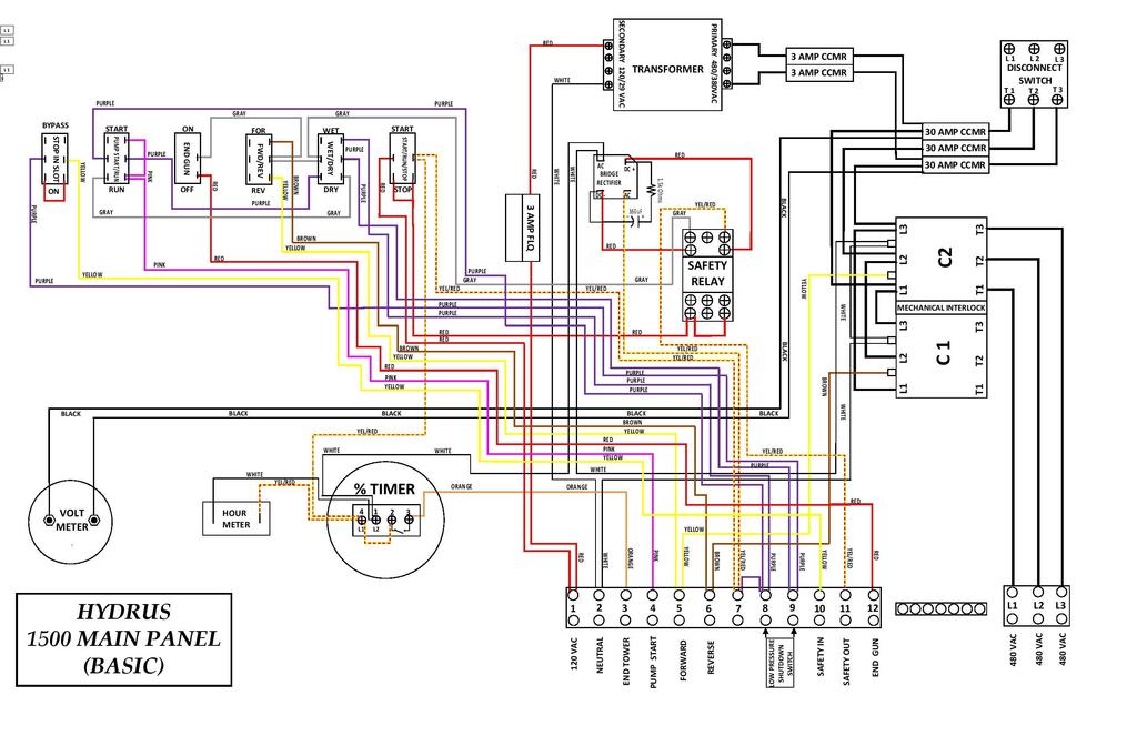
8 Intermediate tower does not run: Main Panel Back Plate 1500 Descriptions and Definitions The components on the back plate consist primarily of the following: 1. Main Disconnect 2. Fuses: Branch Circuit, 500VAC, 30 amp, Type CC 3. Reversing Contactor with Mechanical Interlock 4. Control Transformer,.5KVA 5. Fuses: Transformer Primary, 500VAC, 3 amp, Type CC 6. Fuse: Transformer Secondary, 120VAC, 3 amp, Type FLQ 7. Relay, 120 VDC (12VDC Lockwood Optional) 8. Bridge rectifier, safety delay circuit 9. Terminal Strip 10. Ground lug and Ground Blocks CAUTION! It is important to the safety of the operator and maintenance personnel that all equipment is grounded correctly. DO NOT connect incoming power wires to the main disconnect switch in the main panel until the entire system has been erected, fully wired, checked and grounded Panel Safety Set Up 11 Wire Pivot Safety System: For this configuration with a dedicated outgoing 120 VAC wire, connect to terminal #11 for outgoing safety voltage and terminal #10 for safety voltage back to the panel. 10 Wire Pivot Safety System: For this configuration, connect incoming safety voltage from the end tower relay to terminal block #10. Lockwood Safety System: If you are installing this panel on a Lockwood pivot with the 16VAC safety circuit, you can order P/N: 3611(Lockwood Safety Conversion) at the time of purchase or as a kit for field installation. If you order at time of purchase, the Lockwood safety in circuit connects to terminal block #10. If you are installing in the field, the kit includes all components and instructions to make it easy installation in the field. Alignment linkage is faulty or binding. Check to make sure that the alignment linkage is working properly and activating the run micro switch correctly. If the micro switch is not being activated at all or at the incorrect position, repair and adjust the assembly as required. Forward/ reverse circuit faulty. Verify that the voltage is available by checking for 120 VAC between terminals #5 & #2 for forward and terminals #6 & #2 for reverse. If voltage is not present, check span cable or previous tower panel for fault. Tower run switch is defective. If voltage is present, check to see if the tower contactor is energizing. If the contactor is not pulling in when the run micro switch is operated, check for voltage on the contactor coil wire that is connected to COM of the micro switch. If the voltage is not present, check for loose connections. With the power turned OFF, check continuity on the run micro switch while manually operating the switch. If you do not read continuity between COM and NC while the switch is normal or between COM and NO while the switch is depressed, replace the micro switch. Contactor defective. If voltage is present on the contactor coil wire that is connected to COM of the run micro switch, and the contactor is not pulling in, check the ohm reading of the coil and make sure that the contactor moves freely. The coil should ohm out at approximately 75 to 200 ohms. If the coil has a high reading or is open, replace the contactor. Motor has overheated or is defective. With the system running, check for 480 volts between each phase on the incoming side of the contactor. If the voltage is present, turn the power OFF and ohm the leads to the motor. The leads on the motor side of the contactor should read approximately 10 to 12 ohms between each phase. Check all three phases. Check each leg to ground for continuity. There should be no continuity to ground. If either of these checks fails, check the motor leads again in the junction box on the side of the motor. If any leg shows continuity to ground, or any phase has a zero or high ohm reading, replace the motor. CAUTION! This machine utilizes 480 volts AC power and may cause fatal shock if improperly handled. The main disconnect switch must be in the OFF position and locked to prevent accidental start up. Before attempting to check the 480 volt circuit for faults, it is recommended that the power source voltage be disconnected as well. Use the proper care when checking voltage on any live circuit. Failure to follow these safety precautions may cause a fatal shock. Intermediate tower runs continuously: Alignment linkage faulty or binding. Check to make sure that the alignment linkage is working properly and activating the run micro switch correctly. If the micro switch is not being activated at all or at the incorrect position, repair and adjust the assembly as required. Tower run switch is defective. The run micro switch may not be operating correctly to disconnect the voltage from the contactor coil when the switch is activated. With the power turned OFF, check the run micro switch as indicated in the previous section and replace if needed. Contactor Fault. If voltage is not present on the contactor coil, check to see if the contactor is stuck in the closed position. Replace if necessary. 6 15
9 End tower does not move: Reversing contactor not functioning. With the system control switch in the START position, select FORWARD or REVERSE alternately, insuring that you can hear and see the mechanical operation of the contactors. If the contactors fail to operate correctly, measure for 120 VAC between terminals #5 and #2 in forward and terminals #6 and #2 in reverse. Absence of the voltage would indicate a defective forward-reverse switch. If the contactors are energizing, check the voltage between each phase on the outgoing wires, each phase should read approximately 460 to 480 VAC. If voltage is not present on any leg on the output side, and is present on the input side, replace the contactor. Percentage time defective. With the percentage timer set to 100% and the system started, monitor the percentage timer light. If the light is not on, check the voltage between terminals #3 and #2, it should be approximately 120 VAC. If the voltage is not present, check for bad connections or replace the percentage timer. If voltage is present, turn the percentage timer to 50% and make sure the voltage is intermittent. End tower circuit fault. If voltage is present on terminal #3, leave system running and percentage timer set at 100%. Go to the end tower and check for 120 VAC on the contactor coil. If voltage is not present, check the wires in each tower panel by starting at the middle tower. If voltage is present on the end tower wire, check toward the end, if not, check toward the pivot. End tower contactor defective. If the voltage is present on the contactor coil, check to see if the contactor is energizing. If not, turn the power off and check the coil of the end tower contactor. Remove at least one wire from the coil to insure a proper reading. The coil should ohm out at approximately 75 to 200 ohms. If the coil has a higher reading or is open, replace the contactor. End tower motor failure. If the contactor is energizing, turn the power off and check end tower motor. The leads on the motor side of the contactor should read approximately 10 to 12 ohms between each phase. Check all three phases. Check each leg to ground for continuity. There should be no continuity to ground. If either of these checks fails, check the motor leads again in the junction box on the side of the motor. If any leg shows continuity to ground, or any phase has a zero or high ohm reading, replace the motor. NOTE: HYDRUS strongly recommends the use of Lightning Arrestors. Provisions are made for mounting in the bottom of the main control panel. We also recommend that Lightning Arrestors be installed at the pump panel and the service entrance disconnect. Intermediate Tower Panel The components in the intermediate tower panel consist primarily of the following: 1. Base and Cover 2. Terminal Block Assembly 3. Disconnect Switch 4. Motor Contactor 5. Run and Safety Micro switches 6. Cam and Shaft Assembly 7. Ground Bar All incoming and outgoing span cables connect to the terminal block with the exception of the green or bare ground conductor and the small drain wire which is located under the metallic shield in the span cable. Both incoming and outgoing ground conductors and drain wires should be securely connected to the ground bar. It is very important during the mounting of the tower panels to the machine that the ground wire (#10 green) with ring lug be attached to one of the mounting bolts that bonds to the machine. This is necessary to provide the grounding required by the National Electrical Code as well as validating warranty claims. CAUTION! During initial installation or any maintenance and repair where the cover must be removed, the tower panel disconnect switch should be placed in the OFF position. After replacement of the cover and before leaving the tower, it is important to remember to return the disconnect switch to the ON position, or the system will not operate without bypassing the safety and that tower will not move. End tower drive train fault. If the motor checks out good, check drive train gearboxes or couplings for any faults. End tower runs continuously: Percentage timer fault. With the percentage timer set at 50% and the outgoing wire disconnected, check the voltage on terminal #3. If the voltage is not intermittent and is present constantly, replace the percentage timer. End tower contactor fault. If the voltage is intermittent on terminal #3, replace the outgoing wire and go to the end of the tower. Check the voltage on the contactor coil of the end tower panel. If the voltage is intermittent, check to see if the end tower contactor is stuck in the closed position. End tower circuit fault. If the voltage is not intermittent and is constant on the contactor coil, check the end tower control circuit wires in each tower panel for a short circuit any wire that has 120 VAC present constantly such as the forward or reverse circuit of safety circuit. 14 The spring mounted on the cam is not intended to take slack out of the linkage assembly. Its purpose is to provide a safety shut down in case of a linkage breakage. In this case, the spring drives the cam to open the safety micro switch which shuts the system down. Stall Tower Panel Stall tower panels are basically the same as Intermediate Tower Panels except an adjustable timer (0 up to 60 minutes) has been added. The purpose of the timer in the stall tower is to shut down the center pivot after a period of inactivity of the end tower. Where the safety micro-switches monitor problems with any tower between the pivot and the end tower, the stall timer monitors the end tower. If the end tower fails to move far enough during the selected interval to call for the next to the end tower to move, the stall timer will cause a system to shutdown. Contacts on this timer break the safety return circuit upon the time down. The timer is reset by the run micro-switch voltage to the tower contactor coil. End Tower Panel The end tower is the speed control tower of the system as all the other towers line up between the pivot structure and the end tower. The end tower panel therefore does not contain the alignment components of the other towers. The Contactor coil of the end tower receives power from the percentage timer in the main control panel. The tower starts and stops with this voltage. 7
10 Options Low Pressure Shutdown Option P/N: 3602 This option includes an adjustable pressure switch connected into the safety circuit. To make this option active, place the WET/DRY switch to WET and the PUMPSTART/PUMP RUN switch to RUN. The safety circuit is now running through the pressure switch and as long as the pressure is above the setting, the safety circuit is closed. If the pressure drops below the setting, the safety circuit becomes open and the pivot shuts down. Stop In Slot Option This option allows the pivot to stop at a preset position for servicing. The panel comes with a switch prewired to attach wires from a limit switch mounted at the pivot point. The limit switch is to be wired normally closed for the option to function. When selected to ON, the safety circuit runs through the limit switch and when the limit switch is tripped, the safety is opened and the pivot stops. Center pivot shuts down after system control switch is released from the START position: Alignment shutdown. With the system control switch in the START position, check the 120 volts AC return to terminal #10. If no voltage is present, a tower could be out of alignment causing a safety micro switch to open the safety circuit loop. If the tower can visually be identified, the cause for the tower shutdown must then be determined and corrected before realigning the system. When realigning the system, do not walk the system in the same direction that the alignment shutdown occurred. Change the direction so that the end tower moves in the direction to restore the system to a straight line. CAUTION! In attempting to correct the system alignment error by walking the system in the same direction as the shutdown occurred, compression of the spans truss assemblies may occur and cause structural damage. If a tower cannot be identified visually, it can be isolated by checking the safety circuit loop. To do this, remove the incoming wire from terminal #10 and insert into the ground bar. Go to the middle tower of the system and remove the safety wire from the safety micro switch. Check for continually to ground of each half of the safety loop. The open in the safety loop will be in the direction that does not show continuity to the ground. Reconnect the safety wire and continue the process of splitting the number of towers until the fault is isolated. Be sure to reconnect all wires to the proper positions after the test. Stall timer shutdown. If the open in the safety loop does not appear in any of the safety micro switches, the fault could be in the stall timer located in the next to the end tower. This timer has a contact that opens when the next to the end tower fails to receive a signal to move in the time set on the timer. In the initial test of the above step, if there is no voltage present on terminal #10, change the direction of the system and attempt to start. This will reset the stall timer if it is functional, indicating that there is a problem with the end tower. To test the stall timer, recheck for continuity between terminal #3 & #4, #6 & #7 and #8 & #9 on the timer after removing the jumper wire from terminal #3 & #6. If this does not open, make sure that 120 VAC is being applied to terminal 1 of the timer. This could reset the timer. If this does not regain continuity between #3 & #4, #6 & #7 and #8 & #9, replace the timer. Optional kill functions shutdown. If 120 VAC is present on terminal 10 in the initial test, check for 120 VAC on terminal 7. If not present, this would indicate a loose jumper in the terminals #7 & #8, a bad connection in either the WET/DRY or pump START/RUN switch or a fault in any options installed between terminals 7 thru 10. Safety delay circuit faults. If voltage is present on terminal #10, check to see if the safety relay is energizing. If the relay does not move, check for 110 volts DC on terminals A and B of the relay socket. If 110 VDC is present, replace the relay. If 110 VDC is not present, replace the bridge rectifier or the time delay circuit. 8 13
11 Troubleshooting Procedures Electromechanical Start-Up Procedure CAUTION! Electrical troubleshooting should be only performed by a qualified electrician. This machine utilizes 480 volts AC power and may cause fatal electrical shock if improperly handled. Center pivot completely inoperable: No three phase power. Check for 480 volts at the top side of the main disconnect switch. If there is no power at the top side of the main disconnect switch, check the voltage at the power source. If the voltage exists at the power source, the fault is between the power source and the main disconnect switch. Main disconnect fuse(s) blown. If voltage is present at the top of the main disconnect switch, check the voltage at the bottom of the main disconnect switch, with the main disconnect switch turned on. If the voltage is not present, the fault is with the main disconnect switch. Replace the main disconnect switch. If voltage is present at the bottom of the main disconnect switch, check for voltage at the point where the fuses connect to the contactor. If no voltage is present on any of the three fuses, disconnect the power source as well as placing the disconnect switch in the OFF position. Test for continuity of each fuse before replacing. WARNING! The main disconnect switch must be in the OFF position before attempting to remove any fuse. It is recommended that the power source voltage be disconnected as well. Use a proper fuse pulling tool to remove fuses. Failure to follow these safety precautions may cause fatal electrical shock. 3 amp fuse(s) blown. If voltage is present at the bottom of the main disconnect switch, check for 480 volts between H1 and H2 on the control transformer. If no voltage is present, one or both of the 3 amp fuses are blown. Control transformer defective. If 480 volts exists between H1 and H2 of the control transformer, check voltage between X1 and X2 of the control transformer. If the secondary voltage is less than 100 volts, replace the transformer. 3 amp control fuse blown. If there is a good voltage reading between X1 and X2 of the control transformer, check for 120 volts AC on terminal #1. If there is no voltage present on terminal #1, the 3 amp control fuse is blown. With the main disconnect in the OFF position, check for continuity of the three amp control fuse. If the three amp control fuse is blown, a fault may exist due to a short or overloading of control power circuit. SART/RUN/STOP switch defective. If 120 volts AC exists on terminal #1; with the switch held in the START position, check for 120 volts AC on terminal #7. If voltage is not present on terminal #14 with the switch held in the START position, the fault is either in the switch or a bad connection. CAUTION! Holding the system control switch in the START position overrides all safety shutdown circuit switches in the tower panels. Using this switch, if not carefully monitored, could cause structural damage to the system. 12 WARNING! Be sure that the system has been properly grounded before any application of power. CAUTION! Before starting the system, check the field for any obstructions such as vehicles, tractors, farm equipment, or any obstruction that may cause structural damage to the system, or items that may be damaged by the system. Typical Start up Sequence for Commercial Power Before attempting to start the system, the operator should check the incoming voltage. Verify 480 VAC is available on all three phases with a voltmeter. If a voltmeter is not available, these are done simply by monitoring the panel voltmeter. The voltmeter is connected to L1 and L3. The control transformer is connected to L1 and L3. If the voltmeter reads 480 VAC you should have control power and be ready to start the pivot. Place the FORWARD/ REVERSE Switch in the desired position. Set the Percentage Timer to the desired application rate. Place the Pump switch in the START position, when the pivot is pressured up switch this over to the RUN position. Place the WET/DRY switch in the WET position if starting a pump and DRY if not. Press the Start/Run/Stop switch to the START position, hold for 1second and release. After the system is running, place the pump panel switch to the AUTO position. Typical Start up Sequence for Engine Driven Generator Verify disconnect switch in the pivot panel is in the OFF position. Place the Engine Pump switch in the START/DRY position. Make all safety checks of the engine fluids and shutdown systems. Start the engine. Engage pump clutch. When water has reached the end of the system and all air has been discharged from the pipes, bring the engine speed up and set for and output voltage of 480 VAC. CAUTION! Voltage in excess of 510 VAC may damage pivot panel, tower panels and motors. Before attempting to start the system, the operator should check the incoming voltage. Verify 480 VAC is available on all three phases with a voltmeter. If a voltmeter is not available, this is done simply by monitoring the panel voltmeter and the Control Power Light. The voltmeter is connected to L1 and L3. The control transformer is connected to L1 and L3. If the voltmeter reads 480 VAC and the Control Power Light is on, this verifies power on all three legs. T urn the disconnect switch to the ON position. Place the FORWARD/REVERSE switch in the desired position. Set the Percentage Timer to the desired application rate. Set the WET/DRY switch in the WET position. Press the Start/Run/Stop switch to the START position, hold for 1 second and release. 9
12 10 11
SPC-PANEL Simplex, Single Phase Pump Control Panel
 Pump Installation and Service Manual SPC-PANEL Simplex, Single Phase Pump Control Panel Pump Controls for 2 HP Grinder Pumps NOTE! To the installer: Please make sure you provide this manual to the owner
Pump Installation and Service Manual HRS Hydromatic Retractable System
 Pump Installation and Service Manual HRS Hydromatic Retractable System NOTE! To the installer: Please make sure you provide this manual to the owner of the pumping equipment or to the responsible party
TOTALIZER-TRANSMITTER
 TOTALIZER-TRANSMITTER MODEL TR04-2 OPERATION AND MAINTENANCE MANUAL PARTS LIST FEATURING: *SEALED HOUSING *STANDARD TOTALIZER ASSEMBLY *MAGNETICALLY ACTUATED REED SWITCH 3255 WEST STETSON AVENUE HEMET,
IV. PROOF OF PURCHASE: A warranty claim must be accompanied by proof of the date of purchase.
 PD9100 / 9200 SERIES POWER CONVERTER OWNERS MANUAL PROGRESSIVE DYNAMICS, INC. POWER CONVERTER LIMITED WARRANTY I. LIMITED WARRANTY: Progressive Dynamics, Inc. warrants its power converter to be free from
ARC 1850 LIST OF FIGURES
 PAGE 1.0 INTRODUCTION... 1 2.0 WARRANTY... 1 3.0 UNPACKING YOUR UNIT... 1 4.0 SUGGESTED SAFETY PRECAUTIONS...... 1 4.1 PERSONAL SAFETY PRECAUTIONS. 1 4.2 POWER SUPPLY SAFETY PRECAUTIONS.. 2 5.0 GENERAL
CBC-802 Plug-In Clutch/Brake Control with Solid State Switching
 DIST. AUTORIZADO Plug-In Clutch/Brake Control with Solid State Switching P-29-5 19-0409 Service & Installation Instructions An Altra Industrial Motion Company DIST. AUTORIZADO Brake (Red) and clutch (Green)
331-SV. User Manual THREE PHASE DUPLEX LIFT STATION CONTROL PANEL WITH STATIONVIEW CONTROLLER. Ashland, OH
 331-SV User Manual THREE PHASE DUPLEX LIFT STATION CONTROL PANEL WITH STATIONVIEW CONTROLLER Ashland, OH 800-363-5842 WWW.PRIMEXCONTROLS.COM Warranty void if panel is modified. Call factory with servicing
Model NTX7 Series Automatic Battery Charger User s Manual Rev. 1.0 October 17, 2006
 B R A N D Model NTX7 Series Automatic Battery Charger User s Manual Rev. 1.0 October 17, 2006 For Sales, Support and Service phone: 407-331-4793 fax: 407-331-4708 website: www.xenotronix.com email: information@xenotronix.com
TALCO FIRE SYSTEMS. LSF Start-Up Instructions. 1) IMPORTANT: Inspect the unit for damage. Report any damage to the freight carrier immediately.
 IMPORTANT: Inspect the unit for damage. Report any damage to the freight carrier immediately.") LSF Start-Up Instructions 1) IMPORTANT: Inspect the unit for damage. Report any damage to the freight carrier immediately. 2) PRE-START-UP: Be sure there is water in the pump. Bleed air at all high points
LSF Start-Up Instructions 1) IMPORTANT: Inspect the unit for damage. Report any damage to the freight carrier immediately. 2) PRE-START-UP: Be sure there is water in the pump. Bleed air at all high points
CBC-300 Series & CBC-300C Series Dual Channel Adjust Clutch/Brake Controls
 CBC-300 Series & CBC-300C Series Dual Channel Adjust Clutch/Brake Controls P-269-89-0408 Installation Installation & Operating Instructions Contents Introduction........................... 2 Specifications.........................
CBC-802 Plug-In Clutch/Brake Control with Solid State Switching
 CBC-02 Plug-In Clutch/Brake Control with Solid State Switching P-2104-WE 19-054 Service & Installation Instructions An Altra Industrial Motion Company Brake (Red) and clutch (Green) indicator lights When
StormPro BA Series Sump Pump
 Page 1 of 8 Marks & Meanings DANGER: Keep the pump equipment out of the reach of children! Warns that the failure to follow the directions given could cause serious risk to individuals or objects. WARNING:
User Manual. T6 Tachometer. Online: Telephone: P.O. Box St. Petersburg, Florida 33736
 User Manual T6 Tachometer Online: www.phareselectronics.com Telephone: 727-623-0894 P.O. Box 67251 St. Petersburg, Florida 33736 Table of Contents Overview... 1 Description... 1 Wiring... 1 T6 Tachometer
E7000 AND E7500 INSTALLATION, OPERATION AND MAINTENANCE MANUAL FOR. 4 TO 20 ma ANALOG TRANSMITTERS
 INSTALLATION, OPERATION AND MAINTENANCE MANUAL FOR E7000 AND E7500 4 TO 20 ma ANALOG TRANSMITTERS 3255 W. STETSON AVENUE HEMET, CA 92545-7799 Tel (909) 652-6811 Fax (909) 652-3078 e-mail: info@mccrometer.com
INSPECTOR LINE LOAD SIMULATOR INSTRUCTION MANUAL TASCO, INC.
 INSPECTOR LINE LOAD SIMULATOR INSTRUCTION MANUAL INS120P TASCO, INC. THIS TESTER IS DESIGNED FOR USE ONLY BY QUALIFIED ELECTRICIANS. IMPORTANT SAFETY WARNINGS mwarning Read and understand this material
GC-1. Roof and Gutter De-Icing Control Installation and Operating Instructions FOR EXTERIOR INSTALLATION ONLY
 GC-1 Roof and Gutter De-Icing Control Installation and Operating Instructions FOR EXTERIOR INSTALLATION ONLY GENERAL INFORMATION The GC-1 heating cable controller has been designed and manufactured for
BOLT-ON AND WELD-ON FLUSH FLOOR SLIDEOUT SYSTEMS OPERATION AND SERVICE MANUAL
 BOLT-ON AND WELD-ON FLUSH FLOOR SLIDEOUT SYSTEMS OPERATION AND SERVICE MANUAL TABLE OF CONTENTS SYSTEM...... Warning........ Description...... Prior to Operation OPERATION... Main Components... Mechanical...
II DISTRIBUTION & SUBSTATION TYPE C
 CapCheckIII DISTRIBUTION & SUBSTATION TYPE Ca p a c i t o r C h e c ke r Operating & Instruction Manual 1475 Lakeside Drive Waukegan, Illinois 60085 U.S.A. 847.473.4980 f a x 8 4 7. 4 7 3. 4 9 8 1 w e
Graham. Vari Speed S1000 Instruction Manual. TRANSMISSIONS, Inc. Installation, Operation and Maintenance Manual
 Graham TRANSMISSIONS, Inc. Installation, Operation and Maintenance Manual Vari Speed S1000 Instruction Manual TABLE OF CONTENTS Introduction 4 Unit Features 5 Operating Conditions 6 Specifications 7 Ratings
INSTRUCTION BOOK FOR. Cosmopolitan Electrol For Sizes Up To 9' x 12'
 INSTRUCTION BOOK FOR Cosmopolitan Electrol For Sizes To 9' x 12' Important Safety Instructions When using your video equipment, basic safety precautions should always be followed, including the following:
CRD610 Automatic Fitting Inserter
 CRD610 Automatic Fitting Inserter OPERATIONS MANUAL VERSION 1.2 LAST EDITED 12.12.2018 cleanroomdevices.com 1 Table of Contents Title Page. 1 Table of Contents...2 1.0 General Product & Safety Information....3
AD-7 THERMAL INDICATING AMMETER
 AD-7 THERMAL INDICATING AMMETER a nd ACCESSORIES Operating & Instruction Manual HD ELECTRIC COMPANY 1 4 7 5 L A K E S I D E D R I V E W A U K E G A N, I L L I N O I S 6 0 0 8 5 U. S. A. P H O N E 8 4 7.
ELECTRONIC FIREPLACE DAMPER
 ELECTRONIC FIREPLACE DAMPER Model: FSE Low Profile Series The Flue Sentinel Electronic Fireplace Damper is designed to increase the comfort and energy efficiency of residential homes with gas-fired fireplaces.
TROUBLESHOOTING GUIDE FOR HEAT PUMP BOOSTERS MODELS: HPB11, HPB15, & HPB22
 V3 TROUBLESHOOTING GUIDE FOR HEAT PUMP BOOSTERS MODELS: HPB11, HPB15, & HPB22 PREFACE This guide contains instructions for troubleshooting the Steffes Corporation room heating units: Models HPB 11, HPB
VTC610 Series Voltage Converter. Installation & Operation Manual
 VTC610 Series Voltage Converter Installation & Operation Manual IMPORTANT SAFETY INSTRUCTIONS 1) SAVE THESE INSTRUCTIONS This manual contains important safety and operating instructions for this voltage
ELECTROMAGNETIC FLOWMETERS INSTALLATION, OPERATION AND MAINTENANCE MANUAL
 ELECTROMAGNETIC FLOWMETERS INSTALLATION, OPERATION AND MAINTENANCE MANUAL 30119-03 Rev. 4.8 April, 2013 TABLE OF CONTENTS Section Page 1. INTRODUCTION...1 1.1 Description...1 1.2 Uncrating...1 1.3 Serial
VTC1000 Series Voltage Converter. Installation & Operation Manual
 VTC1000 Series Voltage Converter Installation & Operation Manual INTRODUCTION All new Current Mode switching design offers increased power and reliability in a compact package. Extra input and output filtering
Matrix AP 400V 690V INSTALLATION GUIDE. Quick Reference. ❶ How to Install Pages 6 20 ❷ Startup/Troubleshooting Pages WARNING
 Matrix AP 400V 690V INSTALLATION GUIDE FORM: MAP-IG-E REL. May 2017 REV. 002 2017 MTE Corporation WARNING High Voltage! Only a qualified electrician can carry out the electrical installation of this filter.
Continuing Education Course #206 Introduction to Designing Machine Control Systems Part 2
 1 of 5 Continuing Education Course #206 Introduction to Designing Machine Control Systems Part 2 1. Continuing to answer the following questions indicates that you understands that the presented material
CBC-300 & CBC Series Dual Channel Adjust Clutch/Brake Controls
 CBC-300 & CBC-300- Series Dual Channel Adjust Clutch/Brake Controls P-205-WE 89-0549 Installation & Operating Instructions An Altra Industrial Motion Company Contents Introduction... 2 Specifications...
INSTRUCTIONS FOR THE RELIANCE CONTROLS ARM SERIES AUTOMATIC TRANSFER SWITCH
 INSTRUCTIONS FOR THE RELIANCE CONTROLS ARM SERIES AUTOMATIC TRANSFER SWITCH THE RELIANCE CONTROLS ARM SERIES AUTOMATIC TRANSFER SWITCH IS NOT FOR "DO-IT-YOURSELF" INSTALLATION. It must be installed by
Matrix APAX. 380V-415V 50Hz TECHNICAL REFERENCE MANUAL
 Matrix APAX 380V-415V 50Hz TECHNICAL REFERENCE MANUAL WARNING High Voltage! Only a qualified electrician can carry out the electrical installation of this filter. Quick Reference ❶ Performance Data Pages
The Da-Lite Difference.
 The Da-Lite Difference. Instruction Book for Cosmopolitan Electrol For Sizes Up To 9'x12' DA-LITE SCREEN COMPANY, INC. 3100 North Detroit Street Post Office Box 137 Warsaw, Indiana 46581-0137 Phone: 574-267-8101
Model HPX60 Series Automatic Battery Charger User s Manual Rev. 1.0 October 17, 2006
 B R A N D Model HPX60 Series Automatic Battery Charger User s Manual Rev. 1.0 October 17, 2006 For Sales, Support and Service phone: 407-331-4793 fax: 407-331-4708 website: www.xenotronix.com email: information@xenotronix.com
2015 EDITION SUBMERSIBLE MOTORS AIM MANUAL. APPLICATION INSTALLATION MAINTENANCE 60 Hz, Single-Phase and Three-Phase Motors. franklinwater.
 0 EDITION AIM MANUAL SUBMERSIBLE MORS APPLICATION INSTALLATION 60 Hz, Single-Phase and Three-Phase Motors franklinwater.com All Motors System Troubleshooting Motor Does Not Start A. No power or incorrect
Linear Actuator Swing Gate Operator Installation Manual Model # LA405-24
 Linear Actuator Swing Gate Operator Installation Manual Model # LA405-24 2 Contents Contents Product Information and Specs. 3 Mechanical 3 Electrical, Line Connections 3 Electrical, Control Connections
Flow Measurement Solutions for Water & Waste Water INSTALLATION OPERATION & MAINTENANCE MANUAL
 Flow Measurement Solutions for Water & Waste Water INSTALLATION OPERATION & MAINTENANCE MANUAL Table of Contents SECTION 1 - INTRODUCTION Specifications... 2 Dimensions... 2 Flow Ranges... 2 SECTION 2
CIVACON GROUND VERIFICATION RACK MONITOR SYSTEM and ASSOCIATED EQUIPMENT
 GROUND VERIFICATION RACK MONITOR SYSTEM and ASSOCIATED EQUIPMENT INSTALLATION AND WIRING INSTRUCTIONS MANUAL 8030 MANUAL PART NUMBER JANUARY 2011. 4304 MATTOX RD. KANSAS CITY, MO 64150 TABLE OF CONTENTS
INSTRUCTIONS FOR THE RELIANCE Fast/Tran TM ARL0909 & ARL0909R
 INSTRUCTIONS FOR THE RELIANCE Fast/Tran TM ARL0909 & ARL0909R THE RELIANCE Fast/Tran IS NOT FOR "DO-IT-YOURSELF" INSTALLATION. It must be installed by a qualified electrician thoroughly familiar with all
WF-5110R True Sine Wave Inverter
 Operator s Manual WF-5110R True Sine Wave Inverter WF-9900 Series WF-5110R ( The Inverter model number is located on the label on top of the enclosure) Distributed in the U.S.A. and Canada by ARTERRA DISTRIBUTION
A WORD ABOUT PROPER GROUNDING
 A Word About Proper Grounding Section 5-3 A WORD ABOUT PROPER GROUNDING Due to the wet environment of irrigation equipment, it is very important that your Pierce CP600 Center Pivot Irrigation System be
CLEAN ROOM DEVICES, LLC "WHERE TUBING AND FITTINGS COME TOGETHER"
 CLEAN ROOM DEVICES, LLC "WHERE TUBING AND FITTINGS COME TOGETHER" CRD600AF Automatic Fitting Inserter With Auto Feed OPERATIONS MANUAL (Shown with optional alcohol dispenser) 1 VERSION 1.1 LAST EDITED
Adjustable Angled Incline Conveyor Owners Manual with Operating Instructions
 Adjustable Angled Incline Conveyor Owners Manual with Operating Instructions Revision 012211 Table of Contents Basic Conveyor Features 3 Getting Started 4 Setting Up the Incline Conveyor 5 Belt Removal
Electronically Commutated Motors
 Electronically Commutated Motors INSTALLATION, OPERATION & MAINTENANCE MANUAL IM-4055 September 2016 Throughout this manual, there are a number of HAZARD WARNINGS that must be read and adhered to in order
WF-5100 Series True Sine Wave Inverters
 Operator s Manual WF-5100 Series True Sine Wave Inverters WF-9900 Series WF-5118 WF-5120 ( The Inverter model number is located on the label on top of the enclosure) Distributed in the U.S.A. and Canada
DC-AC Power Inverter SAM Manual. Please read this manual before installing your inverter
 DC-AC Power Inverter SAM-100-12 Owner's Manual Please read this manual before installing your inverter WARNINGS TO REDUCE THE RISK OF FIRE, ELECTRIC SHOCK, EXPLOSION OR INJURY 1. Do not connect to AC distribution
Installation and Operation Instructions Safety Director Arrow
 Installation and Operation Instructions Safety Director Arrow! WARNING! Failure to install or use this product according to manufacturers recommendations may result in property damage, serious bodily/personal
REFERENCE MANUAL FORM: MX-TRM-E REL REV MTE
 Matrix APAX 380V-415V 50Hz TECHNICAL REFERENCE MANUAL FORM: MX-TRM-E REL. September 2014 REV. 002 2014 MTE Corporation WARNING High Voltage! Only a qualified electrician can carry out the electrical installation
CRD600 Automatic Fitting Inserter
 CRD600 Automatic Fitting Inserter OPERATIONS MANUAL VERSION 2.3 LAST EDITED 12.07.2018 cleanroomdevices.com 1 Table of Contents Title Page.. 1 Table of Contents. 2 1.0 General Product & Safety Information...3
The Da-Lite Difference.
 The Da-Lite Difference. Instruction Book for LARGE CoSMOPOLITAN Electrol DA-LITE SCREEN COMPANY LLC 3100 North Detroit Street Post Office Box 137 Warsaw, IN 46581-0137 USA P 800-622-3737 / 574-267-8101
CLEAN ROOM DEVICES, LLC "WHERE TUBING AND FITTINGS COME TOGETHER"
 CLEAN ROOM DEVICES, LLC "WHERE TUBING AND FITTINGS COME TOGETHER" CRD600 Automatic Fitting Inserter OPERATIONS MANUAL VERSION 2.1 LAST EDITED 7.25.14 DOCUMENT NUMBER 001 cleanroomdevices.com 1 Table of
4" ENVIRONMENTAL E-SERIES PUMPS OWNER'S MANUAL. DANGER warns about hazards that will cause. WARNING warns about hazards that can cause
 4" ENVIRONMENTAL E-SERIES PUMPS OWNER'S MANUAL BEFORE INSTALLING PUMP, BE SURE TO READ THIS OWNER S MANUAL CAREFULLY. CAUTION Fill pump with water before starting or pump will be damaged. The motor on
ichards MANUFACTURING COMPANY, SALES, INC. 517 LYONS AVENUE, IRVINGTON, NJ Phone Fax
 Network Protector Instruction Manual Type 316NP ichards MANUFACTURING COMPANY, SALES, INC. 517 LYONS AVENUE, IRVINGTON, NJ 07111 Phone 973-371-1771 Fax 973-371-9538 IM 1232-001B DISCLAIMER OF WARRANTIES
Dimensions 12/800N 12/1200N D. DC to AC Power Inverters. OWNERS MANUAL for Models: OWNERS MANUAL April ISO 9001:2000 Certified Company
 Manufacturer of Dimensions Inverters 4467 White Bear Parkway St. Paul, MN 55110 Phone: 651-653-7000 Fax: 651-653-7600 E-mail: inverterinfo@sensata.com Web: www.dimensions.sensata.com OWNERS MANUAL April
DC to DC Step Up Converter Model: VTC305
 DC to DC Step Up Converter Model: VTC305 Owner's Manual Please read this manual before operating your converter INTRODUCTION Step up a 12 VDC battery to between 13.5 and 17.0 or 24.0 and 27.5 VDC in 0.5
Embedded Rack Slide-out System
 Embedded Rack Slide-out System SERVICE MANUAL Rev: 02.16.2017 Page 1 Electric Embedded Rack Slide-out System TABLE OF CONTENTS Safety Information 3 Product Information 3 Operation 4 Extending Slide-Out
The Da-Lite Difference.
 The Da-Lite Difference. Instruction Book for Large Advantage Electrol DA-LITE SCREEN COMPANY, INC. 3100 North Detroit Street Post Office Box 137 Warsaw, Indiana 46581-0137 Phone: 574-267-8101 800-622-3737
Manual Transfer Switch
 Manual Transfer Switch Instruction Manual 30 1200 Amp 2, 3 & 4 Pole Page 1 WARNING Before Installation READ THIS MANUAL carefully to learn how to properly install, operate and maintain this unit. Personal
Installation & Operation Manual PWS1000R Rack Mount Power Supply
 Installation & Operation Manual PWS1000R Rack Mount Power Supply 8128 River Way, Delta B.C. V4G 1K5 Canada T. 604.946.9981 F. 604.946.9983 TF. 1.800.668.3884 (US/CANADA) www.analyticsystems.com Copyright
Operations Manual. Zero Speed Switch Sensor Model ZS09P
 Zero Speed Switch Sensor Model ZS09P The must be referred to for correct installation. Failure to comply with the shall void all warranties and liabilities. Overview The Phares Electronics Model ZS09P
Cardinal DETECTO. PORTABLE PLATFORM SCALES Digital Type Series 850F Owner s Manual
 Cardinal DETECTO PORTABLE PLATFORM SCALES Digital Type Series 850F Owner s Manual CARDINAL SCALE MFG. CO. PO BOX 151, WEBB CITY, MO 64870 0066-M176-O1 Rev H 10/06 417-673-4631 www.cardinalscale.com Printed
Generator Start Control Module
 Generator Start Control Module Part# GSCM-mini-i ATKINSON ELECTRONICS, INC. 14 West Vine Street Murray, Utah 84107 Contact cbdsales@atkinsonel.com for the proper hookup diagram. Please include the generator
3 Phase Smart Controller
 3 Phase Smart Controller Installation and Owner s Manual STP-SCIII 208-230 VAC, 60Hz, 120 Volt Coil Franklin Fueling 3760 Marsh Rd. Madison WI 53718 USA Tel: +1 608 838 8786 800 225 9787 Fax: +1 608 838
APOLLO Gate Operators, Inc.
 APOLLO Gate Operators, Inc. Model 3500ETL/3600ETL Commercial Swing Gate Operator INSTALLATION MANUAL 01/08 CONTENTS IMPORTANT SAFETY INSTRUCTIONS. 3 Applications... 4 Pre-Installation Checklist... 5 Parts
MARTINDALE MARTINDALE IN2001/IN2003 INSULATION & CONTINUITY TESTERS INSTRUCTION MANUAL IN2001/IN2003 INSULATION & CONTINUITY TESTERS
 MARTINDALE ELECTRIC Martindale Electric Company LTD Metrohm House Penfold Trading Estate Imperial Way Watford Herts WD24 4YY T: 01923 441717 F: 01923 446900 Email: sales@martindale-electric.co.uk web:
3-PHASE SMART CONTROLLER STP-SCIIIC INSTALLATION GUIDE
 3-PHASE SMART CONTROLLER STP-SCIIIC INSTALLATION GUIDE The information in this publication is provided for reference only. While every effort has been made to ensure the reliability and accuracy of the
n Operator s Manual n Redundant Control Unit FOR CFR UNINTERRUPTIBLE POWER SUPPLIES FROM ALPHA TECHNOLOGIES
 n Operator s Manual n Redundant Control Unit FOR CFR UNINTERRUPTIBLE POWER SUPPLIES FROM ALPHA TECHNOLOGIES TABLE OF CONTENTS 1. Introduction...1 1.1 The Alpha Redundant Control Unit (RCU)... 1 1.2 A Tour
Models DP10 & DP20 Series Low Voltage Disconnects User s Manual Rev. 1.1 October 31, 2007
 B R A N D Models DP10 & DP20 Series Low Voltage Disconnects User s Manual Rev. 1.1 October 31, 2007 For Sales, Support and Service phone: 407-331-4793 fax: 407-331-4708 website: www.xenotronix.com email:
715B CONTROL SERIES. Instruction Manual Line Voltage DC Brushless Motor Control CONTROLS. Phone (317) Fax (317)
 Fax (317)") 715B CONTROL SERIES CONTROLS Instruction Manual Line Voltage DC Brushless Motor Control LT715B (IM-715B-0100) P.O. Box 10 5000 W. 106th Street Zionsville, Indiana 46077 Phone (317) 873-5211 Fax (317) 873-1105
715B CONTROL SERIES CONTROLS Instruction Manual Line Voltage DC Brushless Motor Control LT715B (IM-715B-0100) P.O. Box 10 5000 W. 106th Street Zionsville, Indiana 46077 Phone (317) 873-5211 Fax (317) 873-1105
2SHE Series Direct-Drive Shutter Fans
 Operational Instruction and Parts Manual Item #: 481810 Rev Date: 101414 2SHE Series Direct-Drive Shutter Fans Fantech, Inc. and Systemair Mfg. certify that the ventilators shown herein are licensed to
MODEL A96 SERIES. 130Vdc Switchmode Utility Rectifier / Battery Charger. Used with LaMarche Power Cage ECN/DATE
 MODEL A96 SERIES 130Vdc Switchmode Utility Rectifier / Battery Charger Used with LaMarche Power Cage CPN112138 ECN/DATE ISSUE DATE: ECN 17010-12/05 106 BRADROCK DRIVE DES PLAINES, IL. 60018-1967 (847)
OWNERS MANUAL JANUARY 2007 ISO
 Manufacturer of Dimensions TM Inverters 4467 White Bear Parkway St. Paul, MN 55110 Phone: 651-653-7000 Fax: 651-653-7600 E-mail: inverterinfo@sensata.com Web: www.dimensions.sensata.com 121231B OWNERS
Installation and Set Up Instructions
 SL SLIDING GATE MOTOR KIT Solar Powered and 12V Low Voltage Installation and Set Up Instructions Unit 27 / 49 Corporate Boulevard Bayswater Vic 3153 Phone 1800 111 930 Email info@gforceautogates.com.au
LEV/Wn Building A Connected World
 LEV/Wn Building A Connected World PK-93370-10-00-2B Installing and Testing a GFCI Please read this leaflet completely before getting started. A CAUTION To prevent severe shock or electrocution always turn
INSTALLATION & OWNER'S MANUAL
 INSTALLATION & OWNER'S MANUAL THE EAGLE POWER I BATTERY BACK UP PHONE (818) 764-6690 / TOLL FREE (800) 708-8848 PRE INSTALLATION INSTRUCTIONS BEFORE PROCEEDING WITH INSTALLATION READ THIS MANUAL THOROUGHLY
Ezyfit AC Controller INSTRUCTION BOOK 2 & 4 STATION UNITS
 Ezyfit AC Controller INSTRUCTION BOOK 2 & 4 STATION UNITS Features This unit is available in two and four station configurations. Designed for residential applications, this controller has an individual
37SCENE 46SCENE 79SCENE
 Installation and Operation Instructions LED SCENE LIGHT LED SCENE LIGHT 37SCENE 46SCENE 79SCENE 37SCENE 46SCENE Introduction The 37SCENE, 46SCENE, 79SCENE LED Scene Lights are designed for the emergency
NEO-DYN MODEL 100P ENCLOSURE 7 ADJUSTABLE EXPLOSION-PROOF PRESSURE SWITCH
 NEO-DYN MODEL 100P ENCLOSURE 7 ADJUSTABLE EXPLOSION-PROOF PRESSURE SWITCH INSTALLATION AND OPERATION MANUAL PN 610-0006 Rev E WARNING CAUTION SPECIAL CONDITIONS FOR SAFE USE NOTE Manual No. 610-0006 Rev
Generator Start Control Module
 Generator Start Control Module Part# GSCM-mini-o ATKINSON ELECTRONICS, INC. 14 West Vine Street Murray, Utah 84107 Contact cbdsales@atkinsonel.com for the proper hookup diagram. Please include the generator
MIL-24/2600Q MIL-24/3200DQ
 Manufacturer of Dimensions TM Inverters 4467 White Bear Parkway St. Paul, MN 55110 Phone: 651-653-7000 Fax: 651-653-7600 E-mail: inverterinfo@sensata.com Web: www.dimensions.sensata.com 121473B OWNER'S
Instruction Book for. ContouR ElECtRol
 Instruction Book for ContouR ElECtRol IMPORTANT SAFETY INSTRUCTIONS When using your video equipment, basic safety precautions should always be followed, including the following: 1. Read and understand
ITS-50R TRANSFER SWITCH OWNER S MANUAL
 ITS-50R OWNER S MANUAL IOTA Engineering Transfer Switches provide automatic power switching between two or three separate 120/240 volt AC input sources, including powercords, onboard generators, onboard
RK Standby Battery Operator s Manual
 49-8103RK Standby Battery Operator s Manual Part Number: 71-0117RK Revision: 0 Released: 8/18/08 www.rkiinstruments.com Product Warranty RKI Instruments, Inc., warrants gas alarm equipment sold by us to
ADI-125/750 ADI-125/1500 ADI-125/2500
 Manufacturer of Dimensions TM Inverters 4467 White Bear Parkway St. Paul, MN 55110 Phone: 651-653-7000 Fax: 651-653-7600 E-mail: inverterinfo@sensata.com Web: www.dimensions.sensata.com 121094B OWNERS
The Da-Lite Difference.
 The Da-Lite Difference. Instruction Book for tensioned Advantage Electrol DA-LITE SCREEN COMPANY, INC. 3100 North Detroit Street Post Office Box 137 Warsaw, Indiana 46581-0137 Phone: 574-267-8101 800-622-3737
Transfer Switch TS-50. Owner s Manual
 Transfer Switch TS-50 Owner s Manual Table of Contents Introduction 2 Installation 2 Operational Testing 7 Troubleshooting 7 Hi-Pot Testing 8 Generator Note 9 Medical Appliances 10 Caution 10 Disclaimer
TrimSync Race Edition Installation & Operating Instructions
 TrimSync Race Edition Installation & Operating Instructions Mounting the Device The unit should be mounted in a dry area away from sources of heat. Mounting the unit near the trim pumps will reduce wiring
MD10. Engine Controller. Installation and User Manual for the MD10 Engine Controller. Full Version
 MD10 Engine Controller Installation and User Manual for the MD10 Engine Controller. Full Version File: MartinMD10rev1.4.doc May 16, 2002 2 READ MANUAL BEFORE INSTALLING UNIT Receipt of shipment and warranty
OPERATION MANUAL Variable Speed Pump Controller Dated: 06/04/2013 Pump Down Application. Document No.: LMSII_V100_OM Page 1 of 8 Model-V100 LMS II
 Document No.: LMSII_V100_OM Page 1 of 8 LMS II Document No.: LMSII_V100_OM Page 2 of 8 1. Operation: When the wet well level rises above the on level set point, the lead pump will start after an adjustable
The Da-Lite Difference.
 The Da-Lite Difference. Instruction Book for Boardroom Electrol DA-LITE SCREEN COMPANY, INC. 3100 North Detroit Street Post Office Box 137 Warsaw, Indiana 46581-0137 Phone: 574-267-8101 800-622-3737 Fax:
4-20 ELECTRONIC VERTICAL FLOW METERS
 309-2 Rev. 4.6/07-09 4-20 ELECTRONIC VERTICAL FLOW METERS MODELS VF2D, VF30D, and VF32D OPERATION AND MAINTENANCE MANUAL PARTS LIST FEATURING: *MODEL FC0 FLOWCOM REGISTER INDICATOR-TOTALIZER *CERAMIC BEARING
Power. On Your Terms.
 Power. On Your Terms. 10 YEAR LIMITED WARRANTY PHI 1310 TM 1 SIMPLIPHI POWER, INC. REV102016 10 YEAR LIMITED WARRANTY: PHI 1310 TM LIMITED PRO-RATED WARRANTY COVERAGE The SimpliPhi Power PHI 1310 as supplied
INSTALLATION GUIDE. Universal System for Zero Turn Mowers
 INSTALLATION GUIDE Universal System for Zero Turn Mowers Table of Contents General Information 1 Important Notice to Purchaser 2 Specifications 2 Intended Usage 2 Important Information 3 General Safety
Installation and Operation Guide for PD4100 Series Power Control Centers
 Installation and Operation Guide for PD4100 Series Power Control Centers Extended warranties are available for purchase at www.progressivedyn.com Member Thank you for selecting Progressive Dynamics as
MODEL 422 Submersible Pump Controller
 MODEL 422 Submersible Pump Controller Monitors True Motor Power (volts x current x power factor) Detects Motor Overload or Underload Operates on 120 or 240VAC, Single-phase or 3-phase Built-in Trip and
Battery Back-up BBM Owner's Manual. Please read this manual BEFORE installing your inverter
 Battery Back-up BBM-1225 Owner's Manual Please read this manual BEFORE installing your inverter owner's MAnUAL index section 1 Safety Instructions... 3 section 2 Layout and Dimensions... 4 section 3 Description
StormPro BCV400 Sewage Ejector Pump
 Page 1 of 8 Marks & Meanings DANGER: Keep the pump equipment out of the reach of children! Warns that the failure to follow the directions given could cause serious risk to individuals or objects. WARNING:
RK Standby Battery Operator s Manual
 49-8104RK Standby Battery Operator s Manual Part Number: 71-0118RK Revision: C Released: 8/4/17 www.rkiinstruments.com Product Warranty RKI Instruments, Inc. warrants gas alarm equipment sold by us to
www. ElectricalPartManuals. com Instructions for Field Testing of Ground Fault Systems Utilizing Cutler-Hammer Magnum DS Circuit Breakers
 Instructions for Field Testing of Ground Fault Systems Utilizing Cutler-Hammer Magnum DS Circuit Breakers The National Electrical Code makes the following statement regarding ground fault conformance testing:
High Frequency SineWave Guardian TM
 High Frequency SineWave Guardian TM 380V 480V INSTALLATION GUIDE FORM: SHF-IG-E REL. January 2018 REV. 002 2018 MTE Corporation High Voltage! Only a qualified electrician can carry out the electrical installation