NA-5S. Operator s Manual. IM305-C Issue D ate 10-Sep Lincoln Global, Inc. All Rights Reserved.
|
|
|
- Elinor Rogers
- 6 years ago
- Views:
Transcription
1 Operator s Manual NA-5S For use with machines having Code Numbers: 8203; 8204; 8205; 8206; 8207; 8208; 8209; 8400; 8464; 8465; 8466; 8467; 8468; 8469; 8470; 8471; 8472; 8473; 8474; 8475; 8476; 8477; 8547; 8866; 8867; 8868; 8869; 8870; 8871; 8872; 8873; 8874; 8875; 8876; 8877; 8878; 8879; 8880; 8881; 8882; 8883; 8884; 8885; 8993; 9145; 9147; 9338; 9807; 9808; 9809; 10315; Save for future reference Register your machine: Authorized Service and Distributor Locator: Date Purchased Code: (ex: 10859) Serial: (ex: U ) IM305-C Issue D ate 10-Sep Lincoln Global, Inc. All Rights Reserved.
2 THANK YOU FOR SELECTING A QUALITY PRODUCT BY LINCOLN ELEC TRIC. PLEASE EXAMINE CARTON AND EQUIPMENT FOR DAMAGE IMMEDIATELY When this equipment is shipped, title passes to the purchaser upon receipt by the carrier. Consequently, claims for material damaged in shipment must be made by the purchaser against the transportation company at the time the shipment is received. SAFETY DEPENDS ON YOU Lincoln arc welding and cutting equipment is designed and built with safety in mind. However, your overall safety can be increased by proper installation... and thoughtful operation on your part. DO NOT INSTALL, OPERATE OR REPAIR THIS EQUIPMENT WITHOUT READING THIS MANUAL AND THE SAFETY PRECAUTIONS CONTAINED THROUGHOUT. And, most importantly, think before you act and be careful. WARNING This statement appears where the information must be followed exactly to avoid serious personal injury or loss of life. CAUTION This statement appears where the information must be followed to avoid minor personal injury or damage to this equipment. KEEP YOUR HEAD OUT OF THE FUMES. DON T get too close to the arc. Use corrective lenses if necessary to stay a reasonable distance away from the arc. READ and obey the Safety Data Sheet (SDS) and the warning label that appears on all containers of welding materials. USE ENOUGH VENTILATION or exhaust at the arc, or both, to keep the fumes and gases from your breathing zone and the general area. IN A LARGE ROOM OR OUTDOORS, natural ventilation may be adequate if you keep your head out of the fumes (See below). USE NATURAL DRAFTS or fans to keep the fumes away from your face. If you de velop unusual symptoms, see your supervisor. Perhaps the welding atmosphere and ventilation system should be checked. WEAR CORRECT EYE, EAR & BODY PROTECTION PROTECT your eyes and face with welding helmet properly fitted and with proper grade of filter plate (See ANSI Z49.1). PROTECT your body from welding spatter and arc flash with protective clothing including woolen clothing, flame-proof apron and gloves, leather leggings, and high boots. PROTECT others from splatter, flash, and glare with protective screens or barriers. IN SOME AREAS, protection from noise may be appropriate. BE SURE protective equipment is in good condition. Also, wear safety glasses in work area AT ALL TIMES. SPECIAL SITUATIONS DO NOT WELD OR CUT containers or materials which previously had been in contact with hazardous substances unless they are properly cleaned. This is extremely dangerous. DO NOT WELD OR CUT painted or plated parts unless special precautions with ventilation have been taken. They can release highly toxic fumes or gases. Additional precautionary measures PROTECT compressed gas cylinders from excessive heat, mechanical shocks, and arcs; fasten cylinders so they cannot fall. BE SURE cylinders are never grounded or part of an electrical circuit. REMOVE all potential fire hazards from welding area. ALWAYS HAVE FIRE FIGHTING EQUIPMENT READY FOR IMMEDIATE USE AND KNOW HOW TO USE IT. Safety 01 of 04-06/15/2016
3 SAFETY SECTION A: WARNINGS CALIFORNIA PROPOSITION 65 WARNINGS Diesel Engines Diesel engine exhaust and some of its constituents are known to the State of California to cause cancer, birth defects, and other reproductive harm. Gasoline Engines The engine exhaust from this product contains chemicals known to the State of California to cause cancer, birth defects, or other reproductive harm. ARC WELDING CAN BE HAZARDOUS. PROTECT YOURSELF AND OTHERS FROM POSSIBLE SERIOUS INJURY OR DEATH. KEEP CHILDREN AWAY. PACEMAKER WEARERS SHOULD CONSULT WITH THEIR DOCTOR BEFORE OPERATING. Read and understand the following safety highlights. For additional safety information, it is strongly recommended that you purchase a copy of Safety in Welding & Cutting - ANSI Standard Z49.1 from the American Welding Society, P.O. Box , Miami, Florida or CSA Standard W A Free copy of Arc Welding Safety booklet E205 is available from the Lincoln Electric Company, St. Clair Avenue, Cleveland, Ohio BE SURE THAT ALL INSTALLATION, OPERATION, MAINTENANCE AND REPAIR PROCEDURES ARE PERFORMED ONLY BY QUALIFIED INDIVIDUALS. FOR ENGINE POWERED EQUIPMENT. 1.a. Turn the engine off before troubleshooting and maintenance work unless the maintenance work requires it to be running. 1.b. Operate engines in open, well-ventilated areas or vent the engine exhaust fumes outdoors. 1.c. Do not add the fuel near an open flame welding arc or when the engine is running. Stop the engine and allow it to cool before refueling to prevent spilled fuel from vaporizing on contact with hot engine parts and igniting. Do not spill fuel when filling tank. If fuel is spilled, wipe it up and do not start engine until fumes have been eliminated. 1.d. Keep all equipment safety guards, covers and devices in position and in good repair. Keep hands, hair, clothing and tools away from V-belts, gears, fans and all other moving parts when starting, operating or repairing equipment. 1.e. In some cases it may be necessary to remove safety guards to perform required maintenance. Remove guards only when necessary and replace them when the maintenance requiring their removal is complete. Always use the greatest care when working near moving parts. 1.f. Do not put your hands near the engine fan. Do not attempt to override the governor or idler by pushing on the throttle control rods while the engine is running. 1.g. To prevent accidentally starting gasoline engines while turning the engine or welding generator during maintenance work, disconnect the spark plug wires, distributor cap or magneto wire as appropriate. 1.h. To avoid scalding, do not remove the radiator pressure cap when the engine is hot. ELECTRIC AND MAGNETIC FIELDS MAY BE DANGEROUS 2.a. Electric current flowing through any conductor causes localized Electric and Magnetic Fields (EMF). Welding current creates EMF fields around welding cables and welding machines 2.b. EMF fields may interfere with some pacemakers, and welders having a pacemaker should consult their physician before welding. 2.c. Exposure to EMF fields in welding may have other health effects which are now not known. 2.d. All welders should use the following procedures in order to minimize exposure to EMF fields from the welding circuit: 2.d.1. Route the electrode and work cables together - Secure them with tape when possible. 2.d.2. Never coil the electrode lead around your body. 2.d.3. Do not place your body between the electrode and work cables. If the electrode cable is on your right side, the work cable should also be on your right side. 2.d.4. Connect the work cable to the workpiece as close as possible to the area being welded. 2.d.5. Do not work next to welding power source. Safety 02 of 04-06/15/2016
4 SAFETY ELECTRIC SHOCK CAN KILL. 3.a. The electrode and work (or ground) circuits are electrically hot when the welder is on. Do not touch these hot parts with your bare skin or wet clothing. Wear dry, hole-free gloves to insulate hands. 4.a. ARC RAYS CAN BURN. Use a shield with the proper filter and cover plates to protect your eyes from sparks and the rays of the arc when welding or observing open arc welding. Headshield and filter lens should conform to ANSI Z87. I standards. 3.b. Insulate yourself from work and ground using dry insulation. Make certain the insulation is large enough to cover your full area of physical contact with work and ground. In addition to the normal safety precautions, if welding must be performed under electrically hazardous conditions (in damp locations or while wearing wet clothing; on metal structures such as floors, gratings or scaffolds; when in cramped positions such as sitting, kneeling or lying, if there is a high risk of unavoidable or accidental contact with the workpiece or ground) use the following equipment: Semiautomatic DC Constant Voltage (Wire) Welder. DC Manual (Stick) Welder. AC Welder with Reduced Voltage Control. 3.c. In semiautomatic or automatic wire welding, the electrode, electrode reel, welding head, nozzle or semiautomatic welding gun are also electrically hot. 3.d. Always be sure the work cable makes a good electrical connection with the metal being welded. The connection should be as close as possible to the area being welded. 3.e. Ground the work or metal to be welded to a good electrical (earth) ground. 3.f. Maintain the electrode holder, work clamp, welding cable and welding machine in good, safe operating condition. Replace damaged insulation. 3.g. Never dip the electrode in water for cooling. 3.h. Never simultaneously touch electrically hot parts of electrode holders connected to two welders because voltage between the two can be the total of the open circuit voltage of both welders. 3.i. When working above floor level, use a safety belt to protect yourself from a fall should you get a shock. 3.j. Also see It ems 6.c. and 8. 4.b. 4.c. Use suitable clothing made from durable flame-resistant material to protect your skin and that of your helpers from the arc rays. Protect other nearby personnel with suitable, non-flammable screening and/or warn them not to watch the arc nor expose themselves to the arc rays or to hot spatter or metal. FUMES AND GASES CAN BE DANGEROUS. 5.a. Welding may produce fumes and gases hazardous to health. Avoid breathing these fumes and gases. When welding, keep your head out of the fume. Use enough ventilation and/or exhaust at the arc to keep fumes and gases away from the breathing zone. When welding hardfacing (see instructions on container or SDS) or on lead or cadmium plated steel and other metals or coatings which produce highly toxic fumes, keep exposure as low as possible and within applicable OSHA PEL and ACGIH TLV limits using local exhaust or mechanical ventilation unless exposure assessments indicate otherwise. In confined spaces or in some circumstances, outdoors, a respirator may also be required. Additional precautions are also required when welding on galvanized steel. 5. b. The operation of welding fume control equipment is affected by various factors including proper use and positioning of the equipment, maintenance of the equipment and the specific welding procedure and application involved. Worker exposure level should be checked upon installation and periodically thereafter to be certain it is within applicable OSHA PEL and ACGIH TLV limits. 5.c. Do not weld in locations near chlorinated hydrocarbon vapors coming from degreasing, cleaning or spraying operations. The heat and rays of the arc can react with solvent vapors to form phosgene, a highly toxic gas, and other irritating products. 5.d. Shielding gases used for arc welding can displace air and cause injury or death. Always use enough ventilation, especially in confined areas, to insure breathing air is safe. 5.e. Read and understand the manufacturer s instructions for this equipment and the consumables to be used, including the Safety Data Sheet (SDS) and follow your employer s safety practices. SDS forms are available from your welding distributor or from the manufacturer. 5.f. Also see item 1.b. Safety 03 of 04-06/15/2016
5 SAFETY WELDING AND CUTTING SPARKS CAN CAUSE FIRE OR EXPLOSION. 6.a. Remove fire hazards from the welding area. If this is not possible, cover them to prevent the welding sparks from starting a fire. Remember that welding sparks and hot materials from welding can easily go through small cracks and openings to adjacent areas. Avoid welding near hydraulic lines. Have a fire extinguisher readily available. 6.b. Where compressed gases are to be used at the job site, special precautions should be used to prevent hazardous situations. Refer to Safety in Welding and Cutting (ANSI Standard Z49.1) and the operating information for the equipment being used. 6.c. When not welding, make certain no part of the electrode circuit is touching the work or ground. Accidental contact can cause overheating and create a fire hazard. 6.d. Do not heat, cut or weld tanks, drums or containers until the proper steps have been taken to insure that such procedures will not cause flammable or toxic vapors from substances inside. They can cause an explosion even though they have been cleaned. For information, purchase Recommended Safe Practices for the Preparation for Welding and Cutting of Containers and Piping That Have Held Hazardous Substances, AWS F4.1 from the American Welding Society (see address above). 6.e. Vent hollow castings or containers before heating, cutting or welding. They may explode. 6.f. Sparks and spatter are thrown from the welding arc. Wear oil free protective garments such as leather gloves, heavy shirt, cuffless trousers, high shoes and a cap over your hair. Wear ear plugs when welding out of position or in confined places. Always wear safety glasses with side shields when in a welding area. 6.g. Connect the work cable to the work as close to the welding area as practical. Work cables connected to the building framework or other locations away from the welding area increase the possibility of the welding current passing through lifting chains, crane cables or other alternate circuits. This can create fire hazards or overheat lifting chains or cables until they fail. 6.h. Also see item 1.c. CYLINDER MAY EXPLODE IF DAMAGED. 7.a. Use only compressed gas cylinders containing the correct shielding gas for the process used and properly operating regulators designed for the gas and pressure used. All hoses, fittings, etc. should be suitable for the application and maintained in good condition. 7.b. Always keep cylinders in an upright position securely chained to an undercarriage or fixed support. 7.c. Cylinders should be located: Away from areas where they may be struck or subjected to physical damage. A safe distance from arc welding or cutting operations and any other source of heat, sparks, or flame. 7.d. Never allow the electrode, electrode holder or any other electrically hot parts to touch a cylinder. 7.e. Keep your head and face away from the cylinder valve outlet when opening the cylinder valve. 7.f. Valve protection caps should always be in place and hand tight except when the cylinder is in use or connected for use. 7.g. Read and follow the instructions on compressed gas cylinders, associated equipment, and CGA publication P-l, Precautions for Safe Handling of Compressed Gases in Cylinders, available from the Compressed Gas Association, George Carter Way Chantilly, VA FOR ELECTRICALLY POWERED EQUIPMENT. 8.a. Turn off input power using the disconnect switch at the fuse box before working on the equipment. 8.b. Install equipment in accordance with the U.S. National Electrical Code, all local codes and the manufacturer s recommendations. 6.I. 6.j. Read and follow NFPA 51B Standard for Fire Prevention During Welding, Cutting and Other Hot Work, available from NFPA, 1 Batterymarch Park, PO box 9101, Quincy, MA Do not use a welding power source for pipe thawing. 8.c. Ground the equipment in accordance with the U.S. National Electrical Code and the manufacturer s recommendations. Refer to for additional safety information. Safety 04 of 04-06/15/2016
6 NOTES
7
8
9
10
11
12

13
14
15
16
17
18
19

20
21
22
23
24
25
26
27
28
29
30
31
32
33
34
35
36
37
38
39
40
41
42
43
44
45
46
47
48
49
50
51
52
53
54

55 EW2357-A L A content/steelhatconstruction.asp

56 EW2357-A Sec. T2.5.7-A (Continued) File as Sec. L A for IM278) Hat Insulated friction free eyelet Speed Feed Drum Turntable content/drumhandling.asp content/speedfeeddrums.asp
57 Sec. T2.5.7-B (FOR IM305) (File as Sec.L B for IM278) EW2357-B
58 Assembly and Installation Sec. T2.5.7-B (Continued) (File as Sec. L B for IM278) INSTALLATION INSTRUCTIONS SPEED-FEED REELS The Lincoln Electric Company Cleveland, Ohio content/speedfeeddrum.asp and view the Speed
59
60
61
62
63
64
65
66
67
68
69
70
71
72
73
74
75
76
77
78
79
80
81
82
83
84
85
86
87
88
89
90
91
92
93
94
95
96
97
98
99
100
101
102
103
104
................................... P-100-D.2 Head Mounting.")
105 P-135-A P-135-A NA-5 SEC. T7.1 PARTS LIST INDEX. # Wire Feed Gear Box P-100-C Wire Feed Drive Roll Box (For Codes Below 8800 Only) P-100-D Wire Feed Drive Roll Box (For Codes Above 8800) P-100-D.2 Head Mounting P-100-F Wire Reel and Reel Mounting (NA-3, NA-4 and NA-5) P-100-G (NA-3, NA-4 and NA-5) Cable Assembly, Power Source to Controls P-100-H Flux Cored Wire Straightener (1/16-5/32 ) P-100-K Cross Seam Adjuster P-100-L Solid Wire Straightener (5/64-7/32 ) P-100-M Flux Cored Wired Straightener, Twinarc P-100-N K218 Horizontal Fillet/Lap Attachment P-101-C K233 (and K103) Contact Nozzle, K104 Linc-Fill Extension P-101-D K96 Horizontal Adjuster P-101-E K233 Solenoid Assembly (NA-3, NA-4 and NA-5) P-101-F K129 Submerged Arc Twinarc Kit P-101-G K281 Wire Straightener for Tiny Twinarc P-101-G.2 Flux Hopper P-101-H K148 Contact, K149 Linc-Fill Extension P-101-K K225 Submerged Arc Twinarc Kit P-101-L K239 Innershield Twinarc Kit P-101-L.2 K231 (and K31) Contact Nozzle Assembly P-101-M K226 (and K32) Contact Jaw Assembly P-101-N Head Mounting and Lift Mechanism (For K23, K236, K247 and-hc, K325 and-hc) P-101-Q K29 Vertical Head Lift Assembly (NA-1, 2, 3, 4 and 5 and LAF-3, 4 and 5) P-101-S K238 High Frequency Unit P-101-T K386 Narrow Gap Deep Grove Nozzle Assembly P-101-U K224 Solid-State Remote Field Control P-114-H K285 Concentric Flux Cone P-114-J K278 Spreadarc, Complete Assembly P-114-K Spreadarc Carriage, Track and Drive Motor Assembly P-114-L Spreadarc Carriage Assembly P-114-M K237 Linc-Fill Starting Relay Assembly P-114-N K325 (TC-3) Travel Carriage General Assembly P-132-C Motor and Gear Box Assembly P-132-D Gear Box Assembly P-132-E Travel Control Box Assembly P-132-F Wire Feed Drive Motor P-135-C Control Box Assembly P-135-D Control Box Door Assembly P-135-E Control Box P-135-F K349 Multi-Procedure Kit P-135-G Pulsed Power Feeder Conversion Kit (Below Code 9100) Order K442-3 Pulsed Power Feeder Conversion Kit (Above Code 9100) Order K442-1 # #
106
107 P-100-C P-100-C Part Numbers Part Numbers Part Numbers Part Numbers # Indicates a Change This Printing 6 WIRE FEED GEAR BOX Gear ratio is stenciled on the side of the gear case and on top of Item ITEM DESCRIPTION PART NO. QTY Gear Box Asbly, (Includes Items 1-21) (95/1 Ratio): L Gear Box Asbly, (Includes Items 1-21) (55/1 or 57/1 Ratio): L Gear Box Asbly, (Includes Items 1-21) (142/1 Ratio): L Gear Box Case Gear G1328 S Snap Ring S Woodruff Key Snap Ring #304 S Set Screw - New Design S Pipe Plug - Old Design Bevel Shaft Assembly S ø S Woodruff Key # Plain Washer Spur Shaft Assembly S S /16-18 HN CF Helical Gear (95/1 Ratio) S Helical Gear (55/1 or 57/1 Ratio) S Helical Gear (142/1 Ratio) S Socket Head Screw Snap Ring T S Gear Case Collar M Hollow Set Screw Output Shaft Assembly S S Drive Roll Spacer T Oil Seal S Gasket (.0125 Thick) T As Reqʼd 20 Gasket (.004 Thick) T As Reqʼd 21 Spacer Washer (.003 Thick) S As Reqʼd 21 Spacer Washer (.010 Thick) S As Reqʼd ø This part is obsolete and no longer available
108 P-100-D P-100-D Part Numbers Part Numbers Part Numbers Part Numbers WIRE FEED DRIVE ROLL BOX
109 P-100-D.1 P-100-D.1 Sub Assembly Illustration Sub Assembly Illustration Sub Assembly Illustration Sub Assembly Illustration * For Twinarc (two electrodes fed through one head) parts, see the appropriate Twinarc Assembly parts list in the P-101 series. # Indicates a Change This Printing For 3/32 thru 7/32 wire, use the parts marked X in column 1. For 1/16 thru 3/32 wire, use the parts marked X in column 2. For.035 thru.052 wire, use the parts marked X in column 3. ITEM DESCRIPTION PART NO. QTY Faceplate L X X X 2* Idle Roll Assembly S X X X 3* Incoming Guide Tube (3/32 thru 7/32 ), Includes: S X 3* Incoming Guide Tube (1/16 thru 3/32 ), Includes: S X 3* Incoming Guide Tube (.035 thru.052 ), Includes: S X Spring Guide T X X X 4 5/16-18 x.75 HHCS CF X X X 5 Guide Tube Mounting Clip T X X X 6 Idle Roll Spring Screw, NA-2 Models Only T X X X 6 3/8-16 x 3 HHCS (NA-3, NA-4, & NA-5 Models) CF X X X 7 Flat Washer S X X X 8 Idle Roll Spring T X X X 10 5/16-18 SQN (NA-2 Models) CF X X X 10 Yoke Indicator Asbly (NA-3, NA-4 & NA-5 Models) T X X X 11* Drive Roll (3/32 thru 7/32 ) S X 11* Drive Roll (1/16 thru 3/32 ) S X 11* Drive Roll (.035 thru.052 ) S X 12 Socket Head Cap Screw T X X X 14 Socket Head Cap Screw T X X X 15* Outgoing Guide Tube (3/32 thru 7/32 ) S X 15* Outgoing Guide Tube (1/16 thru 3/32 ) T /32 1 X 15* Outgoing Guide Tube (.035 thru.052 ) T X 16 Draw Bolt T ø 1 X X X 17 1/4-20 HN CF X X X 18 Stripper Bolt T ø 1 X X X 19 Drive Roll Nut T X X X 20 Drive Roll Washer S X X X 21 Snap Ring S X X X 22 Drive Roll Key M X X X 23* Wire Straightener, Single Wire See P-100-K or P-100-M 1 X X Note: When using K231 or K233 Contact Nozzle, a long guide sleeve is required inside the Nozzle. See P-101-M or P-101-D. ø This part is obsolete and no longer available
110 P-100-D.2 P-100-D.2 Part Numbers Part Numbers Part Numbers Part Numbers L WIRE FEED DRIVE ROLL BOX (For Codes Above 8800)
111 P-100-D.3 P-100-D.3 Sub Assembly Illustration Sub Assembly Illustration Sub Assembly Illustration Sub Assembly Illustration * For Twinarc (two electrodes fed through one head) parts, see the appropriate Twinarc Assembly parts list in the P-101 series. # Indicates a Change This Printing 1 Gear Box Assembly See P-100-C 1 X X X X 2 Face Plate L X X X X 3* Idle Roll Assembly S X X X X 4* Incoming Guide Tube (3/32 thru 7/32 ) KP X 4* Incoming Guide Tube (1/16 thru 3/32 ) KP X 4* Incoming Guide Tube [.035 thru.052 (.045 thru.052 Cored)] KP X X 5 5/16-18 x.75 HHCS CF X X X X 6 Mounting Clip T X X X X 7 3/16-16 x 3.00 HHCS CF X X X X 8 Plain Washer S X X X X 9 Pivot Pin T X X X X 10 Idle Roll Spring T X X X X 11 Yoke Indicator Assembly T X X X X 12 Drive Roll Nut T X X X X 13 Drive Roll Washer S X X X X 14* Drive Roll (3/32 thru 7/32 ) S X 14* Drive Roll (1/16 thru 3/32 ) S X 14* Drive Roll (.035 thru.052 ) S X 14* Drive Roll (.045 thru.052 Cored Wire)(NA5,NA4,NA3) S X 16 Snap Ring S X X X X 17 Drive Roll Key M X X X X 18 Wire Straightener, Single Wire See P-100-K or -M 1 X X 19* Outgoing Tube (3/32 thru 7/32 ) S X 19* Outgoing Tube (1/16 thru 3/32 ) T /32 1 X 19* Outgoing Tube [.035 thru.052 (.045 thru.052 Cored)] T X X 20 Socket Head Cap Screw T X X X X 21 Socket Head Cap Screw T X X X X Thru 27 See P-100-F X X X X 28 Cross Seam Adjuster Assembly See P-100-L 1 X X X X thru 34 See P-100-F X X X X 35 Plain Washer S X X X X 36 Locking Key T X X X X 37 Hollow Head Set Screw S X X X X Optional Drive Roller Conversion Kits: (Includes Drive Roll, Incoming & Outgoing Guide Tubes) 3/32 thru 7/32 Wire T13724-A 1/16 thru 3/32 Wire T13724-B.035 thru.052 Solid Wire T13724-C.045 thru.052 Cored Wire T13724-D.035 thru.045 Spring Guide T For 3/32 thru 7/32 wire, use the parts marked X in column 1. For 1/16 thru 3/32 wire, use the parts marked X in column 2. For.035 thru.052 wire, use the parts marked X in column 3. For.045 thru.052 Cored Wire, use the parts marked X in column 4. ITEM DESCRIPTION PART NO. QTY Note: When using K231 or K233 Contact Nozzle, a long guide sleeve is required inside the nozzle. See P-202-M or P-101-D
112 P-100-F P-100-F Part Numbers Part Numbers Part Numbers Part Numbers # Indicates a Change This Printing HEAD MOUNTING 69 ITEM DESCRIPTION PART NO. QTY Head Support M X X Mounting Bracket (Not Used on Tractor Models) M X Includes Items 68 thru Welding Head Support Bracket, Includes: M X X 69 Draw Bolt (Head Support to Mtg Bracket) T X X 70 3/4-10 HN (Head Support to Mtg Bracket) CF X X 71 Insulation S X 72 Insulation Bushing T X 73 Insulation Washer S X 74 1/2-13 x 1.75 HHCS CF X 75 Washer S X 76 Lock Washer E106A-5 4 X 77 1/2-13 HN CF X X Insulation Asbly, High Frequency S X 1/2-13 x 1.25 HHCS CF X Lock Washer E106A-5 8 X 80 Clamping Bracket M X X X 81 Clamping Band S X X X 82 3/8-16 x.75 HHCS (Clamp to Gear Case) CF X X X 83 Socket Head Cap Screw (Clamp to Gear Case) T X X X 84 Pivot Block M X X 85 3/8-16 x 1.50 SHCS (Block to Clamping Brkt) (Except NA-5N & S) T X X 85 3/8-16 x 2.75 (Block to Clamping Brkt) (NA-5N & S Only) T X X 86 Roll Pin (Pivot Block to Head Support) T X X 87 Draw Bolt (Pivot Block to Head Support) T X X 88 3/4-10 HN (Pivot Block to Head Support) CF X X 89 Spacer (NA-5N & NA-5S Only) S X X For standard NA-2, NA-3N, NA-3S, NA-4, NA-5N and NA-5S, use parts marked X in column 1. For NA-2, NA-3N, NA-3S, NA-4, NA-5N and NA-5S with high frequency, use parts marked X in column 2. For NA-3F, NA-2FV, NA-3NF, NA-3SF, NA- 5NF and NA-5SF, use parts marked X in column
113 P-100-G (NA-3, NA-4 and NA-5) P-100-G (NA-3, NA-4 and NA-5) Part Numbers Part Numbers Part Numbers Part Numbers Support Bracket 5 4 # Indicates a Change This Printing WIRE REEL AND REEL MOUNTING (NA-3N, NA-3S, NA-4, NA-5N and NA-5S) ITEM DESCRIPTION PART NO. QTY Wire Reel Shaft Asbly, Includes: M /2-13 x 1.00 HHCS CF Lock Washer E106A Plain Washer S Plain Washer S Brake Assembly, Includes: S Brake Shoe T Wire Reel Shaft S Roll Pin T Pull Knob S Following Parts Not Illustrated Wire Reel L U-Shaped Shaft Mounting Bracket M Following Parts Mount M No High Frequency Flat Insulation T Insulation Tube T Insulation Washer S /2-13 x 1.75 HHCS CF /2-13 HN CF Following Parts Mount M12907 w/high Freq Insulation Insulation Asbly S /2-13 x 1.00 HHCS (Insulation to M12907) CF /2-13 HN CF
114 P-100-H.a P-100-H.a CABLE ASSEMBLIES POWER SOURCE TO CONTROLS & CONTROLS TO HEAD # Indicates a Change This Printing ITEM DESCRIPTION PART NO. QTY NA-2, NA-2F & NA-2FV Cable Assembly (Power Source to Controls), Includes: K97* 1 Multi-Conductor Control Cable L4112-1* 1 Electrode Cable L4112-2* 1 Cable Assembly (Controls to Head), Includes: 1 Electrode Cable (63 inches long) L NA-3 (ALL MODELS), NA-4 (w/current CONTROL RHEOSTAT) AND NA-5 (ALL MODELS EXCEPT -R) Cable Assembly (Power Source to Controls), Includes: K215* 1 Multi-Conductor Control Cable, Includes: L5267-B* 1 Polarized Socket Connector S Connector Clamp S Electrode Cable L5267-C * 1 Cable Asbly (Controls to Head) (NA-3N, -NF, & -SF), Includes: K234* 1 Multi-Conductor Control Cable (Motor), Includes: L5318-D* 1 Polarized Pin Connector S Polarized Receptacle Connector S Cable Clamp S Electrode Cable L5118-E* 2 Cable Asbly (Controls to Head) (NA-3S & NA-4), Includes: K235* 1 Multi-Conductor Control Cable (Flux Valve), Includes: L5318-B* ø 1 Polarized Pin Connector S Polarized Receptacle Connector S Cable Clamp S Multi-Conductor Control Cable (Motor) Includes: L5318-D* 1 Polarized Pin Connector S Polarized Receptacle Connector S Cable Clamp S Electrode Cable L5318-E* 2 Cable Asbly (Controls to Head) (NA-5N, NF, & SF), Includes: K338* 1 Multi-Conductor Control Cable (Motor), Includes: L6211-D* 1 Polarized Pin Connector S Polarized Receptacle Connector S Cable Clamp S Multi-Conductor Shielded Cable (Tach) Includes: L6211-F* 1 Polarized Pin Connector S Polarized Receptacle Connector S Cable Clamp S Electrode Cable L6211-G* 2 Cable Asbly (Controls to Head) (NA-5S) Includes: K335 1 Multi-Conductor Control Cable (Flux), Includes: L6211-B* 1 Polarized Pin Connector S Polarized Receptacle Connector S Cable Clamp S Multi-Conductor Control Cable (Motor), Includes: L6211-D* 1 Polarized Pin Connector S Polarized Receptacle Connector S ø This part is obsolete and no longer available
115 P-100-H.b P-100-H.b CABLE ASSEMBLIES POWER SOURCE TO CONTROLS & CONTROLS TO HEAD # Indicates a Change This Printing ITEM DESCRIPTION PART NO. QTY Cable Clamp S Multi-Conductor Shielded Cable (Tach) Includes: L6211-F* 1 Polarized Pin Connector S Polarized Receptacle Connector S Cable Clamp S Electrode Cable L6211-G* 2 NA-4 (WITH CURRENT CONTROL SWITCH) Cable Assembly (Power Source to Controls), Includes: K216* 1 Multi-Conductor Control Cable, Includes: L5231-B* 1 Polarized Socket Connector S Connector Clamp S Electrode Cable L5231-C* 1 Cable Assembly (Controls to Head), Includes: K235* 1 For K235 Parts Break-Down see P-100-H.a NA-5R Cable Assembly (Power Source to Controls) Includes: K374* 1 Multi-Conductor Control Cable, Includes: L5267-B* 1 Polarized Socket Connector S Connector Clamp S Electrode Cable L5267-C* 1 Cable Assembly (Controls to Head), Includes: K338 1 For K338 Parts Break-Down see P-100-H.a * Specify Length
116 P-100-K P-100-K Part Numbers Part Numbers Part Numbers Part Numbers # Indicates a Change This Printing FLUX-CORED WIRE STRAIGHTENER SINGLE ARC 1/16 thru 5/32 Electrodes ITEM DESCRIPTION PART NO. QTY Wire Straightener, Includes: M Body Assembly M Bearing M Washer S Lock Washer E106A /16-18 HN CF Socket Head Screw T Rollpin T Connecting Link T Wire Guide S #8-32 x.50 RHS CF Retainer Plate T Wire Guide T Adjusting Knob S Adjusting Screw T
117 P-100-L P-100-L Part Numbers Part Numbers Part Numbers Part Numbers CROSS SEAM ADJUSTER FACE PLATE 11 FACE PLATE # Indicates a Change This Printing ITEM DESCRIPTION PART NO. QTY Cross Seam Adjuster Assembly, Includes: M Clamping Ring M #10-24 HN CF Flat Spring T Shoulder Screw T Adjusting Screw S Roll Pin T Retaining Ring S Key M Adjusting Block S Handle T Socket Head Screw Mounting Arm T S Socket Head Screw T Socket Head Screw T Spatter Guard S Sleeve T Drive Pin T
118 P-100-M P-100-M Part Numbers Part Numbers Part Numbers Part Numbers # Indicates a Change This Printing SOLID WIRE STRAIGHTENER SINGLE & TWINARC 5/64 thru 7/32 Electrodes 25 Wire Straightener, Single Arc, Includes: M X Wire Straightener, Twinarc, Includes: M X 24 Body M X X 25 Cross Slide Screw S X X 26 Bushing - Locates Slide Screw in Body T X X 27 Roll Pin - Bushing to Slide Screw T X X 28 Slide Bushing T X 28 Slide Bushing T X 29 Wire Guide Wheel Bearing M X 29 Wire Guide Wheel T X 30 Plainwasher - Bearing to Body S X X 31 5/16-18 x 1.25 HHCS - Bearing to Body CF X X 32 Lock Washer - Bearing to Body E106A-3 1 X X 33 5/16-18 HN - Bearing to Body CF X X ITEM DESCRIPTION PART NO. QTY Use only the parts marked X in the column under the heading number called for in the model index page
119 P-100-N P-100-N Part Numbers Part Numbers Part Numbers Part Numbers 1 # Indicates a Change This Printing FLUX CORED WIRE STRAIGHTENER TWINARC ITEM DESCRIPTION PART NO. QTY Wire Straightener, Includes: M Body Assembly M Bearing M Roll Pin T Lock Washer E106A /16-18 HN CF Socket Head Screw T Roll Pin T Connecting Link T Wire Guide M #8-32 x.50 RHS CF Retainer Plate T Ingoing Wire Guide S Wing Screw T Adjusting Knob S Adjusting Screw T
120 P-101-C.a P-101-C.a Part Numbers Part Numbers Part Numbers Part Numbers L U K218 HORIZONTAL FILLET/LAP ATTACHMENT NOTE: CONTACTS MUST BE ALIGNED SO THAT WITH A 7/32 WIRE IN PLACE THE WIRE IS CENTERED IN THE CHANNEL
121 P-101-C.b P-101-C.b Sub Assembly Illustration Sub Assembly Illustration Sub Assembly Illustration Sub Assembly Illustration # Indicates a Change This Printing ITEM DESCRIPTION PART NO. QTY Socket Head Screw T Flat Washer S Insulating Washer S Insulating Bushing T Nose Adapter M Adapter Insulation T Hex Jam Nut 5/ Hex Head Cap Screw 5/16-18 x Spring T Pivot Assembly M Lead Block S Connection T8573 ø 1 13 Hex Head Screw 3/8-16 x Hex Head Cap Screw 1/2-13 x Hex Head Cap Screw 3/8-16 x Hex Jam Nut 5/ Hex Head Screw - Fillet Attachment 5/16-18 x Hex Head Screw - Lap Attachment T Roller Bracket Assembly - Fillet Attachment S16749 ø 1 18 Roller Bracket Assembly - Lap Attachment S7398 ø 1 19 Hex Jam Nut 3/ Wire Guide Spring S Hex Head Cap Screw 3/8-16 x Flat Washer S Hex Jam Nut 3/ Hex Jam Nut 1/ Hex Head Cap Screw 1/2-13 x Thread Cutting Screw S Insulation Bushing T Lockwasher E106A Flat Washer S Spring Insulation T Hex Jam Nut 1/ Cover Plate T Insulating Bushing T Insulating Washer S Socket Head Screw T Flat Washer S Spacer T Hex Head Cap Screw 3/8-16 x Lead S Insulation S Roll Support S7386 ø 1 42 Hex Head Cap Screw 1/2-13 x Wire Contact Block S Leaf Spring T Wire Contact Block S Grease Fitting T ø 2 47 Hex Head Screw 5/16-18 x.75 2 Items Not Illustrated: Flux Tube S Flux Control M Head Pivot M ø This part is obsolete and no longer available # # # #
122 P-101-D.a P-101-D.a Part Numbers Part Numbers Part Numbers Part Numbers (PART OF HEAD ASSEMBLY.) NOZZLE INSERT (A) K233 (and K103) CONTACT NOZZLE K104 LINC-FILL EXTENSION NOTE A: The K103 nozzle for the NA2 is identical to the K233 except for Item A (nozzle insert). For the NA2 use both the appropriate Item A and the appropriate outgoing guide tube (Item 15 of P-100-D) NOZZLE TIP M B NOTE A: The K103 nozzle for the NA2 is identical to the K233 except for item A (nozzle insert). For the NA2 use both the appropriate Item A and the appropriate outgoing guide tube (Item 15 of P-100-D) K S C NOZZLE ASSEMBLY 5-80
123 P-101-D.b P-101-D.b Sub Assembly Illustration Sub Assembly Illustration Sub Assembly Illustration Sub Assembly Illustration # Indicates a Change This Printing ITEM DESCRIPTION PART NO. QTY Nozzle Assembly, Includes: K233 1 A Nozzle Insert, Electrode S Note A 1 A Nozzle Insert, 1/16, 5/64 and 3/32 Electrode S /32 Note A 1 1 Nozzle Insulator S Socket Head Screw T Hex Head Screw 1/2-13x1-1/2 1 4 Hex Nut 1/ Nozzle Body S Socket Head Cap Screw T Pressure Spring Assembly S10798 ø 1 8 Contact Pressure Shoe T Socket Head Cap Screw T Spring Bracket Assembly M10547 ø 1 11 Retaining Spring S Nozzle Tip S / Nozzle Tip S / Nozzle Tip S / F Nozzle Tip S Nozzle Tip S ø 1 12 Nozzle Tip S ø 1 Extension Assembly, Includes All Below K Insulating Plate S ø 1 2 Insulating Bushing T Insulating Washer S Flat Washer S Lockwasher E106A Socket Head Cap Screw T Extension Guide Arm M Wire Guide - 3/32 Electrode S / Wire Guide - 5/64 Electrode S / Wire Guide - 1/16 Electrode S / Wire Guide Electrode S Wire Guide Electrode S Hex Head Cap Screw 1/4-20x1/ Flat Washer S ø This part is obsolete and no longer available #
124 P-101-E P-101-E Part Numbers Part Numbers Part Numbers Part Numbers 12 # Indicates a Change This Printing K96 HORIZONTAL ADJUSTER ITEM DESCRIPTION PART NO. QTY Horizontal Adjuster, Includes all Below K Cross Adjustment Block M Cross Adjustment Screw Assembly S End Cover Plate S Head Lift Adjustment Shaft Assembly S Thrust Washer S Needle Bearing S Crank Housing M Cross Slide Assembly S Socket Head Cap Screw T Roll Pin T Draw Bolt T Hex Nut 3/ M B
125 P-101-F (NA3, NA4 and NA5) P-101-F (NA3, NA4 and NA5) Part Numbers Part Numbers Part Numbers Part Numbers M T # Indicates a Change This Printing K223 SOLENOID ASSEMBLY (NA3, NA4 and NA5) 1 SOLENOID TO NOZZLE ASSEMBLY ITEM DESCRIPTION PART NO. QTY Solenoid Assembly, Includes: K Solenoid Mounting Bracket L Solenoid and Valve Assembly M11675-A 1 6 Strain Relief Grommet T Cable Assembly M Name Plate S INLET #
126 P-101-G P-101-G Part Numbers Part Numbers Part Numbers Part Numbers K129 SUBMERGED ARC TINY TWINARC NOTES: Nozzles with spring loaded contact shoes (illustrated below, right) should be converted to the newer design by discarding items named below and using the appropriate contact tip holder and tips or correct one piece contact tip, depending on wire size. Intermediate design (one piece) contact tips for 1 16 and 5 64 wire should be converted to the new (lower replacement cost) contact tip holder and contact tips design by ordering the appropriate contact tips and tip holder from the parts list below D C B A Spring Mounting Bracket Roll Pin Contact Pressure Shoe M J Pressure Spring Asbly. Wing Screw
127 P-101-G.1 P-101-G.1 Sub Assembly Illustration Sub Assembly Illustration Sub Assembly Illustration Sub Assembly Illustration Specify Wire Size # Indicates a Change This Printing ITEM DESCRIPTION PART NO. QTY Twinarc - Complete - Includes All Below K129* 1 Nozzle Assembly - Stripped - Includes Items 1, 3, 5 & 6 M Wire Kit - Includes Items 2, 4, A & B KP /16 Wire Kit - Includes Items 2, 4, 7, A & B KP /64 Wire Kit - Includes Items 2, 4, 7, A & B KP /32 Wire Kit - Includes Items 2, 4, 7, A & B KP Nozzle Body Assembly S Guide Tube &.052 Wire KP Guide Tube - 1/16, 5/64 & 3/32 Wire KP Nozzle Collar S Contact Tip Wire KP Contact Tip Wire KP Contact Tip - 1/16 Wire KP Contact Tip - 5/64 Wire (See Note AA) KP Contact Tip - 3/32 Wire KP /2-13 HN CF /2-13 x 1.50 HHCS CF Tip Holder - 1/16, 5/64 & 3/32 Wire (Std.), Includes KP Nozzle Insert KP Tip Holder - (Special Side-by-Side Wire) KP As Reqʼd Note AA When Tip Life is limited by tip being fused over, the use of T /64 Tips may result in a lower overall cost. A Drive Roll &.052 Wire KP A Drive Roll - 1/16 & 5/64 Wire KP A Drive Roll Assembly - 3/32 Wire, Includes: Outer Drive Rolls KP Center Drive Rolls S Drive Roll Spacer T Drive Roll Key M B Wire Guides &.052 Wire KP B Wire Guides - 1/16 Wire KP B Wire Guides - 5/64 & 3/32 Wire KP C Idle Roll Assembly, Includes: S Idle Roll S D Incoming Wire Guide Assembly KP Second Wire Reel & Mountings See P-100-G
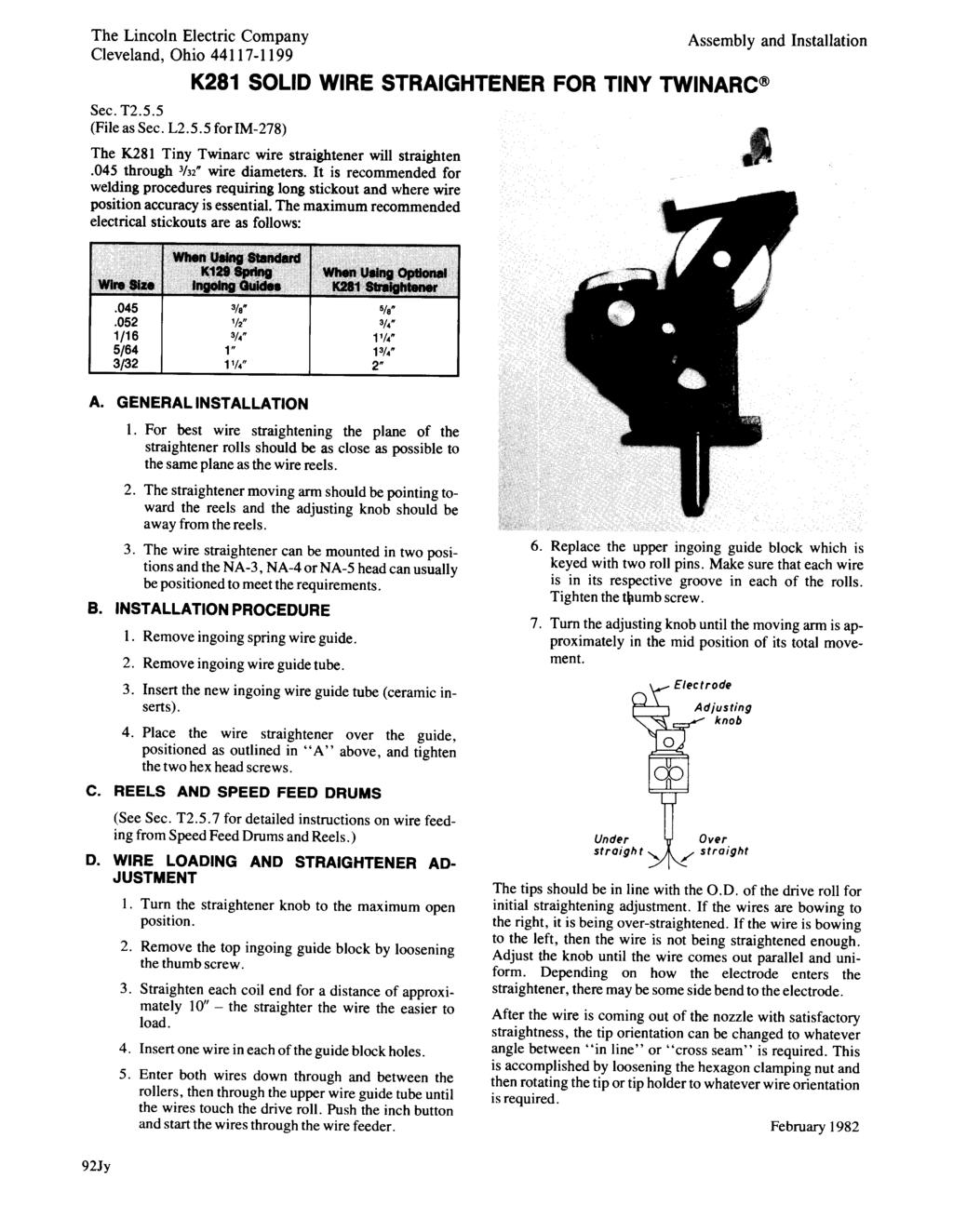
128 P-101-G.2.a P-101-G.2.a Part Numbers Part Numbers Part Numbers Part Numbers K281 WIRE STRAIGHTENER FOR TINY TWINARC 1 9 3C 3 4B 10 3B 4 4C A 5A B 4A 3C
129 P-101-G.2.b P-101-G.2.b Sub Assembly Illustration Sub Assembly Illustration Sub Assembly Illustration Sub Assembly Illustration USE COLUMN ONE FOR TINY TWINARC Specify Wire Size USE COLUMN TWO FOR TWIN MIG TORCH # Indicates a Change This Printing # # ITEM DESCRIPTION PART NO. QTY Base S X X 2 Tension Arm S X X 3 Roller Assembly, Includes: S X Roller Shaft (2 1/4 Shaft) T X Retaining Ring S X } } 3 Roller Assembly, Includes: S X X 3A Roller Shaft S X X (2 1/2 Shaft) 3B Bushing S X X 3C Retaining Ring S X X 4 Roller Assembly Includes: S X X Roller S X X Bearing Shaft S X X Retaining Ring S X X Bearing M X X 4A Hex Head Cap Screw 5/16-18 x X X 4B Lock Washer E106-A3 1 X X 4C Hex Nut 5/ X X 5 Incoming Guide Assembly, Includes: T X X 5A Thumb Screw T X X 5B Nozzle Insert (Not Shown) T X X 6 Roll Pin T X X 7 Adjusting Screw Assembly T X X 8 Large Pivot T X X 9 Retaining Ring S X X 10 Small Pivot Shaft T X X 12 Roll Pin T X X 13 Wire Guide Assembly T X 14 Set Screw S X X
130 P-101-H P-101-H Part Numbers Part Numbers Part Numbers Part Numbers 236 L P 241 SECTION AA FLUX HOPPER A T H
131 P-101-H.1 P-101-H.1 Sub Assembly Illustration Sub Assembly Illustration Sub Assembly Illustration Sub Assembly Illustration # Indicates a Change This Printing For the NA2, use the parts marked X in Column 1. For the NA3, NA4 and NA5, use the parts marked X in Column 2. For the NA454, use the parts marked X in Column 3. ITEM DESCRIPTION PART NO. QTY Flux Hopper Assembly, Includes: L3552-E 1 X Flux Hopper Assembly, Includes: (Standard) L3552-F 1 X Flux Hopper Assembly, Includes: L3552-G 1 X 225 Flux Hopper Base L X X X 226 Flux Gate Spring T X X X 227 Flux Gate Wear Plate T X X X 228 Flux Gate Spring T X X X 229 Flux Gate Assembly, Includes: S X X X Flux Gate: Sub Assembly S X X X Solenoid Plunger T X X X Spring Retaining Washer T X X X Retaining Ring S X X X Washer S X X X 234 Flux Tube Assembly S X X X 235 Sems Screw T X X X 236 Solenoid S X X X 237 Switch T X X X 241 Cable S X X 241 Cable M X X 250 Flux Hopper Assembly M10818 ø 1 X 250 Flux Hopper Assembly (Standard) M X 250 Flux Hopper Assembly M X 251 Sems Screw T X X X 252 Gasket T X X X 256 Flux Tube (Not Shown) T X 257 Flux Tube (Not Shown) S X Pointer and Mounting Bracket Assembly, Includes: T X Pointer and Mounting Bracket Assembly, Includes: T X 1 Pointer S X 1 Pointer S X 2 Insulating Washer S X X 3 Washer S X X 4 Wing Nut T X X 5 Hex Head Bolt T X X 6 Insulating Bushing T X X 7 Pointer Bracket M X X Door Hinge Assembly S X Hex Head Bolt, Hopper Mounting 1/4-20 x 6 2 X ø This part is obsolete and no longer available #
132 P-101-K P-101-K Part Numbers Part Numbers Part Numbers Part Numbers K148 CONTACT NOZZLE ASSEMBLY K149 LINC-FILL EXTENSION ASSEMBLY A A
133 P-101-K.1 P-101-K.1 Sub Assembly Illustration Sub Assembly Illustration Sub Assembly Illustration Sub Assembly Illustration # Indicates a Change This Printing Use Columns 1, 2 & 3 for Standard K148 Nozzles. Use Columns 4 & 5 for Modified Series Arc Equipment Nozzles. Use appropriate column for K149 Extensions based on wire size for standard extensions or Part No. for Modified Series Arc Equipment. ITEM DESCRIPTION PART NO. QTY Nozzle Asbly (Wire Size 3/ /8), Includes: K148A 1 X Nozzle Asbly (Wire Size 5/32-3/16), Includes: K148B 1 X Nozzle Asbly (Wire Size.068-5/64), Includes: K148C 1 X Nozzle Asbly (Wire Size 5/32-3/16), Includes: L & -6 1 X Nozzle Asbly (Wire Size 3/ /8), Includes: L X 1 1/2-13 x 1.5 HHCS CF X X X X X 2 1/2-23 HN CF X X X X X 3 Cable Connector S X X X X X 4 Roll Pin T X X X X X 5 Pivot Body M X X X X X 6 Guide Tube Asbly, 3/32,.120, 1/8 Wire KP X X 6 Guide Tube Asbly, 5/32, 3/16 Wire KP X X 6 Guide Tube Asbly,.068, 5/64 Wire KP X 7 Set Screw S X X X X X 8 Insulating Spacer T X X X X X 9 Flat Washer S X X X X X 10 Lock Washer E106A-2 2 X X X X X # 11 1/4-20 x 1.00 HHCS CF X X X X X 12 Nozzle Body M X X X X X 13 Insulating Tube T X X X X X 14 Insulation S X X X X X 15 Snap Ring S X X X X X 16 Pivot Pin T X X X X X 17 Spring T X X X X X 18 Nozzle Holder S X X X X X 19 Window Cover S X X X 20 Thread Protecting Collar S X X X X X 21 Nozzle Collar S X X X X X 22 Nozzle Tip KP X X X X 22 Nozzle Tip KP X 23 Inner Guide KP X 24 Extension Support Arm Mounting Bracket S X X 25 Set Screw S X X Water Cooling Tube Assembly (Not Illustrated) T X X X K149 Linc-Fill Extension Asbly, Includes: K149-3/32 Wire 1 X K149 Linc-Fill Extension Asbly, Includes: K Wire 1 X K149 Linc-Fill Extension Asbly, Includes: K149-1/8 Wire 1 X K149 Linc-Fill Extension Asbly, Includes: K149-5/32 Wire 1 X K149 Linc-Fill Extension Asbly, Includes: K149-3/16 Wire 1 X Linc-Fill Extension Asbly & L Nozzle, Includes: M X 102 Extension Arm Asbly S X X X X X X 103 Mounting Block S X X X X X 104 Set Screw S X X X X X 105 1/4-20 x 1 3/8 HHCS CF X X X X X X 106 Insulation T X X X X X X 107 Insulating Tube T X X X X X X 108 Lock Washer E106A-2 2 X X X X X X 108A Plain Washer S X X X X X X 109 1/4-20 HN CF X X X X X X 110 Flux Hose Clamp T X X X X X 111 5/8-11 HJN CF X X X X X X 112 Extension Tube - 2 Long KP X X X 113 Extension Tube - 1 Long KP X X 114 Extension Tube End (2 3/4 Electrical Stickout) KP X 114 Extension Tube End (2 1/4 Electrical Stickout) KP X 114 Extension Tube End KP X X 114 Extension Tube End KP X 114 Extension Tube End KP X X 115 Flux Hose T X X X X X 116 Flux Hose S X X X X X Nozzle Assembly (L4261-6) See Above List 1 X
134 P-101-L P-101-L Part Numbers Part Numbers Part Numbers Part Numbers L J K225 SUBMERGED ARC TWINARC KIT
135 P-101-L.1 P-101-L.1 Sub Assembly Illustration Sub Assembly Illustration Sub Assembly Illustration Sub Assembly Illustration # Indicates a Change This Printing ITEM DESCRIPTION PART NO. QTY Twinarc - Complete - Includes All Below K225 Nozzle Assembly - Includes Items 101 through 129 L Adapter Plate M Adapter Insulation T Socket Head Screw T Washer S Insulating Washer S Insulating Bushing T Electrode Guide Tube KP Socket Plate S Nozzle Body M Current Bar S /4-20 x 1.00 HHCS CF Center Contact Block (.375 Electrode Spacing) T Center Contact Block (.500 Electrode Spacing) T Center Contact Block (.625 Electrode Spacing) T Line Up Plate T Socket Head Screw T Spring S Spring Insulation T Insulating Bushing T Washer S Lock Washer E106A /4-20 x 1.00 HHCS CF Contact Jaw T /2-13 x 1.50 HHS CF /2-13 HN CF Socket Head Screw T Washer T Nameplate S Drive Screw S Flux Tube Support Assembly T /16-18 x 3/4 HHCS CF Outer Drive Rolls KP Center Drive Roll S Drive Roll Spacer T Idle Roll Assembly S Drive Roll Key M Wire Guide Tubes - Upper & Lower KP Wire Straightener See P-100-M 1 Second Wire Reel & Reel Mounting See P-100-G
136 P-101-L.2 P-101-L.2 Part Numbers Part Numbers Part Numbers Part Numbers L M K239 INNERSHIELD TWINARC KIT Water cooled jacket asbly. Wire guide block asbly N.B Socket HD. screw Part of item 14
137 P-101-L.3 P-101-L.3 Sub Assembly Illustration Sub Assembly Illustration Sub Assembly Illustration Sub Assembly Illustration # Indicates a Change This Printing ITEM DESCRIPTION PART NO. QTY Twinarc - Complete - Includes All Below K239 Nozzle Assembly L ø 1 Adapter Plate & Roll Pin Assembly M Hex Head Screw 5/16-18 x Socket Head Screw T Flat Washer S Insulating Washer S Insulating Bushing T Adapter Insulation T Socket Plate S Socket Head Screw T Electrode Guide Tube T Nameplate S Drive Screw S Round Head Screw 1/4-20 x Lock Washer E106A Clamp T Contact Block S Socket Head Screw T Jacket & Guide Block Assembly S Hex Head Screw 3/8-16 x Flat Washer S Lock Washer E106A Hex Nut 3/ Contact Tip T / Current Bar S Hex Head Screw 1/4-20 x Hex Head Screw 1/2-13 x Hex Nut 1/ Nozzle Body M Conductor Bar Insulation T Insulating Sleeve T Tip Insulation T Insulating Sleeve T Water Jacket Insulation T Flat Washer S Flat Washer S Outer Drive Rolls S Center Drive Roll S Drive Roll Spacer T Idle Roll Assembly S Drive Roll Key M Wire Guide Tubes - Upper & Lower S Wire Straightener See P-100-N 1 Second Wire Reel & Reel Mounting See P-100-G 1 ø This part is obsolete and no longer available #
138 P-101-M P-101-M Part Numbers Part Numbers Part Numbers Part Numbers K231 (and K31*) CONTACT NOZZLE ASSEMBLY * For K31, order K231 assembly. All parts are interchangeable. 111A B 113A C
139 P-101-M.1 P-101-M.1 Sub Assembly Illustration Sub Assembly Illustration Sub Assembly Illustration Sub Assembly Illustration # Indicates a Change This Printing Nozzle Assembly, Includes Items 110 thru 125 as appropriate for wire size specified K231* 1 X Nozzle Assembly, for LT34 ONLY, Includes Items 110, 111, 118, 121 and 122; Order Items 119, 120, 123, 124 and 125 separately for the desired wire size M X 110 Nozzle Insulator S X X 111 Nozzle Body S X X 111A Roll Pin T X X 113A Cone Body Assembly, Includes: M X 113B Flux Cone Plug S X 113C Roll Pin T X 114 Retaining Nut S X 115 Flux Cone KP X 116 Locking Ferrule T X 117 Thumb Screw T X 118 Special Socket Head Screw T X 119 Rubber Flux Tube (Not Shown) T X 119 Rubber Flux Tube, LT34 Only (Not Shown) T X 120 Steel Flux Tube (Not Shown) T X 120 Steel Flux Tube, LT34 Only (Not Shown) S X 121 1/2-13 x 1.50 HHCS - Lead to Nozzle CF X X 122 1/2-13 HN - Lead to Nozzle CF X X 123 Contact Tip - 7/32 Wire Size KP X X 123 Contact Tip - 3/16 Wire size KP X X 123 Contact Tip - 5/32 Wire Size KP X X 123 Contact Tip - 1/8 Wire Size KP X X 123 Contact Tip - 3/32 Wire Size KP X X 123 Contact Tip - 3/32 Wire Size; (3/8-24 Thread) Old Style KP X X 123 Contact Tip - 3/32 Wire Size; (5/16-18 Thread) KP X X 123 Contact Tip - 5/64 Wire Size; (3/8-24 Thread) Old Style KP X X 123 Contact Tip - 5/64 Wire Size; (5/16-18 Thread) See Note 1 T /64 1 X X 124 Adapter for 3/32 and 5/64 S8087 Tips (With 3/8-24 Female Thread) See Note 2 1 X X 124 Adapter for 3/32 and 5/64 T14050 Tips (With 5/16-18 Female Thread) KP X X 125 Nozzle Insert for 3/32 and 5/64 Wire (For NA) S /32 1 X 125 Nozzle Insert for 5/64 Wire (For LAF & LT) KP X X Mounting Clip (For Mounting Nozzle on LAF2) T10714 ø 2 X Nozzle Extension (5.38 long) (For 3/32 & Larger Wire) S12003 As Reqʼd X * Specify Wire Size Note 1 When tip life is limited by tip being fused over, the use of T /64 Tips may result in a lower overall cost. Note 2 This adapter is no longer available, order Adapter S16844 and the appropriate T14050 Tips or T /64 Tip. Use only the parts marked X in the column under the heading number called for in the model index page. ITEM DESCRIPTION PART NO. QTY #
140 P-101-N P-101-N Part Numbers Part Numbers Part Numbers Part Numbers M J K226 (and K32*) CONTACT JAW ASSEMBLY * For K32, order a K226 assembly. All parts are the same except Item
141 P-101-N.1 P-101-N.1 Sub Assembly Illustration Sub Assembly Illustration Sub Assembly Illustration Sub Assembly Illustration # Indicates a Change This Printing ITEM DESCRIPTION PART NO. QTY Contact Jaw Assembly - One Rectangular and One Tapered Jaw - For 1/8 thru 7/32 Wire, Includes: K226-R 1 Contact Jaw Assembly - Two Tapered Jaws - For 3/32 and 1/8 Wire, Includes: K226-T 1 1 Socket Head Screw T Washer S Insulating Washer S Insulating Bushing T Cover Plate T Lead Block S Hex Jam Nut 3/ Adapter Plate, Rectangular* M12478* 1 9 Insulation Plate T Bottom Wire Guide M Spring Insulation T Hex Head Cap Screw 1/4-20 x Insulating Bushing T Hex Head Cap Screw 3/8-16 x Hex Head Cap Screw 1/2-13 x N Hex Jam Nut 1/ Lock Washer E106A Plain Washer S Spring S Hex Head Cap Screw 3/8-16 x Plain Washer S or 3 21 Contact Block - Rectangular S Contact Block - Tapered S Hex Head Cap Screw (K226-R Only) 3/8-16 x Hex Head Cap Screw (K226-R) 3/8-16 x Hex Head Cap Screw (K226-T) 3/8-16 x Braided Lead (K226-R Only) S Contact Jaw S Flux Tube Clip T Hex Head Cap Screw 3/8-16 x Hex Head Screw 5/16-18 x Flux Hose T Flux Hose Tip S * Item 8 for K32 Jaws Sold with LAF and LT3 Tractors was round Part S
142 P-101-P (Supersedes P-52-C) P-101-P (Supersedes P-52-C) Part Numbers Part Numbers Part Numbers Part Numbers CONTROL BOX G B 93 FULL SCALE CUT-AWAY VIEW SHOWING LAF3,4, & 5 CONTROL BOX MOUNTING 94 CONTROL BOX 91 TRAVEL CARRIAGE GENERAL ASSEMBLY 92 TAPE ITEM 22 TO HANDLE WITH 75 WIDE TAPE PER E651 FOR SHIPMENT 93 FULL SCALE CUT-AWAY VIEW SHOWING NA3 & NA4 CONTROL BOX MOUNTING C B A STENCIL CODE NUMBER.19 HIGH NUMBERS FULL SCALE VIEW SHOWING UPPER GUIDE WHEELS & MOUNTING
143 Sub Assembly Illustration Sub Assembly Illustration Sub Assembly Illustration Sub Assembly Illustration P-101-P.1.a (Supersedes P-52-C.1) # Indicates a Change This Printing For K23 & K236 Models (below code 7500), use the parts marked X in Column 1. For K247 Models (above code 7500), use the parts marked X in Column 2. For K247-HC Models (above code 7500), use the parts marked X in Column 3. ITEM DESCRIPTION PART NO. QTY A Motor and Gear Box Assembly See P-101-R B Control Panel Assembly See P-101-O 1 Carriage Frame G X X X 2 Upper Guide Wheel Assembly, Includes: T X 2 Upper Guide Wheel Assembly, Includes: T X 2 Upper Guide Wheel Assembly, Includes: T X Shaft T X Shaft S X X Bearing M X X Bearing M X Retaining Ring S X X 3 Roll Pin T X X Lockwasher - Guide Wheel Mounting E106A-5 6 X Washer - Guide Wheel Mounting S X 5 Lower Bearing Bar Assembly S X 5 Lower Bearing Bar Assembly M X 5 Lower Bearing Bar Assembly M X 6 Spacer - Thin S ø 4 X 6 Spacer - Thin S X X 7 Spacer - Thick S ø 8 X 7 Spacer - Thick S X Lockwasher, Lower Bearing Bar Mounting E106A-4 4 X 9 Socket Head Screw T ø 4 X 9 Socket Head Screw T X X C Head Mounting and Lift L X C Head Mounting and Lift L X X Head Mounting Parts See P-101-Q 1 X X X 19 Lift Handle M X 19 Lift Handle M X X 20 Lift Handle Stud T X 20 Lift Handle Stud T X X 21 Set Screw, Lift Handle and Stud Mounting S X Hex Jam Nut, Locking Set Screw 3/ X 21 Roll Pin, Lift Handle Mounting T X X 22 Roller, Mounts Item C thru Crank Bracket T X X X 23 Gear Box Mounting Plate M8485 ø 1 X X X 24 Flat Head Screw 5/16-18 x X X X 25 Drive Wheel T X X X Key, Drive Wheel to Motor M X X X Spacer S X X X Lockwasher T X X X 26 Nut, Drive Wheel to Motor T X X X 27 Swivel Motor Mount S X X 27 Swivel Motor Mount S X 28 Oil Cup T X X X 29 Hex Head Bolt 1/2-13 x X 29 Hex Head Bolt 1/2-13 x X X 30 Lockwasher E106A-5 2 X X X 31 Upper Spring Bracket S X X X 32 Hex Head Bolt 3/8-16 x.75 2 X X X ø This part is obsolete and no longer available. P-101-P.1.a (Supersedes P-52-C.1) #
144 Sub Assembly Illustration Sub Assembly Illustration Sub Assembly Illustration Sub Assembly Illustration P-101-P.1.b (Supersedes P-52-C.1) # Indicates a Change This Printing For K23 & K236 Models (below code 7500), use the parts marked X in Column 1. For K247 Models (above code 7500), use the parts marked X in Column 2. For K247-HC Models (above code 7500), use the parts marked X in Column 3. ITEM DESCRIPTION PART NO. QTY Lockwasher E106A-4 2 X X X 34 Spring T X X X 35 Shim - Swivel Motor Mount T As Reqʼd X X X 35 Shim - Swivel Motor Mount T X X X 37 Cable Clamp M X X X 73 Choke Coil M X X X Cable - To Travel Receptacle in Control Box, Includes: M X X X Plug S X X X 76 Wire Reel Support L X X X Control Box Mounting Parts 88 Insulation Tube T X X X 89 Insulation Washer S X X X 90I Insulation Spacer S X X X 90A Adapter Plate S X X X 91 Hex Head Screw 1/4-20 x.75 6 X X X 92 Plain Washer S X X X 93 Lockwasher E106A-2 6 X X X 94 Hex Nut 1/ X X X Carriage Type Number For LAF & NA2 For NA3 & NA4 For NA3 & NA4 Gear Ratio K23-F K236-F K247 & -HC -F Fast 144 : 1 K23-M K236-M K247 & -HC -M Medium 324 : 1 K23-S K236-S K247 & -HC -S Slow 648 : 1 P-101-P-1.b (Supersedes P-52-C.1)
145 P-101-Q (Supersedes P-52-D) P-101-Q (Supersedes P-52-D) Part Numbers Part Numbers Part Numbers Part Numbers # Indicates a Change This Printing HEAD MOUNTING AND LIFT MECHANISM For K23 and K236 Models (Below Code 7500) use the parts marked X in column 1. For K247 and K247-HC Models, (Above Code 7500) and K325 and K325-HC Models, use the parts marked X in column 2. ITEM DESCRIPTION PART NO. QTY C Head Mounting and Lift Mechanism (Includes all Below) L X C Head Mounting and Lift Mechanism (Includes all Below) L X 10 Head Lift Mounting Plate S X 10 Head Lift Mounting Plate S X 11 Lift Link S X 11 Lift Link S X 12 Roller Shaft S X X 13 Roller T X X 14 Roll Pin - Roller to Roller Shaft T X X 15 Crank Link Shaft S ø 1 X 15 Crank Link Shaft S X 16 Roll Pin - Locates Lift Link on Crank Link Shaft T X X 17 Link Shaft S ø 1 X 17 Link Shaft S X 18 Crank Bracket S10285 ø 1 X 18 Crank Bracket T X # # # ø This part is obsolete and no longer available
146 P-101-R (Supersedes P-52-F) P-101-R (Supersedes P-52-F) Part Numbers Part Numbers Part Numbers Part Numbers A # Indicates a Change This Printing CARRIAGE DRIVE MOTOR AND GEAR CASE Use only the parts marked X in the column under the heading number called for in the model index page. ITEM DESCRIPTION PART NO. QTY A Drive Motor and Gear Case Assembly, Ratio, Includes All items in Column 1 Marked X. L3094-1* ø 1 X A Drive Motor and Gear Case Assembly, Ratio, Includes All items in Column 2 Marked X. L3094-2* 1 X A Drive Motor and Gear Case Assembly, Ratio, Includes All items in Column 3 Marked X. L3094-4* ø 1 X 175 Gear Case G1027 ø 1 X X X 176 Dust Cap - For Output Shaft T X X X 177 Dust Cap Gasket T As Reqʼd X X X 178 Dust Cap Gasket T ø As Reqʼd X X X 179 Flat Head Screw - Dust Cap to Case x 1/2 4 X X X 180 Dust Cap - For Cross Shaft T10672 ø 1 X X X # # ø This part is obsolete and no longer available
147 P-101-R.1 P-101-R.1 Sub Assembly Illustration Sub Assembly Illustration Sub Assembly Illustration Sub Assembly Illustration # Indicates a Change This Printing 181 Caution Plate S X X X 182 Round Head Screw - Dust Cap to Gear Case #10-24 x 1/2 4 X X X 183 Lock Washer E106A-1 4 X X X 184 Small Bearing Cage S X X X 185 Small Bearing Cage Gasket S X X X 186 Flat Head Screw - Small Cage to Gear Case #10-24 x 1/2 4 X X X 187 Large Bearing Cage S X X X 188 Large Bearing Cage Gasket S X X X 189 Flat Head Screw - Large Cage to Gear Case #10-24 x 1/2 6 X X X 190 Oil Seal - Output Shaft S X X X Motor Assembly Ratio Only, Includes: M X Motor Assembly and Ratio, Includes: M X X 191 Motor NSS 1 X X X Brush and Spring Assembly L ø 2 X X X Brush Cap L ø 2 X X X Phillips Flat Head Screw, Motor to Base 8-32 x 1 4 X X X Input Worm, Ratio Only S X Input Worm, and Ratio S X X Roll Pin, Input Worm to Motor Shaft T X X X Four Contact Plug T X X X Oil Throw Ring S X X X Cross Shaft Assembly, Ratio Only, Includes Items 199 through 202 S ø 1 X Cross Shaft Assembly, Ratio Only, Includes Items 199 through 202 S X Cross Shaft Assembly, Ratio Only, Includes Items 199 through 202 S X 199 Cross Shaft, Ratio Only S ø 1 X 199 Cross Shaft, Ratio Only S X 199 Cross Shaft, Ratio Only S X 200 Input Worm Gear, Ratio Only S X 200 Input Worm Gear, and Ratio S X X 201 Ball Bearing M X X X 202 Woodruff Key #405 1 X X X Output Shaft Assembly, Ratio Only, Includes Items 203 through 208 S ø 1 X Output Shaft Assembly, Ratio Only, Includes Items 203 through 208 S X Output Shaft Assembly, Ratio Only, Includes Items 203 through 208 S X 203 Output Shaft S X X X 204 Output Shaft Worm Gear, Ratio Only S ø 1 X 204 Output Shaft Worm Gear, Ratio Only S X 204 Output Shaft Worm Gear, Ratio Only S X 205 Ball Bearing M X X X 206 Ball Bearing T X X X 207 Snap Ring S X X X 208 Woodruff Key #606 1 X X X 209 Motor Base Gasket T X X X 210 Round Head Screw, Motor Base to Gear Case #10-24 x 3/4 3 X X X 211 Lock Washer, Motor Base to Gear Base E106A-1 3 X X X 213 Slotted Pipe Plug S ø 1 X X X Gear Box Lubricant T X X X * To order a gear box assembly without a motor, add -W to this assembly number. ø This part is obsolete and no longer available. NSS - Not sold separately. Use only the parts marked X in the column under the heading number called for in the model index page. ITEM DESCRIPTION PART NO. QTY # # #
148 P-101-S P-101-S Part Numbers Part Numbers Part Numbers Part Numbers L P K29 VERTICAL HEAD LIFT ASSEMBLY NA1, 2, 3, 4 and 5 and LAF3, 4 and
149 P-101-S.1 P-101-S.1 Sub Assembly Illustration Sub Assembly Illustration Sub Assembly Illustration Sub Assembly Illustration # Indicates a Change This Printing In mid 1978 the K29 was redesigned. Old design assemblies may be identified by three socket head screws in the head lift lock area. New design assemblies have only one socket head screw. Use parts marked X in Column 1 for old design. Use parts marked X in Column 2 for new design. ITEM DESCRIPTION PART NO. QTY Head Lift Housing K29 1 X 1 Head Lift Housing L X 2 Head Lift Tube M X 2 Head Lift Tube M X 3 Head Lift Lock Pin S X 3 Locating Key T X 4 Socket Head Cap Screw T X 4 Socket Head Cap Screw T X 5 Spring T X 6 Spring Retainer S X 7 Snap Ring S X 8 Head Lift Screw Assembly, Includes: S X X Head Lift Screw S X X Ball Bearing M X X Snap Ring S X X Gear S X X Woodruff Key #404 1 X X 9 Boot S X X 10 Clamp S X X 11 Clamp S X X 12 Adjusting Shaft Assembly, Includes: S X X Crank Arm Assembly T X X Snap Ring S X X Thrust Washer S X X Drive Pin T X X Shaft T X X Bearing Retainer S X X Needle Bearing S X X Oil Seal S X X 13 Round Head Screw #10-24 x.50 2 X X 14 Lock Washer E106A-1 2 X X 15 Oil Cup T X X 16 Needle Bearing S X X 17 Thrust Washer S X X 18 Cover Plate T X X 19 Lock Washer E106A-1 2 X X 20 Round Head Screw #10-24 x.50 2 X X 21 Expansion Plug T X X 22 Shim T10601 As Reqʼd X 23 Locking Plate T X 24 Socket Head Cap Screw T X 25 Lock Washer E106A-2 2 X
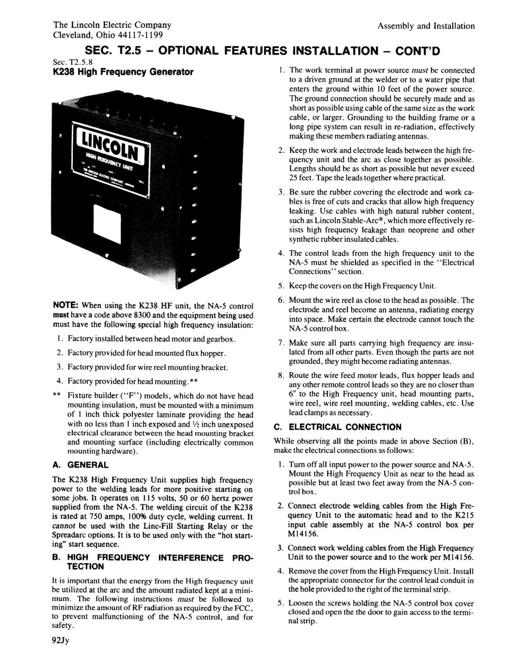
150 P-101-T.a P-101-T.a Part Numbers Part Numbers Part Numbers Part Numbers HI-FREQ CAPACITOR L TRANSFORMER HIGH FREQUENCY UNIT K238 SPARK GAP ASSBLY RESISTOR T CASE TERMINAL STRIP CAPACITOR RELAY AIR CORE TRANSFORMER SPARK GAP MOUNTING PANEL AND BRACKET
151 P-101-T.b P-101-T.b Sub Assembly Illustration Sub Assembly Illustration Sub Assembly Illustration Sub Assembly Illustration # Indicates a Change This Printing ITEM DESCRIPTION PART NO. QTY High Frequency Unit, Includes: K238 1 Capacitor S Transformer M15359 ø Resistor S Case L Case Cover L Nameplate M Terminal Strip S Number Plate T Relay S Spark Gap Assembly S Electrode T R. F. Choke T Air Core Transformer L ø This part is obsolete and no longer available # #
152 P-101-U.a P-101-U.a Part Numbers Part Numbers Part Numbers Part Numbers N.E SECTION THRU NOZZLE TIP (WITH JACKET REMOVED) DOUBLE SIZE K386 NARROW GAP DEEP GROOVE SUBMERGED ARC NOZZLE G
153 P-101-U.b P-101-U.b Sub Assembly Illustration Sub Assembly Illustration Sub Assembly Illustration Sub Assembly Illustration # Indicates a Change This Printing ITEM DESCRIPTION PART NO. QTY Nozzle Tip T / Hollow Set Screw T Ceramic Insert T Ceramic Insert T Spring Liner T Nozzle Tube Assembly S Insulation Jacket S Cooling Bar Assembly S Nozzle Pivot Hub Assembly T Set Screw S Key M Rotational Lock Screw Assembly T Snap Ring S Pivot Assembly T Nozzle Insulator Assembly S Socket Head Screw T Nozzle Insert Assembly S Pressure Belt T Pressure Arm Assembly T Socket Head Cap Screw T Flux Tube Clamp S Button Head Socket Screw T Hex Head Screw 1/4-20 x Plain Washer S Wing Nut T Flux Tube T Pivot Housing Arm M Lock Washer E106-A14 3 Hex Head Screw 5/16-18 x Mounting Clamp Assembly S Roll Pin T Plain Washer S Roll Pin T Pivot Handle T Hex Head Screw 1/2-13 x Flange Nut T Nozzle Tube Strap T Items Not Illustrated: Flux Hopper Extension Bracket S Flux Hopper Extension Pin S Extension Pin Nut 1/ Flex Tube T #
154 P-101-V P-101-V Part Numbers Part Numbers Part Numbers Part Numbers L # Indicates a Change This Printing K405 AUTOMATIC INNERSHIELD NOZZLE 1 ITEM DESCRIPTION PART NO. QTY Nozzle Tip Wire Size S Nozzle Tip Wire Size S Nozzle Tip - 5/64 Wire Size S / Nozzle Tip - 3/32 Wire Size S / Nozzle Tip Wire Size S Straight Nozzle Assembly.062-3/32 Wire Size M Straight Nozzle Assembly.122 Wire Size M ø 1 3 Collar S Nozzle Body Assembly S Socket Head Screw T Nozzle Insulator Assembly S Nozzle Insert Assembly.062-3/32 Wire Size Only S Hex Head Screw 1/2-13 x Hex Nut 1/ # ø This part is obsolete and no longer available
155 NOTES
156 P-114-H P-114-H Part Numbers Part Numbers Part Numbers Part Numbers L Q # Indicates a Change This Printing K224 SOLID-STATE REMOTE FIELD CONTROL (DISCONTINUED) ITEM DESCRIPTION PART NO. QTY Solid State Remote Field Control, Includes: K Top Door M Terminal Strip S Number Plate T Capacitor S Auto Transformer M12702 ø 1 6 Box Assembly M12706 ø 1 7 Transformer S15257 ø 1 8 Capacitor T Nameplate M Polarity Switch S13417 ø 1 11 Fuse Holder S Fuse T Capacitor S Diode T SCR and Heat Sink M13342 ø 1 15 Control P.C. Board (Code 7359 Only) L Control P.C. Board (Code 7683 & Above) L Caution Decal T Choke S Resistor (Code 7742 & Above) T F 1 K224 Mounting Angles S & 1 ea S # ø This part is obsolete and no longer available
157 P-114-J P-114-J Part Numbers Part Numbers Part Numbers Part Numbers K285 CONCENTRIC FLUX CONE 6 6 # Indicates a Change This Printing ITEM DESCRIPTION PART NO. QTY Concentric Flux cone, Includes: K285 1 X 1 Side Plate T X 2 Thumb Screw T X 3 Support Arm M X 4 Sems Screw T X 5 Flux Cone M X 6 Hose Clamp S X Items Not Illustrated Flux Hose T X Flux Hose Tube T X
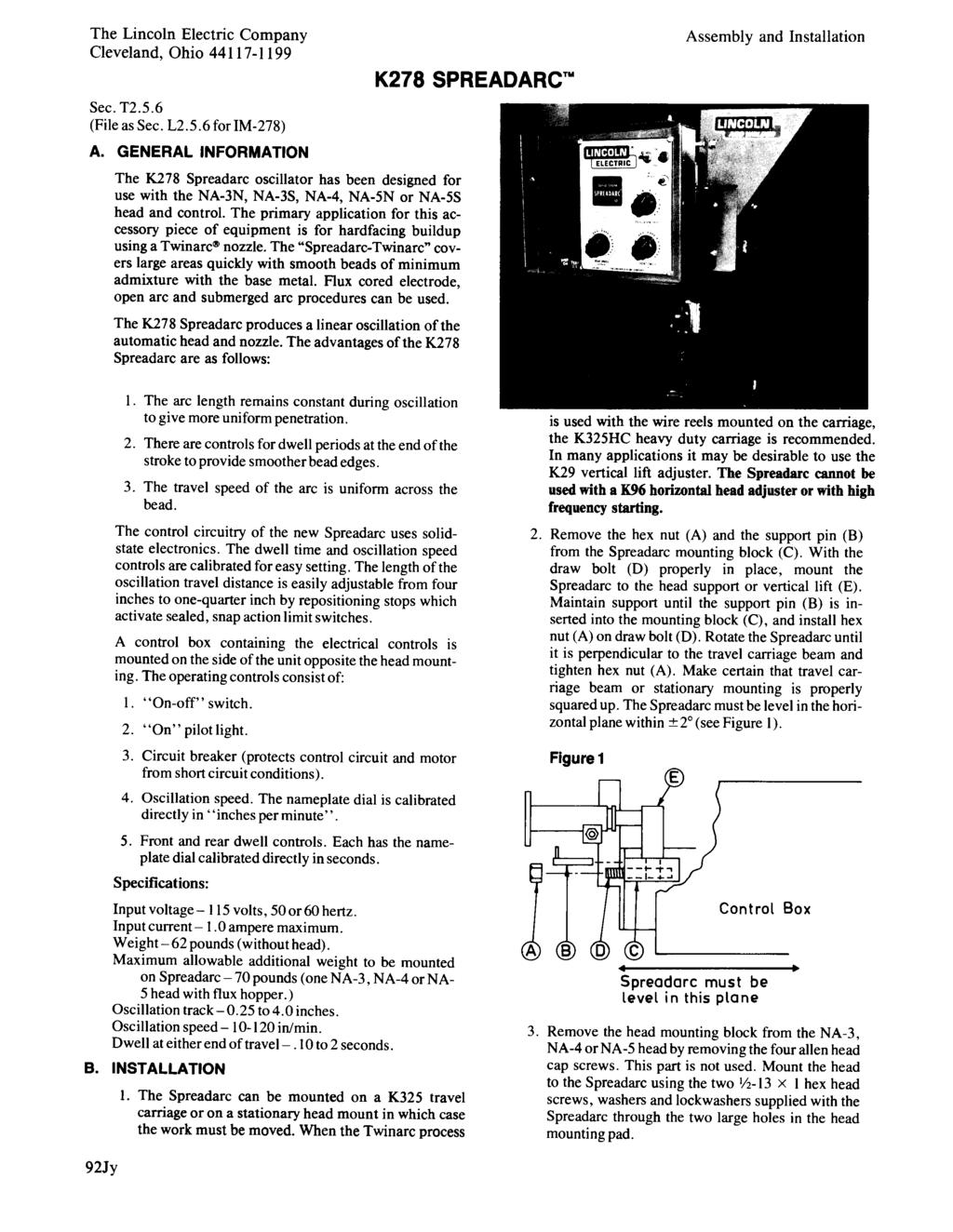
158 P-114-K.2 P-114-K.2 Part Numbers Part Numbers Part Numbers Part Numbers K278-1 SPREADARC COMPLETE ASSEMBLY
159 P-114-K.3 P-114-K.3 Sub Assembly Illustration Sub Assembly Illustration Sub Assembly Illustration Sub Assembly Illustration # Indicates a Change This Printing 1 Carriage & Track Assembly See P-114-L Bottom Shield M Thread Forming Screw S Top Shield M #10-24 x.50 HHCS CF Lock Washer T Proximity Sensor Bracket M Grommet T #10-24 X.50 HHCS CF Lock Washer T Proximity Sensor Assembly M Control Box Assembly See P-114-P 1 8 Carriage Guard M Thread Forming Screw S Draw Bolt T /4-10 HN CF Support Pin Assembly T Grommet T Decal T Decal S Guard M #10-24 x.50 HHCS CF Lock Washer T Decal T Use only the parts marked X in the column under the heading number called for in the model index page. ITEM DESCRIPTION PART NO. QTY #
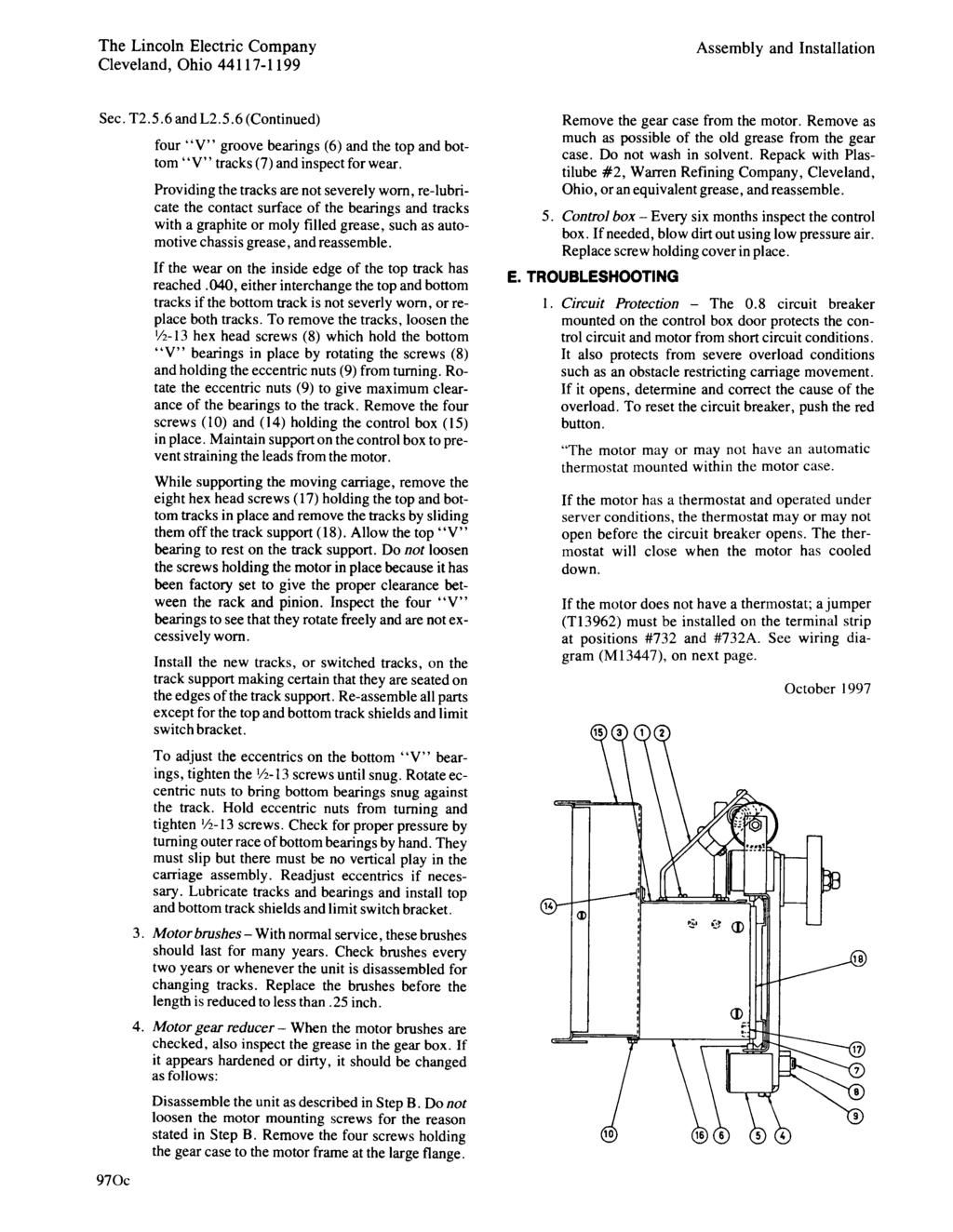
160 P-114-L.2 P-114-L.2 Part Numbers Part Numbers Part Numbers Part Numbers SPREADARC CARRIAGE, TRACK & DRIVE MOTOR ASBLY (K278-1) # Indicates a Change This Printing 2 3 Use only the parts marked X in the column under the heading number called for in the model index page. ITEM DESCRIPTION PART NO. QTY Carriage & Track Asbly (L12002), Includes: NSS 1 Carriage Assembly See P-114-M Track Assembly (M20165), Includes: NSS 1 Track Support Welded Assembly M Track S /8-16 x.625 HHCS CF Lock Washer E106A-16 8 Plain Washer S Drive Motor Assembly L A Plain Washer (Not Shown) S B Hex Lock Nut (Not Shown) T Plug Button T
161 NOTES
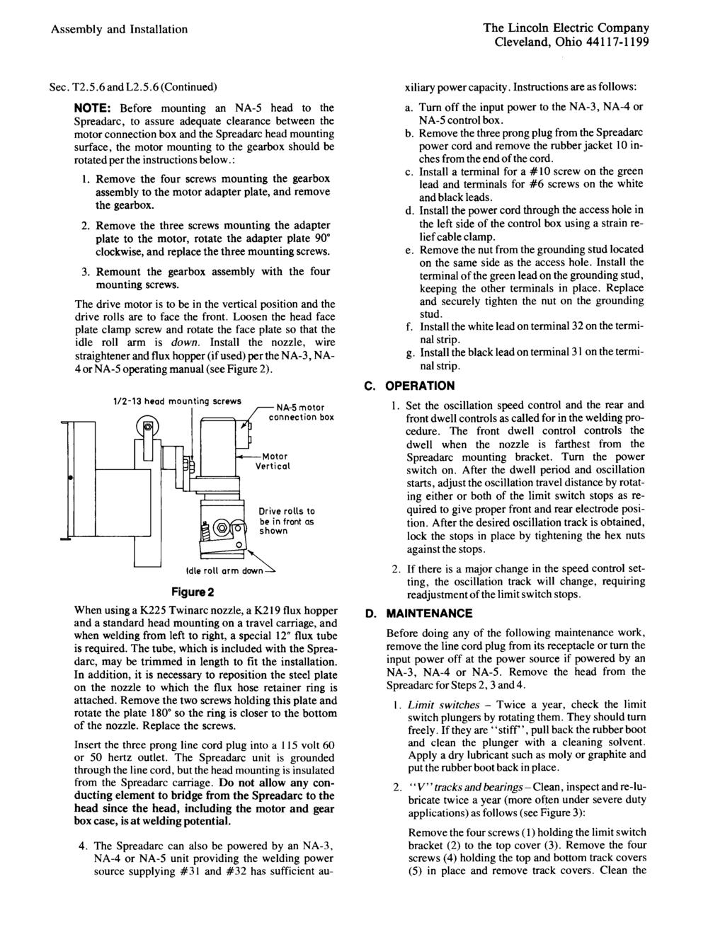
162 P-114-M.1 P-114-M.1 Part Numbers Part Numbers Part Numbers Part Numbers 8C 8D 1 4C 4B 4D 4E SPREADARC CARRIAGE ASSEMBLY (K278-1) 5 6 4A 4F 2A 2C 2D 2E 8B 3C 3B 2B 3A 8A 7E 7C 7A 2J 2F 7B 2G 2H 2D 7D
163 P-114-M.2 P-114-M.2 Sub Assembly Illustration Sub Assembly Illustration Sub Assembly Illustration Sub Assembly Illustration # Indicates a Change This Printing ITEM DESCRIPTION PART NO. QTY Carriage Assembly (L12007), Includes NSS 1 Carriage M A Head Mounting Plate S B 1/2-13 x 2.50 HHCS CF C Lock Washer E106A D Plain Washer S E Insulating Washer S F Insulating Tube T G Bearing Bushing T H V Roller S J 1/2-13 HN CF A 1/2-13 x 1.50 HHCS CF B Plain Washer S C Lock Washer E106A A Eccentric Adjuster T B V Roller S C Bearing Bushing T D Plain Washer S E Lock Washer E106A F 1/2-13 x 2.25 HHCS CF Head Insulation S Head Support S A Stud T B Insulating Tube T C Cam S D 3/8-16 HN CF E Lock Washer E106A A Drive Shaft Rack S B Spacer T C Socket Head Cap Screw T D Lock Washer T4291-A 3 NSS - Not Sold Separately
164 P-114-N P-114-N Part Numbers Part Numbers Part Numbers Part Numbers 4 1 M F # Indicates a Change This Printing K237 LINC-FILL STARTING RELAY ASSEMBLY Use only the parts marked X in the column under the heading number called for in the model index page. ITEM DESCRIPTION PART NO. QTY Box Welded Assembly S X 1 Box Welded Assembly S ø 1 X 2 Box Cover S X X Self Tapping Screw S X X 3 Box Connector T or 2 X X 4 Grommet S X 5 Jumper S X 6 Jumper T X 7 Thread Forming Screw S X X Hex Nut # X X 8 Solid State Relay S X X 9 AC Contactor Order Kit S X 9 AC Contactor M X 10 Warning Decal T X X 13 or 14 Terminal Strip Assembly, Includes: T X X Capacitor T X X Resistor T X X NOTE: This parts list covers two versions of the K237 Assembly. One built before Sept iden tified by one box connector and two grommets located in the box tops, and one built after Sept with two box connectors in the box top. Use column one for assemblies built before Sept Use column two for assemblies built after Sept #
165 P-132-A RETURN TO MAIN INDEX P-132-A TC-3 SELF-PROPELLED TRAVEL CARRIAGE Parts Lists Index This parts list covers machines thru Code For Codes above 9021 contact Service Dept. For K325-S, K325-F, (Use Column One on P-132-C, -D, & -F) For K325-HC, K325-HC-F, (Use Column Two on P-132-C, -D, & -F) # # TC-3 General Assembly P-132-C Motor and Gear Box Assembly P-132-D Gear Box Assembly P-132-E Travel Control Box Assembly P-132-F
166 P-132-C P-132-C Part Numbers Part Numbers Part Numbers Part Numbers G A TC-3 GENERAL ASSEMBLY
167 P-132-C.1 P-132-C.1 Sub Assembly Illustration Sub Assembly Illustration Sub Assembly Illustration Sub Assembly Illustration # Indicates a Change This Printing Use only the parts marked X in the column under the heading number called for in the model index page. ITEM DESCRIPTION PART NO. QTY Carriage Assembly (K325-S 5-75 in/min) Includes: (Below Code 8400) G X Carriage Assembly (K325-S 5-75 in/min) Includes: (Code 8400 to 9000) G X Carriage Assembly (K325-S 5-75 in/min) Includes: (Above Code 9000) G X Carriage Assembly (K325-F in/min) Includes: (Below Code 8400) G X Carriage Assembly (K325-F in/min) Includes: (Code 8400 to 9000) G X Carriage Assembly (K325-F in/min) Includes: (Above Code 9000) G X Carriage Assembly (K325-HC-S 5-75 in/min) Includes: (Below Code 8400) G X Carriage Assembly (K325-HC-S 5-75 in/min) Includes: (Code 8400 to 9000) G X Carriage Assembly (K325-HC-S 5-75 in/min) Includes: (Above Code 9000) G X Carriage Assembly (K325-HC-F in/min) Includes: (Below Code 8400) G X Carriage Assembly (K325-HC-F in/min) Includes: (Code 8400 to 9000) G X Carriage Assembly (K325-HC-F in/min) Includes: (Above Code 9000) G X 1 Hex Head Screw 1/4-20x.75 3 X X 2 Lockwasher E106A-2 3 X X 3 Hex Nut 1/ X X 4 Cable Clamp M X X 7 Head Mounting and Lift Mechanism See P-101-Q 1 X X Lift Hand Stud T X X Roller T X X Roll Pin T X X 8 Carriage Frame Assembly G X X 9 Gear Box Mounting Plate M X X 10 Swivel Motor Mount S X X 11 Shim (.0179 Thick) (Not Shown) T As Reqd. X X 11 Shim (.0598 Thick) (Not Shown) T X X 11 Shim (.1875 Thick) (Not Shown) S X 12 Hex Head Bolt 1/2-13x X 12 Hex Head Bolt 1/2-13x X 13 Lockwasher E106A-5 2 X X 14 Plain Washer S X X 15 Spring T X X 16 Motor and Gear Box Assembly See P-132-D 1 X X 17 Socket Head Cap Screw T X X 18 Lockwasher E106A-2 3 X X 19 Socket Head Cap Screw T X X 20 Spacer (.362 Thick) S X 20 Spacer (.562 Thick) S X X 21 Shim (.010 Thick) S As Reqd. X X 21 Shim (.002 Thick) S As Reqd. X X
168 P-132-C.2 P-132-C.2 Part Numbers Part Numbers Part Numbers Part Numbers G B TC-3 GENERAL ASSEMBLY
169 P-132-C.3 P-132-C.3 Sub Assembly Illustration Sub Assembly Illustration Sub Assembly Illustration Sub Assembly Illustration # Indicates a Change This Printing Use only the parts marked X in the column under the heading number called for in the model index page. ITEM DESCRIPTION PART NO. QTY Lower Bearing Bar Assembly, Includes: M X 22 Lower Bearing Bar Assembly, Includes: M X Bearing M X Bearing M X 23 Drive Wheel (Rack Tooth-Std. Below Code Option Above 9000) T X X 23 Drive Wheel (Helical Tooth-Std. Above Code 9000) T X X 24 Key M X X 25 Lockwasher T X X Hex Nut T X X 26 Oil Cup T X X 27 Bearing Assembly, Includes: T X 27 Bearing Assembly, Includes: T X Bearing S X Bearing M X 28 Roll Pin T X X 29 Travel Control Box Assembly See P-132-F 1 X X Mounting Angle S X X 30 Nameplate (5-75 in/min) M X X 30 Nameplate ( in/min) M X X 33 Hex Head Screw 3/8-16x X X 34 Lockwasher E106A-4 3 X X 35 Hex Jam Nut 3/ X X 36 Wire Reel Support L X X 37 Roll Pin T X X 38 Lift Handle M X X 39 Mounting Plate S X X 40 Hex Head Screw 1/4-20x.75 4 X X 41 Plain Washer S X X 42 Lockwasher E106A-2 6 X X 43 Hex Nut 1/ X X 44 Insulation Washer S X X 45 Insulation Tube T X X 46 Insulation Plate S X X 47 Lead Clamp T X X 48 Lead Clamp T X X 49 Lead Clamp T X X 50 Round Head Screw #10-24x X X
170 P-132-D.a P-132-D.a Part Numbers Part Numbers Part Numbers Part Numbers L MOTOR AND GEAR BOX ASSEMBLY
171 P-132-D.b P-132-D.b Sub Assembly Illustration Sub Assembly Illustration Sub Assembly Illustration Sub Assembly Illustration # Indicates a Change This Printing Use only the parts marked X in the column under the heading number called for in the model index page. ITEM DESCRIPTION PART NO. QTY Motor & Adapter Assembly (K325S & K325HC-S) Includes: L X 1 Motor & Adapter Assembly (K325F & K325HC-F) Includes: L X Motor Assembly, Includes: L X Motor Assembly, Includes: L X Motor, Includes: NSS 1 X X Brush & Spring Assembly (Universal Motor) M F 2 X X Brush & Spring Assembly (Stature Motor) M X X Brush Cap (Universal Motor) Early Design 7/8-27 THD M9655-7A ø 2 X X Brush Cap (Universal Motor) Present Design 3/4-27 THD M9655-7B ø 2 X X Brush Cap (Stature Motor) M X X Pinion Gear S X Pinion Gear S X Motor Lead Plug T X X Adapter Assembly, Includes: Gear Box Adapter G X X Helical Gear S ø 1 X Helical Gear S X 2 Gear Box Assembly See P-132-E 1 X X 3 Round Head Screw 1/4-20 x X X Lock Washer E106A-2 2 X X 4 Hex Head Screw 1/4-20 x.75 2 X X Lock Washer E106A-2 2 X X ø This part is obsolete and no longer available
172 P-132-E.a P-132-E.a Part Numbers Part Numbers Part Numbers Part Numbers 1 6 L S GEAR BOX ASSEMBLY Gear Ratio is stenciled on the side of the gear case and on top of Item
173 P-132-E.b P-132-E.b Sub Assembly Illustration Sub Assembly Illustration Sub Assembly Illustration Sub Assembly Illustration # Indicates a Change This Printing Use only the parts marked X in the column under the heading number called for in the model index page. ITEM DESCRIPTION PART NO. QTY Gear Box Assembly (K325S & K325HC-S) (142/1 Ratio) L X Gear Box Assembly (K325F & K325HC-F) (57/1 Ratio) L X Gear Box Assembly (K579-1, K580 & K581) (21/1 Ratio) L ø 1 X 1 Gear Box G X 2 Gear S X 3 Snap Ring S X 4 Woodruff Key #304 1 X 5 Snap Ring S X 6 Set Screw S X 7 Bevel Shaft Assembly S X 8 Woodruff Key #304 1 X 9 Flat Washer S X 10 Spur Shaft Assembly S X 11 Hex Nut 5/ X 12 Helical Gear (142/1 Ratio) S X 12 Helical Gear (57/1 Ratio) S X 12 Helical Gear (21/1 Ratio) (High Speed) S X 13 Socket Head Screw T X 13 Socket Head Screw (High Speed) T X 14 Snap Ring S X 15 Gear Case Collar M X 16 Hollow Set Screw S X 17 Output Shaft Assembly S X 18 Spacer T X 19 Oil Seal S X 20 Gasket (.0125 Thick) T As Reqʼd X 20 Gasket (.004 Thick) T As Reqʼd X 21 Spacer Washer (.003 Thick) S As Reqʼd X 21 Spacer Washer (.010 Thick) S As Reqʼd X ø This part is obsolete and no longer available #
174 P-132-F.a P-132-F.a Part Numbers Part Numbers Part Numbers Part Numbers M M TRAVEL CONTROL BOX ASSEMBLY
175 P-132-F.b P-132-F.b Sub Assembly Illustration Sub Assembly Illustration Sub Assembly Illustration Sub Assembly Illustration # Indicates a Change This Printing For Carriage Codes 8018, 8019, 8020 & 8021, use parts marked X in Column 1. For Carriage Codes 8424, 8425, 8426 & 8427, use parts marked X in Column 2. ITEM DESCRIPTION PART NO. QTY Travel Control Box S X X 2 Travel P.C. Board Insulation T X X 3 Travel P.C. Board L X X 4 A.C. Relay S X X 5 Circuit Breaker T X X 6 Switch T X X 7 Insulation T X X 8 Potentiometer T X X Knob T X X 9 Resistor S X X Round Head Screw #10-24 x X X Insulating Washer S X X Plain Washer S X X Lockwasher E106A-1 1 X X Hex Nut # X X 10 Resistor S X X Round Head Screw #8-32 x X X Insulating Washer S X X Plain Washer S X X Lockwasher T4291-A 1 X X Hex Nut # X X 11 Plug Button T X X 12 Grommet T X X 13 Cable Assembly, Includes: S15003 ø 1 X Plug S X 13 Cable Assembly, Includes: S X Polarized Plug S X Cable Clamp S X 14 Travel Control Box Cover S X X 15 Insulation E1400/ X X 16 Warning Decal T X X 17 Socket and Lead Assembly, Includes: S X X Socket T X X 18 Thread Cutting Screw S X Lockwasher T X Hex Nut # X 20 Instruction Tag S X ø This part is obsolete and no longer available # #
176 NOTES
177 P-135-C P-135-C WIRE FEED DRIVE MOTOR M E # Indicates a Change This Printing W/O H.F. Without High Frequency Insulation W/H.F. With High Frequency Insulation ITEM DESCRIPTION PART NO. QTY Drive Motor & Connection Box Assembly, Includes: (57/1 Ratio W/O H.F.) M Drive Motor & Connection Box Assembly, Includes: (95/1 Ratio W/O H.F.) M Drive Motor & Connection Box Assembly, Includes: (142/1 Ratio W/O H.F.) M Drive Motor & Connection Box Assembly, Includes: (57/1 Ratio W/H.F.) M Drive Motor & Connection Box Assembly, Includes: (95/1 Ratio W/H.F.) M Drive Motor & Connection Box Assembly, Includes: (142/1 Ratio W/H.F.) M Drive Motor & Connection Box Assembly, Includes: (21/1 Ratio W/O H.F.) M ø 1 # ø This part is obsolete and no longer available
178 P-135-C.1.a P-135-C.1.a # Indicates a Change This Printing W/O H.F. Without High Frequency Insulation W/H.F. With High Frequency Insulation ITEM DESCRIPTION PART NO. QTY Drive Motor Assembly, Includes: (57/1 Ratio W/O H.F.) L Drive Motor Assembly, Includes: (95/1 Ratio W/O H.F.) L Drive Motor Assembly, Includes: (142/1 Ratio W/O H.F) L Drive Motor Assembly, Includes: (57/1 Ratio W/H.F.) L Drive Motor Assembly, Includes: (95/1 Ratio W/H.F.) L Drive Motor Assembly, Includes: (142/1 Ratio W/H.F.) L Drive Motor Assembly, Includes: (21/1 Ratio W/O H.F.) L Drive Motor & Pinion, Includes: (57/1 Ratio W/O H.F.) S Drive Motor & Pinion, Includes: (95/1 Ratio W/O H.F.) S Drive Motor & Pinion, Includes: (142/1 Ratio W/O H.F.) S Drive Motor & Pinion, Includes: (21/1 Ratio W/O H.F.) (High Speed) S Drive Motor & Pinion, Includes: (57/1 W/H.F.) M Drive Motor & Pinion, Includes: (95/1 Ratio W/H.F.) M Drive Motor & Pinion, Includes: (142/1 Ratio W/H.F.) M Drive Motor (W/O H.F.) S Drive Motor (W/H.F.) S Brush & Spring Assembly M F 2 Brush & Spring Assembly (Stature Motor) M Brush Cap Early Design 7/8-27 THD M9655-7A ø 2 Brush Cap Present Design 3/4-27 THD M9655-7B ø 2 Brush Cap (Stature Motor) M Pinion (57/1 Ratio) S Pinion (95/1 Ratio) S Pinion (142/1 Ratio) S Pinion (21/1 Ratio) S ø 1 Roll Pinion (For Pinion) T Shaft Extension (W/H.F. Motor) S Coupling (W/H.F. Motor) S Roll Pin (Coupling To Motor W/H.F.) T Roll Pin (Coupling To Ext. Shaft W/H.F.) T Bearing (W/H.F. Motor) M Snap Ring (Holds Bearings) S Insulation (W/H.F. Motor) S11756-A 1 Tachometer Pickup Printed Circuit Board M Tachometer Disc S Tachometer Shield Mounting Plate M Pickup Housing Assembly M # # # ø This part is obsolete and no longer available
179 P-135-C.1.b P-135-C.1.b # Indicates a Change This Printing W/O H.F. Without High Frequency Insulation W/H.F. With High Frequency Insulation ITEM DESCRIPTION PART NO. QTY Cover Assembly T Motor Adapter Plate M Flat Head Screw #8-32 x Hose Clamp S Connection Box Assembly M Cable Assembly, Includes: L Polarized Connector - Tach Cable S Cable Clamp - Tach Cable S Polarized Connector - Motor Cable S Cable Clamp - Motor Cable S Box Cover T Screw S Grommet Strip T Lead Grommet T Lead Grommet T Motor End Cover (Not Shown) S #
180 P-135-D P-135-D CONTROL BOX ASSEMBLY G
181 P-135-D.1 P-135-D.1 # Indicates a Change This Printing ITEM DESCRIPTION PART NO. QTY Door Assembly See P-135-E 1 2 Lead Clamp T Volts Meter Printed Circuit Board L Speed Meter Printed Circuit Board (Standard) L Speed Meter Printed Circuit Board (High Speed) L Burnback Timer Printed Circuit Board K Procedure Printed Circuit Board (Code 8205 Only) G Procedure Printed Circuit Board G Printed Circuit Board Insulation S Switch Panel Asbly, Includes: (Below Code 11000) S Switch Panel Asbly, Includes: (Above Code 11000) S Circuit Breaker T Travel Switch (Below Code 11000) T Travel Switch (Above Code 11000) T Control Power Switch (Below Code 11000) T Control Power Switch (E-Stop) (Above Code 11000) M Pilot Light T Inch Push Buttons T Stop Push Button T Nameplate (Below Code 11000) M Nameplate (Above Code 11000) M Control Box See P-135-F 1 11 Control Printed Circuit Board (Code 8205 Only) L Control Printed Circuit Board L Expansion Nut - Board Mounting S Voltage Printed Circuit Board (Code 8205 Only) L Voltage Printed Circuit Board (Below Code 9100 except 8205) G Voltage Printed Circuit Board (Above Code 9100) G Logic Printed Circuit Board L Expansion Nut- Board Mounting S Power Printed Circuit Board (Code 8205 Only) L Power Printed Circuit Board L Expansion Nut - Board Mounting S Rheostat Knob (Procedure, Start and Crater Boards) T Shaft Seal T Square Insulating Tube T Jumper Plug (Remove when using Start or Crater Board Options) T Jumper Plug (Remove when using Multi Procedure Kit) (Code 8300) T Caution Decal (Below Code 11000) T Patent Decal (Below Code 11000) S Warning Label (Code 8205 Only) S A 1 28 Warning Label (Below Code 11000) S B 1 28 Warning Label (Above Code 11000) S R.F. Bypass Printed Circuit Board (Not used on Code 8205) M Items Not Illustrated: Motor Amphenol Connector S Flux Amphenol Connector S Tech Amphenol Connector S Input Amphenol Connector S Travel Receptacle (Code 8205 Only) S Travel Amphenol Connector S Rotary Switch Knob (Procedure Board) T Optional Printed Circuit Board - Not Illustrated: Start of Crater Module Option, Includes: K334 1 or 2 Timer Printed Circuit Board K or 2 Option Printed Circuit Board L or 2 Remote Interface Printed Circuit Board K336 1 Weld Timer Printed Circuit Board (10 Second) K Weld Timer Printed Circuit Board (100 Second) K # #
182 P-135-E P-135-E CONTROL BOX DOOR ASSEMBLY # Indicates a Change This Printing ITEM DESCRIPTION PART NO. QTY Control Box Door (Below Code 11000) S Control Box Door (Above Code 11000) S Nameplate (Below Code 11000) L Nameplate (Above Code 11000) L Nameplate Cover S Nameplate Cover S Lock Tab T Meter & Locating Pin Asbly (Below Code 8990) (Not Shown) Order S Gasket (Below Code 8990) E Bezel Assembly (Above Code 8990) S Meter Shield (Standard Clear Welding Lens) (Below Code 8990) T Filter Lens (Above Code 8990) T Meter Shield Frame M Actuator & Switch Assembly T Start Switch T Security Panel Assembly M Insulation T Decal S Nameplate (Above Code 11000) L Digital Meter P.C. Board (Above Code 8990 Only) M14490-[ ] 2 19 P.C. Board Spacer (Above Code 8990 Only) M High Speed Decal (21 to 1) (Not Shown) S #
183 P-135-F P-135-F CONTROL BOX # Indicates a Change This Printing ITEM DESCRIPTION PART NO. QTY Control Box Welded Assembly (Code 8205 Only) S Control Box Welded Assembly (All Other Codes) S Relay S Plug Button T Thread Cutting Screw S Lock Washer T #10-24 HN CF Reed Switch and Mounting Plate Assembly, Includes: (Below Code 9100 & Above 9338) S Reed Switch Assembly (Below Code 9100) S Reed Switch and Mounting Plate Assembly Includes: (Above Code 9100) (See Note 1:) M Reed Switch Stud Assembly (Above Code 9100)(See Note 1:) M Number Plate T Number Plate T Resistor S #10-24x5.00 RHS CF Insulating Washer T4479-A 2 12 Transformer S Transformer (Code 8205 Only) S Transformer S Cable Tie Mount (Not Shown) T Harness, Includes: (Below Code 11000) (Not Shown) G Harness, Includes: (Above Code 11000) (Not Shown) G Terminal Strip S Jumper for Terminal Strip T Fuse (1/2 Amp, 125 Volt) T Tach Connector S NOTE 1 : These Parts are only used in NA-5 systems that include a PP-500 welder. For all other Power Sources order S #
184 P-135-G P-135-G K349 MULTI-PROCEDURE KIT
185 P-135-G.1 P-135-G.1 # Indicates a Change This Printing ITEM DESCRIPTION PART NO. QTY Control Box M Control Box Cover S Printed Circuit Board Insulation S Multi-Procedure P.C. Board G Remote Selection P.C. Board M Warning Decal T Box Connector T Plug Button T Harness S Nameplate M Square Insulating Tube T Shaft Seal T Rheostat Knob T Rotary Switch Knob T Security Panel S Lock Tab T Self Tapping Screw S Self Tapping Screw - Not Illustrated - Mounts Box S Grommet T # #
186 NOTES
187
188 OPTIONAL PULSE POWER FILTER P.C. BOARD ELECTRODE CABLE OPTIONAL PROCEDURE MODULE TIMER BOARD TO POWER SOURCE (CRATER TIME USE) USED FOR START CONTROL DIGITAL METER DIGITAL METER VOLTMETER BOARD SPEED- METER BOARD A LEAD PLUG G P P P P ARM. FLUX OR WATER SOLENOID A WELDING NOZZLE N.K. WHITE WORK 6 525A A ELECTRODE BLUE BLACK RED WHITE TACH. PICK-UP P.C. BD. CONTROL CABLE TO POWER SOURCE A B C GND MOTOR RECEPTACLE A 541 B C D E TACH. RECEPTACLE A B C D A B C D E G H 525A A A B C GREEN INPUT RECEPTACLE SPEEDMETER NA-5 HEAD DRIVE ROLL WIRE SIZE RATED SPEED PIN RATIO PART NUMBER RANGE RANGE 57F 57/ / /1 95S 95/1 S12778 S12515 S12514 S12515 S S /64 SINGLE SINGLE 1/16-3/32 SINGLE 3/32-5/32 SINGLE 1/16-3/32 TWIN TWIN 1/16-5/ I.P.M I.P.M I.P.M I.P.M. S14904(OUTER) TWIN / 3 32 S14905(INNER) S /1 SINGLE 3/32-7/ I.P.M. 142T 142/1 S14904(OUTER) TWIN 5/64-1/ I.P.M. S14905(INNER) 21 21/1 S12778 SINGLE I.P.M. N.B. REMOVE START RECEPTACLE JUMPER PLUG FROM PROCEDURE BOARD TO INSTALL OPTIONAL PROCEDURE N.P. EARLIER RELAYS HAD SAME TERMINAL NUMBERS BUT IN A DIFFERENT ORIENTATION. MODULE AS START PROCEDURE CONTROL. IF MODULE IS REMOVED, REPLACE JUMPER PLUG. N.R. POTENTIOMETERS AND SWITCHES MOUNTED ON P.C. BOARD ARE CONNECTED TO FRAME, FOR ESD. N.C. REMOVE CRATER RECEPTACLE JUMPER PLUG FROM PROCEDURE BOARD TO INSTALL OPTIONAL PROCEDURE (NOT PRESENT ON EARLIER BOARDS) MODULE AS CRATER PROCEDURE CONTROL AND CONNECT LOGIC BOARD LEAD #694 TO PIN #P10. IF MODULE IS REMOVED, REPLACE JUMPER PLUG AND LOGIC BOARD LEAD #694 TO PIN #P8. N.S. THE FIELD FUSE WAS REPLACED WITH A PTC RESETTABLE FUSE ON LATER MODEL POWER BOARDS. N.D. CONTROL BOARD JUMPER LEAD CONNECTED TO PIN "F" WHEN SHIPPED. SEE OPERATING MANUAL FOR USE OF PIN "S" JUMPER CONNECTION. F F I B REED SWITCH ACTUATED BY WELDING CURRENT MAGNETICALLY COUPLED CR RF BYPASS P.C. BOARD POWER P. C. BOARD A B 500 1/2A SLOW BLOW FIELD FUSE 1/2A SLOW BLOW POWER FUSE * * * * WHITE RED * * ORANGE ORANGE RED 531B TS ELECT 67 WORK 21 AND TAPED CONNECTION N.J. CONNECT #67 BLACK (ELECTRODE) LEAD AND #21 WHITE (WORK) LEAD TO APPROPRIATE TERMINAL STRIP POLARITY CONNECTIONS WHICH MATCH ELECTRODE AND WORK CABLE POLARITY CONNECTIONS TO POWER SOURCE. NOTE: NA-5 MOTORS INSULATED FOR HIGH FREQUENCY STARTING DO NOT HAVE THIS CONNECTION. REFER TO HI-FREQUENCY INSTALLATION INSTRUCTIONS FOR REQUIRED #67 ELECTRODE VOLTAGE SENSING LEAD CONNECTION. N.N. BLUE JUMPER LEAD NOT PRESENT ON EARLIER VOLTAGE P.C. BOARDS. THE JUMPER IS TO BE CONNECTED TO THE = EARLIER SPEEDMETER BOARDS DID NOT HAVE THESE PINS. = SINGLE "21" PIN ON HIGH SPEED BOARD ONLY. "COM" TAB, UNLESS SPECIFIED ON THE POWER SOURCE CONNECTION DIAGRAM TO BE CONNECTED TO THE "AUTO" TAB TO DISABLE THE "COLD" STARTING FEATURE. TS1 CIRCUIT POLARITY TERMINALS TERMINAL STRIP JUMPER 531A A R A CIRCUIT BREAKER TRAVEL SW. POWER SW. CB1 S2 S1 LOGIC P.C. BOARD S R INCH DOWN UP 500 ELECTRODE S3 586 STOP "HOT" LIGHT S6 LT1 2 * * BLUE BLUE 587 RED WHITE RED BLUE BLUE T1 ORANGE ORANGE BROWN BROWN YELLOW YELLOW BLACK BLACK T2 CONTROL P.C. BOARD P 7 510P METER * S A 525A A 4 510P A F F A N.F. N.L N.M. * / 8 AMP FAST BLOW FUSE P 8 10 * S N.E. B D A A B 4 C 5 * BYPASS COM 531B AUTO N.N. * A VOLTAGE P.C. BOARD PROCEDURE KIT RECEPTACLE * ELECTRICAL SYMBOLS PER E C S C S CAVITY NUMBERING SEQUENCE (COMPONENT SIDE OF P.C. BOARD) SWITCHES UP COM DOWN START COM STOP 24V. SIGNALS REMOTE INTERFACE MODULE (OPTIONAL) * 581A RED RED P 8 W W A N.L. JUMPER PLUG N.D. WHITE RED WHITE RED * TS N.H J1 J4 A B C D GND FLUX RECEPTACLE J3 J2 N.A. SPEEDMETER BOARD CALIBRATION JUMPER IS TO BE CONNECTED FOR NA-5 HEAD AND DRIVE ROLL EMPLOYED PER CHART BELOW: (CONNECTED TO PIN "95" OR "21" WHEN SHIPPED. WORK CABLE TO POWER SOURCE N.G VAC VAC (SWITCHED) 250 VA N.K. LEAD CONNECTED TO MOTOR FRAME WHICH IS ELECTRICALLY COMMON WITH ELECTRODE DRIVE ROLL AND DRIVEN ELECTRODE. N.L. REMOVE JUMPER PLUG TO INSTALL OPTIONAL KIT. IF KIT IS REMOVED, REPLACE JUMPER PLUG. N.M. NOT PRESENT ON EARLIER VOLTAGE P.C. BOARDS. N.E. VOLTAGE BOARD RED JUMPER LEAD CONNECTED TO PIN "S" AND WHITE JUMPER LEAD CONNECTED TO PIN "B" WHEN SHIPPED, FOR USE TYPICALLY WITH DC-[ ]TYPE POWER SOURCES. REFER TO CONNECTION DIAGRAM FOR ALTERNATE CONNECTIONS, AND JUMPER CONNECTIONS FOR R3S, SAM AND SAF OR SA POWER SOURCES WITH K224. EARLIER VOLTAGE BOARDS DO NOT CONTAIN PIN "D". N.J. 3 RED WHITE BLUE OPTIONAL PROCEDURE MODULE USED FOR CRATER CONTROL 142T 95S 57F TIMER BOARD (START TIME USE) 1/8 AMP FUSE ELECTRODE LEAD BOLTED 581A FLUX RELAY MODULE N.P P S 583S 584C 583C A JUMPER PLUGS P S 584S A S 562S I O { { P C 584C A CRATER RECEPT. * N.C. * N.B. START RECEPT. * 581A I O WELD TIME RECEPT * 5 RECEPT. O PROCEDURE BOARD I I O I O TIMER RECEPT. OPTION BOARD (CRATER FILL USE) TIMER BOARD (BURNBACK TIME) I O START S5 * N.A. WELD TIMER BOARD (OPTIONAL) A P I O SET-ACTUAL S7 P28 (C) J28 (C) J29 (C) *BURNBACK J5 TRAVEL RECEPT. 531B J C 562C A P I O P29 (C) N.R. TIMER RECEPT. * OPTION BOARD (START USE) J28 (S) A P N.R. N.R. J29 (S) P29 (S) P28 (S) N.S. N.H VAC (SWITCHED) 1/2 AMP. N.F. LOGIC BOARD DIP SWITCHES OR JUMPERS TO BE SET TO SUIT DESIRED APPLICATIONS PER CHARTS BELOW: NA-5 SHIPPED CONNECTED FOR INDICATED METHODS OF TRAVEL & BURNBACK. METHODS OF TRAVEL FOR EARLIER LOGIC P.C. FOR LOGIC P.C. BOARDS WITH BOARDS WITH JUMPERS DIP SWITCHES CONNECT START/STOP WITH SWITCHES LEAD #691 to P6 LEAD #692 to P5 START/STOP WITH WELD CURRENT START WITH WELD CURRENT STOP WITH STOP SWITCH CONNECT LEAD #691 to P6 LEAD #692 to P7 CONNECT LEAD #691 to P5 LEAD #692 to P7 START WITH START SWITCH CONNECT STOP AFTER CRATER TIME LEAD #691 to P6 (OPTIONAL PROCEDURE MODULE LEAD #692 to P9 INSTALLED IN CRATER RECEPTACLE) START WITH START SWITCH STOP AFTER BURN-BACK TIME (OPTIONAL PROCEDURE MODULE INSTALLED IN CRATER RECEPTACLE) CONNECT LEAD #691 to P6 LEAD #692 to P SWITCH # SWITCH # SWITCH # SWITCH # SWITCH # SWITCH # SWITCH # METHODS OF BURNBACK FOR EARLIER LOGIC P.C. BOARDS WITH JUMPERS SAMPLE SWITCH SWITCH POSITION 1 IS UP SWITCH POSITION 2 IS DOWN SWITCH POSITIONS 3 AND 4 ARE NOT APPLICABLE FOR LOGIC P.C. BOARDS WITH DIP SWITCHES USE OF OPTIONAL CRATER MODULE SWITCH #2 CONNECT WIRE FEED STOP WITH LEAD #690 TO P4 CRATER BOARD INSTALLED? FOR EARLIER LOGIC P.C. CONTACTOR DELAY LEAD #693 TO P3 BOARDS WITH JUMPERS SWITCH #1 SWITCH #2 SWITCH #2 CONNECT YES CONNECT LEAD #690 TO P4 LEAD #694 TO P10 INCH UP WITH CONTACTOR DELAY LEAD #693 TO P SWITCH #1 SWITCH #2 CONNECT NO CONNECT INCH UP WITH NO CONTACTOR SWITCH #2 LEAD #690 TO P2 LEAD #694 TO P8 DELAY LEAD #693 TO P1 FOR LOGIC P.C. BOARDS WITH DIP SWITCHES SWITCH # SWITCH # SWITCH # SWITCH # CR TRAVEL RELAY MODULE CR2 589 CONTACTOR RELAY MODULE CR N.P. N.P. J
189
190 DIMENSION PRINT L6227
191 DIMENSION PRINT L6228
192
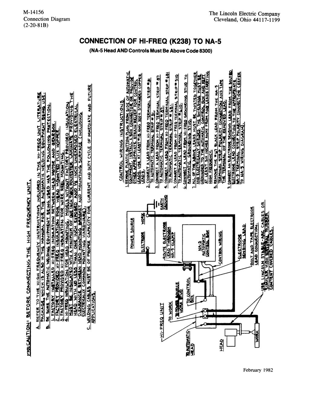
193
LT-7 Lightweight Tractor
 Operator s Manual LT-7 Lightweight Tractor For use with machines having Code Numbers: K395-2 Save for future reference Register your machine: www.lincolnelectric.com/register Authorized Service and Distributor
MAGNUM & MAGNUM PRO CURVE 300 & 400 GMA GUN and CABLE ASSEMBLY
 Operator s Manual MAGNUM & MAGNUM PRO CURVE 300 & 400 GMA GUN and CABLE ASSEMBLY Magnum For use with models: K470-[ ] K1802-1 K471-[ ] K2286-1 K541-[ ] K2951-[ ] K2952-[ ] K3055-[ ] Magnum PRO Curve Magnum
Stick/Mig Capability Welding Excellence Modular Construction Environment Protected 2,000 Watt AC Power for Tools
 E300 3+2 Electric Welder Service Manual Stick/Mig Capability Welding Excellence Modular Construction Environment Protected 2,000 Watt AC Power for Tools SVM_E300 3+2 SAFETY Arc Welding Safety Precautions
Magnum PRO. Guns. Operator s Manual. IM10009-C Issue D ate Dec-15 Lincoln Global, Inc. All Rights Reserved.
 Operator s Manual Magnum PRO Guns For use with machines having Code Numbers: 250 / 350 / 450 / 550 K2651-, K2652-, K2653-, and K2655- Magnum PRO 450 gun meets the following specification(s): IEC 60974-7:2013
OWNER S MANUAL. Affordable Tools Achieve More. MIG140. Visit Our Website at:
 Affordable Tools Achieve More Visit Our Website at: www.uwelding.com MIG140 OWNER S MANUAL Carefully read the operation manual prior to using, installing and maintaining the electric welding machine IMPORTANT
THE LINCOLN ELECTRIC COMPANY
 OPERATOR S MANUAL IM3050 04/2015 REV06 ENGLISH THE LINCOLN ELECTRIC COMPANY 22801 St. Clair Avenue Cleveland, OH 44117-1199 U.S.A. Phone: +1.216.481.8100 www.lincolnelectric.com English I English THANKS!
Operator s Manual Model AC300 ARC Welder
 Operator s Manual Model AC300 ARC Welder WARNING: Do not assemble, install, or operate this equipment without reading ALL of this manual and the safety precautions and warnings illustrated in this manual.
LT-7 TRACTOR TROUBLESHOOTING
 TROUBLESHOOTING IM279-TS JUNE 1995 Safety Depends on You Lincoln arc welding and cutting equipment is designed and built with safety in mind. However, your overall safety can be increased by proper installation...
THANK YOU FOR SELECTING A QUALITY PRODUCT BY LINCOLN ELECTRIC.
 THANK YOU FOR SELECTING A QUALITY PRODUCT BY LINCOLN ELECTRIC. PLEASE EXAMINE CARTON AND EQUIPMENT FOR DAMAGE IMMEDIATELY When this equipment is shipped, title passes to the purchaser upon receipt by the
INVERTER AIR PLASMA CUTTING MACHINE
 INVERTER AIR PLASMA CUTTING MACHINE OPERATION MANUAL DO NOT INSTALL, OPERATE OR MAINTAIN THIS MACHINE WITHOUT READING THIS MANUAL AND PLEASE ALWAYS THINK BEFORE YOU ACT. www.hyundaiwelding.com TECHNICAL
TURNING ROLLS 00338OG WARNINGS, SAFEGUARDS & OPERATING INSTRUCTIONS
 TURNING ROLLS 00338OG091207 WARNINGS, SAFEGUARDS & OPERATING INSTRUCTIONS Warnings and Safeguards for Welding and Cutting Operations IMPORTANT - Protect yourself and others! Remember that safety depends
LOTOS MIG175 MIG Welder
 LOTOS MIG175 MIG Welder TABLE OF CONTENTS SAFETY...... 3 SPECIFICATIONS... 8 General Description...8 What s Included.....8 Power Supply Ratings.....9 Machine Rear..10 Front Control Panel.10 Side Components...11
MIG Welders. Operator s Manual Model 135WFG Wire Feed Welder
 Operator s Manual Model 135WFG Wire Feed Welder MIG Welders WARNING: Do not assemble, install, or operate this equipment without reading ALL of this manual and the safety precautions and warnings illustrated
PRO Thru the Arm Robotic Torch - for AutoDrive S
 Operator s Manual Magnum PRO Thru the Arm Robotic Torch - for AutoDrive S Save for future reference Register your machine: www.lincolnelectric.com/registration Authorized Service and Distributor Locator:
Paralleling Arc Welding Power Sources
 004 859A 2005 10 Paralleling Arc Welding Power Sources Visit our website at www.millerwelds.com SECTION 1 SAFETY PRECAUTIONS - READ BEFORE USING Warning: Protect yourself and others from injury read and
Quick Draw Spool Gun OWNER S MANUAL
 Quick Draw Spool Gun OWNER S MANUAL WARNING: Read carefully and understand all ASSEMBLY AND OPERATION INSTRUCTIONS before operating. Failure to follow the safety rules and other basic safety precautions
COOL ARC 35. Operator s Manual. IM959 Issue D ate Oct- 13 Lincoln Global, Inc. All Rights Reserved.
 Operator s Manual COOL ARC 35 For use with machines having Code Numbers: 11427 Save for future reference Register your machine: www.lincolnelectric.com/register Authorized Service and Distributor Locator:
Loose Parts Note: Determine the left and right sides of the machine from the normal operating position.
 Brake Kit Dingo TX 0 & Compact Utility Loader Part No. 0 0 & 0 Loose Parts Note: Determine the left and right sides of the machine from the normal operating position. Description Qty. Use Drive wheel Brake
MAXSA 22 & 29 WIRE DRIVE
 Operator s Manual MAXSA 22 & 29 WIRE DRIVE For use with machines having Code Numbers: 11615, 11616, 11815, 11816 Save for future reference Register your machine: www.lincolnelectric.com/register Authorized
TCV400. Operator s Manual. IM10063-B Issue D ate Jul-17 Lincoln Global, Inc. All Rights Reserved.
 Operator s Manual For use with machines having Code Numbers: 11727, 11838 Save for future reference Register your machine: www.lincolnelectric.com/register Authorized Service and Distributor Locator: www.lincolnelectric.com/locator
OWNER S MANUAL. Affordable Tools Achieve More. LT3500. Visit Our Website at:
 Affordable Tools Achieve More Visit Our Website at: www.uwelding.com @lotostech LT3500 OWNER S MANUAL Carefully read the operation manual prior to using, Installing and maintaining the electric welding
RANGER 250 GXT (AU)Model
Model") Operator s Manual RANGER 250 GXT (AU)Model For use with machines having Code Numbers: 11689, 11741, 11796, 11803, 12099, 12194, 12205 Save for future reference Date Purchased Code: (ex: 10859) Register
Operator s Manual RANGER 250 GXT (AU)Model For use with machines having Code Numbers: 11689, 11741, 11796, 11803, 12099, 12194, 12205 Save for future reference Date Purchased Code: (ex: 10859) Register
POWER MIG (140, 180 MODELS)
") Operator s Manual POWER MIG (140, 180 MODELS) For use with machines having Code Numbers: 11254, 11255, 11256, 11257 and 11444 LINCOLN ELECTRIC Save for future reference Register your machine: www.lincolnelectric.com/register
Operator s Manual POWER MIG (140, 180 MODELS) For use with machines having Code Numbers: 11254, 11255, 11256, 11257 and 11444 LINCOLN ELECTRIC Save for future reference Register your machine: www.lincolnelectric.com/register
For use with machine Code POWERPLUS II 350 K POWERPLUS II 500 K
 IM7003-5 Otc, 2009 Rev. 1 POWERPLUS Ⅱ 350/500 For use with machine Code POWERPLUS II 350 K32063-1 POWERPLUS II 500 K32064-1 Safety Depends on You Lincoln arc welding and cutting equipment is designed and
LN-25 PRO. Operator s Manual. IM10076 Issue D ate Mar-18 Lincoln Global, Inc. All Rights Reserved.
 Operator s Manual LN-25 PRO For use with machines having Code Numbers: 11746, 11747 Save for future reference Date Purchased Code: (ex: 10859) Register your machine: www.lincolnelectric.com/register Authorized
DIGI-CUT 40PFC MV. Part No. 9030H OPERATOR S MANUAL
 DIGI-CUT 40PFC MV Part No. 9030H OPERATOR S MANUAL IMPORTANT Read this Owner s Manual completely before attempting to use this equipment. Save this manual and keep it handy for quick reference. Pay particular
MMWP125I OWNER S MANUAL
 MMWP125I OWNER S MANUAL 1/2017 WARNING: Read carefully and understand all ASSEMBLY AND OPERATION INSTRUCTIONS before operating. Failure to follow the safety rules and other basic safety precautions may
AutoDrive 4R220. Operator s Manual. IM945-C Issue D ate Oct-14 Lincoln Global, Inc. All Rights Reserved.
 Operator s Manual AutoDrive 4R220 For use with machines having Code Numbers: 455, 882, 956, 2273 Save for future reference Register your machine: www.lincolnelectric.com/register Authorized Service and
Mega Force 140i MP. Operator s Manual. IM10462 Issue D ate Apr-18 Lincoln Global, Inc. All Rights Reserved.
 Operator s Manual Mega Force 140i MP For use with Code Numbers: 12769 Save for future reference Date Purchased Code: (ex: 10859) Register your machine: www.lincolnelectric.com/register Authorized Service
MPPC40DVI OWNER S MANUAL
 MPPC40DVI OWNER S MANUAL 4/2017 WARNING: Read carefully and understand all ASSEMBLY AND OPERATION INSTRUCTIONS before operating. Failure to follow the safety rules and other basic safety precautions may
OPERATION INSTRUCTIONS
 www.r-techwelding.co.uk Email: sales@r-techwelding.co.uk Tel: 01452 733933 Fax: 01452 733939 ProArc 175 INVERTER ARC WELDER OPERATION INSTRUCTIONS Version 2017-10 2 3 Thank you for selecting the R-Tech
X-Tractor 1GC. Operator s Manual. IM576-B Issue D ate Apr-14 Lincoln Global, Inc. All Rights Reserved.
 Operator s Manual X-Tractor GC Save for future reference Register your machine: www.lincolnelectric.com/register Authorized Service and Distributor Locator: www.lincolnelectric.com/locator Date Purchased
Idealarc DC-600. Operator s Manual. IM642-E Issue D ate Oct-17 Lincoln Global, Inc. All Rights Reserved.
 Operator s Manual Idealarc DC-600 For use with machines having Code Numbers: 10588; 10589; 10590; 10591; 10592; 10593; 10594; 10595; 10596; 10639; 10640; 10641; 10700; 10701; 11071; 11072; 11129; 11130;
For use with machine Code POWERPLUS II 350 K / POWERPLUS II 500 K / 76097
 IM7003-1 April, 2011 Rev. 3 POWERPLUS Ⅱ 350/500 For use with machine Code POWERPLUS II 350 K60039-1 / 76095 POWERPLUS II 500 K60040-1 / 76097 Safety Depends on You Lincoln arc welding and cutting equipment
PC40 INVERTER PLASMA CUTTER 230V 40A SUM OWNER S MANUAL
 PC40 INVERTER PLASMA CUTTER 230V 40A SUM-900990 OWNER S MANUAL WARNING: Read carefully and understand all ASSEMBLY AND OPERATION INSTRUCTIONS before operating. Failure to follow the safety rules and other
MMW220PC OWNER S MANUAL
 MMW220PC OWNER S MANUAL 12/2015 WARNING: Read carefully and understand all ASSEMBLY AND OPERATION INSTRUCTIONS before operating. Failure to follow the safety rules and other basic safety precautions may
MMA 160S ARC/MMA WELDER OPERATION INSTRUCTIONS
 www.r-techwelding.co.uk MMA 160S ARC/MMA WELDER OPERATION INSTRUCTIONS 2 Thank you for selecting the R-Tech MMA160S Inverter Arc Welder. The MMA160S has many benefits over traditional Arc welders, including
QUATRO 450 OPERATOR S MANUAL
 QUATRO 450 OPERATOR S MANUAL IMPORTANT DO NOT INSTALL, OPERATE OR REPAIR THIS EQUIPMENT WITHOUT READING THIS MANUAL AND THE SAFETY SECTION CONTAINED INSIDE THIS MANUAL STARWELD WELDING SOLUTIONS WEBSITE:
SA-200-F163 (K6090-SM OR -SB)
") P-111-A RETURN TO MAIN INDEX P-111-A Shield-Arc SA-200-F163 (K6090-SM OR -SB) For Codes Below 7275, See P-23-A Model Index NUMBERS IN THE TABLE BELOW INDICATE WHICH COLUMN TO USE IN EACH PARTS LIST FOR
P-111-A RETURN TO MAIN INDEX P-111-A Shield-Arc SA-200-F163 (K6090-SM OR -SB) For Codes Below 7275, See P-23-A Model Index NUMBERS IN THE TABLE BELOW INDICATE WHICH COLUMN TO USE IN EACH PARTS LIST FOR
WELDING POSITIONER OPERATION MANUAL MODEL TT-100 V1.0
 WELDING POSITIONER OPERATION MANUAL MODEL TT-100 Carefully read and understand these operation instructions before operating, inspecting, or servicing this product. This manual for use with Serial Numbers
IDEALARC DC Operator s Manual. IM10214-A Issue D ate Oct-18 Lincoln Global, Inc. All Rights Reserved.
 Operator s Manual IDEALARC DC-500 For use with machines having Code Numbers: 2479 Save for future reference Date Purchased Code: (ex: 0859) Register your machine: www.lincolnelectric.com/register Authorized
Auto-Reamer. 2100E2 Nozzle Cleaning Station. Operating Manual and Parts List. January 2018 v18.1
 Auto-Reamer 2100E2 Nozzle Cleaning Station Operating Manual and Parts List 2100E2 w/ WC-95E DO NOT INSTALL, OPERATE, OR REPAIR THIS EQUIPMENT WITHOUT READING THIS OPERATING MANUAL MADE IN USA January 2018
MPPC60I OWNER S MANUAL
 MPPC60I OWNER S MANUAL 4/2017 WARNING: Read carefully and understand all ASSEMBLY AND OPERATION INSTRUCTIONS before operating. Failure to follow the safety rules and other basic safety precautions may
MIG/MAG-Welding Torch Push-Pull Plus
 T e c h n o l o g y f o r t h e W e l d e r s W o r l d. MIG/MAG-Welding Torch Push-Pull Plus The versatile torch, with the Plus The Features: Fits any commercially available wire drive unit by using a
MIG WELDER 131 ASSEMBLY AND OPERATING INSTRUCTIONS Mission Oaks Blvd., Camarillo, CA Visit our Web site at
 MIG WELDER 131 06098 ASSEMBLY AND OPERATING INSTRUCTIONS 3491 Mission Oaks Blvd., Camarillo, CA 93011 Visit our Web site at http://www.harborfreight.com Copyright 2003 by Harbor Freight Tools. All rights
OPERATION MANUAL M185. MIG/flux wire feeder welder. Serial Number: Where Purchase: Date of purchased:
 OPERATION MANUAL M185 MIG/flux wire feeder welder Serial Number: Where Purchase: Date of purchased: CONTENT 1. Safety... 2 2. Electrical principle drawing... 4 3. Specifications... 5 4. Front and rear
EH-10A. DIGITAL WELDING HEADS P/N s &
 INSTRUCTION MANUAL EH-10A DIGITAL WELDING HEADS P/N s 679774 & 558001535 F-12-873-C September, 2000 SPECIFICATIONS Motor - 110 volts, DC Permanent Magnet Continuous Operation @ 2.2 Amps DC. Gear Unit -
JM-160C,JM-175C, JM-180C, JM-200C
 wilkinsonstar.com MIG Series MIG/MAG/MMA Compact welding machines Order code! JM-160C,JM-175C, JM-180C, JM-200C OPERATOR MANUAL Your new product Thank you for selecting this Jasic Technology, Wilkinson
14 Lincoln Electric Bester Sp. z o.o. WELD PAK /95/CEE, 2004/108/CEE
 WELD PAK 2000 IM3051 04/2015 REV02 PŘÍRUČKA UŽIVATELE (OPERATOR S MANUAL IN ENGLI) ENGLISH Lincoln Electric Bester Sp. z o.o. ul. Jana III Sobieskiego 19A, 58-263 Bielawa, Poland www.lincolnelectric.eu
Water-Cooled Automatic Catalog 2008 LIT.9189 July, 2008
 Water-Cooled Automatic Water-Cooled Automatic Catalog 2008 LIT.9189 July, 2008 Technology for the Welder s World. TABLE OF CONTENTS AUT501D and AUT501DR Series, Water-Cooled AUT Gun w/ratings........3
PS MIG Volt MIG Welder Assembly & Operating Instructions
 PS07570 201205 MIG135 115 Volt MIG Welder Assembly & Operating Instructions READ ALL INSTRUCTIONS AND WARNINGS BEFORE USING THIS PRODUCT. This manual provides important information on proper operation
Cutlass Fasteners, Inc. 83 Vermont Ave., Unit 6, Warwick, RI Tel: (401) Fax: (401) cutlass-studwelding.com
 Fax: (401) cutlass-studwelding.com") MODEL : PHM-10 SHORT CYCLE WELD GUN PART NO. : PHM-10 SERIAL NO. : PLEASE READ THIS OPERATION AND MAINTENANCE MANUAL CAREFULLY BEFORE USING YOUR NEW CUTLASS STUD WELDER. COPYRIGHT CFI 2009 email: sales@
MODEL : PHM-10 SHORT CYCLE WELD GUN PART NO. : PHM-10 SERIAL NO. : PLEASE READ THIS OPERATION AND MAINTENANCE MANUAL CAREFULLY BEFORE USING YOUR NEW CUTLASS STUD WELDER. COPYRIGHT CFI 2009 email: sales@
PARTS LIST FOR LN-25 LN-25
 P-374 P-374 PARTS LIST FOR 200 250 300 350 400 450 500 550 600 650 700 100 150 50 IN IN/MIN WIRE FEED MORE T13086-99 1. 5. 4. 3. 2. IN/MIN. USED. cross. 35 31 23 25 27 29 15 17 19 21 P-374-A P-374-A ILLUSTRATION
Welding Clips. Model Due to continuing improvements, actual product may differ slightly from the product described herein.
 Welding Clips Model 95637 Assembly And Operation Instructions Due to continuing improvements, actual product may differ slightly from the product described herein. 3491 Mission Oaks Blvd., Camarillo, CA
Caddy. Tig 2200i AC/DC. Instruction manual GB Valid for: serial no. 711-, 747-xxx-xxxx
 Caddy Tig 2200i AC/DC Instruction manual 0460 225 301 GB 20180920 Valid for: serial no. 711-, 747-xxx-xxxx TABLE OF CONTENTS 1 SAFETY... 4 1.1 Meaning of symbols... 4 1.2 Safety precautions... 4 2 INTRODUCTION...
AIR VANTAGE 800 (AU) CUMMINS
 CUMMINS") Operator s Manual AIR VANTAGE 800 (AU) CUMMINS For use with machines having Code Numbers: 12557, 12762 Save for future reference Date Purchased Code: (ex: 10859) Register your machine: www.lincolnelectric.com/register
Operator s Manual AIR VANTAGE 800 (AU) CUMMINS For use with machines having Code Numbers: 12557, 12762 Save for future reference Date Purchased Code: (ex: 10859) Register your machine: www.lincolnelectric.com/register
IDEALARC DC Operator s Manual. IM10212 Issue D ate Sept-15 Lincoln Global, Inc. All Rights Reserved.
 Operator s Manual IDEALARC DC-000 For use with machines having Code Numbers: 80 Save for future reference Date Purchased Code: (ex: 0859) Register your machine: www.lincolnelectric.com/register Authorized
LF-72 PARTS LIST FOR RETURN TO MAIN INDEX
 Illustration of Sub Assemblies Illustration of Sub Assemblies Illustration of Sub Assemblies Illustration of Sub Assemblies P-501 RETURN TO MAIN INDEX PARTS LIST FOR P-501 P-501-A P-501-A ILLUSTRATION
PROPANE TORCH WITH TURBO BURNER
 PROPANE TORCH WITH TURBO BURNER MODEL 91894 ASSEMBLY AND OPERATING INSTRUCTIONS 3491 Mission Oaks Blvd., Camarillo, CA 93011 Visit our Web site at http://www.harborfreight.com TO PREVENT SERIOUS INJURY,
INSTRUCTION MANUAL FOR PLASMA CUTTER
 INSTRUCTION MANUAL FOR PLASMA CUTTER IMPORTANT: BEFORE STARTING THE EQUIP- MENT, READ THE CONTENTS OF THIS MANUAL, WHICH MUST BE STORED IN A PLACE FAMILIAR TO ALL USERS FOR THE ENTIRE OPERATIVE LIFE-SPAN
MIG 175. Item# OPERATOR S MANUAL
 MIG 175 Item# 164612 OPERATOR S MANUAL Read carefully and understand RULES FOR SAFE OPERATION and instructions before operating. Failure to follow the safety rules and other basic safety precautions may
Parts Catalog. Generator Set TGHAA (Spec A C) Printed in U.S.A. Replaces (Spec A) 1 97
 Printed in U.S.A. Replaces (Spec A) 1 97") Parts Catalog TGHAA Generator Set Printed in U.S.A. 9 00 (Spec A C) 9 Replaces 9 00 (Spec A) 97 To avoid errors or delay in filling your parts order, always give the MODEL, SPEC NO. and SERIAL NO. from
Parts Catalog TGHAA Generator Set Printed in U.S.A. 9 00 (Spec A C) 9 Replaces 9 00 (Spec A) 97 To avoid errors or delay in filling your parts order, always give the MODEL, SPEC NO. and SERIAL NO. from
SPEEDTEC 200C BR OPERATOR S MANUAL IM /2016 REV03 ENGLISH
 SPEEDTEC 200C BR OPERATOR S MANUAL IM3058 05/2016 REV03 ENGLISH Lincoln Electric Bester Sp. z o.o. ul. Jana III Sobieskiego 19A, 58-263 Bielawa, Poland www.lincolnelectric.eu 12/05 THANKS! For having chosen
OPERATION MANUAL MODELS TWE-250 TWE-321 TWE-375 TRU WELD EQUIPMENT COMPANY 6400 N. HONEYTOWN ROAD SMITHVILLE, OHIO (330)
") OPERATION MANUAL MODELS TWE-250 TWE-321 TWE-375 TRU WELD EQUIPMENT COMPANY 6400 N. HONEYTOWN ROAD SMITHVILLE, OHIO 44677 (330) 669 2773 CONTENTS Section Description Pages 1 Introduction 3 2 External Features
OPERATION MANUAL MODELS TWE-250 TWE-321 TWE-375 TRU WELD EQUIPMENT COMPANY 6400 N. HONEYTOWN ROAD SMITHVILLE, OHIO 44677 (330) 669 2773 CONTENTS Section Description Pages 1 Introduction 3 2 External Features
LN-25 TM PIPE. Operator s Manual. IM10092 Issue D ate 04/2011 Lincoln Global, Inc. All Rights Reserved.
 Operator s Manual LN-5 TM PIPE For use with machines having Code Numbers: 779 Save for future reference Register your machine: www.lincolnelectric.com/register Authorized Service and Distributor Locator:
Cutlass Fasteners, Inc. 83 Vermont Ave., Unit 6, Warwick, RI Tel: (401) Fax: (401) cutlass-studwelding.com
 Fax: (401) cutlass-studwelding.com") MODEL : BANTAM C8 BANTAM C10 PART NO. : 602-325A 602-343A SERIAL NO. : PLEASE READ THIS OPERATION AND MAINTENANCE MANUAL CAREFULLY BEFORE USING YOUR NEW CUTLASS STUD WELDER. COPYRIGHT CFI 2009 email: sales@
MODEL : BANTAM C8 BANTAM C10 PART NO. : 602-325A 602-343A SERIAL NO. : PLEASE READ THIS OPERATION AND MAINTENANCE MANUAL CAREFULLY BEFORE USING YOUR NEW CUTLASS STUD WELDER. COPYRIGHT CFI 2009 email: sales@
PRECISION TIG 375. Operator s Manual. IM898 Issue D ate Mar-17 Lincoln Global, Inc. All Rights Reserved.
 Operator s Manual PRECISION TIG 375 For use with machines having Code Numbers: 6, 6 Save for future reference Register your machine: www.lincolnelectric.com/register Authorized Service and Distributor
WELDING HELMET INSTRUCTIONS. Part #20520
 WELDING HELMET INSTRUCTIONS Part #20520 EASTWOOD WELDING HELMETS are specifically designed to provide maximum eye and face protection from harmful UV and IR radiation emitted when welding, in a lightweight,
Part #20279 MIG 250 WELDER ASSEMBLY & OPERATING INSTRUCTIONS
 Part #20279 MIG 250 WELDER ASSEMBLY & OPERATING INSTRUCTIONS PDF version available at eastwood.com/20279manual STATEMENT OF LIMITED WARRANTY The Eastwood Company (hereinafter Eastwood ) warrants to the
POWERTEC 205C, 255C & 305C
 POWERTEC 205C, 255C & 305C OPERATOR S MANUAL IM3021 09/2016 REV03 ENGLISH Lincoln Electric Bester Sp. z o.o. ul. Jana III Sobieskiego 19A, 58-263 Bielawa, Poland www.lincolnelectric.eu Declaration of conformity
Mig 4002c Mig 5002c Mig 6502c
 Origo Mig 4002c Mig 5002c Mig 6502c Instruction manual 0463 299 187 GB 20130924 Valid for: 946-xxx-xxxx, 947-xxx-xxxx, 948-xxx-xxxx TABLE OF CONTENTS 1 USER RESPONSIBILITY... 3 2 SAFETY PRECAUTIONS...
Cutlass Fasteners, Inc. 83 Vermont Ave., Unit 6, Warwick, RI Tel: (401) Fax: (401) cutlass-studwelding.com
 Fax: (401) cutlass-studwelding.com") MODEL : BANTAM C8 PART NO. : 602-325P SERIAL NO. : PLEASE READ THIS OPERATION AND MAINTENANCE MANUAL CAREFULLY BEFORE USING YOUR NEW CUTLASS STUD WELDER. COPYRIGHT CFI 2009 email: sales@ PAGE - 1 - WARRANTY
MODEL : BANTAM C8 PART NO. : 602-325P SERIAL NO. : PLEASE READ THIS OPERATION AND MAINTENANCE MANUAL CAREFULLY BEFORE USING YOUR NEW CUTLASS STUD WELDER. COPYRIGHT CFI 2009 email: sales@ PAGE - 1 - WARRANTY
Propane torch. Model Assembly And Operation Instructions
 Propane torch Model 39953 Assembly And Operation Instructions Due to continuing improvements, actual product may differ slightly from the product described herein. 3491 Mission Oaks Blvd., Camarillo, CA
Dimension OM A. Processes. Description. File: MULTIPROCESS. Multiprocess Welding. Arc Welding Power Source
 OM-272 476A 2015 09 Processes Multiprocess Welding Description Arc Welding Power Source Dimension 650 CE File: MULTIPROCESS Visit our website at www.millerwelds.com From Miller to You Thank you and congratulations
TEREX Woodsman 730 BRUSH CHIPPER
 Woodsman 730 BRUSH CHIPPER Parts Manual Customer Dealer S/N Frame # Date Woodsman 150 Commerce Drive, Farwell MI 486 Phone: (800) 953-553 Fax: (989) 588-487 Flipper Discharge Chute Hand Crank Belt Shield
MMWTIG241I OWNER S MANUAL
 MMWTIG241I OWNER S MANUAL WARNING: Read carefully and understand all ASSEMBLY AND OPERATION INSTRUCTIONS before operating. Failure to follow the safety rules and other basic safety precautions may result
PRECISION TIG 375. Operator s Manual. IM936-A Issue D ate Jun-16 Lincoln Global, Inc. All Rights Reserved.
 Operator s Manual For use with machines having Code Numbers: 11163 Save for future reference Register your machine: www.lincolnelectric.com/register Authorized Service and Distributor Locator: www.lincolnelectric.com/locator
THE GIANT-VAC PTO BLOWER MODELS 2000*/3200**/4000***
 THE GIANT-VAC PTO BLOWER MODELS 2000*/3200**/4000*** Congratulations! ASSEMBLY INSTRUCTIONS AND OPERATOR S MANUAL You have just purchased one of the finest pieces of outdoor power equipment on the market
XPS 350 And 450 CE OWNER S MANUAL OM A. Processes. Description Effective with serial number: MA284582D
 OM-249 332A 2010 07 Effective with serial number: MA284582D Processes MIG (GMAW) Welding Flux Cored (FCAW) Description Arc Welding Power Source XPS 350 And 450 CE www.millerwelds.com OWNER S MANUAL From
OPERATING MANUAL IDEALARC DC-600
 IMA 607A December 2005 OPERATING MANUAL IDEALARC DC-600 SAFETY DEPENDS ON YOU Lincoln Electric welders are designed and built with safety in mind. However, your overall safety can be increased by proper
OUTBACK 145. Operator s Manual. IM10073 Issue D ate 1/15 Lincoln Global, Inc. All Rights Reserved.
 Operator s Manual OUTBACK 145 For use with machines having Code Numbers: 11732 Save for future reference Date Purchased Code: (ex: 10859) Register your machine: www.lincolnelectric.com/register Authorized
Power Wave AC/DC 1000
 THE LINCOLN ELECTRIC COMPANY SUBMERGED ARC Power Wave AC/DC 1000 Increase ivity, Quality and Flexibility The Power Wave AC/DC 1000 is the first power source to introduce Waveform Control Technology to
Flextec 650X CE. Operator s Manual. IM10448 Issue D ate Mar-18 Lincoln Global, Inc. All Rights Reserved.
 Operator s Manual Flextec 650X CE For use with machines having Code Numbers: 2742 Save for future reference Date Purchased Register your machine: www.lincolnelectric.com/register Authorized Service and
XL12 Chain Saw UT Page 1 of 21 Carburetor Chamber
 XL12 Chain Saw UT-10080 Page 1 of 21 Carburetor Chamber XL12 Chain Saw UT-10080 Page 2 of 21 Carburetor Chamber 1 59274 1 GASKET- Spacer 2 59718 1 SPACER 3 63260A 1 RETAINER- Reed valve 4 63253 1 SEAT-
OPERATION MANUAL MODELS TWE-250 TWE-321 TWE-375 TRU WELD EQUIPMENT COMPANY 6400 N. HONEYTOWN ROAD SMITHVILLE, OHIO (330)
") OPERATION MANUAL MODELS TWE-250 TWE-321 TWE-375 TRU WELD EQUIPMENT COMPANY 6400 N. HONEYTOWN ROAD SMITHVILLE, OHIO 44677 (330) 669 2773 Version 1.3 Date 10/20/2010 TRU WELD EQUIPMENT LIMITED WARRANTY All
OPERATION MANUAL MODELS TWE-250 TWE-321 TWE-375 TRU WELD EQUIPMENT COMPANY 6400 N. HONEYTOWN ROAD SMITHVILLE, OHIO 44677 (330) 669 2773 Version 1.3 Date 10/20/2010 TRU WELD EQUIPMENT LIMITED WARRANTY All
VANTAGE 400 (CE) Operator s Manual. IM889-C Issue D ate July-14 Lincoln Global, Inc. All Rights Reserved.
 Operator s Manual. IM889-C Issue D ate July-14 Lincoln Global, Inc. All Rights Reserved.") Operator s Manual For use with machines having Code Numbers: 11296, 11297, 11463, 11464, 12195, 12308 Save for future reference Date Purchased Register your machine: www.lincolnelectric.com/register Authorized
Operator s Manual For use with machines having Code Numbers: 11296, 11297, 11463, 11464, 12195, 12308 Save for future reference Date Purchased Register your machine: www.lincolnelectric.com/register Authorized
1800 rpm Fuel Efficient Low Noise Level Welding Excellence 3000 Watt AC Generator. D300K3+3 Diesel Welder Service Manual
 D300K3+3 Diesel Welder Service Manual (with optional Wirefeed Module) 1800 rpm Fuel Efficient Low Noise Level Welding Excellence 3000 Watt AC Generator SVM_D300K3+3 SAFETY Arc Welding Safety Precautions
PRO6.4, PRO6.4E, PRO9.0, PRO9.0E Generator Service Manual
 PRO6.4, PRO6.4E, PRO9.0, PRO9.0E Generator Service Manual IMPORTANT: Read all safety precautions and instructions carefully before operating equipment. Ensure equipment is stopped and level before performing
MIG/Stick/TIG MP200iDV LCD 200 Amp
 MIG/Stick/TIG MP200iDV LCD 200 Amp Dual Voltage Multi-Process Welder Owner s Manual WARNING: Read carefully and understand all ASSEMBLY AND OPERATION INSTRUCTIONS before operating. Failure to follow the
JOHN DEERE WORLDWIDE COMMERCIAL & CONSUMER EQUIPMENT DIVISION. Lawn Tractors L100, L110, L120, and L130 TM2026 DECEMBER 2002 TECHNICAL MANUAL
 2026 December 2002 JOHN DEERE WORLDWIDE COMMERCIAL & CONSUMER EQUIPMENT DIVISION Lawn Tractors L100, L110, L120, and L130 TM2026 DECEMBER 2002 TECHNICAL MANUAL North American Version Litho in U.S.A. Safety
TP300 INDUSTRIAL TRASH PUMP OPERATOR S MANUAL
 TP300 INDUSTRIAL TRASH PUMP OPERATOR S MANUAL IT IS EXTREMELY IMPORTANT TO READ AND UNDERSTAND THE ENTIRE CONTENTS OF THIS OPERATOR S MANUAL BEFORE ATTEMPTING TO OPERATE THE PRODUCT. THIS EQUIPMENT IS
Package Contents Part A (3) I-Beam (1) Base (2) Other parts
 I-Beam (1) Base (2) Other parts") Page 1 Installation Instructions for 81245 Adjustable Height Gantry Crane 1-Ton Capacity Table of Contents Important Safety Information pg. 2 Specific Operation Warnings pg. 2 Main Parts of Product pg.
Page 1 Installation Instructions for 81245 Adjustable Height Gantry Crane 1-Ton Capacity Table of Contents Important Safety Information pg. 2 Specific Operation Warnings pg. 2 Main Parts of Product pg.
M-3025CB-AV Fuel Pump
 SAVE THESE INSTRUCTIONS M-3025CB-AV Fuel Pump Owner s Manual TABLE OF CONTENTS General Information... 2 Safety Instructions... 2 Installation... 3 Operation... 4 Maintenance... 4 Repair... 5 Troubleshooting...
SPEEDTEC 215C OPERATOR S MANUAL IM /2016 REV01 ENGLISH
 SPEEDTEC 215C IM3057 06/2016 REV01 OPERATOR S MANUAL ENGLISH Lincoln Electric Bester Sp. z o.o. ul. Jana III Sobieskiego 19A, 58-263 Bielawa, Poland www.lincolnelectric.eu Declaration of conformity Lincoln
ECSS. Electric Chain Saw Chain Sharpener Assembly & Operating Instructions
 ECSS Electric Chain Saw Chain Sharpener Assembly & Operating Instructions READ ALL INSTRUCTIONS AND WARNINGS BEFORE USING THIS PRODUCT. SAVE THESE INSTRUCTIONS FOR FUTURE REFERENCE. This manual provides
SPECIFICATIONS Horsepower: 1.5 HP Running Maximum PSI: 125 PSI Tank Capacity: 15 Gallons CFM: 6 40 PSI 5 90 PSI
 15 GALLON AIR COMPRESSOR Model: 7678 DO NOT RETURN TO STORE Please call 800-348-5004 for parts and service CALIFORNIA PROPOSITION 65 WARNING: You can create dust when you cut, sand, drill or grind materials
PLATFORM WELDER PACKAGE MANUAL
 PLATFORM WELDER PACKAGE MANUAL Part Number 0083991 March 2014 Replaces 0083991 March 2008 Additional Information For additional information contact your local dealer or Snorkel at: Snorkel International
Power MIG 350MP. Operator s Manual. IM10105 Issue D ate Jan-18 Lincoln Global, Inc. All Rights Reserved.
 Operator s Manual Power MIG 350MP For use with machines having Code Numbers: 87 Save for future reference Register your machine: www.lincolnelectric.com/register Authorized Service and Distributor Locator:
XTM353SW XTM403SW XTM-WF100 OPERATOR MANUAL ISSUE 1
 XTM353SW XTM403SW XTM-WF100 OPERATOR MANUAL ISSUE 1 Welcome Thank you and congratulations on choosing Parweld. This Owner s Manual is designed to help you get the most out of your Parweld products. Please
Voltmaster Centrifugal Trash Pumps
 Voltmaster Centrifugal Trash Pumps Model TSP2, TSP3 and TSP4 Owner s Manual February 2011 Table of Contents 1 Introduction............................ 1 1.1 Read before using..................... 1 1.2