RoomMaster ABR-2. Installation
|
|
|
- Darleen Higgins
- 6 years ago
- Views:
Transcription


1 Installation
2 List of contents General General... 3 Specification... 3 Accessories... 3 Dimensions and weight... 3 Delivery and transport... 4 Disassembling the unit... 4 Positioning the unit... 5 Reduced transport weight... 5 Safety regulations... 6 Electrical connection... 6 Combi-hood... 6 Ducts... 6 Condensation insulation of ducts... 7 Thermal insulation of ducts... 7 Damper - Risk of freezing... 7 Assembly - Damper... 7 Outdoor air damper for not prepared units... 7 Installation Alternative installations... 8 Connection at the rear... 8 Connection at the side... 8 Connection in a corner... 9 Variable distribution pattern Accessories Presence indicator Exhaust air connection Kit for modifying distribution pattern Carrying handle Connection box Combi-hood Outdoor air damper Interior panelling to ceiling Fläkt Woods 8059 GB Specifications are subject to alteration without further notice.
3 Safety information Important safety information Read carefully through the directions, advice and warning texts contained in the operating instructions before the room unit is installed and taken into service. The RoomMaster size 2 will then function in a satisfactory fashion and provide the greatest benefit. The unit must be operated by adults. Do not allow children to play with it or touch the controls. All installation work and interventions in the product must be performed by an authorized specialist. Work done by inadequately qualified persons may impair the function of the RoomMaster and cause damage to individuals and property. Servicing and repairs should be carried out by a service company approved by the supplier. Use only spare parts obtained from them. Make certain that the power supply cable is not trapped when installing or moving the unit. The unit is heavy. The risk of crushing injury is present when lifting or disassembling the unit. If necessary, use appropriate lifting accessories or other suitable equipment. Take care when moving the unit. The unit must be connected to ducts before it can be started up. Use protection gloves when installing the unit. If the unit is not to be installed directly after delivery, it should be kept under a roof with the packing still on. Fläkt Woods 8059 GB Specifications are subject to alteration without further notice.
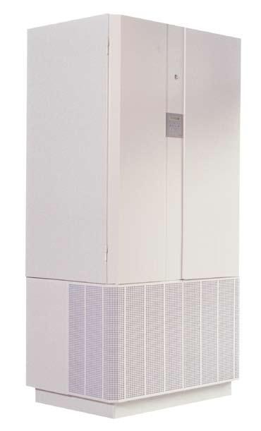
4 General, specification, dimensions and weights General RoomMaster is a complete air handling system with a supply air and exhaust air capability comprising a single ABR room unit with the necessary control and regulation equipment and an integral Floormaster terminal device. This is the new, simple approach to air handling in rooms in the same fire cell in schools, offices, conference rooms, shops, foyers/waiting rooms, leisure centres and production areas, etc. The purpose of the unit is to provide good ventilation of the premises with the least possible intervention. It is not allowed to install the unit in sanitary areas. The outdoor air is filtered, and a very considerable proportion of any heat in the exhaust air is transferred to the supply air in a rotary heat exchanger. The air is supplied to the premises via a displacement supply air terminal device, which allows the air to flow out slowly over the floor and to displace any heat and impurities towards the ceiling, from where they are led away as exhaust air. Dimensions and weight The principal dimensions of the unit can be seen in Fig Specification Room Unit ABR-a-b-c-d Size (a) 2 = standard flow 250 l/s Execution, rotor type (b) 1 = standard, non-hygroscopic rotor 750 Afterheater (c) 1 = electrical heater, 1 kw 100 Cooling coil (d) 0 = without 1 = cooling (water) ø 250 Accessories Combi-hood ABRZ Kit for modifying distribution pattern ABRZ Interior panelling to ceiling ABRZ-03-2 Presence indicator ABRZ-04-2 Fig. 1. Dimensions Exhaust air connection ABRZ-05-2 Outdoor air damper ABRZ-06-2 Weight Carrying handle, kit Replacement filter, kit ABRZ-07-2 ABRZ-08-2 Top (complete) Top (empty) Bottom, without cooling coil 203 kg 117 kg 68 kg Complete unit 270 kg Complete unit, incl. packaging 295 kg Fläkt Woods 8059 GB Specifications are subject to alteration without further notice.
5 Transport, disassembling the unit Delivery/transport The unit is supplied ready assembled on a pallet that is used for lifting and transport. Fläkt Woods recommend that the unit should be disassembled and emptied of components and also that lifting handles is used to facilitate transport to the installation site. Disassembling the unit 1. Make sure that the unit is dead by pulling out the plug. 2. Open the inspection doors, using the key supplied; see Fig Lift out the safety plate in front of the electrical compartment (1 in Fig. 2). First raise the plate, and then pull its lower edge out and down. 4. Disconnect the electric cable (2), which is connected to the right-hand door, from the control card. 5. Lift off both doors (3) from their hinges. 6. Disconnect the connector for the electric air heater (10), and pull it out complete with the dividing wall. 7. Disconnect the connector for the lower fan (11). 8. Unscrew the two hexagonal bolts (10 mm spanner) on the fan mounting flange, and pull it out. 9. Carefully pull up the electric cable (7) for the supply air sensor until the bulb (inserted in a cable shoe; see detailed drawing) comes up against the rubber grommet, and tape the cable securely to the bottom panel of the unit. N.B. If the unit is equipped with a cooling coil, the right-hand front grille (8) of the terminal device part must be removed (bolts at the top and bottom edges). Then disconnect the connector (9) for the three-core cable. 10. Release the retainers for the lower filter cassette (12) (by pulling out the red handles), and pull it outwards. 11. Undo the four hexagonal bolts (15 in Fig. 3) (13 mm spanner) located on the bottom of the upper part of the unit. 12. Unscrew the two recessed-head screws (16) which secure the connecting plate between the terminal device part and the unit part. The plate is located centrally at the front of the unit and also serves as an attachment for the front grille of the terminal device part. 13. Fix the lifting handles (17), if required (accessory), with M8 bolts. 14. Lift off the unit part from the terminal device part Fig. 2, Principle parts of the unit. 1. Safety plate for electrical compartment 2. Connector on control card 3. Door 4. Dividing wall 5. Fan (exhaust air) 6. Filter (supply air) 7. Cable for supply air sensor 8. Front grille of terminal device part 9. Cable connector for cooling coil control valve (located on the end wall in the bottom part) 10. Electric air heater 11. Fan (supply air) (concealed in the Figure) 12. Filter (exhaust air) 13. Connector for presence sensor 14. Power supply cable, length 2.6 m Fläkt Woods 8059 GB Specifications are subject to alteration without further notice.
6 Positioning the unit, safety Fig. 5 Bärare stående 3657A 5;3,2 ABR fig Fig. 3 Fig Hexagon bolts, 4-off 16. Recessed-head screws in connecting plate 17. Lifting handles, accessory If it is preferred to transport the unit part lying down, one of the lifting handles can be moved to the right-hand upper short side; see Figs. 3 and Rotary heat exchanger 19. Connector Reduced transport weight The weight can be further reduced other than by disassembling the unit. 1. Pull out the dividing wall (located between the fan and the filter). 2. Disconnect the connector for the upper fan (5). 3. Unscrew the two hexagonal bolts (10 mm spanner) on the fan mounting flange, and lift it out by the flange. N.B. Protect the heat exchanger from damage when dismantling the upper fan. 4. Release the retainers for the upper filter cassette (6) (by pulling out the red handles), and pull it outwards. 5. Disconnect the two connectors (19) on the heat exchanger. 6. Remove the heat exchanger unit (18) as a whole by lifting and pulling at the same time. Positioning the unit Position the unit against a wall or in a corner. Make sure that the unit is solidly attached to the wall and that it is placed on a flat surface to avoid it from falling over. A position close to an outside wall is preferable, as this gives a short ducting run. A free clearance of 0.8 m is required in front of the unit to permit the cover to be opened. Safety regulations A rating plate is attached to the plinth of the unit. A safety warning is given on the cover of the electrical control cabinet. The STOP operating position on the control panel is a secondary connection which does not isolate the unit from the mains supply when it is switched off. Opening the doors causes the safety cut-out to interrupt the power supply to the components in the unit. N.B. Pull out the plug to ensure that the unit is dead before starting work in the electrical control cabinet. The unit has EC approval. Fläkt Woods 8059 GB Specifications are subject to alteration without further notice.
7 Electrical connection, combi-hood, ducts, damper Electrical connection The unit is connected by means of a plug to a singlephase 230 V, 10 A earthed socket. The maximum power consumption of the unit is 1670 W with an electric after-heater. All internal wiring is done at the factory. If the standard electrical, control or regulation connection is modified, the plug must be removed and replaced with a permanent electrical connection. Wiring must be done by a qualified electrical contractor and in accordance with current regulations. Combi-hood An exterior wall hood for both outdoor air and exhaust air is available as an accessory for the unit. This prevents the possibility of a short-circuit between the two airflows by the exhaust air exiting from the hood at relatively high velocity, and the outdoor air being taken in level with the wall. The dimensions of the combi-hood are given in Fig. 6. The hood is made of black plastic-coated sheet metal. The front panel is detachable and can be rotated for left-hand or right-hand installation. Outdoor air must always be taken in from below. The two push-in connections have rubber seals and a Ø 250 mm connection. The hood is fixed to the wall by screwing or nailing. Sealing with the façade is necessary to prevent water from entering. Fig Ducts ø 250 The unit s sleeve couplings have a push-on dimension of 250 mm. Their position is shown in Fig. 7. With the rear surface of the unit against an exterior wall, it is possible to connect directly to the specially developed combi-hood, which is described elsewhere. The ducts are installed according to the following instructions so that they match the connections of the combi-hood. The ducts can naturally also be led directly through the roof. This is usually more expensive, and imposes a greater sealing requirement. The ducts are provided with 30 mm of external insulation with a waterproof outside surface (diffusion barrier). Note that this applies both to elbows on the unit and to ducts as far as outside walls. It must not be possible for room air to enter the insulation, resulting in the risk of condensation ø ø 250 Fig. 7. Duct connection upwards (part code d = 2). Condensation insulation of ducts The outdoor air and extract air duct transports cold air and must, therefore, always be provided with condensation insulation where the duct passes through a warm area. The ducts are provided with 30 mm of external insulation with a waterproof outside surface (vapour barrier). Note that this applies both to elbows on the unit and to ducts as far as walls. The ingress of room air into the insulation is associated with the risk of condensation of water vapour on the outside of the duct. Thermal insulation of ducts In order to safeguard the function and achieve high heat recovery, cold ducts such as those used for the outdoor air and extract air duct must be provided with additional insulation on top of the condensation insulation. This applies to places with a low outdoor temperature and when cladding is installed up to the ceiling. An exhaust air duct which passes through cold areas must always be insulated with at least 100 mm of external insulation. Damper - risk of freezing In order to be able to use the STOP operating mode, a damper with automatic closing is required in the exhaust air duct and a multi-louvre damper in the extract air duct. The absence of a damper will allow impurities to enter the unit by the back way, and the room and the unit will be cooled down during cold times of the year. Cooling of the room leads to increased heating costs and increases the risk of operating breakdowns with the unit. A unit with a water cooling coil (part code c = 2) must always be equipped with a damper if no anti-freeze is present in the cooling water. Fläkt Woods 8059 GB Specifications are subject to alteration without further notice.
8 Damper assembly, connection at the rear Damper assembly Outdoor air damper AB with actuator is designed for units prepared from the factory with transformer and steering components. The damper i ready to connect to the unit and suits both connections at the rear and at the top. The actuator has a supply air voltage of 24VAC controlled by a pressure switch. The outdoor air damper is supplied complete with damper unit and motor actuator with electrical connection. 6. Fit the combi-hood on the outside of the wall, directly in line with the holes, by screwing or nailing the hood to the wall as shown in Fig. 9. The joint with the wall above the combi-hood should be sealed with jointing compound. 7. Seal with foam between the unit and the wall. Outdoor air damper for not prepared units The damper can be installed in all versions of ABR-2. Mounting kit with transformer and pressure switch with cabling can be ordered separately. Foam or Skum eller insulation isolering Sealing Tätningsmassa compound Combi-hood Kombihuv Connection at the rear 1. Decide where the unit is to be positioned in the room. 2. Make holes for the ducts in the wall, as shown in Fig. 8. Note that the lateral dimension is measured from the proposed position of the unit. Fix Spikas with nails eller or skruvas screws 500 mm Fig. 9. Unit with connection at the rear viewed from the right-hand side. Min. ø285-max ø350 alt. 310x Fig. 8. Hole dimensions for alternative installations with duct connection at the rear 3. Now slide the unit into place. 4. Fit the straight duct elements from inside the room towards the connections in the combi-hood. 5. Fill the space between the ducts and the holes in the wall with insulation or foam. Fläkt Woods 8059 GB Specifications are subject to alteration without further notice.
9 Connection at the side, connection in a corner Connection at the side 1. Make a hole for the ducts in the wall, as shown in Fig. 10. Note that the dimensions are the same irrespective of the side from which duct connection takes place. 2. Position the unit against the wall. 3. Fit the duct elbows to the unit for each connection side, as shown in Figs. 11 or Fit the straight duct components inside the room towards the holes in the interior wall. At the same time, pass the cover plate loosely over the ducts. 5. Measure the ducts and cut to length flush with the exterior wall. 6. Fit the cover plate on the inside of the wall by fixing it with screws. 7. Then tape the joints between the duct elbows and the straight ducts, and those between the straight ducts and the cover plates; see Fig Fill the space between the ducts and the holes in the wall with insulation or foam, working from outside the wall. 9. Fit the combi-hood by first connecting it to the ducts from inside the room, and by then screwing or nailing the hood to the wall as shown in Fig. 13. The joint with the wall above the combi-hood should be sealed with jointing compound. Fig. 11. Duct routing to the left. Fig. 12. Duct routing to the right Ducts Kanaler can kapas be jäms extended up med to yttervägg ceiling level Täckplåt Cover plate Kanaler Cut ducts kan flush förlängas with Sealing Tätningsmassa upp exterior compound till taknivå wall Tejp Tape Combihood Kombihuv Isolering Insulation or eller skum foam Fix Spikas with nails eller or screws skruvas min 2510 min 2510 Min. ø 285 Max. ø 350 alt. 310 x 680 Fig. 13. Duct routing to the right. Unit viewed from the front. Connection in a corner See installation alternative, Connection to the side, for details of holes, insulation and fixing of combi-hood. Fig. 10. Hole dimensions for installation with duct connection to the side, Fig. 14. Connection in a corner, upwards. Fläkt Woods 8059 GB Specifications are subject to alteration without further notice.
10 Variable distribution pattern Variable distribution pattern The distribution pattern from the supply air terminal device can be changed to avoid problems with draughts, for example when repositioning furniture. The normal distribution pattern can be seen from Fig. 17. The broad distribution pattern, shown in Fig. 18, is obtained with the help of an accessory kit fitted on the inside of the front diffuser mat, as shown in Fig. 19. The cover strips are pressed firmly against the front diffuser mat by hand. An intermediate pattern can be achieved if only the wide cover strip is fitted. ABR Fig. 17. Normal distribution patter. Fig. 15. Duct connection to the rear. ABR Fig. 18. Broad distribution pattern (1104) Fig. 19. Installation of cover strip accessory kit. Fig. 16. Duct connection to the side. Fläkt Woods 8059 GB Specifications are subject to alteration without further notice.
11 Accessories Combi-hood ABRZ-01-2 Presence indicator AB Närvarogivare Presence sensor Instructions on page 7. Kit for modifying distribution pattern ABRZ-02-2 Exhaust air connection AB Grille Galler Damper Spjällenhet unit Exhaust air from Frånluft från adjoining angränsande rooms rum Fästram med stosar dim 125 Mounting frame with sleeves Installation instructions can be found under the heading, "Variable distribution pattern", on page 10. Damper Spjällåsning locking Interior panelling to ceiling AB Outdoor air damper AB See separate instructions. Carrying handle AB See separate instructions. Fitting instructions on pages 5 and 6, and in Figs. 3 and 4. Fläkt Woods 8059 GB Specifications are subject to alteration without further notice.
12 FWG_AHU_ABR2 Technical instruction_ _se_8059 Condesign Info Productions AB ABF5533 Fläkt Woods AB Jönköping t f w
ECONOVENT PUM Installation and maintenance instructions for rotary heat exchangers
 Plant: Heat exchanger designation: ECONOVENT PUM Installation and maintenance instructions for rotary heat exchangers Contents Design, Condition on delivery........................................3 Handling,
Rotary heat exchanger EURA split rotor, sizes 50 53
 Delivery units Sizes 50 53 are always supplied as two delivery units with a split rotor; see Fig. 2. Measurement nipples 1835 Fig. 1 Fig. 2 Dimensions and weights 3348 ø D Service access space D/2 Lifting
PUM(O,R,V) AND PUML INSTALLATION AND MAINTENANCE INSTRUCTIONS FOR ROTARY HEAT EXCHANGERS ROTOR SIZE (460/500)
 AND PUML INSTALLATION AND MAINTENANCE INSTRUCTIONS FOR ROTARY HEAT EXCHANGERS ROTOR SIZE (460/500)") PUM(O,R,V) AND PUML INSTALLATION AND MAINTENANCE INSTRUCTIONS FOR ROTARY HEAT EXCHANGERS ROTOR SIZE 060 420 (460/500) 2 Installation and maintenance Content Page 1. Description - Unit design... 3 2. Handling
PUM(O,R,V) AND PUML INSTALLATION AND MAINTENANCE INSTRUCTIONS FOR ROTARY HEAT EXCHANGERS ROTOR SIZE 060 420 (460/500) 2 Installation and maintenance Content Page 1. Description - Unit design... 3 2. Handling
TECHNICAL DOCUMENTATION WOLF AIR HEATERS LH-EC / LH. 30m 3 /h
 TECHNICAL DOCUMENTATION WOLF AIR HEATERS LH-EC / LH 30m 3 /h THE EXTENSIVE EQUIPMENT RANGE from system supplier WOLF offers the ideal solution for commercial and industrial buildings, new build and modernisation
INSTALLATION, OPERATION AND MAINTENANCE TECHNICAL MANUAL
 ISO 9001:2008 Via Renata Bianchi, 12 16152 Genova ITALY Tel. +39.01.6017016 Fax. +39-010-601-6021 www.tecnidro.com s INDEX 1. Introduction 1.1 Premise 1.2 Generality 1.3 Principle of operation 2. INSTALLATION
Vent-Axia Roof Units Range Energy Recovery Ventilation (ERV) Range
 Range") CI/SfB (57.7) 1st Edition from Vent-Axia Vent-Axia Roof Units Range Energy Recovery Ventilation (ERV) Range Energy Recovery Ventilation (ERV) Range Building on the success of the Sentinel Totus 2 range
CI/SfB (57.7) 1st Edition from Vent-Axia Vent-Axia Roof Units Range Energy Recovery Ventilation (ERV) Range Energy Recovery Ventilation (ERV) Range Building on the success of the Sentinel Totus 2 range
CHAPTER 21 ENVIRONMENT CONTROL. Section Title Page
 CHAPTER 21 ENVIRONMENT CONTROL Section Title Page 21-00 Description........................................ 21.1 21-10 Ventilation........................................ 21.3 21-11 Nose Vent................................
INSTALLATION, OPERATION & MAINTENANCE INSTRATIONS
 INSTALLATION, OPERATION & MAINTENANCE INSTRATIONS (27/6/13) Contents 1. GENERAL DESCRIPTION... 2 2. RECEIPT AND PREPARATION... 2 3. INSTALLATION... 2 3.1. REMOVAL OF ACCESS PANEL... 2 3.2. FIXING A PLINTH...
Warning. Document ref: A October 2015
 Sentry Door Curtain Installation, Operation & Maintainance Instructions Dunham-Bush Ltd, Downley Road, Havant, Hampshire, P09 2JD Tel. 023 9247 7700 Email. info@dunham-bush.co.uk Document ref: 128-000-001-A
PRODUCT BROCHURE. Rectangular Displacement Diffuser RDW-FD RDW-FD : smartemp.com
 PRODUCT BROCHURE Rectangular Displacement Diffuser RDW-FD smartemp.com DESCRIPTION The SMARTEMP Rectangular Displacement Diffuser, type RDW-FD (figure 1), produces a low velocity horizontal airflow pattern
C O L M A N. Air Distribution LINEAR SLOT DIFFUSERS CE SERIES SERIES
 C O L M A N Air Distribution E N G I N E E R E D A I R P R O D U C T S LINEAR SLOT DIFFUSERS CE SERIES CE SERIES LINEAR SLOT DIFFUSERS CE SERIES QUALITY AND EFFICIENCY WITHOUT COMPROMISE Application Colman
Swegon PACIFIC. Integrated climate beam
 Swegon Integrated climate beam www.eurovent-certification.com www.certiflash.com climate beam The is a high performance climate beam for installation in false ceilings. With high built-in flexibility,
Part No: Genuine Mira Accessories
 Bar Valve Fixing Kit Part No: 1663.017 Genuine Mira Accessories 1 Introduction Please take time to read this guide thoroughly, having done so, keep it handy for future reference. This Fixing Kit has been
GE Monogram. Installation. Instructions. Professional Vent Hoods. 48" Models ZV881WSS, ZV891YSS ZV880WSS, ZV890YSS. 36" Models ZV671WSS, ZV681YSS
 GE Monogram Installation Instructions Professional Vent Hoods 48" Models ZV881WSS, ZV891YSS ZV880WSS, ZV890YSS 36" Models ZV671WSS, ZV681YSS ZV670WSS, ZV680YSS 30" Models ZV370YSS, ZV371YSS CAUTION WARNING
EULR Fan. Fläkt Woods 8192 GB Specifications are subject to alteration without notice
 Page Installation..................2 Installation alternatives..........2 Connection to the inlet/outlet duct..3 Connection of duct to the fan outlet..3 Electrical connections...........3 Guards.....................4
HR25 Solo. Installation and User Instructions. Through the Wall Heat Recovery Ventilators
 abc GB HR25 Solo Installation and User Instructions Models:- HR25 Solo HR25 Solo L HR25 Solo H HR25 Solo LH Through the Wall Heat Recovery Ventilators PLEASE READ INSTRUCTIONS IN CONJUNCTION WITH ILLUSTRATIONS.
C O L M A N. Air Distribution JET DIFFUSERS DCJ SERIES DCJ SERIES
 C O L M A N Air Distribution E N G I N E E R E D A I R P R O D U C T S JET DIFFUSERS DCJ SERIES DCJ SERIES DCJ SERIES JET DIFFUSERS Application Colman s DCJ jet diffuser has been designed to supply cooled
Silent centrifugal air heater hot water supply
 Large range : 5 to 120 Flows : 900 to 14000 m 3 /h Numerous accessories Design integrating perfectly in public buildings USE Operation in zones ES and S Extra silent and silent Forced air heating for premises
Supply air unit DYBA. Specifications. Connbox. Quick Selection DYBA, without slot, 1:3 plenum box ATTC (50 Pa)
") DYBA is a quiet, ceiling-mounted supply air unit that consists of a nozzle diffuser, DYBH, and an insulated plenum box, ATTC. The nozzles of the diffuser produce a swirl pattern, which provides a highly
DYBA is a quiet, ceiling-mounted supply air unit that consists of a nozzle diffuser, DYBH, and an insulated plenum box, ATTC. The nozzles of the diffuser produce a swirl pattern, which provides a highly
LINEAR BAR GRILLES T SERIES. Quality and e!ciency without compromise
 LINEAR BAR GRILLES T SERIES Quality and e!ciency without compromise Weltech Business Centre - Ridgeway - Welwyn Garden City - Hertfordshire AL7 2AA Tel: 01707 871526 - Fax: 01707 871 527 - email sales@jprservices.co.uk
ROOFMASTER STEF ROOF FAN
 Air Comfort Air movement Roof fans ROOFMASTER STEF ROOF FAN» Technical CATALOGuE Contents ROOFMASTER STEF...3 Performance Data...4 Performance Table...6 General description...8 Fan Chart-explanation and
Swegon PACIFIC. Integrated climate beam QUICK FACTS KEY FIGURES
 Swegon PACIFIC Integrated climate beam QUICK FACTS The PACIFIC is a high performance climate beam for installation in false ceilings. With high built-in flexibility, it is designed to meet today s needs
Swegon PACIFIC. Integrated climate beam
 Swegon Integrated climate beam www.eurovent-certification.com www.certiflash.com climate beam The is a high performance climate beam for installation in false ceilings. With high built-in flexibility,
INSTRUCTION MANUAL MAGNA RAIL
 R ENGLISH NR. 148293 00 INSTRUCTION MANUAL MAGNA RAIL 1999-05-01 List of contents Declaration of conformity, CE Delivery check Mounting instruction (rail, trolley units) Mounting instruction (exhaust pipe,
VEM motors Thurm GmbH
 VEM motors Thurm GmbH Installation, Operating and Maintenance Instructions Single-Phase Squirrel-Cage Induction Motors, Standard Version March 2005 1. General To avoid damage to the motors and equipment
Locks and Catches Information
 Information SYMO 3000 is the worldwide unique furniture locking system from Häfele. Without tools and time-consuming installation, it provides maximum flexibility at minimum expenditure and effort. The
XeteX, Inc. All Rights Reserved.
 Model XC Indoor or outdoor mounted, simple, in-case aluminum flat plate exchanger with options for frost control. Ideal for inline installations: in duct-work systems, in built-up units, or in modular
Adriatic for individually suspended installation Exposed active climate beam with cooling, heating and ventilation
 Adriatic for individually suspended installation Exposed active climate beam with cooling, heating and ventilation ADRIATIC VF Climate beam Adriatic Adriatic is an enclosed climate beam with integrated
A E. P.M.G. range. Low Voltage Alternators - 4 pole. Installation and maintenance
 A E This manual concerns the P.M.G. alternator which which you you have have just just purchased. We wish to draw your attention to the contents of this maintenance manual. SAFETY MEASURES Before using
GigaBox centrifugal fans Product specific information
 GigaBox centrifugal fans Product specific information GigaBox and accessories Wall bracket GB-WK (ccessories) Outdoor cover hood GB-WSD (ccessories) Included in delivery: a) Flexible sleeve b) Outlet spigot,
C O L M A N. Air Distribution PERFORATED FACE DIFFUSERS P SERIES SERIES
 C O L M A N Air Distribution E N G I N E E R E D A I R P R O D U C T S PERFORATED FACE DIFFUSERS P SERIES P SERIES PERFORATED FACE DIFFUSERS P SERIES QUALITY AND EFFICIENCY WITHOUT COMPROMISE Application:
SCHÄFER IT-Systems The specialists for IT infrastructure
 SCHÄFER IT-Systems The specialists for IT infrastructure www.schaefer-it-systems.com 1 2 SCHÄFER IT-Systems The specialists for IT infrastructure SCHÄFER IT-Systems The specialists for IT infrastructure
ROOF FAN ROOFMASTER STEC
 AIR COMFORT AIR MOVEMENT ROOF FANS ROOF FAN ROOFMASTER STEC INSULATED VERSION» TECHNICAL CATALOGUE 2 STEC Roofmaster - Technical Catalogue CONTENTS GENERAL DESCRIPTION Application/specification... 3 Features...
C O L M A N. Air Distribution LINEAR BAR GRILLES T SERIES SERIES
 C O L M A N Air Distribution E N G I N E E R E D A I R P R O D U C T S LINEAR BAR GRILLES T SERIES T SERIES C O L M A N Air Distribution E N G I N E E R E D A I R P R O D U C T S LINEAR BAR GRILLES T SERIES
IN-LINE DUCT FANS MIXVENT-TD Fan Systems
 IN-LINE DUCT FANS MIXVENT-TD Fan Systems NEW TD-EXTRACTOR KIT (see page 175) MIXVENT TD / MIXVENT TD-T MIXVENT TDx2 ACCESSORIES Description Range Construction The MIXVENT system has been designed to compliment
1/11 29/06/2016 CONTENTS 1. GENERAL DUCTS, AIR VENTS, VALVES MONOBLOCK UNITS FILTRATION CONTROL...
 1/11 29/06/2016 VENTILATION AND Buildings & Technical Services Section AIR-CONDITIONING STANDARD CONTENTS 1. GENERAL... 2 2. DUCTS, AIR VENTS, VALVES... 2 3. MONOBLOCK UNITS... 3 4. FILTRATION... 5 5.
KWT GALLEY WATER WASH HOOD GALLEY WATER WASH HOOD KWT. With supply air and Capture Jet technology
 KWT GALLEY WATER WASH HOOD With supply air and Capture Jet technology APPLICATIONS Halton KWT is a galley water wash hood for use in marine & offshore applications. The highly efficient KWT hood uses Halton
ECONOVENT PUR (C) Installation and Maintenance Instruction
 Installation and Maintenance Instruction") ECONOVENT PUR (C) Installation and Maintenance Instruction Installation and Maintenance Instruction PUR (C) Contents Delivery Version of PUR (C)...3 Lifting PUR (C)...5 Assembling PUR (C)...6 Handling,
ECONOVENT PUR (C) Installation and Maintenance Instruction Installation and Maintenance Instruction PUR (C) Contents Delivery Version of PUR (C)...3 Lifting PUR (C)...5 Assembling PUR (C)...6 Handling,
HRE 350 & HRE 350B. Heat Recovery Unit. Installation and User Instructions. 230V~50Hz
 abc GB HRE 350 & HRE 350B Heat Recovery Unit Installation and User Instructions 230V~50Hz PLEASE READ INSTRUCTIONS IN CONJUNCTION WITH ILLUSTRATIONS. PLEASE SAVE THESE INSTRUCTION Installation and User
TKS-5001, TKS , TKS-6001, TKS-7001
 TAC 1354 Clifford Avenue P. O. Box 2940 Loves Park, IL 61132-2940 www.tac.com TKS-5001, TKS-5001-600, TKS-6001, TKS-7001 Pneumatic Temperature Transmitters Room General Instructions GENERAL INFORMATION
Floor Swirls Models BZD and SZD
 July 09 Floor Swirls Floor Swirls Models BZD and SZD Features Model BZD Circular Floor Swirl Model SZD Circular Step Diffuser Grilles Diffusers Louvres Chilled Beams Ruskin Air Management Limited www.ruskinuk.co.uk
Flue installation instructions. Air flue duct for use with ecomax and ecotec boilers. For the installer
 834449_05GB_022005.qd 02.02.2005 17:12 Uhr Seite 1 For the installer Flue installation instructions Air flue duct for use with ecomax and ecotec boilers ecomax 613/2 E ecomax 618/2 E ecomax 622/2 E ecomax
Halton Rex 600 RE6 - Adaptable active chilled beam
 Halton Rex 600 RE6 - Adaptable active chilled beam Halton Rex 600 chilled beam is: Combined cooling, heating, and supply air unit for flush installation within a suspended ceiling. Well suited for spaces
Motorized Fire Dampers
 Model : OMFD-611 (Fusible link and spring return actuator) GI steel sheet construction In accordance with UL555 & UL555S suitable for installation in walls and partitions having rating 2 Hrs. Static and
TD-MIXVENT Series IN-LINE MIXED FLOW DUCT FANS TD-MIXVENT. In-Line duct fans
 IN-LINE MIXED FLOW DUCT FANS Series Range of low profile in-line mixed flow duct fans manufactured in tough reinforced plastic (from 160 to 800 models) or with metal casing steel finished in a tough epoxy-polyester
Operating and Installation Instructions Diaphragm Vacuum Pumps and Compressors
 Operating and Installation Instructions Diaphragm Vacuum Pumps and Compressors Type range: UN813.3ANI UN813.4ANI UN813.3ANDCB UN813.4ANDCB UN813.5ANI Fig. 1: UN813.3ANI Fig. 2: UN813.4ANI You have selected
CH5000 Heat Recovery Ventilator
 ADVANCED COMMERCIAL Heat Recovery Ventilator PRODUCT SPECIFICATIONS & TECHNICAL DATA Features NOMINAL CAPACITY 3500-5500 CFM CASING Double-wall cabinet White exterior paint, 22-gauge galvanized steel -gauge
Fan coil unit NBS 100/150
 Fan coil unit /150 Ferdinand Schad KG Steigstraße 25-27 D-78600 Kolbingen Telephone +49 (0) 74 63-980 - 0 Fax +49 (0) 74 63-980 - 200 info@schako.de www.schako.de Contents Description...3 Advantages...3
C O L M A N. Air Distribution SWIRL DIFFUSERS DWT SERIES DWT SERIES
 C O L M A N Air Distribution E N G I N E E R E D A I R P R O D U C T S SWIRL DIFFUSERS DWT SERIES DWT SERIES DISTRIBUTION PATTERNS & FIXING OPTIONS Application The DWT Series of swirl diffusers have been
Composite PEX-AL-PEX Tubing
 04/01/11 page 1.1 Composite PEX-AL-PEX Tubing List Per Foot 40190F ½ Composite Tubing x 200.62 40190 ½ Composite Tubing x 250.62 40190A ½ Composite Tubing x 300.62 40190B ½ Composite Tubing x 1000.62 40192
IN-LINE MIXED FLOW DUCT FANS MIXVENT-TD Fan Systems
 IN-LINE MIXED FLOW DUCT FANS MIXVENT-TD Fan Systems MIXVENT TD / MIXVENT TD-T MIXVENT TDx2 ACCESSORIES Description Range Construction The MIXVENT system has been designed to compliment the MIXVENT-TD range
Rotary heat exchanger EURA, 20 53
 Rotary heat exchanger EURA, 0 5 Fig. Adjustment At a constant speed, check that the rotor is rotating in the right direction. The direction of rotation is indicated on the casing. If the purging sector
ECONET Fault and error manual
 Fault and error manual March 2009 Contents Basic data to get started...3 A Alarms 1. Ice alarm, GT 42...4 2. Frost alarm, GT 41...4 3. Pump alarm, P 40...5 4. Pressure alarm, GP 40...5 5. Liquid, temperature
Komfot (EC) SB v5(6) INSTALLATION GUIDE HEAT RECOVERY AND HEAT AND HUMIDITY RECOVERY AIR HANDLING UNIT
 SB v5(6) INSTALLATION GUIDE HEAT RECOVERY AND HEAT AND HUMIDITY RECOVERY AIR HANDLING UNIT") INSTALLATION GUIDE HEAT RECOVERY AND HEAT AND HUMIDITY RECOVERY AIR HANDLING UNIT KOMFORT EC S S11 SERIES KOMFORT EC SB S11 SERIES KOMFORT EC SB-E S11 SERIES KOMFORT EC SB-E S11 SERIES Tools required Pencil
INSTALLATION GUIDE HEAT RECOVERY AND HEAT AND HUMIDITY RECOVERY AIR HANDLING UNIT KOMFORT EC S S11 SERIES KOMFORT EC SB S11 SERIES KOMFORT EC SB-E S11 SERIES KOMFORT EC SB-E S11 SERIES Tools required Pencil
INSTALLATION INSTRUCTIONS
 MiniCOREVentilator ENERGY RECOVERY CORE INSTALLATION INSTRUCTIONS MC500-1ERV JANUARY 10, 2018 SUPERSEDES: NONE INSTALLATION INSTRUCTIONS FOR MINICORE VENTILATOR (MCV) WITH FACTORY INSTALLED OPTIONS USED
SUBSTATION VACUUM CIRCUIT BREAKER (15.5KV)
") SUBSTATION VACUUM CIRCUIT BREAKER (15.5KV) For more than four decades, Myers Power Products has led the switchgear market in quality for the electric industry, delivering highly reliable products for utilities
SUBSTATION VACUUM CIRCUIT BREAKER (15.5KV) For more than four decades, Myers Power Products has led the switchgear market in quality for the electric industry, delivering highly reliable products for utilities
SUBSTATION VACUUM CIRCUIT BREAKER (38KV)
") SUBSTATION VACUUM CIRCUIT BREAKER (38KV) For more than four decades, Myers Power Products has led the switchgear market in quality for the electric industry, delivering highly reliable products for utilities
SUBSTATION VACUUM CIRCUIT BREAKER (38KV) For more than four decades, Myers Power Products has led the switchgear market in quality for the electric industry, delivering highly reliable products for utilities
SUBSTATION VACUUM CIRCUIT BREAKER (25.8 / 27KV)
") SUBSTATION VACUUM CIRCUIT BREAKER (25.8 / 27KV) For more than four decades, Myers Power Products has led the switchgear market in quality for the electric industry, delivering highly reliable products
SUBSTATION VACUUM CIRCUIT BREAKER (25.8 / 27KV) For more than four decades, Myers Power Products has led the switchgear market in quality for the electric industry, delivering highly reliable products
Ceiling swirl diffusers
 X X testregistrierung Ceiling swirl diffusers Type Horizontal swirling air discharge Adjustable blades Protective cage For high rooms, with adjustable air control blades Circular ceiling swirl diffusers,
TO BE USED ONLY BY AUTHORISED PERSONNEL
 SERVICE MANUAL for BOSTON (MG 3000 STD) SANTA FE (CALGARY, MG 3000 FLS) & ODESSA (PG 3000) GAS FIRES TO BE USED ONLY BY AUTHORISED PERSONNEL PART No 588402 Issue E Nov. 2001 CONTENTS TROUBLESHOOTING Page
Air Handling Units. Geniox. Accessories
 Air Handling Units Geniox Accessories The right accessories are important to optimise your Geniox air handling unit to the task at hand. SystemairCAD provides you with a wide selection of accessories.
11. Installation Instruction
 11. Installation Instruction 11.1 Select The Best Location If an awning is built over the unit to prevent direct sunlight or rain, be careful that heat radiation from the condenser is not obstructed. There
RERV & RERVX RERVLP. Rotary Energy Recovery Ventilators. Low Profile Indoor Rotary Energy Recovery Ventilators
 Version: Dec. 01, 2004 RERV & RERVX Rotary Energy Recovery Ventilators Indoor and Outdoor Installations 250 20,000 CFM Capacities RERVLP Low Profile Indoor Rotary Energy Recovery Ventilators Ideal for
Submittal Data PERFORMANCE DATA CERTIFIED DIMENSION PRINTS CERTIFIED ROOF CURB DIMENSION PRINTS SERVICE OPTION DIMENSION PRINTS
 50Hz Single Package Rooftop, Cooling Only with Puronr (R---410A) Refrigerant One Stage Cooling Capacity Control: Size 07 Two Stage Cooling Capacity Control: Sizes 08, 09, 12 & 14 Submittal Data PERFORMANCE
CURVED CC5 CC5 RF6 CC5 RF9 CC5 RF12 CC5 RF15 CC5 HT6 CC5 HT9 CC5 HT12. Page 1. Download C.A.D models or contact us on COSSIGA.COM
 CURVED CC5 RF CC5 RF6 CC5 RF9 CC5 RF12 CC5 RF15 Deck forced refrigeration Sliding doors front and rear Double glazed Two adjustable shelves Ticket strips on shelves and deck Undershelf and canopy LED lights
ACCESSORIES FOR SZE2 CABINETS
 ZPAS 143 DOORS Doors Intended for use instead of front solid door or rear panel. Maximum door opening angle: 120 Sheet steel textured powder paint, light grey (RAL 7035), stiffened profiles, brown smoked
AIR-TO-AIR HEAT EXCHANGERS MODEL Q2 TECHNICAL SPECIFICATION
 AIR-TO-AIR HEAT EXCHANGERS MODEL Q2 TECHNICAL SPECIFICATION ADDRESS AND CONTACT DATA Heatex AB Bronsyxegatan 13 S-213 75 MALMÖ Sweden Telephone: +46 410 710 500 info@heatex.com www.heatex.com DISCLAIMER
Fuel Filter Unit P/n. RR002
 Fuel Filter Unit P/n. RR002 Owner s Manual Page 1/9 General Info: Total Weight (filter incl.): 310 g / 0.683 Lbs Max Operating Pressure: 0.7 MPa / 101 PSI Stainless Steel Filter Mesh: 50 Fuel Inlet Threading:
MODEL E REPAIR KIT INSTALLATION INSTRUCTIONS
 1 Under normal conditions, installation of a complete RK-E kit should be necessary only at time of major engine overhaul or when converter has been out of service for some time. Gaskets and diaphragms
ADAPTTM. Free. Active communicative, supply air diffuser for the WISE system, ADAPT F
 ADAPTTM Free Active communicative, supply air diffuser for the WISE system, ADAPT F Quick facts Supply air diffuser with an active damper Pressure-dependent and cleanable Integrated sensor module Simple
Ceiling swirl diffusers
 X X testregistrierung Ceiling swirl diffusers Type Horizontal swirling air discharge Vertical air discharge Protective cage For high rooms, with adjustable air control blades Square ceiling swirl diffusers,
Regulation and shut-off damper SPB and SPC
 SPB / SP -type multi leaf damper is a robust and reliable regulation and shut-off device to be used for different purposes in air handling systems. SPB SP.01.13 Area of application Multi leaf dampers are
GM G-BODY LSD INSTALLATION
 GM G-BODY 1979-1987 LSD INSTALLATION INSTALLATION INTRODUCTION 1. REMOVING THE FENDER AND DOORS FROM THE A-PILLAR AND DISCONNECTING THE WIRE HARNESS @ THE DOOR JAM 2. REMOVING THE EXISTING DOOR HINGES
SECTION DUCTWORK ACCESSORIES
 SECTION 15910 DUCTWORK ACCESSORIES PART 1- GENERAL SCOPE This sections includes accessories used in the installation of duct systems. Included are the following topics: PART 1- GENERAL Related Work Reference
KWF Water Wash Canopy with Supply Air
 KWF Water Wash Canopy with Supply Air SCHLIEREN THERMAL IMAGING SYSTEM Photographer: Matti Lehto The KWF is a highly effective kitchen ventilation canopy for the removal of contaminated air and excess
Systempac. Fan Coil Unit / Acoustic Flex / Diffuser System Package. Systempac. January Features and Design Guide
 January 2002 Systempac Features and Design Guide Specifically Designed for Design and Build Projects. Complete package including Waterside Control Fan Coil Unit / Controls / Flexible Ducting / Plenum Box
Installation Instructions
 010A00 011A00 014A00 SMALL ROOFTOP UNITS TWO POSITION OUTDOOR AIR DAMPER 2to15TONS (50/60 Hz) Installation Instructions TABLE OF CONTENTS PACKAGE CONTENTS... 1 PACKAGE USAGE... 1 SAFETY CONSIDERATIONS...
MODEL TD-MIXVENT INLINE MIXED FLOW DUCT FAN
 MODEL FEATURES Exhaust air up to 2,630 CFM with static pressure capabilities to 1 w.g. Mixed flow impeller for excellent air flow to pressure performance ratio Direct connection, two-speed motor Ideal
GP4SN Series TECHNICAL SPECIFICATIONS. Single Packaged Electric Cooling Units. P4SN 10.3 EER Commercial System 7½ and 10 Ton Units
 TECHNICAL SPECIFICATIONS GP4SN Series Single Packaged Electric Cooling Units P4SN 10.3 EER Commercial System 7½ and 10 Ton Units These 7½ and 10 ton units are designed specifically for retrofit applications
CCE - Adaptable active chilled beam for exposed installation. Halton CCE. Adaptable active chilled beam for exposed installation
 Halton CCE Adaptable active chilled beam for exposed installation Combined cooling, heating, and supply air unit for exposed installation Ideal solution for applications where good indoor environment,
KVI Kitchen Canopy With Capture Air
 KVI Kitchen Canopy With Capture Air SCHLIEREN THERMAL IMAGING SYSTEM Capture Jet on Capture Jet off SAME EXHAUST RATES, DIFFERENT RESULTS The KVI is a highly efficient kitchen ventilation canopy that removes
Installation instructions, accessories. Electric engine block heater, connector outlet, 4-cyl
 Installation instructions, accessories Instruction No 31359444 Version 1.2 5 Part. No. 31359438 Electric engine block heater, connector outlet, 4-cyl IMG-247665 Volvo Car Corporation Electric engine block
Installation instructions, accessories - Electric engine block heater
 S60 / V70 (00-08) / S80 (-06) / V70 XC (01-) / XC70 (-07) / XC90 Section Group Weight Year Month (Kg/Pounds) 8 876 2/4.4 2006 09 S60 2001 D5244T, S60 2002 D5244T, S60 2002 D5244T2, S60 2003 D5244T, S60
CONFIGURABLE HIGH-EFFICIENCY HEAT RECOVERY UNITS CADB/T-HE PRO-REG Series
 False-ceiling models CADB/T-HE 4 to 33 Heat Recovery Compact heat recovery unit with high-efficiency (up to 93%) counter-flow heat exchanger, EUROVENT certified. The casing is made from plasticised galvanised
WATER TRAP EQAZ-08-01, EQAZ-08-02
 8644 GB 2015.09.23 WATER TRAP EQAZ-08-01, EQAZ-08-02» INSTALLATION AND MAINTENANCE EQAZ-08-01 WATER TRAP DESIGNED FOR PRESSURE BELOW ATMOSPHERIC INSTALLATION Air handling units with the following: EQRC
Installation Instructions
 Installation Instructions Speedcook Oven Read carefully. Keep these Instructions. INSTALLATION INSTRUCTIONS Electrical Requirements Product rating is 240/208 volts AC, 60 Hertz, 30 amps and 6.5 kilowatts.
Energy Control/Motorized Energy Control
 The patented Energy Control function allows the air flow to be adjusted easily to provide a comfortable indoor climate. This function also permits a choice of air flow patterns (two-way, one-way and intermediate
Automatic Roof Door Vents
 DATA SHEET Automatic Roof Door Vents Features n UL Listed for use as an automatic smoke vent n FM Approved as an automatic door vent for use in high expansion foam systems n Available in multiple sizes
2015+ SUBARU STI FRONT-MOUNT INTERCOOLER PARTS LIST AND INSTALLATION GUIDE INSTALL DIFFICULTY DISCLAIMER CAUTION INSTALL PROCEDURE TOOLS NEEDED
 PARTS LIST AND PARTS INCLUDED 1PC ALUMINUM INTAKE PIPE 1PC BAR-AND-PLATE INTERCOOLER 1PC STEEL CRASH BAR W/ MOUNTING HARDWARE 2PC HOT-SIDE INTERCOOLER PIPES 2PC COLD-SIDE INTERCOOLER PIPES 1PC BPV FLANGE
Installation Instructions
 Installation Instructions READ BEFORE INSTALLING UNIT For Through-the-Wall Air Conditioners INSTALLATION WARNINGS AND CAUTION Carefully read the installation manual before beginning. Follow each step as
MegaBox Product-specific information
 MegaBox Product-specific information Application Noise-encapsulating centrifugal fans with retractable motor impeller unit and motor located outside the air flow Suitable for rough operating conditions
19 floor rack with steel door
 2015 Telecommunication rack systems HETEL 1 19 floor rack with steel door Rack width 600 mm Rack width 800mm General features include a metal frame, 19 rails, roof, side and rear panels, door and plinth
LQLR Fan. Installation instruction. Outlet: Installation. Inlet:
 Installation : LQLZ-04 Protective screen LQLZ-03 counterflange LQLZ-01 flexible connection LQLZ-02 connection piece Inlet: Fig. 1 LQLZ-09 damper LQLZ-06 connection piece LQLZ-05 flexible connection LQLZ-07
INSTALLATION AND OPERATING INSTRUCTIONS
 COLEMAN -MACH AIR CONDITIONERS INSTALLATION AND OPERATING INSTRUCTIONS CHILLGRILLE DIRECT AIRFLOW REPLACEMENT CEILING ASSEMBLY PART NUMBER 7330-6331 FOR 6727, 6799 AND 7000 SERIES AIR CONDITIONERS DESIGNED
Chiller, Close control and Water terminals. Air Conditioning. Light Commercial, Commercial and Industrial
 Chiller, Close control and Water terminals Air Conditioning Light Commercial, Commercial and Industrial Water Terminals 133 Water Terminals Fan coils & Cassette Centrifugal fan-coil SYSCOIL Ductable fan-coil
NEW Slimpak EC Box Fan (SLPT EC)
") NEW Slimpak EC Box Fan (SLPT EC) Compact low profile design Duct Sizes 100 500mm Performance - Airflow 0.01 to 1.2m 3 /s, Pressure up to 650Pa Latest energy saving EC/DC motors Internal mounting IPX2 Manufactured
NEW Slimpak EC Box Fan (SLPT EC) Compact low profile design Duct Sizes 100 500mm Performance - Airflow 0.01 to 1.2m 3 /s, Pressure up to 650Pa Latest energy saving EC/DC motors Internal mounting IPX2 Manufactured
CURVED CC5 CC5 RF6 CC5 RF9 CC5 RF12 CC5 RF15 CC5 HT6 CC5 HT9 CC5 HT12. Page 1. Download C.A.D models or contact us on COSSIGA.COM
 CURVED CC5 RF CC5 RF6 CC5 RF9 CC5 RF12 CC5 RF15 Deck forced refrigeration Sliding doors front and rear Double glazed Two adjustable shelves Ticket strips on shelves and deck Undershelf and canopy LED lights
PURA INSTALLATION AND MAINTENANCE INSTRUCTION
 PURA INSTALLATION AND MAINTENANCE INSTRUCTION 2 Installation and maintenance Content Page Delivery Version PURA... 3 Handling, Loads on the Unit, Inspection Facilities... 4 Connection, Checks, Rotor Seals...
Hydropac. Waterside Control Fan Coil Units For Horizontal and Vertical Applications. June Hydropac. Features
 June 2003 Hydropac Hydropac Waterside Control Fan Coil Units For Horizontal and Vertical Applications Features Flush panel extra rigid construction. Low noise levels. Eleven speed transformer. Full acoustic
42GW. Hydronic Cassette Fan Coil Units PRODUCT SELECTION DATA INSTALLATION, OPERATION AND MAINTENANCE INSTRUCTIONS EASY INSTALLATION
 PRODUCT SELECTION DATA EASY INSTALLATION INSTALLATION, OPERATION AND CENTRAL AIR DIFFUSION MAINTENANCE INSTRUCTIONS LOW ENERGY CONSUMPTION IMPROVED COMFORT ELEGANT AIR INLET GRILLE EXTREMELY QUIET OPERATION