GM G-BODY LSD INSTALLATION
|
|
|
- Merilyn Russell
- 5 years ago
- Views:
Transcription

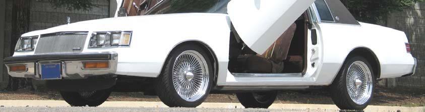
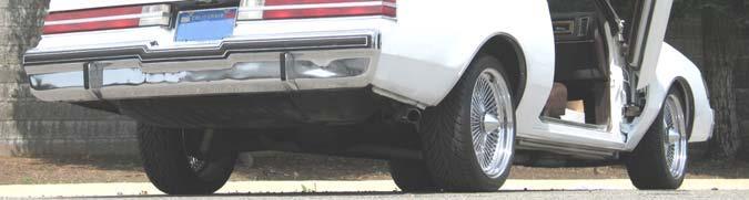
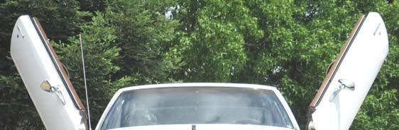
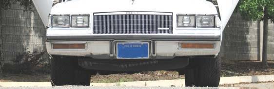
1 GM G-BODY LSD INSTALLATION


2


3 INSTALLATION INTRODUCTION 1. REMOVING THE FENDER AND DOORS FROM THE A-PILLAR AND DISCONNECTING THE WIRE THE DOOR JAM 2. REMOVING THE EXISTING DOOR HINGES FROM THE DOORS; TOP AND BOTTOM. 3. MODIFYING THE INTERNAL FENDER AREAS FOR THE HINGE CLEARANCE. 4. MODIFYING THE ELECTRICAL HARNESS. 5. HANGING AND ALIGNING THE VEHICLE DOORS. 6. INSTALLING THE FENDER AND CHECKING FOR CLEARANCE. 7. REMOVE FENDER AND ROUTING THE WIRING. 8. RE-INSTALL FENDER AND CHECK FOR CLEARANCE. 9. JOB COMPLETE!
4 Installation Instructions LamboStyleDoors (The instructions are to be used as a reference only. Please repeat steps for both doors.) Pre-installation check list: Battery disconnected Front bumper removal Front fender removal Vehicle must be accident free Vehicle must have inner fender cover Disassemble the door stopper Preparations: (Disassemble parts according to the vehicle manufacturers specifications) Disconnect the wire harness between the chassis and the door (remove the harness from the door interior when necessary) Disassemble the door. For this procedure, un-bolt the from the A-Pillar. Un-bolt the hinges located on the door. Extend the factory door wire harness with the enclosed wire harness extension kit. Modify the fender Relocate the door lock vacuum case (when necessary). (e.g. from the passenger s side inner fender to the engine compartment) Modify the windshield washer reservoir (when necessary).
5 Safety Information: LSD door kits must be installed according to the vehicle-specific instructions provided by LSD-Doors. The installation should be performed by an authorized dealer. When extending factory wire harness, follow the vehicle manufacturer's guidelines for cable repairs. When extending CAN-bus, pay attention to the processes of rerouting, screening, and twisting (check vehicle manufacturer's specifications). Be careful not to damage any systems. After installation of the kit, side airbags (if any) should be tested for proper operation by an authorized dealer. Performing final adjustments of the doors, make sure they close and lock according to the OEM specifications (check original closing angles, locking positions, gaps, etc.). Be careful while working in the operating area of the doors and hinge system (be especially careful when working with a partner or when there are other people in the working area). All doors must be securely closed before setting vehicle into motion. Driving with open doors is prohibited. Do not mount heavy loudspeakers without increasing pressure of the gas spring. Adjust horizontal opening angle of the doors to the possible maximum. The gas spring should hold your door at the maximum height under all operating conditions. To guarantee that, choose gas spring with the appropriate pressure level. Empty door storage compartments, otherwise all the objects placed in there will fall as the door opens and the weight of the door will change, which may influence the gas spring operation. WARNING: gas spring is under extreme pressure! Make sure all mounting brackets are securely fastened in the right places. General instructions: A properly instructed partner will make the installation process easier. Regular servicing of the doors and gas springs at a specialized body shop will expand their service life.! Attention! An additional inside handle must be installed to simplify opening and closing of the doors from seated position. White door lights must be disabled via removal of light bulbs or bulb sockets in accordance with Fig of ECE Reg. No. 48. After installation of the LSD hinge system, reinstall original inner fender cover to keep LSD hinges free from debris. Functionality of the vehicle comfort systems, e.g., central locking system (if any), must be checked at an authorized body shop. Check functionality of all other systems and components (loudspeakers, anti-theft systems, CAN-bus, window rollers, crash-sensors, driver seat memory, mirror heating/adjustment, etc.) at an authorized body shop. When adjusting the doors, be careful to place them in the proper door openings not to cause any damage to other components. The processes of adjustment and testing must be performed with great attention. If A-pillar or doors have been modified, use supplied chassis glue (if specified in the list and included in the set) for tight joint. Make sure that sealed surfaces are free from dust and grease before applying chassis glue. Proper door sealing will guarantee safety. Note: gas springs have been tested on standard doors. If your doors come with additional equipment, it may slightly modify their weight and you may need to order stronger or lighter gas spring (additional costs may arise). Please note that the gas spring pressure may vary due to temperature, which will influence opening and closing force. Warranty claims will not be honored unless there is defect in material or workmanship. When body work is performed, apply anti-corrosion covering to all the modified surfaces according to the manufacturer s guidelines. After the LSD kit installation, the doors opening angle is limited. The doors must be first carefully opened outwards and then upwards. When too much force is applied to the limiters/stop points body parts may damage. The warranty does not cover damages caused by improper use, improper installation, or application of excessive force to the limiters/stop points.
6 General Lubrication Information In order for the LSD Door System to function properly, adequate lubrication is essential at all pivot points on the system. Periodic lubricating of all pivot points is highly recommended on a consistent basis. This helps in the life of all bearings involved and provides for a smooth operating LSD Door System. Listed below are helpful hints of when to lubricate: - After washing the vehicle, open the doors and check to see that all pivot points are properly greased - Every three months, open doors and check to see that all pivot points are properly greased - If the vehicle is subject to a harsh environment, such as salt or sand, it is critical that all pivot points stay lubricated, especially if the doors are being used frequently. Open the doors and check to see that all pivot points are greased properly
 1x A 9x")


7 HARDWARE LIST ( per vehicle side) 1x A 9x B 3x C 3x D Snap ring Serrated bolt 30mm Hexagon bolt 50mm C-Profile Shim 3x E 1x F 5x G 1x H 2600 N Cover A-Pillar Glue Tie wraps Damper 3x I 1x J 1x K 1x L Screw LSD Door System LSD Swing Arm LSD Ground Plate 4x M Grommet
8 2 4 B 5 C A 1 B C
. 1b. Un-bolt the four bolts that mount the O.E.M.")

9 STEP 1 REMOVING THE O.E.M. DOOR AND O.E.M. HINGES 1a. Open the door and locate the door hinges (Photo 1). 1b. Un-bolt the four bolts that mount the O.E.M. hinges (with the doors attached) and remove them completely off the A-Pillar. 1c. Remove the four bolts mounting the hinges to the door frame, removing the hinges completely. HINGE TOP MOUNTING BOLTS DOOR A-PILLAR HINGE BOT MOUNTING BOLTS PHOTO 1

10 STEP 2 DIS-ASSEMBLING THE SWING ARM FROM THE GROUND PLATE 2a. Your new LSD Door Hinges have come assembled. 2b. As identified in (Photo 2), disassemble the swing arm from the ground plate. Un-bolt all four mounting bolts or allen-heads and remove completely, detaching the swing arm from the ground plate. 2c. Place the four mounting bolts in an area where they will not be lost. GROUND PLATE SWING ARM PHOTO 2 PHOTO FOR REFERENCE ONLY
 IMPORTANT NOTE: Prior to beginning extending the wiring harness from the A-pillar, each individual wire needs to be cut")

 3b. Isolate a single wire (Photo 3).")
 back approximately 1/4 (Photo 4). Twist the end tight. 3d.")
11 VERY IMPORTANT: DIRECTIONS BELOW ARE APPLICABLE IF THE VEHICLE IS EQUIPPED WITH ELECTRIC WINDOWS AND ELECTRIC DOOR LOCKS STEP 3 MODIFYING THE CHASSIS WIRING HARNESS (IF APPLICABLE) IMPORTANT NOTE: Prior to beginning extending the wiring harness from the A-pillar, each individual wire needs to be cut one at a time. Each wire that is cut, has to be staggered (See 4g) from the previous cut wire. By doing this, you will eliminate, when wrapping all the wires, one large taped ball. 3a. If the wiring harness comes equipped with an insulation cover, this will need to be removed. STEPS 3b thru 3f are for REFERENCE ONLY (using the white wire as reference) 3b. Isolate a single wire (Photo 3). Start the first cut on the white wire approximately 3 from the door frame. 3c. Cut the wire sheath (coming from door frame) back approximately 1/4 (Photo 4). Twist the end tight. 3d. Cut the wire sheath (from kit supplied white wire) back approximately 1/4. Twist the end tight. 3e. Using the kit supplied heat shrink connector ends, insert the wire ends into the connector, one from each end (Photo 5). 3f. Using the heat gun, shrink wrap the connector ends to securely mate with the wire ends (Photo 6). PHOTO 3 PHOTO 4 PHOTO 5 PHOTO 6


12 STEP 4 MODIFYING THE CHASSIS WIRING HARNESS (IF APPLICABLE) cont d- 4g. VERY IMPORTANT: FOLLOW THE DIRECTIONS BELOW IF THE VEHICLE IS EQUIPPED WITH ELECTRIC WINDOWS AND DOOR LOCKS 4h. Remember to stagger the cuts for each individual wire. This will eliminate having a large wrap and will allow for minimal size and maximum flexibility. 4i. In the photo below an (INCORRECT) version is shown. By cutting it this way, wrapping the wire at the end, will create a large ball in the middle of the newly extended wire harness. 4j. By staggering the cuts, (CORRECT), you eliminate creating a large taped ball, thus making it easier to install back in the chassis. 4k. Prior to soldering on the A-Pillar wire connector end, its important to remember to in stall the original equipment rubber grommet (Photo 7) (IF APPLICABLE) 4m. Once the rubber grommet has been fed onto the new extension wire harness, you are able to attach the wire connector end of the A-Pillar (Photo 8). INCORRECT CUTS CORRECT CUTS RUBBER GROMMET LOCATION PHOTO 7 PHOTO 8 IF APPLICABLE


 shows what the final cut")
13 STEP 5 MODIFYING THE FENDER 5a. Mark the areas on the fender that are going to be modified (Photo 11). For detailed dimensions, see Page 15. 5b. Using a pneumatic air saw, cut the areas that you have designated to remove. 5c. (Photo 12) shows what the final cut should look like. BEFORE PHOTO 11 AFTER PHOTO 12
14 STEP 5 MODIFYING THE FENDER cont d- 5d. In (Photo 13), the area has been marked for removal. A minimum lip is required along the face edge indicated, no less than 2mm(.06in.), up to a maximum width of 30mm (1.18in.), as shown below. 5e. In (Photo 14), dimensions are given from the face edge of the fender. FACE EDGE 110mm(4.33 ) 460mm(18.11 ) 280mm(11.00 ) 120mm (4.72 ) PHOTO 13 FACE EDGE 30mm(1.18 ) 10mm(.393 ) 2mm(.06 ) PHOTO 14 5f. In (Photo 14), the shaded area is the area needing to be removed.

.")

 and mark a line (Photo 14B).")
15 STEP 5 MODIFYING THE A-PILLAR FENDER ATTACHMENT LIP cont d- 5g. Mark off the Fender Attachment Lip, located on the A-Pillar (Photo 14A). There are two modifications needing to be done at this location. 5h. Measuring from the top, come down 40mm(1.57 ) and mark a line (Photo 14B). In the bottom photo, the final modification here is shown. 40mm FENDER LIP PHOTO 14B ER LIP PHOTO 14A FINAL MODIFICATION


.")
. 120mm(4.")
16 STEP 5 MODIFYING THE INNER FENDER ATTACHMENT cont d- On this vehicle, the inner fender will need to be notched at the bottom, as the following step shows. 5i. Mark the bottom of the inner fender, as shown (Photo 14C). This notch is clearance for the bottom of the Ground Plate (Photo 14D). 120mm(4.72 ) 100mm (3.93 ) NOTCH PHOTO 14C PHOTO 14D
.")
, insert the bolts and finger tight only. 6c.")
17 STEP 6 MOUNTING THE LSD GROUND PLATE 6a. Using the existing O.E.M. tapped mounting holes, mount the LSD ground plate matching up each respective mount hole. Three mount holes at the top and three at the bot tom (Photo 15). Locate the mounting bolts at the center of their respective slotted mount holes. 6b. Using the kit supplied mounting bolts (L, K), insert the bolts and finger tight only. 6c. Using a wrench, torque the bolts to 20ft-lb. L TOP MOUNT L BOT MOUNT PHOTO 15
. Locate the mounting bolts at the center of their respective slotted mount holes. 7b.")
 (Photo 17) are longer than the two top mount bolts. These are longer, due to the thickness of the two plates.")
18 STEP 7 MOUNTING THE LSD SWING ARM 7a. Using the existing O.E.M. tapped mounting holes, mount the LSD swing arm, matching up each respective mount hole. Two mount holes at the top and three at the bottom (Photo 16). Locate the mounting bolts at the center of their respective slotted mount holes. 7b. Using the kit supplied mounting bolts (L), insert the bolts and finger tight only. IMPORTANT NOTE: The three bottom mount bolts(50mm) (Photo 17) are longer than the two top mount bolts. These are longer, due to the thickness of the two plates. 7c. Using a wrench, torque the bolts to 20ft-lb. TOP MOUNT BOLTS PHOTO 17 BOTTOM MOUNT BOLTS PHOTO 16
 Initially, this is done for mounting purposes only, using the MAGICSTIK as a guide.")
19 STEP 8 MOUNTING THE DOOR TO THE A-FRAME IMPORTANT NOTE: THIS STEP SHOULD BE DONE WITHOUT THE GAS SPRING IN STALLED 8a. Place the door back on the vehicle and close the door completely. 8a. Install the MAGICSTIK into position (Photo 18) Initially, this is done for mounting purposes only, using the MAGICSTIK as a guide. 8b. Lifting the door into position, guide the MAGICSTIK into its mating block (Photo 19), manually holding the door there, as close to the closed position as possible. 8c. Attach the swing arm to the ground plate with the four (4) kit supplied bolts and adjust the door via moving the swing arm adjustable plate connection mount with the horizontal door gap adjuster in the right or left direction until the gap measurement is like the original (Photo 20). PHOTO 18 PHOTO 20 IMPORTANT NOTE: Torque mounting bolt to 10ft-lb. PHOTO 19 ADJUSTING THE DOOR HEIGHT 8d. Adjustment height of the door is by moving the chassis plate (Q) vertically. Make sure the mounting hardware (L,K) is loosened to perform this function. 8e. Adjustment depth of the door is by moving the door horizontal. Make sure the mounting hardware (L) is loosened to perform this function.
 as a point to guide the front door into the correct position. 8g.")

. 8h.")

20 STEP 8 ADJUSTING THE DOOR HEIGHT cont d 8f. Use the adjustment screw (Photo 21) as a point to guide the front door into the correct position. 8g. Attach the Swing Arm to the chassis plate with the (Photo 22) four(4) kit supplied bolts or allen-head bolts, and adjust the door by moving the Swing Arm to the chassis plate adjustable connection mount with the horizontal door gap adjuster (2) in the left or right direction until the gap dimension is the same O.E.M dimension (prior to disassembling the door). 8h. Adjust the height of the door by moving the chassis plate vertically (up or down) (Photo 23). Loosen the mount bolts prior to adjusting, but not removing them completely. The use of a rubber mallet would be useful in moving the chassis plate. GROUND PLATE MOUNT BOLT SWING ARM MOUNT BOLT PHOTO 21 SWING ARM MOUNT BOLT GROUND PLATE MOUNT BOLT PHOTO 22 PHOTO 23
 (lower")


21 STEP 8 IF REQUIRED 8k. If the Magic Stick (Photo 24) (lower adjustment screw)(1) is not in the correct position when the door is closed, a spacer (Photo 25) (D) has to be installed under the M.A.R.A (2) as shown in the pictures below. PHOTO 24 D 2 D 2 STEP 1A - TOP STEP 2A - BOTTOM D 2 D 2 STEP 1B - TOP STEP 2B - BOTTOM PHOTO 25


22 STEP 8 ADJUSTING THE DOOR OPENING cont d The door openings of vehicles will vary from one model to another. This adjustment controls the gap between the edge of the door and the edge of the fender. This opening-dimension has been pre-determined by our R&D Techs. 8m. With the fender removed, slowly open the door. Using a measuring tape, measure from the outside top corner of the door to the frame of the chassis (Photo AA). IMPORTANT NOTE: IT IS VERY IMPORTANT TO INSTALL ONTO THE ADJUSTMENT SCREW, LOC-TITE. THIS WILL PREVENT THE ADJUSTMENT SCREW FROM BECOMING LOOSE OVER A PERIOD OT TIME. 8n. Once this width of opening has been established, tighten the ADJUSTMENT SCREW on the M.A.R.A. system (Photo BB). 780mm(30 ) PHOTO - AA
, you can now slowly lift the door to the upward position, checking for any interference. 8p.")
 AD")
23 STEP 8 ADJUSTING THE DOOR OPENING cont d 8n. Once this width of opening has been established, tighten the ADJUSTMENT SCREW on the M.A.R.A. system (Photo BB). 8o. Once you have tighten the ADJUSTMENT SCREW (with Loctite ), you can now slowly lift the door to the upward position, checking for any interference. 8p. Locate the door back to the closed position. 8q. Re-install the fender back on the vehicle. Open the door slowly and place it in the upward position, checking for any interference with the fender as it is being lifted upward (Photo CC) ADJUSTMENT SCREW M.A.R.A. SYSTEM PHOTO - BB PHOTO CC If interference occurs with fender-to-door, Steps 8m and Step n will need to be repeated, until the door is fine-tuned into position.
24 STEP 9 MOUNTING THE GAS DAMPER (after correct gap distance has been established) IMPORTANT NOTE: PRIOR TO MOUNTING THE GAS DAMPER AT ITS RESPECTIVE MOUNTING POINTS, WE HIGHLY RECOMMEND USING AN ANTI-RUST LUBRICANT, WIPING DOWN THE MOUNT POINTS TO PRE- VENT RUSTING. KEEPING THE MOUNTING POINTS LUBRICATED, ENHANCES THE LONGEVITY OF THE LSD DOOR SYSTEM IN WORKING PROPERLY GAS DAMPER TOP PIVOT POINT ON LSD SWING ARM GAS DAMPER BOTTOM PIVOT POINT ON LSD GROUND PLATE
 the gas damper (H) on the mount point of the Swing Arm (Photo 26). Secure it with the kit supplied security ring, by using needle-nose pliers. 9b.")
.")
25 STEP 9 MOUNTING THE GAS DAMPER (after correct gap distance has been established) 9a. Hang (mount) the gas damper (H) on the mount point of the Swing Arm (Photo 26). Secure it with the kit supplied security ring, by using needle-nose pliers. 9b. NOTE: Use care when installing the security ring. 9c. Carefully pivot the door up and hang in the gas damper at the fitting point of the chassis plate (Ground Plate). Secure it with the kit supplied security ring (Photo 27). PHOTO 26 PHOTO 27 DANGER: The gas damper is under extreme pressure! Please make sure the security rings are installed correctly and are snapped in their respective guides.

. 10b.")
. 10c.")

26 STEP 10 ROLLER ADJUSTMENT IMPORTANT NOTE: The door needs to be in the closed position for this adjustment to be properly done. NOTE: This adjustment also needs to be done with the gas damper installed. 10a. Install the kit supplied slide roller (as shown in the picture). 10b. Adjust the slide roller (4) so the LSD swing arm has the initial contact and preload while opening and closing of the door. (Photo 28). 10c. Periodically lubricate the slide roller to insure a constant smooth open/close sequence. HORIZONTAL ADJUSTMENT 4 4 VERTICAL ADJUSTMENT T O P V I E W SWING ARM PLATE PHOTO 28

27 STEP 11 ROUTING THE WIRE HARNESS 11a. Pivot the door carefully up and make sure there is sufficient clearance on the fender, A- pillar and hood. If there isn t enough slack on the wiring harness, two things can happen. One, you can damage the wiring harness itself, separating all the connectors. Or two, the door will have trouble opening to its full opening position. If necessary, adjust the LSD chassis plate or the LSD swing arm again. 11b. Lay the wire harness on and attach it to the marked points shown (Photo 29). Secure the wire harness with the kit supplied cable ties. The wire harness is located on the backside of the LSD chassis plate. PHOTO 29
28 COMMON TROUBLESHOOTING QUESTIONS and ANSWERS Q1: WHY DOES THE BOTTOM OF THE DOOR NOT SIT FLUSH, AT THE FRONT OR REAR?: A1: LSD door hinges are engineered and designed to compensate for this issue. They are designed to be installed in the center location of all mounting slots. Some vehicles are different however; adjusting the location of the swing arm mounts on the door will fix this problem. Mounting the swing arm towards the interior of the door, top or bottom will move the door out; mounting the swing arm towards the exterior of the door will move the door in. In some cases, the mounting will be slightly different between top and bottom mounts. Q2: WHY DO THE DOORS SPRING A-JAR WHEN OPENING THE DOOR?: A2: LSD door hinges are engineered and designed to compensate for this issue. It is common on vehicles that the left and the right sides are not quite the same. When a door springs open there is a misalignment between the swing arm and the ground plate. This can be remedied by increasing the distance of the third point on the ground plate. The third point is usually located towards the front of the vehicle. Increasing the distance and angle of the ground plate to the vehicle will release any pressure and/or contact between the swing arm and the ground plate. Q3: WHY DOES THE DOOR HITS/RUBS AGAINST THE FENDER WHEN OPENING?: A3: LSD door hinges are engineered and designed to compensate for this issue. Attaching the LSD hinge in the center location of the slots and adjusting the magic stick such that the tuff lock is centered is the optimum desired installation. Making minor adjustments to the MARA / C profile, the third point, and/or the Magic stick should alleviate this problem. Q4: WHY IS THE WIRING HARNESS TOO LARGE FOR THE ROUTE SHOWN IN THE INSTRUC- TIONS?: A4: LSD door hinges are engineered and designed to compensate for this issue. LSD wiring kits are designed for the MAXIMUM wires installed on vehicles. If additional wires are added or modified that are larger than original, wiring routing might have to be modified. Vehicle owners are responsible for this modified routing. Q5: WHY DOESN T THE GAS SPRING HOLD THE DOOR UP?: A5: LSD door hinges are engineered and designed to compensate for original door weight, i.e. speakers and electronics. NOTE: As temperature fluctuates, the gas pressure in each shock increases or decreases. Example; in the heat, the gas pressure will expand, in the cold; it has a tendency to contract. Any modifications to the speakers or electronics may require a larger gas spring. Vehicle owners are required to purchase these larger gas springs from their local dealer. If you have not modified your door, your gas spring may be faulty. Vehicle owners are required to contact their local dealer for replacement(s).
29

30
CHEVROLET TAHOE/DENALI/AVALANCHE/YUKON/ SILVERADO/SIERRA 2007+
 CHEVROLET TAHOE/DENALI/AVALANCHE/YUKON/ SILVERADO/SIERRA 2007+ INSTALLATION INTRODUCTION 1. REMOVING THE FENDER AND DOORS FROM THE A-PILLAR AND DISCONNECTING THE WIRE HARNESS @ THE DOOR JAM 2. REMOVING
TOYOTA SCION XB 2005 LSD INSTALLATION
 TOYOTA SCION XB 2005 LSD INSTALLATION 50056005 TOYOTA SCION XB 07/07 1 Date 07/24/2007 50056005 TOYOTA SCION XB 07/07 2 INSTALLATION INTRODUCTION 1. REMOVING THE FENDER AND DOORS FROM THE A-PILLAR AND
Installation Instructions LamboStyleDoors (The instruction are to be used as a reference. Please repeat for both doors)
") Installation Instructions LamboStyleDoors (The instruction are to be used as a reference. Please repeat for both doors) Mercedes C-Class Sport coupé type W203 Part number 500 25 009 Pre installation check
Installation Instructions LamboStyleDoors (The instruction are to be used as a reference. Please repeat for both doors) Mercedes C-Class Sport coupé type W203 Part number 500 25 009 Pre installation check
Installation Instructions LamboStyleDoors (The instruction are to be used as a reference. Please repeat for both doors)
") Installation Instructions LamboStyleDoors (The instruction are to be used as a reference. Please repeat for both doors) Pre installation check list: - Double check vehicles data with TUV certificate -
Installation Instructions LamboStyleDoors (The instruction are to be used as a reference. Please repeat for both doors) Pre installation check list: - Double check vehicles data with TUV certificate -
Installation Instructions LamboStyleDoors
 Installation Instructions LamboStyleDoors (The instruction refers only to one side of the car, but is valid for both sides) Preparations: (Dismantling according to the regulation of the car manufacturer)
Installation Instructions LamboStyleDoors
 Installation Instructions LamboStyleDoors (The instruction refers only to one side of the car, but is valid for both sides) Preparations: (Dismantling according to the regulation of the car manufacturer)
Installation Instructions LamboStyleDoors
 Installation Instructions LamboStyleDoors (The instruction refers only to one side of the car, but is valid for both sides) Preparations: (Dismantling according to the regulation of the car manufacturer)
Installation Instructions LamboStyleDoors (The instruction are to be used as a reference. Please repeat for both doors)
") Installation Instructions LamboStyleDoors (The instruction are to be used as a reference. Please repeat for both doors) Hyundai enesis Coupé type BK38 Part number 500 66 002 Pre installation check list:
Installation Instructions LamboStyleDoors (The instruction are to be used as a reference. Please repeat for both doors) Hyundai enesis Coupé type BK38 Part number 500 66 002 Pre installation check list:
Installation Instructions LamboStyleDoors (The instruction are to be used as a reference. Please repeat for both doors)
") Installation Instructions LamboStyleDoors (The instruction are to be used as a reference. Please repeat for both doors) Ford Mustang type LAE Part number 500 80 30 016 Pre installation check list: - Vehicle
Installation Instructions LamboStyleDoors (The instruction are to be used as a reference. Please repeat for both doors) Ford Mustang type LAE Part number 500 80 30 016 Pre installation check list: - Vehicle
Made in USA with U.S. PATENT #6,808,223; #6,845,547; #7,140,075; #7,059,655 and other patents pending.
 Made in USA with U.S. PATENT #6,808,223; #6,845,547; #7,140,075; #7,059,655 and other patents pending. Page 1 of 12 CHEVROLET CAMARO 1993-2002 Vertical Doors Canada, Inc / Lambo Doors Canada, Inc. 1 888
RHINO SUSPENSION SYSTEM INSTALLATION INSTRUCTIONS
 PARTS INCLUDED: 2 FRONT UPPER A-ARMS 2 FRONT LOWER A-ARMS 2 UNI-BALL JOINTS 2 UNI-BALL JOINT STUDS 2 UNI-BALL JOINT CAPS 2 RETAINING RINGS 1 FRONT SHOCK ASSEM. 2 DELRON STEERING STOPS 2 SHOCK MOUNT SPACERS
Part Number: TTU-BGB14-DRL TTU-BGP14-DRL
 11/15/16 TOYOTA TUNDRA 2014-17 Billet Grille w/led DRL Part Number: TTU-BGB14-DRL TTU-BGP14-DRL Kit Contents Item # Quantity Reqd. Description 1 2 LED DRL 2 1 Driver Box 3 1 Switch 4 1 User Card 5 2 Hardware
I N S T A L L A T I O N G U I D E
 I N S T A L L A T I O N G U I D E APPLICATION AMP Part # Chevrolet Silverado1500 / GMC Sierra 1500 - Crew Cab 2014-2015 77154-01A Chevrolet Silverado 2500/3500 - Crew Cab 2015 77154-01A (Gas Only) GMC
LPE C5 Battery Relocation Kit
 LPE C5 Battery Relocation Kit The LPE C5 Corvette battery relocation kit improves vehicle weight distribution by moving weight to the rear of the vehicle. The improved weight distribution increases traction
Stowe Cargo Management System
 Installation Guide Stowe Cargo Management System Table of Contents 1. Pre-Installation (Page 2) a. Notes, Installation Kit contents & Tools needed 2. How to Install the Stowe Cargo Management System (Pages
TOYOTA 4RUNNER COLD AIR INTAKE FJ CRUISER Preparation
 Preparation Part Number: PTR03-89100 Kit Contents Item # Quantity Reqd. Description 1 1 Air Filter (P/N: PTR43-00083) 2 1 Upper Air Box 3 1 Lower Air Box 4 1 Hump Coupler 5 1 Throttle Body Coupler 6 1
INSTALLATION & OWNER S MANUAL
 Rev. B, p. 1 of 25 INSTALLATION & OWNER S MANUAL POLARIS RANGER RCS (for models XP or HD) (for model years 2009-) cab without doors kit (p/n 1POLRCWD) cab with doors kit (p/n 1POLRC) doors only kit (p/n
EVO-1162 EVO Tailgate Tire Carrier
 EVO-1162 EVO Tailgate Tire Carrier Bill of Materials EVO-1162 Tailgate Tire Carrier Part number Description Quantity EVO-12161 EVO Tailgate Tire Carrier 1 EVO-12162 Bolt Plate 1 EVO-12163 Wheel Mount 1
Installation Notes: #86000-R Race Series +3.5 L/T Kit
 159 North Maple St. Unit J, CORONA CA 92880 P. 951-737-9682 F. 951-737-9006 WWW.CHAOSFAB.COM Installation Notes: #86000-R Race Series +3.5 L/T Kit Factory manual is recommended for removal and re-installation
Ram 1500 Crew Cab A Ram 2500/3500 Crew Cab A
 I N S T A L L A T I O N G U I D E APPLICATION AMP Part # Ram 1500 Crew Cab 2013-2015 77138-01A Ram 2500/3500 Crew Cab 2013-2015 77138-01A Note:The application works only on the Crew Cab model Vehicles.
*Enclosed pictures and devices are for reference only. Individual vehicles and devices may vary.
 Dash Strap Mount Product Number AS5.S500.001 *Enclosed pictures and devices are for reference only. Individual vehicles and devices may vary. The Dash Strap Mount is held tight against the vehicle dash
Installation Manual TWM Performance Short Shifter Cobalt SS/SC, SS/TC, HHR SS, Ion Redline and Saab 9-3
 Page 1 Installation Manual TWM Performance Short Shifter Cobalt SS/SC, SS/TC, HHR SS, Ion Redline and Saab 9-3 Please Note: It is preferable to park on a flat surface, as you will have to engage and disengage
Installation Instructions
 Preparing your vehicle to install your brake system upgrade 1. Rack the vehicle. 2. If you don t have a rack, then you must take extra safety precautions. 3. Choose a firmly packed and level ground to
Installation Manual TWM Performance 2010 Mazda 3 short shifter 5 and 6 speed non-mazdaspeed
 Installation Manual TWM Performance 2010 Mazda 3 short shifter 5 and 6 speed non-mazdaspeed Begin the installation by parking on a flat surface, as you will have to engage and disengage the hand brake
Ford Mustang GT-Style Fog Light Kit Parts List: Quantity: Tool List:
 2013-2014 Ford Mustang GT-Style Fog Light Kit Parts List: Quantity: Tool List: Fog light (Left& Right) 2 Flat head & Phillips screwdriver Upper grille with surround 1 Ratchet & Socket set OR Lower grille
Assembly Manual. 1/10th Formula 1 Car
 Assembly Manual 1/10th Formula 1 Car Center Pivot Bag 1 3374 - Center Pivot Socket 40194 - Hard Anodized Alum Pivot ball 3254-2-56 *Note - Sometimes it is helpful to slightly over-tighten the top clamp
INSTALLATION INSTRUCTIONS FOR THE MOTOR TRIKE GL1500 RAKE KIT
 INSTALLATION INSTRUCTIONS FOR THE MOTOR TRIKE GL1500 RAKE KIT Thank you for choosing the Motor Trike GL1500 Rake Kit. We ask that you read the directions before you start and follow them very closely.
GENUINE PARTS INSTALLATION INSTRUCTIONS
 GENUINE PARTS INSTALLATION INSTRUCTIONS DESCRIPTION: APPLICATION: PART NUMBER: Electronic Tailgate Lock Kit Nissan Titan 999M2-W3005 KIT CONTENTS: Item Qty. Part Description Service Part Number A 1 Electronic
Remove the 3-11mm nuts holding mirror on. Don t drop the nuts!
 2005-2012 Ford Mustang Puddle Lamp Kit Parts List: Quantity: Tool List: LED Lamps 2 Flat head screwdriver Seals 2 Ratchet & Socket set OR Nuts 2 Adjustable Wrench Wiring harness 1 Drill & 11/16 th bit
Remove 4 circled pins. Route wiring along dashed line. Remove the 2 9mm nuts and black retaining plate that secure extractor.
 2015 Ford Mustang Turn Signal Hood Kit Parts List: Quantity: Tool List: Bracket & pre-installed lamp 2 Flat head screwdriver Wiring harness 1 Phillips screwdriver PB-3660 Parts Bag 1 Ratchet & Socket set
'99-03 CHEVROLET/GMC IFS 4WD 6" SUSPENSION SYSTEM P/N INSTALLATION INSTRUCTIONS
 1/16/04 '99-03 CHEVROLET/GMC IFS 4WD 6" SUSPENSION SYSTEM P/N. 10-41099 INSTALLATION INSTRUCTIONS NOTE: Each Lift Kit and options to Lift Kits are packaged separately. Therefore, installation procedures
2015 Mustang Lightbar (All Models) CDC#
 CDC#") 2015 Mustang Lightbar (All Models) CDC# 1511-7000-01 Components: 1 CDC Lightbar Note: READ instructions before starting installation!!! CDC Part# Driver side bracket 0511-6001-05 Passenger side bracket
2015 Mustang Lightbar (All Models) CDC# 1511-7000-01 Components: 1 CDC Lightbar Note: READ instructions before starting installation!!! CDC Part# Driver side bracket 0511-6001-05 Passenger side bracket
INSTALLATION OF THE ENCLOSURE FOR THE MULE 3010 TRANS INSTALLATION GUIDE FOR THE MULE 3000 TRANS ENCLOSURE P. 1. Sept 07
 INSTALLATION GUIDE FOR THE MULE 3000 TRANS ENCLOSURE P. 1 INSTALLATION OF THE ENCLOSURE FOR THE MULE 3010 TRANS Sept 07 www.essexmfg.com PO Box 92864 Southlake, TX 76092 Ph:888-643-7739 INSTALLATION GUIDE
TOYOTA TUNDRA BIG BRAKE KIT Section I - Installation Preparation
 TOYOTA TUNDRA 2007- BIG BRAKE KIT Section I - Installation Preparation Part Number: PTR09-34070 Kit Contents Item # Quantity Reqd. Description 1 1 Brake Rotor, LH Front 2 1 Brake Rotor, RH Front 3 1 Brake
3-5 Hours Professional installation recommended
 I N S T A L L A T I O N G U I D E APPLICATION MODEL YR PART # Toyota Tacoma Double Cab 2016 75162-01A Toyota Tacoma Access Cab* 2016 75162-01A * Modification required to running board assembly. See Item
Subaru Front Mount Intercooler Kit STI Subaru Front Mount Intercooler Kit STI
 Subaru Front Mount Intercooler Kit STI 2008-2014 715500 Subaru Front Mount Intercooler Kit STI 2008-2014 Congratulations on your purchase of the Subaru Front Mount Intercooler Kit STI 2008-2014. The following
SCION tc STRUT TIE BAR Preparation
 SCION tc 2005 - STRUT TIE BAR Preparation Part Number: 00016-80440 Code: YY1 Kit Contents 1 1 DS Mount Plate 2 1 PS Mount Plate 3 1 Cross Bar 4 1 Hardware Bag Hardware Bag Contents 1 4 8mm Screws 2 4 8mm
AMP RESEARCH TECH SUPPORT (Press 2) Monday - Friday, 6:00 AM - 5:00 PM PST
 Monday - Friday, 6:00 AM - 5:00 PM PST") APPLICATION AMP Part # Jeep Wrangler Unlimited (JK) 2007 2017 78122-01A (-Door Only) INSTALLATION TIME 3-5 Hours Professional installation recommended SKILL LEVEL 1 2 3 = Experienced TOOLS REQUIRED q 13
APPLICATION AMP Part # Jeep Wrangler Unlimited (JK) 2007 2017 78122-01A (-Door Only) INSTALLATION TIME 3-5 Hours Professional installation recommended SKILL LEVEL 1 2 3 = Experienced TOOLS REQUIRED q 13
LoD Offroad. Jeep JK Door Linked Rear Bumper with Tire Carrier Installation Instructions
 LoD Offroad Jeep JK Door Linked Rear Bumper with Tire Carrier Installation Instructions Please read through the instructions before beginning any part of the installation process. Packaging List: 1-Rear
I N S T A L L A T I O N G U I D E
 I N S T A L L A T I O N G U I D E APPLICATION AMP Part # Jeep Wrangler Unlimited (JK) 2007 2017 78122-01A (4-Door Only) INSTALLATION TIME 3-5 Hours Professional installation recommended SKILL LEVEL 1 2
I N S TA L L AT I O N
 I N S TA L L AT I O N 5008 fits: H-D: '80-Up Electra glide, tour glide, road king, road glide or street glide PartS Included 1 Right Fork Mount Assembly 1 Left Fork Mount Assembly 2 H3 Driving Light Assemblies
Maintenance Information
 Form 16575334 Edition 1 April 2005 Electric Screwdrivers EL, EP and ET 34V DC Series Maintenance Information Save These Instructions WARNING Maintenance procedures have the potential for severe shock hazard
Slave Cylinder Weep Hole Drilling Procedure
 Slave Cylinder Weep Hole Drilling Procedure Tools Required: T20 Torx Driver T25 Torx Driver T25 Torx Bit with ¼ Ratchet Wrench 4mm Hex Key (Allen wrench) 5mm Hex Key 6mm Hex Key 8mm Hex Key 12mm Hex Key
INSTALLATION GUIDE. AMP RESEARCH TECH SUPPORT (Press 2) Monday - Friday, 6:00 AM - 5:00 PM PST
 Monday - Friday, 6:00 AM - 5:00 PM PST") INSTALLATION GUIDE APPLICATION AMP Part # Jeep Wrangler Unlimited (JK) 2007 up 75121-01A 2-Door INSTALLATION TIME 3-5 Hours Professional installation recommended SKILL LEVEL 1 2 3 = Experienced TOOLS REQUIRED
INSTALLATION GUIDE APPLICATION AMP Part # Jeep Wrangler Unlimited (JK) 2007 up 75121-01A 2-Door INSTALLATION TIME 3-5 Hours Professional installation recommended SKILL LEVEL 1 2 3 = Experienced TOOLS REQUIRED
OIL COOLER KIT INSTALLATION INSTRUCTIONS PART NUMBER D
 OIL COOLER KIT INSTALLATION INSTRUCTIONS PART NUMBER D570-0904 APPLICATION: 2011-2012 E90 335i/xi (N55 engine) with BMW standard bumper and with stock oil cooler Congratulations for being selective enough
Tusk Pannier Racks. Instructions and information KLR
 1 Tusk Pannier Racks Instructions and information KLR650 2008 + Congratulations on your purchase of the Tusk Pannier Racks. These racks are made to handle extreme adventure riding, but work great for the
3-5 Hours Professional installation recommended
 I N S T A L L A T I O N G U I D E APPLICATION LENGTH MODEL YR PART # Chevrolet Colorado / GMC Canyon - Crew Cab 72 2015-2016 76153-01A Chevrolet Colorado / GMC Canyon - Extended Cab 65 2015-2016 76153-01A
INSTALLATION GUIDE. AMP RESEARCH TECH SUPPORT (Press 2) Monday - Friday, 6:00 AM - 5:00 PM PST
 Monday - Friday, 6:00 AM - 5:00 PM PST") INSTALLATION GUIDE APPLICATION AMP Part # Jeep Wrangler Unlimited (JK) 2007 2015 75122-01A (-Door Only) INSTALLATION TIME 3-5 Hours Professional installation recommended SKILL LEVEL 1 2 3 = Experienced
INSTALLATION GUIDE APPLICATION AMP Part # Jeep Wrangler Unlimited (JK) 2007 2015 75122-01A (-Door Only) INSTALLATION TIME 3-5 Hours Professional installation recommended SKILL LEVEL 1 2 3 = Experienced
FRONT & 4 REAR GM WD LOWERING KIT
 92725200 88-98 2 FRONT & 4 REAR GM 1500 2WD LOWERING KIT Thank you for choosing Rough Country for all your suspension needs. Rough Country recommends a certified technician install this system. In addition
Installation Guide CLAAS Lexion Combines with 9 inch Elevators
 Installation Guide CLAAS Lexion Combines with 9 inch Elevators 955614_01 4/17 1 Table of Contents System Overview 3 Quick Start Guide 4 Flow Sensor Installation 5 Hydraulic Elevator Adjustment Kit Installation
I N S T A L L A T I O N G U I D E. AMP RESEARCH TECH SUPPORT (Press 2) Monday - Friday, 6:00 AM - 5:00 PM PST
 Monday - Friday, 6:00 AM - 5:00 PM PST") I N S T A L L A T I O N G U I D E APPLICATION AMP Part # Jeep Wrangler Unlimited (JK) 2007 2017 78121-01A 2-Door INSTALLATION TIME 3-5 Hours Professional installation recommended SKILL LEVEL 1 2 3 4 4=
I N S T A L L A T I O N G U I D E APPLICATION AMP Part # Jeep Wrangler Unlimited (JK) 2007 2017 78121-01A 2-Door INSTALLATION TIME 3-5 Hours Professional installation recommended SKILL LEVEL 1 2 3 4 4=
LoD Offroad. Jeep JK Rear Bumper with Tire Carrier Installation Instructions
 LoD Offroad Jeep JK Rear Bumper with Tire Carrier Installation Instructions Please read through the instructions before beginning any part of the installation process. Packaging List: 1-Rear Bumper 1-Tire
Installation instructions for Camaro/Firebird and Nova* Windshield Wiper Systems
 Installation instructions for 1967-69 Camaro/Firebird and 1968-74 Nova* Windshield Wiper Systems The Raingear 1967-69 Camaro/Firebird and 1964-74 Nova wiper system is designed for ease of installation
Depress each tab as you pull the bezel off. The bezels are tight. L.H. shown.
 2013-2014 Ford Mustang V6 & Boss 302 Lower Valance Fog Light Kit Parts List: Quantity: Tool List: Fog light & bulb with bracket 2 Flat head & Phillips screwdriver Black bezels 2 Ratchet & Socket set OR
BX7460P Allure Tow Bar Operator Manual & Installation Instructions. ALLURE Tow Bar (10,000 lb) Pintle Coupler
 Pintle Coupler") Operator Manual & Installation Instructions ALLURE Tow Bar (10,000 lb) Pintle Coupler Hooking Up to Towed Vehicle 1. Position the towing vehicle on a level surface with a straight driveway ahead and engage
Operator Manual & Installation Instructions ALLURE Tow Bar (10,000 lb) Pintle Coupler Hooking Up to Towed Vehicle 1. Position the towing vehicle on a level surface with a straight driveway ahead and engage
TOYOTA PRIUS PLUS LOWERING SPRINGS Preparation
 Preparation Part Number: PTR07-47100 Kit Contents Item # Quantity Reqd. Description 1 2 Front Spring 2 2 Rear Spring 3 2 Nut 4 1 Instructions Hardware Bag Contents Item # Quantity Reqd. Description 1 2
NOTICE TO DEALER AND VEHICLE OWNER
 921751200 *1751BAG1* 1751BAG1 Thank you for choosing Rough Country for all your suspension needs. This kit will fit both 4WD and 2WD models, all brackets will be used for 4WD models. On 2WD models the
Installation Instructions Z-Gate Shifter
 Installation Instructions Z-Gate Shifter Part Number 80681 1998, 2001 by B&M Racing and Performance Products The B&M Z-Gate shifter can be used in vehicles equipped with most popular three speed automatic
TOYOTA FJ CRUISER / 4RUNNER COLD AIR INTAKE Section I Installation Preparation. 4.0L V6 (1GR) Roller Rocker Part Number(s): PTR
 Roller Rocker Part Number(s): PTR") Section I Installation Preparation Part Number(s): PTR03-89100 Kit Contents Item # Quantity Reqd. Description 1 1 Air Filter (P/N: PTR43-00083) 2 1 Upper Air Box 3 1 Lower Air Box 4 1 Hump Coupler 5 1
Section I Installation Preparation Part Number(s): PTR03-89100 Kit Contents Item # Quantity Reqd. Description 1 1 Air Filter (P/N: PTR43-00083) 2 1 Upper Air Box 3 1 Lower Air Box 4 1 Hump Coupler 5 1
INSTALLATION & OWNER S MANUAL
 p. 1 of 15 INSTALLATION & OWNER S MANUAL Polaris Ranger 500-800 PathPro SS Cab (fits 2010 - current) (p/n: 1POLRFS1) The contents of this envelope are the property of the owner. Be sure to leave with the
AEV30308AA Last Updated: 05/31/18. 4 DUALSPORT sc SUSPENSION system for RAM 1500 air ride standard and rebel INSTALLATION GUIDE
 AEV30308AA Last Updated: 05/31/18 4 DUALSPORT sc SUSPENSION system for RAM 1500 air ride standard and rebel INSTALLATION GUIDE PLEASE READ BEFORE YOU START TO GUARANTEE A QUALITY INSTALLATION, WE RECOMMEND
LIFTING MECHANISM PART NO SRM 965
 LIFTING MECHANISM B60Z [A230]; B80Z [A233]; C60Z [A478]; C80Z [A479]; W60Z [A231]; W65Z [A229]; W80Z [A234]; B60Z AC [B230]; B80Z AC [B233]; C60Z AC [B478]; C80Z AC [B479] PART NO. 1500202 4000 SRM 965
Tools Needed: Class 8.8 Class MM 55ft/lbs 75ft/lbs 14MM 85ft/lbs 120ft/lbs 16MM 130ft/lbs 165ft/lbs 18MM 170ft/lbs 240ft/lbs
 921788000 JEEP JK 6 LONGARM Rough Country recommends a certified technician install this system. In addition to these instructions, professional knowledge of disassemble/reassembly procedures as well as
Assembly Instructions
 Assembly Instructions Part Number Description Model Approx. Assembly Time 99994-049 Cab Enclosure MULE SX 3-4 Hours WARNING Improper installation of this accessory could result in an accident causing serious
3-5 Hours Professional installation recommended
 I N S T A L L A T I O N G U I D E APPLICATION MODEL YR PART # Toyota Tacoma Double Cab 2005 - up 75142-01A Toyota Tacoma Access Cab* 2005 - up 75142-01A * Modification required to running board assembly.
BX4330 Acclaim Tow Bar Operator Manual & Installation Instructions
 Operator Manual & Installation Instructions (5,000 lb) 2 Inch Coupler General Information DO NOT INSTALL, OPERATE OR USE THIS EQUIPMENT UNTIL THE FOLLOWING OPERATING AND SAFETY INSTRUCTIONS HAVE BEEN READ
SwayPro. NOTE: A minimum tongue weight of 200 lbs. is required THANK YOU
 SwayPro Owner s Manual & Installation Instructions Serial Number Standard Hitch Head w/ Clamp-On Rotating Latches BXW0350 350 lbs. maximum tongue weight capacity BXW0550 550 lbs. maximum tongue weight
Jeep Wrangler (TJ)
") INSTALLATION GUIDE APPLICATION MODEL YR PART # Bestop PART # Jeep Wrangler (TJ) 2003 2006 10-03315-10 751-01 INSTALLATION TIME 3:00 hrs SKILL LEVEL 1 2 3 4 4= Experienced TOOLS REQUIRED Safety goggles
INSTALLATION GUIDE APPLICATION MODEL YR PART # Bestop PART # Jeep Wrangler (TJ) 2003 2006 10-03315-10 751-01 INSTALLATION TIME 3:00 hrs SKILL LEVEL 1 2 3 4 4= Experienced TOOLS REQUIRED Safety goggles
Installation Instructions Pro Bandit Shifter Fits: GM Powerglide Automatic Transmissions
 Installation Instructions Pro Bandit Shifter Fits: 1962-1973 GM Powerglide Automatic Transmissions Part # 80793 WORK SAFELY! For maximum safety, perform this installation on a clean, level surface and
07-UP AVALANCHE 7.5 KIT
 92120900R1 07-UP AVALANCHE 7.5 KIT Thank you for choosing Rough Country for your suspension needs. We appreciate your business!! This kit will not fit vehicles equipped with electric steering or trucks
5.5 Gas & 6 Diesel Radius Arm Suspension System. Dodge Ram WD Pickup Dodge Ram WD Pickup
 Part#: 012610 5.5 Gas & 6 Diesel Radius Arm Suspension System Dodge Ram 3500 4WD Pickup 2013-17 Dodge Ram 2500 4WD Pickup 2014-17 491 W. Garfield Ave., Coldwater, MI 49036. Phone: 517-279-2135 Web: www.bds-suspension.com.
»Product» Safety Warning
 F2650 Installation Instructions 2017-18 Ford F150 4WD 4-6" Suspension Systems Read and understand all instructions and warnings prior to installation of product and operation of vehicle. Zone Offroad Products
Installation Manual TWM Performance Short Shifter Subaru STi 2008+
 - 1 - Installation Manual TWM Performance Short Shifter Subaru STi 2008+ Please Note: It is preferable to park on a flat surface, as you will have to engage and disengage the hand brake and shift from
SW38PRE - 38 Tow Behind Lawn Sweeper
 SW38PRE - 38 Tow Behind Lawn Sweeper Owner s Manual and Parts List Precision Products, Inc. Customer Service & Warranty Information PLEASE DO NOT RETURN THIS MERCHANDISE TO THE STORE. CALL US AND WE WILL
I N S T A L L A T I O N G U I D E. AMP RESEARCH TECH SUPPORT (Press 2) Monday - Friday, 6:00 AM - 5:00 PM PST
 Monday - Friday, 6:00 AM - 5:00 PM PST") I N S T A L L A T I O N G U I D E APPLICATION AMP Part # Jeep Wrangler Unlimited (JK) 2007 2014 75121-01A 2-Door INSTALLATION TIME 3-5 Hours Professional installation recommended SKILL LEVEL 1 2 3 4 4=
I N S T A L L A T I O N G U I D E APPLICATION AMP Part # Jeep Wrangler Unlimited (JK) 2007 2014 75121-01A 2-Door INSTALLATION TIME 3-5 Hours Professional installation recommended SKILL LEVEL 1 2 3 4 4=
INSTALLATION INSTRUCTIONS
 INSTALLATION INSTRUCTIONS 2005-2012 Nissan Xterra/Frontier / Pathfinder PART NUMBERS: NP17500, NP17525, NP17550 FRONTIER PARTS & CORRESPONDING HARDWARE LIST XTERRA PATHFINDER ABOVE LISTED 1/2 Metal Lock
FlexJet Carriage Circuit Board (PCB) Replacement
 Replacement") P/N: 111484 R0 14140 NE 200th St. Woodinville, WA. 98072 PH: (425) 398-8282 FX: (425) 398-8383 ioline.com FlexJet Carriage Circuit Board (PCB) Replacement Notices: Warning! Ensure that all AC power cables
P/N: 111484 R0 14140 NE 200th St. Woodinville, WA. 98072 PH: (425) 398-8282 FX: (425) 398-8383 ioline.com FlexJet Carriage Circuit Board (PCB) Replacement Notices: Warning! Ensure that all AC power cables
Enclosure Drawer #8 (2) Mounting Brackets. # / (L&R) Front Mounting Brackets # / (L&R) Rear Mounting Brackets
 Mounting Brackets. # / (L&R) Front Mounting Brackets # / (L&R) Rear Mounting Brackets") INSTALLATION INSTRUCTIONS Part # 188 Ford Escape Hybrid Rear Cargo Drawer Mounting Kit (This kit is designed to mount on the rear cargo drawer sold separately) Please read and fill out the enclosed warranty
INSTALLATION INSTRUCTIONS Part # 188 Ford Escape Hybrid Rear Cargo Drawer Mounting Kit (This kit is designed to mount on the rear cargo drawer sold separately) Please read and fill out the enclosed warranty
INSTALLATION INSTRUCTIONS FOR THE MOTOR TRIKE CROSS COUNTRY / CROSS ROADS / HARD BALL RAKE KIT
 INSTALLATION INSTRUCTIONS FOR THE MOTOR TRIKE CROSS COUNTRY / CROSS ROADS / HARD BALL RAKE KIT Thank you for choosing the Motor Trike Cross Country / Cross Roads / Hard Ball rake kit. We ask that you read
Procharger Stage II Intercooled Supercharger System (11-14 GT)
") Procharger Stage II Intercooled Supercharger System (11-14 GT) Installation Time: Approximately one day. Installed on 2012 Mustang GT 5.0/Manual Required Tools 3/8 Socket Set (Standard and Metric) 1/2
Procharger Stage II Intercooled Supercharger System (11-14 GT) Installation Time: Approximately one day. Installed on 2012 Mustang GT 5.0/Manual Required Tools 3/8 Socket Set (Standard and Metric) 1/2
SATURN SKY 2006 AND UP
 SATURN SKY 2006 AND UP THIS KIT INCLUDES: 16 M8-1.25X30MM BOLTS WITH WASHERS 2 SHOULDER BOLTS WITH RIGHT AND LEFT HINGE ASSEMBLY 2 SHOCKS 550 PSI WASHERS 2 PINS TOOLS REQUIRED FOR INSTALLATION: AIR RACHET,
WINCH MOUNT KIT FOR POLARIS RANGER P/N ASSEMBLY / OWNERS MANUAL. Application WINCH KIT NO. 25-9xxx
 WINCH MOUNT KIT FOR POLARIS RANGER P/N 25-3370 ASSEMBLY / OWNERS MANUAL Application WINCH KIT NO. 25-9xxx Before you begin, please read these instructions and check to be sure all parts and tools are accounted
Thank you for purchasing the Dezod Motorsports Return Fuel System for your Scion tc.
 Thank you for purchasing the Dezod Motorsports Return Fuel System for your Scion tc. We took much pride in putting together a fuel system that would deliver a maximum amount of fuel as simply as possible
Factory Five Racing, Inc. Roadster Complete Kit Assembly manual revision 3p update
 Factory Five Racing, Inc. Roadster Complete Kit Assembly manual revision 3p update Kit Parts Prep...3 Body Removal...3 Aluminum Removal...5 Front upper control arm...7 Adjusting the upper control Arm...10
I N S T A L L A T I O N G U I D E. Ford F150 - SuperCrew A Note:The application works only on the Super Crew model Vehicles.
 I N S T A L L A T I O N G U I D E APPLICATION AMP Part # Ford F150 - SuperCrew 2015 77151-01A Note:The application works only on the Super Crew model Vehicles. INSTALLATION TIME 3-5 Hours Professional
Installation Instructions and Suggestions For Jeep YJ Fiberglass Replacement Bodies
 Installation Instructions and Suggestions For Jeep YJ Fiberglass Replacement Bodies Getting started with the removal of your existing Jeep body. Trust nothing to memory; take photos of everything at different
I N S T A L L A T I O N G U I D E
 I N S T A L L A T I O N G U I D E APPLICATION AMP Part # Ford Super Duty - Crew Cab 2008-2010, 2013-2015 77134-01A Note:The application works only on the Crew Cab model Vehicles. INSTALLATION TIME 3-5
Page 1. File: Motolight caliper one-piece Date: 8/14/2006
 Page 1 Caliper Mount Installation One-piece mounting brackets You should allow about two to three hours for installation. We suggest you use a well-lighted space for installation. PLEASE READ ALL THE INSTRUCTIONS.
Please try our way first.
 1958-1962 Corvette Raingear installation instructions Designer s Note: The 1958-1962 Corvette RainGear wiper system that you have purchased is complex and will require patient fitting. Complete Instructions
C15C C15C. Page 1 of 20
 2 x Lid Front Hinge 1135 8 x M8 Bolt 8 x M8 Washer (3mm Thick) 4 x M6 Large washers 4 x M6 Spring washers 4 x M6 x 40mm Bolts 6 x M6 20mm Bolts 6 x M6 Washers 20 x Screws 2 x Lid mount gas strut bracket
** DO NOT EXCEED THE RECOMMENDED VEHICLE TOWING WEIGHT RATING ** DODGE RAM 1500
 10/3/2017 DODGE RAM 1500 WARNING!! BRAKE, FUEL, AND ELECTRICAL LINES MAY NEED TO BE LOOSENED OR REPOSITIONED TO PROVIDE CLEARANCE FOR NEW HARDWARE. ON SHORT BED MODELS, CHECK FOR ADEQUATE TURNING CLEARANCE
WOC & WOC Top & Back Installation Instructions
 Shown with optional Sun Roof WOC-900500-2 & WOC-900501-2 Top & Back Installation Instructions Install Order! Heater Door System Wiper on to Windshield Windshield Rear Panel Top Panel Tools needed: 5/16
INSTALLATION. Note: Not all of the included parts will be used during this installation. -cont.-
 Driving Lights for Road Glide 5007 Fits: 98-up Road Glide PartS Included 1 Right Light Assembly 1 Left Light Assembly 1 Right Mounting Bracket 1 Left Mounting Bracket 1 Hardware Kit Including: 2 Narrow
TOYOTA HIGHLANDER RUNNING BOARD HIGHLANDER HV Preparation
 Preparation Part Number: PT738-48080 Kit Contents Item # Quantity Reqd. Description 1 1 Driver Side Running Board 2 1 Passenger Side Running Board 3 4 /Middle Mount Bracket 4 2 Rear Mount Bracket 5 2 Rear
I N S T A L L A T I O N G U I D E. Chevrolet Silverado / GMC Sierra - Ext Cab * A (Diesel Only)
") I N S T A L L A T I O N G U I D E APPLICATION AMP Part # Chevrolet Silverado / GMC Sierra - Crew Cab 2011-201 751-01A (Diesel Only) Chevrolet Silverado / GMC Sierra - Ext Cab 2011-201* 751-01A (Diesel
I N S T A L L A T I O N G U I D E APPLICATION AMP Part # Chevrolet Silverado / GMC Sierra - Crew Cab 2011-201 751-01A (Diesel Only) Chevrolet Silverado / GMC Sierra - Ext Cab 2011-201* 751-01A (Diesel
SCION xb EC REARVIEW MIRROR Preparation
 Preparation Part Number: PT374-02090 Kit Contents Item # Quantity Reqd. Description 1 1 AD Mirror Assembly w/ PRNDL 2 1 Hardware bag Hardware Bag Contents Item # Quantity Reqd. Description 1 2 T-tap Connectors,
RS-2 SINGLE ACTION REAR BUMPER WITH TIRE CARRIER INSTALL MANUAL FOR JEEP WRANGLER ALL MODELS.
 RS-2 SINGLE ACTION REAR BUMPER WITH TIRE CARRIER INSTALL MANUAL FOR 2007-2016 JEEP WRANGLER ALL MODELS. Rear Bumper Installation Instructions 1) Remove factory rear bumper, (this includes all tow hitch
(2) 10mm Quick Release Bolts with Pivot Washers (4) 10mm Flat Washers (2) 10mm Nylon Lock Nuts. (4) 10mm Plastic Washers
 10mm Quick Release Bolts with Pivot Washers (4) 10mm Flat Washers (2) 10mm Nylon Lock Nuts. (4) 10mm Plastic Washers") PARTS LIST: EXTREME GRILLE GUARD 1 Extreme Heavy Duty Grille Guard 2 10mm Cam Lever Quick Release Bolts with Special Pivot Washer 1 Driver/left Frame Mounting Bracket 4 10mm x 24mm OD x 2.2mm Flat Washers
PARTS LIST: EXTREME GRILLE GUARD 1 Extreme Heavy Duty Grille Guard 2 10mm Cam Lever Quick Release Bolts with Special Pivot Washer 1 Driver/left Frame Mounting Bracket 4 10mm x 24mm OD x 2.2mm Flat Washers
INSTALLATION & OWNER S MANUAL
 Pg. 1 of 14 INSTALLATION & OWNER S MANUAL John Deere Gator XUV 825i S4 Cab (p/n: 1GTRXUV4 Steel Cab with Doors) The contents of this envelope are the property of the owner. Be sure to leave with the owner
INSTALLING A 1977 THRU 1982 C3 STEERING COLUMN INTO A EARLIER 1969 THRU 1976 MODEL CORVETTE
 Last Revised: 23FE2011 INSTALLING A 1977 THRU 1982 C3 STEERING COLUMN INTO A EARLIER 1969 THRU 1976 MODEL CORVETTE Why Make This Installation Starting in 1977 and carrying thru 1982, the C3 Corvette steering