TABLE OF CONTENTS 124 ST SERIES
|
|
|
- Hugo Garrett
- 5 years ago
- Views:
Transcription


1 MANUAL DE TALLER / MANUEL D ATELIER / WORKSHOP MANUAL
2 TABLE OF CONTENTS Prologue 3 List of special tools and equipment... 4 Tightening torques... 4 Technical features of the engine... 5 Technical features of the frame... 6 Cycle parts section 7 Changing wheel bearing... 8 Changing front fl exible brake hose. Formula, AJP, Braktec Front brake maintenance. Formula, AJP, Braktec Changing front brake disc Steering shaft Front suspension Changing right suspension bar seal Changing left suspension bar seal Carburettor and reed block Clutch pump Radiator Footrests Engine protector Electrical system Changing headlight LEDs Tilting axle Rear suspension Rear brake and secondary transmission maintenance Fuel tank Exhaust pipe assembly maintenance Changing muffl er fi bres Engine parts section 39 Changing the piston Verifying piston and cylinder Ignition Clutch discs Start routine Gear selector Gears and crankshaft Water pump ST SERIES
3 PROLOGUE All the information contained in this manual has been prepared to provide the most information on possible operations on a Sherco motorcycle within ST trial line. Bearing in mind that many of the specifi c operations must be performed in a specialised workshop, this manual is intended as a very useful guide for operators carrying out these tasks, bearing in mind that, in many cases, they are exceptional, infrequent tasks, this manual will help you to follow an order of assembly and action upon elements to be verifi ed or substituted. It also seeks to help any operator or technician to become familiarised with the processes and resolve any doubts. Sherco is committed to providing its technical centres with maximum information in order to perform maintenance and repair work on its motorcycles with maximum guarantees. It must be taken into account that all the processes described in this manual, as well as the measurements, refer to standard procedures, always using original Sherco parts. Neatness and the correct execution of all verifi cation or changing of parts, maintaining rigour in developing all processes, and ensuring perfect dynamic operation is Sherco's objective, in order for ST owners to be able to enjoy their qualities. Sherco's commitment to continual research and development ensures that its motorcycles are constantly evolving. On account of the informative nature of this manual, Sherco Motorcycles reserves the right to make changes without prior notice. ENGLISH 125
4 SPECIAL TOOLS LIST OF SPECIAL TOOLS AND EQUIPMENT Clutch block R037 Magnetic fl ywheel extractor R075 Bearing HK 808 (water pump) 2080 Engine starter shaft seal 2074 Pump shaft cap R232 Desmodromic bearing R465 Filter cover 4179 ENGINE TIGHTENING TORQUES Cylinder head screws 10Nm Cylinder nuts 22Nm Magnetic fl ywheel cover screws 0.7Nm Stator screws 0.7Nm Magnetic fl ywheel nut 100Nm Clutch spring screws 0,7Nm Clutch nut 40Nm (with Loctite 243 sealer) Intake nozzle screws 0.7Nm Engine closure screws (carter) 15Nm Primary cog nut 60Nm M5 Screws 0.6Nm M6 Screws 12Nm M8 Screws 24Nm M10 Screws 40Nm Rear wheel axle nut 100Nm Front wheel axle 100Nm Lower steering nut 20Nm Upper steering nut 20Nm Tilting axle 50Nm 126 ST SERIES
5 TECHNICAL FEATURES OF THE ENGINE ENGINE 80 ST 125 ST 250 ST 290 ST 305 ST Engine 2 stroke by Sherco Capacity cc cc cc 272 cc 294 cc Diameter x Stroke x x x x x 60 Nikasil cylinder piston tolerance 0.02 mm 0.04 mm 0.03 mm mm 0.05 mm Piston Alclad aluminium Electronic ignition Leonelli Digital Hidria Digital Hidria Digital Hidria Digital Hidria Digital Spark plug W16EPRU3021 W16EPRU3021 W16EPRU3021 W16EPRU3021 W16EPRU3021 Electrode distance Lubrication 2 % oil mixture Fuel 98 oct. unleaded gasoline Carburettor Dell Orto PHBL26BS Keihin Ø 28 mm Dell Orto PHBL26BS Keihin Ø 28 mm Keihin Ø 28 mm Carburettor adjustment Main jet 105 Main jet 122 Main jet 122 Main jet 125 Main jet 128 Edle jet 45 Edle jet 50 Edle jet 33 Edle jet 42 Edle jet 42 Needle position P3 P5 P P4+0.5 P4+0.5 Refrigeration Forcedcirculation liquid cooled Starter Cog system with retracting pedal Exhaust Stainless steel tube with aluminium muffl er Primary transmission 5 sp. sequential selection with neutral selector. 1st 13:33 2nd 15:35 3rd 18:33 4th 24:26 5th 31:20 Final transmission 9:54 9:48 10:42 10:42 10:42 Clutch Wet hydraulic multiplate Oil capacity 450c.c 10W50W Minerva ENGLISH 127
6 TECHNICAL FEATURES OF THE FRAME CHASSIS 80 ST 125 ST 250 ST 290 ST 305 ST Frame Tubular Chromemoly Gasoline tank Ergal aluminium with integrated fuel pump Tank capacity 2.6 L 2.6 L 2.6 L 2.6 L 2.6 L Front brake Hydraulic, Ø 185 mm disc Rear brake Hydraulic, Ø 145 mm disc Brake fl uid DOT 4 Minerva Front suspension 39 mm. telescopic Tech fork 165 mm range Oil capacity Right bar 280 c.c. SAE 5 / Left bar 110 mm from the end of the compressed bar SAE 5 Rear suspension Progressive system of link rods. Alclad aluminium swivel Damper travel 175 mm 175 mm 175 mm 175 mm 175 mm Damper Olle R16V R16V R16V R16V Front wheel 21 aluminium hub Michelin front tyre c/c 2.75x21 (2.50x19) 2.75x x x x21 Infl ated pressure 0.4 bar 0.4 bar 0.4 bar 0.4 bar 0.4 bar Rear wheel 18 Morad aluminium hub Michelin rear tyre s/c 4.00x18 (3.50x17) 4.00x x x x18 Infl ated pressure 0.3 bar 0.3 bar 0.3 bar 0.3 bar 0.3 bar Weight 67 kg 67 kg 68 kg 68 kg 68 kg Distance between axles 1322 mm 1322 mm 1322 mm 1322 mm 1322 mm Minimum clearance from ground 310 mm 310 mm 310 mm 310 mm 310 mm Seat height 645 mm 645 mm 645 mm 645 mm 645 mm 128 ST SERIES

7 CYCLE PART ENGLISH 129


8 CHANGING WHEEL BEARING Loosen axle block nut Loosen and remove front axle Release the wheel The bearings are mounted on either side of the bushing. When changing the bearings, note the separator sleeve mounted between them. Loosen the rear axle and remove the axle towards the left. As with the front wheel, the bearings go on either side of the bushing with the inner separator between them. Bear in mind the separator that goes between the bearing and the swivel when reassembling. When dismantling, it is convenient to heat the surface where the bearing is lodged and remove it using a ø20 pushing tube. Decant the pusher slightly on the front wheel in order to remove the bearing. 130 ST SERIES


9 CHANGING FRONT FLEXIBLE BRAKE HOSE FORMULA Dismantle the front fork bridge and remove the fl exible brake hose from the bridge, as well as the upper fl ange. Dismantle the fl exible brake hose. Once the fl exible brake hose has been changed, fi ll up the tank with DOT4 Minerva brake fl uid. Loosen the grasper bleeder and purge the fl exible brake hose by pressing successively until the brake lever limit is reached. Repeat this operation until the lever at pressure feels to have reached maximum hardness. Fluid level must be checked once bleeding has been completed. ENGLISH AJP Dismantle the fl exible brake hose. 131


10 CHANGING FRONT FLEXIBLE BRAKE HOSE Once the fl exible brake hose has been changed, fi ll up the tank with DOT4 Minerva brake fl uid. Loosen the grasper bleeder and purge the fl exible brake hose by pressing successively until the brake lever limit is reached. Repeat this operation until the lever at pressure feels to have reached maximum hardness. Fluid level must be checked once bleeding has been completed. Fluid level must reach half way up the viewer. BRAKTEC Dismantle the fl exible brake hose. Once the fl exible brake hose has been changed, fi ll tank half way with new brake fl uid. Loosen the grasper bleeder and purge the fl exible brake hose by pressing successively until the brake lever limit is reached. Repeat this operation until the lever at pressure feels to have reached maximum hardness. Fluid level must be checked once bleeding has been completed. 132 ST SERIES


11 FRONT BRAKE MAINTENANCE FORMULA Remove the safety clip. Loosen the brake pad fi xation screw. Loosen the grasper securing screws. Clean the assembly with Minerva Brake Cleaner. Remove the brake pads. Measure the depth of the sheathing. The inner groove measurement should be no less than 1mm. ENGLISH AJP Remove the safety clip. Loosen the brake pad fastening screw. Loosen the grasper securing screws. Remove the brake pads. Measure the depth of the lining. This cannot be less than 1mm. 133


12 FRONT BRAKE MAINTENANCE BRAKTEC Remove the safety clip. Loosen the brake pad fastening screw. Loosen the grasper securing screws. Remove the brake pads. Measure the depth of the lining. This cannot be less than 1mm. PARTS BREAKDOWN BRAKTEC FORMULA 134 ST SERIES


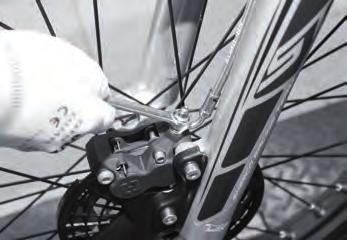
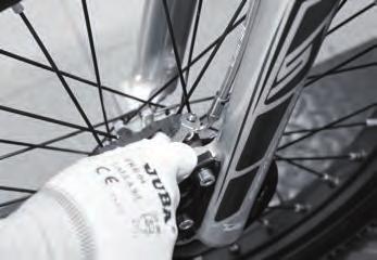
13 CHANGING FRONT FLEXIBLE BRAKE HOSE Loosen axle block nut Loosen and remove front axle Loosen the nuts that secure the discs, taking care not to damage the edges of the discs which may present burrs from the wear and tear. When assembling the discs, apply Loctite 243 to the screws in order to ensure greater adherence. ENGLISH Tighten the screws to 12NM using a dynamometric spanner. PARTS BREAKDOWN 135


14 STEERING SHAFT Dismantle handlebar securing fl anges. Turn the lower locknut clockwise 1/4 of a turn and then loosen the upper nut. Loosen the platen screws and release the suspension bars. Remove the lower nut. From the underside, release the steering shaft from its position in the chassis. Clean all parts. Check and replace the bearing if necessary. Before reassembling, lubricate with plenty of Minerva grease. Upon reassembling, once the upper platen is mounted, fi rst tighten the upper nut to 20NM and then lock it with the lower nut until the assembly is released and is able to turn freely and precisely. Use the marks to adjust the fi nal handlebar position. PARTS BREAKDOWN 136 ST SERIES


15 FRONT SUSPENSION Loosen the front bridge that joins the two suspension bars and the mudguard support. Remove the front wheel. Remove the front mudguard. Loosen the locking screws from the upper and lower platens. Release the front brake grasper. Cut the securing fl ange of the headlight bracket. Slide the bar along the underside. ENGLISH 137


16 CHANGING RIGHT SUSPENSION BAR SEAL Upon fi xing the bar on the bench, add a protective element to avoid erosion. Loosen the upper plug. Loosen the locknut. Hold the axle plug. Insert a tube in the axle drill and loosen the cartridge plug. Remove the cartridge locking screw and the oil retaining washer. Remove the cartridge from the bar. Turn the bar and remove the endofrun cone. Push the compression group inward and remove the circlip from its seat. Place the hydraulic group back in the cartridge. Insert the endofrun cone. 138 ST SERIES


17 CHANGING RIGHT SUSPENSION BAR SEAL Lever the edge of the dust cover and remove it from the bottle. Remove the circlip from its seat. Dismantle the bottle seal and cap. Apply grease to the bottle mouth to make assembly easier. ENGLISH PARTS BREAKDOWN 139


18 CHANGING LEFT SUSPENSION BAR SEAL Before fi xing the bar on the screw, use protective material to prevent scratching. Loosen the plug and remove it completely. Remove both tapered separators. Remove the washer and the spring slowly to avoid splashing oil. Place all the elements on a clean surface and empty the oil into a container. Secure the protected bottle and loosen the pumping die to be able to remove the oilretaining washer and screw. 140 ST SERIES


19 CHANGING LEFT SUSPENSION BAR SEAL Fully remove the pumping group. Invert the bar and remove the endofrun cone. Lever the edge of the dust cover and remove it from its seat on the bar. Remove the circlip from its seat. Secure the protected bar with the screw and slide the bottle until it is fully removed. Slide all parts indicated from the tube and replace part A. ENGLISH Grease the sleeve and seal seat before starting reassembly. Place the sleeve on its seat using the appropriate tools. Insert the washer, paying special attention to place its lip facing upward. Grease the tube with special sealing grease. 141


20 CHANGING LEFT SUSPENSION BAR SEAL Slide the dust cover down the bar turning slightly to fi nd its correct position on the bottle. Insert the pumping group with the endofrun cone ready mounted. While holding the tube at the end of its run with the help of the spring within the bar, fully tighten the pumping screw. Tighten the plug to NM using a dynamometric spanner. Position the bar vertically and pour in some of the new oil. Pump a few times, pushing the tube to the end of its run. Fill with oil up to 110mm from the brim. Insert the spring. Insert the separating washer. Insert the spacer. 142 ST SERIES

21 CHANGING LEFT SUSPENSION BAR SEAL Insert the tapered spacer. Fully tighten the upper plug of the tube to 17NM using a dynamometric spanner. PARTS BREAKDOWN ENGLISH 143


22 CARBURETTOR AND REED BLOCK Remove the rubber cap and cover from the throttle grip and release the cable. Open the cover and remove the air fi lter. Loosen the 2 screws fastening the fi lter box and the 3 screws from the rear mudguard. Remove the CDI and the clamps securing the carburettor to the inlet nozzles and fi lter. Close the fuel petcock valve. Remove the carburettor towards one side and dismantle the draining tube. 144 ST SERIES


.")


23 CARBURETTOR AND REED BLOCK Dismantle the fuel input tube. Open the upper cap and remove the sliding hood. This leaves the carburettor completely unfastened. On a clean table, loosen and remove the fl oat chamber by rotating it slightly. In an inverted position, test the height of the fl oats. (See fl oat height measures in the specifi c instructions). Reassemble the carburettor, inverting the dismantling process. ENGLISH Loosen the 4 M5 screws and remove the nozzle from the reed block. Check the height of the 5.5mm stoppers. The joint plane between the nozzle and the reed block must be 145


24 CARBURETTOR AND REED BLOCK perfect to avoid carburettor failure. If it is not, replace gasket ref: 5045 Reassemble the reed block. Reassemble the carburettor, connecting the tubes and assembling the fuel cable. Assemble the fi lter box. Position the carburettor and secure it with the fl anges. Place the air fi lter, the cover and the CDI. 146 ST SERIES
25 CARBURETTOR AND REED BLOCK 80c.c. 125 c.c. 250 c.c. 290 c.c. 300 c.c. Carburettor fl oat height Idle jet Main jet Needle position P3 P5 P2 +0.5(*) P4+0.5(*) P4+0.5(*) Dell orto P4 P3 P2 P1 P5 P4 P3 P2 P1 Keihin (*) 0.5mm PARTS BREAKDOWN ENGLISH Dell orto Keihin 147


26 CLUTCH PUMP The clutch pump can be changed with no need to dismantle the fl exible brake hose at the pump end. Remove the fl exible brake hose and the pump through the upper part of the chassis. PARTS BREAKDOWN 148 ST SERIES


27 RADIATOR Loosen and remove the radiator cap. Have a receptacle ready to collect the fl uid. Loosen and remove the cooling circuit draining screw. Empty the fl uid from the engine. Replace and close the draining screw. Release the sleeves. ENGLISH To change the radiator, loosen the 3 front fastening screws. PARTS BREAKDOWN 149


28 FOOTRESTS / ENGINE PROTECTOR Loosen the footrest shaftscrew. Check the condition of the spring and the sleeve. Clean and lubricate when reassembling. PARTS BREAKDOWN It is necessary to check the engine protector periodically, as well as its position and the condition of the rubber damper mounted between the protector and the engine carter. Ensure it is correctly positioned at its anchoring points. PARTS BREAKDOWN 150 ST SERIES


29 ELECTRICAL SYSTEM Most of the Sherco's electrical circuit is practically integrated into the chassis and only the connectors are visible. All the connection points,as well as the spark plug, coil, CDI, magnetic fl ywheel, and the ground anchoring point are accessed by dismantling the fi lter box. Lamp connectors plus switches Grounds High coil connections ENGLISH Flanged outlet of ignition cables CDI connector Regulator and rectifi er connections PARTS BREAKDOWN 151


30 CHANGING HEADLIGHT LEDs To release the headlight support plate, cut the supporting fl ange Disconnect the plate feed Separate the headlight plate with clearglass covering and the incorporated LEDs using the central fi xing screw. PARTS BREAKDOWN 152 ST SERIES


31 TILTING AXLE Loosen and remove the shaft. Check the condition of the sleeve and the bearings that are fi xed into the swivel itself. Check and replace if necessary. Use a pusher to remove the bearings. Place the shaft and correctly tighten the nut to 50NM. The tilting axle is one of the engine's main anchoring points. ENGLISH PARTS BREAKDOWN 153


32 REAR SUSPENSION To change the rear damper, it is necessary to dismantle the fi lter box, the rear mudguard and the muffl er to access the upper anchorage. Also loosen the anchorage from the group of lower connecting rods and the damper is free to be removed. The damper can also be removed from below by loosening the upper screw and dismantling the group of connecting rods. The connecting rod is forwarded. Check the condition of the sleeves and the bearings and replace them if necessary. Adequately grease the parts before reassembling them. PARTS BREAKDOWN 154 ST SERIES


33 REAR BRAKE AND TRANSMISSION MAINTENANCE Loosen the rear axle and remove the axle towards the left. Release the wheel from the chain so that it can easily be removed. Carry out maintenance operations on the rear brake, dismantling the brake pads and checking the height of the friction lining with the help of a calliper gauge. ENGLISH Remove the stoppers from both sides of the bushing in the wheel. Loosen the screws that hold the brake disc. 155


34 REAR BRAKE AND TRANSMISSION MAINTENANCE When reassembling the brake disc, apply Loctite 243 to the screws and tighten using a dynamometer. Whether the sprocket is changed or not, check that the securing screws are correctly tightened. Replace the wheel, taking care to place the bushing stoppers correctly, place the chain and center the wheel using the cams before fi nally tightening the axle. PARTS BREAKDOWN 156 ST SERIES


35 FUEL TANK With the fuel tank in view after dismounting the rear mudguard, remove the protector and loosen the securing screws. Slightly lift the tank to be able to manipulate and unhook the gas tubes connected to the gas pump. Always close the fuel petcock valve. ENGLISH PARTS BREAKDOWN 157


36 EXHAUST PIPE ASSEMBLY MAINTENANCE Open the cover and remove the air fi lter. Loosen and remove the screws, fastening the fi lter box and those of the rear mudguard. Loosen the screws that secure the exhaust pipe to the cylinder. Remove the exhaust collector. Loosen and remove the rear fastening screws of the fi lter box, as well as those of the muffl er protector and the tank. Loosen and remove the muffl er fastening screws in order to remove it. Invert the process to replace the muffl er. 158 ST SERIES
37 EXHAUST PIPE ASSEMBLY MAINTENANCE Apply lubricant to the collector to make it easier to assemble it with the muffl er. Assemble the collector and tighten the screws that join the collector to the cylinder. PARTS BREAKDOWN ENGLISH 159


38 CHANGING MUFFLER FIBRES Loosen and remove the muffl er's fastening screws in order to remove it, following the steps shown on page 36. Loosen the fastening screws of the muffl er cone. Remove the cone. Remove the inner tube and replace the fi bres. Place the new fi bres inside the muffl er, taking care not to obstruct the inner tube. Replace the removable part of the tube as well as the protective fastening cone. 160 ST SERIES

39 ENGINE PART ENGLISH 161

40 CHANGING THE PISTON Loosen and remove the radiator cap. Loosen and remove the cooling circuit draining screw. Have a receptacle ready to collect the fl uid. Empty the cooling fl uid from the engine. Replace and close the draining screw. Open the cover and remove the air fi lter. Loosen and remove the fi lter box's fastening screws as well as those of the rear mudguard. Loosen the rear mudguard. Remove the CDI 162 ST SERIES


41 CHANGING THE PISTON Loosen the clamps that secure the carburettor to the inlet nozzles and the fi lter box. Remove the fi lter box. Remove the spark plug. Loosen the screws from the joining beam between the cylinder head to the chassis. Disconnect the coil. ENGLISH Loosen and remove the coil bracket. Loosen the screws that secure the exhaust pipe to the cylinder. 163


42 CHANGING THE PISTON Remove the clamps from the sleeve of the cooling circuit that join the cylinder head to the radiator. Release the sleeve from the cylinder head. Loosen the screws and lift the cylinder head, paying attention not to damage the small oring seals. Loosen the screws that hold the cylinder and lift it. Remove the clips that fasten the bolt to the piston using pointed pliers. Remove the bolt by pushing with a special tool. Check the condition of the connecting rod ball bearing. Replace the gasket between the en 164 ST SERIES


43 CHANGING THE PISTON Lubricate the ends of the connecting rod and the roller bearings. Check the tolerance between piston and cylinder. See tolerance table. Prepare the piston with the compressed rings to be introduced into the cylinder. With the piston fi tted into the cylinder, insert the bolt into the piston without reaching the connecting rod's anchoring area. Align with the connecting rod and press the piston fully. Place the piston's securing clips, making sure they are correctly placed. Finish placing the cylinder in its fi nal position and tighten the cylinder's fastening screws with a dynamometer at 22NM. Check the height of the cylinder, piston and transfers. Prepare the cylinder head and its corresponding oring seals, making sure they are correctly located in the grooves. Place the 6 small oring seals. ENGLISH 165


44 CHANGING THE PISTON Tighten the cylinder head fastening screws using a dynamometer gauged at 11NM. Place and tighten the bracket joining the chassis to the cylinder head. Place the cooling circuit sleeves. Place and tighten the sleeve fastening clamps using specifi c pliers. Screw in the spark plug. Apply lubricant to the area where the exhaust pipe joins the muffl er in order to facilitate the connection. Place the exhaust pipe gasket and make sure it fi ts correctly. 166 ST SERIES


45 CHANGING THE PISTON Tighten the screws that anchor the exhaust pipe to the cylinder. Fill the cooling circuit with antifreezing fl uid (430cc). Place the cap on the radiator. PARTS BREAKDOWN ENGLISH 167


46 VERIFYING PISTON AND CYLINDER Use a palmer to verify the size of a piston. Check the nomenclature on the top of the piston depending on its tolerance. Measure the interior of the cylinder. Check between the two readings depending on the capacities. Check the tolerances in the technical specifi cations table. PARTS BREAKDOWN 168 ST SERIES


47 IGNITION Remove the drive sprocket circlip. Shift the pinion and chain assembly outward. Loosen and remove the gearshift lever. Loosen and remove the ignition cover. Check and gauge the pickup distance using a 0.71mm gauge. ENGLISH Loosen the rotor using special tool ref: R075. Remove the rotor and loosen the pickup. Loosen the stator and remove it. 169


48 IGNITION When replacing the stator, pay special attention to positioning and aligning the pickup before tightening the fastening screws. Once the fl ywheel has been replaced, impregnate the nut with Loctite 243 fastener and set the dynamometer to 100NM. Before replacing the cover, make sure the oring seal has been correctly placed on the cover. Replace the ignition cover. PARTS BREAKDOWN 170 ST SERIES


49 CLUTCH DISCS First remove the brake pedal. Loosen and remove the clutch cover screws. Loosen the clutch spring screws. Remove the springbearing plate. Pay attention to the position of the washer. Using a calliper gauge, check the wear and tear of the disc lining, max 2.6mm, min 2.4mm. Pay attention to how the discs are placed when reassembling and tightening the disc assembly. ENGLISH PARTS BREAKDOWN 171


50 START ROUTINE First see gear selector page 53 Remove the washer, the sleeve and the spring from its positioning hole in order to remove it. Remove the starter axle, remove the spring. Remove the washer and check sliding and wear and tear on the pawl and ratchet. Before assembling, check the axle and pawl are of the same brand. Lay out the pieces in the same order in which they were dismantled in order to facilitate the assembly process. 172 ST SERIES


51 START ROUTINE Incorporate the washers. Assemble the bearing and pawl pinion. Place the spring and washer in position. ENGLISH Place the clutch sleeve and bearing. Assemble the clutch bearing. Apply Loctite 243 to the nut. Tighten using special tool ref: R037 and 173


52 START ROUTINE the dynamometer adjusted to 50NM. Mount the discs, starting with a lined disc. Alternate 1 lined and 1 unlined disc. Complete the process by assembling the semicarter, screwing it in and mounting the starter lever. PARTS BREAKDOWN 174 ST SERIES


53 GEAR SELECTOR Loosen and remove the radiator. Loosen and remove the cooling circuit draining screw. Have a receptacle ready to collect the fl uid. Empty the cooling fl uid from the engine. Replace and close the draining screw. Loosen and remove the gearshift lever. Empty the oil from the engine carter. ENGLISH Dismantle the starter pedal. Loosen the screws from the engine's righthand semicarter. Remove the semicarter, including its cover. Loosen the clutch spring screws. After removing the cover with the springs, remove the clutch peg and rod. 175


54 GEAR SELECTOR Loosen the sprocket, remove the discs and dismantle the assembly. Pull back the scorpion and remove the axle. Check the alignment of the selector spring. PARTS BREAKDOWN 176 ST SERIES


55 GEARS AND CRANKSHAFT Dismantle the gearshift lever, the ignition box cover and the ignition system and pickup. Remove the circlip and then the drive sprocket. Dismantle the inlet nozzle. ENGLISH Loosen and remove the cylinder head. Loosen and remove the cylinder. 177


56 GEARS AND CRANKSHAFT Loosen the righthand side carter screws. Remove the carter and remove the centring devices and the gasket. Loosen the clutch. Dismantle the clutch and remove the clutch rod to be able to loosen the clutch housing. Remove the clutch housing and the selector shaft. 178 ST SERIES


57 GEARS AND CRANKSHAFT Loosen and remove toothed washer. Take care not to damage the needles. Remove the circlip and intermediary pinion. ENGLISH Loosen the primary transmission pinion. Remove the nut and washer. Remove the pinion using an extractor. Loosen and remove the carter screw plugs. Separate the two carters. 179


58 GEARS AND CRANKSHAFT Remove and put away the 2 centring devices. Remove the adjustment washers. Remove the axles from the forks. Remove the two upper forks. Remove the desmodromic drum and the third fork. Remove the complete gear pinion assembly. Dismantle the primary axle using the Knipey pliers. Repeat the operation with the secondary 180 ST SERIES


59 GEARS AND CRANKSHAFT axle. Keep the parts in the same order to make reassembly easier. PARTS BREAKDOWN ENGLISH 181


60 WATER PUMP Loosen and remove the radiator cap. Loosen and remove the cooling circuit draining screw. Have a receptacle ready to collect the fl uid. Empty the cooling fl uid from the engine. Replace and close the draining screw. Dismantle the starter pedal. Empty the oil from the engine carter. Loosen the screws of the engine's righthand semicarter. Remove the semicarter including its cover. Check the axle and make sure that the seal is leaktight. PARTS BREAKDOWN 182 ST SERIES
MKX 50 PRO MKX 50 BIGFOOT MKX 50 MONGOOSE
 MKX 50 PRO MKX 50 BIGFOOT MKX 50 MONGOOSE CHASSIS 1 81108001 PERIMETRAL ALUMINIUM CHASSIS MKX 1 2 81108002 FIXING BRACKET SET MKX ENGINE 2 3 81108003 FIXING SCREW MKX ENGINE 2 4 81108004 RIGHT FOOTREST
SSR200 Zongshen 200cc Dirt Bike (VIN PREVIX LZSJ)
") Page 1 of 19 Product Information Baja Web > Product Information > Parts Lists > DIRTBIKE > SSR200 Zongshen 200cc Dirt Bike (VIN PREVIX LZSJ) SSR200 Zongshen 200cc Dirt Bike (VIN PREVIX LZSJ) SSR200 Zongshen
Page 1 of 19 Product Information Baja Web > Product Information > Parts Lists > DIRTBIKE > SSR200 Zongshen 200cc Dirt Bike (VIN PREVIX LZSJ) SSR200 Zongshen 200cc Dirt Bike (VIN PREVIX LZSJ) SSR200 Zongshen
CHASSIS CONTENTS EXTERIOR PARTS 6-1 FRAME COVER 6-2 REAR FRAME COVER 6-4 FRONT WHEEL 6-6 FRONT BRAKE 6-10 HANDLEBARS 6-17 FRONT FORK 6-19
 CHASSIS CONTENTS EXTERIOR PARTS 6- FRAME COVER 6- REAR FRAME COVER 6-4 FRONT WHEEL 6-6 FRONT BRAKE 6-0 HANDLEBARS 6-7 FRONT FORK 6-9 STEERING 6-6 REAR WHEEL 6-3 REAR BRAKE 6-39 6 REAR SHOCK ABSORBER 6-43
ATV 50 DVX BLACK-RED (A2008KSA2BUSD) Page 1 of 60 AIR INTAKE ASSEMBLY
 Page 1 of 60 AIR INTAKE ASSEMBLY") 2008 ATV 50 DVX BLACK-RED (A2008KSA2BUSD) Page 1 of 60 AIR INTAKE ASSEMBLY 2008 ATV 50 DVX BLACK-RED (A2008KSA2BUSD) Page 2 of 60 AIR INTAKE ASSEMBLY Ref # Part Number Qty S/P/F Description 1 3303-005
2008 ATV 50 DVX BLACK-RED (A2008KSA2BUSD) Page 1 of 60 AIR INTAKE ASSEMBLY 2008 ATV 50 DVX BLACK-RED (A2008KSA2BUSD) Page 2 of 60 AIR INTAKE ASSEMBLY Ref # Part Number Qty S/P/F Description 1 3303-005
SMF / DSF / DTF SMF / DSF / DTF 200
 2006 SMF / DSF / DTF 200 1 The drawings in this parts book have been scaled so that parts can be easily recognized. 1 CYLINDER ASSY 2 CYLINDER ASSY Ref # Part # Description 1 410 0001A CYLINDER HEAD COVER
ATV 90 UTILITY GREEN (A2006KUB2BUSG) Page 1 of 60 AIR INTAKE ASSEMBLY
 Page 1 of 60 AIR INTAKE ASSEMBLY") 2006 ATV 90 UTILITY GREEN (A2006KUB2BUSG) Page 1 of 60 AIR INTAKE ASSEMBLY 2006 ATV 90 UTILITY GREEN (A2006KUB2BUSG) Page 2 of 60 AIR INTAKE ASSEMBLY Ref # Part Number Qty S/P/F Description 1 3303-005
2006 ATV 90 UTILITY GREEN (A2006KUB2BUSG) Page 1 of 60 AIR INTAKE ASSEMBLY 2006 ATV 90 UTILITY GREEN (A2006KUB2BUSG) Page 2 of 60 AIR INTAKE ASSEMBLY Ref # Part Number Qty S/P/F Description 1 3303-005
ATV 50 Y-6 YOUTH CAT GREEN (A2004ATA2BUSZ) Page 1 of 50 A-ARM, FLOOR PANEL, AND BUMPER ASSEMBLY
 Page 1 of 50 A-ARM, FLOOR PANEL, AND BUMPER ASSEMBLY") 2004 ATV 50 Y-6 YOUTH CAT GREEN (A2004ATA2BUSZ) Page 1 of 50 A-ARM, FLOOR PANEL, AND BUMPER ASSEMBLY 2004 ATV 50 Y-6 YOUTH CAT GREEN (A2004ATA2BUSZ) Page 2 of 50 A-ARM, FLOOR PANEL, AND BUMPER ASSEMBLY
2004 ATV 50 Y-6 YOUTH CAT GREEN (A2004ATA2BUSZ) Page 1 of 50 A-ARM, FLOOR PANEL, AND BUMPER ASSEMBLY 2004 ATV 50 Y-6 YOUTH CAT GREEN (A2004ATA2BUSZ) Page 2 of 50 A-ARM, FLOOR PANEL, AND BUMPER ASSEMBLY
Master Part List SY250. Rev. 1
 Rev. 1 1-1015 Frame 1 1 1 1 1-1017 Frame 1 2-1021 Guard, engine 1 1 1 1 1 1 3-1044 Foot Rest, right side 1 1 1-1045 Foot Rest, right side 1 - S1A-20202-00-00 Foot Rest, right side steel 1 1 4-1054 Foot
View Catalogs Online at
 ML125-5 Frame Parts 12551-1 Grip, LH 12551-2 Front Brake Lever Comp. 12551-3 Handlebar Switch, LH 12551-4 Rearview Mirror, LH 12551-5 Rearview Mirror, RH 12551-6 Handlebar Switch, RH 12551-7 Clutch Lever
X4 (GREEN) (A2000ATF2AUSG) Page 1 of 80 AIR INTAKE ASSEMBLY
 (A2000ATF2AUSG) Page 1 of 80 AIR INTAKE ASSEMBLY") 2000 300 2X4 (GREEN) (A2000ATF2AUSG) Page 1 of 80 AIR INTAKE ASSEMBLY 2000 300 2X4 (GREEN) (A2000ATF2AUSG) Page 2 of 80 AIR INTAKE ASSEMBLY Ref # Part Number Qty S/P/F Description 1 3570-001 1 /P Intake,
2000 300 2X4 (GREEN) (A2000ATF2AUSG) Page 1 of 80 AIR INTAKE ASSEMBLY 2000 300 2X4 (GREEN) (A2000ATF2AUSG) Page 2 of 80 AIR INTAKE ASSEMBLY Ref # Part Number Qty S/P/F Description 1 3570-001 1 /P Intake,
90 Utility Model Number A2013KUB2BUSZ SHARE OUR PASSION.
 2013 90 Utility Model Number A2013KUB2BUSZ TM SHARE OUR PASSION. TABLE OF CONTENTS 2013 ATV 90 (Model No. A2013KUB2BUSZ) BODY PANEL AND HEADLIGHT ASSEMBLY... 1 FRONT AND REAR RACK ASSEMBLY... 2 FRAME AND
Technical data. Part Thread (mm) Nm ±10% Tolerance Sidestand
 Nm ±10% Tolerance Sidestand") section 3 - Torque settings Frame torque settings Sidestand Stand sensor bolt 5 Pre-applied threadlocker Stand plate fixing screw M10x25 43 Pre-applied threadlocker Side stand fastening pin Side stand
section 3 - Torque settings Frame torque settings Sidestand Stand sensor bolt 5 Pre-applied threadlocker Stand plate fixing screw M10x25 43 Pre-applied threadlocker Side stand fastening pin Side stand
CYLINDER. Ref. Part No. Number Description Qty Remarks
 A1 A2 A3 A4 CYLINDER 1 2GU-11111-00-00 HEAD, CYLINDER 1......... 1 2 NGK-B8ES0-00-00 PLUG, SPARK (NGK B8ES)... 2 3 90116-08394-00 BOLT, STUD.............. 8 4 95917-08640-00 BOLT, STUD.............. 2
View Catalogs Online at
 Catalog ML125-5 2015Edition ML125-5 Frame Parts 12551-1 Grip, LH 12551-2 Clutch Lever Comp. 12551-3 Handlebar Switch, LH 12551-4 Rearview Mirror, LH 12551-5 Rearview Mirror, RH 12551-6 Handlebar Switch,
B B B
 FIG CYLINDER Suzuki Worldwide Motorcycle-ATV Page: of -0B00-00 0-00 0-000 0-00 0-0B0-0B0 0-0 0-0 Head, Cylinder Gasket, Cylinder Head Spark Plug (ngk,bphs) Spark Plug (nd,wfp-u) Cylinder Gasket, Cylinder
ATV 90 UTILITY CALIFORNIA GREEN (A2008KUB2BCAG) Page 1 of 58 AIR INTAKE ASSEMBLY
 Page 1 of 58 AIR INTAKE ASSEMBLY") 2008 ATV 90 UTILITY CALIFORNIA GREEN (A2008KUB2BCAG) Page 1 of 58 AIR INTAKE ASSEMBLY 2008 ATV 90 UTILITY CALIFORNIA GREEN (A2008KUB2BCAG) Page 2 of 58 AIR INTAKE ASSEMBLY Ref # Part Number Qty S/P/F Description
2008 ATV 90 UTILITY CALIFORNIA GREEN (A2008KUB2BCAG) Page 1 of 58 AIR INTAKE ASSEMBLY 2008 ATV 90 UTILITY CALIFORNIA GREEN (A2008KUB2BCAG) Page 2 of 58 AIR INTAKE ASSEMBLY Ref # Part Number Qty S/P/F Description
SERVICE MANUAL 1 A EDITION w w w. m o t o r h i s p a n i a. e s
 SERVICE MANUAL REF. OF PUBLICATION: 0634111000004 1 A EDITION 2007-10 USE THIS SERVICE MANUAL WITH THE RELATED MANUALS INDICATED IN THE FOREWORD TO THIS MANUAL w w w. m o t o r h i s p a n i a. e s IMPORTANT
Part list for Kawasaki H2, 1972
 Part list for Kawasaki H2, 972 . Cylinder head, cylinder. . Cylinder head, cylinder. 9205-049 NUT 0 m/m 2 2 40B400 WASHER-plain 4 m/m 2 3 46E400 WASHER-spring 4 m/m 2 4 92070-036 SPARK PLUG NGK B9 HS 3
CYLINDER HEAD CONTINUED ON NEXT FRAME. Ref. Part No. Number Description Qty Remarks
 A1 CYLINDER HEAD 1 4JY-11111-00-00 HEAD, CYLINDER 1 (4JY-11111-01-00).......... 1 2 90116-08394-00 BOLT, STUD.............. 5 3 90176-08026-00 NUT, CROWN............. 5 4 90201-08087-00 WASHER, PLATE...........
DVX 90 MODEL NUMBER A2008KSB2BUSD (BLACK-RED) MODEL NUMBER A2008KSB2BUSE (BLACK-CAT GREEN) MORE TO GO ON. TM
 MODEL NUMBER A2008KSB2BUSE (BLACK-CAT GREEN) MORE TO GO ON. TM") 2008 DVX 90 Illustrated Parts Manual MODEL NUMBER A2008KSB2BUSD (BLACK-RED) MODEL NUMBER A2008KSB2BUSE (BLACK-CAT GREEN) MORE TO GO ON. TM TABLE OF CONTENTS Black-Red (Model No. A2008KSB2BUSD) Black-Cat
2008 DVX 90 Illustrated Parts Manual MODEL NUMBER A2008KSB2BUSD (BLACK-RED) MODEL NUMBER A2008KSB2BUSE (BLACK-CAT GREEN) MORE TO GO ON. TM TABLE OF CONTENTS Black-Red (Model No. A2008KSB2BUSD) Black-Cat
CHASSIS CONTENTS EXTERIOR PARTS 6-1 FRONT WHEEL 6-2 FRONT BRAKE 6-6 HANDLEBARS 6-12 REAR WHEEL 6-30 REAR BRAKE 6-34 REAR SHOCK ABSORBER 6-36
 CHASSIS CONTENTS EXTERIOR PARTS 6-1 FRONT WHEEL 6-2 FRONT BRAKE 6-6 HANDLEBARS 6-12 FRONT FORK ( ) 6-14 FRONT FORK ( ) 6-20 STEERING 6-27 REAR WHEEL 6-30 REAR BRAKE 6-34 REAR SHOCK ABSORBER 6-36 6 SWING
CYLINDER HEAD CONTINUED ON NEXT FRAME. Ref. Part No. Number Description Qty Remarks
 A1 CYLINDER HEAD 1 4JY-11111-00-00 HEAD, CYLINDER 1 (4JY-11111-01-00).......... 1 2 90116-08394-00 BOLT, STUD.............. 5 3 90176-08026-00 NUT, CROWN............. 5 4 90201-08087-00 WASHER, PLATE...........
CYLINDER. Ref. Part No. Number Description Qty Remarks
 A1 CYLINDER 1 2GU-11111-00-00 HEAD, CYLINDER 1......... 1 2 NGK-B8ES0-00-00 NGK B8ES 10PK........... 2 3 90116-08394-00 BOLT, STUD.............. 8 4 95912-08640-00 BOLT, STUD.............. 2 5 90179-08491-00
X150 National Extreme 150cc Atv (VIN PREFIX RKKG)
") Page 1 of 25 Product Information Baja Web > Product Information > Parts Lists > ATV > X150 National Extreme 150cc Atv (VIN PREFIX RKKG) X150 National Extreme 150cc Atv (VIN PREFIX RKKG) Cylinder Head [Image]
Page 1 of 25 Product Information Baja Web > Product Information > Parts Lists > ATV > X150 National Extreme 150cc Atv (VIN PREFIX RKKG) X150 National Extreme 150cc Atv (VIN PREFIX RKKG) Cylinder Head [Image]
ATV 300 DVX CAT GREEN (A2011KSF2BUSZ) Page 1 of 56 AIR INTAKE ASSEMBLY
 Page 1 of 56 AIR INTAKE ASSEMBLY") 2011 ATV 300 DVX CAT GREEN (A2011KSF2BUSZ) Page 1 of 56 AIR INTAKE ASSEMBLY 2011 ATV 300 DVX CAT GREEN (A2011KSF2BUSZ) Page 2 of 56 AIR INTAKE ASSEMBLY Ref # Part Number Qty S/P/F Description 1 3303-705
2011 ATV 300 DVX CAT GREEN (A2011KSF2BUSZ) Page 1 of 56 AIR INTAKE ASSEMBLY 2011 ATV 300 DVX CAT GREEN (A2011KSF2BUSZ) Page 2 of 56 AIR INTAKE ASSEMBLY Ref # Part Number Qty S/P/F Description 1 3303-705
PARTS CATALOGUE. Rockford Motors inc.
 PARTS CATALOGUE Rockford Motors inc. INSTRUCTIONS FOR USING THE PARTS CATALOGUE 1. This catalogue covers all the items of genuine parts and tools of BRIDGESTONE 350 GTR and 350 GTO motorcycles. 2. Please
TRIAL. Brochure I 125 I 250 I 290 I 305
 TRIAL Brochure 2013 80 I 125 I 250 I 290 I 305 80/125 Refined Carburetor Improved clutch New abrasion resistant decals New "Formula" brand brake system Small heart, great performance 80/125 125 15125 125
11/14/ U. Baja Motorsports Inc. P.O. Box Phoenix, AZ Toll Free: PARTS AND PRICES ARE SUBJECT TO CHANGE 1 of 53
 250U Toll Free: 888-863-2252 PARTS AND PRICES ARE SUBJECT TO CHANGE 1 of 53 FIG. 1 PNEUMATIC MECHANISM 1-1 250U-100 883099019951 CAMSHAFT 1 1 1-2 250U-101 883099019968 KEY, WOODRUFF 1 1 1-3 250U-102 883099019975
Description. Copyright 2005 Suzuki Worldwide Motorcycle-ATV. All Rights Reserved.
 LT0K (LT0K P) FIG GASKET SET Suzuki Worldwide Motorcycle-ATV Page: of 0 0-0 -00-0B0-0B0 -A0 -E00-000 -0B0 0-000 0-000 0-00 00-00 00-00 00-00 Gasket Set Gasket, Cylinder Head Gasket, Cylinder Gasket, Clutch
ATV I l. l u. r a. Parts Manual ARCTIC CAT. 250 cc/300 cc
 2000 I l l u st ATV 250 cc/300 cc Model No. A2000ATE2AUSG (250 - Green) Model No. A2000ATE2AUSR (250 - Red) Model No. A2000ATF2AUSG (300 2x4 - Green) Model No. A2000ATF2AUSR (300 2x4 - Red) Model No. A2000ATF4AUSG
DVX 300 Euro. Model Number A2012KSF2BEUK SHARE OUR PASSION.
 ATV 2012ATV Illustrated Parts Manual DVX 300 Euro Model Number A2012KSF2BEUK TM SHARE OUR PASSION. TABLE OF CONTENTS 2012 ATV DVX 300 Euro (Model No. A2012KSF2BEUK) BODY PANEL AND HEADLIGHT ASSEMBLY...
CHASSIS CONTENTS FRONT WHEEL 6-1 FRONT BRAKE 6-6 FRONT FORK 6-14 STEERING STEM 6-20 REAR WHEEL AND REAR BRAKE 6-25 SUSPENSION 6-31 REAR SWING ARM 6-36
 CHASSIS CONTENTS FRONT WHEEL 6-1 FRONT BRAKE 6-6 FRONT FORK 6-14 STEERING STEM 6-20 REAR WHEEL AND REAR BRAKE 6-25 SUSPENSION 6-31 REAR SWING ARM 6-36 6 6-1 CHASSIS FRONT WHEEL REMOVAL Support the machine
WORKSHOP MANUAL TECHNICAL NETWORK LEADERSHIP WORKSHOP MANUAL 125 CC/150 CC 4-STROKE ENGINE
 WORKSHOP MANUAL TECHNICAL NETWORK LEADERSHIP WORKSHOP MANUAL - 5 CC/50 CC 4-STROKE ENGINE Workshop manual Technical network leadership TABLE OF CONTENTS TABLE OF CONTENTS TABLE OF CONTENTS... CHARACTERISTICS...
CYLINDER - CYLINDER HEAD
 A1 CYLINDER - CYLINDER HEAD 1 3FA-11110-00-00 CYLINDER HEAD ASSEMBLY. 1 2 95612-06625-00. BOLT, STUD............. 2 3 22F-11134-10-00. GUIDE, EXHAUST VALVE... 2 4 93440-10109-00. CIRCLIP.................
CYLINDER HEAD. Ref. Part No. Number Description Qty Remarks
 A1 A2 A3 A4 CYLINDER HEAD 1 1UY-11110-02-00 CYLINDER HEAD ASSY...... 1 2 3Y1-11133-11-00. GUIDE, INTAKE VALVE..... 2 3 93440-12052-00. CIRCLIP................. 2 4 90401-06001-00. BOLT, UNION............
BikeSelection ML100-A ML125-7 LF150-7 LF250GY-4 ML200-16D ML250-4 ML200ZH-3
 M EILUN M OTORCYCLE PARTS ML200-16D 2018Edition BikeSelection ML100-A LF110-7A LF1200DT ML125-5 ML125-7 ML125T-26 LF150-7 LF150GY-3B LF200GY-4 LF250GY-4 LF150-10F LF150-10S ML200-16D ML250-4 ML200ZH-3
CYLINDER HEAD. Ref. Part No. Number Description Qty Remarks
 A1 A2 A3 A4 CYLINDER HEAD 1 3FA-11110-01-00 CYLINDER HEAD ASSY...... 1 2 90116-06541-00. BOLT, STUD............. 2 3 22F-11134-10-00. GUIDE, EXHAUST VALVE... 2 4 93440-10109-00. CIRCLIP.................
CHASSIS CONTENTS EXTERIOR PARTS 7-1 FRONT WHEEL 7-2 FRONT BRAKE 7-6 HANDLEBARS 7-13 FRONT FORK 7-15 STEERING 7-23 REAR WHEEL 7-26 REAR BRAKE 7-30
 CHASSIS CONTENTS EXTERIOR PARTS 7- FRONT WHEEL 7-2 FRONT BRAKE 7-6 HANDLEBARS 7-3 FRONT FORK 7-5 STEERING 7-23 REAR WHEEL 7-26 REAR BRAKE 7-30 REAR SHOCK ABSORBER 7-32 SWING ARM 7-33 7 7- CHASSIS EXTERIOR
INDEX REAR SHOCK ABSORBER REAR FENDER HANDLE SWITCH
 2005 / 2006 DTF 150 INDEX ENGINE FRAME SECTION FIG # SECTION FIG # CYLINDER HEAD E01 HANDLE BAR F01 CYLINDER E02 STEERING STEM F02 RIGHT CRANKCASE E03 FRONT FENDER F03 RIGHT CRANKCASE 2 E04 FRONT FORK
Illustrated Parts Manual. Model Number A2011KSF2BEUZ (Black-Cat Green) A2011KSF2BEOJ (White-Cat Green)
 A2011KSF2BEOJ (White-Cat Green)") Illustrated Parts Manual 2 1 10 DVX 300 Euro Model Number A2011KSF2BEUZ (Black-Cat Green) A2011KSF2BEOJ (White-Cat Green) S H A R E O U R PAS S IO N. TM TABLE OF CONTENTS 2011 ATV DVX 300 Euro Black-Cat
Illustrated Parts Manual 2 1 10 DVX 300 Euro Model Number A2011KSF2BEUZ (Black-Cat Green) A2011KSF2BEOJ (White-Cat Green) S H A R E O U R PAS S IO N. TM TABLE OF CONTENTS 2011 ATV DVX 300 Euro Black-Cat
5/29/2014 3MSHY 2000 / CYLINDER CRANKCASE Yamaha Motor Corporation, U.S.A. All rights reserved.
 Page 1 of 22 3MSHY 2000 / CYLINDER CRANKCASE Page 2 of 22 Part List 3MSHY 2000 / CYLINDER CRANKCASE REF - NO PART NUMBER PART NAME QUANTITY REMARKS 1 6L5-W0090-01-1S CRANK CYLINDER ASSY 1 2 6L5-15100-00-1S
5/29/2014 3MSHU 1996 / CYLINDER CRANKCASE Yamaha Motor Corporation, U.S.A. All rights reserved.
 Page 1 of 22 3MSHU 1996 / CYLINDER CRANKCASE Page 2 of 22 Part List 3MSHU 1996 / CYLINDER CRANKCASE REF - NO PART NUMBER PART NAME QUANTITY REMARKS 1 6L5-W0090-01-4D CRANK CYLINDER ASSEMBLY 1 2 6L5-15100-00-94
MicrofichesExcel. Tavola Posizione Codice Quant Ing
 Tavola Posizione Codice Quant Ing 1 1 T1P52MI-A-011200 1 LH Crankcase 1 2 T1P52MI-A-011300 1 RH Crankcase 1 3 T11119 1 Crankcase gasket 1 4 TOR00037 4 Screw M5 6 1 5 T1P52MI-011400 2 Bush 1 6 T11118 2
Parts Diagrams RR/RS Models
 Parts Diagrams 2008-2009 RR/RS Models Table Of Contents Description Page # front fork 1 handlebar, clutch pump, meter (RR Models) 2 handlebar, clutch pump, meter (RS Models) 3 frame, subframe 4 rear shock,
XC 450 EFT Model Number A2013KCK4CETT SHARE OUR PASSION.
 2013 XC 450 EFT Model Number A2013KCK4CETT TM SHARE OUR PASSION. TABLE OF CONTENTS 2013 XC 450 EFT Green (Model No. A2013KCK4CETT) FRONT BODY ASSEMBLY... 1 REAR BODY AND TAILLIGHT ASSEMBLY... 2 BUMPER,
 Honda 1975 Parts List ENGINE GROUP Block Ref. 1F 1 11000-377-000 CRANKCASE ASSY. 1 2F 2 11208-333-000 CAP, OIL PATH 1 2F 3 11210-377-000 PAN, OIL 1 2F 4 11291-377-000 PLUG, OIL PATH 1 1E 5 11331-377-000
CYLINDER. Ref. Part No. Number Description Qty Remarks
 A1 CYLINDER 1 3R9-11111-00-00 HEAD, CYLINDER 1......... 1 2 1W2-11161-00-00 ABSORBER 1............. 2 3 (1W2-11127-00-00) ABSORBER 3............. 1 4 2X3-11181-00-00 GASKET, CYLINDER HEAD 1. 1 5 90116-08321-00
View Catalogs Online at
 ML150-9J Frame Parts 15091-1 Front Fairing Plate 15091-2BU Front Fairing - Blue 15091-2R Front Fairing - Red 15091-3 Front Windshield 15091-4 Headlight Assy 15091-5 Headlight Bulb 12V/35W 15091-6 Parking
Unit: mm (in) ITEM STANDARD LIMIT IN. 33 (1.3) EX.
 ITEM STANDARD LIMIT IN. 33 (1.3) EX.") Model: DR650SEL0 E-03, 24, 28, 33 Date: July 16, 2009 SERVICE DATA VALVE + GUIDE Valve diam. Valve clearance (when engine is cold) Valve guide to valve stem clearance Valve stem deflection Valve guide
Model: DR650SEL0 E-03, 24, 28, 33 Date: July 16, 2009 SERVICE DATA VALVE + GUIDE Valve diam. Valve clearance (when engine is cold) Valve guide to valve stem clearance Valve stem deflection Valve guide
CYLINDER HEAD CONTINUED ON NEXT FRAME. Ref. Part No. Number Description Qty Remarks
 A1 A2 A3 A4 CYLINDER HEAD 1 3TB-11101-02-00 CYLINDER HEAD ASSY...... 1 2 4H7-11133-10-00. GUIDE, INTAKE VALVE..... 4 3 93440-12052-00. CIRCLIP................. 4 4 90116-06475-00. BOLT, STUD.............
9/7/2014 T9.9ELRZ 2001 / TOP COWLING Yamaha Motor Corporation, U.S.A. All rights reserved.
 T9.9ELRZ 00 Page of 56 9/7/0 T9.9ELRZ 00 / TOP COWLING 0 Yamaha Motor Corporation, U.S.A. All rights reserved. T9.9ELRZ 00 Page of 56 9/7/0 Part List T9.9ELRZ 00 / TOP COWLING REF - NO PART NUMBER PART
400 4x4 Euro MODEL NUMBER A2008IDG4BEUR (RED) MODEL NUMBER A2008IDG4BEUG (GREEN) MODEL NUMBER A2008IDG4BEUZ (CAT GREEN) MORE TO GO ON.
 MODEL NUMBER A2008IDG4BEUG (GREEN) MODEL NUMBER A2008IDG4BEUZ (CAT GREEN) MORE TO GO ON.") 2008 400 4x4 Euro Illustrated Parts Manual MODEL NUMBER A2008IDG4BEUR (RED) MODEL NUMBER A2008IDG4BEUG (GREEN) MODEL NUMBER A2008IDG4BEUZ (CAT GREEN) MORE TO GO ON. TM TABLE OF CONTENTS 2008 ATV 400 4x4
2008 400 4x4 Euro Illustrated Parts Manual MODEL NUMBER A2008IDG4BEUR (RED) MODEL NUMBER A2008IDG4BEUG (GREEN) MODEL NUMBER A2008IDG4BEUZ (CAT GREEN) MORE TO GO ON. TM TABLE OF CONTENTS 2008 ATV 400 4x4
PARTS LIST ATV250 - SHAFT DRIVE
 PARTS LIST ATV250 - SHAFT DRIVE REF. NO DESCRIPTION PRICE FIG. 1 PNEUMATIC MECHANISM ATV250-1-1 PNEUMATIC CAM SHAFT ASSY 133.28 ATV250-1-2 column pin 2.40 ATV250-1-3 Roll bearing 19.36 ATV250-1-4 Roll
Indicates a potential hazard that could result in death or injury. Indicates a potential hazard that could result in motorcycle damage.
 FOREWORD This motorcycle has been designed and produced utilizing Suzuki s most modern technology. The finest product, however, cannot perform properly unless it is correctly assembled and serviced. This
9/7/2014 F9.9MSHV 1997 / CYLINDER CRANKCASE Yamaha Motor Corporation, U.S.A. All rights reserved.
 F9.9MSHV 997 Page of 45 9/7/04 F9.9MSHV 997 / CYLINDER CRANKCASE 04 Yamaha Motor Corporation, U.S.A. All rights reserved. F9.9MSHV 997 Page of 45 9/7/04 Part List F9.9MSHV 997 / CYLINDER CRANKCASE REF
90 Y-12 Youth. Model Number A2005H4B2BUSR (Red) Model Number A2005H4B2BUSZ (Cat Green) Illustrated Parts Manual
 Model Number A2005H4B2BUSZ (Cat Green) Illustrated Parts Manual") 90 Y-12 Youth Model Number A2005H4B2BUSR (Red) Model Number A2005H4B2BUSZ (Cat Green) Illustrated Parts Manual 2005 TABLE OF CONTENTS 2005 ATV 90 Y-12 Youth Red (Model No. A2005H4B2BUSR) Cat Green (Model
90 Y-12 Youth Model Number A2005H4B2BUSR (Red) Model Number A2005H4B2BUSZ (Cat Green) Illustrated Parts Manual 2005 TABLE OF CONTENTS 2005 ATV 90 Y-12 Youth Red (Model No. A2005H4B2BUSR) Cat Green (Model
CYLINDER 11/14/2008. Item No.
 WD90S Toll Free: 888-863-2252 (BAJA) PARTS AND PRICES ARE SUBJECT TO CHANGE 1 of 41 CYLINDER Part UPC Number Description 1 WD90S-100 883099036699 GASKET, CYLINDER BLOCK 1 1 2 WD90S-101 883099036743 DOWEL
2 TEMPS 125 ST 250 ST 300 ST
 SPEC SHEET Engine 2 TEMPS 125 ST 250 ST 300 ST 2 strokes Sherco proprietary design Engine Size 123.70 cc (7.55 cu in) 249.70 cc (15.24 cu in) 294 cc (17.94 cu in) Bore x stroke Cylinder 54 x 54 mm (2.13
Figure 1. - Cylinder / Cylinder Head
 Page 1 of 42 Figure 1. - Cylinder / Cylinder Head Figure 1. Cylinder / Cylinder Head 1 11111-STG-00 Cylinder comp 1 2 11121-STG-00 Head comp, cylinder 1 3 11127-CHP-00 Nut, cylinder head 1 4 11141-ROA-00
Valve + Valve Guide Unit: mm (in) Item Standard Limit Valve diam. IN (1.20) EX (1.06) Valve clearance (when cold)
 Item Standard Limit Valve diam. IN (1.20) EX (1.06) Valve clearance (when cold)") Model: LT-A400FL9 P-17, 24, 28,03 Date: Feb. 12, 2018 SERVICE DATA Valve + Valve Guide Valve diam. IN. 30.6 (1.20) EX. 27.0 (1.06) Valve clearance (when cold) IN. 0.05 0.10 (0.002 0.004) EX. 0.22 0.27
Model: LT-A400FL9 P-17, 24, 28,03 Date: Feb. 12, 2018 SERVICE DATA Valve + Valve Guide Valve diam. IN. 30.6 (1.20) EX. 27.0 (1.06) Valve clearance (when cold) IN. 0.05 0.10 (0.002 0.004) EX. 0.22 0.27
9/9/2014 F15MSHC 2004 / TOP COWLING Yamaha Motor Corporation, U.S.A. All rights reserved.
 F5MSHC 00 Page of 6 9/9/0 F5MSHC 00 / TOP COWLING 0 Yamaha Motor Corporation, U.S.A. All rights reserved. F5MSHC 00 Page of 6 9/9/0 Part List F5MSHC 00 / TOP COWLING REF - NO PART NUMBER PART NAME QUANTITY
G85CS Parts list. Frank Kyul, Netherlands
 G85CS Parts list Frank Kyul, Netherlands http://home.wanadoo.nl/fxkuyl/ CYLINDER BARREL & HEAD 022298 Barrel Cylinder 1 022515 Washer Cylinder Base 1 015351 Nut. Sleeve Cylinder Head 4 042157 Washer Sleeve
400 2x4/4x4 EFT SHARE OUR PASSION ṬM
 SHARE OUR PASSION ṬM 400 2x4/4x4 EFT Model Number A2009IDG2BETR (Red - 2x4) Model Number A2009IDG2BETZ (Cat Green - 2x4) Model Number A2009IDG4BETR (Red - 4x4) Model Number A2009IDG4BETG (Green - 4x4)
SERVICE DATA POWER PRUNER ECHO: PPF-300ES ECHO: PPT-300ES. (Serial number : and after) CONTENTS INTRODUCTION
 CONTENTS INTRODUCTION") 17-28A-00, 1 1 SERVICE DATA We are constantly working on technical improvement of our products. For this reason, technical data, equipment and design are subject to change without notice. All specifications
17-28A-00, 1 1 SERVICE DATA We are constantly working on technical improvement of our products. For this reason, technical data, equipment and design are subject to change without notice. All specifications
MAINTENANCE SXV / RXV
 MAINTENANCE SXV / RXV 450-550 3.1.12. HANDLEBAR AND CONTROLS Screw securing clutch control to handlebar M6 10 Throttle control screw M6 4 Ignition switch screw M8 24 FOOTRESTS Footrest support bracket

9/8/ MSHZ 2001 / TOP COWLING Yamaha Motor Corporation, U.S.A. All rights reserved.
 9.9MSHZ 00 Page of 47 9/8/04 9.9MSHZ 00 / TOP COWLING 04 Yamaha Motor Corporation, U.S.A. All rights reserved. 9.9MSHZ 00 Page of 47 9/8/04 Part List 9.9MSHZ 00 / TOP COWLING REF - NO PART NUMBER PART
CYLINDER HEAD CONTINUED ON NEXT FRAME. Ref. Part No. Number Description Qty Remarks
 A1 A2 A3 A4 CYLINDER HEAD 1 4BD-11101-02-00 CYLINDER HEAD ASSY...... 1 2 93440-10085-00. CIRCLIP................. 2 3 90153-06029-00. SCREW, HEXAGON........ 1 4 90430-06014-00. GASKET................ 1
REEDSTER 125cc. versions: F1 - F2 - F3 - F4 OVERHAULING MANUAL
 REEDSTER 125cc versions: F1 - F2 - F3 - F4 OVERHAULING MANUAL 07/11/07 21/01/2009 1 INDEX Page 1. - REEDSTER 125cc ENGINE DISASSEMBLY 1 2. - CRANKSHAFT DISASSEMBLY / ASSEMBLY 13 2.1 - CRANKSHAFT DISASSEMBLY
SERVICE DATA TRIMMER/BRUSHCUTTER ECHO: SRM-236ES STAGE MODEL. (Serial number : and after) INTRODUCTION CONTENTS
 INTRODUCTION CONTENTS") 10-21V-00 SRM-236ES 1 * 1 SERVICE DATA TRIMMER/BRUSHCUTTER ECHO: SRM-236ES STAGE MODEL (Serial number : 37000001 and after) INTRODUCTION We are constantly working on technical improvement of our products.
10-21V-00 SRM-236ES 1 * 1 SERVICE DATA TRIMMER/BRUSHCUTTER ECHO: SRM-236ES STAGE MODEL (Serial number : 37000001 and after) INTRODUCTION We are constantly working on technical improvement of our products.
D-1: FAN COVER. DESCRIPTION 1 Asm., Shroud, Upper
 D-: FAN COVER Asm., Shroud, Upper 9639-000 Screw, Tappinmg 9390-305068-00K 3 Clamp 9689-000 Plug, Rubber 96339-000 5 Elbow, Outlet 9650-000 6 Bolt 96000-06058-08C 3 7 Cover Set, Fly Wheel 9609-00 8 Cap
AC 120 MODEL NUMBER S2008ACAAAUSG MODEL NUMBER S2008ACAAAUSP
 2008 AC 120 Illustrated Parts Manual MODEL NUMBER S2008ACAAAUSG MODEL NUMBER S2008ACAAAUSP TABLE OF CONTENTS (Model No. S2008ACAAAUSG) (Model No. S2008ACAAAUSP) SKI AND SPINDLE ASSEMBLY... 1 A-ARM ASSEMBLY...
CYLINDER HEAD CONTINUED ON NEXT FRAME. Ref. Part No. Number Description Qty Remarks
 A1 CYLINDER HEAD 1 15A-11110-01-00 CYLINDER HEAD ASSEMBLY. 1 2 93440-10085-00. CIRCLIP................. 2 3 90153-06045-00. SCREW, HEXAGON........ 1 4 90430-06014-00. GASKET................ 1 5 5H0-11133-10-00.
CS340ES. Property of - Not for Resale A1
 A1 CYLINDER HEAD - CYLINDER 1 8G8-11111-00-00 HEAD, CYLINDER 1......... 1 2 8G8-11121-00-00 HEAD, CYLINDER 2......... 1 3 NGK-BR9ES-00-00 PLUG, SPARK............. 2 4 8G8-11181-01-00 GASKET, CYLINDER HEAD
MASTER CYLINDER INSPECTION
 7-16 CHASSIS A-PDF Split DEMO : Purchase from www.a-pdf.com to remove the watermark Remove the piston assembly. MASTER CYLINDER INSPECTION MASTER CYLINDER Inspect the master cylinder bore for any scratches
REF. NO. DESCRIPTION TOP COWLING 2 MOLDING, AIR DUCT 3 RIVET 4 SEAL 5 HOLDER, CLAMP BAND 6 BOLT, WITH WASHER 7 HOOK
 SUZHOU ALLPASS MACHINERY CO.,LTD Add:No.85,Jishui Road,Jinfeng Industrial Park,Mudu Town,Suzhou 215102,Jiangsu,P.R.China T15 SPARE PARTS EXPLODED DRAWING FIG. 1 1 TOP COWLING TOP COWLING 2 MOLDING, AIR
Illustrated Parts Manual
 1 10 Illustrated Parts Manual 2 425 CR EFT Model Number A2011IRK4CETR (Red) S H A R E O U R PA S S IO N. TM TABLE OF CONTENTS 2011 ATV 425 CR EFT Red (A2011IRK4CETR) FRONT RACK, BODY PANEL, AND HEADLIGHT
CYLINDER HEAD CONTINUED ON NEXT FRAME. Ref. Part No. Number Description Qty Remarks
 A1 A2 A3 A4 CYLINDER HEAD 1 3TB-11101-02-00 CYLINDER HEAD ASSY...... 1 2 4H7-11133-10-00. GUIDE, INTAKE VALVE..... 4 3 93440-12052-00. CIRCLIP................. 4 4 90116-06475-00. BOLT, STUD.............
SPARE PARTS CATALOGUE
 SPARE PARTS CATALOGUE Liberty 50 2T Historical catalogs 1998-2005 345 Index Finished products... 4 Alphanumeric index... 5 Electrical equipment... 10 Table T36 - Electrical devices... 10 Table T37 - Optical
21-25F-00 PB-251, PB-255ES, ES-255ES 1
 21-25F-00 PB-251,, ES-255ES 1 2 INTRODUCTION We are constantly working on technical improvement of our products. For this reason, technical data, equipment and design are subject to change without notice.
CYLINDER - CRANKCASE. Ref. Part No. Number Description Qty Remarks
 A1 CYLINDER - CRANKCASE 1 (374-15111-00-00) CRANKCASE 1............ 1 2 374-15121-02-00 CRANKCASE 2............ 1 3 99510-12016-00 PIN, DOWEL.............. 2 4 98580-06550-00 SCREW PAN HEAD (92503-06050).............
CYLINDER. Ref. Part No. Number Description Qty Remarks
 A1 CYLINDER 1 (5F7-11111-00-00) HEAD, CYLINDER 1......... 2 2 90338-06041-00 PLUG.................... 2 3 90430-06166-00 GASKET................. 2 4 93210-62323-00 O-RING (93210-63442-00)..... 2 5 93211-14421-00
ENGINE CONTENTS ENGINE REMOVAL AND REINSTALLATION 3-1 ENGINE REMOVAL 3-1 ENGINE REINSTALLATION 3-5 ENGINE DISASSEMBLY 3-7 STARTER MOTER 3-7
 ENGINE CONTENTS ENGINE REMOVAL AND REINSTALLATION 3- ENGINE REMOVAL 3- ENGINE REINSTALLATION 3-5 ENGINE DISASSEMBLY 3-7 3 STARTER MOTER 3-7 CYLINDER HEAD COVER 3-8 PISTON 3- MAGNETO COVER 3-3 MAGNETO ROTOR
FRONT RACK, BODY PANEL, AND HEADLIGHT ASSEMBLIES
 FRONT RACK, BODY PANEL, AND HEADLIGHT ASSEMBLIES 0747-506 1 2506-107 1 Rack, Front - Assembly (inc. 2) 2 0411-576 1 Decal, Warning - Load 3 0441-592 4 Bushing 4 8410-835 4 Screw, Cap 5 0423-669 4 Spacer
SALES DIVISION NETWORK TECHNICAL INFORMATION WORKSHOP MANUAL MOTOR ENGINE
 SALES DIVISION NETWORK TECHNICAL INFORMATION WORKSHOP MANUAL MOTOR ENGINE CONTENTS CHARACTERISTICS... 5 Engine markings... 5 TIGHTENING TORQUES... 5 SPECIAL TOOLS... 6 IDENTIFICATION... 7 Differences between
10th letter in VIN: J
 08 0th letter in VIN: J Headlight G Br Speedometer Headlight Light Switch B Br Ignition Switch R B Y/R Brake Light Switch B G/Y Starter Relay Fuse A + G Starter Motor Rear Brake Light G/Y Br G Speed Sensor
Hexhead Torque Values
 Contents: 11: Engine 12: Engine Electrical 13: Fuel Preparation 16: Fuel Supply 17: Cooling 18: Exhaust 21: Clutch 23: Gearbox 31: Front Axle, Front Wheel Steering 32: Steering 33: Rear axle, rear-wheel
Illustrated Parts Manual. Model Number A2011ICS4BUSG (Green) A2011ICS4BOSG (Green - International)
 A2011ICS4BOSG (Green - International)") Illustrated Parts Manual 2 1 10 650 Model Number A2011ICS4BUSG (Green) A2011ICS4BOSG (Green - International) S H A R E O U R PAS S IO N. TM TABLE OF CONTENTS 2011 ATV 650 Green (Model No. A2011ICS4BUSG)
Illustrated Parts Manual 2 1 10 650 Model Number A2011ICS4BUSG (Green) A2011ICS4BOSG (Green - International) S H A R E O U R PAS S IO N. TM TABLE OF CONTENTS 2011 ATV 650 Green (Model No. A2011ICS4BUSG)
CYLINDER. Ref. Part No. Number Description Qty Remarks
 A1 CYLINDER 1 (3R4-11111-00-00) HEAD, CYLINDER 1......... 1 2 1W3-11181-00-00 GASKET, CYLINDER HEAD 1. 1 3 (CMP-N2G00-00-00) CHAMPION N2G 10PK....... 1 4 90116-08321-00 BOLT, STUD.............. 6 5 90179-08491-00
PARTS CATALOGUE AX-100
 PARTS CATALOGUE AX-100 2005. REVISED 08/25/04 INDEX ENGINE FRAME SECTION FIG # CYLINDER E01 SECTION FIG # CRANKCASE E02 METER ASSY F01 CRANKCASE COVER E03 HEADLIGHT F02 CRANKSHAFT E04 TURNING SIGNAL F03
Parts Explosions. A. Gear Housing Assembly - Single Edge Hedge Trimmer. B. Gear Housing Assembly - Double Edge Hedge Trimmer
 Parts Explosions A. Gear Housing Assembly - Single Edge Hedge Trimmer B. Gear Housing Assembly - Double Edge Hedge Trimmer 1 71 Pinion 1 7 Washer 1 7 Upper Bushing 1 00000 Gear Hsg Assem. (inc. No., 6,
ENGINE MODEL SV-4B TYPE 1E PARTS CATALOG ECHO, INCORPORATED 400 OAKWOOD ROAD LAKE ZURICH, ILLINOIS SERIAL NUMBERS: & UP
 PARTS CATALOG ENGINE MODEL SV-B TYPE E SERIAL NUMBERS: 000 & UP ECHO, INCORPORATED 00 OAKWOOD ROAD LAKE ZURICH, ILLINOIS 00 WWW.ECHO-USA.COM 00 ECHO, Incorporated. All Rights Reserved 0 REVISED 0//0 SV-B
5/30/2014 F2.5MSH 0407 / TOP COWLING Yamaha Motor Corporation, U.S.A. All rights reserved.
 F.5MSH 0407 Page of 40 5/30/04 F.5MSH 0407 / TOP COWLING 04 Yamaha Motor Corporation, U.S.A. All rights reserved. F.5MSH 0407 Page of 40 5/30/04 Part List F.5MSH 0407 / TOP COWLING REF - NO PART NUMBER
Illustrated Parts Manual. ZR 120 Model Number S2005ZRAAAUSG Model Number S2005ZRAAAUSR
 Illustrated Parts Manual ZR 120 Model Number S2005ZRAAAUSG Model Number S2005ZRAAAUSR 2 00 5 TABLE OF CONTENTS 2005 ZR 120 (Model No. S2005ZRAAAUSG) (Model No. S2005ZRAAAUSR) SKI AND SPINDLE ASSEMBLY.................................................
Super 1050 Chain Saw UT Page 1 of 16 Carburetor Chamber
 Super 1050 Chain Saw UT-10139 Page 1 of 16 Carburetor Chamber Super 1050 Chain Saw UT-10139 Page 2 of 16 Carburetor Chamber 1 58319A 1 RING- Retaining 2 592301 1 COVER- Air filter 3 A70326 1 NUT- Cover
CYLINDER HEAD. Ref. Part No. Number Description Qty Remarks
 A1 CYLINDER HEAD 1 55V-11101-01-00 CYLINDER HEAD ASSEMBLY. 1 2 30X-11133-10-00. GUIDE, INTAKE VALVE..... 4 3 93440-10109-00. CIRCLIP................. 4 4 99510-08016-00. PIN, DOWEL............. 8 5 90105-06153-00.
TABLE OF CONTENTS 2001 ATV
 TABLE OF CONTENTS 2001 ATV 400/500 cc Manual Transmission 400 2x4 Red (Model No. A2001ATI2AUSR) 400 2x4 Green (Model No. A2001ATI2AUSG) 400 4x4 Red ( Model No. A2001ATI4AUSR) 400 4x4 Green (Model No. A2001ATI4AUSG)
Sherco Engine Teardown and Assembly Manual
 Sherco Engine Teardown This Manual is provided as a guide for: Removing the engine from the frame Splitting the cases Complete Disassembly of the engine Reassembly of the engine Reinstallation back in
ZR 120 Model NumberS2003ZRAAAUSG
 ARCTIC CAT ZR 120 Model NumberS2003ZRAAAUSG TABLE OF CONTENTS 2003 ZR 120 - Revised (Model No. S2003ZRAAAUSG) SKI AND SPINDLE ASSEMBLY................................................. 1 A-ARM ASSEMBLY..........................................................
D-1: CRANKSHAFT & CRANKCASE
 VIN Nmber: ZH5CR0005H00000 Release: /05/07 D-: CRANKSHAFT & CRANKCASE A005 CHANGED IN a005887- a005887- RH CRANKCASE 89997 CRAKSHAFT ASS'Y A0059 CHANGED IN a005886- a005886- LH CRANKCASE 87 COUNTERSHAFT