Indicates a potential hazard that could result in death or injury. Indicates a potential hazard that could result in motorcycle damage.
|
|
|
- Pauline Jacobs
- 6 years ago
- Views:
Transcription

1 FOREWORD This motorcycle has been designed and produced utilizing Suzuki s most modern technology. The finest product, however, cannot perform properly unless it is correctly assembled and serviced. This set-up manual has been produced to aid you in properly assembling and servicing this motorcycle. Please review this set-up manual carefully before performing any work. Take special care to properly perform the required assembly and servicing marked by either a Warning or a Caution. Failure to follow the directions in either of these two (2) categories could lead to serious problems. and areas are denoted to emphasize certain areas and carry the following meanings: Indicates a potential hazard that could result in death or injury. Indicates a potential hazard that could result in motorcycle damage. This set-up manual is based on a motorcycle of standard specification. Some minor differences from this manual may be found in other specifications. K E September 07 Printed in Japan (TK) 28


2 PREPARATION WORKSHOP The workshop where the machine is assembled should be clean, spacious, and have a level floor. A: Packed motorcycle B: Working space SELF PROTECTION The technician should wear protective clothing such as leather gloves, a long sleeve shirt, eye protection and safety shoes as shown in the illustration when handling metal crates. UNCRATING THE MOTORCYCLE Remove the carton. Metal crates may have sharp edges and may cause injury. A: Crate Remove the strap. Take out the front wheel assembly from the crate base. A: Strap B: Front wheel assembly 1


3 Remove the bolts of the bracket. Remove the bolts to take off the rear wheel holding bracket. A: Bolt Remove the bolts from the crate. A: Bolt Lift the steel frame to separate it from the base of the crate. Carefully remove the various component parts packaged around the motorcycle. Handling crates requires two operators. Be careful not to scratch the motorcycle. A: Steel frame B: Crate base 2
4 LOCATION OF PARTS Check all the components which have been removed from the base of the crate. Item Part Name Q ty Remarks Handlebars assembly 1 Clamp 2 Flange bolt mm Strap 1 L:120 A1 Fuel tank vent hose 1 Engine stop switch holder 2 Upper and Lower Screw (with lock washer) mm Lever cover 2 For front brake lever and clutch lever Handlebars assembly 1 Handlebar clamp 2 Flange bolt mm A2 Strap 1 L:120 Fuel tank vent hose 1 Engine stop switch holder 2 Upper and Lower Screw (with lock washer) mm Lever cover 1 For clutch lever For front brake Holder 1 B master cylinder Flange bolt mm Fuel tank cover 2 Right and Left Flange bolt mm C Stepped washer 2 OD:16.0 ID:6.5 T:3.5 Stepped washer (White) 2 OD:17.0 ID:6.5 T:6.5 Fastener 4 Rubber cushion 2 Item Part Name Q ty Remarks Front fender 1 D Flange bolt (with washer) mm Collared spacer (Black) 4 OD:17.0 ID:6.5 T:6.5 E Front brake hub panel assembly 1 F1 Front wheel spacer 1 Washer 1 OD:20.0 ID:10.5 F2 Front wheel spacer 2 Washer 1 OD:24.0 ID:12.5 G Front brake cable clip 1 Flange bolt mm H1 Front wheel assembly 1 H2 Front wheel assembly 1 I Fuel label 1 For limited market J Warning tag 1 K Owner s manual set 1 OD ID T L OD : Outside diameter (mm) ID : Inside diameter (mm) L : Length (mm) T : Thickness (mm) Item A1, E, F1, G, H1... For DR-Z125 Item A2, B, F2, H2... For DR-Z125L Please hand over the parts shown as Item K in the above table to your customer together with motorcycle. Parts listed above are installed respectively into the positions as follows. DR-Z125 H1 D G A1 F1 DR-Z125L H2 E D C A2 B C F2 C C F2 3


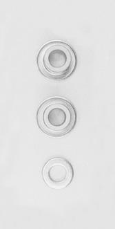
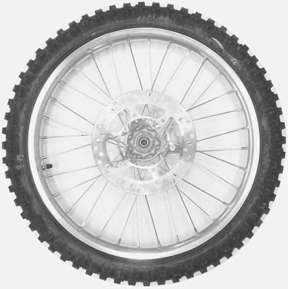

5 B A1 A2 C E D I F1 G J F2 H1 H2 K 4
 The photograph shown indicates the parts dismounted from the motorcycle in addition to the")

6 (FOR DR-Z125) The photograph shown indicates the parts dismounted from the motorcycle in addition to the items shown in the preceding page. A: Throttle assembly Engine stop switch B: Clutch cable (FOR DR-Z125L) The photograph shown indicates the parts dismounted from the motorcycle in addition to the items shown in the preceding page. A: Front brake master cylinder B: Throttle assembly Engine stop switch C: Clutch cable Before assembling the motorcycle, thoroughly understand the Safety Check Out described on page 32. After completion of assembly, carefully check the motorcycle referring to the Safety Check Out, then deliver the motorcycle to the customer. 5


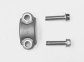
7 ASSEMBLY REMOVING THE BRACKET (FOR DR-Z125L) Remove the bolt to take off the front brake master cylinder from the bracket. Keep the position of front brake master cylinder with its cap facing upwards until it is installed. The bolt is no longer needed and this may be discarded. A: Front brake master cylinder B: Bolt C: Bracket Remove the bracket from the handlebar holder. Be careful not to scratch the fuel tank. The bracket and bolts are no longer needed and these may be discarded. A: Bracket B: Bolt HANDLEBARS Loosen the throttle housing retaining screws. Insert the throttle assembly onto the handlebars. A: Throttle assembly B: Handlebars 6

 FORWARD To install the handlebars correctly, first tighten the bolt A of the front side with specified torque and then tighten the bolt B of the rear side.")

8 Install the handlebars assembly using the two clamps and four bolts. The punch mark on the clamps shows front side. Align the dot mark on the handlebars with the mating surface of the front side of left clamp. A: Clamp B: 8 35 mm flange bolt C: Dot mark D: Punch mark Tighten the handlebar clamp bolts to the specified torque. Handlebar clamp bolt: 23 N m (2.3 kgf-m) FORWARD To install the handlebars correctly, first tighten the bolt A of the front side with specified torque and then tighten the bolt B of the rear side. Make sure that the clamp has no clearance at the front side as shown in the illustration. A: 8 35 mm flange bolt B: 8 35 mm flange bolt C: Dot mark THROTTLE Align the dot mark on the handlebars with mating surface of the throttle housing. Tighten the throttle assembly with two screws after the assembly is positioned so that there is approximately mm of clearance between the grip end and the end of the handlebars. Check to ensure that the throttle operates freely and closes automatically. A: Throttle assembly B: Dot mark C: Screw 7


9 FRONT BRAKE MASTER CYLINDER (FOR DR-Z125L) Install the front brake master cylinder onto the handlebars. Align the dot mark on the handlebars with the master cylinder-to-holder fitting surface. Tighten the front brake master cylinder mounting bolts to the specified torque. Front brake master cylinder mounting bolt: 10 N m (1.0 kgf-m) To install the holder correctly, first tighten the bolt B of the upper side with specified torque and then tighten the bolt C of the lower side. A: Front brake master cylinder B: 6 25 mm flange bolt C: 6 25 mm flange bolt D: Holder E: Dot mark Install the holder in position according to the mark UP. Make sure that the holder has no clearance at the upper side as shown. Check for brake fluid leakage. A: 6 25 mm flange bolt B: Holder C: Front brake master cylinder D: Handlebars Remove the crate axle bracket from the crate base. The bracket and bolt are no longer needed and may be discarded. A: Crate axle bracket B: Bolt 8


 Remove the front axle nut. Remove the front axle from the fork legs.")
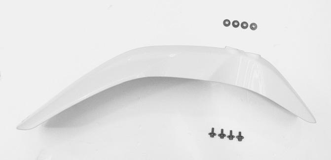
10 1. Lift the front of motorcycle by using a hoist. 2. Raise the rear of motorcycle. 3. Pull the crate base forward, then balance the motorcycle. FRONT FENDER Install the front fender with four sets of mounting parts as shown. A: Front fender B: Collared spacer OD:17.0 mm ID:6.5 mm T:6.5 mm C: 6 16 mm flange bolt (with washer) FRONT Install the front fender to the front fork lower bracket. A: Front fender B: Collared spacer OD:17.0 mm ID:6.5 mm T:6.5 mm C: 6 16 mm flange bolt (with washer) D: Front fork lower bracket FRONT WHEEL (FOR DR-Z125) Remove the front axle nut. Remove the front axle from the fork legs. The vinyl tube is no longer needed and this may be discarded. A: Front axle nut B: Front axle C: Vinyl tube 9


11 Mount the front wheel assembly properly. A: Right fork leg B: Left fork leg C: Axle nut D: Washer OD:20.0 mm ID:10.5 mm E: Front wheel spacer F: Front brake hub panel assembly G: Front axle Clean the brake drum with alcohol or other non-petroleum based solvent. Examine the brake shoes, springs, and operating mechanisms. Install the brake panel into the front wheel hub. A: Front brake hub panel assembly Attach the front wheel spacer to the front wheel hub. When attaching the front wheel spacer, be careful not to damage the oil seal lip. The flange side of the spacer faces the right fork leg. Place the front wheel assembly into the fork legs, aligning the brake hub panel anchor slot onto the stub on the left fork leg. A: Front wheel spacer B: Stub C: Anchor slot D: Oil seal (Lip) 10


 A: Axle nut FRONT WHEEL (FOR DR-Z125L) To prevent brake squeaking and")

12 Insert the front axle from the left side of fork leg and fix the front wheel assembly to the front fork. Never use force to install the front axle. If it cannot be installed by hand, it is not correctly aligned. Place the washer on the right end of the front axle. A: Front axle B: Washer OD:20.0 mm ID:10.5 mm Tighten the front axle nut to the specified torque. Front axle nut: 42 N m (4.2 kgf-m) A: Axle nut FRONT WHEEL (FOR DR-Z125L) To prevent brake squeaking and pad contamination, carefully clean the front brake disc plate with alcohol or other non-petroleum based solvent. This will remove the rust-preventive coating and dirt. Remove the front axle nut. Remove the front axle from the fork legs. The vinyl tube is no longer needed and this may be discarded. A: Front axle nut B: Front axle C: Vinyl tube 11


13 Mount the front wheel assembly properly. A: Right fork leg B: Left fork leg C: Axle nut D: Washer OD:24.0 mm ID:12.5 mm E: Front wheel spacer F: Front axle Remove the supporter from the brake pad of the front brake caliper. Carefully insert the front brake disc plate between the caliper brake pads. A: Supporter B: Disc plate C: Pads RIGHT LEFT Attach the front wheel spacers between the front wheel hub and fork leg. The large flange of the spacer faces the hub. A: Spacer Insert the front axle from the left side of fork leg and fix the front wheel assembly to the front fork. Never use force to install the front axle. If it cannot be installed by hand, it is not correctly aligned. Place the washer on the right end of the front axle. A: Front axle B: Washer OD:24.0 mm ID:12.5 mm 12
 A: Axle nut Place the motorcycle on the side-stand, then remove the hoist hook.")

 The line drawings on page 29, 30 and 31 show the proper routing of")

14 Tighten the front axle nut to the specified torque. Front axle nut: 49 N m (4.9 kgf-m) A: Axle nut Place the motorcycle on the side-stand, then remove the hoist hook. (FOR DR-Z125) The line drawings on page 29 and 31 show the proper routing of the control cables and wirings. Refer to them in addition to following the instructions carefully. A: Clutch cable B: Throttle cable C: Front brake cable D: Engine stop switch wiring harness (FOR DR-Z125L) The line drawings on page 29, 30 and 31 show the proper routing of the control cables, hose and wirings. Refer to them in addition to following the instructions carefully. A: Clutch cable B: Throttle cable C: Front brake hose D: Engine stop switch wiring harness 13


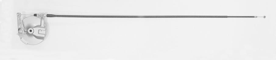
15 FRONT BRAKE CABLE (FOR DR-Z125) Pass the front brake cable to the guide. Pass the front brake cable to the lever cover. A: Front brake cable B: Guide C: Lever cover Check the brake cable end. Align the brake cable end with the recess of brake cam lever as shown. A: Brake cable end B: Brake cam lever Turn the brake cable adjuster and lock nut in as far as possible and align the slots. Insert the inner cable end into the recess in the brake lever, then pull on the outer cable housing and insert it into the adjuster. Do not adjust at this time. Adjustment will be covered in the SERVICING section. Before installing the cable, grease the cable end. Install the lever cover. A: Front brake cable B: Adjuster C: Lock nut D: Cable end E: Lever cover 14


16 FRONT BRAKE CABLE CLIP (FOR DR-Z125) Install the front brake cable clip as shown, leaving the proper amount of slack in the cable between the clip and the brake hub panel. A: Cable clip B: 6 10 mm flange bolt C: Front brake cable INSIDE CLUTCH CABLE Pass the clutch cable to the lever cover. A: Clutch cable B: Lever cover Turn the clutch cable adjuster and lock nut in as far as possible and align the slots. Insert the inner cable end into the recess in the clutch lever, then pull on the outer cable housing and insert it into the adjuster. Do not adjust at this time. Adjustment will be covered in the SERVICING section. Before installing the cable, grease the cable end. Install the lever cover. A: Clutch cable B: Adjuster C: Lock nut D: Cable end E: Lever cover 15


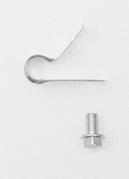
17 ENGINE STOP SWITCH Hook the holders on the grooves of the engine stop switch assembly. Use the holder with an internal thread cutting at the lower side. A: Engine stop switch assembly B: Holder (Upper) C: Holder (Lower) D: Thread cutting Install the engine stop switch to the left of handlebars. A: Engine stop switch assembly B: 3 14 mm screw (with lock washer) CLAMP Clamp the engine stop switch wiring harness with strap. A: Strap L:120 mm B: Engine stop switch wiring harness C: Handlebars FRONT NUMBER PLATE Pass the strap of the number plate around the handlebar bridge pipe. Fit the strap of the number plate into the guide. A: Strap B: Handlebar bridge pipe C: Guide 16


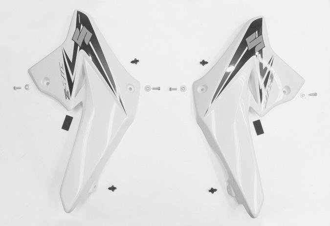
18 FUEL TANK COVER Remove the bolts to take off the seat. A: Seat assembly B: Flange bolt, Stepped washer Stick the rubber cushion to the fuel tank cover (Right and Left) at the mark-off line. Remove the stain from the sticking part and degrease the fuel tank cover. A: Rubber cushion B: Fuel tank cover C: Mark-off line Install the fuel tank cover with flange bolt, stepped washer and fastener. To install the fastener, pull the center pin and fix the fastener by pushing the center pin. A: Fuel tank cover B: 6 16 mm flange bolt C: Stepped washer OD:17.0 mm ID:6.5 mm T:6.5 mm D: Stepped washer OD:16.0 mm ID:6.5 mm T:3.5 mm E: Fastener F: Stay To install the seat, insert the seat hook into the seat hook retainer. Tighten the bolts. A: Seat assembly B: Seat hook C: Seat hook retainer 17


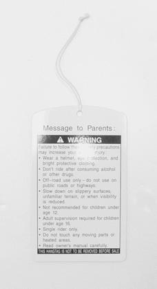
19 FUEL TANK VENT HOSE Install the fuel tank vent hose to the fuel tank cap. Insert the free end of fuel tank vent hose to the hole of front number plate. Be sure not to bend or twist the hose when installing. A: Fuel tank vent hose B: Fuel tank cap C: Front number plate D: Hole FOOTREST Remove the shipping pin from the footrest. Confirm that the right and left footrests move smoothly. A: Footrest B: Shipping pin FUEL LABEL (FOR LIMITED MARKET) Stick the label on the fuel tank cover. A: Fuel tank cover B: Fuel label WARNING TAG Place the warning tag to the handlebar. This hangtag is not to be removed before sale. A: Warning tag 18

 Any air which may have been trapped in the brake fluid circuit must be bled completely.")

20 SERVICING LOWER BRAKE FLUID (FOR DR-Z125L) Keep the motorcycle upright and place the handlebars straight. Check the brake fluid level in the front master cylinder reservoirs. If the fluid level is below the LOWER level indicated in the figure, add the correct type of brake fluid. Refer to the chart below for the proper selection. Specification and Classification DOT 4 Be careful not to spill any brake fluid on the paint or plastic components as they will be damaged. BRAKE AIR BLEEDING (FOR DR-Z125L) Any air which may have been trapped in the brake fluid circuit must be bled completely. If the brake lever feels spongy or weak, then most likely there is air in the hydraulic circuit. To bleed the air from the front brake, use the following procedure: 1. Connect a clear hose to the air bleeder valve and run the hose into a suitable clear container. 2. Pour approximately 1/2 in of brake fluid into the container so that the end of the clear hose is submerged and cannot draw any additional air back into the circuit during the air bleeding servicing. 3. Close the valve, pump and squeeze the lever, and open the valve while squeezing brake lever. 4. Repeat this process until the fluid flowing into the receptacle no longer contains air bubbles. Do not drop brake fluid level below lower level line while bleeding air. 5. After bleeding the brake circuit, tighten the bleeder valve to the specified torque. Reinstall the rubber protective cap. 6. Be sure to check the brake fluid level in the reservoir tank. Brake caliper air bleeder valve: 7.5 N m (0.75 kgf-m) A: Bleeder valve 19


21 FRONT BRAKE (FOR DR-Z125) Check the front brake lever play at the brake lever end when squeezing the lever until pressure is felt. Front brake lever play: mm If adjustment is necessary, carry out the procedure below. 1. Remove the bolt A and front brake cable clip B. 2. Loosen the lock nut F of the brake lever adjuster and turn in the adjuster E as far as possible. 3. Loosen the two lock nuts C of the front brake hub panel. 4. Relocate the adjuster D to obtain the correct play. 5. Firmly tighten the two lock nuts C of the brake panel. Minor adjustments can now be made with the brake lever adjuster E. 6. Tighten the lock nut F and place the lever cover G. 7. Reinstall the front brake cable clip B. This motorcycle is delivered from the factory not tightened the lock nuts C. FRONT BRAKE (FOR DR-Z125L) Remove the lever cover. Check the brake lever play. Front brake lever play: mm If adjustment is necessary, carry out the procedure below: 1. Loosen the lock nut A. 2. Turn the adjuster B in or out until the correct play. 3. Tighten the lock nut A. 4. Fit the lever cover. 20


22 THROTTLE CABLE Check the throttle cable play at the throttle grip. Throttle cable play: mm If adjustment is necessary, carry out the procedure below: 1. Loosen the throttle cable adjuster lock nut A. 2. Turn the adjuster B in or out until the correct play is obtained. 3. Tighten the lock nut A while holding the adjuster B. 4. Place the rubber boot C. After the adjustment is completed, check that handlebar movement does not raise the engine idle speed and that the throttle grip returns smoothly and automatically. CLUTCH CABLE Check the clutch lever play at the clutch lever end when squeezing the lever until pressure is felt. Clutch lever play: mm If adjustment is necessary, carry out the procedure below. 1. Loosen the lock nut A of the clutch lever adjuster and turn in the adjuster B as far as possible. 2. Loosen the cable adjuster lock nut C. 3. Turn the cable adjuster D to obtain the correct play. 4. Tighten the lock nuts C. Minor adjustments can now be made with the clutch lever adjuster B. 5. Place the rubber boot E. 6. Tighten the lock nut A and place the lever cover F. 21

23 DRIVE CHAIN Check the drive chain slack. Drive chain slack: mm If it is too tight or too loose, follow these procedures: 1. Loosen the axle nut. 2. Adjust the slack in the drive chain by turning the right and left chain adjuster nuts. 3. Proper chain slack is obtained when drive chain slack is up and down, at a point midway between the two sprockets. A: Axle nut B: Adjuster nut C: Reference marks 4. After adjusting, tighten the axle nut to the specified torque. 5. Tighten the adjuster nuts securely. Rear axle nut: 54 N m (5.4 kgf-m) mm Make sure that the rear sprocket is properly aligned with the engine sprocket. Verify the reference marks on the swing-arm by sighting down along the chain from the rear end of the motorcycle. Verify that the chain joint clip is installed properly. The opening of the chain joint clip faces away from the direction of travel. A: Direction of travel B: Chain joint clip 22


24 REAR BRAKE PEDAL Check the rear brake pedal height. Rear brake pedal height: 0 10 mm If the rear brake pedal height is not correct, adjust in the following manner: 1. Loosen the lock nut A. 2. Adjust the brake pedal height by turning the brake pedal stopper bolt B to locate the pedal to the correct height below the top face of the footrest C. 3. Tighten the lock nut A. After the brake pedal height has been adjusted, check the brake pedal free travel. Rear brake pedal free travel: mm If adjustment is necessary, adjust the free travel by turning the brake rod adjuster nut D. TIRE PRESSURE Using an accurate air gauge, check the air pressure of the front and rear tires. The pressure should be as shown. COLD INFLATION TIRE PRESSURE FRONT 100 kpa 1.00 kgf/cm 2 14 psi REAR 100 kpa 1.00 kgf/cm 2 14 psi 23

25 ENGINE OIL This motorcycle is shipped from factory with the engine filled with engine oil. Be sure to check oil level. Check the engine oil level through the engine oil inspection window with the motorcycle held vertically on level ground. 1. Start the engine and allow it to run for a few minutes at idling speed. 2. Turn off the engine and wait about three minutes, then check the oil level through the inspection window. 3. If the level is below the L mark, add oil to F level. If the level is above the F mark, drain oil to F level. 4. Reinstall the drain plug and engine oil filler plug. Tighten them securely. Oil drain plug: 28 N m (2.8 kgf-m) A: Engine oil filler plug B: Engine oil level inspection window SAE API JASO 10W-40 SF or SG 10W-40 SH or SJ MA Engine oil Oil quality is a major contributor to your engine s performance and life. Always select good quality engine oil. Use oil with an API (American Petroleum Institute) classification of SF/SG or SH/SJ, or with a JASO classification of MA. API: American Petroleum Institute JASO: Japanese Automobile Standards Organization 24
26 ENGINE OIL VISCOSITY RATING SELECTION CHART 20W W W - 50 ENGINE OIL 10W W - 50 SAE Engine Oil Viscosity Suzuki recommends the use of SAE 10W-40 engine oil. If SAE 10W-40 engine oil is not available, select an alternative according to the left chart. 10W - 30 TEMP. C F JASO T903 The JASO T903 standard is an index to select engine oils for 4-stroke motorcycle and ATV engines. Motorcycle and ATV engines lubricate clutch and transmission gears with engine oil. JASO T903 specifies performance requirements for motorcycle and ATV clutches and transmission. There are two classes, MA and MB. The oil container shows the classification as shown. A: Code number of oil sales company B: Oil classification ENERGY API SERVICE SJ SAE 10W-40 CONSERVING API SERVICE SJ SAE 10W-40 Energy Conserving Suzuki does not recommend the use of ENERGY CONSERVING oils. Some engine oils which have an API classification of SH or higher have an ENERGY CONSERVING indication in the API classification doughnut mark. These oils can affect engine life and clutch performance. Not recommended Recommended 25

27 IDLE SPEED ADJUSTMENT After completing all of the servicing procedures, adjust the engine idle speed by turning the throttle stop screw. The engine idle should be adjusted with engine warmed up. Engine idle speed: r/min A: Throttle stop screw Test ride the motorcycle checking all mechanical functions. Tighten all nuts, bolts, and miscellaneous mounting parts to the proper torque specs. Confirm that all cables and wiring harnesses are connected and routed correctly. 26

 Conventional or 4 marked bolt 7 marked bolt N m kgf-m N m kgf-m 4 1.5 0.15 2.3 0.23 5 3 0.3 4.5 0.45 6 5.5 0.55 10 1.")
28 TIGHTENING TORQUE (FOR DR-Z125) Item Part Name N m kgf-m FRONT FORK A Handlebar clamp bolt B Steering stem head nut C Front fork upper bracket bolt D Front fork lower bracket bolt BRAKE E Front brake cam lever nut F Rear brake cam lever nut Item Part Name N m kgf-m AXLE G Front axle nut H Rear axle nut ABSORBER I Rear shock absorber bolt (Upper) J Rear shock absorber nut (Lower) OTHERS K Rear swingarm pivot nut L Front footrest bolt For other bolts and nuts not listed, refer to this chart. Bolt Diameter (mm) Conventional or 4 marked bolt 7 marked bolt N m kgf-m N m kgf-m Conventional bolt 4 marked bolt 7 marked bolt A C B D F I E J H L K G 27

 50 5.0 OTHERS M Rear swingarm pivot nut 65 6.5 N Front footrest bolt 55 5.5 For other bolts and nuts not listed, refer to this chart.")
29 TIGHTENING TORQUE (FOR DR-Z125L) Item Part Name N m kgf-m FRONT FORK A Handlebar clamp bolt B Steering stem head nut C Front fork upper bracket bolt D Front fork lower bracket bolt BRAKE E Front brake caliper mounting bolt F Front brake master cylinder mounting bolt G Rear brake cam lever nut H Brake caliper air bleeder Item Part Name N m kgf-m AXLE I Front axle nut J Rear axle nut ABSORBER K Rear shock absorber bolt (Upper) L Rear shock absorber nut (Lower) OTHERS M Rear swingarm pivot nut N Front footrest bolt For other bolts and nuts not listed, refer to this chart. Bolt Diameter (mm) Conventional or 4 marked bolt 7 marked bolt N m kgf-m N m kgf-m Conventional bolt 4 marked bolt 7 marked bolt F A C B D E G K H L J N M I 28
30 CABLE ROUTING Front brake cable (FOR DR-Z125) Front brake cable (FOR DR-Z125) Wiring harness Clip Clamp Clutch cable Clutch cable Throttle cable 29
31 FRONT BRAKE HOSE ROUTING (FOR DR-Z125L) Brake hose Guide Brake hose 1 mm Clamp Clamp 30
32 HARNESS ROUTING Throttle cable Clutch cable Front brake cable (FOR DR-Z125) Front brake hose (FOR DR-Z125L) Clamp Engine stop switch lead wire CDI unit UP Engine stop switch lead wire Throttle cable Clamp Clamp Face the clamp end down Clamp Clamp Clutch cable Clamp Generator lead wire 31
33 SAFETY CHECK OUT After completion of the setting-up the motorcycle all the following items should be doublechecked to confirm that the operation and function of the motorcycle are satisfactory. Now, setting-up the motorcycle and pre-delivery inspection have been completed and the motorcycle can be passed to the customer. ENGINE AND TRANSMISSION ITEM MEASURE SPECIFICATIONS Engine oil Check/Refill 850 ml Fuel tank Drain/Fill 4.8 L Throttle cable Check/Adjust mm Idle r/min Check/Adjust r/min Exhaust system Leakage Fuel system connection Leakage/Circlip CHASSIS ITEM MEASURE SPECIFICATIONS Disc brake (FOR DR-Z125L) Clean/Fluid level Front brake lever (FOR DR-Z125L) Check/Adjust mm Front brake lever (FOR DR-Z125) Check/Adjust mm Rear brake pedal Check/Adjust Height: 0 10 mm Play: mm Clutch cable Check/Adjust mm Drive chain Check/Adjust/ Lubricate mm Front fork Check Rear shock absorber Check Oiling points All necessary points Wiring and cable Routing/Operation Wiring connectors Clean/Tight Tighten all nuts and bolts Cotter pins, circlip and fasteners Torque those listed in this manual Check COLD TIRE INFLATION PRESSURE FRONT 100 kpa 1.0 kgf/cm 2 14 psi ITEM Switch Operations Engine stop switch Engine Transmission Drive chain Clutch Brake Steering Suspension Control cables Leakage ELECTRICALS REAR 100 kpa 1.0 kgf/cm 2 14 psi CHECK FOR Operation ROAD TEST INSPECTION ITEM CHECK FOR Starting/Acceleration/ Smoothness/Noise Operation/Noise Operation/Noise Operation/Noise Operation/Noise Stability Operation Operation/Proper return Fuel/Oil/Exhaust 32
DIFFERENCE BETWEEN LT-Z400K3 AND LT-Z400K8
 PAGE: 1 OF 11 SUBJECT: NOTICE OF SET-UP MANUAL APPLICABLE MODEL: LT-Z400K8 EFFECTIVE ENGINE OR FRAME NO.: REFERENCE: This bulletin is to inform you of set-up procedures of LT-Z400K8. Please inform your
CHASSIS CONTENTS EXTERIOR PARTS 6-1 FRAME COVER 6-2 REAR FRAME COVER 6-4 FRONT WHEEL 6-6 FRONT BRAKE 6-10 HANDLEBARS 6-17 FRONT FORK 6-19
 CHASSIS CONTENTS EXTERIOR PARTS 6- FRAME COVER 6- REAR FRAME COVER 6-4 FRONT WHEEL 6-6 FRONT BRAKE 6-0 HANDLEBARS 6-7 FRONT FORK 6-9 STEERING 6-6 REAR WHEEL 6-3 REAR BRAKE 6-39 6 REAR SHOCK ABSORBER 6-43
DIFFERENCE BETWEEN LT-Z50K6 AND LT-Z50K8
 PAGE: 1 OF 5 SUBJECT: NOTCE OF SET-UP MANUAL APPLCABLE MOEL: LT-Z50K8 EFFECTVE ENGNE OR FRAME NO.: REFERENCE: This bulletin is to inform you of set-up procedures of LT-Z50K8. Please inform your dealers
FOREWORD. Indicates a potential hazard that could result in death or injury. Indicates a potential hazard that could result in vehicle damage.
 FOREWORD This vehicle has been designed and produced utilizing Suzuki s most modern technology. The finest product, however, cannot perform properly unless it is correctly assembled and serviced. This
Unit: mm (in) ITEM STANDARD LIMIT IN. 33 (1.3) EX.
 ITEM STANDARD LIMIT IN. 33 (1.3) EX.") Model: DR650SEL0 E-03, 24, 28, 33 Date: July 16, 2009 SERVICE DATA VALVE + GUIDE Valve diam. Valve clearance (when engine is cold) Valve guide to valve stem clearance Valve stem deflection Valve guide
Model: DR650SEL0 E-03, 24, 28, 33 Date: July 16, 2009 SERVICE DATA VALVE + GUIDE Valve diam. Valve clearance (when engine is cold) Valve guide to valve stem clearance Valve stem deflection Valve guide
CHASSIS CONTENTS EXTERIOR PARTS 6-1 FRONT WHEEL 6-2 FRONT BRAKE 6-6 HANDLEBARS 6-12 REAR WHEEL 6-30 REAR BRAKE 6-34 REAR SHOCK ABSORBER 6-36
 CHASSIS CONTENTS EXTERIOR PARTS 6-1 FRONT WHEEL 6-2 FRONT BRAKE 6-6 HANDLEBARS 6-12 FRONT FORK ( ) 6-14 FRONT FORK ( ) 6-20 STEERING 6-27 REAR WHEEL 6-30 REAR BRAKE 6-34 REAR SHOCK ABSORBER 6-36 6 SWING
12. FRONT WHEEL/FRONT BRAKE/
 12 12 12-0 SERVICE INFORMATION... 12-1 FRONT BRAKE... 12-7 TROUBLESHOOTING... 12-2 FRONT SHOCK ABSORBER... 12-18 STEERING HANDLEBAR... 12-3 FRONT FORK... 12-21 FRONT WHEEL... 12-4 SERVICE INFORMATION GENERAL
CHASSIS CONTENTS EXTERIOR PARTS 7-1 FRONT WHEEL 7-2 FRONT BRAKE 7-6 HANDLEBARS 7-13 FRONT FORK 7-15 STEERING 7-23 REAR WHEEL 7-26 REAR BRAKE 7-30
 CHASSIS CONTENTS EXTERIOR PARTS 7- FRONT WHEEL 7-2 FRONT BRAKE 7-6 HANDLEBARS 7-3 FRONT FORK 7-5 STEERING 7-23 REAR WHEEL 7-26 REAR BRAKE 7-30 REAR SHOCK ABSORBER 7-32 SWING ARM 7-33 7 7- CHASSIS EXTERIOR
12. FRONT WHEEL/FRONT BRAKE/
 12 4.5kgm 0.9kg-m 4.5kg-m 12-0 SERVICE INFORMATION... 12-1 HYDRAULIC BRAKE... 12-10 TROUBLESHOOTING... 12-2 FRONT SHOCK ABSORBER... 12-16 FRONT WHEEL... 12-3 STEERING HANDLEBAR... 12-19 FRONT BRAKE...
CHASSIS CONTENTS FRONT WHEEL 6-1 FRONT BRAKE 6-6 FRONT FORK 6-14 STEERING STEM 6-20 REAR WHEEL AND REAR BRAKE 6-25 SUSPENSION 6-31 REAR SWING ARM 6-36
 CHASSIS CONTENTS FRONT WHEEL 6-1 FRONT BRAKE 6-6 FRONT FORK 6-14 STEERING STEM 6-20 REAR WHEEL AND REAR BRAKE 6-25 SUSPENSION 6-31 REAR SWING ARM 6-36 6 6-1 CHASSIS FRONT WHEEL REMOVAL Support the machine
FRONT WHEEL AND BRAKE DISCS. Order Job/Part Q ty Remarks Removing the front wheel and brake discs NOTE:
 FRONT WHEEL AND BRAKE DISCS EAS00514 SIS FRONT WHEEL AND BRAKE DISCS 1 2 3 4 Order Job/Part Q ty Remarks Removing the front wheel and brake discs Remove the parts in the order listed. Place the motorcycle
MASTER CYLINDER INSPECTION
 7-16 CHASSIS A-PDF Split DEMO : Purchase from www.a-pdf.com to remove the watermark Remove the piston assembly. MASTER CYLINDER INSPECTION MASTER CYLINDER Inspect the master cylinder bore for any scratches
I: INSPECT AND CLEAN, ADJUST, LUBRICATE OR REPLACE IF NECESSARY C: CLEAN A: ADJUST R: REPLACE L: LUBRICATE I: INSPECTION D: DIAGNOSE
 2. Periodic Maintenance > Periodic Maintenance Chart XCITING 400i Maintenance Schedule Perform the pre-ride inspection (Owner's Manual) at each scheduled maintenance period. This interval should be judged
Valve + Valve Guide Unit: mm (in) Item Standard Limit Valve diam. IN (1.20) EX (1.06) Valve clearance (when cold)
 Item Standard Limit Valve diam. IN (1.20) EX (1.06) Valve clearance (when cold)") Model: LT-A400FL9 P-17, 24, 28,03 Date: Feb. 12, 2018 SERVICE DATA Valve + Valve Guide Valve diam. IN. 30.6 (1.20) EX. 27.0 (1.06) Valve clearance (when cold) IN. 0.05 0.10 (0.002 0.004) EX. 0.22 0.27
Model: LT-A400FL9 P-17, 24, 28,03 Date: Feb. 12, 2018 SERVICE DATA Valve + Valve Guide Valve diam. IN. 30.6 (1.20) EX. 27.0 (1.06) Valve clearance (when cold) IN. 0.05 0.10 (0.002 0.004) EX. 0.22 0.27
CHASSIS CONTENTS FRONT WHEEL 6-1 FRONT BRAKE 6-7 FRONT FORK 6-14 STEERING 6-18 REAR WHEEL AND REAR BRAKE 6-22
 CHASSIS CONTENTS FRONT WHEEL 6- FRONT BRAKE 6-7 FRONT FORK 6-4 STEERING 6-8 REAR WHEEL AND REAR BRAKE 6-6 6- CHASSIS FRONT WHEEL REMOVAL AND DISASSEMBLY Remove the front brake caliper by removing the mounting
TIGHTENING TORQUE CHART For other nuts and bolts not listed in the preceding page, refer to this chart:
 TIGHTENING TORQUE ENGINE ITEM N m kgfm lbft Cylinder head cover bolt 14 1.4 10.0 Spark plug 11 1.1 8.0 Cylinder head bolt (M10) 47 4.7 18.0 (M6) 10 1.0 7.0 Cylinder bolt 10 1.0 7.0 Camshaft journal holder
VULCAN 900 Custom. VN900 Custom. Motorcycle Assembly & Preparation Manual
 VULCAN 900 Custom VN900 Custom Motorcycle Assembly & Preparation Manual Foreword In order to ship Kawasaki vehicles as efficiently as possible, they are partially disassembled before crating. Since some
BRAKE SYSTEM Return To Main Table of Contents
 BRAKE SYSTEM Return To Main Table of Contents GENERAL... 2 BRAKE PEDAL... 10 MASTER CYLINDER... 13 BRAKE BOOSTER... 16 BRAKE LINE... 18 PROPORTIONING VALVE... 19 FRONT DISC BRAKE... 20 REAR DRUM BRAKE...
10. ALTERNATOR/STARTER CLUTCH
 10. ALTERNATOR/STARTER CLUTCH SYSTEM COMPONENTS 10-2 SERVICE INFORMATION 10-3 TROUBLESHOOTING 10-3 LEFT CRANKCASE COVER REMOVAL 10-4 STATOR/IGNITION PULSE GENERATOR 10-5 FLYWHEEL/STARTER CLUTCH 10-6 LEFT
Motorcycle Assembly & Preparation Manual
 VULCAN 900 CLASSIC VN900 CLASSIC VULCAN 900 CLASSIC LT Motorcycle Assembly & Preparation Manual Foreword In order to ship Kawasaki vehicles as efficiently as possible, they are partially disassembled
SERVICE INFORMATION 11-1 FRONT WHEEL/SUSPENSION/ STEERING XL FRONT WHEEL 11 7 FORK STEERING STEM 11 18
 XL200 11. FRONT WHEEL/SUSPENSION/ STEERING SERVICE INFORMATION 11 1 TROUBLESHOOTING 11 2 HANDLEBAR 11 3 FRONT WHEEL 11 7 FORK 11 11 STEERING STEM 11 18 SERVICE INFORMATION GENERAL A contaminated brake
19. HYDRAULIC BRAKE 19-1 SYSTEM COMPONENTS FRONT MASTER CYLINDER SERVICE INFORMATION 19-3 FRONT BRAKE CALIPER 19-15
 19. HYDRAULIC BRAKE SYSTEM COMPONENTS- 19-2 FRONT MASTER CYLINDER 19-10 SERVICE INFORMATION 19-3 FRONT BRAKE CALIPER 19-15 TROUBLESHOOTING 19-4 REAR MASTER CYLINDER 19-18 BRAKE FLUID REPLACEMENT/ REAR
Ninja ZX -10R Ninja ZX -10R ABS
 Ninja ZX -10R Ninja ZX -10R ABS Recharge the Battery First! This motorcycle comes with a pre-filled, pre-charged sealed battery, eliminating the need for dealers to prepare the battery by filling it with
18. REAR WHEEL/SUSPENSION
 18. REAR WHEEL/SUSPENSION SYSTEM COMPONENTS 182 REAR AXLE/BEARING HOLDER 187 SERVICE INFORMATION 183 REAR SHOCK ABSORBER 1816 TROUBLESHOOTING 186 SHOCK LINKAGE 1818 REAR WHEEL 187 SWINGARM 1820 181 SYSTEM
INSTALLATION INSTRUCTIONS
 INSTALLATION INSTRUCTIONS DISC BRAKE CONVERSION KITS A121-1, A121-2, A121-3, A121-4 1967-69 Ford & Mercury Thank you for choosing STAINLESS STEEL BRAKES CORPORATION for your braking needs. Pleases take
INSTALLATION INSTRUCTIONS
 INSTALLATION INSTRUCTIONS FRONT DISC BRAKE CONVERSION KITS A148-9 & A148-15 1949-54 Chevy Trucks Thank you for choosing STAINLESS STEEL BRAKES CORPORATION for your braking needs. Please take the time to
SERVICE DATA ITEM STD/SPEC. LIMIT. ( in) 1st & 2nd R Approx. 8.2 mm (0.32 in)
 1st & 2nd R Approx. 8.2 mm (0.32 in)") 2 STROKE CYLINDER + PISTON + PISTON RING CONROD + CRANKSHAFT CLUTCH SERVICE DATA Piston to cylinder clearance 0.045 0.055 mm (0.0018 0.0022 in) 0.120 mm (0.0047 in) Cylinder bore Piston diam. Cylinder
2 STROKE CYLINDER + PISTON + PISTON RING CONROD + CRANKSHAFT CLUTCH SERVICE DATA Piston to cylinder clearance 0.045 0.055 mm (0.0018 0.0022 in) 0.120 mm (0.0047 in) Cylinder bore Piston diam. Cylinder
INSTALLATION INSTRUCTIONS
 INSTALLATION INSTRUCTIONS PERFORMANCE AT THE WHEELS KITS W156-6 & W156-7 1965-74 MOPAR B & E BODY Thank you for choosing STAINLESS STEEL BRAKES CORPORATION for your braking needs. Pleases take the time
Brake System H TX, H2.0TXS [B475]; H TX [B466] Safety Precautions Maintenance and Repair
![Brake System H TX, H2.0TXS [B475]; H TX [B466] Safety Precautions Maintenance and Repair](/thumbs/86/93834005.jpg "Brake System H TX, H2.0TXS [B475]; H TX [B466] Safety Precautions Maintenance and Repair") HMM180001 Brake System H1.5-1.8TX, H2.0TXS [B475]; H2.5-3.5TX [B466] Safety Precautions Maintenance and Repair When lifting parts or assemblies, make sure all slings, chains, or cables are correctly fastened,
HMM180001 Brake System H1.5-1.8TX, H2.0TXS [B475]; H2.5-3.5TX [B466] Safety Precautions Maintenance and Repair When lifting parts or assemblies, make sure all slings, chains, or cables are correctly fastened,
INSTALLATION INSTRUCTIONS
 INSTALLATION INSTRUCTIONS REAR DISC BRAKE CONVERSION KIT A158 1994-97 Dodge Ram 1500 (2WD & 4WD) and REAR DISC BRAKE CONVERSION KIT A158-1 1998-01 Dodge Ram 1500 (2WD & 4WD) Thank you for choosing STAINLESS
M-2300-T 6-Piston Mustang Brake Kit INSTALLATION INSTRUCTIONS
 Please visit www.fordracingparts.com for the most current instruction information!!! PLEASE READ ALL OF THE FOLLOWING INSTRUCTIONS CAREFULLY PRIOR TO INSTALLATION. AT ANY TIME YOU DO NOT UNDERSTAND THE
INSTALLATION INSTRUCTIONS
 INSTALLATION INSTRUCTIONS DISC BRAKE CONVERSION KIT A120-20, A120-21 1964 1 /2-66 Ford & Mercury Thank you for choosing STAINLESS STEEL BRAKES CORPORATION for your braking needs. Pleases take the time
GSX-R1000 K7/K8 Front master cylinder replacement procedure
 GSX-R000 K7/K8 Front master cylinder replacement procedure.preparation Replacement parts Part name P/NO Q ty Description Cylinder kit, FR MASTER 59000-080-RX0 Master cylinder set (5960-7H0) Bracket, reservoir
INSTALLATION INSTRUCTIONS
 INSTALLATION INSTRUCTIONS COMP. R AND COMP. S QUICK CHANGE KITS A200, A200-1 Thank you for choosing STAINLESS STEEL BRAKES CORPORATION for your braking needs. Pleases take the time to read and carefully
INSTALLATION INSTRUCTIONS
 INSTALLATION INSTRUCTIONS POWER FRONT DISC CONVERSION KIT A126-7 1963-66 CHEVY C10 PICKUP NON-POWER FRONT DISC CONVERSION KIT A126-8 1963-72 CHEVY C10 PICKUP Thank you for choosing STAINLESS STEEL BRAKES
INSTALLATION INSTRUCTIONS
 INSTALLATION INSTRUCTIONS PERFORMANCE AT THE WHEELS KIT W155-5 CHRYSLER 8 3 /4" & 9 3 /4" REAR AXLES Thank you for choosing STAINLESS STEEL BRAKES CORPORATION for your braking needs. Please take the time
INSTALLATION INSTRUCTIONS
 INSTALLATION INSTRUCTIONS REAR DISC BRAKE CONVERSION KIT A125-2 1955-70 FULL SIZE CHEVROLET Thank you for choosing STAINLESS STEEL BRAKES CORPORATION for your braking needs. Pleases take the time to read
INSTALLATION INSTRUCTIONS
 INSTALLATION INSTRUCTIONS REAR DISC CONVERSION KIT A128-4 1997-2004 JEEP WRANGLER (TJ) WITH DANA 44 AXLES (non-abs) Thank you for choosing STAINLESS STEEL BRAKES for your braking needs. Pleases take the
INSTALLATION INSTRUCTIONS
 INSTALLATION INSTRUCTIONS FRONT DISC BRAKE CONVERSION KITS: A132-1, A133, A133-1 A134, A134-1 1968-73 MUSTANG/FORD Thank you for choosing STAINLESS STEEL BRAKES CORPORATION for your braking needs. Please
PERIODIC MAINTENANCE
 PERIODIC MAINTENANCE CONTENTS PERIODIC MAINTENANCE SCHEDULE 2 1 MAINTENANCE PROCEDURES 2 3 2 BATTERY 2 3 CYLINDER HEAD NUTS AND EXHAUST PIPE NUTS 2 4 CYLINDER HEAD AND CYLINDER 2 4 SPARK PLUG 2 4 FUEL
Caution: Refer to Adding Fluid to the Brake System Caution in the Preface section.
 Page 1 of 6 2009 Pontiac G8 G8 Service Manual Brakes Disc Brakes Repair Instructions Document ID: 2094891 Rear Disc Brake Pads Replacement Special Tools J 23738-A Hand Vacuum Pump. Removal Procedure Warning:
INSTALLATION INSTRUCTIONS
 INSTALLATION INSTRUCTIONS PERFORMANCE AT THE WHEELS KIT W125-42 GM 10 & 12 Bolt Rear Axles with Staggered or non-staggered Shocks with C-Clips Thank you for choosing STAINLESS STEEL BRAKES CORPORATION
Parking brake Mechanical brake acting on rear wheels
 11 Brake System 11.1 General SPECIFICATIONS EJTC0010 Master cylinder Type Tandem type I.D. mm(in.) 20.64 mm (0.813 in.) Fluid level warning sensor Provided Brake booster Type Vacuum Boosting ratio 4.0
P/N Instr Rev Page 1 of 11
 BRAKE AND CLUTCH KIT P/N 2883864 IMPORTANT Due to the technical nature of this kit, Indian Motorcycle insists this installation be performed by a certified Indian Motorcycle Technician. APPLICATION Verify
1999 Toyota RAV BRAKES Disc & Drum - Trucks & Vans
 DESCRIPTION & OPERATION 1999-2000 BRAKES Disc & Drum - Trucks & Vans WARNING: For warnings and procedures regarding vehicles equipped with Anti-Lock Brake Systems (ABS), see appropriate ANTI-LOCK article.
X4 (GREEN) (A2000ATF2AUSG) Page 1 of 80 AIR INTAKE ASSEMBLY
 (A2000ATF2AUSG) Page 1 of 80 AIR INTAKE ASSEMBLY") 2000 300 2X4 (GREEN) (A2000ATF2AUSG) Page 1 of 80 AIR INTAKE ASSEMBLY 2000 300 2X4 (GREEN) (A2000ATF2AUSG) Page 2 of 80 AIR INTAKE ASSEMBLY Ref # Part Number Qty S/P/F Description 1 3570-001 1 /P Intake,
2000 300 2X4 (GREEN) (A2000ATF2AUSG) Page 1 of 80 AIR INTAKE ASSEMBLY 2000 300 2X4 (GREEN) (A2000ATF2AUSG) Page 2 of 80 AIR INTAKE ASSEMBLY Ref # Part Number Qty S/P/F Description 1 3570-001 1 /P Intake,
B B B
 FIG CYLINDER Suzuki Worldwide Motorcycle-ATV Page: of -0B00-00 0-00 0-000 0-00 0-0B0-0B0 0-0 0-0 Head, Cylinder Gasket, Cylinder Head Spark Plug (ngk,bphs) Spark Plug (nd,wfp-u) Cylinder Gasket, Cylinder
ATV 2012 Model: LT-F250L2 Date: February 2011
 LT-F250L2 ATV 2012 Model: LT-F250L2 Date: February 2011 MSRP $4,499 Flame Red (YT9) Key Features 1. 246cm3, 1-cylinder, SOHC engine is designed to produce abundant midrange torque. 2. Mid-range power is
BRAKE SYSTEM Nissan 240SX DESCRIPTION BRAKE BLEEDING * PLEASE READ FIRST * BLEEDING PROCEDURES ADJUSTMENTS BRAKE PEDAL HEIGHT SPECS TABLE
 BRAKE SYSTEM 1990 Nissan 240SX 1990 BRAKE SYSTEMS Nissan Disc & Drum Axxess, Maxima, Pathfinder, Pickup, Pulsar NX, Sentra, Stanza, 240SX, 300ZX DESCRIPTION All brake systems are hydraulically operated
This chapter covers the location and servicing of the front brake components for the KYMCO MXU 700i and MXU 500i models.
 KYMCO MXU 500i/700i Repair Manual Brake System 9.Brake System This chapter covers the location and servicing of the front brake components for the KYMCO MXU 700i and MXU 500i models. 1.Brake Discs... 9-3
CHAS FRONT FORK FRONT FORK LEGS 4-45 FRONT FORK. Order Job/Part Q ty Remarks
 EAS00647 FRONT FORK FRONT FORK LEGS 30 Nm (3.0 m kg, 22 ft lb) 6 Nm (0.6 m kg, 4.3 ft lb) 30 Nm (3.0 m kg, 22 ft lb) Order Job/Part Q ty Remarks 2 3 4 5 Removing the front fork legs Front wheel Front brake
3. INSPECTION/ADJUSTMENT
 3 3 INSPECTION/ADJUSTMENT SERVICE INFORMATION -------------------------------------------- 3-1 MAINTENANCE SCHEDULE ---------------------------------------- 3-2 FUEL LINE/FUEL FILTER -------------------------------------------
INSTALLATION INSTRUCTIONS
 INSTALLATION INSTRUCTIONS REAR DISC BRAKE CONVERSION KIT A125-3 1965-72 GM A-BODY 10 & 12 BOLT AXLES Thank you for choosing STAINLESS STEEL BRAKES CORPORATION for your braking needs. Pleases take the time
INSTALLATION INSTRUCTIONS
 INSTALLATION INSTRUCTIONS PERFORMANCE AT THE WHEELS KIT W120-22, W120-23 1964 1/2-69 MUSTANG Thank you for choosing STAINLESS STEEL BRAKES CORPORATION for your braking needs. Pleases take the time to read
ATV 90 UTILITY GREEN (A2006KUB2BUSG) Page 1 of 60 AIR INTAKE ASSEMBLY
 Page 1 of 60 AIR INTAKE ASSEMBLY") 2006 ATV 90 UTILITY GREEN (A2006KUB2BUSG) Page 1 of 60 AIR INTAKE ASSEMBLY 2006 ATV 90 UTILITY GREEN (A2006KUB2BUSG) Page 2 of 60 AIR INTAKE ASSEMBLY Ref # Part Number Qty S/P/F Description 1 3303-005
2006 ATV 90 UTILITY GREEN (A2006KUB2BUSG) Page 1 of 60 AIR INTAKE ASSEMBLY 2006 ATV 90 UTILITY GREEN (A2006KUB2BUSG) Page 2 of 60 AIR INTAKE ASSEMBLY Ref # Part Number Qty S/P/F Description 1 3303-005
INSTALLATION INSTRUCTIONS
 INSTALLATION INSTRUCTIONS FX4 ELITE REAR DISC CONVERSION KITS WITH INTERNAL PARKING BRAKE A110-14, A111-25, A111-29 for FORD 8" & 9" REAR ENDS Thank you for choosing STAINLESS STEEL BRAKES CORPORATION
INSTALLATION INSTRUCTIONS
 INSTALLATION INSTRUCTIONS REAR DISC BRAKE CONVERSION KITS A112, A112-1 & A112-93 1979-93 FORD MUSTANG with 7.5" & 8.8" AXLES Thank you for choosing STAINLESS STEEL BRAKES CORPORATION for your braking needs.
Motorcycle 2012 Model: RM-Z450 Date: August 2011
 RM-Z450L2 Motorcycle 2012 Model: RM-Z450 Date: August 2011 New Feature New graphics Key Features 1. 449cm3 4-stroke liquid-cooled DOHC 4-valve fuel-injected engine developed and refined to deliver phenomenal
90 Utility Model Number A2013KUB2BUSZ SHARE OUR PASSION.
 2013 90 Utility Model Number A2013KUB2BUSZ TM SHARE OUR PASSION. TABLE OF CONTENTS 2013 ATV 90 (Model No. A2013KUB2BUSZ) BODY PANEL AND HEADLIGHT ASSEMBLY... 1 FRONT AND REAR RACK ASSEMBLY... 2 FRAME AND
INSTALLATION INSTRUCTIONS
 INSTALLATION INSTRUCTIONS DISC BRAKE CONVERSION KITS A120-4 & A120-5 1964-1/2-66 Ford & Mercury Thank you for choosing STAINLESS STEEL BRAKES CORPORATION for your braking needs. Pleases take the time to
Motorcycle 2012 Model: LS650L2 Date: May 2011
 LS650L2 Motorcycle 2012 Model: LS650L2 Date: May 2011 MSRP $5,399 Metallic Fox Orange / Glass Sparkle Black (JGS) Key Features 1. 652cm3 (39.8 cu. in), 4-stroke, air-cooled, SOHC engine with Twin Swirl
~ HONDA CB1000C IIOIL PUMP. rw_u LUBRICATION ENGINE LUBRICATION DIAGRAM. Date of Issue: Sept., 1982 HONDA MOTOR CO., ltd.
 LUBRICATION ENGINE LUBRICATION DIAGRAM EXHAUST CAMSHAFT ~ HONDA CB1000C INTAKE CAMSHAFT,t Oil FilTER Oil COOLER PRIMARY CHAIN TENSIONER IIOIL PUMP PRIMARY SHAFT TRANSMISSION MAINSHAFT 01 COUNTERSHAFT Oil
INSPECTION/ADJUSTMENT
 3 3 INSPECTION/ADJUSTMENT SERVICE INFORMATION----------------------------------------------------------------------- 3-1 MAINTENANCE SCHEDULE-------------------------------------------------------------------
WARNING. Indicates a hazardous situation which, if not avoided, could result in death or serious injury. WARNING
 Floating QRS Short Shaft Conversion (Kit P/N 860 200 832) The following symbols may be used in this document: WARNING Indicates a hazardous situation which, if not avoided, could result in death or serious
SERVICE DATA. Unit: mm (in) ITEM STD/SPEC. LIMIT Valve diam. 29 IN. (1.14) EX IN. ( ) EX.
 ITEM STD/SPEC. LIMIT Valve diam. 29 IN. (1.14) EX IN. ( ) EX.") 4 STROKE VALVE + GUIDE SERVICE DATA Date: November 23, 2000 Valve diam. 29 (1.14) 24 (0.94) Valve clearance (when cold) 0.10 0.20 (0.004 0.008) 0.20 0.30 (0.008 0.012) Valve guide to valve stem 0.010 0.037
4 STROKE VALVE + GUIDE SERVICE DATA Date: November 23, 2000 Valve diam. 29 (1.14) 24 (0.94) Valve clearance (when cold) 0.10 0.20 (0.004 0.008) 0.20 0.30 (0.008 0.012) Valve guide to valve stem 0.010 0.037
BRAKE SYSTEM Article Text 1996 Toyota RAV4 For Copyright 1998 Mitchell Repair Information Company, LLC Wednesday, September 13, :30PM
 Article Text ARTICLE BEGINNING 1996 BRAKES Toyota - Disc & Drum RAV4 * PLEASE READ THIS FIRST * WARNING: For warnings and procedures regarding vehicles equipped with Anti-Lock Brake Systems (ABS), see
Brake Upgrade Kit Fitting Instructions Bonneville America
 WARNING: Always have Triumph approved parts, accessories and conversions fitted by a trained technician of an authorised Triumph Dealer. The fitment of parts, accessories and conversions by a technician
INSTALLATION INSTRUCTIONS
 INSTALLATION INSTRUCTIONS REAR DISC BRAKE CONVERSION KITS SUM-BK1329-X, SUM-BK1329-99904, SUM-BK1330-X, SUM-BK1330-99904 CHRYSLER 8 3 /4", 9 3 /4" and 2-PIECE REAR AXLES Thank you for choosing SUMMIT RACING
18_25~~ VI ~.' ""'~. ~~ ft lb), f? 8-13 N m qj ~O..f9 ( kg-m. .0 ~J. I i~" C;Q () 0 ~,t) ~ ft lb), ~, ' ~.
, f? 8-13 N m qj ~O..f9 ( kg-m. .0 ~J. I i~ C;Q () 0 ~,t) ~ ft lb), ~, ' ~.") ~El:OlV:D.A. FRONT: 25-35 N m (2.5-3.5 kg-m, 18_25~~ REAR: 30-40 N m (3.0-4,0 kg-m VI ~.' ""'~. ~~ 22-29 ft lb), f? 8-13 N m qj ~O..f9 (0.8-1.3kg-m C;Q () 0 ~,t) ~ 1------ 6-9 ft lb),.0 ~J. I i~" ~, '
~El:OlV:D.A. FRONT: 25-35 N m (2.5-3.5 kg-m, 18_25~~ REAR: 30-40 N m (3.0-4,0 kg-m VI ~.' ""'~. ~~ 22-29 ft lb), f? 8-13 N m qj ~O..f9 (0.8-1.3kg-m C;Q () 0 ~,t) ~ 1------ 6-9 ft lb),.0 ~J. I i~" ~, '
2.Periodic Maintenance
 KYMCO MXU 500i/700i Repair Manual Periodic Maintenance 2.Periodic Maintenance This chapter covers the location and servicing of the periodic maintenance items for the KYMCO MXU 700i and MXU 500i models.
20 C (68 F) Ω C (68 86 F)
 Ω C (68 86 F)") Page 1 of 10 Service Data 0C Emission Control Devices EVAP system purge control solenoid valve power supply (If equipped) EVAP system purge control solenoid valve resistance (If equipped) PAIR control
Page 1 of 10 Service Data 0C Emission Control Devices EVAP system purge control solenoid valve power supply (If equipped) EVAP system purge control solenoid valve resistance (If equipped) PAIR control
ATV 90 UTILITY CALIFORNIA GREEN (A2008KUB2BCAG) Page 1 of 58 AIR INTAKE ASSEMBLY
 Page 1 of 58 AIR INTAKE ASSEMBLY") 2008 ATV 90 UTILITY CALIFORNIA GREEN (A2008KUB2BCAG) Page 1 of 58 AIR INTAKE ASSEMBLY 2008 ATV 90 UTILITY CALIFORNIA GREEN (A2008KUB2BCAG) Page 2 of 58 AIR INTAKE ASSEMBLY Ref # Part Number Qty S/P/F Description
2008 ATV 90 UTILITY CALIFORNIA GREEN (A2008KUB2BCAG) Page 1 of 58 AIR INTAKE ASSEMBLY 2008 ATV 90 UTILITY CALIFORNIA GREEN (A2008KUB2BCAG) Page 2 of 58 AIR INTAKE ASSEMBLY Ref # Part Number Qty S/P/F Description
ATV 300 DVX CAT GREEN (A2011KSF2BUSZ) Page 1 of 56 AIR INTAKE ASSEMBLY
 Page 1 of 56 AIR INTAKE ASSEMBLY") 2011 ATV 300 DVX CAT GREEN (A2011KSF2BUSZ) Page 1 of 56 AIR INTAKE ASSEMBLY 2011 ATV 300 DVX CAT GREEN (A2011KSF2BUSZ) Page 2 of 56 AIR INTAKE ASSEMBLY Ref # Part Number Qty S/P/F Description 1 3303-705
2011 ATV 300 DVX CAT GREEN (A2011KSF2BUSZ) Page 1 of 56 AIR INTAKE ASSEMBLY 2011 ATV 300 DVX CAT GREEN (A2011KSF2BUSZ) Page 2 of 56 AIR INTAKE ASSEMBLY Ref # Part Number Qty S/P/F Description 1 3303-705
ATV 2012 Model: LT-Z400/Z Date: February 2011
 LT-Z400/ZL2 ATV 2012 Model: LT-Z400/Z Date: February 2011 MSRP $7,099 White (30H) Key Features 1. 398 cm3, 1-cylinder, liquid-cooled, DOHC, aluminum-alloy engine with a flat torque curve and strong response
INSTALLATION INSTRUCTIONS
 INSTALLATION INSTRUCTIONS FRONT BIG BRAKE CONVERSION KIT A112-5 1987-93 FORD MUSTANG Thank you for choosing STAINLESS STEEL BRAKES CORPORATION for your braking needs. Pleases take the time to read and
ATV I l. l u. r a. Parts Manual ARCTIC CAT. 250 cc/300 cc
 2000 I l l u st ATV 250 cc/300 cc Model No. A2000ATE2AUSG (250 - Green) Model No. A2000ATE2AUSR (250 - Red) Model No. A2000ATF2AUSG (300 2x4 - Green) Model No. A2000ATF2AUSR (300 2x4 - Red) Model No. A2000ATF4AUSG
ATV 50 DVX BLACK-RED (A2008KSA2BUSD) Page 1 of 60 AIR INTAKE ASSEMBLY
 Page 1 of 60 AIR INTAKE ASSEMBLY") 2008 ATV 50 DVX BLACK-RED (A2008KSA2BUSD) Page 1 of 60 AIR INTAKE ASSEMBLY 2008 ATV 50 DVX BLACK-RED (A2008KSA2BUSD) Page 2 of 60 AIR INTAKE ASSEMBLY Ref # Part Number Qty S/P/F Description 1 3303-005
2008 ATV 50 DVX BLACK-RED (A2008KSA2BUSD) Page 1 of 60 AIR INTAKE ASSEMBLY 2008 ATV 50 DVX BLACK-RED (A2008KSA2BUSD) Page 2 of 60 AIR INTAKE ASSEMBLY Ref # Part Number Qty S/P/F Description 1 3303-005
INSTALLATION INSTRUCTION Rev A
 INSTALLATION INSTRUCTION 88587 Rev A FOR RANCHO SUSPENSION SYSTEM RS6587B: 2009 DODGE RAM 1500 READ ALL INSTRUCTIONS THOROUGHLY FROM START TO FINISH BEFORE BEGINNING INSTALLATION IMPORTANT NOTES! WARNING:
INSTALLATION INSTRUCTIONS
 INSTALLATION INSTRUCTIONS REAR DISC CONVERSION KIT A136-1 1976-86 AMC 20 AXLES WITH WARN FULL FLOATING AXLE CONVERSION Thank you for choosing STAINLESS STEEL BRAKES CORPORATION for your braking needs.
REMOVAL & INSTALLATION
 REMOVAL & INSTALLATION FRONT DISC BRAKE PADS 1. Raise and support front of vehicle. Remove wheels. Remove caliper bolt and brakeline bracket bolts. Pivot caliper aside. Remove pads and pad shim. Remove
ENGINE REMOVAL & INSTALLATION
 TORQUE VALUES ENGINE MOUNTING = Apply Victory All Purpose Grease 2872187 1. Install all bolts in order A-H Do not tighten. E 41 Nm (30 lb-ft) M8 x 25mm D 111 Nm (82 lb-ft) 12 x 100mm ENGINE INSTALLATION
SECTION 4A BRAKE SYSTEM TABLE OF CONTENTS
 SECTION 4A BRAKE SYSTEM TABLE OF CONTENTS Description and Operation... 4A-2 Braking System Testing... 4A-2 Hydraulic Brake System... 4A-2 Brake Pedal... 4A-2 Master Cylinder... 4A-2 Brake Booster... 4A-3
DVX 90 MODEL NUMBER A2008KSB2BUSD (BLACK-RED) MODEL NUMBER A2008KSB2BUSE (BLACK-CAT GREEN) MORE TO GO ON. TM
 MODEL NUMBER A2008KSB2BUSE (BLACK-CAT GREEN) MORE TO GO ON. TM") 2008 DVX 90 Illustrated Parts Manual MODEL NUMBER A2008KSB2BUSD (BLACK-RED) MODEL NUMBER A2008KSB2BUSE (BLACK-CAT GREEN) MORE TO GO ON. TM TABLE OF CONTENTS Black-Red (Model No. A2008KSB2BUSD) Black-Cat
2008 DVX 90 Illustrated Parts Manual MODEL NUMBER A2008KSB2BUSD (BLACK-RED) MODEL NUMBER A2008KSB2BUSE (BLACK-CAT GREEN) MORE TO GO ON. TM TABLE OF CONTENTS Black-Red (Model No. A2008KSB2BUSD) Black-Cat
INSTALLATION INSTRUCTIONS
 INSTALLATION INSTRUCTIONS FRONT DISC BRAKE CONVERSION KIT A129-2 1959-64 Full Size Chevrolet Car and FRONT DISC BRAKE CONVERSION KITS A129-3 & A129-4 1965-68 Full Size Chevrolet Car Thank you for choosing
1 Part Number: M-2300-Y Part Description: S550 Mustang-Shelby Brake Upgrade Kit Installation Instructions
 Please visit www.performanceparts.ford.com for the most current instruction and warranty information. PLEASE READ ALL OF THE FOLLOWING INSTRUCTIONS CAREFULLY PRIOR TO INSTALLATION. AT ANY TIME YOU DO NOT
DISC BRAKE/DUAL MASTER CYLINDER CONVERSION. Tools, Equipment and Supplies Needed:
 Please take the time to read the enclosed instructions carefully. If you have any questions, call our Product Assistance personnel for clarification. It is important to note that these instructions contain
A 1 SERVICE SPECIFICATIONS
 A1 A2 Clutch CLUTCH Specifications Pedal height (from asphalt sheet) Release point (from pedal stroke end position) Push rod play at pedal top Pedal freeplay Disc rivet head depth Disc runout Diaphragm
3. MAINTENANCE 3-1 SERVICE INFORMATION 3-2 DRIVE CHAIN 3-17 MAINTENANCE SCHEDULE 3-4 DRIVE CHAIN SLIDER 3-21 FUEL LINE 3-5 BRAKE FLUID 3-22
 3. MAINTENANCE 3 SERVICE INFORMATION 3-2 MAINTENANCE SCHEDULE 3-4 FUEL LINE 3-5 THROTTLE OPERATION 3-6 AIR CLEANER 3-7 CRANKCASE BREATHER 3-8 SPARK PLUG 3-8 VALVE CLEARANCE 3-10 ENGINE OIL 3-12 ENGINE
INSTALLATION INSTRUCTIONS
 INSTALLATION INSTRUCTIONS REAR DISC BRAKE CONVERSION KIT A157 1991-2004 Dodge Dakota 2WD 1991-2002 Dodge Dakota 4WD 1998-2002 Dodge Durango Thank you for choosing STAINLESS STEEL BRAKES CORPORATION for
INSTALLATION INSTRUCTIONS
 INSTALLATION INSTRUCTIONS REAR CONVERSION KIT A111-2 (FORD 8" & 9" SMALL BEARING) & REAR CONVERSION KIT A111-3 (FORD 9 TORINO) Thank you for choosing STAINLESS STEEL BRAKES CORPORATION for your braking
Dura Force Disc Brake System Service Manual
 TS 20809_a 3501 Shotwell Drive ISO/TS 16949:2002 Registered (PH): 937.743.8125 Franklin, OH 45005 www.waltheremc.com (FX): 937.743.8232 Table of Contents General Description 1 3 Fastener Torque Chart 4
w w w. h d o n l i n e s h o p. d e CHROME FRONT BRAKE MASTER CYLINDER KIT GENERAL INSTALLATION -J03735 REV Kit Number Models
 -J05 REV. 005-06- GENERAL Kit Number 58-D, 58-D Models CHROME FRONT BRAKE MASTER CYLINDER KIT These Chrome Master Cylinder Kits are designed to replace the original equipment front brake master cylinder
SPECIFICATIONS UNIT. mm (in)
") XL200 12. REAR WHEEL/ SUSPENSION SERVICE INFORMATION 12 1 TROUBLESHOOTING 12 2 REAR WHEEL 12 3 REAR BRAKE 12 7 REAR BRAKE PEDAL 12 10 SHOCK ABSORBERS 12 11 SHOCK LINKAGE 12 13 SWINGARM 12 15 SERVICE INFORMATION
XL200 12. REAR WHEEL/ SUSPENSION SERVICE INFORMATION 12 1 TROUBLESHOOTING 12 2 REAR WHEEL 12 3 REAR BRAKE 12 7 REAR BRAKE PEDAL 12 10 SHOCK ABSORBERS 12 11 SHOCK LINKAGE 12 13 SWINGARM 12 15 SERVICE INFORMATION
INSTALLATION INSTRUCTIONS
 INSTALLATION INSTRUCTIONS REAR DRUM TO DISC BRAKE CONVERSION KIT A118 pre-1985 Ford F150 (except 1983-1984 w/super H/D axle) Thank you for choosing STAINLESS STEEL BRAKES CORPORATION for your braking needs.
M-2300-WR Focus ST Performance RS Rear Brake Kit
 Please visit www. performanceparts.ford.com for the most current instruction and warranty information. PLEASE READ ALL OF THE FOLLOWING INSTRUCTIONS CAREFULLY PRIOR TO INSTALLATION. AT ANY TIME YOU DO
INSTALLATION INSTRUCTIONS
 INSTALLATION INSTRUCTIONS REAR CONVERSION KITS SUM-BK1326-X, SUM-BK1326-99904, SUM-BK1327-X, SUM-BK1327-99904, SUM-BK1328-X, SUM-BK1328-99904 FORD 8 and 9 AXLES WITH GM & FORD BOLT PATTERN Thank you for
INSTALLATION INSTRUCTIONS
 INSTALLATION INSTRUCTIONS R1 REAR DRUM TO DISC BRAKE CONVERSION KIT A130-3 JEEP CJ SERIES W/AMC-20 REAR AXLES AND 5 x 5-1/2" BOLT CIRCLE Thank you for choosing STAINLESS STEEL BRAKES CORPORATION for your
2012 MKT Workshop Manual. REMOVAL AND INSTALLATION Procedure revision date: 06/13/2011
 SECTION 205-05: Rear Drive Halfshafts REMOVAL AND INSTALLATION Procedure revision date: 06/13/2011 Halfshaft Special Tool(s) Axle Seal Protector 205-816 Front Hub Remover 205-D070 (D93P-1175-B) or equivalent
400 4x4 Euro MODEL NUMBER A2008IDG4BEUR (RED) MODEL NUMBER A2008IDG4BEUG (GREEN) MODEL NUMBER A2008IDG4BEUZ (CAT GREEN) MORE TO GO ON.
 MODEL NUMBER A2008IDG4BEUG (GREEN) MODEL NUMBER A2008IDG4BEUZ (CAT GREEN) MORE TO GO ON.") 2008 400 4x4 Euro Illustrated Parts Manual MODEL NUMBER A2008IDG4BEUR (RED) MODEL NUMBER A2008IDG4BEUG (GREEN) MODEL NUMBER A2008IDG4BEUZ (CAT GREEN) MORE TO GO ON. TM TABLE OF CONTENTS 2008 ATV 400 4x4
2008 400 4x4 Euro Illustrated Parts Manual MODEL NUMBER A2008IDG4BEUR (RED) MODEL NUMBER A2008IDG4BEUG (GREEN) MODEL NUMBER A2008IDG4BEUZ (CAT GREEN) MORE TO GO ON. TM TABLE OF CONTENTS 2008 ATV 400 4x4
INSTALLATION INSTRUCTIONS
 INSTALLATION INSTRUCTIONS REAR DISC BRAKE CONVERSION KIT A126-3 1988-98 CHEVY K1500 4WD 10" DRUMS Thank you for choosing STAINLESS STEEL BRAKES CORPORATION for your braking needs. Pleases take the time