AQUA-LAB AX, BX, TX. CHEMICAL DISPENSING SYSTEM User Manual REV A reva0717
|
|
|
- Marilyn Bradford
- 5 years ago
- Views:
Transcription


1 AQUA-LAB AX, BX, TX CHEMICAL DISPENSING SYSTEM User Manual REV A reva0717 Hydra-Flex, Hydra-Flex, Inc Inc. 2017
2 TABLE OF CONTENTS Overview 1 Features 1 Specifications 1 Installation Instructions 2 Installation Specifications 2 Unpacking 2 Location and Mounting 3 Feed Water Connection 4 Chemical Line Connections 4 Pneumatic Connections 4 Electrical Connections 5 Operation 6 Pump Priming Instructions 6 Water Flow Rate and Chemical Dilution Set Up 6 Post Installation Vacuum & Back Pressure Check 7 Chem-Flex Injector Vacuum Check 7 Chem-Flex Back Pressure Check 7 Individual Injector Flow Rate Measurement 8 Troubleshooting 8 Appendix 10 Chemical Metering & Dilution Charts 10 Terminal Box Wiring Instructions (Optional) 11 Replacement Panel, Pump, & MCU Parts List 12 FOR ADDITIONAL SUPPORT CALL OR VISIT US ON THE WEB: Hydra-Flex, Inc. 2017
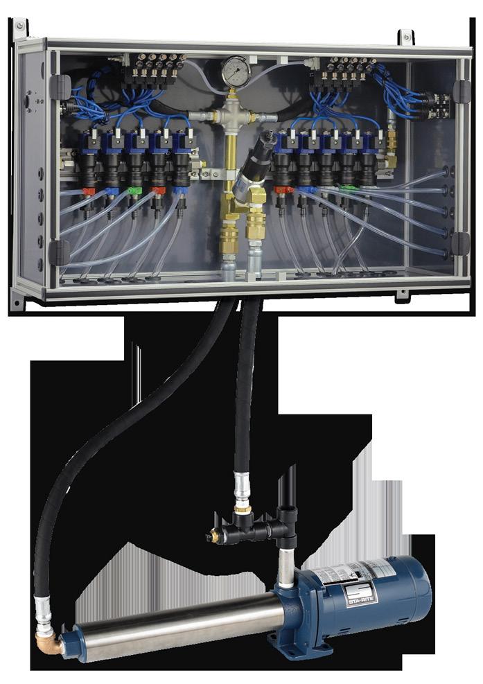
3 FEATURES OVERVIEW Consistent and accurate chemical application Flexible pump design flow rates FROM 10 to 40 GPM Compact design reduces footprint Pre-wired and pre-plumbed for fast installation Easy Plug-and-Play utility and chemical connections Modular design customized to your needs for up to 15 chemicals plus Tri-Foam Uses Hydra-Cannon Chemical Manifold Systems for easy and quick service Color-coded Chem-Flex Injectors using Quick-Change connections For new installations or retrofit in any car wash The AQUA-LAB will simplify the delivery of liquid chemicals to your car wash arch. Its plug-and play system is compact and pre-assembled for quick installation. To ensure that the AQUA-LAB will interface properly with your car wash facility, you must first verify that your facility has all of the proper space and connection requirements according to the specifications below. You must also verify that you have ordered the proper part number for your AQUA-LAB to match the requirements needed by your facility. SPECIFICATIONS UP to 15 Chemical Ports Up to 15 Pneumatic Ports Hydraulics operating pressure: 200 psi (Factory set) Pneumatics operating pressure: 100 psi (Factory set) Operating Ambient Temperature: Deg F Operate pumps with 208/230 or 480 Voltages (3-phase) Operate Solenoid Valves with 24VAC, 24VDC, 120VAC 1-1/2 water supply line (TX Model) 1 water supply line (AX & BX Models) Inlet pressure: 2-80 psi Space Requirements: a. Aqua Lab Systems i. TXF Model 3 x 3 footprint with 5 Clearance ii. TXW Model 2 wide x 4.5 high of wall space for system iii. AX Model 3 wide x 2 high of wall space for system iv. BX Model 1.5 wide x 2 high of wall space for system b. Pump Assemblies Pumps need to be within 3 of the system to allow connection of the two with just the included connection hose i. Single Pump 4 x 1 wall space ii. Dual Pump Wall mount 4 x 3 of wall space iii. Dual Pump Floor skid 4 wide x 1.5 deep footprint with 4 of Clearance c. Electrical Enclosures i. Motor Starter (AX and BX Models) 1 wide x 1.5 high of wall space ii. VFD Motor Controller 1.5 wide x 2 high of wall space iii. Terminal Box (Accessory) 1 wide x 1 high of wall space Hydra-Flex, Inc Page 1
4 INSTALLATION INSTRUCTIONS INSTALLATION SPECIFICATIONS The AQUA-LAB chemical delivery system has been designed for a fast and hassle free installation. It comes fully assembled with all of the components pre-wired and plumbed, leaving only the setting of equipment, and connection of the incoming and outgoing hoses and wires. As follows are the installation specifications for the AQUA-LAB: GENERAL: People Required: 2 people Mechanical Skill Level: Basic - Mounting equipment Electrical Skill Level: Advanced - Three phase power and knowledge of local codes is required Pneumatic Skill Level: Basic- pneumatic utility connection required Fluid Skill Level: Basic - Water utility connection required Chemical Knowledge: Advanced - Chemical titrations required TOOLS AND EQUIPMENT NEEDED: Unpacking: Normal hand tools Assembly: Normal hand tools Wiring: Normal electrical wiring tools Startup: Electrical meter helpful but not required ESTIMATED TIMELINE: Unpacking: minutes Frame Mounting: hours Fluid Connections: hours Motor & Valve Wiring: hours Startup & adjustment: hours UNPACKING The AQUA-LAB is shipped in a wooden crate for the purpose of protection. Before unpacking, be sure that the AQUA-LAB is on a level-flat surface. To unpack, perform these steps: 1. Open the crate using a drill with Phillips bit or Phillips head screwdriver 2. Cut the cellophane off of the AQUA-LAB by using a utility knife. Be sure to cut either at the corners or in an area where the knife will not damage the AQUA-LAB. 3. Using an adjustable wrench, un-bolt the AQUA-LAB from the pallet. 4. Lift the AQUA-LAB from the pallet. Use assistance if necessary. 5. Dispose of pallet, cellophane and additional packaging materials. Hydra-Flex, Inc Page 2
5 LOCATION AND MOUNTING **When selecting a location for any Aqua-Lab system make sure to consider the proximity to feed water, power supply, and the control cabinet that the valve signals will need to be wired from (or a junction box with the appropriate signals wires) as well as space near the system to store chemical containers. SPACE REQUIREMENTS: Aqua-Lab Systems TXF Model 3 x 3 footprint with 5 Clearance TXW Model 2 wide x 4.5 high of wall space AX Model 3 wide x 2 high of wall space BX Model 1.5 wide x 2 high of wall space Pump Assemblies (For TXW, AX, and BX Models) Pumps need to be within 3 of the system to allow connection of the two with just the included connection hose Single Pump 4 x 1 wall or floor space Dual Pump Wall mount 4 x 2.5 of wall space Dual Pump Floor skid 4 wide x 1.5 deep footprint with 4 of Clearance Electrical Enclosures Motor Starter (TXW, AX, and BX with Wall mount pump assembly) 1 wide x 1.5 high of wall space VFD Motor Controller (TXW, AX, or BX with Wall mount pump assembly) 1.5 wide x 2 high of wall space Terminal Box (Optional Item used if 30 signal cables do not reach car wash control cabinet) 1 wide x 1 high of wall space MOUNTING OF COMPONENTS: Aqua-Lab Systems TXF Position on the floor in optimal location, can be anchored with included anchor feet TXW Mount to concrete or cinder block wall with 4 concrete anchors AX Mount to concrete or cinder block wall with 4 concrete anchors BX Mount sturdy wall with 4 appropriate anchors Pump Assemblies Does not apply to TXF Single Pump Mount pump flange to concrete or cinder block wall or concrete floor with 4 concrete anchors **Needs to be within 3 of the Aqua-Lab system to connect them with the included connection hose Dual Pump Wall mount Mount to concrete or cinder block wall with 4 concrete anchors **Needs to be within 3 of the Aqua-Lab system to connect them with the included connection hose Dual Pump Floor skid Position on the floor near the feed water connection **Needs to be within 3 of the Aqua-Lab system to connect them with the included connection hose Electrical Enclosures Motor Starter (Pre mounted to the Frame for TXF) for other systems mount to the wall with 4 appropriate anchors VFD Motor Controller (Pre mounted to the Frame for TXF) for other systems mount to the wall with 4 appropriate anchors Terminal Box (Accessory) Mount to wall with 4 appropriate anchors **Location will depend on the position of the Aqua-Lab system and its proximity to the car wash control cabinet Hydra-Flex, Inc Page 3
6 FEED WATER CONNECTION **Prior to connection, please ensure that the feed lines are free of construction debris by flushing out the piping. Main Water Supply Line Size: AX and BX Models: 1 Female NPT; TXF and TXW Models: 1-1/2 Female NPT Keep at least 2 PSI in supply line when pump is in operation Maximum inlet pressure is 80 PSI If the pumps are fed from a tank, the water level must be at least 54 above pump at all times CHEMICAL LINE CONNECTIONS Chemical Inlet Connections Chemical tube recommendation: 1/4 ID Flexible PVC Tubing (Chemical Line Tubing) Run chemical line from storage container through the chemical access holes (Smaller diameter holes) and connect directly to the hose barb on the injector ensure that a foot valve or similar check valve/screen is attached at the end of the line in the storage container. Chemical Solution Connections Solution tube recommendation: 1/2 OD Poly Tubing Adapt hose to chemical injector using customer preferred connection type 3/8 & 1/2 OD Tube Push Fittings are provided Feed hose through solution outlet holes (Larger diameter holes) Metering tips will need to be installed to set dilution ratio - see Operation section below PNEUMATIC CONNECTIONS **IF AIR IS NOT REQUIRED FOR YOUR AQUA-LAB, PLEASE SKIP THIS SECTION Pneumatic Utility Connections: Flow and Pressure: 20 CFM, 100 PSI Max (Primary Regulator Factory Set, do not adjust) Incoming Connection Type and Size: 3/8 OD Hose Push Fitting Filter Included: Yes Regulator Included: Yes (Primary Regulator Factory Set, do not adjust) Lubricator Included: No Outgoing Connection Type and Size: 1/4 OD Hose Push to Connect Air Pressure Control: Individual Adjustable Regulators Air Flow Control: No **If there are unused air ports, either screw out the individual line regulator until air no longer flows or insert supplied plugs Hydra-Flex, Inc Page 4

7 ELECTRICAL CONNECTIONS **Use appropriate table below based on if your system has a Current Sensing and Timer Relays See Figure below to determine type of system. Timer Relay Current Sensing Relay Solenoid Valve Signal Connection **WITH CURRENT SENSING AND TIMER RELAYS STATION OR USE M12 LABEL ON BOX LABEL MAIN TRUCK CABLE WIRE COLOR Solenoid Valve Signal Connection Without Current Sensing and Timer Relays MANIFOLD POSITION* Ground N/A Green/Yellow N/A DO NOT USE N/A Blue N/A Hot / + N/A Brown N/A Station 1 1 White 1 Station 2 2 Green 2 Station 3 3 Yellow 3 Station 4 4 Grey 4 Station 5 5 Pink 5 Neutral / Common 6 Red N/A STATION OR USE M12 LABEL ON BOX LABEL MAIN TRUCK CABLE WIRE COLOR MANIFOLD POSITION* Ground N/A Green/Yellow N/A Neutral / Common N/A Blue N/A DO NOT USE N/A Brown N/A Station 1 1 White 1 Station 2 2 Green 2 Station 3 3 Yellow 3 Station 4 4 Grey 4 Station 5 5 Pink 5 DO NOT USE 6 Red N/A Hydra-Flex, Inc Page 5

8 **Manifold Positions Numbered from Left to Right Pump Power Connection and Signal Connection **208/230V or 480V 3-Phase Power required Motor Starter Version If receptacle plug accessory is included, simply plug the system into the wall outlet Wire each leg of the in coming power to the terminals labeled L1in, L2in, and L3in in the lower left of the enclosure. Make sure to follow all applicable electrical codes. VFD Version If receptacle plug accessory is included, simply plug the system into the wall outlet Wire each leg of the in coming power to the Main power switch in the top right of the enclosure, screw terminals labeled L1, L2, and L3. Make sure to follow all applicable electrical codes. PUMP PRIMING INSTRUCTIONS OPERATION 1. Refer to section II-g to ensure all electrical connections are complete. 2. Connect supply water with a 1 (AX and BX Models) or 1-1/2 (TX Model) Inlet Line and open feed line (Minimum 2 psi required) 3. Pull each pump discharge quick-connect until a steady stream of is flowing, and then reconnect. 4. Start the pumps one at a time using the motor starter. Ensure that pump rotation is correct as indicated on pump and that 200 psi can be reached. 5. TX Model: Slowly open the priming ball valve located off the end of the distribution block and allow water to flow until steady, then close the valve (a hose could be connected to the valve to the drain to avoid excessive water on the floor) 6. AX and BX Models: With the pump off disconnect the high pressure line to the AquaLab at the quick disconnect and point in a safe direction, while holding the line to control it start the pump and allow water to flow until steady. 7. Close the ball valve (TX Model) or reconnect the high pressure line at the quick disconnect (AX and BX Models) 8. Confirm that the pumps can obtain 200 psi and that the pump housing is cool to the touch after a minute in operation. 9. If pump does not prime, repeat steps 3-6!!Pay close attention to the temperature of the pump housing, if it starts getting hotter than the supply water then it is likely that the pump did not prime correctly!! *WARNING* If the pumps do not prime correctly they will heat up and it will cause damage to the pumps. WATER FLOW RATE AND CHEMICAL DILUTION SET UP For each of the chemicals that the Aqua-Lab is delivering to the car wash bay follow the steps outlined below to set the overall flow rate and chemical dilution. NOTE: you will need to know the target flow rate and chemical dilution (concentration) prior to setting up each chemical. Hydra-Flex, Inc Page 6
9 1. Using the Nozzle Size chart in the Appendix of this manual, follow the Feed Pressure column down to 200 (the operating pressure of the Aqua-Lab System). 2. Find the flow rate to the right of 200 that is closest to the desired target flow rate; from there follow that column back to the top of the chart to find the appropriate Nozzle size. 3. Using the Chemical Metering Rate chart in the Appendix of this manual, find the flow rate along the top that is closest to the flow rate you just determined in step 2 above. 4. Follow that column down until you find the dilution ratio (concentration) that is closest to the target value, then look to the Left of the chart to see which metering tip it corresponds to. NOTE: It may be necessary to change to a different injector s size based on the spray pattern and delivery of chemical to the vehicle. In that situation use the Nozzle size chart to determine the new flow rate at 200 psi and repeat steps 3 and 4 above to set the chemical usage. NOTE: The dilution ratios (concentrations) given in the Chemical Metering Rate Chart are based on drawing water through the tips. Some adjustments to a tip larger or smaller may be required due to the different of viscosities of the chemicals and water. POST INSTALLATION VACUUM & BACK PRESSURE CHECK If the spray nozzles on the arch are too small for the injector chosen, the back pressure put on the injector may cause the vacuum to not function and chemical will not be pulled The checks below are intended to help identify any potential issues that would cause the injector not to function correctly CHEM-FLEX INJECTOR VACUUM CHECK 1. At the Chem-Flex Injector, remove the chemical feed line from the injector hose barb. 2. Attached the tubing of the vacuum gauge to the Chem-Flex hose barb. 3. With the pump(s) on, manually activate the chemical that is to be tested at the main car wash control cabinet. An injector that is working properly will have a reading greater than or equal to ( ) 18 in Hg 4. Repeat steps 2-4 for each chemical lane that a vacuum reading is needed for. 5. Once testing is complete, turn off the Aqua-Lab pump from the main car wash control cabinet. CHEM-FLEX INJECTOR VACUUM CHECK Back Pressure is defined as the pressure that is created between the injector and the arch nozzles. It is caused by the chemical solution from the injector trying to push its way through the nozzle, the smaller the nozzles the harder it is to push through and consequently higher back pressure 1. Disconnect the outlet hose from the Chem-Flex injector that a back pressure reading will be taken for. 2. Connect the back pressure gauge assembly to the outlet of the Chem-Flex injector. 3. Connect the hose to the arch to the other end of the back pressure gauge assembly. **Make sure all hose barb fittings are secured with hose clamps. 4. Turn on the Aqua-Lab pump and the solenoid valve for the Chem-Flex being tested from the main car wash control cabinet The back pressure should not exceed 33% of the feed pressure (for the Aqua-Lab with the feed pressure set to 200 psi the back pressure should not exceed 66 psi). 5. Turn off the Aqua-Lab pump and solenoid valve at the main car wash control cabinet. 6. Remove the back pressure gauge assembly from the injector and reconnect the hose to the arch. **Make sure all hose barb fittings are secured with hose clamps. 7. Repeat steps 1-5 for each injector that a back pressure reading is needed for. Hydra-Flex, Inc Page 7
10 INDIVIDUAL INJECTOR FLOW RATE MEASUREMENT 1. Attach a short section of tubing (3-5 ft) to the outlet of the injector that you want to measure the flow rate of. 2. Turn on the Aqua-Lab pump and the solenoid valve for the Injector being tested. If possible have someone assist by turning them on while you keep the water from the short section of hose pointed in a safe direction. 3. Using a 2 liter graduated cylinder (or other large graduated cylinder) and a stop watch (watch or cell phone with a stop watch) Make sure the graduated cylinder is empty and that the stop watch is cleared. Direct the flow of water from the tube into the graduated cylinder and start the stop watch the instant you start adding water to the cylinder. Stop the timer when the cylinder is at least half full, preferably at a whole number level (ie. 1 liter, 2 liters) Divide the number of liters by the time in seconds then multiply by this will result in how many Gallons per minute (GPM) TROUBLESHOOTING The AQUA-LAB is supplied with the following tools to assist in set up and troubleshooting: Vacuum gauge for checking the vacuum at the chemical injector hose barb, Back Pressure Gauge for measuring back pressure downstream of the injector. PROBLEM POTENTIAL CAUSED SOLUTIONS Pump Operates, but delivers little or no water Pump won t start or run at full speed Excessive Noise from Pump Pump Leaks Injector is not drawing chemical - Passes Vacuum Pressure check test Inlet Restriction Low line voltage Inadequate water supply Undersized piping Leak on the Inlet side Worn or defective pump parts Pump not primed Incorrect Motor rotation Blown fuse or circuit breaker Defective Motor Starter contactor Incorrect Motor Voltage Defective motor Pump components damaged Pump not secured firmly Restricted Inlet Cavitation (Sounds like marbles in pump) Worn mechanical seal Worn o-ring seals Clogged chemical feed Check all in-line filters and inlet plumbing for restrictions Check pressure on inlet side of pump to be sure positive pressure is maintained Replace with larger piping Make sure connections are tight Replace worn parts or entire pump, Clean parts if required See priming instructions Reverse motor rotation by interchanging any two leads Replaced fuses or close circuit breaker Replaced motor starter contactor Voltage must be within 10% of motor rated voltage Replace motor Replace worn part or entire pump Secure properly Clean or correct restriction Increase inlet size Replace shaft seal Replace Check chemical hose, foot valve, metering tip and hose barb for debris or clogs Hydra-Flex, Inc Page 8

11 PROBLEM POTENTIAL CAUSED SOLUTIONS Injector is not drawing chemical - Fails Vacuum Pressure check test System won t regulate up to 200 psi Flow at arch is too low No flow from injector Valve stuck open Staying open when signal is off Too much back pressure on injector Clogged injector check valve Clogged injector nozzle Defective Injector Debris in regulator Opening to many valves at once Pump not primed Defective Check Valve Defective Regulator Defective Pump Incorrect Injector Flow Rate Selection System pressure too low Downstream pluming restrictive Solenoid valve malfunction Clogged Injector No water supply Debris in valve seat Perform back pressure check test outlined in Section IV if this manual. If the result is higher than 66 psi then Increase arch nozzle size or quantity, use larger tubing, or use a smaller flow injector Blow compressed air through the chemical hose barb on the injector to remove debris Remove injector and blow out any debris with compressed air If Vacuum check fails but Back Pressure is less than 66 psi, replace the injector Remove regulator and clean out debris System is limited to opening up to 8 valves at once or pressure will be greatly affected by so much demand Follow priming instructions Replace check valve if broken Replace Regulator Replace Pump Replace with desired injector size Ensure system pressure is set at 200 psi Perform Back pressure test outlined in Section IV of this manual, if over 66 psi, increase tube size and reduce elbows, turns or other restrictive plumbing Ensure valve is receiving the correct electrical signal and voltage Disassemble valve and clean out debris (See valve replacement instructions) Remove injector and blow out debris with compressed air Check that the system has a supply of water Remove and clean valve (See valve replacement instructions) VALVE REPLACEMENT INSTRUCTIONS Remove malfunctioning valves from the manifold making sure to unscrew it from the larger steel hex closest to the plastic body. On a clean work surface disassemble the valve assembly. Be cautious with the small components and noting how it is assembled. Inspect for debris that could interfere with the valves operation, paying particular attention to anything blocking the two small holes through the valve piston (2nd part from the left in the image below). For and correct assembly reference the image below. Hydra-Flex, Inc Page 9
12 APPENDIX: CHEM-FLEX INJECTORS - CHEMICAL DILUTION RATIOS NOTE: Dilution ratios given are based on drawing water through the metering tips and are meant as a starting point for system configuration. Results are expected to vary when drawing chemicals due to differences in viscosity and temperature. There may be slight variations of performance in injectors and metering tips that are unavoidable due to manufacture tolerances. Using the same tip color from site to site is a good starting point. However, with the potential for variation from part, to part it is reasonable to still need to do some adjustments from there. (Assumes feed pressure of 200 PSI (14 bar)) #8-32 METERING TIPS Flow Rate (GPM) at 200 PSI Injector Color White Yellow Tan Red Orange Gray Blue Light Blue Light Green Pink Purple Dark Green Black Black Black Black Nozzle Size (0.7 mm) (1.0 mm) (1.3 mm) (1.4 mm) (1.8 mm) (2.1 mm) (2.2 mm) (2.4 mm) (2.5 mm) (2.7 mm) (2.9 mm) (3.2 mm) (4.1 mm) (4.5 mm) (4.7 mm) (5.3 mm) COPPER 1: 57 1: 104 1: 155 1: 195 1: 281 1: 406 1: 468 1: 598 1: 629 1: 739 1: 881 1: : : : : 4259 PUMPKIN 1: 43 1: 82 1: 119 1: 126 1: 238 1: 348 1: 398 1: 519 1: 554 1: 647 1: 774 1: 946 1: : : : 3042 BURGUNDY 1: 34 1: 67 1: 97 1: 111 1: 207 1: 304 1: 347 1: 461 1: 495 1: 575 1: 690 1: 845 1: : : : 2469 LIME 1: 28 1: 57 1: 81 1: 100 1: 183 1: 270 1: 307 1: 414 1: 447 1: 518 1: 622 1: 764 1: 988 1: : : 1958 TAN 1: 28 1: 57 1: 81 1: 100 1: 183 1: 270 1: 307 1: 414 1: 447 1: 518 1: 622 1: 764 1: 826 1: : : 1557 ORANGE 1: 23 1: 44 1: 64 1: 78 1: 137 1: 196 1: 215 1: 293 1: 314 1: 365 1: 437 1: 536 1: 751 1: 874 1: : 1262 TURQUOISE 1: 17 1: 31 1: 45 1: 55 1: 91 1: 126 1: 134 1: 185 1: 197 1: 230 1: 274 1: 336 1: 561 1: 752 1: 885 1: 1099 PINK 1: 14 1: 24 1: 35 1: 42 1: 68 1: 93 1: 98 1: 130 1: 143 1: 159 1: 188 1: 224 1: 372 1: 473 1: 570 1: 728 LIGHT BLUE 1: 11 1: 17 1: 24 1: 31 1: 47 1: 64 1: 66 1: 93 1: 98 1: 114 1: 136 1: 166 1: 318 1: 406 1: 483 1: 572 BROWN 1: 10 1: 15 1: 22 1: 28 1: 43 1: 58 1: 59 1: 84 1: 88 1: 103 1: 122 1: 150 1: 270 1: 338 1: 408 1: 507 RED 1: 12 1: 17 1: 23 1: 34 1: 45 1: 46 1: 65 1: 69 1: 80 1: 95 1: 116 1: 202 1: 254 1: 306 1: 375 WHITE 1: 12 1: 16 1: 22 1: 31 1: 42 1: 43 1: 61 1: 64 1: 74 1: 88 1: 108 1: 180 1: 226 1: 272 1: 343 GREEN 1: 11 1: 14 1: 20 1: 28 1: 37 1: 38 1: 53 1: 55 1: 65 1: 76 1: 94 1: 160 1: 201 1: 241 1: 300 BLUE 1: 10 1: 12 1: 17 1: 23 1: 30 1: 31 1: 44 1: 46 1: 53 1: 63 1: 77 1: 122 1: 152 1: 185 1: 224 YELLOW 1: 9 1: 12 1: 16 1: 20 1: 22 1: 30 1: 31 1: 36 1: 42 1: 52 1: 80 1: 100 1: 120 1: 148 BLACK 1: 10 1: 13 1: 16 1: 17 1: 23 1: 24 1: 28 1: 33 1: 40 1: 61 1: 77 1: 92 1: 115 PURPLE 1: 6.6 1: 8.3 1: 9 1: 10 1: 13 1: 13 1: 15 1: 17 1: 21 1: 31 1: 39 1: 46 1: 57 GRAY 1: 5.3 1: 6.7 1: 6.9 1: 7.6 1: 9.9 1: 10 1: : 13 1: 16 1: 24 1: 30 1: 35 1: 44 OPEN 1: 4.9 1: 5.3 1: 5.2 1: 6.0 1: 6.1 1: 6.1 1: 7.6 1: 8.3 1: 10 1: 12 1: 15 1: 18 1: : 251 1: 503 1: 754 1: : : : : : : : : : : : : : 181 1: 363 1: 544 1: 726 1: : : : : : : : : : : : : 104 1: 208 1: 311 1: 415 1: 623 1: 831 1: 934 1: 835 1: 778 1: 898 1: : : : : : : 82 1: 165 1: 247 1: 329 1: 494 1: 659 1: 741 1: 642 1: 668 1: 755 1: : : : : : : 59 1: 119 1: 178 1: 238 1: 357 1: 475 1: 535 1: 487 1: 496 1: 558 1: : : : : : : 34 1: 68 1: 102 1: 136 1: 204 1: 272 1: 306 1: 282 1: 304 1: 344 1: 612 1: 748 1: : : : /7 polyflow (LLDPE) tubing is required to ensure a seal between the tube wall and the spiral plug. Hydra-Flex, Inc Page 10

, and the side of the box with 5 holes is for the")
. Each chemical bank of the Aqua-Lab is labeled as 1, 2, & 3.")
 Figure 4 4.")
 5. Repeat for all colors labeled.")
 Figure 5 7.")
")
13 Figure 1 TERMINAL BOX WIRING INSTRUCTIONS (OPTIONAL) The terminal box offers a simple way to locate the solenoid signal wires. Typically used when an existing system is removed, their signals can be brought to this box and terminated with the Aqua-Lab. INSTALLATION INSTRUCTIONS Figure 2 1. Determine location and hang terminal box. Note that the side of the box with three holes is for the Aqua-Lab control cables (yellow cables), and the side of the box with 5 holes is for the incoming activation signals from the wash controller. Orientate box accordingly and within reach of Aqua-Lab yellow cables 2. Remove Cover and notice the labeling of the terminals (Figure 2). Each chemical bank of the Aqua-Lab is labeled as 1, 2, & 3. For TX model this corresponds to top (1), middle (2), and bottom (3). For AX model this corresponds to left (1) and right (2) Figure 3 3. Bring the yellow cable from the corresponding chemical bank to the box and insert through cable gland as shown. (Figure 3) Figure 4 4. Using a small screwdriver, press into the spring terminal and pull away from the wire terminal to open the spring clamps. Insert the wire that corresponds to the labeled color then release the spring by removing the screw driver (Figure 4) 5. Repeat for all colors labeled. (brown and red are not used) 6. Blue and Green/Yellow are to be wired to the common and ground terminals which are segmented as shown (Figure 5) Figure 5 7. Repeat for all yellow Aqua-Lab cables 8. Individually insert chemical activation signals through cable glands and wire to desired chemical position (see wiring chart in operations manual) (Figure 6). Figure 6 9. Repeat for all chemical signals, only one of the common (blue) and ground (Green/yellow) wires for the signals need to be wired to the corresponding segmented terminals since they should be previously connected at the wash controller. You can wire up to three of the commons and grounds to ensure a redundant connection. 10. Lightly tug on all wires to ensure a good connection. Figure Replace Cover and tighten screws Hydra-Flex, Inc Page 11


14 REPLACEMENT PANEL, PUMP, & MCU PARTS LIST - AQUA-LAB AX/BX/TX or or or or Hydra-Flex, Inc Page 12
15 PART NAME PART NUMBER 1 Electric Solenoid Valve Replacement 24 VAC VDC VAC (Shown On Page 4) Hydra-Cannon Valve O-Ring Replacement Kit Single Black Hydra-Cannon Replacement Assembly /2 NPT Hydra-Cannon Manifold End Fitting Assembly Hydra-Cannon Interface Fitting Assembly M12 Junction Block - 6 Port, With 30 Homerun Cable M12 Junction Block - 6 Port, With 100 Homerun Cable M12 X Din A X Din I Splitter Cable M12 X Din A X Din I Splitter Cable Medium M12 X Din A X Din I Splitter Cable Long M12 X Din A Cable Outlet Pressure Gauge PSI Bottom Mount /4 Hose Barb Foaming Air Check Valve Pneumatic Replacement Valve With Regulator 24 VAC VDC VAC Pisco Regulator Replacement Primary Air Regulator (BX Only) Primary Air Regulator (AX & TX) Primary air regulator Replacement Bowl - Aluminum Primary air regulator Replacement Bowl - Plastic Male Quick Connect - Brass Female Quick Connect - Brass /4 Male Quick Connect - Brass /4 Female Quick Connect - Brass /2 Male Quick Connect - Brass /2 Female Quick Connect - Brass Wye Strainer - 20 Mesh NPT T16 Wye Strainer Screen & Gasket Kit /2 Ball Valve - Brass Thermal Relief Valve - 1/2 NPT GPM Bypass Pressure Regulator - Stainless Steel Manifold Inlet 1/2 ID Hose X 1/2 NPT Ends - 72 Long GPM Quick Connect Regulator Plumbing Assembly Replacement/Backup 20 GPM Pump Outlet Manifold Check Valve - Brass Quick Connect 9 Cordset For Pump Quick Connect Pump Plug - Female Thermal Overload - Sprecher & Schuh Timer Relay Current Sensor - AC Current Sensor - DC Contactor - Sprecher & Schuh 24 VAC VDC VAC M12 Cordset (Grey) /4 x 72 Hose Hydra-Flex, Inc Page 13
16 Hydra-Flex, T: Inc F: Page reva0717
AQUA-LAB SD CHEMICAL DISPENSING SYSTEM. User Manual REV G revg0518
 AQUA-LAB SD CHEMICAL DISPENSING SYSTEM User Manual REV G 4000061 revg0518 Hydra-Flex, Hydra-Flex, Inc. 2018 Inc. 2017 TABLE OF CONTENTS Specifications 1 Aqua-Lab SD System Diagrams 2 Layout Drawing 4 Estimated
AQUA-LAB Chemical Dispensing System. Operating Manual REV L
 AQUA-LAB Chemical Dispensing System Operating Manual REV L Specifications 1. Operating water pressure: 200 psi (Factory set) 2. Pneumatics operating pressure: 100 psi (Factory set) 3. Maximum water source
AQUA-LAB MD CHEMICAL DISPENSING SYSTEM. User Manual REV V revv0118
 AQUA-LAB MD CHEMICAL DISPENSING SYSTEM User Manual REV V 0000 revv08 Hydra-Flex, Hydra-Flex, Inc. 08 Inc. 08 Page TABLE OF CONTENTS Specifications Layout Drawings Booster Pump & MCU Layout Drawings Grundfos
AQUA-LAB MD/XD GEN2 & HD
 AQUA-LAB MD/XD GEN & HD CHEMICAL DISPENSING SYSTEM User Manual REV D 0009 revd08 Hydra-Flex, Hydra-Flex, Inc. 08 Inc. 08 Page TABLE OF CONTENTS Specifications Layout Drawing Estimated Installation Timeline
AQUA-LAB HD/XD CHEMICAL DISPENSING SYSTEM. User Manual REV L revl1018
 AQUA-LAB HD/XD CHEMICAL DISPENSING SYSTEM User Manual REV L 000087 revl08 Hydra-Flex, Hydra-Flex, Inc. 08 Inc. 08 Page TABLE OF CONTENTS Specifications Layout Drawing Panel Diagram Estimated Installation
AQUA-LAB HD/XD CHEMICAL DISPENSING SYSTEM. User Manual REV F revf0917
 AQUA-LAB HD/XD CHEMICAL DISPENSING SYSTEM User Manual REV F 4000087 revf0917 Hydra-Flex, Hydra-Flex, Inc. 2017 Inc. 2017 Page 1 TABLE OF CONTENTS Specifications 3 Layout Drawing 4 Panel Diagram 5 Estimated
AQUA-LAB MD/XD GEN2 & HD
 AQUA-LAB MD/XD GEN2 & HD CHEMICAL DISPENSING SYSTEM User Manual REV B 4000129 revb1117 Hydra-Flex, Hydra-Flex, Inc. 2017 Inc. 2017 Page 1 TABLE OF CONTENTS Specifications 3 Layout Drawing 4 Estimated Installation
AQUA-LAB SD GEN2 CHEMICAL DISPENSING SYSTEM. User Manual REV B revb0518
 AQUA-LAB SD GEN2 CHEMICAL DISPENSING SYSTEM User Manual REV B 4000122 revb0518 Hydra-Flex, Hydra-Flex, Inc. 2018 Inc. 2018 Page 1 TABLE OF CONTENTS Specifications 3 Layout Drawing 4 Panel Diagram 5 Motor
DEMA MODELS P203CTC.PI.1,.2,.3 INSTALLATION INSTRUCTIONS
 I. PARTS: A. 1 pc. Cyclone Portable Injector B. 1 pc. Foot Strainer & 1/4" I.D. Tubing. C. 1 pc. Ceramic Weight. D. 1 pc. Instruction Sheet D. 2 pc. 3 hose w/ female x female GHT fittings on both ends
BUG PREP KIT 2.0 HAND-PREP SYSTEM. User Manual REV A reva0616
 BUG PREP KIT 2.0 HAND-PREP SYSTEM User Manual REV A 4000110 reva0616 Hydra-Flex, Hydra-Flex, Inc. 2016 Inc. 2016 Page 1 TABLE OF CONTENTS Overview 3 Standard Bug Prep Kit 2.0 3 Bug Prep Retro Controller
PROMAX INSTRUCTION MANUAL
 PROMAX INSTRUCTION MANUAL One Hand Activation Single Product [1 gpm (4l/m) models only] One Hand Activation 4 Product [1 gpm (4l/m) models only] Button Activation Single Product [1, 4, 8 gpm (4, 16, 30
TABLE 1-1 GPM FLOW RATE PROPORTIONER, 1/4 I.D. TUBING Injection Rates For Viscosities Shown Metering Tip Color
 Blend Safe II Dispensing System is a modular, locking dispensing system that allows user to dispense chemicals safely, control dispenser inventory and has the flexibility in the field to meet changing
TRIPLE FOAM INSTALLATION MANUAL Part # FOAMSTRMRTPL00X
 TRIPLE FOAM INSTALLATION MANUAL Part # FOAMSTRMRTPL00X TABLE OF CONTENTS Equipment Specifications Page: 1 Suggested Tools and Installation Materials Page: 2 Installation Instructions Page: 2 Initial Start-Up
DEMA SPRAY CLEAN DISPENSERS MODEL 605T INSTALLATION INSTRUCTION
 The 605T Spray Clean Dispenser is used in any application where a chemical product must be sprayed or foamed without the use of compressed air or a high pressure pump. City water pressure and optional
DEMA SPRAY STATION II MODEL 606T-2 INSTALLATION INSTRUCTIONS
 The 0T-2 Spray Station II Dispensers are used in any application where a chemical product must be sprayed or foamed without the use of compressed air or a high pressure pump. City water pressure and optional
DEMA 651AG SINGLE-FEED INSTALLATION INSTRUCTIONS
 I. PARTS: A. Dispenser assembly B. 1 pc. 9/16 in. I.D. X 6 ft. vinyl outlet tubing (4 GPM proportioner only). C. 1 pc. 3/8 in. O.D. X 8 ft. vinyl supply tubing, foot valve & ceramic weight. D. 4 pc. #10
VEHICLE WASH CATALOG VOLUME
 VEHICLE WASH CATALOG VOLUME 3 www.hydraflexinc.com 952-808-3640 952-808-3640 www.hydraflexinc.com 53 INDEX ABOUT US CHEMICAL DISPENSING SYSTEMS Aqua-Lab System Benefits Next Generation Features Aqua-Lab
The 606T-2 unit is designed to be used as a spray or foam unit where up to two chemicals can be attached to the unit along with a clean water rinse.
 Overview The 606T-2 unit is designed to be used as a spray or foam unit where up to two chemicals can be attached to the unit along with a clean water rinse. The unit features three ball valves for control
Spray & Foam Dispenser Item #
 Spray & Foam Dispenser Item #92364-00 Spray & Foam Dispenser Item #92364 Table of Contents Section Page 1. Spray & Foam Dispenser Description... 3 2. Spray & Foam Dispenser Installation... 4 3. Chemical
DEMA MODELS 606T INSTALLATION INSTRUCTIONS
 I. PARTS: A. Select-O-Spray Assembly B. 2 Pcs. Foot Strainers & 1/4" ID Tubing C. 4 Pcs. Mounting Screws & Anchors D. 1 Pc. 100-15K Metering Tip Kit TABLE 1 Hose I.D. 3/8" 1/2" 5/8" Max. Length 15 ft.
DEMA SINGLE-FEED MODEL: 651GAP& 651GAP-1 INSTALLATION INSTRUCTIONS
 The Model 65GAP is designed to dispense one product into a kitchen sink with the turn of a ball valve. I. PARTS: ITEM DESCRIPTION QTY. A Dispenser Assembly B ½ ID X 6 Long Vinyl Outlet Tubing (For 4 GPM
PeroxiDraw Dispenser
 The PeroxiDraw Dispensing System is a locking dispensing system that allows the user to dispense Green Earth Peroxide Cleaner for up to six different dilutions and applications safely and effectively.
665 Series Dispenser. Metering tip kit
 665 Series Dispenser Metering tip kit Box Contains Mounting hardware, template & key set Instruction sheet 665 series dispenser 4 SafeLink cap assemblies OR Bulk tubing, 4 ceramic weights and foot valves
DEMA BLEND CENTER MODELS: 633GAP INSTALLATION INSTRUCTIONS
 The 633GAP Series Blend Center modular design lets you easily couple together any number of stations to create a system that meets your specific needs. Mix and match both high and low flow units for filling
Tools Needed for Mounting Cleá Filling Station
 ALWAYS OBSERVE PRODUCT SAFETY AND HANDLING INSTRUCTIONS. ALWAYS DIRECT DISCHARGE AWAY FROM YOU or other persons. ALWAYS DISPENSE CLEANERS AND CHEMICALS AS DIRECTED ON THE LABEL. ALWAYS DISPENSE INTO APPROVED
DEMA 652 DUO-FEED INSTALLATION INSTRUCTIONS
 I. PARTS: A. Dispenser assembly B. 1 pc. ½ in I.D. X 6 ft. vinyl outlet tubing C. 1 pc. 9/16 in. I.D. X 6 ft. vinyl outlet tubing. D. 2 pc. 3/8 in. O.D. X 8 ft. vinyl supply tubing, foot valve & ceramic
Cleaning Systems Inc. 2 P Rev:03
 CHEMPOD Table of Contents Overview... 3 Specifications... 3 Dimensions... 3 Weight... 3 Electrical Voltage... 3 Capacity... 3 Product Supply... 3 Pneumatic Supply... 3 Optional Installation Kits... 3 Locating
Spray Clean 606T-2 Installation Instruction
 Spray Clean 606T-2 Installation Instruction Overview The 606T-2 unit is designed to be used as a spray or foam unit where up to two chemicals can be attached to the unit along with a clean water rinse.
DEMA BLEND CENTER MODEL 681GAP-3 INSTALLATION INSTRUCTIONS
 1. PARTS CHECKLIST: A. Blend Center Assembly B. Vinyl Supply Tubing with Foot Valve Assembly C. Ceramic Weight D. Vinyl Outlet Tubing E. Screw and Anchor Kit F. Label Card G. Metering Tip Kit 2. INSTALLATION:
Items # and #
 D I S P E N S E R T E C H N I C A L M A N U A L Items #91160-00 and #91161-00 1. System Description... 1 2. Equipment Included with the Green Earth II XL System... 2 3. Components Included with Green Earth
Compact Cleaning System
 Series 9900 Compact Cleaning System THANK YOU FOR CHOOSING OUR PRODUCTS Please use this equipment carefully and observe all warnings and cautions. WEAR ALWAYS protective clothing and eyewear when working
CHEMTROL TRIPLE SPACE SAVER CLEANING STATION #U16242 INSTALLATION INSTRUCTIONS
 CHEMTROL TRIPLE SPACE SAVER CLEANING STATION #U16242 INSTALLATION INSTRUCTIONS 1) PARTS INCLUDED: A. Cleaning Station. B. 3 ea. 3/8" OD x 8' long vinyl chemical supply tubing w/ cap adapter C. 1 ea. 3/4"
ALWAYS DISCONNECT DISPENSER FROM WATER SOURCE WHEN DISPENSER IS NOT IN USE.
 1060GAPRF With dilution selector 1060GAP OVERVIEW DEMA S MPD is a multiple product and dilution dispenser designed for use with SafeLink closed loop inserts. With its innovative patent pending QuickDock
Dilution Control Systems. 2-Button Station Model OPERATION SERVICE PARTS CARE
 Dilution Control Systems 2-Button Station Model 421090 OPERATION SERVICE PARTS CARE Note: 2-Button Station comes in two separate cartons identified as Carton 1 and Carton 2. Revised 1/02 2-Button Station
DEMA MODEL 606T-WI INSTALLATION INSTRUCTIONS
 DEMA MODEL 606T-WI INSTALLATION INSTRUCTIONS I. PARTS: A. Select-O-Spray Assembly B. 2 Pcs. Foot Strainers & 1/4" ID Tubing C. 4 Pcs. Mounting Screws & Anchors D. 1 Pc. 100-15K Metering Tip Kit E. 1 Pc.
DEMA MODEL 693T FOAM STATION II INSTALLATION INSTRUCTION
 1. PARTS CHECKLIST: 2. INSTALLATION: DEMA MODEL 93T FOAM STATION II ITEM DESCRIPTION QTY. A. Foam Station Assembly 1 B. ¼ ID Tubing & Foot Strainer 1 C. 3/ ID Tubing & Foot Strainer 1 D. Ceramic Weight
DEMA MODEL 603T-WI INSTALLATION INSTRUCTIONS
 DEMA MODEL 603T-WI I. PARTS: A. Select-O-Matic Assembly B. 2 Pcs. Foot Strainers & 1/4" ID Tubing C. 4 Pcs. Mounting Screws & Anchors D. 1 Pc. 100-15K Metering Tip Kit (603T Only) E. 1 Pc. Backflow Preventer
DEMA MODEL 692T FOAM STATION I INSTALLATION INSTRUCTION
 1. PARTS CHECKLIST: ITEM DESCRIPTION QTY. A. Foam Station Assembly 1 B. #10 Screw & Anchor Kit Set (Total: 4 Screws & 4 Anchors) 1 C. Ceramic Weight 1 D. ¼ ID Tubing & Foot Valve Assembly 1 E. Metering
INSTRUCTIONS. Fc. -1,<" SERIES ST-261 REGULATING UNLOADER VALVE
 INSTRUCTIONS Fc. -1,
DEMA RAPID FIRE MODELS 6300, , , , 6310, 6300H 6300E, 6300EH, &6310E INSTRUCTION SHEET
 I-1002 Pg. 1 of 12 PURPOSE: The RAPID FIRE is a spray system designed with a single knob to control OFF, RINSE and up to two chemicals using a single chemically resistant plastic injector. There is full
FRP SystemOne GELCOATER OPERATION MANUAL. MAGNUM VENUS PRODUCTS Operation Manual. Part No. M Revision
 1300-1-1 GELCOATER OPERATION MANUAL MAGNUM VENUS PRODUCTS Operation Manual Part No. M1300-1-1 Revision 04.26.01 Operation Manual Unit Information Unit # Type Of: Power Cylinder Metering Pump Gun Fluid
SINGLE-STAGE INJECTOR MODELS 200-3C, 200C, 201C, 202C, 203C, 204C, 206C, 208C
 D E M A SINGLE-STAGE MODELS SINGLE-STAGE MODELS 1. PARTS A. Injector B. Backup washer (Models 204C & smaller). C. Ceramic Weight. D. Tubing 8 long w/ foot strainer. E. Three brass nozzle bushings Metering
Mizer Single Pump and Starter Box
 Mizer Single Pump and Starter Box Table of Contents Line Diagram... 2 Overview... 3 Booster Pump Specifications... 3 Water... 3 Electrical... 3 Models... 3 Mounting... 4 Electrical... 6 Motor Rotation...
(Airgap)
") 92174-00 91599-00 (Airgap) Technical Manual EQUIPMENT PACKING LIST FASTDRAW PRO Dispenser with attached 6 water inlet hose Keys (2) Hose Hook Technical Manual Operation Chart Wall Anchors (4) and Screws
92174-00 91599-00 (Airgap) Technical Manual EQUIPMENT PACKING LIST FASTDRAW PRO Dispenser with attached 6 water inlet hose Keys (2) Hose Hook Technical Manual Operation Chart Wall Anchors (4) and Screws
DEMA DILUTION-AT-HAND EXTREME 800 Series Chemical Dispensers
 DEMA DILUTION-AT-HAND EXTREME 800 Series Chemical Dispensers Overview The DILUTION-AT-HAND EXTREME chemical dispenser series combines the proven technology of the DEMA DILUTION-AT-HAND with a new look
DEMA 258BD-200C and 258BT-200C DRAIN MASTER Jr. INSTALLATION INSTRUCTION SHEET
 I-736 Pg. 1 of 10 Summary The 258BD-200C Drain Master is designed to feed chemicals into drains and grease traps to break up grease, detergent buildup and eliminate odors. The 258BT-200C Trash Master is
ICS Integrated Cleaning System. Rechargeable Battery
 ICS 8900 Integrated Cleaning System Rechargeable Battery THANK YOU FOR CHOOSING OUR PRODUCTS Hydro Systems manufactures quality chemical proportioners. Please use this equipment carefully and observe all
Certo Chemical Dilution System
 Certo Chemical Dilution System Overview The Certo Chemical Dilution System accurately dilutes chemical concentrates with water and dispenses the diluted mixture at either a high flow rate to fill buckets
Intended Use: Explanation of Signal Word Consequences
 SAFETY INFORMATION & INSTRUCTION MANUAL Please read, understand, and follow all safety information contained in these instructions prior to the use of this device. Retain these instructions for future
LIQUIDYNAMICS Light Viscosity Bulk Transfer Cart
 This manual contains important warnings and information. READ AND KEEP FOR REFERENCE. LIQUIDYNAMICS Light Viscosity Bulk Transfer Cart Instruction & Parts Manual This Manual Covers P/N 33271 P/N 33271
Purging Air From Divider Block Lubrication Systems
 FROST ENGINEERING SERVICE Purging Air From Lubrication Systems A D I V I S I O N O F G E C S E Y S A L E S & S E R V I C E DESCRIPTION Divider block lubrication systems operate correctly only when all
3.1 DISPENSER BLACK SHADOW SERIES. Tools Needed for Mounting SCS Dispenser Hammer
 SCS 2 BLACK SHADOW SERIES 3.1 DISPENSER ALWAYS OBSERVE PRODUCT SAFETY AND HANDLING INSTRUCTIONS. ALWAYS DIRECT DISCHARGE AWAY FROM YOU or other persons. ALWAYS DISPENSE CLEANERS AND CHEMICALS AS DIRECTED
DEMA Pro-Fill I Sink Dispenser
 DEMA Pro-Fill I Sink Dispenser MODELS PF651GAP, PF651AG, PF651GAP-1M, & PF651AG-1M Overview The PRO-FILL I Sink Dispenser mixes water with a cleaning chemical and dispenses the solution into holding containers
DEMA SPRAY CLEAN MODELS: 244CDF & 244CDFT INSTALLATION INSTRUCTIONS
 I. PARTS: A. Injector. B. Spray gun. C. Mounting screws and washers. D. Vinyl supply tubing, foot strainer & ceramic weight. E. Metering tip (specified size, model 244CDFT only). II. INSTALLATION: (See
DEMA MODEL 604T-WI INSTALLATION INSTRUCTIONS
 DEMA MODEL 604T-WI I. PARTS: A. Select-O-Matic Assembly B. 2 Pcs. Foot Strainers & 1/4" ID Tubing C. 4 Pcs. Mounting Screws & Anchors D. 1 Pc. 100-15K Metering Tip Kit (604T Only) E.1 Pc. Backflow Preventer
SERVICE PARTS LIST SPECIFY CATALOG NO. AND SERIAL NO. WHEN ORDERING PARTS 13 HP DIRECT DRIVE PRESSURE WASHER CATALOG NO
 SPECIFY CATALOG NO. AND SERIAL NO. WHEN ORDERING PARTS HP DIRECT DRIVE PRESSURE WASHER CATALOG NO. 555-22 SERVICE PARTS LIST STARTING SERIAL NUMBER B06A REVISED BULLETIN PAGE OF BULLETIN NO. 5-20-000 DATE
DEMA SPRAY CLEAN MODELS: 244BC, 244BCE, 244BCP & 244BCT INSTALLATION INSTRUCTIONS
 I. PARTS: A. Injector. B. Spray gun. C. Mounting screws and washers. D. Vinyl supply tubing, foot strainer & ceramic weight. E. Metering tip (specified size, model 244BCT only). II. INSTALLATION: (See
DEMA Pro-Fill II Sink Dispenser
 DEMA Pro-Fill II Sink Dispenser MODELS PF652GAP, PF652AG, PF652GAP-2M, & PF652AG-2M Overview The PRO-FILL II Sink Dispenser mixes water with cleaning chemicals and dispenses these solutions. This unit
MOTOR CITY ROCKERZ INSTALLATION MANUAL Part # ROCKRHYD[... ] ROCKRELE[... ] (ALL COLORS)
![MOTOR CITY ROCKERZ INSTALLATION MANUAL Part # ROCKRHYD[... ] ROCKRELE[... ] (ALL COLORS)](/thumbs/89/99803499.jpg "MOTOR CITY ROCKERZ INSTALLATION MANUAL Part # ROCKRHYD[... ] ROCKRELE[... ] (ALL COLORS)") MOTOR CITY ROCKERZ INSTALLATION MANUAL Part # ROCKRHYD[....... ] ROCKRELE[....... ] (ALL COLORS) TABLE OF CONTENTS Equipment Specifications Page: 1 Equipment Features Page: 1 Suggested Tools and Installation
MOTOR CITY ROCKERZ INSTALLATION MANUAL Part # ROCKRHYD[....... ] ROCKRELE[....... ] (ALL COLORS) TABLE OF CONTENTS Equipment Specifications Page: 1 Equipment Features Page: 1 Suggested Tools and Installation
INSTALLATION INSTRUCTIONS DEMA BLEND CENTER MODEL B-GAP, T-GAP
 1. PARTS: ITEM DESCRIPTION QTY. A. Blend Center Assembly 1 B. ¼ ID X 8 Long Vinyl Supply Tubing & Foot Valve Assembly 1 C. Ceramic Weight 1 D. ½ ID X 6 Long Vinyl Outlet Tubing (For 4 GPM Station Only)
WATCH GUARD 440 SERIES FLOAT VALVES INSTALLATION INSTRUCTIONS MODELS: T, TX, T, BT,
 WATCH GUARD 440 SERIES FLOAT VALVES INSTALLATION INSTRUCTIONS MODELS: 440-22T, 440-22TX, 440-23T, 440-23BT, 440-24 Overview The Watch Guard 440 Series of float valves fills and maintains fluids in reservoirs.
FRS Dispenser (Foam-Rinse-Sanitize) Model # ol Systems. Dilution Control OPERATION SERVICE PARTS CARE
 Model # ol Systems. Dilution Control OPERATION SERVICE PARTS CARE") Dilution Control ol Systems FRS Dispenser (Foam-Rinse-Sanitize) Model #421330 OPERATION SERVICE PARTS CARE Revised 11/03 This dispesner is used with the Travel Station Model #421250 or the Sanitation Station
Dilution Control ol Systems FRS Dispenser (Foam-Rinse-Sanitize) Model #421330 OPERATION SERVICE PARTS CARE Revised 11/03 This dispesner is used with the Travel Station Model #421250 or the Sanitation Station
MicroCoat System Operating Manual MC4000 Series MC785M, MC785M-WF Spray Valves
 MicroCoat System Operating Manual MC Series MC785M, MC785M-WF Spray Valves A NORDSON COMPANY Introduction The MicroCoat System provides precise lubrication control for metal stamping operations. The MC
SAFETY INFORMATION & INSTRUCTION MANUAL
 SAFETY INFORMATION & INSTRUCTION MANUAL Please read, understand, and follow all safety information contained in these instructions prior to the use of this device. Retain these instructions for future
Model AM2 M40 Panel Installation, Operation, and Maintenance Manual
 Model AM2 M40 Panel Installation, Operation, and Maintenance Manual RECEIVING AND INSPECTION Upon receiving unit, check for any interior and exterior damage, and if found, report it immediately to the
MicroCoat. System Operating Manual MC2000 Series. MC785, MC785-WF Spray Valves. US: UK: Mexico:
 MicroCoat System Operating Manual MC2 Series MC785, MC785-WF Spray Valves A NORDSON COMPANY US: 8-498-8865 UK: 8 585733 Mexico: 1-8-556-3484 Introduction The MicroCoat System provides precise lubrication
DEMA BLEND CENTER MODELS: 637GAP-1 and 637GAP-4 INSTALLATION INSTRUCTIONS
 1. PARTS CHECKLIST: ITEM DESCRIPTION QTY. A. Blend Center Assembly 1 B. ¼ ID X 8 Long Vinyl Supply Tubing & Foot Valve Assembly 4 C. Ceramic Weight 1 D. ½ ID X 6 Long Vinyl Outlet Tubing (For 1 GPM Station
T-Dolly Troubleshooting Guide
 T-Dolly Troubleshooting Guide Complete following items before beginning troubleshooting 1. Place wheel chocks and jack stands in place per the BLOCKING DIAGRAM decal. Located on the underside of the pump
DEMA SPRAY CLEAN MODELS: 241CDF & 241CDFT INSTALLATION INSTRUCTIONS
 1. PARTS A. Bottle holder and injector assembly. B. Spray gun (Model 40-8B). C. 4 mounting screws in envelope. 2. INSTALLATION Mount the bottle holder on wall using the 4 screws provided through the plates
THANK YOU FOR CHOOSING BATHERBOX GETTING STARTED WHAT S IN THE BOX? N. Northview Ave Sioux Falls, SD 57107
 INSTRUCTION MANUAL THANK YOU FOR CHOOSING BATHERBOX You are on your way to creating an unmatched bathing experience both for you and the lucky animal. The BatherBox is designed to save you hours of time
Troubleshooting. This section outlines procedures for troubleshooting problems with the operation of the system:
 Troubleshooting This section outlines procedures for troubleshooting problems with the operation of the system: 4.1 System Error Messages... 4-2 4.2 Prep Station Troubleshooting... 4-6 4.2.1 Adapter Not
OWNER S MANUAL. Model: LG-30-TRL ( ) (30 Gallon Lawn & Garden Trailer Sprayer)
 (30 Gallon Lawn & Garden Trailer Sprayer)") OWNER S MANUAL Model: LG-30-TRL (5302317) (30 Gallon Lawn & Garden Trailer Sprayer) Technical Specifications 30 Gal. Corrosion-Resistant Polyethylene Tank 12 Volt Diaphragm Pump, 2.1 g.p.m. 60 psi 15 Ft.
OWNER S MANUAL Model: LG-30-TRL (5302317) (30 Gallon Lawn & Garden Trailer Sprayer) Technical Specifications 30 Gal. Corrosion-Resistant Polyethylene Tank 12 Volt Diaphragm Pump, 2.1 g.p.m. 60 psi 15 Ft.
Model and Series 115 VAC INDUSTRIAL DIAPHRAGM PUMPS. PumpAgents.com - buy pumps and parts online INDUSTRIAL DIAPHRAGM PUMPS
 Model 31801 and 31800 Series 115 VAC INDUSTRIAL DIAPHRAGM PUMPS INDUSTRIAL DIAPHRAGM PUMPS FEATURES Run Dry Ability Self-Priming Thermal Overload Protected Motor Easy Installation Low Amp Draw Compact
Troubleshooting Guide: Elevance Delivery Systems
 Troubleshooting Guide: Elevance Delivery Systems FOR USE BY MIDMARK TRAINED TECHNICIANS Contents Description / Links Troubleshooting Charts ICM Screens Assistant s Unit Instruments (Elevance & European)
Technical Manual. Table of Contents
 Technical Manual Table of Contents Section Page 1. FASTDRAW System Description... 2 2. FASTDRAW Equipment Available... 3 3. FASTDRAW Equipment Packing Lists... 3 4. Parts Diagram... 4 5. Pre-Installation
Adjustable Purge Valve
 U S E R G U I D E UGC031-0508 www.conairgroup.com Adjustable Purge Valve Single and Dual APV Models Corporate Office: 724.584.5500 l Instant Access 24/7 (Parts and Service): 800.458.1960 l Parts and Service:
PACIFIC Recumbent Height-Adjustable Bath System Parts Breakdown and Assembly Manual
 PACIFIC Recumbent Height-Adjustable Bath System 9700 Parts Breakdown and Assembly Manual Panel 390010-1 Tubs 390011-1 or 390022-1 390748 Revision H 4/1/2014 PENNER PATIENT CARE, INC Box 523 / 101 Grant
HALLMARK INDUSTRIES INC
 Performance Part No. HP. CONVERTIBLE JET PUMP USER S MANUAL GPH of Water @ Total Discharge Pressure of 40 psi Max. Pressure Max suction (shallow well) Max Suction (deep well) Max GPM (@0 head) Max Discharge
F2B and S2S MITTERS INSTALLATION MANUAL Part # MTTRF360 [... ] and MTTRS360 [... ] ( ALL COLORS )
![F2B and S2S MITTERS INSTALLATION MANUAL Part # MTTRF360 [... ] and MTTRS360 [... ] ( ALL COLORS )](/thumbs/90/103874314.jpg "F2B and S2S MITTERS INSTALLATION MANUAL Part # MTTRF360 [... ] and MTTRS360 [... ] ( ALL COLORS )") Equipment Features F2B and S2S MITTERS INSTALLATION MANUAL Part # MTTRF360 [.... ] and MTTRS360 [.... ] ( ALL COLORS ) Aluminum Structure Color Skinz Snap On Structure Wrap 4 Baskets over-lapping design
Equipment Features F2B and S2S MITTERS INSTALLATION MANUAL Part # MTTRF360 [.... ] and MTTRS360 [.... ] ( ALL COLORS ) Aluminum Structure Color Skinz Snap On Structure Wrap 4 Baskets over-lapping design
LG-60-3PT-WP-309-BL-TSC
 55 Model No: LG-0-PT-WP-0-BL-TSC 0 Gallon Point Lawn & Garden Sprayer W/Pump & Coupler & Boomless Boom Assembly / Operation Instructions / Parts ASSEMBLY Most of the sprayer has been assembled at the factory..
LAWN SPRINKLER, IRRIGATION PUMP
 LAWN SPRINKLER, IRRIGATION PUMP MODEL #, SP0P, SP5P, SP20P, EL0P, EL5P, EL20P SAFETY INFORMATION Please read and understand this entire manual before attempting to assemble, operate or install the product.
To ensure proper installation, digital pictures with contact information to before startup.
 Check List for Optimal Filter Performance? There should be no back-pressure on the flush line. A 1 valve should have a 2 waste line, and 2 valve should have a 3 waste line. Do not use rubber hosing or
TABLE 1. * SPECIFY S Stainless Steel Knob Part No S or Part No ST (for tips) for pressure exceeding 700 PSI.
 for pressure exceeding 700 PSI.") 1. PARTS A. Injector B. Ceramic Weight. C. Plastic tubing 8' long with foot strainer. 2. INSTALLATION The injector may be installed in any position in the water line with the arrow in the direction of
1. PARTS A. Injector B. Ceramic Weight. C. Plastic tubing 8' long with foot strainer. 2. INSTALLATION The injector may be installed in any position in the water line with the arrow in the direction of
ON DEMAND INSTALLATION GUIDE
 ON DEMAND INSTALLATION GUIDE PICTOGRAMS Each Signifier displayed here is specific to this User Manual. Menu Previous Advance Note Tip Example Barcode Scanner Rotary Heads Drum & Frame Pump Stations Control
PowerAir Compressor Installation
 PowerAir Compressor Installation Applies to Models: P21-115 Volts P22, P32-230 Volts P52, P72-230 Volts Equipment Alert Compressor system must be installed per local plumbing and electrical codes. Model
Owner's Manual. Model: SK-61-4R ( ) (60 Gallon Skid Sprayer w/2.5 H.P. Engine, 4-Roller Pump, Deluxe Handgun) Technical Specifications
 (60 Gallon Skid Sprayer w/2.5 H.P. Engine, 4-Roller Pump, Deluxe Handgun) Technical Specifications") Owner's Manual Model: SK--R (0) (0 Gallon Skid Sprayer w/. H.P. Engine, -Roller Pump, Deluxe Handgun) Technical Specifications. H.P. Recoil Start Engine Roller Pump - G.P.M. Pressure Relief Valve Pressure
Owner's Manual Model: SK--R (0) (0 Gallon Skid Sprayer w/. H.P. Engine, -Roller Pump, Deluxe Handgun) Technical Specifications. H.P. Recoil Start Engine Roller Pump - G.P.M. Pressure Relief Valve Pressure
Users Manual Professional Series Direct Drive Pump.25-2 GPM Series Safety, Operating, Installation, and Maintenance Instructions
 Users Manual Professional Series Direct Drive Pump.25-2 GPM Series Safety, Operating, Installation, and Maintenance Instructions 600 S 56 th Street #9 Chandler, AZ 85226 Phone: 480-507-6478 Fax: 480-838-2232
FLUSH MANIFOLD REFERENCE MANUAL FOR LIQUID LAUNDRY SUPPLY SYSTEMS. FM-500 Series. P/N Rev. C
 FLUSH MANIFOLD FOR LIQUID LAUNDRY SUPPLY SYSTEMS REFERENCE MANUAL FM-500 Series DESCRIPTION Figure 1.0a Description, Standard Flush Valve Water Inlet Pipe Tee Solenoid Valve Flow Switch Hose Barb (for
INSTALLATION INSTRUCTIONS FOR THE TRUCK MOUNTED VIPER ADDITIVE INJECTION SYSTEM GTP-8776C
 INSTALLATION INSTRUCTIONS FOR THE TRUCK MOUNTED VIPER ADDITIVE INJECTION SYSTEM GTP-8776C This additive injection system was designed to be used with five gallon jug of additive. The system is supplied
Owner's Manual. Model: UTL-60-7-TSC ( ) (60 Gallon Utility Sprayer w/ 7-Nozzle Boom Assembly) Technical Specifications.
 (60 Gallon Utility Sprayer w/ 7-Nozzle Boom Assembly) Technical Specifications.") Owner's Manual Model: UTL-60-7-TSC (66) (60 Gallon Utility Sprayer w/ 7-zzle Boom Assembly) Technical Specifications 60 Gallon Corrosion-Resistant Polyethylene Tank Deluxe Pistol-Grip Handgun w/5 Ft. Hand
Owner's Manual Model: UTL-60-7-TSC (66) (60 Gallon Utility Sprayer w/ 7-zzle Boom Assembly) Technical Specifications 60 Gallon Corrosion-Resistant Polyethylene Tank Deluxe Pistol-Grip Handgun w/5 Ft. Hand
RAIN BIRD - AQUAGATOR AQUAGATOR INSTALLATION & TROUBLESHOOTING MANUAL
 AQUAGATOR INSTALLATION & TROUBLESHOOTING MANUAL Cozz GT27069-A Revised July 2002 P/N 632360 AQUAGATOR TABLE of CONTENTS DESCRIPTION PAGE INTRODUCTION....... 1 SECTION 1 - PRE-INSTALLATION REQUIREMENTS.
Cascade. Aqua-Aire. Standard & Swivel Lift Spas, Optional Reservoir. Parts Breakdown & Assemblies Right, Left, and End Tub Access Door Systems
 Cascade Aqua-Aire Standard & Swivel Lift Spas, Optional Reservoir Parts Breakdown & Assemblies Right, Left, and End Tub Access Door Systems X= Color, L- Left, W= Wide, T= Swivel Lift TUBS: 360010-X, 360010-XL,
UNITIZED batching INSTaLLaTION guide
 UNITIZED batching INSTALLATION GUIDE 2 General information This manual contains technical information regarding Bayer SeedGrowth Equipment. Please read and understand these instructions completely before
BLACK SHADOW SERIES DISPENSER. Tools Needed for Mounting SCS Dispenser Hammer Drill with 1/4, 1/8, 9/32 and 5/32 Diameter Bits Pliers
 SCS BLACK SHADOW SERIES.. DISPENSER ALWAYS OBSERVE PRODUCT SAFETY AND HANDLING INSTRUCTIONS. ALWAYS DIRECT DISCHARGE AWAY FROM YOU or other persons. ALWAYS DISPENSE CLEANERS AND CHEMICALS AS DIRECTED ON
MINI WRAP INSTALLATION MANUAL Part # WRAPMHYD[... ]01 WRAPMELE[... ]01 FOR COTTON CLOTH, STAR FOAM or C-CHANNEL FOAM BRUSHES
![MINI WRAP INSTALLATION MANUAL Part # WRAPMHYD[... ]01 WRAPMELE[... ]01 FOR COTTON CLOTH, STAR FOAM or C-CHANNEL FOAM BRUSHES](/thumbs/90/104454538.jpg "MINI WRAP INSTALLATION MANUAL Part # WRAPMHYD[... ]01 WRAPMELE[... ]01 FOR COTTON CLOTH, STAR FOAM or C-CHANNEL FOAM BRUSHES") MINI WRAP INSTALLATION MANUAL Part # WRAPMHYD[..... ]01 WRAPMELE[..... ]01 FOR COTTON CLOTH, STAR FOAM or C-CHANNEL FOAM BRUSHES TABLE OF CONTENTS Equipment Utilities Page: 1 Equipment Specifications Page:
MINI WRAP INSTALLATION MANUAL Part # WRAPMHYD[..... ]01 WRAPMELE[..... ]01 FOR COTTON CLOTH, STAR FOAM or C-CHANNEL FOAM BRUSHES TABLE OF CONTENTS Equipment Utilities Page: 1 Equipment Specifications Page:
OWNER S MANUAL. Model: TR-40-GAS ( ) (40 Gallon Lawn & Garden Trailer Sprayer w/5-nozzle Boom Assembly) Technical Specifications
 (40 Gallon Lawn & Garden Trailer Sprayer w/5-nozzle Boom Assembly) Technical Specifications") OWNER S MANUAL Model: TR-40-GAS (5301339) (40 Gallon Lawn & Garden Trailer Sprayer w/5-nozzle Boom Assembly) Technical Specifications 40 Gal. Corrosion-Resistant Polyethylene Tank 5.5 HP Briggs & Stratton
OWNER S MANUAL Model: TR-40-GAS (5301339) (40 Gallon Lawn & Garden Trailer Sprayer w/5-nozzle Boom Assembly) Technical Specifications 40 Gal. Corrosion-Resistant Polyethylene Tank 5.5 HP Briggs & Stratton
Introduction. Installation. Maintenance. Bill of Materials
 Table of Contents Introduction Specitications... 3 Operation... 4 Installation New Installations... 6 Retrofit Installations... 6 Flow Control Switch... 7 Dimensions... 8 E-7 Valve... 28 E-7 Valve with
Reverse Osmosis System
 Reverse Osmosis System Service Manual 5842 W 34th St, Houston, TX 77092 1.800.999.9878 1.713.683.9878 www.colemanhanna.com Find us on Facebook: /ColemanHannaCarwash HANNA REVERSE OSMOSIS SYSTEMS Table
CHEMICALS ONE-WASH ( ) fax (662) HYDROMINDERS HYDROMINDER TIP SELECTOR HYDROMINDERS
 fax (662) HYDROMINDERS HYDROMINDER TIP SELECTOR HYDROMINDERS") 16 HYDROMINDERS HY511 HY572 HY564 HYDROMINDERS VOLUME MOUNTING BRACKET SIPHON HY506 Low Y N HY507 Low N N HY511 Low Y Y () HY5111* Low Y Y 4-5.6 HY525 Medium Y N HY530 Medium Y Y HY561 Medium Y N HY562
16 HYDROMINDERS HY511 HY572 HY564 HYDROMINDERS VOLUME MOUNTING BRACKET SIPHON HY506 Low Y N HY507 Low N N HY511 Low Y Y () HY5111* Low Y Y 4-5.6 HY525 Medium Y N HY530 Medium Y Y HY561 Medium Y N HY562
05 Water Pressure Systems INTRODUCTION
 52 05 Water Pressure Systems INTRODUCTION Pressure Controlled Diaphragm Pumps Pressure controlled diaphragm pumps provide boat owners with a fresh water system that is as easy to use as their domestic