AQUA-LAB Chemical Dispensing System. Operating Manual REV L
|
|
|
- Steven Bradley
- 5 years ago
- Views:
Transcription


1 AQUA-LAB Chemical Dispensing System Operating Manual REV L
2 Specifications 1. Operating water pressure: 200 psi (Factory set) 2. Pneumatics operating pressure: 100 psi (Factory set) 3. Maximum water source temperature 140 F 4. Operating ambient temperature: F 5. Electrical supply a. 208/230 or 480 volts (3-phase) b. 3 hp pump volts or volts c. Overload Setting 230 volts or 480 volts 6. Operate solenoid valves with 24VAC, 24VDC, 120VAC a. 1.5 amp per port 7. Water supply a. 1.5 ID line dual operating pump feed b. 1 ID Line single operating pump feed c. Inlet pressure: 2-80 psi i. If pumps are fed from tank, water level must be 54 above pumps. 8. Air supply a. 3/8 feed per system b psi supply 9. Solution lines a. ½ poly lines (3/4 for high flow applications such as rain bars) 10. Space requirements: a. AQUA-LAB Systems i. MD5 model 2 wide x 2.5 high of wall space ii. BX model 2 wide x 2.5 high of wall space b. Pump assemblies pumps need to be within 6 of the system to allow connection with the connection hose included (longer connections can be run with customer supplied hose) i. Single pump wall mount 4 x 3 wall space ii. Triple pump wall mount 4 x 4 of wall space c. Electrical enclosures i. Motor starter 1.5 wide x 1.5 high of wall space ii. Terminal box (accessory) 1 wide x 1 high of wall space For Additional Support Call:
3 Table of Contents Illustrations Initial Injector Setup Injector Vacuum Check Nozzle Setup Triple Foam Setup Optimizing the System Injector vs. Metering Tip vs. Nozzle Changes Application Optimization Chemical Usage Measurement Maintenance Schedule Valve Replacement / Cleaning Troubleshooting Appendix Chem-Flex Injector Dilution Ratio Chart Setup Starting Point Chem-Flex Injector Listing Warranty


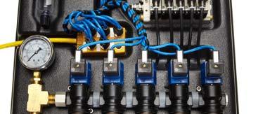
4 Illustration Aqua-Lab MD5 Air Ports Aqua-Lab BX Primary Regulator Air Regulator Air Valve M12 Block Hydra-Cannon Manifold Solenoid Valve Water Ports Water Port Air Ports Motor Starter (Dual Configuration Shown) Timer Relay Contactor Overload Current Sensor Terminal Blocks - 1 -
 or the target flow rate and the chemical dilutions chart (appendix) install the appropriate injector into each port 2.")
5 Initial Injector Setup (Based on field experience this is HFI s recommended staring point) 1. Using the recommended starting point (appendix page 10) or the target flow rate and the chemical dilutions chart (appendix) install the appropriate injector into each port 2. Connect pre-run solution lines to each Injector with the supplied coupler and push connect fitting a. Be sure to use teflon tape when connecting the injector to the coupler and push connect fitting to ensure there are no leaks b. Do not over tighten poly fittings or they may crack 3. Connect ¼ poly lines from each chemical container to the appropriate injector a. Ensure a foot valve or similar check valve/filter is installed on each line i. These must be present or metering tips may clog 4. Metering tips will need to be installed to set dilution ratio (see appendix for ratio charts to determine tip) If the spray nozzles on the arch are too small for the injector chosen, the back pressure put on the injector may cause the vacuum not to function and chemical will not be pulled. The back pressure should not exceed 66 psi. Back pressure gauges are available for purchase from HFI. (P/N ) Water will continue to flow as normal. Injector Vacuum Check (for troubleshooting injectors) 1. At the ChemFlex injector, remove the chemical feed line from the injector hose barb. 2. Attach the tubing of the vacuum gauge to the ChemFlex hose barb 3. With the pump(s) on, manually activate the chemical that is to be tested at the main car wash control cabinet. An injector that is working properly will have a reading greater than or equal to ( ) 20 in Hg 4. If injector is not functioning: a) Check metering tip for clogs (can be tested with no metering tip to ensure injector is performing) b) Try smaller injector (this will produce less flow and thus less backpressure) c) Remove a nozzle(s) at the arch, allowing water to free flow (this will reduce backpressure) 5. Repeat steps 2-4 for each chemical lane that a vacuum reading is needed for. 6. Once testing is complete, turn off the AQUA-LAB pump from the main car wash control cabinet. There is a variation of performance in the injectors that comes from slight variations in the dimensions of the parts and in assembly that are unavoidable. It is common to see the resultant vacuum range from 20 in Hg all the way up to 28. There is also variation in the through hole size on the meter tips from Dema (within their manufacturing tolerances). Using the same tip color from site to site is a good starting point. However with the potential for variation from part to part it is reasonable to still need to do some adjustments from there. Nozzle Setup (optional for maximized optimization) Using the recommended starting point (appendix) install the recommended nozzles o This may involve removing and plugging some ports o Due to the lower water usage determined by the injector of the AQUA-LAB you will need to match the flow of the application device to the injector o Setup the nozzle spray patterns to paint the car - slightly overlapping each other - 2 -

6 Triple Foam Setup (for MD5 if ordered with extra regulators) If your MD5 panel was ordered with 3 air valves and 5 air regulators or with 5 air valves and 7 air regulators the below instructions will show you how to setup your triple foam. 3 Valve / 5 Regulator MD5 Panel Your triple foam has been setup from the factory to be in port 3 Insert your triple foam manifold into position 3 with your selected injectors already inserted On the side of the panel the 3 rd, 4 th, and 5 th regulators (numbering starts at the top) will control the air to each of your triple foam colors Insert your air lines to the arch into the bulkhead fittings on the bottom of the panel. The 3 rd, 4 th, and 5 th bulkhead (counting from left to right) will be the airlines for each color. 5 Valve / 7 Regulator MD5 Panel Your triple foam has been setup from the factory to be in port 5 Insert your triple foam manifold into position 5 with your selected injectors already inserted On the side of the panel the 5 th, 6 th, and 7 th regulators (numbering starts at the top) will control the air to each of your triple foam colors Insert your air lines to the arch into the bulkhead fittings on the bottom of the panel. The 5 th, 6 th, and 7 th bulkhead fittings (counting from left to right) will be the airlines for each color. Note: Occasionally if all three regulators are pre-set too high, you may need to lower all three regulators to their lowest setting and then turn them up to the desired pressure

7 Optimizing the System Consistently achieve the desired cleaning and presentation/performance using the least amount of chemical and water Injectors vs. Metering Tips vs. Nozzles The key to optimizing the system is through trial and error. Don t be afraid to try these steps to achieve your ideal performance. What do injectors do? o Increases or decreases the amount of water in the solution What do metering tips do? o Increases or decreases the amount of chemical in the solution What do nozzles do? o Determines the pattern and backpressure of the solution Application Optimization (repeat for each application) For Example Foaming Presoak Application View Performance at Arch with Decision Maker Application too wet o Increase air o Reduce injector size (decreases water) o Increase metering tip (increases chemical) Application too dry o Decrease air o Increase injector size (increases water) o Decrease metering tip (decreases chemical) Nozzle sputters o Decrease air o Decrease nozzle(s) and/or size used on arch o Increase injector size (increases water) Too much chemical used o Decrease metering tip o Decrease metering tip and injector size (to maintain desired ratio) No chemical o Check vacuum of injector (see instructions on page 9) o Check foot valve o Check metering tip Nozzle fan pattern not filled o Reduce nozzle size o Increase injector size (increases water) Water not present at all nozzles on arch o Verify check valves are functioning o Verify nozzles are not plugged o Reduce number of nozzles o Reduce nozzle size o Increase injector size (increases water) - 4 -
8 Chemical Usage Measuring Verify titration of chemicals before proceeding 1. Setup lab scale with small bucket of chemical to be measured. 2. Put the suction line into the bucket. 3. Run the application being tested to prime the line. (All air bubbles must be removed for accuracy) 4. Record the Initial Weight from the scale. (Tarring the scale with weight on the scale can affect accuracy) 5. Run the application for 6 vehicles (or manually for the same it would be on for 6 vehicles). 6. Record the Final Weight from the scale. 7. Subtract the Initial Weight from the Final Weight to determine the weight of used product. 8. Divide this Used Weight by 6 to get a per car weight. 9. Divide the Per Car Weight in grams by the specific gravity of the chemical to determine the milliliters of chemical used per vehicle. 10. Repeat for each chemical application. Recommended Maintenance The recommended service and maintenance on the AQUA-LAB System are as follows. Monthly Check and drain air regulator Check water filter and replace as needed (if installed) Semi-Annually Check and replace injector metering tips Clean solenoid valves Check and clean Y strainer Inspect and replace chemical lines as needed Annually Replace filter in air regulator Clean water regulator Inspect motor starter for corrosion, if identified order replacement/spare parts 2 Years Inspect and replace injectors Rebuild valves Rebuild water regulator - 5 -
 steel hex closest to the plastic manifold body. 4.")
9 Valve Replacement / Cleaning Instructions 1. Start by removing the nut and washer from the top of the solenoid coil. 2. Remove the coil and set aside. 3. Unscrew and remove the valve assembly using the larger (1 1/8 ) steel hex closest to the plastic manifold body. 4. On a clean work surface disassemble the valve assembly by using a 1 deep wall socket to remove the plunger tube from the valve cage in a vertical orientation with the valve outlet pointed down. Be careful with the small components and note how it is assembled. 5. Inspect for debris that could interfere with the valves operation, paying particular attention to anything blocking the two small holes through the piston, particles imbedded in the Teflon Ring, and debris in the plunger tube or across the valve seat. If debris is found in the valve assembly it is recommended that a 100 mesh filter or sediment trap be installed prior to the AQUA-LAB. A scotch brite pad can be used to remove buildup. 6. After cleaning out any and all debris, to reassemble, first place the piston into the valve cage taking care to keep the Teflon ring in place. Do not to force it or the valve will not function. 7. Hook the piston pickup on the piston. 8. Hook the plunger on the piston pick up. 9. Make sure that the spring and spacer are installed in the back of the plunger. 10. Place the plunger tube over the plunger and tighten. 11. To check for correct assembly insert a hex key (Allen wrench) into the tip of the valve cage and actuate the valve. The piston should re-seat each time it is pressed open. (The piston only moves approximately.040.) Valve Cage Valve Seat (inside valve cage) Teflon Ring (on piston) Piston Pickup Spring Coil Plunger Tube Piston Plunger Spacer - 6 -
10 Troubleshooting Operating Manual PROBLEM POTENTIAL CAUSES SOLUTIONS Pump Operates, but delivers little or no water Pump not primed Inlet Restriction Missing 1 of 3 Phases Inadequate water supply Undersized piping Leak on the Inlet side Worn or defective pump parts Incorrect Motor rotation See priming instructions Check all in-line filters and inlet plumbing for restrictions. Check valves and backflow preventers Wire according to diagram Check pressure on inlet side of pump to be sure positive pressure is maintained Replace with larger piping Make sure connections are tight Replace worn parts or entire pump, Clean parts if required Reverse motor rotation by interchanging any two leads Pump won't start or run at full speed Excessive Noise from Pump Pump Leaks Injector is not drawing chemical - Passes Vacuum Pressure check test Injector is not drawing chemical - Fails Vacuum Pressure check test Blown fuse or circuit breaker Defective Motor Starter contactor Current Sensor set to high Thermal Overload set to low Incorrect Motor Voltage Defective motor E-Stop is depressed Pump components damaged Not Primed Pump not secured firmly Restricted Inlet Water regulator fluttering Cavitation (Sounds like marbles in pump) Worn mechanical seal Worn o-ring seals Clogged chemical feed Too much back pressure on injector Clogged injector check valve Clogged injector nozzle Defective Injector Replaced fuses or close circuit breaker Replaced motor starter contactor Verify wiring Adjust setting on thermal overload to match voltage Voltage must be within 10% of motor rated voltage Replace motor unlock E-Stop Replace worn part or entire pump Reprime pump Secure properly Clean or correct restriction Try to adjust regulator down and then back up or replace regulator Increase inlet size Replace shaft seal Replace Check chemical hose, foot valve, metering tip and hose barb for debris or clogs Perform back pressure check test outlined in Section IV if this manual. If the result is higher than 66 psi then Increase arch nozzle size or quantity, use larger tubing, or use a smaller flow injector Blow compressed air through the chemical hose barb on the injector to remove debris Remove injector and blow out any debris with compressed air If Vacuum check fails but Back Pressure is less than 66 psi, replace the injector - 7 -
11 PROBLEM POTENTIAL CAUSES SOLUTIONS System won't regulate up to 200 psi Pump not primed Follow priming instructions Debris in regulator Remove regulator and clean out debris Motor rotation incorrect Verify rotation and adjust wiring to correct Opening to many valves at once System is limited to opening up to 8 valves at once or pressure will be greatly affected by so much demand Defective Check Valve Replace check valve if broken Defective Regulator Replace Regulator Defective Pump Replace Pump Flow at arch is too low Incorrect Injector Flow Rate Replace with desired injector size Selection System pressure too low Ensure system pressure is set at 200 psi Foam Generator Plugged Ensure cleaned and clear Downstream pluming restrictive Perform Back pressure test outlined in Section IV of this manual, if over 66 psi, increase tube size and reduce elbows, turns or other restrictive plumbing No flow from injector Valve stuck open Staying open when signal is off Starter Tripping Solenoid valve malfunction Clogged Injector No water supply Debris in valve seat Incorrect Overload Setting Ensure valve is receiving the correct electrical signal and voltage Valve may be assembled incorrectly Disassemble valve and clean out debris (See valve replacement instructions) Remove injector and blow out debris with compressed air Check that the system has a supply of water Remove and clean valve (See valve replacement instructions) Verify overload setting versus settings found in specs page of this document - 8 -

12 Appendix - 9 -
13 Setup Starting Point Recommended Aqua-Lab Setup Starting Point Chemical Application Injector Range Air Nozzles Presoak KSS12 X4 CTA X4 Wrap App. Dep. Mitter App. Dep. TriFoam Colors App. Dep. Bug Blaster App. Dep. App. Dep. Under Carriage App. Dep. App. Dep. Drying Agent X8 Sealer Wax X8 Body Protectant KSS12 X6 Foamer App. Dep. Scent App. Dep App. Dep App. Dep. App. Dep. Wheel Protectant App. Dep. App. Dep

14 Chem-Flex Injector Listing Aqua-Lab Chem Flex Injector Listing Part Number # Barbs GPM

15 AQUA-LAB WARRANTY Factory Limited Hydra-Flex Inc warrants its equipment to be free from defect in material or workmanship under proper normal proper use for a period of one (1) year beginning the date of purchase. The Hydra-Flex Inc s liability shall be limited to repair or replacement of parts found to be defective within the warranty period and following Hydra-Flex Inc s inspection. Hydra-Flex Inc shall have the option requiring the return of defective material to establish the purchaser s claim. In the event of repair or replacement this limited warranty is non-cumulative. Neither labor nor transportation charges are included in this warranty. This warranty is based upon the proper care and maintenance of the warranted equipment. Warranty does not apply if the merchandise is altered or modified in any way. Warranty does not apply to any equipment which has been subject to misuse, inappropriate use of tools, including exposure to harsh chemicals, neglect, lack of maintenance, freezing, fluid hammer, accident, third party damage, fluid impurities such as sand or minerals, acts of God or acts of war. Nor does it apply to any equipment which has been repaired or altered by anyone not so authorized by Hydra-Flex Inc. All equipment must be properly installed in accordance with specified plumbing, electrical, and mechanical requirements. The warranty does not apply to normal wear and tear or routine maintenance components as described in the equipment manual. Except as expressly stated herein, Hydra-Flex Inc shall not be liable for damages of any kind in connection with the purchase, maintenance, or use of this equipment including loss of profits and all claims for consequential damages. This limited warranty is in lieu of all other warranties expressed or implied. Hydra-Flex Inc neither assumes nor authorizes any person to assume for it any other obligation or liability in connection herewith. This warranty is neither assignable nor transferable. Transportation damage claims are to be submitted to the carrier of the damaged material
BUG PREP KIT 2.0 HAND-PREP SYSTEM. User Manual REV A reva0616
 BUG PREP KIT 2.0 HAND-PREP SYSTEM User Manual REV A 4000110 reva0616 Hydra-Flex, Hydra-Flex, Inc. 2016 Inc. 2016 Page 1 TABLE OF CONTENTS Overview 3 Standard Bug Prep Kit 2.0 3 Bug Prep Retro Controller
AQUA-LAB AX, BX, TX. CHEMICAL DISPENSING SYSTEM User Manual REV A reva0717
 AQUA-LAB AX, BX, TX CHEMICAL DISPENSING SYSTEM User Manual REV A 4000133 reva0717 Hydra-Flex, Hydra-Flex, Inc. 2017 Inc. 2017 TABLE OF CONTENTS Overview 1 Features 1 Specifications 1 Installation Instructions
AQUA-LAB SD CHEMICAL DISPENSING SYSTEM. User Manual REV G revg0518
 AQUA-LAB SD CHEMICAL DISPENSING SYSTEM User Manual REV G 4000061 revg0518 Hydra-Flex, Hydra-Flex, Inc. 2018 Inc. 2017 TABLE OF CONTENTS Specifications 1 Aqua-Lab SD System Diagrams 2 Layout Drawing 4 Estimated
AQUA-LAB MD CHEMICAL DISPENSING SYSTEM. User Manual REV V revv0118
 AQUA-LAB MD CHEMICAL DISPENSING SYSTEM User Manual REV V 0000 revv08 Hydra-Flex, Hydra-Flex, Inc. 08 Inc. 08 Page TABLE OF CONTENTS Specifications Layout Drawings Booster Pump & MCU Layout Drawings Grundfos
AQUA-LAB SD GEN2 CHEMICAL DISPENSING SYSTEM. User Manual REV B revb0518
 AQUA-LAB SD GEN2 CHEMICAL DISPENSING SYSTEM User Manual REV B 4000122 revb0518 Hydra-Flex, Hydra-Flex, Inc. 2018 Inc. 2018 Page 1 TABLE OF CONTENTS Specifications 3 Layout Drawing 4 Panel Diagram 5 Motor
AQUA-LAB HD/XD CHEMICAL DISPENSING SYSTEM. User Manual REV L revl1018
 AQUA-LAB HD/XD CHEMICAL DISPENSING SYSTEM User Manual REV L 000087 revl08 Hydra-Flex, Hydra-Flex, Inc. 08 Inc. 08 Page TABLE OF CONTENTS Specifications Layout Drawing Panel Diagram Estimated Installation
AQUA-LAB HD/XD CHEMICAL DISPENSING SYSTEM. User Manual REV F revf0917
 AQUA-LAB HD/XD CHEMICAL DISPENSING SYSTEM User Manual REV F 4000087 revf0917 Hydra-Flex, Hydra-Flex, Inc. 2017 Inc. 2017 Page 1 TABLE OF CONTENTS Specifications 3 Layout Drawing 4 Panel Diagram 5 Estimated
AQUA-LAB MD/XD GEN2 & HD
 AQUA-LAB MD/XD GEN & HD CHEMICAL DISPENSING SYSTEM User Manual REV D 0009 revd08 Hydra-Flex, Hydra-Flex, Inc. 08 Inc. 08 Page TABLE OF CONTENTS Specifications Layout Drawing Estimated Installation Timeline
AQUA-LAB MD/XD GEN2 & HD
 AQUA-LAB MD/XD GEN2 & HD CHEMICAL DISPENSING SYSTEM User Manual REV B 4000129 revb1117 Hydra-Flex, Hydra-Flex, Inc. 2017 Inc. 2017 Page 1 TABLE OF CONTENTS Specifications 3 Layout Drawing 4 Estimated Installation
Air Compressor. Owner s Manual. Sonny's Enterprises, Inc Hiatus Road Tamarac, Florida v1
 Owner s Manual Sonny's Enterprises, Inc. 5605 Hiatus Road Tamarac, Florida 33321 16v1 *Table of Contents* WARNING *SAFETY REQUIREMENTS* WARNING... 3 *INTRODUCTION*... 5 Product Specifications... 6 Optional
HALLMARK INDUSTRIES INC
 Performance Part No. HP. CONVERTIBLE JET PUMP USER S MANUAL GPH of Water @ Total Discharge Pressure of 40 psi Max. Pressure Max suction (shallow well) Max Suction (deep well) Max GPM (@0 head) Max Discharge
Model AM2 M40 Panel Installation, Operation, and Maintenance Manual
 Model AM2 M40 Panel Installation, Operation, and Maintenance Manual RECEIVING AND INSPECTION Upon receiving unit, check for any interior and exterior damage, and if found, report it immediately to the
StormPro BA Series Sump Pump
 Page 1 of 8 Marks & Meanings DANGER: Keep the pump equipment out of the reach of children! Warns that the failure to follow the directions given could cause serious risk to individuals or objects. WARNING:
PPM EO-100 TM. Operation Manual
 PPM EO-100 TM Open Loop Electric Prewet Power Module Operation Manual Rev A Page 1 2/23/2010 Copyright 2008 by Cirus Controls, LLC. All Rights Reserved. No part of this material may be reproduced in any
DEMA 258BD-200C and 258BT-200C DRAIN MASTER Jr. INSTALLATION INSTRUCTION SHEET
 I-736 Pg. 1 of 10 Summary The 258BD-200C Drain Master is designed to feed chemicals into drains and grease traps to break up grease, detergent buildup and eliminate odors. The 258BT-200C Trash Master is
Cyclone Trash Separator
 Owner's Manual Sonny's Enterprises, Inc. 5605 Hiatus Road Tamarac, Florida 33321 16v1 *Table of Contents* WARNING *SAFETY REQUIREMENTS* WARNING... 3 *INTRODUCTION*... 5 Product Specifications... 6 *INSTALLATION*...
INSTRUCTIONS. Fc. -1,<" SERIES ST-261 REGULATING UNLOADER VALVE
 INSTRUCTIONS Fc. -1,
SUNC1200 / ITEM #40882 SUBMERSIBLE UTILITY PUMP OPERATIONS MANUAL
 SUNC1200 / ITEM #40882 SUBMERSIBLE UTILITY PUMP OPERATIONS MANUAL WWW.SUNRUNNERPOOL.COM Performance Model HP GPH of Water @ Total Feet Of Lift 0 ft. 5 ft. 10 ft. 15 ft. 20 ft. 25 ft. Max. Lift SUNC1200
Intended Use: Explanation of Signal Word Consequences
 SAFETY INFORMATION & INSTRUCTION MANUAL Please read, understand, and follow all safety information contained in these instructions prior to the use of this device. Retain these instructions for future
Read this entire manual before operation begins.
 Read this entire manual before operation begins. Record below the following information which is located on the serial number data plate. Serial No. Model No. Date of Installation Contents Specifications.............
ESE Series Cast Iron Sewage Pumps
 Owner s Manual ESE Series Cast Iron Sewage Pumps TABLE OF CONTENTS General Safety.................... 2 Specifications..................... 3 Installation.................... 4 & 5 Troubleshooting...................
36-1 DP PLEASE READ BEFORE USING THIS EQUIPMENT
 36-1 DP PLEASE READ BEFORE USING THIS EQUIPMENT DP 36-1 Assembly Instructions PLEASE READ INSTRUCTIONS COMPLETELY BEFORE STARTING We thank you for purchasing the DP-36 pressure system. This system has
Agxcel GX12i Chemical Injection System
 Agxcel GX12i Chemical Injection System Table of Contents System Contents... 3 Specifications... 4 Safety Precautions and Tips... 5 Operations... 6 Installation... 7 Maintenance... 8-9 Troubleshooting...
BLAST-TEC PRO. Rotating Turbo Nozzles. Optimization & Troubleshooting Guide REV C revc0118
 BLAST-TEC PRO Rotating Turbo Nozzles Optimization & Troubleshooting Guide REV C 4000002 revc08 Hydra-Flex, Hydra-Flex, Inc. 208 Inc. 208 TABLE OF CONTENTS Product Overview Product Line Description Specifications
Top Brush Auto Retract (Zelio PLC)
") () Owner s Manual Sonny's Enterprises, Inc. 5605 Hiatus Road Tamarac, Florida 33321 16v1 *Table of Contents* Equipment Program - Manuals WARNING *SAFETY REQUIREMENTS* WARNING... 3 *INTRODUCTION*... 5 Product
() Owner s Manual Sonny's Enterprises, Inc. 5605 Hiatus Road Tamarac, Florida 33321 16v1 *Table of Contents* Equipment Program - Manuals WARNING *SAFETY REQUIREMENTS* WARNING... 3 *INTRODUCTION*... 5 Product
LBT-3 WITH 300 CFM RECLAIM MANUAL NUMBER: 506 TABLE OF CONTENTS
 LITTLE BLASTER LITTLE BLASTER LBT-3 WITH 300 CFM RECLAIM MANUAL NUMBER: 506 TABLE OF CONTENTS PAGE FIGURE 1 - SET-UP INSTRUCTIONS 1 - OPERATING INSTRUCTIONS 1 - GENERAL MAINTENANCE 2 1 STANDARD CABINET
PowerFLO 7800 Series 12 Volt DC Motor-Driven Diaphragm Pumps
 Installation Operation Repair Parts PowerFLO 7800 Series 12 Volt DC Motor-Driven Diaphragm Pumps Specifications Motor Type: 12 VDC, permanent magnet, totally enclosed, non-ventilated Leads: 14 AWG, 12
Aqua Ultraviolet Sunami Series Pumps 1/3HP, 3/4HP, 3HP, 4HP, 5HP
 TM 42371 Avenida Alvarado Temecula, CA 92590 TOLL FREE (800) 454-2725 TEL (951) 296-3480 FAX (951) 296-3490 www.aquauv.com Aqua Ultraviolet Sunami Series Pumps 1/3HP, 3/4HP, 3HP, 4HP, 5HP Sunami Warranty
PEDESTAL SUMP PUMP. MODEL # Español p. 11. Zoeller is a registered trademark of Zoeller Co. All Rights Reserved.
 PEDESTAL SUMP PUMP Zoeller is a registered trademark of Zoeller Co. All Rights Reserved. MODEL #1084-0001 Español p. 11 ATTACH YOUR RECEIPT HERE Serial Number Purchase Date Questions, problems, missing
23200 Navigator Dilution Control System 4 Button Model (NAV 4)
") 23200 Navigator Dilution Control System 4 Button Model (NAV 4) Overview The NAV 4 Chemical Dilution Control System accurately dilutes cleaning chemicals from cleaning concentrate product. It is a closed
23200 Navigator Dilution Control System 4 Button Model (NAV 4) Overview The NAV 4 Chemical Dilution Control System accurately dilutes cleaning chemicals from cleaning concentrate product. It is a closed
Atlas PV-9WP Addendum
 Atlas PV-9WP Addendum 9,000 lb. Capacity Two-Post Overhead Lift The Atlas PV-9WP above ground hoist is 6 inches wider than the Atlas PV-9P, giving it an overall width of 141 (11 9 ) and a drive thru width
SUBMERSIBLE SUMP PUMPS
 SUBMERSIBLE SUMP PUMPS Zoeller is a registered trademark of Zoeller Co. All Rights Reserved. MODELS #1073-0001, 1075-0001 Español p. 9 ATTACH YOUR RECEIPT HERE Serial Number Purchase Date Questions, problems,
PowerFLO 5800/5900 Series
 PowerFLO 5800/5900 Series 5830/5930: 3.0 GPM 5836/5936: 3.6 GPM Inches (mm) Bypass Models Demand Models Switch 1.87 (47.5) 7.58 (192.5) 7.58 (192.5) 9.08 (230.6) 5840/5940: 4.0 GPM 5850/5950: 5.0 GPM Inches
SUBMERSIBLE SUMP PUMPS
 SUBMERSIBLE SUMP PUMPS Zoeller is a registered trademark of Zoeller Co. All Rights Reserved. MODEL #1099-0001 Español p. 11 ATTACH YOUR RECEIPT HERE Serial Number Purchase Date Questions, problems, missing
SPLASH-N-DASH. Coleman Hanna Carwash Systems. World Class Manufacturing in Car Wash Equipment. Splash-N-Dash Installation/Operation Manual
 Manual SPLASH-N-DASH Page 1 of 25 Rev. 2 6/9/10 Manual Table of Contents INSTALLATION PROCEDURES...3 SEQUENCE OF OPERATION...14 TROUBLESHOOTING GUIDE...17 TURTLE WAX HYPER-CONCENTRATE CHEMICAL USAGE...19
1-BUTTON DISPENSER INSTALLATION INSTRUCTIONS
 R 1-BUTTON DISPENSER INSTALLATION INSTRUCTIONS Model: #91162-00 The Green Earth II 1-button dispenser allows you to dispense one product for mop buckets and automatic scrubbers. The modular design lets
Part #82064 Add-A-Stage EFI Nitrous System
 1 INSTRUCTIONS Part #82064 Add-A-Stage EFI Nitrous System Thank you for choosing products; we are proud to be your manufacturer of choice. Please read this instruction sheet carefully before beginning
ProFlo FatBoy
 The Standard For Professional Grade Diaphragm Pumps. ProFlo 3300 5500 FatBoy Operational and Installation Guidelines, Repair & Parts Contents 3300 5500 Fatboy Operational and Installation Guidelines...2
TABLE 1-1 GPM FLOW RATE PROPORTIONER, 1/4 I.D. TUBING Injection Rates For Viscosities Shown Metering Tip Color
 Blend Safe II Dispensing System is a modular, locking dispensing system that allows user to dispense chemicals safely, control dispenser inventory and has the flexibility in the field to meet changing
SINGLE-STAGE INJECTOR MODELS 200-3C, 200C, 201C, 202C, 203C, 204C, 206C, 208C
 D E M A SINGLE-STAGE MODELS SINGLE-STAGE MODELS 1. PARTS A. Injector B. Backup washer (Models 204C & smaller). C. Ceramic Weight. D. Tubing 8 long w/ foot strainer. E. Three brass nozzle bushings Metering
MACHINES / RECLAIMS WITH DUST BAG
 WARNING SET-UP INSTRUCTIONS MACHINES / RECLAIMS WITH DUST BAG *** READ BEFORE OPERATING EQUIPMENT *** 1. Remove plastic from machine. 2. Remove lag bolts from each of the four legs, then remove machine
7 Maintenance Do not allow the sludge accumulation in the tank to exceed a 1 depth. Otherwise, the sludge build-up could damage the heating element(s)
") 7 Maintenance Do not allow the sludge accumulation in the tank to exceed a 1 depth. Otherwise, the sludge build-up could damage the heating element(s) and pump. Depending on the application, some businesses
7 Maintenance Do not allow the sludge accumulation in the tank to exceed a 1 depth. Otherwise, the sludge build-up could damage the heating element(s) and pump. Depending on the application, some businesses
Model Series. PumpAgents.com - buy pumps and parts online ELECTRIC BILGE PUMPS. Model Series FEATURES SPECIFICATIONS STANDARD MODELS
 PumpAgents.com - Click here for Pricing/Ordering Model 36600-Series ELECTRIC BILGE PUMPS FEATURES Self-Priming Diaphragm Design Allows Dry Running Quiet Operation Built-in Hydraulic Pulsation Dampener
Read this entire manual before operation begins.
 Read this entire manual before operation begins. Record below the following information which is located on the serial number data plate. Serial No. Model No. Date of Installation Contents Specifications.............
NECO Pumping Systems
 INSTALLATION OPERATION & MAINTENANCE INSTRUCTIONS For Your NECO Pumping Systems PACKAGED CIRCULATING SYSTEM THIS COMPLETELY ASSEMBLED, TESTED, PACKAGED CIRCULATING SYSTEM IS OF THE HIGHEST QUALITY AND
TPHK Series Immersible Pump
 TPHK Series Immersible Pump Instruction Manual ISO 9001 Certified Walrus America Inc 234867 EC Declaration of Conformity Manufacturer: Walrus Pump Co., Ltd. Address: No. 83-14, Dapiantou, Sanjhih Township,
DEMA DILUTION-AT-HAND EXTREME 800 Series Chemical Dispensers
 DEMA DILUTION-AT-HAND EXTREME 800 Series Chemical Dispensers Overview The DILUTION-AT-HAND EXTREME chemical dispenser series combines the proven technology of the DEMA DILUTION-AT-HAND with a new look
MODEL 1100 TURBINE FLOW METER
 MODEL 1100 TURBINE FLOW METER INSTALLATION & INSTRUCTION MANUAL 8635 Washington Ave. Racine, Wisconsin 53406 Phone: 800.433.5263 Fax: 800.245.3569 www.hedland.com 2 OPERATIONAL START-UP Fluid entering
CRD600 Automatic Fitting Inserter
 CRD600 Automatic Fitting Inserter OPERATIONS MANUAL VERSION 2.3 LAST EDITED 12.07.2018 cleanroomdevices.com 1 Table of Contents Title Page.. 1 Table of Contents. 2 1.0 General Product & Safety Information...3
CRD610 Automatic Fitting Inserter
 CRD610 Automatic Fitting Inserter OPERATIONS MANUAL VERSION 1.2 LAST EDITED 12.12.2018 cleanroomdevices.com 1 Table of Contents Title Page. 1 Table of Contents...2 1.0 General Product & Safety Information....3
SOLUTION STATION Instruction Manual
 SOLUTION STATION Instruction Manual WAXIE Sanitary Supply 9353 WAXIE Way San Diego, CA 92123 Phone: 800.995.4466 www.waxie.com TABLE OF CONTENTS Unpacking Instructions Disclaimer..... Warranty... Introduction...
TPAK Series COOLANT PUMP
 TPAK Series COOLANT PUMP Instruction Manual ISO 9001 Certified WALRUS PUMP CO., LTD. EC Declaration of Conformity Manufacturer: Walrus Pump Co., Ltd. Address: No.83-14, Dapiantou, Sanzhi Dist., New Taipei
LIQUIDYNAMICS Light Viscosity Bulk Transfer Cart
 This manual contains important warnings and information. READ AND KEEP FOR REFERENCE. LIQUIDYNAMICS Light Viscosity Bulk Transfer Cart Instruction & Parts Manual This Manual Covers P/N 33271 P/N 33271
Self Cleaning Hood System Installation, Operation, and Maintenance Manual
 Self Cleaning Hood System Installation, Operation, and Maintenance Manual RECEIVING AND INSPECTION Upon receiving unit, check for any interior and exterior damage, and if found, report it immediately to
PeroxiDraw Dispenser
 The PeroxiDraw Dispensing System is a locking dispensing system that allows the user to dispense Green Earth Peroxide Cleaner for up to six different dilutions and applications safely and effectively.
STOP CITY PRESSURE BOOSTER PUMP INSTRUCTION MANUAL
 CITY PRESSURE BOOSTER PUMP INSTRUCTION MANUAL MODEL #VP05, VP10 C US NSF/ANSI 372 255405 For loose, missing or damaged parts, or if the unit does not seem to be operating properly, please call before returning
DEMA BLEND CENTER MODELS: 633GAP INSTALLATION INSTRUCTIONS
 The 633GAP Series Blend Center modular design lets you easily couple together any number of stations to create a system that meets your specific needs. Mix and match both high and low flow units for filling
Medi-Flow. Model M101 & M101D Medicator Instructions GETTING TECHNICAL ASSISTANCE
 UNPACKING Please open and inspect your package upon receipt. Your package was packed with great care and all the necessary packing materials to arrive to you undamaged. If you do find an item that is broken
OWNER S MANUAL SUBMERSIBLE UTILITY PUMP
 Model 51101-0 OWNER S MANUAL SUBMERSIBLE UTILITY PUMP Questions, problems, missing parts? Before returning to the store call AQUAPRO Customer Service 8 a.m. - 5 p.m., EST, Monday-Friday 1-844-242-2475
IMPORTANT OPERATING CONDITIONS. Failure to comply with any of these conditions invalidates the warranty. STANDARD CONFIGURATIONS
 X-SERIES TRIPLEX CERAMIC PLUNGER PUMPS OPERATING MANUAL MODELS X8 X10 X20 IMPORTANT OPERATING CONDITIONS Failure to comply with any of these conditions invalidates the warranty. Lubrication - Prior to
Troubleshooting. This section outlines procedures for troubleshooting problems with the operation of the system:
 Troubleshooting This section outlines procedures for troubleshooting problems with the operation of the system: 4.1 System Error Messages... 4-2 4.2 Prep Station Troubleshooting... 4-6 4.2.1 Adapter Not
OWNER S MANUAL REMOTE CONTROL, DUAL HEAD FOGGING SYSTEMS
 OWNER S MANUAL Sentinel II 5500 REMOTE CONTROL, DUAL HEAD FOGGING SYSTEMS Read all instructions carefully before starting the installation. Save this manual for future use. 2 OWNER S MANUAL SAFETY Always
Read this entire manual before operation begins.
 Read this entire manual before operation begins. Record below the following information which is located on the serial number data plate. Serial No. Model No. Date of Installation Contents Specifications.............
SOLAR ELECTRIC SUBMERSIBLE PUMP D.C. POWERED OWNERS MANUAL
 SOLAR ELECTRIC SUBMERSIBLE PUMP D.C. POWERED OWNERS MANUAL INSTALLATION AND OPERATION SWP SERIES MANUFACTURED BY: Aquatec International, Inc. 17422 Pullman Street Irvine, Ca. 92614 United States of America
CLEAN ROOM DEVICES, LLC "WHERE TUBING AND FITTINGS COME TOGETHER"
 CLEAN ROOM DEVICES, LLC "WHERE TUBING AND FITTINGS COME TOGETHER" CRD600 Automatic Fitting Inserter OPERATIONS MANUAL VERSION 2.1 LAST EDITED 7.25.14 DOCUMENT NUMBER 001 cleanroomdevices.com 1 Table of
Read this entire manual before operation begins.
 Read this entire manual before operation begins. Record below the following information which is located on the serial number data plate. Serial No. Model No. Date of Installation Contents Specifications.............
OWNER S MANUAL SELF-PRIMING PORTABLE UTILITY PUMP
 Model 54011-0 OWNER S MANUAL SELF-PRIMING PORTABLE UTILITY PUMP Questions, problems, missing parts? Before returning to the store call AQUAPRO Customer Service 8 a.m. - 5 p.m., EST, Monday-Friday 1-844-242-2475
Value Super Filter Max Installation Manual
 Value Super Filter Max Installation Manual Barrie, Ontario, Canada, L4N 4Y8 www.excaliburwater.com EXCALIBUR VALUE SUPER FILTER MAX INSTALLATION MANUAL INSTALLATION PROCEDURES: The Value Super Filter Max
PARTS AND INSTALLATION MANUAL
 PSP-3240 POLYPROPYLENE SELF-PRIMING 2 CENTRIFUGAL PUMP PARTS AND INSTALLATION MANUAL PSP-3240 Shown with GX-160 Honda CDS-JOHN BLUE COMPANY DIVISION OF ADVANCED SYSTEMS TECHNOLOGY, INC. 165 Electronics
Model 1100 Turbine Flow Meter
 Model 1100 Turbine Flow Meter INSTALLATION & INSTRUCTION MANUAL 8635 Washington Avenue Racine, Wisconsin 53406 Tel: 800-433-5263 or 262-639-6770 Fax: 800-245-3569 or 262-639-2267 www.hedland.com TABLE
Read this entire manual before operation begins.
 Read this entire manual before operation begins. Record below the following information which is located on the serial number data plate. Serial No. Model No. Date of Installation Contents Specifications.............
665 Series Dispenser. Metering tip kit
 665 Series Dispenser Metering tip kit Box Contains Mounting hardware, template & key set Instruction sheet 665 series dispenser 4 SafeLink cap assemblies OR Bulk tubing, 4 ceramic weights and foot valves
STAR STOP SHALLOW WELL JET PUMP
 SHALLOW WELL JET PUMP MODEL SJ0S / HP STAR starwatersystems.com STOP Questions, problems, missing parts? Before returning to your retailer, call our customer service department at -800-7-0, 7:0 a.m. -
Read this entire manual before operation begins.
 Read this entire manual before operation begins. Record below the following information which is located on the serial number data plate. Serial No. Model No. Date of Installation Contents Specifications.............
MODEL 900 IMPELLER-TYPE FLOW METER
 MODEL 900 IMPELLER-TYPE FLOW METER - For Water Applications - INSTALLATION & INSTRUCTION MANUAL 8635 Washington Avenue Racine, Wisconsin 53406 Toll Free: 800.235.1638 Phone: 262.639.6770 Fax: 262.417.1155
SOLAR ELECTRIC SUBMERSIBLE PUMP D.C. POWERED OWNERS MANUAL
 SOLAR ELECTRIC SUBMERSIBLE PUMP D.C. POWERED OWNERS MANUAL INSTALLATION AND OPERATION SWP SERIES MANUFACTURED BY: Aquatec International, inc. 17422 Pullman Street Irvine, Ca. 92614 United States of America
CLEAN ROOM DEVICES, LLC "WHERE TUBING AND FITTINGS COME TOGETHER"
 CLEAN ROOM DEVICES, LLC "WHERE TUBING AND FITTINGS COME TOGETHER" CRD600AF Automatic Fitting Inserter With Auto Feed OPERATIONS MANUAL (Shown with optional alcohol dispenser) 1 VERSION 1.1 LAST EDITED
INSTALLATION INSTRUCTIONS
 Safety Notices... 1... 3 Specifications... 3 General... 3 Electrical... 3 Hydraulic Connections... 3 Components... 4 Assembly... 4 Implement Installation... 7 Hydraulic Connections... 9 Closed-Center Hydraulics...
SUNC3000 / Item #40885
 SUNC3000 / Item #40885 AUTOMATIC POOL COVER PUMP OPERATIONS MANUAL WWW.SUNRUNNERPOOL.COM 1 . Performance GPH of Water @ Total Feet Of Lift MODEL HP Max. Lift 0 ft. 5 ft. 10 ft. 15 ft. 20 ft. SUNC3000 1/3
SEWAGE PUMP MODEL # Zoeller is a registered trademark of Zoeller Co. All Rights Reserved. Español p. 14
 SEWAGE PUMP Zoeller is a registered trademark of Zoeller Co. All Rights Reserved. MODEL #1261-0001 Español p. 14 ATTACH YOUR RECEIPT HERE Serial Number Purchase Date Questions, problems, missing parts?
Instruction Sheet. 1/2 HP Portable Electric Pumps SAFETY FIRST. L2062 Rev. F 02/ IMPORTANT RECEIVING INSTRUCTIONS 2.
 Instruction Sheet 1/2 HP Portable Electric Pumps L2062 Rev. F 02/12 Index: English:...................................... 1-7 Français:.................................... 8-14 Deutsch:...................................
DEMA MODELS 606T INSTALLATION INSTRUCTIONS
 I. PARTS: A. Select-O-Spray Assembly B. 2 Pcs. Foot Strainers & 1/4" ID Tubing C. 4 Pcs. Mounting Screws & Anchors D. 1 Pc. 100-15K Metering Tip Kit TABLE 1 Hose I.D. 3/8" 1/2" 5/8" Max. Length 15 ft.
Owner s Manual Nitrate Series Salt Based Filter System
 Owner s Manual Nitrate Series Salt Based Filter System Page 2 Copyright 2012 Enviro Water Solutions Inc. All rights reserved. All information contained herein is the property of Pelican Water Systems.
Operator s Safety and Service Manual
 Operator s Safety and Service Manual Cordless Sprayer Model: H100AC ALL CHEMICALS SMK Industries, Inc. 12839 Carpenter Trail Carlisle, IA 50047 Phone: 515-202-0052 Copyright 2014, SMK Industries Inc Email:john@smksprayers.comWeb:
PENBERTHY MODELS GL AND GH GAS OPERATED JET PUMPS INSTALLATION, OPERATION AND MAINTENANCE INSTRUCTIONS
 Before installation, these instructions must be read carefully and understood. PRODUCT WARRANTY Emerson warrants its Penberthy products as designed and manufactured to be free of defects in the material
Lead-free Pneumatic Metering Valve Assemblies (Plastic Bodied) WILLOUGHBY Industries, Inc WEST 78TH STREET / INDIANAPOLIS, IN 46268
 WILLOUGHBY Industries, Inc WEST 78TH STREET / INDIANAPOLIS, IN 46268") WILLOUGHBY LEAD-FREE VALVE ASSEMBLIES INSTALLATION AND OPERATION MANUAL MODELS: PML and PML Lead-free Pneumatic Metering Valve Assemblies (Plastic Bodied) TABLE OF CONTENTS PRE-INSTALLATION INFORMATION...
WILLOUGHBY LEAD-FREE VALVE ASSEMBLIES INSTALLATION AND OPERATION MANUAL MODELS: PML and PML Lead-free Pneumatic Metering Valve Assemblies (Plastic Bodied) TABLE OF CONTENTS PRE-INSTALLATION INFORMATION...
MULTIPOSITION AIR CYLINDER
 MULTIPOSITION AIR CYLINDER CAST ALUMINUM FOUR-POSITION - ALL AIR SERVICE INFORMATION MOUNTING! Devices should be mounted and positioned in such a manner that they cannot be accidentally operated. INSTALLATION
PRE-PLUMBED SEWAGE SYSTEM
 PRE-PLUMBED SEWAGE SYSTEM Zoeller is a registered trademark of Zoeller Co. All Rights Reserved. MODEL #1910-0009 Español p. 13 ATTACH YOUR RECEIPT HERE Serial Number Purchase Date Questions, problems,
0.7 m 3 /h - 3 GPM D 07 RE 125 D 07 RE 5. owner s manual
 0.7 m 3 /h - 3 GPM D 07 RE 125 D 07 RE 5 owner s manual GB You have just become the owner of one of the latest in the line of DOSATRON proportional dosing pumps and we congratulate you on your choice.
Model F822 thru F834 Mulsifyre Directional Spray Nozzles, Open, High Velocity General Description
 Technical Services: Tel: () 31-931 / Fax: () 791-55 Model F thru F3 Mulsifyre Directional Spray Nozzles, Open, High Velocity General Description The Mulsifyre Nozzles are open (nonautomatic) nozzles and
AGXCEL GX12i CHEMICAL INJECTOR 2% INJECTOR UNIT - PN# % INJECTOR UNIT - PN# E 6TH ST KEARNEY NE
 AGXCEL GX12i CHEMICAL INJECTOR 2% INJECTOR UNIT - PN#20202 5% INJECTOR UNIT - PN#20556 116 E 6TH ST KEARNEY NE 68847 877.218.1981 #1 Table of Contents System Contents... 3 3 Specifications... 4 4 and Tips...
Reference Manual FM-200 Series
 Flush Manifold A/P FOR LIQUID LAUNDRY SUPPLY SYSTEMS Reference Manual FM-200 Series Copyright 2004 Nova Controls, Inc. P/N 20-07941-00 Rev. C i P/N 20-07941-00 Rev. C ii P/N 20-07941-00 Rev. C 1 Description
Installation & Operator s Manual
 Installation & Operator s Manual LS7 Liquid Spray System for SCH Style Spreaders Installation Instructions 1. Position and weld Enclosure Bracket (#3028485) and Support (#3014077) to spreader as shown
SHALLOW WELL JET PUMP
 SHALLOW WELL JET PUMP MODEL FJ05S 1/2 HP flintandwalling.com ATTACH YOUR RECEIPT HERE Serial Number Purchase Date 1 FW1642 B TABLE OF CONTENTS Product Specifications...2 Safety Information...2 Package
Model 6518FR. NOTE TO INSTALLER: Please leave this information with the Maintenance Department. LIMITED WARRANTY
 INSTALLATION, OPERATION & MAINTENANCE INSTRUCTIONS 1455 Kleppe Lane Sparks, NV 89431-6467 (775) 359-4712 Fax (775) 359-7424 E-mail: haws@hawsco.com website: www.hawsco.com Model 6518FR No. 2077777(21)
MEX (55) QRO (442) Web Controls
 QRO (442) Web Controls") Web Controls SINGLE AND DUAL ROTOR TENSION CONTROL BRAKES MODELS:,,,, AND INSTALLATION, OPERATION, AND MAINTENANCE INSTRUCTIONS Read this manual carefully, making full use of its explanations and instructions.
Web Controls SINGLE AND DUAL ROTOR TENSION CONTROL BRAKES MODELS:,,,, AND INSTALLATION, OPERATION, AND MAINTENANCE INSTRUCTIONS Read this manual carefully, making full use of its explanations and instructions.
DEMA BLEND CENTER MODEL 681GAP-3 INSTALLATION INSTRUCTIONS
 1. PARTS CHECKLIST: A. Blend Center Assembly B. Vinyl Supply Tubing with Foot Valve Assembly C. Ceramic Weight D. Vinyl Outlet Tubing E. Screw and Anchor Kit F. Label Card G. Metering Tip Kit 2. INSTALLATION:
StormPro BCV400 Sewage Ejector Pump
 Page 1 of 8 Marks & Meanings DANGER: Keep the pump equipment out of the reach of children! Warns that the failure to follow the directions given could cause serious risk to individuals or objects. WARNING:
Read this entire manual before operation begins.
 Rev. 12/12/2017 Read this entire manual before operation begins. Record below the following information which is located on the serial number data plate. Serial No. Model No. Date of Installation Contents
ARAG Modular Electric Valve Operating Instructions and Parts Manual
 ARAG Modular Electric Valve Operating Instructions and Parts Manual Description Form L-1479 (11/12) California Proposition 65 Warning -- This product and related accessories contain chemicals known to