Blohm + Voss Pipe Handling Equipment ABVC-200 Sliptype Elevator Technical Documentation Original Instructions
|
|
|
- Ashlyn Cora Ellis
- 5 years ago
- Views:
Transcription
1 Blohm + Voss Pipe Handling Equipment ABVC-200 Sliptype Elevator Technical Documentation Original Instructions Blohm + Voss Oil Tools Manual PN Y-D Rev 003, February
2 GENERAL INFORMATION Warnings and Note WARNING: A warning indicates a definite risk of equipment damage or danger to personnel. Failure to observe and follow proper procedures could result in serious or fatal injury to personnel, significant property loss, or significant equipment damage. NOTE: A note indicates that additional information is provided about the current topics. WARNING: This technical documentation contains instructions on safety, installation, operation and maintenance for the Blohm + Voss Oil Tools tool. It must be studied before working with the tool. Improper / Unsafe Use The tool must only be used for the designated purpose. When using the tool, the rated load must never be exceeded. Intended use of this manual This manual is intended for use by field service, engineering, installation, operation, and repair personnel. Every effort has been made to ensure the accuracy of the information contained herein. Blohm + Voss Oil Tools, will not be held liable for errors in this material, or for consequences arising from misuse of this material. Anyone using service procedures or tools, whether or not recommended by Blohm + Voss Oil Tools, must be thoroughly satisfied that neither personal safety nor equipment safety will be jeopardized. Intellectual property All rights retained. No part of this document may be reproduced in any form (print, photocopy, microfilm or any other procedure) or be processed using an electronic system without written approval of Blohm + Voss Oil Tools. All information contained in this manual is based upon the latest product information available at any time of printing. Dependent on ongoing technical improvements (ISO 9001) Blohm + Voss Oil Tools reserves the right to change the design and specifications without announcement. The values specified in this manual represent the nominal values of a unit produced in series. Slight deviations in the case of the individual devices are possible. NOTE: In the event of problems that cannot be solved with the aid of this manual, please contact one of the addresses listed below. CE Marking The tool complies with the Machinery Directive 98/37/EC and 2006/42/EC For machines containing any hydraulic or pneumatic powered parts, the Directive 94/9/EC Equipment and protective systems in potentially explosive atmospheres applies. The marking is as follows: CE Ex II 2G T5 (hydraulic tools) or CE Ex II 2G T6 (pneumatic tools). Limited Warranty The warranty provided will be void if the tool is either: 1. Repaired or serviced by a service facility which was not authorised by Blohm + Voss Oil Tools. 2. Replacement parts not manufactured by Blohm+Voss Oil Tools are used. 3. Modifications were made to the tool which were not approved by Blohm+Voss Oil Tools. Manufacturer & Agents World wide Blohm + Voss Oil Tools Hermann-Blohm-Straße Hamburg Germany Phone: / /1162 Fax: / oiltools@blohmvoss.com Blohm + Voss Oil Tools, LLC 7670 Woodway, Suite 266 Houston, Texas United States of America Phone: Fax: bvot@blohmvoss.com Premier Sea & Land Pte. Ltd. 1, Scotts Road #19-12 Shaw Centre Singapore Republic of Singapore Phone: Fax: enquiries@mtqpremier.com.sg 2


3 General safety issues Safety issues elevator WARNING: One should avoid creating ignition sources, like heat, as a result of the use of the tool with other tools or equipment. WARNING: Do not use the tool for any other purpose than WARNING: It is not allowed to use any components which are of "non-b+v" origine, or use "non-oem" parts which are not approved by B+V. It will void any warranty and may effect the correct functioning of the tool and it's safety features. WARNING: Do never unlatch/ open the tool while a pipe is suspended in the tool; the pipe will be lost! WARNING: While using the elevator, always make sure the door is completely closed Warning sign PN General warning given in this document within it`s specification. WARNING: Failure to conduct routine maintenance could result in equipment damage or injury to personnel. WARNING: Wear personal protection equipment while working with the equipment. WARNING: If any safety elements (like safety ropes, safety sheets, plates or washers) were disassembled due to maintenance work, do NOT WARNING: The company operating the tool is responsible for evaluating safe and proper use of the tool in a hazard analysis. WARNING: The operating company is obligated to issue working instructions for safe use and supervise observance of these working instructions. WARNING: Every Employee, which operates, services, inspects or otherwise involved with the use of the tool in other with the latch/latch lock fully engaged and if applicable the verification pin properly installed. WARNING: Pay special Attention to the verification pin (if applicable), latch and latch lock for any signs of wear, bending or damage at any time. in case parts are damaged or bent, replace immediatelly by new, original parts. Safety issues automatic elevators Warning sign PN Pay attention: Apply grease at least once a day. re-use them. Always replace them with new safety elements. WARNING: All warning plates, signs and labels attached to the equipment must be observed. areas has to ensure, that these actions are done by trained and by an Blohm + Voss Oil Tools authorized personnel, and should complete regular courses of training, to ensure WARNING: Ensure the connectors are from a male and female type to prevent faulty connections. Warning sign PN Danger: Do not touch. The warning plates, signs and labels must be present on the tool. Do not remove the labels. proper use as well as safe operation, correct maintainance and inspection. If they are missing, replacing is mandatory. WARNING: If necessary, a reasonable, additional WARNING: Any modification to the tool carried out without the approval of Blohm + Voss Oil Tools will void any warranty. supervisor should be appointed during operation. WARNING: Stay away from the tool during operation. In case Warning sign PN Pay attention: Do not place your hands between moving parts. WARNING: Using the tool with damaged or worn parts can create serious incidents. it is remote operated it may make movements without warning. Warning sign PN Pay attention: Risk of crushing. 3


4 Warning signs. On the following pages warning signs and their relative positions are shown. Warning sign PN Warning sign Danger PN Warning sign Automatic PN Warning sign Warning PN
5 EC-DECLARATION OF CONFORMITY We, Blohm + Voss Oil Tools Hermann-Blohm-Strasse Hamburg Phone:+49(0) Fax:+49(0) declare that the product ABVC Sliptype Elevator which is the subject of this declaration, is in conformity with the following standard(s) or normative documents 98/37/EC: Machinery Directive 2006/42/EC: Machinery Directive from 31 December DIN EN ISO : Safety of machinery, part 1 and 2 DIN EN ISO : Safety of machinery, Risk assessment Directive 94/9/EC: Devices and protection systems for intended use in explosive areas DIN EN : : Non-electrical equipment for use in potentially explosive atmospheres ISO 13535:2002/API 8C: Petroleum and natural gas industries-drilling and production equipment-hoisting equipment Marking: II 2G T6 5
6 TABLE OF CONTENTS MAINTENANCE DESCRIPTION COMMISSIONING INSTALLATION OPERATION SIZE COMPONENTS & INSPECTION Table of contents GENERAL INFORMATION 2 Warnings and Note 2 Intended use of this manual 2 Intellectual property 2 Improper / Unsafe Use 2 Manufacturer & Agents World wide 2 CE Marking 2 Limited Warranty 2 General safety issues 3 Safety issues elevator 3 Safety issues automatic elevators 3 Warning signs. 4 EC-DECLARATION OF CONFORMITY 5 Table of contents 6 1. Description 10 General 10 Features 10 Options 10 Main assembly 10 Improper / Unsafe Use 11 Limited Warranty 11 Identification 11 Technical Data 12 Contents of delivery 12 Main Dimensions ABVC-200 Sliptype elevator 13 Main components & functioning 14 Functioning Commissioning 16 Commissioning ABVC-200 Elevator 16 Scope of supply 16 Pneumatic Characteristics 16 Check and Lubrication 16 Function Test Installation 20 Lifting and transport 20 Pneumatic functioning 20 Installation of pneumatic Parts 20 Installation of Elevator 21 Installing and removing the required Slips 21 Installation Checklist ABVC-200 Elevator 22 Pneumatic Connections 22 Function test Operations 24 Safety 24 Operation MU (make up) 24 Operation BO (break out) 24 Connecting and disconnecting of the pneumatic hoses 24 Manual Opening in Case of Emergency 25 Manual Closing of the Elevator 26 Handling the Trigger Closing Tool Maintenance and Inspection 32 General 32 Daily Lubrication 32 Daily Inspection 32 Grease points 32 Daily Test 32 Locking of screws 32 Grease Quality 33 Inspection categories acc. to API RP 8B 34 Frequency 34 Periodic inspection 34 Non-periodic inspection 34 Inspection 34 Inspection of Hydraulic/Pneumatic System 34 Critical Load Inspection 35 Dismantling Inspection 35 INSPECTION CHECK LISTS 36 Check Category I (Ongoing observation) 37 Observe during operation for inadequate performance37 Check List Category II (Daily) 37 Check List Category III (every 6 months) 38 Check List Category IV (every year) 38 Wear data criteria 39 Bore of Door and Body hinge pins 39 Measuring of wear 39 Remanufacturing 39 Critical Areas 40 Trouble shooting Size Components 41 Pipe sizes, Slip Segments and Trigger Hammers 42 DRAWINGS 6
7 7. DRAWINGS & SPARE PARTS Y Center Latch Elevator Y BVC-200 modified for ABVC Latch opening unit PN: PN Cover Assembly, Middle 50 Pneumatic Set WITH FEEDBACKSIGNAL 51 PN: Pneumatic Set III 51 Elevator Actuation Arrangement 53 PN: For ABVC Trigger Assembly PN: Trigger Unit ABVC 150/200 : PN Trigger Closing Tool PN: TCT Welding attachment actuator casing Welding attachments to elevator 60 Spare Parts for one year operation 61 Parts list PN: Y-RSP 61 Parts list PN: Y-RSP 61 Parts list PN: RSP 62 Parts list PN: RSP 62 Parts list PN: RSP 62 Parts list PN: RSP 62 Parts list PN: RSP 63 DRAWINGS SIZE COMPONENTS TABLE OF CONTENTS DESCRIPTION COMMISSIONING INSTALLATION MAINTENANCE & INSPECTION OPERATION 7
8 TABLE OF CONTENTS MAINTENANCE DESCRIPTION COMMISSIONING INSTALLATION OPERATION SIZE COMPONENTS & INSPECTION DRAWINGS 8
9 DESCRIPTION DESCRIPTION 9
10 1. Description General DESCRIPTION The Blohm+Voss ABCV-200 Sliptype elevator is designed to be installed into the links. It is designed for easier operation as the elevator closing sequence can be started automatically. The ABVC-200 Sliptype elevator is rated for 200 short tons. Body and Slips are produced according to API 8C latest edition. The ABVC-200 Sliptype elevator is used for suspending tubular like casing, drill pipe, tubing and drill collars. The VES-indication stands for Variable Elevator System, meaning it can accomodate various sizes and types of slips. Features Pneumatic operated elevator Rapid changing of pipe sizes by means of slips. Material and manufacturing standard in acc. to API 8C Pneumatic system is completely integrated and covered into the ABVC-200 Sliptype elevator. Automated for opening AND closing sequence Options PN TCT Trigger Closing Tool Longer air hoses upon request Main assembly The Elevator consist of the following main assemblies: Trigger Elevator Frame Elevator Actuation Arrangement Main Assembly ABVC-200 Latch opening Unit incl. mech. Indicator System 10
.")
11 Improper / Unsafe Use The ABVC-200 Sliptype elevator must only be used for the designated purpose. When using the ABVC-200 Sliptype elevator, the load of 200 sh tons must never be exceeded (depending on the rating). Limited Warranty DESCRIPTION The warranty provided will be void if the Elevator is either: a) repaired or serviced by a service facility which was not authorised by Blohm+Voss Repair GmbH b) replacement parts not manufactured by Blohm+Voss Repair GmbH are used c) modifications were made to the Elevator which were not approved by Blohm+Voss Repair GmbH Identification The identification area clearly identifies the Elevator area (manufacturer, type, material, part number, serial number, date of manufacture). It is important to keep this information ready for the purpose of servicing and repair work. Identification 11
12 Technical Data DESCRIPTION ACL Type: Working pressure Maximum allowed pressure Required Volumetric Flow Temperature working range ambient Load Capacity ABVC-200 Min 7 bar (100 Psi), Max 10 bar (145 Psi) 10 bar (145 Psi) 6,8 m 3/min (240 cfm) - 20 C to + 40 C - 4 F to 104 F 200 sh tons Part number Y API test load Pipe Diameter Range min 300 sh tons 2.3/8 inch max 7.5/8 Weight 1100 kg B+V Elevator Link 250 sh t Contents of delivery Part Number Hose assembly Hose coupling Hose coupling /2 way valve Absorbent
13 Main Dimensions ABVC-200 Sliptype elevator DESCRIPTION B A D C Main Dimentions ABVC-200 A = 569 mm B = 1551 mm C = 894 mm D = 931 mm 13

14 Main components & functioning DESCRIPTION Functioning The elevator actuating arrangement opens the elevator body pneumatically. When the elevator is open, the drill pipe will be placed in the elevator. When the Trigger system is activated, the elevator actuating arrangement closes. If the elevator is completely closed, the Latch Indicator System shows a green sign in the front. As long as the elevator is not completely closed the Indicator sign indicates red. Elevator Frame Trigger Elevator Actuation Arrangement ABVC-200 Sliptype-Elevators have exchangeable slips, which allows the elevator to run with different types of pipes and pipe diameters. Elevator components ABVC Latch opening Unit incl. mech. Indicator System Slip system Slip system ABVC 14
15 COMMISSIONING COMMISIONING 15
16 2. Commissioning Commissioning ABVC-200 Elevator Blohm + Voss strongly recommends to accomplish the Elevator commissioning with the Blohm + Voss Commissioning Service. Read manual before first use! COMMISIONINGS OK o Check crew is aware of all danger regarding handling the B+V tool. OK o Go through manual with crew. Prior to use of the Blohm+Voss Elevator following checks must be carried out : Scope of supply OK o Cross check all delivered parts Pneumatic Characteristics OK o Operating pressure bar ( PSI) OK o Volumetric flow 6.8 l/min (240 cfm) OK o Air filter and regulator Lubricated and de-watered, air regulator and lubricator installed Check and Lubrication OK o Check elevator is in closed position OK o Check Air Supply line is disconnected OK o Check for correct seating of Hinge Pin and latch pin Apply grease to all greasing points until grease is visibly coming out of the OK o bores OK o Check if elevator is installed as outlined in manual OK o OK o OPTIONAL: Connect additional feedback line Connect the air supply line to the elevator 16
17 Function Test OK o OK o OK o OK o OK o OK o OK o OK o OK o OK o OK o OK o OK o OK o OK o OK o OK o Check elevator opens by air pressure Check latch indicator shows a red sign when elevator open OPTIONAL: Check feedback signal indicates elevator open Switch air pressure off WARNING: Be careful, stand beside the elevator and follow manual; check if elevator closes by actuating the trigger. Check if elevator closes after activating trigger. Check if indicator shows a green sign when elevator is closed OPTIONAL: Check feedback signal indicates elevator closed Check required slips are installed before first use Check if correct size trigger hammer is installed Check if slip springs are working correctly Check slip segments are of same size and serial number Check if slips are fixated correctly Check all safety / lock wire is present Check if the trigger lock pin is present Check elevator opens by air pressure. Now the indicator must indicate red. Pick up a pipe; Check if, after contact with trigger, the elevator closes and the indicator indicates green COMMISIONINGS Note: If the elevator refuses to close, check tension of trigger. 17
18 18
19 INSTALLATION INSTALLATION 19
20 3. Installation Lifting and transport WARNING: Lift the ABVC-200 Elevator on the lifting ears only. WARNING: Wear your personal protection equipment at all times. Pneumatic functioning The Three-way-valve (see Pos.5) applies pressure to air operated elevator. The Latch cylinder (Pos.4) will be actuated and causes opening of the latch lock and latch. The Latch will be locked in opening position. 3/2 way valve (optional) air drain before Elevator closing 2 R P A INSTALLATION When the latch is fully opened, valve (Pos.3) will be operated by a cam plate. Thereupon the valve (2) will be shifted and the elevator cylinder (1) will be actuated. Then both bodyhalves will open, pretension of the springs will be increased and the trigger system will move into a locked position and keep the frame open. The three-way-valve (Pos.5) has to be operated again and compressed air of the system will exhaust quickly through the valves Pos. 2, 3 and Latch Opening Arrangement actuated when Latch is fully open 4 The Elevator can be attached to the pipe. The Elevator will be closed when a pipe touches the trigger. The Elevator will be latched by the Latch and locked by the Latch Lock. When the elevator is completely closed the Latch Indicator shows a green sign at the front. Elevator Actuating Arrangement Installation of pneumatic Parts Schematic Plan Equip the elevators air supply with a maintenance unit (Lubricator, air regulator, filter) to make sure that devices operate with clean compressed air. An air regulator ensures constant working pressure and guards the pneumatic parts against break down. 20
21 WARNING: Keep distance from the automatic operated Elevator as it may close / open remote operated. Do not work to the Elevator while open. Use the locking Pin. Installation of Elevator Remove the link block bolts and allow the link block assembly to swing open. Place the links in the opened elevator ears, and secure the link block by replacing the removed bolts and safety springs. WARNING: Keep distance from the elevator during operation and trials Installing and removing the required Slips A set of slips consists of 3 parts. To equip the elevator with the required slip, the elevator must be open. Before installing a new slip, the seating area in the elevator must be cleaned and lubricated. INSTALLATION WARNING: Make sure that all 3 slip segments are the same size and have the same serial number. 1. Before fitting the slip-segments, install the correct guide plates. 2. First put in the springs. 3. Fit the slip segment on top of the spring. 4. The spring will be compressed and easily slide in the Elevator. 5. Fix the Slip segments with the screw and check if they are properly tightened. 6. Install the safety wire to secure the screws. WARNING: Use the locking pin when working on an open elevator to prevent inadvertant closing of the elevator. Locking Pin WARNING: The ABCV-200 elevator shall never be used without slip segments. 21
22 Installation Checklist ABVC-200 Elevator Basically the Elevator has to be installed as shown in the manual OK o OK o OK o OK o OK o Make sure the required slips are installed before first use Make sure the slips are fixed with the screws Make sure the correct trigger hammer is installed Make sure the required guide plates are installed Make sure Pneumatic Pressure is switched on. INSTALLATION Pneumatic Connections OK o Make sure the controls are connected to the Pneumatic Power Supply OK o Make sure the 2-hand controls are connected OK o Make sure the Pneumatic Line is connected Function test There are two possibilities to carry out the function test: 1. ABVC-200 Sliptype Elevator standing on the floor 2. ABVC-200 Sliptype Elevator installed into the links OK o Close elevator OK o Open elevator OK o Check signal elevator closed and latched is visible (green). OK o OK o Check signal elevator open is visible (red). Check if closing tool and other loose service tools are removed from the elevator. 22
23 OPERATIONS OPERATIONS 23
24 4. Operations WARNING: Do not touch the ABVC-200 Sliptype Elevator. WARNING: Never open the elevator when the pipe load is still suspended by the elevator. Safety Make sure that ALL pneumatic lines are isolated before any work is carried out in the ABVC-200 Sliptype Elevator. It is recommended to have the ABVC-200 Sliptype Elevator operated by the driller. Operation MU (make up) 1. Pick up a section of pipe. The ABVC-200 Elevator is closed when the elevator closed indication signal is visible. 2. Now make up the stand or joint. 3. When the pipe is made up, pick up the load and open the slips. 4. Now lower the string. 5. Pick up the weight of the pipe string with the slips, before opening the ABVC- 200 Elevator. 6. Open the ABVC-200 Sliptype Elevator and pick up a new section of pipe. OPERATIONS Operation BO (break out) 1. Pick up the string with the elevator. The ABVC-200 Elevator is closed when the elevator closed indication signal is visible. 2. Raise the slips. 3. Pull out the string. 4. Set the slips 5. Release the stringweight from the ABVC-200 Sliptype Elevator. 6. Now BO the stand or joint. 7. When the pipe is BO, pick up the stand and handle. Connecting and disconnecting of the pneumatic hoses WARNING: Be careful when disconnecting pneumatic hoses. Make sure pressure is of the hoses and the weight of the string cannot generate pressure. 24
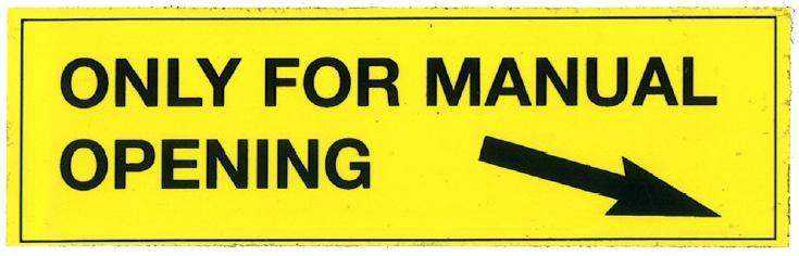
25 Manual Opening in Case of Emergency If elevator cannot be opened by compressed air, please follow these points: 1. Disconnect elevator air supply 2. For Latch opening use a steel bar (Pos.1). Be aware of the latch spring! WARNING: A steel bar could cause injuries due to the Latch spring force. Main Assembly 3. To open the elevator body remove the two screws (Pos.2) and the Cap (Pos.3). 4. Remove the Cotter pin (Pos.4) and unscrew the nut (Pos.5) until the elevator body is fully opened. 4 After maintenance or repair make sure that the nut (Pos.5) is returned to it`s originally position. Make sure all safety elements and warning signs are in place and undamaged. OPERATIONS Manual opening in Case of Emergency 25
.")


26 Manual Closing of the Elevator WARNING: Close B+V ACL / VES-ACL Elevators only with help of the B+V Trigger Closing Tool PN TCT (optional). Remove Trigger Closing Tool from Elevator after every time of use. Trigger Closing Tool OPERATIONS WARNING: Never use tools like hammers or bars to close ABVC-200 Sliptype Elevators. Use always the B+V Trigger Closing Tool to close the Elevators First example of wrong closing method Handling the Trigger Closing Tool Elevator is hanging free, just above drill floor Make sure the Trigger Locking Pin is removed Second example of wrong closing method 26


27 Depending to different Hammer sizes: Turn back Spindle to maximum opening measure of Trigger Closing Tool first. Put the Trigger Closing Tool on top of the Trigger System as shown below. Position of Locking Pin Turning the screw adjusts the Trigger Closing Tool, so there is no space in front to the hammer and no space to the rear of Trigger System. OPERATIONS Adjust to fit WARNING: It is dangerous around the Latch area: no personnel or objects allowed Release air pressure from the Elevator. Scetch of TCT 27


28 Hold down the Trigger Closing Tool with one hand Use the wrench with the other hand By turning the screw the Hammer of Trigger System is slowly drawn backwards. How to close the Elevator WARNING: While turning the screw double check that nobody is in front of the elevator! The elevator will close suddenly and quick after a few turns of the screw. There is an extreme danger of injuries. OPERATIONS Keep distance while working on the TCT Remove Trigger Closing Tool from Elevator after every time of use. Elevator in closed position 28


29 Trigger Closing Tool must be taken off the Elevator after every time of use. Example of Elevator without TCT OPERATIONS 29
30 OPERATIONS 30
31 MAINTENANCE & INSPECTION MAINTENANCE & INSPECTION 31

32 5. Maintenance and Inspection General If cracks, excessive wear etc. is recognised, contact Blohm + Voss Repair GmbH or an authorised service company. Weldings of the castings should be done only by Blohm + Voss Repair GmbH or an authorised service company in according to Blohm+Voss welding procedure. A regular preventative maintenance program should be established for all elevators. These written maintenance procedures should be given to the crew or maintenance personnel. WARNING: For Service and Maintenance disconnect the air supply. While working at the open elevator, the trigger has to be in the locked position. Daily Lubrication Lubricate Hinge Pins and Latch Pins (Grease Nipples). Lubricate Springs and Trigger System. Lubricate Emergency Opening and Actuator. Daily Inspection Inspect visually the Latch Opening Arrangements and Actuator with springs. MAINTENANCE & INSPECTION Grease points Grease point 1: Hinge Pin Grease point 2: Trigger Lever Grease point 3: Trigger Grease point 4: Latch Pin Grease point 5: Bearing Pin Grease point 6: Elevator Hinge Daily Test The Function of the Feedbacksignal has to be checked daily. If any damage or malfunction were found, take the elevator out of service for repair. Position of Locking Pin Locking of screws 6 All Screws are normally secured by a mechanical bolt lock or with a safety wire. All other screws are secured by metal adhesive (Locktite). Greasing Points 5 32

33 Grease Quality In order to achieve efficient greasing even at different environmental temperatures, we recommend the following grease types should be used (obtainable from Blohm + Voss Oil Tools): Low-Viscosity grease Type AVIATICON Grease XRF Alternatively; Use EP1 gear lubricating grease for greasing non-oil tight gear trains when temp. < 0 C/32 F. Use EP2 when temp. > 0 C/32 F. Recommended grease gun WARNING: Ensure to wear personal safety protection like gloves and safety glasses when handling hydraulic oil and/or grease. Oil and grease may be potentially harmfull for skin and eyes. MAINTENANCE & INSPECTION 33
34 Inspection categories acc. to API RP 8B MAINTENANCE & INSPECTION Category I This category involves observing the equipment during operation for indications of inadequate performance. When in use, equipment shall be visually inspected on a daily basis for cracks, loose fits or connections, elongation of part, and other signs of wear, corrosion or overloading. Any parts found to show cracks, excessive wear, etc., shall be removed from service for further examination. The equipment shall be visually inspected by a person knowledgeable in that equipment and its function. Category II This is Category I inspection plus further inspection for corrosion, deformation, loose or missing components, deterioration, proper lubrication, visible external cracks, and adjustment. Category II may involve some disassembly to access specific components and to identify wear that exceeds the allowable tolerances. Category III This is Category II inspection plus further inspection, which should include NDT of critical areas and may involve some disassembly to access specific components and to identify wear that exceeds the allowable tolerances. Prior to inspection, all foreign material such as dirt, paint, grease, oil, scale, etc. shall be removed from the concerned parts by a suitable method (e.g. paint-stripping, steam-cleaning, grit-blasting). Category IV This is Category III inspection plus further inspection for which the equipment is disassembled to the extent necessary to conduct NDT of all primary-load-carrying components. Equipment shall be: disassembled in a suitableequipped facility to the extent necessary to permit full inspection of all primary-loadcarrying components and other components that are critical to the equipment. inspected for excessive wear, cracks, flaws and deformation. Procedure: Corrections shall be made in accordance with the manufacturer s recommendations. Prior to inspection, all foreign material such as dirt, paint, grease, oil, scale, etc. shall be removed from the concerned parts by a suitable method (e.g. paintstripping, steam-cleaning, gritblasting) Frequency Periodic inspection The recommended schedule for inspection of all kind of Elevators: Ongoing I Daily: II 6 Monthly: III 1 Year: IV The recommended frequencies apply for equipment in use during the specified period. The inspection frequencies are only recommendations. The schedule of inspection heavily depends on the following factors: environment load cycles regulatory requirements operating time testing repairs re manufacture Non-periodic inspection A complete, on-job, shut-down inspection equivalent to the periodical Category III or Category IV should be made before (if anticipated) and after critical jobs (e.g., running heavy casing / drill strings, jarring, pulling on stuck pipes and/or operating at extreme low temperatures) <-20 C (<-4 F). Inspection A thorough inspection should be carried out periodically (every 3 months) or as special circumstances may require. Before starting an inspection disconnect any hydraulic/pneumatic system and remove all foreign materials (dirt, paint, grease Oil, scale, etc.) from surface by a suitable method. After a field inspection, it is advisable to record the extent of testing and testing results. Conduct the periodic or critical load inspection in the field by the crew with the supervisor. If cracks, excessive wear etc. is recognized, contact Blohm + Voss Oil Tools or an authorized service company. Inspection of Hydraulic/ Pneumatic System Check for leakage every day. Should internal or external leakage reach an unacceptable high level, contact Blohm + Voss Oil Tools or an authorized service company. 34
35 Critical Load Inspection Critical loads may occur. For example: impact loads such as jarring, pulling on stuck pipe, etc. If critical loads occurred unexpectedly, conduct the inspection immediately. Dismantling Inspection Generally, when the equipment returns to base, warehouse, etc. Carry out the Tool inspection, immediately. Furthermore, control it prior to its being sent on the next job. The Tool should be dismantled and inspected in a suitably equipped facility for excessive wear, cracks, flaws or deformations. Corrections should be made in accordance with recommendations which can be obtained from Blohm + Voss Oil Tools. Weldings at the castings should be done only by Blohm + Voss Oil Tools or an authorized service company in according to Blohm+Voss welding procedure. When need is shown in a field inspection, dismantle the Tool and arrange an inspection in a suitably equipped facility. Springs should be carefully visually inspected for excessive wear and obvious weakness. MAINTENANCE & INSPECTION 35
36 INSPECTION CHECK LISTS CHECK LIST FRONT PAGE TYPE OF EQUIPMENT SERIAL NUMBER PART NUMBER SUPERVISOR DATE OF INSPECTION INSPECTION CATEGORY PLACE OF INSPECTION MAINTENANCE & INSPECTION 36
37 Check Category I (Ongoing observation) Observe during operation for inadequate performance Check List Category II (Daily) CHECK FOR THE FOLLOWING GENERAL ISSUES (but not limited to): DESCRIPTION CHECKED SIGNATURE 1 Complete front page of check list for the records OK 2 Check for correct size of elevator or slip segments OK 3 Check correct function elevator latch indicator (open - red- or closed - green-) OK 4 Check function of feedback signal (elevator closed) OK 5 Check state of lubrication OK 6 Check functioning of elevator as a whole OK Remarks CHECK FOR LOOSE ITEMS, ESPECIALLY FOR (but not limited to): DESCRIPTION CHECKED SIGNATURE 1 Hinge pins, bolts and retainers OK 2 Fixation of slip segments OK 3 Screws, bolts, nuts, washers, retainers, springs and lock wire OK 4 Trigger hammer OK 5 Link blocks OK 6 Check completeness and condition of warning plates and labels OK Remarks CHECK FOR CRACKS, ELONGATION, DAMAGE AND CORROSION, ESPECIALLY FOR (but not limited to): DESCRIPTION CHECKED SIGNATURE 1 Elevator Body and Door OK 2 Hing pins, bolts, nuts OK 3 Slip segments OK 4 Latch and lug OK 5 Closing arrangement OK 6 Trigger arrangement OK Remarks MAINTENANCE & INSPECTION PNEUMATIC DESCRIPTION CHECKED SIGNATURE 1 Check for loose fittings, pipes, valves OK 2 Check for pneumatic leaks (hoses, valves and cylinders) OK 3 Check condition of pneumatic couplings and connection hoses OK Remarks SUPERVISOR DATE 37
38 Check List Category III (every 6 months) GENERAL DESCRIPTION CHECKED SIGNATURE 1 Carry out an Category II inspection OK 2 NDT (MPI) critical areas. Some disassembly may be needed to do so OK 3 Check parts for wear according to allowable tolerances. OK Remarks Check List Category IV (every year) GENERAL DESCRIPTION CHECKED SIGNATURE 1 Carry out an Category III inspection OK 2 NDT (MPI) critical areas and load bearing components. Strip elevator to do so OK 3 Change all pneumatic hoses and fittings OK 4 Check condition of pneumatic valves and replace if necessary OK Remarks MAINTENANCE & INSPECTION SUPERVISOR DATE 38
39 Wear data criteria Bore of Door and Body hinge pins Bore Body Hinge Pin Dimension new max: Dimension worn max: Bore Door Hinge Pin Dimension new max: Dimension worn max: mm mm mm mm Measuring of wear To measure link ears it is necessary to use calipers and a ruler. Significant wear is restricted to the top link ear, it is here that the measurement is taken. Hinge Pins, Latch Pins and socket holes are not normally measured for wear in the field. When it becomes apparent that the Hinge or Latch Pins have more tolerances, the elevator should be dismantled for general engineering check up. Remanufacturing Remanufacturing and repair of critical areas or load bearing parts must be done only by B+V or an B+V authorized service company. Also minor cracks or defects, which may be removed by grinding without reducing safety or operation of the elevator, must be done only by B+V or an B+V authorized service company. Following the repair, the parts should again be inspected by an appropriate method to insure that the defect has been completely removed. If the elevator is defective beyond repair, destroy it directly. If it should turn out necessary to secure the open elevator for repair work, inspection, etc., fix the trigger with the locking pin after opening of the elevator. MAINTENANCE & INSPECTION 39
40 Critical Areas Critical Areas are striped Critical area's are hatched Critical Areas Trouble shooting MAINTENANCE & INSPECTION Elevator does not open Check connection for damages Check pneumatic pressure and flow rate Check function and adjustment of control valve Check function of Valve (3) (see Pneumatic diagram) Elevator does not close complete Check Latch and Latch Lock Springs for damage Check pneumatic System for damages 40
41 SIZE COMPONENTS SIZE COMPONENTS 41

42 6. Pipe sizes, Slip Segments and Trigger Hammers Pipe dimension Trigger Hammers Slip Segments 2 3 / / / / / / / / / / on request / 4 on request / 8 on request Note: ( - ) Trigger Hammers without Partnumbers will be manufactured on special request. Slips SiIZE COMPONENTS Slips and Hammers 42
43 DRAWINGS & SPARE PARTS 43 DRAWINGS & SPARE PARTS
44 Y Center Latch Elevator Parts list PN: Y Pos. Qty Part. No. Description Y Elevator Assembly BVC Latch Opening Unit Elevator Actuation Arrangement Trigger Assembly Welding Attachement Actuator Casing Welding Attachments Spring Lach Lock Assembly Hook for ABVC Safety Wire Hose Assembly Hose Assembly Stop and Go Valve DRAWINGS & SPARE PARTS 44
45 Y BVC-200 modified for ABVC Parts list PN: Y BVC Pos. Qty Part no. Description Elevator Frame Elevator Frame Latch Latch Lock Assembly Latch Lock Pin Latch Spring for ABVC Latch Lock Spring Rivet Pin Door Lug Pin Latch Pin Securing Ring Link Block Hinge Pin Assembly Clevis Pin with Head Safety Spring Screw Castle Nut Cotter Pin Slip Bolt Slip Spring Screw Latch Pin Assembly Serrated Lock Washer DRAWINGS & SPARE PARTS 45
46 Parts list PN: Hinge Pin Assembly Pos. Qty Part. No. Description Hinge Pin Securing Plate for Hinge Pin Safety Sheet Screw Grease Nipple Parts list PN: Latch Pin Assembly Pos. Qty Part. No. Description Latch Pin Securing Plate for Hinge Pin Safety Sheet Screw Grease Nipple DRAWINGS & SPARE PARTS 46
47 Latch opening unit PN: DRAWINGS & SPARE PARTS
48 Parts list PN: Latch Opening Unit DRAWINGS & SPARE PARTS Pos. Qty Part. No. Description Clevis Pin with Head Washer Cotter Pin Casing Latch opening system Screw Permaglide Bush Lock Nut Screw Nut Clevis Pin with Head Grease Nipple Spring Washer Cotter Pin Lever Bolt Bolt Latch Pin Securing Ring Pin Yoke Spiral Split Pin Latch Cylinder Screw Screw Double Socket Socket L-Adapter Straight Connection Seal Rings Equal Tee Pneumatic Hose Assembly, L=290mm Pneumatic Hose Assembly, L=360mm /2-Way-Valve Screw Washer Absorber II Adapter Rope Clamp I Cylinder Head Screw Rope Angle position indicator switch Screw Washer Screw 48
49 Parts list PN: Latch Opening Unit Pos. Qty Part. No. Description Nut Cover Assembly, middle Cover Plate Cover, left Cover, left behind Screw Spring Pneumatic Set III Reducing Nipple Quick Relief Valve Straight Bulkhead Coupling Pneumatic Hose Assembly 590 mm Pneumatic Hose Assembly 410 mm Standpipe Reducer Washer DRAWINGS & SPARE PARTS 49
50 PN Cover Assembly, Middle Parts list PN: Cover Assembly, Middle Pos. Qty Part. No. Description Cover, middle Indicator Disk Lever Holder for Indicator Disk Washer Cotter Pin Screw Washer Cotter Pin Tension Spring Tension Spring Screw Rope DRAWINGS & SPARE PARTS 50
51 Pneumatic Set WITH FEEDBACKSIGNAL PN: Pneumatic Set III R A P Latch Opening Arrangement Elevator Actuating Arrangement DRAWINGS & SPARE PARTS 51
52 Parts list PN: Pneumatic Set III Pos. Qty Part no. Description Elevator Cylinder Reducing Fitting Swivel Connection Adapter Distribubtion Block Plug Double Socket Socket Swivelling Screw Fitting Latch Cylinder Reducing Nipple Absorber II Quick-Relief-Valve /2-Way-Valve Equal Tee Straight Bulkhead Coupling L-Adapter Straight Connection Cover-Piece Straight-Socket EO-Pipe Clutch Hose Coupling Straight-Socket Seal Rings Pneumatic Hose 400mm Pneumatic Hose 250mm Pneumatic Hose 450mm Pneumatic Hose 5000 mm Pneumatic Hose 150mm Pneumatic Hose 900mm Standpipe Reducer Stop and Gio Valve Assembly DRAWINGS & SPARE PARTS 52
53 Elevator Actuation Arrangement PN: For ABVC-200 DRAWINGS & SPARE PARTS
54 Parts list PN: Elevator Actuation Arrangement DRAWINGS & SPARE PARTS Pos. Qty Part. No. Description Actuator Casing Actuator 3, 4 n/a Connection bar 6 na Spring support Spring support II Rod Bolt Actuating Pin I 12 na Castle nut Pressure Spring Pressure Spring Double Plate Hexagon nut Cylinder Head Screw Cylinder Head Screw Cylinder Head Screw 21, 22, 23 na Cotter pin Cover Cap Washer Cylinder head scew Connection bar Bolt Elevator cylinder Pneumatic cap Hexagon head screw Lock washer Swivel connection EO-pipe band Hose clip Air hose II Pipe socket Distribution block Straight socket EO-pipe Cover Piece Clutch hose coupling Reducing Fitting Double socket Socket Cylinder head scew Screw Cotter pin 54
55 Trigger Assembly PN: Parts list PN: Pos. Quantity Part no. Description Trigger Unit Hammer Mounting Grame DRAWINGS & SPARE PARTS 55
56 Trigger Unit ABVC 150/200 : PN DRAWINGS & SPARE PARTS 56
57 Parts list PN: Pos. Quantity Part no. Description Trigger Casing Slide Lever left Lever right Spindle Screw Taper Pin Spring Bolt Assembly for Hammer Bolt Bolt Castle Nut Cotter Pin Spring Type Straight Pin Latch Pin Securing Ring Retaining Ring Washer Grease Nipple Thread Pin Grease Fitting Safety Pin Sliding Bushing DRAWINGS & SPARE PARTS 57
58 Trigger Closing Tool PN: TCT Parts list PN: TCT Pos. Quantity Part no. Description Body Center Support Hexagon head screw Washer Cotter Pin Hexagonal Nut Threaded Pin PN Steel bar for Latch opening DRAWINGS & SPARE PARTS 58
59 Welding attachment actuator casing 2 1 Parts list PN: Pos. Qty Part. No. Description Upper Bushing Lower Bushing DRAWINGS & SPARE PARTS 59
60 Welding attachments to elevator Parts list PN: Pos. Qty Part. No. Description Upper flange Lower flange Link block right Link block left Upper eye plate door Upper eye plate body Lower eye plate door Lower eye plate body Knaggen DRAWINGS & SPARE PARTS 60
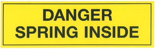
61 Spare Parts for one year operation Parts list PN: Y-RSP Pos. Quantity Part no. Description Hose Assembly Warning sign Spring Warning sign Blohm+Voss Warning sign Automatic Warning sign Hands Warning sign Grease Daily Hook for ABVC Safety Wire Hose Assembly Stop and Go Valve Parts list PN: Y-RSP Pos. Qty Part no. Description Latch Lock Latch Lock Pin Latch Spring Latch Lock Spring Latch Pin Securing Ring Securing Plate for Hinge Pin Safety Sheet Screw Grease Nipple Clevis Pin with Head Safety Spring Srew Castle Nut Cotter Pin Slip Bolt Slip Spring Screw Securing Plate for Hinge Pin Safety Sheet Screw Grease Nipple serrated Lock Washer DRAWINGS & SPARE PARTS 61
62 Parts list PN: RSP Pos. Quantity Part no. Description /2-Way-Valve Quick Relif Valve As an alternative to the single spare parts the hole Latch opening unit ( PN ) can be ordered completely. Parts list PN: RSP Pos. Quantity Part no. Description Cover, middle Tension Spring Tension Spring Rope As an alternative to the single spare parts the hole Latch opening unit ( PN ) can be ordered completely. Parts list PN: RSP Pos. Quantity Part no. Description Cap Cylinder Head Screw Pneumatic Cap Hexagon Head Screw Lock Washer Double Socket Socket Cylinder Head Screw Attention: Inside the Elevator Actuation Unit is assembled with heavy springs under high pressure! There is an extreme danger of injuries while disassembling, ifdisassembling is not done correctly. Therefore disassembling and repair is strictly permitted only for Blohm + Voss and their authorizied Service Facilities. Parts list PN: RSP Pos. Quantity Part no. Description Hammer for 2.3/8-2.7/ Hammer for 4.1/2-5.1/ Hammer for 5.5/8-7.5/8 DRAWINGS & SPARE PARTS 62
63 Parts list PN: RSP Pos. Quantity Part no. Description Lever left Lever right Screw Taper Pin Bolt Assembly for Hammer Bolt Bolt Latch Pin Securing Ring Retaining Ring Washer Grease Nipple Thread Pin Sliding Bushing Grease Fitting DRAWINGS & SPARE PARTS 63
Blohm+Voss Pipe Handling Equipment Special Link Connector Technical Documentation Original instructions
 Blohm+Voss Pipe Handling Equipment Special Link Connector Technical Documentation Original instructions Manual PN 554106-D Rev. 002, May 2012 Blohm + Voss Oil Tools 1 GENERAL INFORMATION Warnings and Note
TECHNICAL DOCUMENTATION
 Read before first use! VES-CL-1000 Elevator Hydraulically Operated Part No. 611000-Y-H Blohm + Voss Oil Tools Hermann-Blohm-Straße 2 20457 Hamburg Germany Telephone ++49 (0)40/3119-1826/1162 Fax ++49 (0)40/3119-8194
Blohm + Voss Pipe Handling Equipment VES-CL Center Latch Elevator, Manual Operated c/w Bushing Technical Documentation Original Instructions
 Blohm + Voss Pipe Handling Equipment VES-CL 150-1000 Center Latch Elevator, Manual Operated c/w Bushing Technical Documentation Original Instructions Manual PN 611000-Y-D Rev 003 February 2012 Blohm +
Blohm+Voss Pipe Handling Equipment Safety Clamps Type C and T Technical Documentation Original Instructions
 Blohm+Voss Pipe Handling Equipment Safety Clamps Type C and T Technical Documentation Original Instructions Manual PN 88003-D Rev. 010, August 2013 Blohm + Voss is a trademark of Blohm + Voss Shipyards
Blohm + Voss Pipe Handling Equipment SDS Side Door Elevators 65, 100, 150, 250, 350 & 500 tons Technical Documentation Original Instructions
 Blohm + Voss Pipe Handling Equipment SDS Side Door Elevators 65, 100, 150, 250, 350 & 500 tons Technical Documentation Original Instructions Manual PN 641020-Y-BC-D Rev 013, Mai 2013 Blohm + Voss Oil Tools
Blohm+Voss Pipe Handling Equipment FPS 500-AIR Flush Power Slip Technical Documentation Original Instructions
 Blohm+Voss Pipe Handling Equipment FPS 500-AIR Flush Power Slip Technical Documentation Original Instructions Manual 754000-AIR-D Rev 000, October 2012 Blohm + Voss Oiltools 1 GENERAL INFORMATION Warnings
Blohm + Voss Oil Tools
 Blohm + Voss Pipe Handling Equipment Rotary Hand Slips: RSM / RSX / LRS Drill Collar Slips: DCS / DCM / DCL Casing Slips: CSL / CSC Technical Documentation Original Instructions Manual PN 83500-D Rev 008,
Blohm + Voss Pipe Handling Equipment BVE / BVS 750 Frame 1 air operated 4.1/2 14 Technical Documentation Original Instructions
 Blohm + Voss Pipe Handling Equipment BVE / BVS 750 Frame 1 air operated 4.1/2 14 Technical Documentation Original Instructions Manual PN 710000-Y-A-D Rev 004, February 2012 Blohm + Voss Oil Tools 1 GENERAL
Blohm+Voss BVE/S-750 Elevator/Spider 4 ½ 14 Pipe Range Diameter
 Read before first use! Blohm+Voss BVE/S-750 Elevator/Spider 4 ½ 14 Pipe Range Diameter Part No. 710000-Y-H hydraulic version Blohm + Voss Oil Tools Hermann-Blohm-Straße 2 20457 Hamburg Germany Telephone
Blohm+Voss. BVE / BVS /8 7.5/8 250 metric tons
 Blohm+Voss BVE / BVS 250 2.3/8 7.5/8 250 metric tons Part-No. 725000 READ THESE INSTRUCTIONS BEFORE USE! Blohm+Voss Oil Tools Hermann-Blohm-Straße 2 20457 Hamburg Germany Telephone ++49 (0)40/3119-1826/1162
Blohm + Voss Oil Tools
 Blohm+Voss Pipe Handling Equipment Hydraulic Operated Elevator/Spider BVE / BVS 500 PN 752000-Y-H-VC 4.1/2-14 Technical Documentation Original Instructions Manual PN 752000-Y-H-VC-D Rev 001, February 2012
Blohm + Voss Oil Tools
 Blohm+Voss Pipe Handling Equipment VES-HCL 350 Elevator Hydraulically Operated Part no. 63000-Y-H-F (with closing signal) Technical Documentation Original Instructions Manual PN 63000-Y-H-F-D Rev 005 valid
Blohm + Voss B+V hinged Adapter
 Blohm + Voss B+V hinged Adapter 49 /2 to 37 /2 for RT National Inspection and maintenance procedure Part No. 55320 Blohm+Voss Oil Tools Hermann-Blohm-Straße 2 20457 Hamburg Germany Telephone ++49 (0)40/39-826/62
CONTROL UNIT FOR POWER SLIPS PN:
 CONTROL UNIT FOR POWER SLIPS PN: 757105 Blohm + Voss Oiltools Herrmann-Blohm-Strasse 2 20457 Hamburg Germany Telephone ++49 (0)40/3119-1826/1162 Fax ++49 (0)40/3119-3305 Revision 001, February 2012 All
BVM Corporation TYPE MS TONG 6,500 FT/LBS. TORQUE
 Page 1 BVM Corporation TYPE MS TONG 6,500 FT/LBS. TORQUE Part number: Serial Number: BVM CORPORTION TYPE MS TONG 6,500 FT/LBS. TORQUE WRNING: Manual tongs which have experienced excessive wear or are found
Pipe Handling Equipment
 Pipe Handling Equipment Blohm+Voss Repair GmbH Oil Tool Division Hermann-Blohm-Straße 2 20457 Hamburg, Germany Phone: +49-40-31 19-81 42 Fax: +49-40-31 19-34 00 E-mail: info@blohmvoss-oiltools.com www.blohmvoss-oiltools.com
Before equipment use, please read this operation manual carefully. Serial Number: Date Purchased:
 Pushed & Geared Trolleys OPERATION MANUAL This operation manual is intended as an instruction manual for trained personnel who are in charge of installation, maintenance, repair etc. Before equipment use,
Blohm + Voss Oil Tools, LLC GraySpin Mark 40 Hydraulic Drill Pipe Spinner With and without Hydraulic Lift Technical Documentation
 Blohm + Voss Oil Tools, LLC GraySpin Mark 40 Hydraulic Drill Pipe Spinner With and without Hydraulic Lift Technical Documentation 1 GENERAL INFORMATION Warnings and Notes WARNING: A WARNING INDICATES A
Translation of the Original operating instructions Lifting device Z 70 /...
 Translation of the Original operating instructions Lifting device Z 70 /... Content 1. Lifting device / Correct use according to regulations 2. Basic principles 3. General information 4. Special remarks
Safety Clamp Operation Manual
 TECHNICAL MANUAL Safety Clamp Operation Manual 2005-2016 Texas International Oilfield Tools, LTD. Published by Texas International Oilfield Tools, LTD, Engineering 14620 Henry Road. Houston, TX 77060 www.texasinternational.com
Installation Operation Maintenance. LSSN Butterfly Valve AGA Approved 50MM - 150MM. QAD#IM6055.REVA
 LSSN Butterfly Valve Installation Operation Maintenance Licence Number: 5326 www.challengervalves.com.au 1 Index 1. INTRODUCTION 1.1 Design Features 3 1.2 Flange and Pipe Compatibility 4 1.3 Operating
HST -LS Interlocking device (Translation of Original Manual)
") Installation and Operating Manual for Components HST -LS Interlocking device (Translation of Original Manual) HST-LS Ident.-No.: 10268 HST-LS Ident.-No.: 10269 HST-LS, pictured Ident-Nr. 10269 The image
Installation and Operating Manual for Components HST -LS Interlocking device (Translation of Original Manual) HST-LS Ident.-No.: 10268 HST-LS Ident.-No.: 10269 HST-LS, pictured Ident-Nr. 10269 The image
Lineman s Hoist. Operating, Maintenance & Parts Manual. Follow all instructions and warnings for LMST680-2
 Lineman s Hoist LMST0- Operating, Maintenance & Parts Manual Lineman s Hoist Follow all instructions and warnings for inspecting, maintaining and operating this hoist. The use of any hoist presents some
Operating & Maintenance Manual For Steam Conditioning Valve
 For Steam Conditioning Valve 1 Table of Contents 1.0 Introduction 3 2.0 Product description 3 3.0 Safety Instruction 4 4.0 Installation and Commissioning 5 5.0 Valve Disassembly 6 6.0 Maintenance 6 7.0
Instruction Manual. Unique 7000 Series Aseptic - Manually Operated ESE02421-ENUS Original manual
 Instruction Manual Unique 7000 Series Aseptic - Manually Operated 2210-0042 ESE02421-ENUS1 2013-03 Original manual Table of contents The information herein is correct at the time of issue but may be subject
Mounting and Operating Instructions EB 8039 EN. Type 3351 Pneumatic On/off Valve. Type 3351 Pneumatic On/off Valve. Type 3351 Pneumatic On/off Valve
 Type 3351 Pneumatic On/off Valve Type 3351 Pneumatic On/off Valve Type 3351 Pneumatic On/off Valve Version with handwheel Mounting and Operating Instructions EB 8039 EN Edition May 2016 Definition of signal
HYDRAULIC PALLET TRUCK. MODEL No: PTE550 PART Nos OPERATION & MAINTENANCE INSTRUCTIONS
 HYDRAULIC PALLET TRUCK MODEL No: PTE550 PART Nos 7630171 OPERATION & MAINTENANCE INSTRUCTIONS 0604 Please read these instructions carefully before operating the truck Thank you for purchasing this CLARKE
Technical Description Edition 2007 Mounting, maintenance and repair of propshafts with flanged universal joints
 Technical Description Edition 2007 Mounting, maintenance and repair of propshafts with flanged universal joints 1. Recommendations Assembly, disassembly, maintenance and repair of propshafts should be
INSTRUCTION MANUAL. Pacific Self-locking Beam Trolleys Pacific Adjustable Angle Clamps Pacific Top Girder Clamps
 INSTRUCTION MANUAL Pacific Self-locking Beam Trolleys Pacific Adjustable Angle Clamps Pacific Top Girder Clamps IMPORTANT Please read this instruction manual before using these products. This manual contains
OPERATIONS MANUAL LEVER CHAIN HOIST
 OPERATIONS MANUAL LEVER CHAIN HOIST IMPORTANT SAFETY INFORMATION Please read, understand and follow all safety information contained in these instructions prior to the use of this hoist. Retain these instructions
Premium Supply. Direct Push. Models PCK-3530-DP PCK DP PCK-530-DP. Operator s Manual and Installation Instructions
 Direct Push Models PCK-3530-DP PCK-3530-2DP PCK-530-DP Operator s Manual and Installation Instructions Premium Supply 2038 West Interstate 30 866-934-0777 Proud members of: and June 20, 2018 Table of Contents
Mounting and Operating Instructions EB 8111/8112 EN. Valve Series V2001 Globe Valve Type 3321
 Valve Series V2001 Globe Valve Type 3321 Fig. 1 Type 3321 Valve with mounted rod-type yoke for pneumatic or electric actuators (partial view) Mounting and Operating Instructions EB 8111/8112 EN Edition
Instruction Manual For Auto Shift Hydraulic Lift Table
 Instruction Manual For Auto Shift Hydraulic Lift Table Model Number: CART-550-AS Note: Owner/Operator must read and understand this Instruction Manual before operating the lift & tilt table. Contents 1
Blohm + Voss Oil Tools Circular Buttons, Inserts and Dies Catalog
 Blohm + Voss Oil Tools Circular Buttons, Inserts and Dies Catalog A company of ThyssenKrupp Marine Systems Blohm + Voss Repair Blohm + Voss Oil Tools General Information Brochure Contents INSERTS: DIMENSIONS...
MEYER-Rotating Fork Positioners are attachments used to transport loads and replace
 This MEYER-Attachment complies in every aspect to the EC-Safety Guidelines. The Certificate of Conformation / Declaration by the Manufacturer has been delivered with the attachment. The CE-Symbol can be
Operating Instructions For Your LUG-ALL Cable Winch-Hoist
 LAC-0108 Rev. 5/08 Operating Instructions For Your LUG-ALL Cable Winch-Hoist 604 Hemlock Road, Morgantown, PA 19543 Phone: (877) 658-4255 / Fax: (610) 286-9661 / Web: www.lug-all.com Copyright 2008 LUG-ALL
Mounting and Operating Instructions EB 8135/8136 EN. Series V2001 Valves Type 3535 Three-way Valve for Heat Transfer Oil
 Series V2001 Valves Type 3535 Three-way Valve for Heat Transfer Oil Type 3535 Three-way Valve with bellows seal and rod-type yoke (partial view) Mounting and Operating Instructions EB 8135/8136 EN Edition
Distributed by Tri-State Equipment Company Inc. Web: PH: FAX:
 Lineman s Hoist Distributed by Tri-State Equipment Company Inc. Email: sales@tsoverheadcrane.com Web: www.tsoverheadcrane.com PH: -869-00 FAX: -869-6 LMST680 Operating, Maintenance & Parts Manual Lineman
Top Drive System Installation and Commissioning Manual
 TDS-1000A Top Drive System Installation and Commissioning Manual SM01040 General Information Conventions.............................. 1-3 Notes, Cautions, and Warnings......................... 1-3 Illustrations.........................................
Provided by: Operating, Maintenance & Parts Manual
 Provided by: www.hoistsdirect.com TB681.qxd 11/29/2004 3:04 PM Page 1 Operating, Maintenance & Parts Manual TB603 Manually Lever Operated Chain Hoist 1100 POUNDS MAXIMUM CAPACITY (500 kg) Follow all instructions
Fisher 3024C Diaphragm Actuator
 Instruction Manual 3024C Actuator Fisher 3024C Diaphragm Actuator Contents Introduction... 1 Scope of Manual... 1 Description... 2 Specifications... 3 Installation... 5 Mounting the Actuator on the Valve...
Safelift Overhead Runway Beams & Rolling Beam Cranes
 Operation & Maintenance Instructions Instructions for Safe Use Safelift Overhead Runway Beams & Rolling Beam Cranes Certification Safelift overhead runway beams and rolling beam cranes are lifting appliances
Serial N... MX1 Chain Driven Pipe Cutting and Bevelling Machine Parts and Operating Manual
 Serial N... MX1 Chain Driven Pipe Cutting and Bevelling Machine Parts and Operating Manual Table of contents Section Description Page 1.0 General Information 2 2.0 Specification 2 2.1 General Specification
HYDRAULIC PALLET TRUCKS
 HYDRAULIC PALLET TRUCKS HYDRAULIC PALLET TRUCKS MODEL Nos: PT550 GAL & PT685 GAL PART Nos: 7630234 & 7630236 OPERATION & MAINTENANCE INSTRUCTIONS 0204 Please read these instructions carefully before operating
STRUT SPRING COMPRESSOR
 OWNER S MANUAL PRODUCT CODE: 1221T STRUT SPRING COMPRESSOR Capacity Stroke Spring Coil Spring Spring Coil Net Weight (Maximum) Thickness Length Diameter 1,000kg 330mm 10-18mm 210-570mm 100-158mm 36kg Made
HYDRAULIC SPREADER. Max. Pressure: 10,000 PSI (700 BAR) Unit Weight: HS2000 = 4.8 LBS. (2.17 Kg) HS3000 = 22 LBS. (9.98 Kg)
 Unit Weight: HS2000 = 4.8 LBS. (2.17 Kg) HS3000 = 22 LBS. (9.98 Kg)") Form No. 103525 Operating Instructions for: HS2000 HS3000 HYDRAULIC SPREADER Max. Pressure: 10,000 PSI (700 BAR) Unit Weight: HS2000 = 4.8 LBS. (2.17 Kg) HS3000 = 22 LBS. (9.98 Kg) Definition: Hydraulic
Form No. 103525 Operating Instructions for: HS2000 HS3000 HYDRAULIC SPREADER Max. Pressure: 10,000 PSI (700 BAR) Unit Weight: HS2000 = 4.8 LBS. (2.17 Kg) HS3000 = 22 LBS. (9.98 Kg) Definition: Hydraulic
Mounting and Operating Instructions EB 8111/8112 EN. Series V2001 Valves Type 3321 Globe Valve
 Series V2001 Valves Type 3321 Globe Valve Type 3321 Globe Valve with rod-type yoke and Type 3372 Electropneumatic Actuator (350 cm²) Mounting and Operating Instructions EB 8111/8112 EN Edition June 2013
Operating Manual TWN 0121/1. Lifting point, screw-type TWN 0122 TWN 0123 TWN 0127 TWN 1120 TWN 1830 TWN 1890
 TWN 0121/1 Operating Manual Lifting point, screw-type TWN 0122 TWN 0123 TWN 0127 TWN 1120 TWN 1830 TWN 1890 THIELE GmbH & Co. KG Werkstraße 3 Tel: +49 (0)2371 / 947-0 58640 Iserlohn www.thiele.de B07905-D
PAGE 1 OF 5 HEALTH, SAFETY & ENVIRONMENTAL MANUAL PROCEDURE: S360 Overhead Cranes & Lifts Procedure REV 4.0 8/14/2012
 PAGE 1 OF 5 PURPOSE: OVERHEAD CRANES AND LIFTS PROCEDURE The purpose of this procedure is to define the safety and training requirements for use of overhead cranes and lifts. Procedure: Definitions Designated
Star Swivel-Arm Hoist Installation and Operating Instructions
 Star Swivel-Arm Hoist Installation and Operating Instructions Conveying & Hoisting Solutions P/L ABN 78 6 7. Purpose of Equipment Star Swivel-Arm Hoists are intended for the transport of materials. Star
Mounting and Operating Instructions EB 8097 EN. Type and Type Pneumatic Control Valves
 Type 3347-1 and Type 3347-7 Pneumatic Control Valves Type 3347-7, cast body with welding ends Type 3347-7, bar stock body with threaded connections Mounting and Operating Instructions EB 8097 EN Edition
AC 100. Operating instructions Pneumatic Crimper AC 100. Date of issue: 05/2010. Keep for future use!
 Operating instructions Pneumatic Crimper AC 100 Date of issue: 05/2010 Keep for future use! SAFETY SAFETY Basic information The basic prerequisite for ensuring safe use and continuous operation of the
20 TONNE HYDRAULIC PRESS MODEL NO: CSA20FBT
 20 TONNE HYDRAULIC PRESS MODEL NO: CSA20FBT PART NO: 7614058 OPERATION & MAINTENANCE INSTRUCTIONS WARNING: Read these instructions before using the press GC0516 INTRODUCTION Thank you for purchasing this
INSTALLATION, OPERATION AND MAINTENANCE INSTRUCTIONS
 INSTALLATION, OPERATION AND MAINTENANCE INSTRUCTIONS Contents Section 1. General Observations... 2 2. Operation... 4 3. Control During Operation... 5 4. Trouble Shooting... 6 5. Maintenance... 7 Please
Declaration of Conformity as per Directive 97/23/EC
 Declaration of Conformity as per Directive 97/23/EC The manufacturer declares that:, 47906 Kempen, Germany PTFE-lined Rotary plug valves Series 23e, with packing with lever for 90 operation with worm gear
1/4 Die Grinder. Please read and fully understand the instructions in this manual before operation. Keep this manual safe for future reference
 Please dispose of packaging for the product in a responsible manner. It is suitable for recycling. Help to protect the environment, take the packaging to the local amenity tip and place into the appropriate
Maintenance Manual. 3-Inch Internal Valve. F660 Series
 3-Inch Internal Valve F660 Series LIST OF EFFECTIVE PAGES On a revised page, the portion of text or illustrations affected by the change is indicated by a vertical line in the outer margin of the page.
Maintenance Manual 3-INCH INTERNAL VALVE F660 SERIES
 Maintenance Manual 3-INCH INTERNAL VALVE F660 SERIES REVISION 1.1 03/15/2002 LIST OF EFFECTIVE PAGES On a revised page, the portion of text or illustrations affected by the change is indicated by a vertical
Type Operating Instructions. Bedienungsanleitung Manuel d utilisation
 Globe control valve, pneumatically operated Actuator sizes 40 mm - 125 mm, Nominal diameter DN10-65 Kolbengesteuertes Geradsitzventil Antriebsgrößen 40 mm - 125 mm, Nennweiten DN10-65 Vanne à siège droit
Mounting and Operating Instructions EB 8048 EN. Type and Type Pneumatic Control Valves Type 3249 Aseptic Angle Valve
 Type 3249-1 and Type 3249-7 Pneumatic Control Valves Type 3249 Aseptic Angle Valve Ball body version Special version with packing Type 3249-7 Control Valve with Type 3277 Actuator and integrated positioner
Rectangular Door L-VAT with pneumatic actuator double acting
 Rectangular Door L-VAT with pneumatic actuator double acting This manual is valid for the products: 0 7 5 1 0 U A 2 4 0 0 0 1 4 character option code Size 10... 46 x 236 12... 50 x 336 Actuator 24... without
Hydraulic Breakers HH35. Prior to Operation. From Serial No Revised We thank you for choosing a HYCON breaker.
 Hydraulic Breakers HH35 From Serial No. 12263 Revised 01.02.2015 Prior to Operation We thank you for choosing a HYCON breaker. To ensure smooth operation and long-lasting performance of your new breaker,
Side Door Elevator SDS
 Pipe-Handling-Equipment Hoisting Equipment Side Door Elevator SDS SDS / VES SDS / SDS-H Type Series Manual and hydraulic operated elevators SDS Type Series Side Door Collar Type Elevator VES SDS Type Series
500kg HYDRAULIC TABLE LIFT
 Product Code: 6007T OWNER S MANUAL PRODUCT CODE: 6007T 500kg HYDRAULIC TABLE LIFT Working Load Limit 500kg Maximum Height 1575mm Minimum Height 440mm Table Dimensions 1010x520mm Wheel Diameter 150mm Made
Instruction Manual. SMP-BCA Aseptic Mixproof Valve with PTFE Diaphragm IM70811-EN
 Instruction Manual SMP-BCA Aseptic Mixproof Valve with PTFE Diaphragm IM70811-EN3 2010-04 Declaration of Conformity The designating company Alfa Laval Company Name Albuen 31, DK-6000 Kolding, Denmark
GT-200 GATE VALVES PN16, Screwed end
 Document No. : MD-QO-04-281 Date : 2009/07 /17 Version : 1.0 GT-200 GATE VALVES PN16, Screwed end USER MANUAL Modentic Industrial Corporation 14F-1,No.57Taya Rd.,Taichung,Taiwan,R.O.C. Email:modentic@ms9.hinet.net
Lincoln Hoist. Web Hoist Operating Manual. Lincoln Hoist
 Lincoln Hoist Web Hoist Operating Manual Lincoln Hoist Mfg. by Lincoln Precision Machining Company 121 Creeper Hill Road, P.O. Box 458, North Grafton, MA 01536 USA Toll Free (888) 306-7222 Phone (774)
SERVICE GUIDE For WARN PULLZALL 24Vdc P/N &
 SERVICE GUIDE For WARN PULLZALL 24Vdc P/N 885005 & 885006 REPAIR / REPLACEMENT INSTRUCTIONS TROUBLE SHOOTING GUIDE 987606A1.doc Page 1 of 46 WARNING This guide identifies potential hazards and has important
Baumann Mikroseal Control Valve
 Instruction Manual 81000 Valve Baumann 81000 Mikroseal Control Valve Contents Introduction... 1 Scope of Manual... 1 Safety Precautions... 2 Maintenance... 3 Installation... 3 Air Piping... 4 Flow Direction...
Miller Compact Manual Quick Couplers
 Miller: Issue 2 Miller Compact Manual Quick Couplers For Mini Excavators (1 to 10 tonne) and Backhoe Loaders Installation Guide and Operator s Instructions IMPORTANT Keep this manual with the machine at
Operating and installation instructions
 DP30 DP32 DP33 DP34 Contents 1.0 General information on operating instructions... 2-2 2.0 Notes on possible dangers... 2-2 2.1 Significance of symbols... 2-2 2.2 Explanatory notes on safety information...
JARVIS. BRE -1 and BRE -2 BUNG RING EXPANDER EQUIPMENT... TABLE OF
 BRE -1 and BRE -2 BUNG RING EXPANDER EQUIPMENT SELECTION... Ordering No. TABLE OF CONTENTS... Page BRE--1... 4021002 BRE--2... 4021008 Air Hose, 16 feet long... 1059002 Balancer... 4042043 Notice to Employer
OPERATION SERVICE PARTS TUGIT2. Manually Operated Short Handle Lever Hoist A3140-XXX
 OPERATION SERVICE PARTS TUGIT2 Manually Operated Short Handle Lever Hoist A3140-XXX Sold & Serviced by Morgan Aero 1450 80 th Street SW Everett WA U.S.A. 425/438.9600 SAFETY PRECAUTIONS WARNING! Improper
Baumann Way Control Valve
 Instruction Manual 24003 Valve Baumann 24003 3-Way Control Valve Contents Introduction... 1 Scope of Manual... 1 Safety Precautions... 2 Educational Services... 3 Maintenance... 3 Installation... 3 Air
ov-lifting_bolts_divider - Updated Lifting Bolts
 ov-lifting_bolts_divider - Updated - 09-01-2017 Lifting Bolts Technical Information roduct information Lifting Bolts roduct marking Compliant with 2006/42/EC, and with individual date of manufacture and
Instruction Manual. Single Acting Hydraulic Aluminium Pull Cylinders RAP Series. Maximum Operating Pressure 700 bar
 Single Acting Hydraulic Aluminium Pull Cylinders RAP Series Maximum Operating Pressure 700 bar ABSOLUTE EQUIPMENT PTY LTD 2/186 Granite Street, GEEBUNG QLD 4034 Australia sales@absoluteequipment.com.au
Storage, operating and maintenance instructions for AZ plug valves and Standard valves
 ARMATUREN Plug - Valves metallic with PTFE Sleeve 2-7 way Storage, operating and maintenance instructions for AZ plug valves and Standard valves Plug - Valves FEP/PFA - lined, 2-3 way Butterfly - Valves
50 TONNE HYDRAULIC PRESS MODEL NO: CSA50FP
 50 TONNE HYDRAULIC PRESS MODEL NO: CSA50FP PART NO: 7615202 OPERATION & MAINTENANCE INSTRUCTIONS WARNING: Read these instructions before using the press GC0516 INTRODUCTION Thank you for purchasing this
Single Post Caliper Brake VC500
 Single Post Caliper Brake VC500 1 In accordance with Nexen s established policy of constant product improvement, the specifications contained in this manual are subject to change without notice. Technical
Safe Operating Practices & Maintenance Manual
 tcamerican.com sales@tcamerican.com 763-479-7000 11110 Industrial Circle NW, Suite A, Elk River, MN 55330 Safe Operating Practices & Maintenance Manual Section Subject Page A. General 2 B. Operator Qualifications
MEX (55) QRO (442) Web Controls
 QRO (442) Web Controls") Web Controls SINGLE AND DUAL ROTOR TENSION CONTROL BRAKES MODELS:,,,, AND INSTALLATION, OPERATION, AND MAINTENANCE INSTRUCTIONS Read this manual carefully, making full use of its explanations and instructions.
Web Controls SINGLE AND DUAL ROTOR TENSION CONTROL BRAKES MODELS:,,,, AND INSTALLATION, OPERATION, AND MAINTENANCE INSTRUCTIONS Read this manual carefully, making full use of its explanations and instructions.
Standard Valves Series Globe Valves Series Angle Valves Series Way-Valves
 Installation, Operation, Maintenance Instructions Standard Valves Series 035 000 Globe Valves Series 031 000 Angle Valves Series 033 000 3-Way-Valves 1 GENERAL INFORMATION These instructions are designed
 Operation and Maintenance Manual Model.75,, 3, 5, 8, 0, 0, 5, 35, 50 http://www.torsionx.com Use the MaxDrv Series Square Drive Torque Wrench Model.75,, 3, 5, 8, 0, 0, 5, 35, 50 to install and remove threaded
Condensate Drain Valve AK 45. Original Installation Instructions English
 Condensate Drain Valve AK 45 EN English Original Installation Instructions 810467-03 1 Contents Important Notes Page Usage for the intended purpose...4 Safety note...4 Danger...4 Attention...4 PED (Pressure
Operator s Manual. Nitro 1000 Nitro 1000X. Nitro 750 Nitro 750X. September REV0
 Operator s Manual Nitro 750 Nitro 750X Nitro 1000 Nitro 1000X September.27.2018REV0 Table of Contents Introduction...3 Safety.....4 Equipment Requirements......5 What You Have Received. 5 Serial Number...6
CENTAX-TEST Assembly and operating instructions 053C GB3. M EN Rev. 1
 Assembly and operating instructions Contents 1 General remarks... 5 2 Safety... 6 2.1 Safety remarks... 6 2.1.1 Signal words... 6 2.1.2 Pictograms... 7 2.2 Qualification of deployed personnel... 7 2.3
Operation & Service Manual
 Operation & Service Manual Model: 02-1248-0112 12 Ton Single Stage Jack 11/2004 Rev. 02 Includes Illustrated Parts Lists 1740 Eber Rd Tronair, Inc. Phone: (419) 866-6301 Holland, OH 43528-9794 www.tronair.com
Globe Valve Type Fig. 1 Type 3241 Globe Valve. Mounting and Operating Instructions EB EN
 Globe Valve Type 3241 Fig. 1 Type 3241 Globe Valve Mounting and Operating Instructions EB 8015-1 EN Edition July 2012 Contents Contents Page 1 Design and principle of operation.................... 4 2
Keystone Butterfly valves ParaSeal Installation and maintenance instructions
 Before installation these instructions must be fully read and understood Please read these instructions carefully Hazard potentials: disregarding of instructions improper use of product insufficiently
Type Operating Instructions. Bedienungsanleitung Manuel d utilisation. 2/2-way solenoid valve 2/2-Wege-Magnetventil Électrovanne 2/2 voies
 Type 5404 2/2-way solenoid valve 2/2-Wege-Magnetventil Électrovanne 2/2 voies Operating Instructions Bedienungsanleitung Manuel d utilisation Contents 1 Operating instructions...2 2 Intended use...3 3
Hydraulic Impact Wrench Type
 M a s c h i n e n f a b r i k G m b H Hydraulic Impact Wrench Type 6 1520 0010 Illustration can differ from the original Operation and Maintenance Manual 615200010_en_Version_03 Page 1 of 19 TECHNICAL
Instructions for installation, operation and maintenance of: GATE VALVE
 Instructions for installation, operation and maintenance of: GATE VALVE GEN GAC GAF/GENF TERMOVENT SC Temerin Republic of Serbia Instruction for installation, operation and maintenance: Table of Contents
Package Contents Part A (3) I-Beam (1) Base (2) Other parts
 I-Beam (1) Base (2) Other parts") Page 1 Installation Instructions for 81245 Adjustable Height Gantry Crane 1-Ton Capacity Table of Contents Important Safety Information pg. 2 Specific Operation Warnings pg. 2 Main Parts of Product pg.
Page 1 Installation Instructions for 81245 Adjustable Height Gantry Crane 1-Ton Capacity Table of Contents Important Safety Information pg. 2 Specific Operation Warnings pg. 2 Main Parts of Product pg.
Baumann Sanitary Diaphragm Angle and Inline Control Valve
 Instruction Manual 84000 Valve Baumann 84000 Sanitary Diaphragm Angle and Inline Control Valve Contents Introduction... 1 Scope of Manual... 1 Safety Precautions... 2 Maintenance... 2 Flow Direction...
Baumann Little Scotty Bronze Control Valve
 Instruction Manual 24000 Valve Baumann 24000 Little Scotty Bronze Control Valve Contents Introduction... 1 Scope of Manual... 1 Safety Precautions... 2 Maintenance... 2 Installation... 3 Air Piping...
RELEASING PRESSURE IN THE HYDRAULIC SYSTEM,
 Testing And Adjusting Introduction NOTE: For Specifications with illustrations, make reference to SPECIFICATIONS for 225 EXCAVATOR HYDRAULIC SYSTEM, Form No. SENR7734. If the Specifications are not the
Assembly instructions PRORUNNER mk1 2
 Assembly instructions PRORUNNER mk1 Version 0.1 / 01-JUN-2013 Copyright Qimarox B.V. All rights reserved. No part of this document may be copied, stored in a database and/or published by means of printing,
USE AND MAINTENANCE MANUAL
 LATERAL TURNOVER 360 ORIGINAL INSTRUCTIONS INTRODUCTION This manual includes instructions for assembly, maintenance (regular and extraordinary), and for possible faults with remedies. The instructions
Owner s (Operator s) Manual & Safety Instructions Manually Lever Operated Chain Hoist Model LX1B
 Manual & Safety Instructions Manually Lever Operated Chain Hoist Model LX1B") Owner s (Operator s) Manual & Safety Instructions Manually Lever Operated Chain Hoist Model LX1B BULLETIN NO. LX-0804-CE-06 WARNING This equipment must not be installed, operated or maintained by any person
Owner s (Operator s) Manual & Safety Instructions Manually Lever Operated Chain Hoist Model LX1B BULLETIN NO. LX-0804-CE-06 WARNING This equipment must not be installed, operated or maintained by any person
NEOTECHA NTB-NTC BALL VALVES INSTALLATION AND MAINTENANCE INSTRUCTIONS
 Before installation these instructions must be fully read and understood 2 SAFETY Please also read through these notes carefully. 2.1 General potential danger due to: a. Failure to observe the instructions