Blohm+Voss Pipe Handling Equipment FPS 500-AIR Flush Power Slip Technical Documentation Original Instructions
|
|
|
- Virginia Ward
- 6 years ago
- Views:
Transcription
1 Blohm+Voss Pipe Handling Equipment FPS 500-AIR Flush Power Slip Technical Documentation Original Instructions Manual AIR-D Rev 000, October 2012 Blohm + Voss Oiltools 1
2 GENERAL INFORMATION Warnings and Note WARNING: A warning indicates a definite risk of equipment damage or danger to personnel. Failure to observe and follow proper procedures could result in serious or fatal injury to personnel, significant property loss, or significant equipment damage. NOTE: A note indicates that additional information is provided about the current topics. WARNING: This technical documentation contains instructions on safety, installation, operation and maintenance for the Blohm + Voss Oil Tools tool. It must be studied before working with the tool. Improper / Unsafe Use The tool must only be used for the designated purpose. When using the tool, the rated load must never be exceeded. Intended use of this manual This manual is intended for use by field service, engineering, installation, operation, and repair personnel. Every effort has been made to ensure the accuracy of the information contained herein. Blohm + Voss Oil Tools, will not be held liable for errors in this material, or for consequences arising from misuse of this material. Anyone using service procedures or tools, whether or not recommended by Blohm + Voss Oil Tools, must be thoroughly satisfied that neither personal safety nor equipment safety will be jeopardized. Intellectual property All rights retained. No part of this document may be reproduced in any form (print, photocopy, microfilm or any other procedure) or be processed using an electronic system without written approval of Blohm + Voss Oil Tools. All information contained in this manual is based upon the latest product information available at any time of printing. Dependent on ongoing technical improvements (ISO 9001) Blohm + Voss Oil Tools reserves the right to change the design and specifications without announcement. The values specified in this manual represent the nominal values of a unit produced in series. Slight deviations in the case of the individual devices are possible. NOTE: In the event of problems that cannot be solved with the aid of this manual, please contact one of the addresses listed below. CE Marking The tool complies with the Machinery Directive 98/37/EC and 2006/42/EC For machines containing any hydraulic or pneumatic powered parts, the Directive 94/9/EC Equipment and protective systems in potentially explosive atmospheres applies. The marking is as follows: CE Ex II 2G T5 (hydraulic tools) or CE Ex II 2G T6 (pneumatic tools). Limited Warranty The warranty provided will be void if the tool is either: 1. Repaired or serviced by a service facility which was not authorised by Blohm + Voss Oil Tools. 2. Replacement parts not manufactured by Blohm+Voss Oil Tools are used. 3. Modifications were made to the tool which were not approved by Blohm+Voss Oil Tools. Manufacturer & Agents World wide Blohm + Voss Oil Tools Hermann-Blohm-Straße Hamburg Germany Phone: / /1162 Fax: / oiltools@blohmvoss.com Blohm + Voss Oil Tools, LLC 7670 Woodway, Suite 266 Houston, Texas United States of America Phone: Fax: bvot@blohmvoss.com com Premier Sea & Land Pte. Ltd. 1, Scotts Road #19-12 Shaw Centre Singapore Republic of Singapore Phone: Fax: enquiries@mtqpremier.com. sg 2

 were disassembled due to maintenance work, do NOT re-use them. Always replace them with new safety elements.")


3 General safety issues WARNING: One should avoid creating ignition sources, like heat, as a result of the use of the tool with other tools or equipment. WARNING: Do not use the tool for any other purpose than given in this document within it`s specification. WARNING: Failure to conduct routine maintenance could result in equipment damage or injury to personnel. WARNING: Wear personal protection equipment while working with the equipment. WARNING: If any safety elements (like safety ropes, safety sheets, plates or washers) were disassembled due to maintenance work, do NOT re-use them. Always replace them with new safety elements. WARNING: All warning plates, signs and labels attached to the equipment must be observed. The warning plates, signs and labels must be present on the tool. Do not remove the labels. If they are missing, replacing is mandatory. WARNING: Any modification to the tool carried out without the approval of Blohm + Voss Oil Tools will void any warranty. WARNING: Using the tool with damaged or worn parts can create serious incidents. WARNING: It is not allowed to use any components which are of "non-b+v" origine, or use "non-oem" parts which are not approved by B+V. It will void any warranty and may effect the correct functioning of the tool and it's safety features. WARNING: The company operating the tool is responsible for evaluating safe and proper use of the tool in a hazard analysis. WARNING: The operating company is obligated to issue working instructions for safe use and supervise observance of these working instructions. WARNING: Every Employee, which operates, services, inspects or otherwise involved with the use of the tool in other areas has to ensure, that these actions are done by trained and by an Blohm + Voss Oil Tools authorized personnel, and should complete regular courses of training, to ensure proper use as well as safe operation, correct maintainance and inspection. WARNING: If necessary, a reasonable, additional supervisor should be appointed during operation. WARNING: Stay away from the tool during operation. In case it is remote operated it may make movements without warning. Safe handling WARNING Handles/grip points are marked by green paint. During operations these grips are the only places the tool can be handled safely. In all NON-green marked places there is a risk for injury. Automatic/ remote operated tools may not have any green painted grippoints. In this case it is not allowed to touch the tool while operating. Safe gripping points Warning sign PN General warning Warning sign PN Pay attention: Apply grease at least once a day. Warning sign PN Danger: Do not touch. Warning sign PN Pay attention: Do not place your hands between moving parts. Warning sign PN Pay attention: Risk of crushing. 3
4 Safety issues Power slips WARNING: Always ensure the slip segments are labelled with the same serial number. Never use segments with different numbers as they may cause the pipe to drop due to different wear patterns. WARNING: Under no circumstances should the slip assembly be raised while supporting load. If the slip assembly is lowered in place, the tool can bear the load of the tubular. Before raising the slip assembly, make sure that the tubular load is supported. The slip assembly must be released from any load before raising it. WARNING: You must neither assemble nor disassemble Slips, Guides, Inserts, etc. when the Tool is placed in the rotary table. WARNING: Never use the Power Slip/Spider/Elevator without guide plates. This can cause damage to the slips and lead to loss of pipes/tubular. WARNING: Make sure all slip segments are free in the up position when latching the elevator. If any of the segments are stuck in the down position, the elevator may not close properly. Safety issues automatic power slips/spiders/elevators Warning: ensure the connectors are from a male and female type to prevent faulty connections. Warning: pneumatic only before any maintenance work is carried out, make sure that no pressure is applied to the equipment and that the connecting lines are disconnected (if applicable). Safety issues spiders Warning: you must neither assemble nor disassemble slips, guides, inserts, etc. When the tool is placed obove the well center. WARNING: It must be ensured and controlled regularly that the back side of the slips are lubricated with enough grease. The quantity of grease must be related to the type of operation and type of mud. Failure to grease properly may lead to sticking slips. WARNING: Do never unlatch/ open the tool while a pipe is suspended in the tool; the pipe will be lost! 4
5 Positioning of Warning Signs Item Qty. Part no. Description Grease Daily Squeeze Danger Hand Squeeze Danger Warning Sign B+V Technical Support Warning Sign Warning Sign Lubrication Warning 5
6 EC-DECLARATION OF CONFORMITY We, Blohm + Voss Oil Tools Hermann-Blohm-Strasse Hamburg Phone:+49(0) Fax:+49(0) declare that the product B+V Type FPS 500 pneumatic operated Flush Power Slip including Slips, Guide plates and Control Unit which is the subject of this declaration, is in conformity with the following standard(s) or normative documents 2006/42/EC: Machinery Directive from 31 December DIN EN ISO : Safety of machinery, part 1 and 2 DIN EN ISO : Safety of machinery, Risk assessment Directive 94/9/EC: Devices and protection systems for intended use in explosive areas DIN EN : : Non-electrical equipment for use in potentially explosive atmospheres ISO 14693/API 7K: Specification for Drilling and Well Servicing Equipment In case the product is hydraulically operated: Marking: II 2G T6 6
7 TABLE OF CONTENTS GENERAL INFORMATION 2 Warnings and Note 2 Intended use of this manual 2 Intellectual property 2 Improper / Unsafe Use 2 Manufacturer & Agents World wide 2 CE Marking 2 Limited Warranty 2 General safety issues 3 Safety issues Power slips 4 Safety issues automatic power slips 4 Safety issues spiders 4 Positioning of Warning Signs 5 EC-DECLARATION OF CONFORMITY 6 TABLE OF CONTENTS 7 1. DESCRIPTION 9 General 10 Features 10 Intend of use 10 Options 10 pneumatic connections 10 Rotary tables 10 Main assemblies 11 Improper / Unsafe Use 11 Limited Warranty 11 Identification 11 Technical Data 12 Options 13 Main Dimension 14 Insert Carrier grip Length 15 Drill Pipe and Casing COMMISSIONING 17 Commissioning FPS Scope of supply 18 Hydraulic Characteristics 18 Check and Lubrication INSTALLATION 19 Lifting and transport 20 Pneumatic System 20 Pneumatic connections 20 Purging air 20 Schematic control diagram 21 Checking Guide Plates 22 Changing Slips 23 Changing Inserts 23 Pneumatic Connections 24 Function test OPERATIONS 25 Safety 26 Operation 26 Removing the FPS when pipe is in the hole 26 Removing the FPS from drill pipe (in rotary) 26 Connecting and disconnecting of the pneu. hoses 26 Dis-connection hoses in slips up position 26 Handling the slip assembly during operation 27 (Emergency) opening the door Maintenance and Inspection 29 General 30 Daily Lubrication 30 Grease daily 31 Grease quality 31 Inspection categories acc. to API RP 8B 32 Frequency 32 Periodic inspection 32 Non-periodic inspection 32 Inspection 32 Inspection of Hydraulic/Pneumatic System 32 Critical Load Inspection 32 Dismantling Inspection 33 Inspection check lists 34 Check List Category I 35 Check List Category II 37 Check List Category III 39 Check List Category IV 40 Wear data criteria 41 Critical Areas 42 Critical Areas Body 42 Critical Areas Slips 42 Critical Areas Door and Hinge Pin 42 Critical area drawings of lifting eyes 43 Handling, storage and transport 44 TABLE OF CONTENTS DESCRIPTION COMMISSIONING INSTALLATION DRAWINGS SIZE COMPONENTS MAINTENANCE & OPERATION INSPECTION 7
8 MAINTENANCE & TABLE OF CONTENTS DESCRIPTION COMMISSIONING INSTALLATION OPERATION SIZE COMPONENTS INSPECTION 6. SIZE COMPONENTS 45 Slips, Inserts, Guide Plates DRAWINGS AND SPARE PARTS N-AIR FPS 500 for National RT N-AIR Parts list Slip Retainer Pin Assembly Parts list Feedback valve Assembly Parts list Locking Mechanism Parts List Bit Breaker Adapter Plate Cover Plate for Bit Breaker Plate Cover Plate for Cable Penetration 53 Guide Plates for Cable Penetration 54 Parts list Guide Plates for Cable Penetration 54 Upper Guard Guide Plates / Spider 55 Parts list Upper Guard Plates / Spider 55 Guide Plates Assembly / Elevator 56 Parts list Guide Plate Assembly / Elevator 56 Slip Assembly 57 Parts Lists Slip Assembly AIR Pneumatic Assembly AIR Parts List 61 DRAWINGS 8
9 DESCRIPTION DESCRIPTION 9

10 1. DESCRIPTION General DESCRIPTION The Blohm+Voss Flush Power Slip FPS 500 is designed to be installed into 37.5 rotary tables almost to flush level with the rig floor. It lowers the casing connection for easier operation and eliminates the need for work platforms. The FPS 500 is rated for 500 short tons. The FPS 500 is used for suspending tubular like casing, drill pipe, tubing and drill collars. Features Pneumatic operated flush mounted Power Slip Rapid changing of pipe sizes by means of Slip Assemblies. Material and manufacturing standard in acc. to API 7K Central Slip Grease System Pneumatic system is completely integrated and covered into the FPS 500 body. A pneumatic feedback signal is available, which shows that the Slip Assembly has been set. Intend of use FPS500 installed in the rotary table. The Power Slip is designed to be installed into 37.5 rotary tables almost to flush level with the rig floor and will be used for handling vertical pipe strings. Options Pneumatic connections The pneumatic connections are located on top of the FPS, above the drill floor. Rotary tables The tool is available for the following Rotary Tables: Rotary tables Configuration National Emsco Wirth Part number N-AIR E-AIR W-AIR Other rotary tables configurations on request. 10

 modifications were made to the Powerslip which were not approved by Blohm+Voss Oil Tools Serial No. API License No. S W L 500 SH Tons P/N: 754000-.")
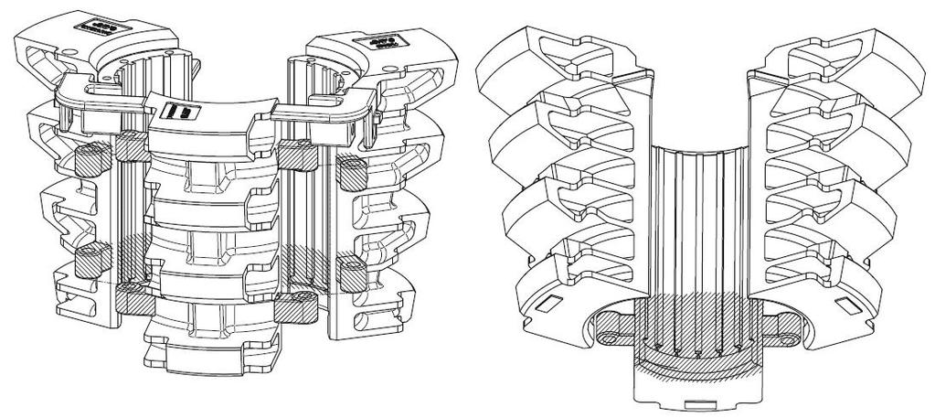
11 Main assemblies 4 3 The power slips consist of the following main parts: 1. Body 2. Door 3. Slip Assembly 4. Top Cover incl. Guide Plates 5. Pneumatic Assembly DESCRIPTION Improper / Unsafe Use The FPS 500 must only be used for the designated purpose. When using the FPS 500, the load of 500 sh tons must never be exceeded. Limited Warranty The warranty provided will be void if the Powerslip is either: a) repaired or serviced by a service facility which was not authorised by Blohm+Voss Oil Tools b) replacement parts not manufactured by Blohm+Voss Oil Tools are used c) modifications were made to the Powerslip which were not approved by Blohm+Voss Oil Tools Serial No. API License No. S W L 500 SH Tons P/N: F PS 500 S/N:XXXXX Size 7K 0039 B+V 11/12 4.1/2" Safe working load Part No. Date of manufacturer Manufacturer Identification The identification area clearly identifies the Powerslip area (manufacturer, type, material, part number, serial number, date of manufacture). It is important to keep this information ready for the purpose of servicing and repair work. 11
12 DESCRIPTION Technical Data Rotary table: 37.5 Maximum allowable working load 500 sh tons Pipe size range (i.e. Drill pipe, casing, tubing and drill collar) 4.1/2 to 14 Weight Power Slip w/o Guide Plates and Slips Working pressure Maximum allowed pressure Recommended Flow rate Temperature working range ambient Pneumatic lines for operation Pneumatic line for feedback 2100 kg (4630 Lb) Min. 7 bar (100 Psi) up to 8,6 bar (125 Psi) 10 bar (145 Psi) 6,8 m3/min (1,8 Gpm) - 20 C to + 60 C - 4 F to 104 F A + B C 12

13 Options DESCRIPTION Standard cover plate Bit Breaker cover plate Cable penetration cover plate 13


14 31 Main Dimension DESCRIPTION 7, , , , , FPS500 for National ,92 45, FPS500 for Wirth FPS500 for Emsco ,32 39, ,32 39,

15 Insert Carrier grip Length Drill Pipe and Casing DESCRIPTION 15
16 DESCRIPTION 16
17 COMMISSIONING COMMISIONING 17
18 2. COMMISSIONING Commissioning FPS 500 Blohm + Voss strongly recommends to accomplish the Flush Power Slip commissioning with the Blohm + Voss Commissioning Service. Read manual before first use! OK o Operating personnel is aware of all danger that depends on handling the B+V tool (see manual first)! COMMISIONING Prior to use of the Blohm+Voss Power Slip following checks must be carried out : Scope of supply OK o Cross check all delivered parts. Pneumatic Characteristics OK o OK o Operating pressure Min. 7 bar (100 psi) up to 10 bar (145 psi) Recommended flow rate 6,8 m3/min (1,8 Gpm) OK o Lubricator, air regulator and filter installed. Check and Lubrication OK o OK o Check for correct seating of Door Hinge Pins Apply grease to all greasing Points (see manual ) until grease is visibly coming out of the bores 18
19 INSTALLATION INSTALLATION 19


. The Control Unit has three ports (S1, S2, S3) that lead to the driller cabin.")
20 3. INSTALLATION Lifting and transport WARNING: Lift the Power Slip on the lifting ears only. WARNING: Wear your personal protection equipment at all times. Pneumatic System WARNING: Before start of work wear your personal protection equipment. Especially leak oil under pressure can cause severe personal injury to the eyes. Pneumatic connections INSTALLATION Purging air The FPS has three connection (A,B,C) on top. Conection A: Pneumatic Air pressure at connection "A" set the slips. Connection B: Pneumatic Air pressure at connection "B" raise the slips. Connection C: When the slips are completely set via connection "A", connection "C" applies a pneumatic pressure of approximately working pressure. Lines A,B and C connect the FPS to the Control Unit (optional equipment). The Control Unit has three ports (S1, S2, S3) that lead to the driller cabin. Two other ports (T, P) connect the Control Unit to the pneumatic ring or the pneumatic power unit. Lifting eyes C pneumatic connections B A Lifting Traverse 20

21 Schematic connection / control diagram DRILLER CABIN (supplied by others) S1 S2 S3 Tank line M 3/8" F P pneumatic pressure 3/8" F M T Control Unit (optional) A B C NOTE: - B + V does not supply electrical cable outside of the control unit and does not supply installation of electrical cable. - If FPS or Control Unit is delivered without Hook Up Kit, then B+V supplies complete couplings (both male and female) with outside thread for connection (see table for different thread sizes) M F 3/8" 3/8" F M 1/4" F M Pressure: Pneumatic pressure: 7-10 bar ( psi) M 3/8" F 3/8" F M M 1/4" F INSTALLATION Legend A: Slips down B: Slips up C: Feedback signal T: Return line P: Pressure line T: Return S1: Signal to set the Slips S2: Signal to raise the Slips S3: Feedback Signal (when Slip properly set) Electric connection S1: 24V DC, (cable gland: cable diameter 4-9mm) S2: 24V DC, (cable gland: cable diameter 4-9mm) S3: max.250v, (cable gland: cable diameter 4-9mm) Connection Thread sizes A, B, P, T G 1/4" C G 1/4" Pneumatic line Electric line M: Male coupling F: Female Coupling 21
22 Checking Guide Plates Before installation, inspect the body guide plate, door guide and top guard guide plate on the power slip. Ensure that the used guide plates are properly secured and that the correct guide plate size is installed. Also ensure that the slips and inserts have the correct size. Body Guide Plate 6 5/8"- 7 " 6 5/8"- 7 " Size Door Guide Plate INSTALLATION Upper Guard Guide Plate / Half 6 5/8"- 7 " Size 22
.")


.")
23 1 2 Changing Slips Raise the slips, suspend them from a line and remove the cotter pin (1). Pull out the two retainer pin assemblies (2). Install the slip size desired, and then reinstall the retainer pin assemblies. Changing Slips 1 2 Changing Inserts Remove the retainer screws, washer and the insert retainer plates (1). Pull out the inserts and replace them with the required size (2). When reinstalling inserts, make sure the insert slots are greased and the inserts teeth are pointing upward. INSTALLATION Changing inserts 23
24 Installation FPS 500 Basically the FPS 500 has to be installed as shown in the manual Before installation into rotary table make sure, that the proper RT-Adapter is installed to the FPS 500. OK o OK o OK o OK o Make sure the required Guide Plates are installed before first use The Guide Plates are fixed with the screws Cover is closed Door is closed INSTALLATION Pneumatic Connections OK o OK o OK o OK o Function test FPS 500 is installed into Rotary Table Control Unit connected to Pneumatic Power Unit (PPU) FPS 500 connected to Control Unit All Pneumatic Lines are connected There are two possibilities to carry out the function test: 1. FPS 500 standing on the floor WARNING: Do not carry out the function test with the door opened 2. FPS 500 installed into the rotary table OK o Slip set OK o Feedback signal: Slips are Set OK o Slip raised 24
25 OPERATIONS OPERATIONS 25
26 4. OPERATIONS WARNING: Keep away from the FPS while operation. WARNING: Never raise the slips when the pipe load is still suspended by the slips. Safety 1. Make sure that ALL pneumatic lines are isolated before any work is carried out in the FPS. 2. It is recommended to have the FPS operated by the driller. 3. For smooth operation, it is recommended to slightly lower the pipe with the elevator while setting the FPS slips. 4. For smooth operation, it is recommended to slightly raise the pipe with the elevator while releasing the FPS slips. 5. The rotary locks in the outside of the FPS may only be needed on semisubmersible rigs or while floating in pipe when there is a chance the FPS could come out of the rotary table. Operation OPERATIONS 1. Check that slips are set on correct section of the pipe. Set the FPS before releasing the elevator. The slips are completely set, when the feedback signal is given. 2. When the rotary table and the FPS have to be rotated, always uncouple the quick disconnects on the FPS prior to rotation. 3. Place the FPS in the rotary table using all 4 lifting eyes and the lifting bracket. 4. Connect all pneumatic equipment and check for correct function of the tool. 5. With the pipe string being suspended by the FPS slips, make up or break the upper stand or joint, and handle it. 6. Pick up the weight of the pipe string with the elevator, before raising the FPS slips. 7. Set the slips of the FPS and then release the elevator. Removing the FPS when pipe is in the hole WARNING: Lift the FPS out of the rotary table ONLY with the 4 way lifting sling with the lifting bracket. Removing the FPS from drill pipe (in rotary) 1. Take the load from the slips 2. Raise the slips 3. Depressurize the FPS hook up hoses 4. Remove one hinge pin from the FPS door 5. Lift the FPS out of the rotary table by using the four way lifting bracket 6. Open the FPS door 7. Move the FPS away from the pipe / well center Connecting and disconnecting of the pneumatic hoses WARNING: Be careful when disconnecting pneumatic hoses. Make sure that there is no pressure on the hoses and the weight of the string cannot generate pressure Dis-connection hoses in slips up position 1. Set FPS in neutral position 2. Disconnect Quick Disconnects. 26
27 Handling the slip assembly during operation WARNING: The slip assembly should never be raised under load. WARNING: If the slip assembly is set the FPS can bear the load of the pipe. WARNING: Before raising the slip assembly, make sure that the elevator is closed and suspends the weight of the pipe. WARNING: Never operate the Slip Assembly with the door open. WARNING: Never set the Slips as long as the Elevator/Top Drive is still lifting or lowering the pipe. WARNING: With the power slip installed in the rotary there is the risk of small parts falling into the Power Slip or bore hole. WARNING: There is a risk of injury (danger of tripping) when the FPS top covers are open. OPERATIONS 27
. 2.")
 by using a crane. 4. Open the Door. 5.")
28 (Emergency) opening the door Move Slip to upper position 1. Open the Cover by using the handle (1). 2. Remove the cotter pin (2) and pin (3). Cover 3. Pull out the hinge pin (4) by using a crane. 4. Open the Door. 5. To close the door again follow the same operation steps backwards. Handle (1) OPERATIONS (2) (4) (3) 28
29 MAINTENANCE & INSPECTION MAINTENANCE & INSPECTION 29


30 5. Maintenance and Inspection General If cracks, excessive wear etc. is recognised, contact Blohm + Voss Oil Tools or an authorised service company. Weldings of the castings should be done only by Blohm + Voss Oil Tools or an authorised service company in according to Blohm+Voss welding procedure. A regular preventative maintenance program should be established for all elevators. These written maintenance procedures should be given to the crew or maintenance personnel. Back of the Slips WARNING: For Service and Maintenance disconnect the pneumatic lines. Daily Lubrication When the tool is in use, the following lubrication procedure should be performed daily, or as inspection indicates: 1. Lubricate the bowl and back of the slips with heavy grease (See figure). 2. Lubricate the door hinge pins. 3. Grease the left and right yoke. (1) (1) (1) MAINTENANCE & INSPECTION
:")
31 Grease daily All greasing points, which are labelled Grease Daily, must be greased at least once a day. It can be necessary to carry this out more often depending on use. Grease quality In order to achieve efficient greasing even at different environmental temperatures, we recommend the following grease types should be used (obtainable from Blohm + Voss Oil Tools): Low-Viscosity grease Type AVIATICON Grease XRF NLGI 0 Alternatively; use EP gear lubricating grease for greasing non-oil tight gear trains NESSOS SF0 NLGI 0 DIN GPOF-25 DIN GPOF-25 For higher ambient temperature up to 30 Celsius / 86 Fahrenheit we recommend to use NLGI 2 Recommended grease gun MAINTENANCE & INSPECTION 31
32 Inspection categories acc. to API RP 8B MAINTENANCE & INSPECTION Category I This category involves observing the equipment during operation for indications of inadequate performance. When in use, equipment shall be visually inspected on a daily basis for cracks, loose fits or connections, elongation of part, and other signs of wear, corrosion or overloading. Any parts found to show cracks, excessive wear, etc., shall be removed from service for further examination. The equipment shall be visually inspected by a person knowledgeable in that equipment and its function. Category II This is Category I inspection plus further inspection for corrosion, deformation, loose or missing components, deterioration, proper lubrication, visible external cracks, and adjustment. Category II may involve some disassembly to access specific components and to identify wear that exceeds the allowable tolerances. Category III This is Category II inspection plus further inspection, which should include NDT of critical areas and may involve some disassembly to access specific components and to identify wear that exceeds the allowable tolerances. Prior to inspection, all foreign material such as dirt, paint, grease, oil, scale, etc. shall be removed from the concerned parts by a suitable method (e.g. paint-stripping, steam-cleaning, grit-blasting). Category IV This is Category III inspection plus further inspection for which the equipment is disassembled to the extent necessary to conduct NDT of all primary-load-carrying components. Equipment shall be: disassembled in a suitableequipped facility to the extent necessary to permit full inspection of all primary-loadcarrying components and other components that are critical to the equipment. inspected for excessive wear, cracks, flaws and deformation. Procedure: Corrections shall be made in accordance with the manufacturer s recommendations. Prior to inspection, all foreign material such as dirt, paint, grease, oil, scale, etc. shall be removed from the concerned parts by a suitable method (e.g. paintstripping, steam-cleaning, gritblasting) Frequency Periodic inspection The recommended schedule for inspection of all kind of Power Slips: Ongoin: I Weekly: II 6 Monthly: III 1 Year: IV The recommended frequencies apply for equipment in use during the specified period. The inspection frequencies are only recommendations. The schedule of inspection heavily depends on the following factors: environment load cycles regulatory requirements operating time testing repairs re manufacture Non-periodic inspection A complete, on-job, shut-down inspection equivalent to the periodical Category III or Category IV should be made before (if anticipated) and after critical jobs (e.g., running heavy casing / drill strings, jarring, pulling on stuck pipes and/or operating at extreme low temperatures) <-20 C (<-4 F). Inspection A thorough inspection should be carried out periodically (every 3 months) or as special circumstances may require. Before starting an inspection disconnect any hydraulic/pneumatic system and remove all foreign materials (dirt, paint, grease Oil, scale, etc.) from surface by a suitable method. After a field inspection, it is advisable to record the extent of testing and testing results. Conduct the periodic or critical load inspection in the field by the crew with the supervisor. If cracks, excessive wear etc. is recognized, contact Blohm + Voss Oil Tools or an authorized service company. Inspection of Hydraulic/ Pneumatic System Check for leakage every day. Should internal or external leakage reach an unacceptable high level, contact Blohm + Voss Oil Tools or an authorized service company. Critical Load Inspection Critical loads may occur. For example: impact loads such as jarring, pulling on stuck pipe, etc. If critical loads occurred unexpectedly, conduct the inspection immediately. 32
33 Dismantling Inspection Generally, when the equipment returns to base, warehouse, etc. Carry out the Tool inspection, immediately. Furthermore, control it prior to its being sent on the next job. The Tool should be dismantled and inspected in a suitably equipped facility for excessive wear, cracks, flaws or deformations. Corrections should be made in accordance with recommendations which can be obtained from Blohm + Voss Oil Tools. Weldings at the castings should be done only by Blohm + Voss Oil Tools or an authorized service company in according to Blohm+Voss welding procedure. When need is shown in a field inspection, dismantle the Tool and arrange an inspection in a suitably equipped facility. Springs should be carefully visually inspected for excessive wear and obvious weakness. MAINTENANCE & INSPECTION 33
34 Inspection check lists CHECK LIST FRONT PAGE TYPE OF EQUIPMENT SERIAL NUMBER PART NUMBER SUPERVISOR DATE OF INSPECTION INSPECTION CATEGORY PLACE OF INSPECTION MAINTENANCE & INSPECTION 34
35 Check List Category I (During operation - Flush Power Slip is placed in the Rotary Table, Cover is closed) GENERAL DESCRIPTION CHECKED SIGNATURE 1 Complete front page of check list for the records OK 2 Check for correct size of slips and guide plates OK 3 Check correct function of Slips OK 4 Check function of feedback signal (slips set / raised) OK Remarks CHECK FOR LOOSE ITEMS, ESPECIALLY FOR: DESCRIPTION CHECKED SIGNATURE 1 Hinges and bolts of cover assembly OK 2 Cover Locking device OK 3 Fixation of guide plates OK 4 Top cover screws OK 5 Lifting eyes for Power Slip OK Remarks CHECK FOR CRACKS, ELONGATION, DAMAGE AND CORROSION, ESPECIALLY FOR: DESCRIPTION CHECKED SIGNATURE 1 Power Slip Body Hinges of Cover Assembly OK 2 Hinges and bolts of cover assembly OK 3 Cover Locking device OK 4 Guide plates OK 5 Lifting eyes for Power Slip OK Remarks MAINTENANCE & INSPECTION 35
36 CHECK FOR WEAR, ESPECIALLY FOR: DESCRIPTION CHECKED SIGNATURE Pneumatic guide plates: Check wear at inside surface 1 Replace the guide if wear is more than 10 mm at the bevel inside the guide plate. OK Remarks HYDRAULIC DESCRIPTION CHECKED SIGNATURE 1 Check for loose fittings, pipes, valves OK 2 Check for pneumatic leaks (hoses, valves and cylinders) OK 3 Check condition of pneumatic couplings and connection hoses OK Remarks MAINTENANCE & INSPECTION SUPERVISOR DATE 36
37 Check List Category II (Flush Power Slip is out of Rotary Table, Cover is open) GENERAL DESCRIPTION CHECKED SIGNATURE 1 Complete front page of check list for the records OK 2 Check for correct size of slips and guide plates OK 3 Check correct function of Slips: Set Slips cycle: 1. Set Slips OK 2. Raise Slips 4 Check function of feedback signals (slips set / raised) OK Remarks CHECK FOR LOOSE ITEMS, ESPECIALLY FOR: DESCRIPTION CHECKED SIGNATURE 1 Hinges and bolts of cover assembly OK 2 Cover Locking device OK 3 Fixation of guide plates OK 4 Top cover screws OK 5 Lifting eyes for Flush Power Slip OK 6 Transportation beam OK 7 Fixation of Pneumatic Cylinder OK 8 Fixation of Pneumatic Hoses below Cover Assembly OK Remarks CHECK FOR CRACKS, ELONGATION, DAMAGE AND CORROSION, ESPECIALLY FOR: DESCRIPTION CHECKED SIGNATURE 1 Flush Power Slip Body Hinges of Pneumatic Cylinder OK 2 Flush Power Slip Body Hinges of Cover Assembly OK 3 Flush Power Slip Body Outside Body surface / contact areas to rotary table OK 4 Hinges and bolts of cover assembly OK 5 Cover Locking device OK 6 Guide plates OK 7 Lifting eyes for Flush Power Slip OK 8 Transportation beam OK 9 Check condition of Insert Retainer Plates and Screws OK 10 Check teeth of insert dies OK 11 Check load recess at bottom OK 12 Slip Assembly Hinges for Pneumatic Cylinder OK 13 Slip Assembly Hinges and bolts between Center/Left/Right-segments OK Remarks MAINTENANCE & INSPECTION 37
38 CHECK FOR WEAR, ESPECIALLY FOR: DESCRIPTION Pneumatic guide plates: Check wear at inside surface Replace the guide if wear is more than 10 mm at the bevel inside the guide 1 plate CHECKED SIGNATURE OK 2 Check wear of insert dies OK Remarks GREASING DESCRIPTION CHECKED SIGNATURE 1 Check that grease system and grease points get grease to all needed areas (as far as observable) especially for: OK 2 Slip Assembly back side OK 3 Cover Assembly Locking Device OK 4 Feedback signal OK 5 Hinges at Door and Body OK Remarks HYDRAULIC DESCRIPTION CHECKED SIGNATURE 1 Check for loose fittings, pipes, valves OK 2 Check for pneumatic leaks of all hoses, valves and cylinders OK 3 Check condition of pneumatic couplings and connection hoses OK 4 Check pneumatic fittings and hoses in rotary table OK Remarks MAINTENANCE & INSPECTION REMARKS SUPERVISOR DATE 38
39 Check List Category III (Flush Power Slip is out of Rotary Table, Cover is open, Slip Assembly disassembled) USE CHECK LIST OF CATEGORY II WITH FOLLOWING ADDITIONAL ITEMS: DESCRIPTION CHECKED SIGNATURE GENERAL 1 Check completeness and condition of warning plates and labels OK 2 Check condition of identification plate (serial number, part number, date of manufacture etc.) OK 3 Clean tool thoroughly OK NDT - INSPECTION NDT all critical areas with die penetrant OK REMARKS MAINTENANCE & INSPECTION SUPERVISOR DATE 39
40 Check List Category IV (Flush Power Slip is out of Rotary Table, Cover is open, Slip Assembly disassembled) USE CHECK LIST OF CATEGORY III WITH FOLLOWING ADDITIONAL ITEMS: HYDRAULICS CHECKED SIGNATURE 1 Change all pneumatic hoses and fittings OK 2 Check condition of pneumatic valves and replace if necessary OK 3 Check condition of pneumatic pipes and replace if necessary OK REMARKS MAINTENANCE & INSPECTION SUPERVISOR DATE 40
41 Wear data criteria Bore of Door and Body Hinges FPS 500 Dimension worn max: Dimension new max: Door Hinge Pin Hinge pin min dia new: Hinge pin min dia worn min: Dim. A 81,120 mm 80,106 mm 79,80 mm 79,80 mm Dim. A Door/Body Hinge dimensions MAINTENANCE & INSPECTION Door/body hinge 41


42 Critical Areas Critical Areas Body Critical Areas Door and Hinge Pin Critical Areas Slips MAINTENANCE & INSPECTION 42
43 Critical area drawings of lifting eyes MAINTENANCE & INSPECTION 43
44 Handling, storage and transport Storage Storage of the tool requires the following measures to be taken: Ensure the tool is protected from water ingress Ensure the tool is stored in such a way, that personnel cannot be wounded by moving parts or sharp edges. If needed, secure the tool with ropes or otherwise in order to protect it from sliding due to ship movements. Short term storage after use and less then 3 months Preserve the tool: Grease all blank surfaces with grease: Cylinders Preserve all other blank surfaces with Tectyl Type 864 or equivalent Storage: Store in a dry environment with humidity max 80%. Commissioning: Not needed Long term storage over 3 months MAINTENANCE & INSPECTION Preserve the tool: Grease all blank surfaces with grease: Cylinders Preserve all other blank surfaces with Tectyl Type 864 or equivalent Storage: Store in a dry environment with humidity max 80% Commissioning: As per procedure in the User Manual Handling Lift the tool by its lifting ears only. Transport When the tool is in it s original crate, use a fork lift for lifting the crate only. The weight of the tool is indicated on the identification area of the tool, and also on its original transporting crate. 44
45 SIZE COMPONENTS SIZE COMPONENTS 45
46 6. SIZE COMPONENTS Slips, Inserts, Guide Plates API Slip Assemblies Inserts Elevator Guide Plates Spider Guide Plates Size Pipe Size P/N P/N-Qty 5.1/2 Guide P/N 4.1/ / Screw P/N Washer P/N Guide P/N Screw P/N Washer P/N Diameter ø ø /8 9.5/8 10.3/4 11.3/ / ø / / ø / ø / / ø / / / ø / / ø / ø / / ø ø 385 SIZE COMPONENTS 46
47 DRAWINGS & SPARE PARTS 47 DRAWINGS & SPARE PARTS
48 7. DRAWINGS AND SPARE PARTS N-AIR FPS 500 for National RT Feedback valve DRAWINGS & SPARE PARTS
49 N-AIR Parts list Pos. Qty. Part No. Description Pos. Qty. Part No. Description BF Body Safety Sheet BF Door Washer Yoke, left Washer Yoke, right Washer Hinge Pin Washer Cylinder Mounting Washer Cylinder Flange Warning Sign Don t touch Cylinder Pin Technical Support Locking Device Warning Sign Blohm + Voss Locking Mechanismus Warning Sign Hands Clevis Pin with Head Warning Sign Squeeze Danger Yoke Pivot Pin Warning Sign Grease Daily Cylinder Pin Lubrication Warning Slip Retainer Pin Assembly Slip Stop Pin Cover National Cover Plate Feedback valve Assembly AIR Pneumatic Assembly Contributor Block Pneumatic Cylinder Feedback Cover Adapter National 24 1 Table Sheet 61 Slip Assembly Spider Plate Assembly Hose Protection Bushing Lifting Eye Screw Screw Screw Screw Screw Screw Hexagon Screw Screw Cylinder Screw Sealing Screw Blind Screw Nut Grease Fitting Grease Fitting Cotter Pin Cotter Pin Grease Nozzle Grease Nozzle Safety Sheet DRAWINGS & SPARE PARTS 49
50 Slip Retainer Pin Assembly Parts list Pos. Qty Part. No. Description Retainer Pin Roller Retainer Ring Grease Nipple DRAWINGS & SPARE PARTS 50
51 Feedback valve Assembly A Slips raised SCHNITT A-A Slips set Parts list Pos. Qty. Part no. Description Mounting Plate Feedback sleeve Feedback Pin Feedback Pin Overload Spring Screw Nut Washer DRAWINGS & SPARE PARTS A acivtated by yoke 95 51
52 Locking Mechanism Parts list Pos. Qty Part. No. Description Locking Pin Handle Grease Fitting DRAWINGS & SPARE PARTS 52

53 Bit Breaker Adapter Plate Cover Plate for Bit Breaker Plate Cover Plate for Cable Penetration DRAWINGS & SPARE PARTS 53

54 Guide Plates for Cable Penetration Parts list Guide Plate Assembly for Cable Penetration Part-No. Pipe Size Weight (Kg) /2 35, /2 34, /8-7 30, /8-7.3/4 36, / /8-9.7/8 25, /4 23, /4-11.7/8 21, /4 22, /8-13.5/8 19, ,4 DRAWINGS & SPARE PARTS 54

55 Upper Guard Guide Plates / Spider Parts list Upper Guard Plates / Spider Part no. Pipe Size / / / /8-7.3/ / /8-9.7/ / /4-11.7/ / /8-13.5/ DRAWINGS & SPARE PARTS 55
56 Guide Plates Assembly / Elevator (Body Guide Plate and Door Guide Plate) Body Guide Plate 6 5/8"- 7 " 6 5/8"- 7 " Size Door Guide Plate Parts list Guide Plates Assembly / Elevator Part no. Description Pipe size PN Body Plate PN Door Plate Guide Plate Ass. 4.1/ Guide Plate Ass / Guide Plate Ass. 6.5/ Guide Plate Ass. 7.5/8-7.3/ Guide Plate Ass. 8.5/ Guide Plate Ass. 9.5/8-9.7/ Door Guide Plate 10.3/ Door Guide Plate 11.3/4-11.7/ Door Guide Plate 12.3/ Door Guide Plate 13.3/ Door Guide Plate DRAWINGS & SPARE PARTS 56
57 Slip Assembly Parts List Slip Assembly Pos. Qty Part no. Part no. Part no. Description 5.1/2 x4.1/2 PN /2 x5 PN /2 x5.1/2 PN Center Slip Segment 5.1/ Left Slip Segment 5.1/ Right Slip Segment 5.1/ Hinge Pin Hinge Pin Cotter Spring Inserts Updated Insert Retainer Cap Screw Lock Washer DRAWINGS & SPARE PARTS 57
58 Pos. Qty Part no. Part no. Part no. Part no. Description 7.5/8 x6.5/8 PN /8 x7 PN /8 x7.3/4 PN /8 x7.5/8 PN Center Slip Segment 7.5/ Left Slip Segment 7.5/ Right Slip Segment 7.5/ Hinge Pin Hinge Pin Cotter Spring Inserts Upgrated Insert Retainer Cap Screw Lock Washer Pos. Qty Part no. Part no. Description 9.5/8 x8.5/8 PN /8 x9.5/8 PN Center Slip Segment 9.5/ Left Slip Segment 9.5/ Right Slip Segment 9.5/ Hinge Pin Hinge Pin Cotter Spring Inserts Upgrated Insert Retainer Cap Screw Lock Washer Pos. Qty Part no. Part no. Part no. Description 10./4 x9.7/8 PN /4 x9.5/8 PN /4 x10.3/4 PN Center Slip Segment 9.5/ Left Slip Segment 9.5/ Right Slip Segment 9.5/ Hinge Pin Hinge Pin Cotter Spring Inserts Upgrated Insert Retainer Cap Screw Lock Washer DRAWINGS & SPARE PARTS 58
59 Pos. Qty Part no. Part no. Part no. Description 11.3/4 x10.3/4 PN /4 x11.7/8 PN /4 x11.3/4 PN Center Slip Segment 11.3/ Left Slip Segment 11.3/ Right Slip Segment 11.3/ Hinge Pin Hinge Pin Cotter Spring Inserts Upgrated Insert Retainer Cap Screw Lock Washer Pos. Qty Part no. Part no. Description 13.3/8 x12.3/4 PN /8 x13.3/8 PN Center Slip Segment 13.3/ Left Slip Segment 13.3/ Right Slip Segment 13.3/ Hinge Pin Hinge Pin Cotter Spring Inserts Upgrated Insert Retainer Cap Screw Lock Washer Pos. Qty Part no. Part no. Part no. Part no. Description 14 x14 PN x13.5/8 PN x13.3/8 PN x12.3/4 PN Center Slip Segment Left Slip Segment Right Slip Segment Hinge Pin Hinge Pin Cotter Spring Inserts Upgrated Insert Retainer Cap Screw Lock Washer DRAWINGS & SPARE PARTS 59
60 AIR Pneumatic Assembly Cylinder PN Cylinder PN FPS X X Pneumatic Block PN A1 C1 B1 C A B DRAWINGS & SPARE PARTS 60
61 AIR Parts List Pos. Quantity Part no. Description Throttle Back pressure valve Directional control valve AIR-40 Hydraulic Hose Assembly for FPS 500-AIR Pneumatic Hose Pneumatic Hose Pneumatic Hose Pneumatic Hose Pneumatic Hose Pneumatic Hose Pneumatic Hose Pneumatic Hose AIR-A Hose Assembly A AIR-B Hose Assembly B AIR-C Hose Assembly C Reducing nipple T-Connector T-Connector L-Connection Straight fitting Elbow Fitting Connector socket Fitting Coupling Clutch hose coupling DRAWINGS & SPARE PARTS 61
Blohm+Voss Pipe Handling Equipment Special Link Connector Technical Documentation Original instructions
 Blohm+Voss Pipe Handling Equipment Special Link Connector Technical Documentation Original instructions Manual PN 554106-D Rev. 002, May 2012 Blohm + Voss Oil Tools 1 GENERAL INFORMATION Warnings and Note
Blohm+Voss Pipe Handling Equipment Safety Clamps Type C and T Technical Documentation Original Instructions
 Blohm+Voss Pipe Handling Equipment Safety Clamps Type C and T Technical Documentation Original Instructions Manual PN 88003-D Rev. 010, August 2013 Blohm + Voss is a trademark of Blohm + Voss Shipyards
Blohm + Voss Pipe Handling Equipment VES-CL Center Latch Elevator, Manual Operated c/w Bushing Technical Documentation Original Instructions
 Blohm + Voss Pipe Handling Equipment VES-CL 150-1000 Center Latch Elevator, Manual Operated c/w Bushing Technical Documentation Original Instructions Manual PN 611000-Y-D Rev 003 February 2012 Blohm +
TECHNICAL DOCUMENTATION
 Read before first use! VES-CL-1000 Elevator Hydraulically Operated Part No. 611000-Y-H Blohm + Voss Oil Tools Hermann-Blohm-Straße 2 20457 Hamburg Germany Telephone ++49 (0)40/3119-1826/1162 Fax ++49 (0)40/3119-8194
Blohm + Voss Pipe Handling Equipment BVE / BVS 750 Frame 1 air operated 4.1/2 14 Technical Documentation Original Instructions
 Blohm + Voss Pipe Handling Equipment BVE / BVS 750 Frame 1 air operated 4.1/2 14 Technical Documentation Original Instructions Manual PN 710000-Y-A-D Rev 004, February 2012 Blohm + Voss Oil Tools 1 GENERAL
Blohm + Voss Pipe Handling Equipment SDS Side Door Elevators 65, 100, 150, 250, 350 & 500 tons Technical Documentation Original Instructions
 Blohm + Voss Pipe Handling Equipment SDS Side Door Elevators 65, 100, 150, 250, 350 & 500 tons Technical Documentation Original Instructions Manual PN 641020-Y-BC-D Rev 013, Mai 2013 Blohm + Voss Oil Tools
Blohm + Voss Oil Tools
 Blohm + Voss Pipe Handling Equipment Rotary Hand Slips: RSM / RSX / LRS Drill Collar Slips: DCS / DCM / DCL Casing Slips: CSL / CSC Technical Documentation Original Instructions Manual PN 83500-D Rev 008,
Blohm + Voss Oil Tools
 Blohm+Voss Pipe Handling Equipment Hydraulic Operated Elevator/Spider BVE / BVS 500 PN 752000-Y-H-VC 4.1/2-14 Technical Documentation Original Instructions Manual PN 752000-Y-H-VC-D Rev 001, February 2012
Blohm+Voss. BVE / BVS /8 7.5/8 250 metric tons
 Blohm+Voss BVE / BVS 250 2.3/8 7.5/8 250 metric tons Part-No. 725000 READ THESE INSTRUCTIONS BEFORE USE! Blohm+Voss Oil Tools Hermann-Blohm-Straße 2 20457 Hamburg Germany Telephone ++49 (0)40/3119-1826/1162
Blohm + Voss Pipe Handling Equipment ABVC-200 Sliptype Elevator Technical Documentation Original Instructions
 Blohm + Voss Pipe Handling Equipment ABVC-200 Sliptype Elevator Technical Documentation Original Instructions Blohm + Voss Oil Tools Manual PN 672600-Y-D Rev 003, February 2012 1 GENERAL INFORMATION Warnings
Blohm+Voss BVE/S-750 Elevator/Spider 4 ½ 14 Pipe Range Diameter
 Read before first use! Blohm+Voss BVE/S-750 Elevator/Spider 4 ½ 14 Pipe Range Diameter Part No. 710000-Y-H hydraulic version Blohm + Voss Oil Tools Hermann-Blohm-Straße 2 20457 Hamburg Germany Telephone
Blohm + Voss Oil Tools
 Blohm+Voss Pipe Handling Equipment VES-HCL 350 Elevator Hydraulically Operated Part no. 63000-Y-H-F (with closing signal) Technical Documentation Original Instructions Manual PN 63000-Y-H-F-D Rev 005 valid
Blohm + Voss B+V hinged Adapter
 Blohm + Voss B+V hinged Adapter 49 /2 to 37 /2 for RT National Inspection and maintenance procedure Part No. 55320 Blohm+Voss Oil Tools Hermann-Blohm-Straße 2 20457 Hamburg Germany Telephone ++49 (0)40/39-826/62
CONTROL UNIT FOR POWER SLIPS PN:
 CONTROL UNIT FOR POWER SLIPS PN: 757105 Blohm + Voss Oiltools Herrmann-Blohm-Strasse 2 20457 Hamburg Germany Telephone ++49 (0)40/3119-1826/1162 Fax ++49 (0)40/3119-3305 Revision 001, February 2012 All
BVM Corporation TYPE MS TONG 6,500 FT/LBS. TORQUE
 Page 1 BVM Corporation TYPE MS TONG 6,500 FT/LBS. TORQUE Part number: Serial Number: BVM CORPORTION TYPE MS TONG 6,500 FT/LBS. TORQUE WRNING: Manual tongs which have experienced excessive wear or are found
Blohm + Voss Oil Tools, LLC GraySpin Mark 40 Hydraulic Drill Pipe Spinner With and without Hydraulic Lift Technical Documentation
 Blohm + Voss Oil Tools, LLC GraySpin Mark 40 Hydraulic Drill Pipe Spinner With and without Hydraulic Lift Technical Documentation 1 GENERAL INFORMATION Warnings and Notes WARNING: A WARNING INDICATES A
Before equipment use, please read this operation manual carefully. Serial Number: Date Purchased:
 Pushed & Geared Trolleys OPERATION MANUAL This operation manual is intended as an instruction manual for trained personnel who are in charge of installation, maintenance, repair etc. Before equipment use,
Pipe Handling Equipment
 Pipe Handling Equipment Blohm+Voss Repair GmbH Oil Tool Division Hermann-Blohm-Straße 2 20457 Hamburg, Germany Phone: +49-40-31 19-81 42 Fax: +49-40-31 19-34 00 E-mail: info@blohmvoss-oiltools.com www.blohmvoss-oiltools.com
Top Drive System Installation and Commissioning Manual
 TDS-1000A Top Drive System Installation and Commissioning Manual SM01040 General Information Conventions.............................. 1-3 Notes, Cautions, and Warnings......................... 1-3 Illustrations.........................................
Blohm + Voss Oil Tools Circular Buttons, Inserts and Dies Catalog
 Blohm + Voss Oil Tools Circular Buttons, Inserts and Dies Catalog A company of ThyssenKrupp Marine Systems Blohm + Voss Repair Blohm + Voss Oil Tools General Information Brochure Contents INSERTS: DIMENSIONS...
Safety Clamp Operation Manual
 TECHNICAL MANUAL Safety Clamp Operation Manual 2005-2016 Texas International Oilfield Tools, LTD. Published by Texas International Oilfield Tools, LTD, Engineering 14620 Henry Road. Houston, TX 77060 www.texasinternational.com
Innovative Landing String system for ultra-deep offshore
 Innovative Landing String system for ultra-deep offshore V. Flores, J.Franchi, S. Granger Vallourec Drilling Products A. Vierke, J. Grotherr Blohm+Voss Oil Tools Introduction Offshore industry trends:
Installation and Operation Manual
 1645 Lemonwood Dr. Santa Paula, CA 93060 USA Toll Free: 1 (800) 253-2363 Tel: 1 (805) 933-9970 rangerproducts.com Ranger Floor Jack Installation and Operation Manual Manual Revision B July 2017 Manual
Instruction Manual. Unique 7000 Series Aseptic - Manually Operated ESE02421-ENUS Original manual
 Instruction Manual Unique 7000 Series Aseptic - Manually Operated 2210-0042 ESE02421-ENUS1 2013-03 Original manual Table of contents The information herein is correct at the time of issue but may be subject
Safelift Overhead Runway Beams & Rolling Beam Cranes
 Operation & Maintenance Instructions Instructions for Safe Use Safelift Overhead Runway Beams & Rolling Beam Cranes Certification Safelift overhead runway beams and rolling beam cranes are lifting appliances
Keystone Butterfly valves ParaSeal Installation and maintenance instructions
 Before installation these instructions must be fully read and understood Please read these instructions carefully Hazard potentials: disregarding of instructions improper use of product insufficiently
Translation of the Original operating instructions Lifting device Z 70 /...
 Translation of the Original operating instructions Lifting device Z 70 /... Content 1. Lifting device / Correct use according to regulations 2. Basic principles 3. General information 4. Special remarks
MEYER-Rotating Fork Positioners are attachments used to transport loads and replace
 This MEYER-Attachment complies in every aspect to the EC-Safety Guidelines. The Certificate of Conformation / Declaration by the Manufacturer has been delivered with the attachment. The CE-Symbol can be
Type 3571 Pneumatic Actuator. Actuator areas: 27 in² 54 in² 116 in². Original instructions. Mounting and Operating Instructions EB 8820 EN
 Type 3571 Pneumatic Actuator Actuator areas: 27 in² 54 in² 116 in² Original instructions Mounting and Operating Instructions Edition April 2016 Note on these mounting and operating instructions These mounting
Operating & Maintenance Manual For Steam Conditioning Valve
 For Steam Conditioning Valve 1 Table of Contents 1.0 Introduction 3 2.0 Product description 3 3.0 Safety Instruction 4 4.0 Installation and Commissioning 5 5.0 Valve Disassembly 6 6.0 Maintenance 6 7.0
OPERATING MANUAL C-1350 CABLE PUSHER. Copyright 2003 by CBS Products (KT), Ltd
, Ltd") CBS Products (KT), Ltd, Pillings Road, Oakham, Rutland, LE15 6QF. UK Telephone: +44(0)1572723665 Fax: +44(0)1572 756006 E-Mail: sales@cbsproducts.com Website:www.cbsproducts.com OPERATING MANUAL C-1350
CBS Products (KT), Ltd, Pillings Road, Oakham, Rutland, LE15 6QF. UK Telephone: +44(0)1572723665 Fax: +44(0)1572 756006 E-Mail: sales@cbsproducts.com Website:www.cbsproducts.com OPERATING MANUAL C-1350
350 Ton Elevator Links/Link Extensions Operation Manual
 TECHNICAL MANUAL 350 Ton Elevator Links/Link Extensions Operation Manual 2005-2015 Texas International Oilfield Tools, LTD. Published by Texas International Oilfield Tools, LTD, Engineering 14620 Henry
Lineman s Hoist. Operating, Maintenance & Parts Manual. Follow all instructions and warnings for LMST680-2
 Lineman s Hoist LMST0- Operating, Maintenance & Parts Manual Lineman s Hoist Follow all instructions and warnings for inspecting, maintaining and operating this hoist. The use of any hoist presents some
Technical Description Edition 2007 Mounting, maintenance and repair of propshafts with flanged universal joints
 Technical Description Edition 2007 Mounting, maintenance and repair of propshafts with flanged universal joints 1. Recommendations Assembly, disassembly, maintenance and repair of propshafts should be
ROTARY TABLE With Master Bushing & Insert Bowl
 ROTARY TABLE With Master Bushing & Insert Bowl MODEL: RT-175 Serial No. Customer. II 2 G c T3 Cert.No. 28178-2008-CE-USA TCF No. MKP-RT1737 Mud King Product's Rotary Tables Are Manufactured For MKP Under
Package Contents Part A (3) I-Beam (1) Base (2) Other parts
 I-Beam (1) Base (2) Other parts") Page 1 Installation Instructions for 81245 Adjustable Height Gantry Crane 1-Ton Capacity Table of Contents Important Safety Information pg. 2 Specific Operation Warnings pg. 2 Main Parts of Product pg.
Page 1 Installation Instructions for 81245 Adjustable Height Gantry Crane 1-Ton Capacity Table of Contents Important Safety Information pg. 2 Specific Operation Warnings pg. 2 Main Parts of Product pg.
PAGE 1 OF 5 HEALTH, SAFETY & ENVIRONMENTAL MANUAL PROCEDURE: S360 Overhead Cranes & Lifts Procedure REV 4.0 8/14/2012
 PAGE 1 OF 5 PURPOSE: OVERHEAD CRANES AND LIFTS PROCEDURE The purpose of this procedure is to define the safety and training requirements for use of overhead cranes and lifts. Procedure: Definitions Designated
Keystone Figure 85/86 Check valves Installation and Maintenance Instructions
 Please read these instructions carefully 1.3 Handling 1.3.1 Packed valves Lifting and handling of the packed valves in crates should be carried out by appropriate lifting equipment. If a fork lift truck
50 TONNE HYDRAULIC PRESS MODEL NO: CSA50FP
 50 TONNE HYDRAULIC PRESS MODEL NO: CSA50FP PART NO: 7615202 OPERATION & MAINTENANCE INSTRUCTIONS WARNING: Read these instructions before using the press GC0516 INTRODUCTION Thank you for purchasing this
RENFROE. WARNING: Before putting tool in service, take to your immediate supervisor.
 WARNING: Before putting tool in service, take to your immediate supervisor. RENFROE Model NM Clamp Application, Operation and Maintenance Manual OM 211-NM Operators Manual This Operator s Manual covers
INSTRUCTION MANUAL. Pacific Self-locking Beam Trolleys Pacific Adjustable Angle Clamps Pacific Top Girder Clamps
 INSTRUCTION MANUAL Pacific Self-locking Beam Trolleys Pacific Adjustable Angle Clamps Pacific Top Girder Clamps IMPORTANT Please read this instruction manual before using these products. This manual contains
Butterfly valves Figure 56 Installation & Maintenance Instructions
 KEYSTONE Please read these instructions carefully This symbol indicates important messages and safety instructions. Hazard potentials: disregarding of instructions improper use of product insufficiently
SuperGrip SG. User s manual
 SuperGrip SG User s manual This publication contains instructions for the installation and handling of the SuperGrip SG grapples. The instructions cover both general information for all models, and procedures
KEYSTONE SERIES 320 BUTTERFLY VALVES INSTALLATION AND MAINTENANCE INSTRUCTIONS
 Before installation these instructions must be fully read and understood HAZARD POTENTIALS disregarding of instructions improper use of product insufficiently qualified personnel Valve application to be
TT-12 OWNERS MANUAL/PARTS LIST
 TOPLIFTER Tailgates By THIEMAN TT-12 OWNERS MANUAL/PARTS LIST SHOWN WITH OPTIONAL 2 PC. ALUMINUM PLATFORM! IMPORTANT! KEEP IN VEHICLE! PLEASE READ AND UNDERSTAND THE CONTENTS OF THIS MANUAL BEFORE OPERATING
Operating Manual for FINE-SPRAY gun W 3/FZ-Duo
 Operating Manual for FINE-SPRAY gun W 3/FZ-Duo Read this manual carefully before installing, operating or servicing this spray gun. Keep always handy for further use. 1 Introduction The FINE-SPRAY gun
Globe Valve Type Fig. 1 Type 3241 Globe Valve. Mounting and Operating Instructions EB EN
 Globe Valve Type 3241 Fig. 1 Type 3241 Globe Valve Mounting and Operating Instructions EB 8015-1 EN Edition July 2012 Contents Contents Page 1 Design and principle of operation.................... 4 2
Model C or CHD Tubing Spider Installation, Operation, Service and Parts Book Manual
 Model C or CHD Tubing Spider Installation, Operation, Service and Parts Book Manual WPI WELLKIN Inc. 8401 Industrial Dr. Pearland, TX 77584 PH: (281) 992-2064 FX: (281) 992-2076 E-mail: sales@wpiwellkin.com
KEYSTONE. Check valves Figure 85/86 Installation & Maintenance Instructions. Figure 85. Figure 86.
 KEYSTONE Please read these instructions carefully. This symbol indicates important messages and safety instructions. Hazard potentials: disregarding of instructions improper use of product insufficiently
Post Driver Attachment
 Attachment (Shown with Optional Power Cell Rotator) Models - 600, 850 Safety Instructions This safety alert symbol indicates important safety messages in this manual. When you see this symbol, carefully
Distributed by Tri-State Equipment Company Inc. Web: PH: FAX:
 Lineman s Hoist Distributed by Tri-State Equipment Company Inc. Email: sales@tsoverheadcrane.com Web: www.tsoverheadcrane.com PH: -869-00 FAX: -869-6 LMST680 Operating, Maintenance & Parts Manual Lineman
Woody Brushcutter. 5 and 6 lateral models OPERATOR S & MAINTENANCE MANUAL
 Woody Brushcutter 5 and 6 lateral models OPERATOR S & MAINTENANCE MANUAL All operators and maintenance personnel should read and understand this manual and all safety information before operating the attachment.
Extreme Duty Grapple (Rock, Skeleton, Scrap & Tine) Operation and Maintenance Manual
 Operation and Maintenance Manual") Extreme Duty Grapple (Rock, Skeleton, Scrap & Tine) Operation and Maintenance Manual Revision Date: May 12, 2017 Skid Pro PO Box 982 Alexandria, MN 56308 Toll Free: 877-378-4642 www.skidpro.com TABLE OF
Extreme Duty Grapple (Rock, Skeleton, Scrap & Tine) Operation and Maintenance Manual Revision Date: May 12, 2017 Skid Pro PO Box 982 Alexandria, MN 56308 Toll Free: 877-378-4642 www.skidpro.com TABLE OF
BFQ Hand Pallet Truck -Quick Lift Operation Manual
 BFQ Hand Pallet Truck -Quick Lift Operation Manual Original instruction Ningbo Ruyi Joint Stock Co.,Ltd 656 North Taoyuan Road, Ninghai 315600,Zhejiang,P.R. China EC Declaration of Conformity According
Mounting and Operating Instructions EB 8111/8112 EN. Valve Series V2001 Globe Valve Type 3321
 Valve Series V2001 Globe Valve Type 3321 Fig. 1 Type 3321 Valve with mounted rod-type yoke for pneumatic or electric actuators (partial view) Mounting and Operating Instructions EB 8111/8112 EN Edition
USER INSTRUCTIONS. Installation Operation Maintenance. NAF Setball SF Ball Sector Valves. Experience In Motion FCD NFENIM A4 09/16
 USER INSTRUCTIONS NAF Setball SF Ball Sector Valves FCD NFENIM4156-00 A4 09/16 Installation Operation Maintenance Experience In Motion Contents SAFETY 3 1 General 3 2 Lifting 4 3 Receiving Inspection 4
HST -LS Interlocking device (Translation of Original Manual)
") Installation and Operating Manual for Components HST -LS Interlocking device (Translation of Original Manual) HST-LS Ident.-No.: 10268 HST-LS Ident.-No.: 10269 HST-LS, pictured Ident-Nr. 10269 The image
Installation and Operating Manual for Components HST -LS Interlocking device (Translation of Original Manual) HST-LS Ident.-No.: 10268 HST-LS Ident.-No.: 10269 HST-LS, pictured Ident-Nr. 10269 The image
Turbocharger / A100-L Original assembly instructions English
 Assembly Instructions Turbocharger / A100-L Original assembly instructions English This document is valid for the A100-L series: A165-L, A170-L, A175-L, A180-L, A185-L, A190-L Purpose The assembly instructions
RECOMMENDED PRACTICE TKC FJ-150
 1.0 SCOPE 1.1 This document sets forth Hunting s recommended practice for the field running and handling procedures that should be used in conjunction with all Hunting tubing and casing product line connections.
Turbocharger / TPS-H Original assembly instructions English
 Assembly Instructions Turbocharger / TPS-H Original assembly instructions English This document is valid for the TPS-H series: TPS44-H, TPS48-H, TPS52-H Purpose TPS-H turbocharger The assembly instructions
Mounting and Operating Instructions EB 8135/8136 EN. Series V2001 Valves Type 3535 Three-way Valve for Heat Transfer Oil
 Series V2001 Valves Type 3535 Three-way Valve for Heat Transfer Oil Type 3535 Three-way Valve with bellows seal and rod-type yoke (partial view) Mounting and Operating Instructions EB 8135/8136 EN Edition
STRUT SPRING COMPRESSOR
 OWNER S MANUAL PRODUCT CODE: 1221T STRUT SPRING COMPRESSOR Capacity Stroke Spring Coil Spring Spring Coil Net Weight (Maximum) Thickness Length Diameter 1,000kg 330mm 10-18mm 210-570mm 100-158mm 36kg Made
Owner s Manual for Bethlehem Equipment Company Burial Vault Handler
 Owner s Manual for Bethlehem Equipment Company Burial Vault Handler Safe and proper operation of a Burial Vault Handler is similar to learning to drive a car for the first time. All the manuals, videos,
Side Door Elevator SDS
 Pipe-Handling-Equipment Hoisting Equipment Side Door Elevator SDS SDS / VES SDS / SDS-H Type Series Manual and hydraulic operated elevators SDS Type Series Side Door Collar Type Elevator VES SDS Type Series
Operation & Service Manual
 Operation & Service Manual Model: 02-1248-0112 12 Ton Single Stage Jack 11/2004 Rev. 02 Includes Illustrated Parts Lists 1740 Eber Rd Tronair, Inc. Phone: (419) 866-6301 Holland, OH 43528-9794 www.tronair.com
Mounting and Operating Instructions EB 8039 EN. Type 3351 Pneumatic On/off Valve. Type 3351 Pneumatic On/off Valve. Type 3351 Pneumatic On/off Valve
 Type 3351 Pneumatic On/off Valve Type 3351 Pneumatic On/off Valve Type 3351 Pneumatic On/off Valve Version with handwheel Mounting and Operating Instructions EB 8039 EN Edition May 2016 Definition of signal
Mounting and Operating Instructions EB EN. Type 3271 and Type 3277 Pneumatic Actuators. Actuator areas: 175v2, 350v2, and 750v2 cm²
 Type 3271 and Type 3277 Pneumatic Actuators Actuator areas: 175v2, 350v2, and 750v2 cm² Translation of original instructions Type 3271 (left) and Type 3277 (right) Pneumatic Actuators Mounting and Operating
Gunnebo Lifting Offshore programme - accessories. High consistent quality generates long durability and safety
 Gunnebo Lifting Offshore programme - accessories High consistent quality generates long durability and safety DNV 2.7-1 certificate We are certified by DNV to make type approval in 271 quality (Offshore
NEOTECHA NTB-NTC BALL VALVES INSTALLATION AND MAINTENANCE INSTRUCTIONS
 Before installation these instructions must be fully read and understood 2 SAFETY Please also read through these notes carefully. 2.1 General potential danger due to: a. Failure to observe the instructions
500kg HYDRAULIC TABLE LIFT
 Product Code: 6007T OWNER S MANUAL PRODUCT CODE: 6007T 500kg HYDRAULIC TABLE LIFT Working Load Limit 500kg Maximum Height 1575mm Minimum Height 440mm Table Dimensions 1010x520mm Wheel Diameter 150mm Made
Extreme Duty Grapple (Rock, Skeleton, Scrap & Tine) Operation and Maintenance Manual
 Operation and Maintenance Manual") Extreme Duty Grapple (Rock, Skeleton, Scrap & Tine) Operation and Maintenance Manual Revision Date: July 2017 Skid Pro PO Box 982 Alexandria, MN 56308 Toll Free: 877-378-4642 www.skidpro.com TABLE OF CONTENTS
Extreme Duty Grapple (Rock, Skeleton, Scrap & Tine) Operation and Maintenance Manual Revision Date: July 2017 Skid Pro PO Box 982 Alexandria, MN 56308 Toll Free: 877-378-4642 www.skidpro.com TABLE OF CONTENTS
operating instruction
 operating instruction a.560pn #125101 DE, EN, FR, SE Table of Contents Installation... 3 Tool use...4-5 Safety precautions...6-7 Troubleshooting and maintenance... 8 Technical specification... 9 Spare
Miller Compact Manual Quick Couplers
 Miller: Issue 2 Miller Compact Manual Quick Couplers For Mini Excavators (1 to 10 tonne) and Backhoe Loaders Installation Guide and Operator s Instructions IMPORTANT Keep this manual with the machine at
AKG-A/AKGS-A. Type Series Booklet
 Gate Valve AKG-A/AKGS-A PN 63-160 DN 80/80-300/250 Type Series Booklet Legal information/copyright Type Series Booklet AKG-A/AKGS-A All rights reserved. The contents provided herein must neither be distributed,
Operation and Safety Manual
 Barrel Handler Operation and Safety Manual EZ SPOT UR Inc. 803 25 th St. N Fargo, ND 58102 Toll Free: 877 433 5733 Phone: 701 282 2772 Fax: 701 277 4625 Table of Contents Safety Symbols & Equipment Signs...
Assembly instructions PRORUNNER mk1 2
 Assembly instructions PRORUNNER mk1 Version 0.1 / 01-JUN-2013 Copyright Qimarox B.V. All rights reserved. No part of this document may be copied, stored in a database and/or published by means of printing,
Mounting and Operating Instructions EB 8097 EN. Type and Type Pneumatic Control Valves
 Type 3347-1 and Type 3347-7 Pneumatic Control Valves Type 3347-7, cast body with welding ends Type 3347-7, bar stock body with threaded connections Mounting and Operating Instructions EB 8097 EN Edition
KEYSTONE. Butterfly valves Figure 9 Installation & Maintenance Instructions. Please read these instructions carefully
 KEYSTONE Please read these instructions carefully This symbol indicates important messages and safety instructions. Hazard potentials: disregarding of instructions improper use of product insufficiently
VLW18TE, VLW18TI HYDRAULIC VERTICAL LIFTING WEDGES. Operator Instruction Manual INNOVATION IN ITS MOST FUNCTIONAL FORM
 VLW18TE, VLW18TI HYDRAULIC VERTICAL LIFTING WEDGES Operator Instruction Manual info@equalizerinternational.com www.equalizerinternational.com INNOVATION IN ITS MOST FUNCTIONAL FORM INDEX SECTION CONTENTS
HYDRAULIC PALLET TRUCK. MODEL No: PTE550 PART Nos OPERATION & MAINTENANCE INSTRUCTIONS
 HYDRAULIC PALLET TRUCK MODEL No: PTE550 PART Nos 7630171 OPERATION & MAINTENANCE INSTRUCTIONS 0604 Please read these instructions carefully before operating the truck Thank you for purchasing this CLARKE
Mounting and Operating Instructions EB 8111/8112 EN. Series V2001 Valves Type 3321 Globe Valve
 Series V2001 Valves Type 3321 Globe Valve Type 3321 Globe Valve with rod-type yoke and Type 3372 Electropneumatic Actuator (350 cm²) Mounting and Operating Instructions EB 8111/8112 EN Edition June 2013
20 TONNE HYDRAULIC PRESS MODEL NO: CSA20FBT
 20 TONNE HYDRAULIC PRESS MODEL NO: CSA20FBT PART NO: 7614058 OPERATION & MAINTENANCE INSTRUCTIONS WARNING: Read these instructions before using the press GC0516 INTRODUCTION Thank you for purchasing this
MODEL EF Full Circle Tire Spreader
 MODEL EF Full Circle Tire Spreader Installation, Operation & Repair Parts Information Branick Industries, Inc. 4245 Main Avenue P.O. Box 1937 Fargo, North Dakota 58103 REV. 062917 P/N: 81-0050C CAUTION
FRP Ball Valves INSTALLATION & MAINTENANCE MANUAL
 FRP Ball Valves INSTALLATION & MAINTENANCE MANUAL FRP BALL VALVES TABLE OF CONTENTS MAINTENANCE AND INSTALLATION INSTRUCTIONS 1. 2. 2.1 2.2 2.3 2.4 GENERAL...Page 1 HANDLING...1 Receiving and Storing...1
Lifting Points Rotating Ball-bearing De-centered Weldable Screw-on
 ifting Points Rotating Ball-bearing De-centered Weldable Screw-on ifting Points ifting Points Information 3:2 Rotating Eye ifting Point - REP 3:4 Rotating ifting Point - RP 3:5 Decentered ifting Point
AKG-A/AKGS-A Type Series Booklet
 Gate Valve AKG-A/AKGS-A PN 63-160 DN 80/80-300/250 Type Series Booklet Legal information/copyright Type Series Booklet AKG-A/AKGS-A All rights reserved. The contents provided herein must neither be distributed,
Sempell High Pressure Stop Valves Model VA500 (DIN)
") Designed for the isolation and control of high temperature and high pressure systems, this multipurpose globe valve can be used in a wide variety of applications. Features Type tested (except for material
Designed for the isolation and control of high temperature and high pressure systems, this multipurpose globe valve can be used in a wide variety of applications. Features Type tested (except for material
A company of ThyssenKrupp Elevator. ThyssenKrupp Aufzugswerke. Operating Manual. Oil buffer
 A company of ThyssenKrupp Elevator ThyssenKrupp Aufzugswerke Operating Manual Oil buffer OPERATING MANUAL Printer s imprint All rights reserved. Copyright by: THYSSENKRUPP AUFZUGSWERKE GMBH P.O. box 23
Instruction Manual. Single Acting Hydraulic Aluminium Pull Cylinders RAP Series. Maximum Operating Pressure 700 bar
 Single Acting Hydraulic Aluminium Pull Cylinders RAP Series Maximum Operating Pressure 700 bar ABSOLUTE EQUIPMENT PTY LTD 2/186 Granite Street, GEEBUNG QLD 4034 Australia sales@absoluteequipment.com.au
Hand Pallet Truck NC. Operation Manual
 Hand Pallet Truck -------NC Operation Manual Operation Manual 1 Application Range This product is suitable for using in rated load of up to 5500lbs. This PL5500HD is the perfect jack for handling palletized
Installation, Operation, and Maintenance Manual
 Intelligent Flow Measurement Your Sole Source for Badger Differential Producers Worldwide 6 Blackstone Valley Place, Lincoln RI 02865-1162 Ph: 401 334 1170 Fx: 401 334 1173 Em: solutions@wyattflow. Installation,
SAE STANDARD BOLT ASSEMBLY NUMBER 60020_IR4 INSTALLATION AND OPERATIONS MANUAL
 SAE STANDARD BOLT ASSEMBLY NUMBER 60020_IR4 INSTALLATION AND OPERATIONS MANUAL CONTENTS Important! Read Carefully... 1 Safety and Warnings... 2 Warning Rotating Equipment Hazard... 2 Warning Pinch Point
AKG-A/AKGS-A. Type Series Booklet
 AKG-A/AKGS-A PN 63-160 DN 80/80-300/250 Pressure seal bonnet Flanged/Butt Weld Ends Type Series Booklet Legal information/copyright Type Series Booklet AKG-A/AKGS-A KSB Aktiengesellschaft Pegnitz All rights
Installation, Operation, and Maintenance Manual
 Industrial Process Installation, Operation, and Maintenance Manual Series PBV Plastic Lined Ball Valve Table of Contents Table of Contents Introduction and Safety...2 Safety message levels...2 User health
Instructions for installation, operation and maintenance of: GATE VALVE
 Instructions for installation, operation and maintenance of: GATE VALVE GEN GAC GAF/GENF TERMOVENT SC Temerin Republic of Serbia Instruction for installation, operation and maintenance: Table of Contents
Mounting and Operating Instructions
 Mounting and Operating Instructions EB 8310-6 EN Translation of original instructions Type 3271 Type 3277 Type 3271 and Type 3277 Pneumatic Actuators Actuator area: 240, 350, and 700 cm² Edition March
Condensate Drain Valve AK 45. Original Installation Instructions English
 Condensate Drain Valve AK 45 EN English Original Installation Instructions 810467-03 1 Contents Important Notes Page Usage for the intended purpose...4 Safety note...4 Danger...4 Attention...4 PED (Pressure
Declaration of Conformity as per Directive 97/23/EC
 Declaration of Conformity as per Directive 97/23/EC The manufacturer declares that:, 47906 Kempen, Germany PTFE-lined Rotary plug valves Series 23e, with packing with lever for 90 operation with worm gear
GT-200 GATE VALVES PN16, Screwed end
 Document No. : MD-QO-04-281 Date : 2009/07 /17 Version : 1.0 GT-200 GATE VALVES PN16, Screwed end USER MANUAL Modentic Industrial Corporation 14F-1,No.57Taya Rd.,Taichung,Taiwan,R.O.C. Email:modentic@ms9.hinet.net
Safe Operating Practices & Maintenance Manual
 tcamerican.com sales@tcamerican.com 763-479-7000 11110 Industrial Circle NW, Suite A, Elk River, MN 55330 Safe Operating Practices & Maintenance Manual Section Subject Page A. General 2 B. Operator Qualifications