Linear Motion & Precision Technologies. H Y D ROCAM Bolt Te n s i o n e rs I n d u s t rial Tightening Systems
|
|
|
- Clinton French
- 5 years ago
- Views:
Transcription

1 Linear Motion & Precision Technologies H Y D ROCAM Bolt Te n s i o n e rs I n d u s t rial Tightening Systems


2 The SKF Group The SKF Group is an international industrial corporation owned by SKF Sweden AB. Founded in 1907, it operates in 130 countries and has some 0000 employees. The company has over 80 manufacturing units throughout the world and a network of nearly 000 distributors and retailers. SKF is the world leader in the rolling bearing business. SKF Linear Motion & Precision Technologies SKF Linear Motion & Precision Technologies is an organization within SKF which, as the name suggests, is dedicated to the manufacture, sales and service of linear motion products, high precision bearings and spindles. It serves the market through its organization of 15 specialized sales companies located in Europe, North America and Japan. In addition to the services provided by these sales companies, product and application support is available worldwide through the SKF international n e t w o r k. Specialized Linear Motion & Precison Te c h n o l o g i e s Sales Companies SKF Bearing sales companies with Linear Motion sales staff Production facilities Catalogue n TSI 12 AE April 01 Printed in France Copyright SKF 01 The contents of this catalogue are the copyright of the publishers and may not be reproduced (even extracts) without permission. Every care has been taken to ensure the accuracy of the information contained in this catalogue but no liability can be accepted for any errors or omissions. Earlier catalogues with data which is d i fferent than that contained herein are no longer valid. We reserve the right to make changes required by technological d e v e l o p m e n t s.
3 Introduction 2 What makes up the HYDROCAM bolt tensioner How a HYDROCAM tensioner works 5 Optimize your bolted assembly Choose the best tightening solution 8 Recommendations for using HYDROCAM tensioners Unit conversion 12 Torque/Tightening loads tables 13 Tables: Tension loads 2 Standard product range 29 Hydraulic force diagrams for standard tensioners 30 Summary Table: Standard tensioner characteristics 32 HTA: Multi-purpose 3 HTS: Small 3 HTS N: Thin 38 HTS 2: Thin and powerful 0 HTC R: Compact and powerful 2 HTH R: Thin and super-powerful Customized standard tensioners Special Tensioners 8 Special machines and control systems 50 Applications 52 Company resources and organization at the client s service 5 SKF Equipements Services 5 Tensioner accessories 58 The BoltSafe sensor washer 2 Glossary of terms 8 Conclusion 9 Price request fax form 70 HYDROCAM tensioner information fax form 71
4 Introduction SKF has worked in the field of bolt-tightening by pre-load tension since the 190 s. At that time, design studies concentrated on the tightening of slewing rings, where the SKF group s subsidiary, RKS, is a leading specialist. Since the 190 s, SKF Equipements has continuously furthered its bolt-tightening experience in every industrial sector and in many different types of applications. Today, SKF Equipements offers two descriptive documents on the subject of bolt-tightening: the Bolt-tightening Handbook, which discusses the technical aspects of bolt-tightening, and this product catalogue: the HYDROCAM Bolt-Tensioner - Industrial Tightening Systems catalogue. Well aware that good tightening control is extremely important economically, SKF Equipement offers both expertise and service to solve any problems involving the tightening of bolted assemblies. Screw and nut Stud with nut on one end Stud with nuts on both ends Just what is a bolted assembly? A bolted assembly quite simply means the putting together of at least two parts using one or several bolts. As is shown in the figure above, these bolts can be made up of screws and nuts, studs with nuts on one or both ends, and possibly washers. In the following document, the word bolt includes these three types of screwing components. Bolted assemblies are the most commonly used connecting systems in mechanics. And although they appear to be quite simple, bolted assemblies do pose several challenges at many levels: design department, assembly workshop, on-site, and maintenance. Rough dimensioning methods are too often applied at the design stage, which leads to unnecessary oversizing. Such oversizing does not enhance product safety, quite the contrary... The design and implementation of a bolted assembly requires a very strict methodological approach, for errors can lead to costly and often disastrous failures. Several studies have shown that incidents encountered on bolted assemblies are most often due to improper design of the assembly (analysis, design, calculation, component choice) or poor implementation (tightening method, tooling, inspection). Today it is known that of all the various causes of failure (overloading, design flaws, manufacturing defects, and others), the most frequent is improper assembly. Tightening problems, whether insufficient tightening, excessive tightening or heterogenous tightening, alone account for over 30% of all bolted assembly failures. 2

5 More specifically, 5% of all fatigue failures are estimated to be due to improper assembly. Therefore, the importance of the design of the bolted assembly and the means used to tighten it are of utmost importance. The Bolt-tightening Handbook clearly explains that optimum tightening means a bolt which is not too tight and not too loose and shows how to achieve the best tightening. It reviews all the tightening methods and proves that the best tightening control is provided by the Hydrocam hydraulic tensioner. This Product Catalogue describes all the products and services that SKF offers in order to enable you to better manage your bolted assemblies. Both of these documents provide indispensable information on optimizing the bolted assemblies that you are designing and on choosing the best tightening method for your application. They describe the key aspects, which are: Quality A c c u r a c y Homogeneity Ease of use These provide additional advantages such as: Reliability and safety Optimized dimensions Time savings Cost reduction in use, control and maintenance. In addition, this catalogue provides other useful information such as standard bolting dimensions, units conversion, and the conversion of torque into tension load... As an example - did you know that the SKF hydraulic tensioner can tighten bolts from 5 to 500 mm? Please do not hesitate to contact SKF for your needs. You may be surprised by all the services SKF can provide in the field of bolted assembly tightening. 3


6 What makes up the Hydrocam bolt tensioner? A standard Hydrocam tensioner has a hydraulic body which, using a hydraulic fluid, exerts a strong tension load on the bolt through the brace screwed on that bolt. In some tensioner types (HTC R), the body is screwed directly on the bolt to be tightened. The body also rests on the skirt in order to apply the reaction force on the assembly to be tightened. Prior to screwing the body-brace-skirt unit on the protruding end of the bolt, a socket has to be placed on the nut of the bolt. This nut can then be turned down (screwed until the lower surface of the nut comes into contact with the assembly bearing surface), by a tommy bar, while the tensioner applies the tension load. Brace The brace is screwed on the protruding end of the bolt, above the nut. It supplies the tension load exerted by the hydraulic body on the bolt. Hydraulic body Using the fluid under pressure, the hydraulic body creates the tension load on the brace by pushing on the skirt. Skirt The skirt is placed around the nut on the assembly to be tightened. It transmits the compression force to the assembly by reaction to the tension load applied on the bolt by the hydraulic body. Socket for standard nut (optional) In the case of assemblies with standard nuts, a socket is placed around the nut to effortlessly bring the nut into contact with the assembly. For this purpose, the outer surface of the socket is drilled with radial axis holes to hold the push rods. Turning down occurs while the tension load is applied by the hydraulic body.


7 How a Hydrocam tensioner works 1 - The turndown socket is placed over the nut and the hydraulic tensioner grasps the bolt. 2 - The brace/retraction unit is screwed onto the protruding end of the bolt. 3 - After the hydraulic connections, the tensioner is pressurized and applies the required tractive force on the bolt. - While the pressure is maintained, the nut is turned down without loading, using the socket and the tommy bar. 5 - Their pressure is released and the piston is pushed back. The tightening load is now exerted through bolt tension. - The tensioner and the socket can be removed. 5
8 Optimize your bolted assembly SKF Equipements provides recommendations and services for each one of these steps Recommendation - Take into account the bending moments for some types of assemblies (flanges, cantilevered assemblies) - Use sensor washers to experimentally know the external force applied on the bolts. 1 Knowledge of the external load Fe Action: Determine the external load applied on the bolts in the assembly in order to calculate assembly sizing Recommendation - Try to get the largest possible L/d ratio (preferably 5 or more) - Use long enough bolts, with a protruding end above the net to screw the brace. 2 Select the bolt characteristics Action: Choose the characteristics of the bolts from the very start: - number of bolts in the assembly (n) - class of bolts - diameter of bolts (d) - thread pitch (p) - clamped length (L) Recommendation - To avoid untightening: Fo > Fe m a x. R s / n ( R s + R b ) - For assemblies under shearing forces (µ = friction coeff i c i e n t ) µfo > Fe m ax /n (Fe m ax case = pure shearing force). 3 Define the Fo tightening pre-load Action: Take into account the following parameters: - bolt stiffness (R b ) - structure stiffness (R s ) and define the final tightening pre-load for each bolt after the tightening operation has taken place. Recommendation See: The Bolt-tightening Handbook Calculate the maximu m tension load on the bolts Action: Calculate the maximum tension load on the bolts given the external load. F m a x = Fo + Fe m a x. R b / n ( R s + R b )
 as the bolt section - For the cylindrical parts, use the entire section - In the event of a central link, take the section variation into account - See the Bolt-tightening")
9 5 Monitor the stress in the bolts Action: Calculate the maximum stress borne by the bolts in stressed section S σ m a x = F m a x / S Recommendation - For the threaded part of the bolt, use the equivalent section (As) as the bolt section - For the cylindrical parts, use the entire section - In the event of a central link, take the section variation into account - See the Bolt-tightening Handbook Optimize bolt size Action: Try to increase the length to diameter ratio (L/d). If the maximum stress on the bolt is well within its yield point, the diameter can be reduced. Recommendation - The higher the L/d ratio and the higher the tightening stress, the better the fatigue behavior of a bolted assembly is. Tightening stress should be close to the yield point (preferably 80% Re). See pages 2 and 27 "Tightening Stress Chart" - Likewise, in decreasing bolt stiffness, the share of the external load applied to the bolt is also d e c r e a s e d - Choose the class of bolt material to appropriately resist the maximum load Fmax applied on the bolt - See the "Bolt-tightening Handbook". Use the fo l l owing criteria to evaluate the optimization of your assembly Tightening stress is as close to 80% of Re as p o s s i b l e Highest possible L/d diameter Lowest assembly weight and size as possible Appropriate safety margin? Tightening techniques have been taken into consideration since the design stages of the project Recommendation See: "Recommendations for the Use of Hydrocam Tensioners" p -11 no The assembly is not optimised yes O p t i m i z e d A s s e m b l y Please send us your technical data using the fax form on page 71 or Once the assembly is designed, choose the best Hydrocam Tensioner for your application, using the logic diagram on the following pages 7
. Accuracy is also increased by measuring bolt elongation.")
10 Choose the best tightening solution: The HY D R O C A M Hydraulic Bolt Te n s i o n e r s Designing the Assembly See "Optimize your Bolted Assembly" pages -7 Note: Use a sensor washer for a direct reading of the residual load (page 2). Accuracy is also increased by measuring bolt elongation. Contact SKF Equipements for further information Ratio Fh/Fo can also be obtained in some cases by calculation Fh: hydraulic load Fo: residual load after tightening Upper limit: wide pitch thread Lower limit: narrow pitch thread The Fh/Fo ratio as a function of bolt aspect ratio L/d for commonly used bolting steels No extra charge for special thread 1 - Little space around the bolt 2 - Homogenous tightening (case of several bolts to be tightened) 3 - Tightening time and accuracy Choose the right tensioner (pages 30 to 5) If you are having problems, - an adapted tensioner (page ) - a special tensioner (pages 8 & 9) Contact SKF Equipements I d e a l l y, for simultaneous tightening, use as many tensioners as bolts to be tightened If you can only do partial simultaneous tightening, follow a tightening procedure (see the Bolt-tightening H a n d b o o k ) SKF Equipements can help you define a procedure which guarantees minimal dispersion for the number of bolts Select a tensioner with automatic piston return. If the most suitable tensioner does not have automatic return, check with SKF Equipements about adapting a return system. For partial simultaneous tightening, use the most tensioners possible to save time and improve a c c u r a c y. 8
11 Tightening the Designed Assembly Tightening pre-load Fo is know n Tightening pre-load Fo is u n k n ow n Knowing Fo, the final residual tightening pre-load on the bolt, determine the hydraulic fo rce Fh in terms of the L/d ratio (clamped length over bolt diameter) See diagram opposite, showing Fh/Fo as a function of L/D Check that the traction stress in the bolt remains below 0.90 Re during the tightening o p e r a t i o n σh = FH σh < 0.90 Re S Torque tightening: See Optimize your bolted assembly pages & 7 T Fo = 0.1 p + µ d 2 + µ 2 r m See To r q u e / Tightening Pre-load Torque/tightening load table p. 13 to 25 See: Bolt-tightening Handbook Other tightening means used previously As a function of the bolt diameter and the hydraulic force, determine which H y d rocam tensioners can be used, based on the Hydraulic fo rce diagrams fo r s t a n d a rd tensioners (on pages 30 and 31) Heater rod tightening: Fo = α S E t + θ p S E l See: Bolt-tightening Handbook Integrate your operational specifications Other types of tightening: Contact SKF Equipements - We i g h t 5 - Environment - Monitoring 7 - A u t o m a t i o n SKF Equipements manufactures light t e n s i o n e r s. Example: titanium (page 8) SKF Equipements tensioners are used with water (page 8) SKF Equipements recommends using sensor washers to monitor pre-load tension in the bolts (page 2) SKF Equipements designs semi or fullyautomatic tightening systems with remote c o n t r o l (pages 50 & 51) To check the price of your Hydrocam tensioner, use the fax form on page 70 9


12 Recommendations for the Use of HYDROCAM Tensioners Design in the use of tensioners from the very start of the design phase of your assembly. For the very best Hydrocam Tensioner efficiency and usage, please follow the following recommendations from the very start of the design stage of the bolted assembly. Failure to observe these basic recommendations can result in problems for which SKF cannot be held liable. To operate the Hydrocam Tensioners, please see the user manual enclosed with the product. Avoid Recommended I n s u fficient flat area around the bolt The lower part of the skirt must be in full contact with the assembly Bearing area is slanted with respect to the bolt axis The skirt/assembly contact surface must be perpendicular to the bolt axis Not enough room to fit the tensioner Design enough clearance to install the tensioner 1 0


13 The protruding end of the bolt is too short The length of the protruding end must provide for screwing the tensioner brace on a length of at least l > 0.80 The tensioner is too big for the bolt not enough pressure Tensioner diameter must be adapted to the bolt, and must operate under high pressure for the best tensioner and tightening performance Surface is too rough Surface condition under the Hydrocam tensioner must be at least Diameter of the bolt hole is too big The bolt hole diameter must be as small as possible L/d ratio is too small The L/d ratio must be as high as possible 1 1
14 Units Conversion Metric system Imperial system Length: Metric units 1 millimeter (mm) = Imperial units in Imperial units 1 inch (in) = Metric units 25, mm 1 centimeter (cm) = ft 1 foot (ft) = 30,8 cm 1 meter (m) = in 1 inch (in) = 0,025 m 1 meter (m) = ft 1 foot (ft) = 0,308 m Force: Metric units 1 newton (N) = Imperial units lbf Imperial units 1 pound force (lbf) = Metric units,82 N 1 kilo-newton (kn) = lbf 1 pound force (lbf) = 0,008 kn 1 kilogramme force(*) (kgf) = 2.2 lbf 1 pound force (lbf) = 0,53593 kgf (*) the "kilo" is not a unit of force as such. In practice, 1 kilo force (1 kgf) = 9.81 N Torque: Metric units 1 newton meter ( N. m ) = Imperial units lbf.ft Imperial units 1 pound force foot (lbf.ft) = Metric units 1,3558 N.m 1 meter kilo ( m. k g f ) = lbf.ft 1 pound force foot (lbf.ft) = 0,1382 m.kgf 1 newton meter ( N. m ) = lbf.in 1 pound force inch ( l b f. i n ) = 0,113 N.m 1 meter kilo ( m. k g f ) = 8.79 lbf.in 1 pound force inch ( l b f. i n ) = 0,0115 m.kgf Stress - Pressure: Metric units 1 bar = Imperial units 1.50 psi Imperial units 1 pound square inch (psi) = Metric units 0,0895 bar 1 Mega pascal (MPa) = 15.0 psi 1 pound square inch (psi) = 0,00895 MPa R e m i n d e r : 1 bar = 1 dan/cm2 1 MPa = 1 N/mm2 1 MPa = bar Remarque: In practice, "1 kg" = MPa Example: "90 kilo" steel means that the yield point is 900 MPa. 1 2
15 Torque/Tightening load Tables The tables on the following pages show the tightening load applied to a bolt when this bolt has been tightened with a torque wrench. This tightening load is strongly influenced by the friction c o e fficients from the threads and the nut face in contact with the assembly. Such friction is due to the tightening method using the torque wrench. Torque / Tightening load - Metric system Bolt diameter from 5 to 30 mm pages 1 to 15 Bolt diameter from 33 to 72 mm pages 1 to 17 Bolt diameter from 7 to mm pages 18 to 19 Torque / Tightening load - Imperial system Bolt diameter from 1/ to 1 1/ pages to 21 Bolt diameter from 1 3/8 to 3 1/2 pages 22 to 23 Bolt diameter from 3 3/ to pages 2 to 25 Torque tightening therefore introduces great uncertainty in the actual value of the bolt's residual tightening pre-load. H o w e v e r, the tables on the following pages do establish an order of magnitude. If the plan is to tighten an existing assembly with hydraulic tensioners instead of with the torque wrench, tensioners able to supply a tension force similar to torque tightening must be chosen. However, for the sake of precaution, we recommend further calculation of the required tension force based on the optimization of a bolted assembly on pages -7. Reading the tables: For a bolt diameter M39, tightened with a torque value of 3500 N.m. (approximately 350 m.kg), the tightening pre-load is 8 kn for a friction coefficient of. If this tightening pre-load were applied to a bolt from class 8-8 (yield point: 0 MPa), the tightening stress in this bolt would be 75% of the yield point (Re). However, if the friction coefficient is, the same torque of 3500 N.m will generate in this bolt a tightening traction load of 95 kn leading to exceed the elastic limit. Friction Coefficient: (0.08 / 0.12): phosphate treated or galvanized bolt, good quality lubrication (0.13 / 0.17): black or galvanized bolt, low quality lubrication (0.18 / 0.25): regular bolts, no lubrication. 1 3
16 Tightening load (kn) - metric system As a function of the torque (N.m) of the diameter of the standard bolt from 5 to 30 mm of the bolt friction coefficient Ø Bolt (mm) Pitch (mm) Width across flats (mm) Friction coefficient Torque (N.m)
17 Ø Bolt (mm) Pitch (mm) Width across flats (mm) Friction coefficient Torque (N.m)
18 Tightening load (kn) - metric system As a function of the torque (N.m) of the diameter of the standard bolt from 33 to 72 mm of the bolt friction coefficient Ø Bolt (mm) Pitch (mm) Width across flats ( m m ) Friction coefficient Torque (N.m)
19 Ø Bolt (mm) Pitch (mm) Width across flats (mm) Friction coefficient Torque (N.m)
20 1 8 Tightening load (kn) - metric system As a function of the torque (N.m) of the diameter of the standard bolt from 7 to mm of the bolt friction coefficient Ø Bolt (mm) Pitch (mm) Width across flats (mm) Friction coefficient Torque (N.m)
21 Ø Bolt (mm) Pitch (mm) Width across flats (mm) Friction coefficient Torque (N.m)
22 Tightening load (lbs) - imperial system As a function of the torque (ft.lb) of the diameter of the standard bolt from 1/ to 1 1/ of the bolt friction coefficient Ø Bolt (in) 1/ 5/1 3/8 7/1 1/2 9/1 Nber of threads/inch Width across flats ( i n ) 7/1 1/2 9/1 5/8 3/ 27/32 Friction coefficient Torque (ft.lb)
23 Ø Bolt (in) 5/8 3/ 7/ /8 1 1/ Nber of threads/inch Width across flats ( i n ) 15/1 1/18 1 5/1 1 1/2 1 11/1 1 7/8 Friction coefficient Torque (ft.lb)
24 Ø Bolt (in) Nber of threads/inch Width across flats ( i n ) Friction coefficient Torque (ft.lb) 1 1/2 2 1/ 1 3/ 5 2 5/8 2 1/ / 1/2 3 3/8 1 3/8 2 1/ Tightening load (lbs) - imperial system as a function of the torque
25 (ft.lb.) and of the diameter of the standard bolt from 1 3/8 to 3 1/2 and of the bolt friction coefficient Ø Bolt (in) 2 1/2 2 3/ 3 3 1/ 3 1/2 Nber of threads/inch Width across flats ( i n ) 3 3/ 1/8 1/2 7/8 5 1/ Friction coefficient Torque (ft.lb)
26 Tightening load (lbs) - imperial system As a function of the torque (ft.lb.) of the diameter of the standard bolt from 3 3/ to of the bolt friction coefficient Ø Bolt (in) 3 3/ 1/ 1/2 3/ Nber of threads/inch Width across flats ( i n ) 5 5/8 3/8 3/ 7 1/8 Friction coefficient Torque (ft.lb)
27 Ø Bolt (in) Nber of threads/inch Width across flats ( i n ) Friction coefficient Torque (ft.lb) 5 1/ 7 7/8 5 1/2 8 1/ 5 3/ 8 5/ /2
28 Table: Metric System Tension Load (kn) This table shows the tightening loads to apply to a bolt as a function of bolt diameter and class (mechanical properties) in order to obtain tightening at 80% of its yield point (Re). Bolt Diameter (mm) Pitch (mm) 8-8 Yield point = 0 MPa kn load for tightening to 80% of the yield point Class -9 Yield point = 900 MPa 12-9 Yield point = 80 MPa Example: One M39 class -9 bolt can be tightened with a residual tightening load of 703 kn to provide an initial tightening load corresponding to 80% of the bolt s yield point. 2
29 Table: Imperial System Tension Load (lbs) (in) Bolt Diameter (mm) Number of threads* per inch 8-8 Yield point = psi Pound load for tightening to 80% of the yield point Class -9 Yield point = psi 12-9 Yield point = psi 5/ / / / / / / / / / / / / / / / / / / / / / / / / / / Example: One 1 1/2 class -9 bolt can be tightened with a residual tightening load of 1770 lbs to provide an initial tightening load corresponding to 80% of the bolt s yield point. * Coarse thread series UNC/UNRC 2 7
30
, and able to apply pre-tightening")
31 Standard product range In its standard range of hydraulic tensioners, SKF Equipements offers no less than different types of tensioners with characteristics which are both different and complementary. The product range includes multi-purpose, powerful, thin, compact and other types of tensioners, covering a wide range of bolt dimensions from M8 to M (5/1 to ), and able to apply pre-tightening loads ranging from 50 kn to 8500 kn. Tensioner dimension has been carefully designed to allow use in the widest range of situations. The product range has improved and extended over the years, benefiting from SKF Equipements extensive experience in the hydraulic tightening field. Experience gained from responding to customer demand has also contributed to enriching the product r a n g e. This range should therefore meet your tensioner and accessory needs. If however this were not the case, SKF Equipements also makes customized tensioners (adapting standard tensioner parts to your application) and special tensioners (new design of dedicated tensioners). Specially designed tensioners have enabled us to increase the range of sizes of bolts tightened, covering M5 to M500 (3/1 to ). Generally speaking, it is more economical to plan the use of the tensioner from the assembly design stage, and to try to use standard equipment. This provides significant savings in the cost of tightening bolted a s s e m b l i e s.

 of")


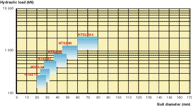
32 Hydraulic force diagrams for standard tensioners These hydraulic force diagrams help define the type(s) of tensioners which best suit your application, depending on the size of the bolt and the traction load to apply. In addition, you must verify the other characteristics with respect to your operational constraints (space, weight, time ). HTA HTS HTS N 3 0


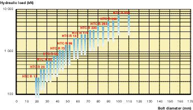

33 HTS2 HTC R HTH R 3 1
34 S u m m a ry Table: Standard Te n s i o n e r This table summarizes the main features of each tensioner, in order to help you select the standard tensioner for your operational requirements. HTA HTS HTS N Tightens several diameters (1) Yes Yes Yes Diameters of the bolts tightened Small and large Small and very small Small Space occupied by the tensioner Normal Small Little Tightening load High High Average Stroke arresting device Optional Optional Optional Automatic return No Optional Optional Cost index (2) 0 (base) 10 Special Feature Adaptable Very small bolt diameters The same tensioner can tighten several diameters Catalogue page (1) by changing the brace (2) indicative, also takes into account the loads applied 3 2
35 C h a r a c t e r i s t i c s HTS 2 HTC R HTH R Yes No Yes Small and average Small and large Large and very large Very little Compact Very little High Very high Very high Optional Yes Yes Optional Yes Yes Fits in very narrow spaces Compact and powerful Takes up very little space and very powerful


36 HTA Tensioner component reference M u l t i - p u r p o s e HTA..T.. The dimensions and the traction load suit this tensioner to many different applications. HTA..C Reference example for a complete tensioner for M8 bolts: HTA..J HTA 90 M8 x 5 Reference example for the M8 x 5 brace for the HTA 90 tensioner: optional HTA 90T M8 x 5 3
37 HTA M u l t i - p u r p o s e Tensioner reference HTA HTA 35 HTA 50 HTA 0 HTA 90 HTA 130 HTA HTA 0 HTA 250 HTA 3 Bolt dimension (M Ø x pitch) Metric system M x 2.5 M 22 x 2.5 M 2 x 3 M 27 x 3 M 27 x 3 M 30 x 3.5 M 33 x 3.5 M 3 x M 3 x M 39 x M 2 x.5 M 5 x.5 M 2 x.5 M 5 x.5 M 8 x 5 M 52 x 5 M 5 x.5 M 8 x 5 M 52 x 5 M 5 x 5.5 M 0 x 5.5 M 0 x 5.5 M x M 8 x M 72 x M 7 x M 72 x M 7 x M 80 x M 80 x M 85 x M 90 x M 95 x M 0 x M 0 x M 1 x M 1 x M 125 x M 125 x M 130 x M 10 x M x Ø in - Threads/in Imperial system 3/ - 7/ / / / - 1 3/8-1 1/2-1 3/ /2-1 3/ /2 1 3/ /2 2 1/ - 1/2 2 1/2-2 3/ / / - 3 1/ - 3 1/2-3 3/ - 3 3/ - - 1/ - 1/2-3/ / - 5 1/2-5 3/ - Max. Pressure (MPa) (psi) Hydraulic area (cm 2 ) (in 2 ) Max. hydraulic load (kn) (lbf) Piston stroke (mm) D (mm) H (mm) H1 (mm) D1 (mm) D2 (mm) A (mm) U (mm) X (mm) Y (mm) Z (mm) Total tensioner weight (kg)


38 HTS Tensioner component reference S m a l l The HTS tensioner is specially HTS..T.. desigined to tighten small bolts (starting with M8). However, it can also tighten large bolts. Its design also tolerates HTS..C possible geometric faults in the assembly parts. Reference example for a complete tensioner for M12 bolts: HTS 9 M12 x 1.75 Reference example for the M8 x 5 body for the HTS 9 C tensioner: HTS 9 C HTS..J optional 3
39 HTS S m a l l Tensioner reference HTS 5 HTS 9 HTS 17 HTS 2 HTS 37 HTS 55 HTS 83 HTS 135 HTS 180 HTS 250 Bolt dimension (M Ø x pitch) Metric system M 8 x 1.25 M x 1.5 M 12 x 1.75 M x 1.5 M 12 x 1.75 M 1 x 2 M 1 x 2 M 1 x2 M 1 x 2 M 18 x 2.5 M x 2.5 M 18 x 2.5 M x 2.5 M 22 x 2.5 M 2 x 3 M x 2.5 M 22 x 2.5 M 2 x 3 M 27 x 3 M 2 x 3 M 27 x 3 M 30 x 3.5 M 33 x 3.5 M 33 x 3.5 M 3 x M 39 x M 2 x.5 M 5 x.5 M 5 x.5 M 8 x 5 M 52 x 5 M 5 x 5.5 M 5 x 5.5 M 0 x 5.5 M x M 8 x M 72 x M 7 x M 80 x M 80 x M 85 x M 90 x M 95 x M 0 x Ø in - Threads/in Imperial system 5/1-18 3/8-1 7/1-1 3/8-1 7/ - 1 1/2-13 9/1-12 5/8-11 9/1-12 5/8-11 3/ - 3/ - 7/ / / / / / /8-1 1/2-1 3/ / /2 2 1/ - 1/2 2 1/ - 1/2 2 1/2-2 3/ / - 3 1/2-3 3/ - Max. Pressure (MPa) (psi) Hydraulic area (cm 2 ) (in 2 ) Max. hydraulic load (kn) (lbf) Piston stroke (mm) D (mm) H (mm) H1 (mm) D1 (mm) D2 (mm) A (mm) U (mm) X (mm) Y (mm) Z (mm) Total tensioner weight (kg)


40 HTS N Thin Tensioner component reference HTS 2..ES This tensioner is designed to fit into narrow spaces. It is also used HTS..C when bolts are spaced close t o g e t h e r. It particularly suits tightening big bolts with low traction load. HTS N..T.. Reference example for a complete tensioner for 1 1/8-7 bolts: HTS N 2 1 1/8-7 Reference example for the 1 1/8-7 brace of the HTS N 2 tensioner: HTS N 2 T 1 1/8-7 HTS 2..J optional 3 8
41 HTS N T h i n Tensioner reference HTS N 17 HTS N 2 HTS N 37 HTS N 55 HTS N 83 HTSN 135 Bolt dimension (M Ø x pitch) Metric system M x 2.5 M 22 x 2.5 M 2 x 3 M 27 x 3 M 2 x 3 M 27 x 3 M 30 x 3.5 M 33 x 3.5 M 27 x 3 M 30 x 3.5 M 33 x 3.5 M 3 x M 39 x M 3 x M 39 x M 2 x.5 M 5 x.5 M 8 x 5 M 5 x.5 M 8 x 5 M 52 x 5 M 5 x 5.5 M 0 x 5.5 M 0 x 5.5 M x M 8 x M 72 x M 7 x M 80 x Ø in - Threads/in Imperial system 3/ - 7/ / / / / / /8-1 1/2-1 3/8-1 1/2-1 3/ / /2 2 1/ - 1/ 2 2 1/ - 1/ 2 2 1/2-2 3/ Max. Pressure (MPa) (psi) Hydraulic area (cm 2 ) (in 2 ) Max. hydraulic load (kn) (lbf) Piston stroke (mm) D (mm) H (mm) H1 (mm) D1 (mm) D2 (mm) A (mm) U (mm) X (mm) Y (mm) Z (mm) Total tensioner weight (kg)


42 HTS 2 Thin and powerful Tensioner component reference HTS 2..ES Like the HTS N Tensioner, HTS 2 takes up very little space. HTS 2..C Due to its two-story design, there is greater tightening load for a given diameter as compared with HTS or HTS N. HTS 2..T Reference example for a complete tensioner for M3 bolts: HTS 2 37 M3 x Reference example for the HTS 2 37 tensioner upper screw: HTS 2..J HTS 2 37 ES optional 0
43 HTS 2 Thin and powerful Tensioner reference HTS2 17 HTS2 2 HTS2 37 HTS2 55 HTS2 83 HTS2 135 Bolt dimension (M Ø x pitch) Metric system M x 2.5 M 22 x 2.5 M 2 x 3 M 27 x 3 M 2 x 3 M 27 x 3 M 30 x 3.5 M 33 x 3.5 M 27 x 3 M 30 x 3.5 M 33 x 3.5 M 3 x M 39 x M 3 x M 39 x M 2 x.5 M 5 x.5 M 8 x 5 M 5 x.5 M 8 x 5 M 52 x 5 M 5 x 5.5 M 0 x 5.5 M 0 x 5.5 M x M 8 x M 72 x M 7 x M 80 x Ø in - Threads/in Imperial system 3/ - 7/ / / / / / /8-1 1/2-1 3/8-1 1/2-1 3/ / /2 2 1/ - 1/ 2 2 1/ - 1/ 2 2 1/2-2 3/ Max. Pressure (MPa) (psi) Hydraulic area (cm 2 ) (in 2 ) Max. hydraulic load (kn) (lbf) Piston stroke (mm) D (mm) H (mm) H1 (mm) D1 (mm) D2 (mm) A (mm) U (mm) X (mm) Y (mm) Z (mm) Total tensioner weight (kg)


44 HTC R Tensioner component reference Compact and powerful HTC R, the most powerful tensioner in the Hydrocam standard range, can apply very high traction loads. The brace and the body are HTC R..C.. monolithic. The HTC R tensioner, with its automatic piston return and few parts, is very easy to use and well-suited to simultaneous tightening. Each unit is dedicated to a single bolt diameter Reference example for a complete tensioner for 2 1/2 - bolt: HTC R /2 - Reference example for the HTC R 137 tensioner body for a 2 1/2 - bolt: HTC R 137 C 2 1/2 - HTCR..J optional 2
45 HTC R Compact and powerful Tensioner reference HTC R 17 HTC R 2 HTC R 0 HTC R 5 HTC R 73 HTC R 98 HTC R 137 HTC R 17 HTC R 2 HTC R 28 HTC R 32 HTC R 500 Bolt dimension (M Ø x pitch) Ø in - Threads/in Metric system Imperial system M x 2.5 M 22 x 2.5 3/ - 7/8-9 M 2 x 3 M 27 x /8-7 M 30 x 3.5 M 33 x / / - 7 M 3 x M 39 x 1 3/8-1 1/2 - M 2 x.5 M 5 x.5 1 3/8-1 1/2 - M 8 x 5 M 52 x 5 1 3/ /2 M 5 x 5.5 M 0 x / -1/2 2 1/2 - M x M 8 x 2 1/2-2 3/ - M 72 x M 7 x 2 3/ M 80 x M 85 x 3 1/ - 3 1/2 - M 90 x M 95 x 3 1/2-3 3/ - M 0 x M 1 x - 1/ - Max. Pressure (MPa) (psi) Hydraulic area (cm 2 ) (in 2 ) Max. hydraulic load (kn) (lbf) Piston stroke (mm) D (mm) H (mm) H1 (mm) D1 (mm) D2 (mm) , A (mm) U (mm) X (mm) Y (mm) Z (mm) Total tensioner weight (kg)


46 HTH R Thin and super-powerful Tensioner component reference HTH R..ES This full-option tensioner provides maximum power for a minimum of space. Built on two or three stories (depending on the diameters to be tightened), this is the thinnest tensioner in the Hydrocam standard product range. In most cases, it requires the use of cylindrical nuts. The HTH R also has an automatic piston return mechanism and is very well-suited to simultaneous t i g h t e n i n g. Reference example for a complete tensioner for M72 bolts: HTH R 8 M72 x Reference example for the HTH R 8 tensioner skirt: HTH R 8 J HTH R..C HTH R..T.. HTH R..J Accessory
47 HTH R Thin and super- p o w e r f u l Tensioner reference HTH R 17 HTH R 3 HTH R 5 HTHR 2 HTH R 82 HTH R 8 HTH R 135 HTH R 180 HTH R 223 HTH R 270 HTH R 335 HTH R 27 HTH R 57 Bolt dimension (M Ø x pitch) Metric system M x 2.5 M 22 x 2.5 M 2 x 3 M 27 x 3 M 30 x 3.5 M 30 x 3.5 M 33 x 3.5 M 3 x M 39 x M 2 x.5 M 2 x.5 M 5 x.5 M 8 x 5 M 8 x 5 M 52 x 5 M 5 x 5.5 M 5 x 5.5 M 0 x 5.5 M x M x M 8 x M 72 x M 72 x M 7 x M 80 x M 80 x M 85 x M 90 x M 90 x M 95 x M 0 x M 0 x M 1 x M 1 x M 1 x M 125 x M 125 x M 130 x M 10 x M 10 x M x M x Ø in - Threads/in Imperial system 3/ - 7/ / / /8-1 1/2-1 1/2-1 3/ / /2 2 1 / -1 / 2 2 1/2-2 1/2-2 3/ - 2 3/ / - 3 1/2-3 1/2-3 3/ - 3 3/ - - 1/ - 1/2-3/ / - 5 1/2-5 1/2-5 3/ - Max. Pressure (MPa) (psi) Hydraulic area (cm 2 ) (in 2 ) Max. hydraulic load ( k N ) (lbf) Piston stroke (mm) 8 D (mm) H (mm) H1 (mm) D1 (mm) D2 (mm) U (mm) X mini (mm) Y mini (mm) Z mini (mm) Total tensioner weight (kg)


48 Customized standard tensioners Do you have a specific assembly? SKF Equipements adapts the tensioner to your application. A Hydrocam standard tensioner has been selected for your application but there may be one feature of your bolted assembly which prevents the tensioner from being u s e d. SKF Equipements can easily adapt the following components of the tensioner to fit your size and accessibility c o n s t r a i n t s : - the brace - the skirt - the socket - the reaction nut The examples of customized parts shown below portray only a small portion of what can be done the possibilities are endless. Customized braces... Standard body Customized skirts... Customized sockets... If your application presents special characteristics which preclude using a standard body, please turn to the page Special Tensioners, on pages 8 and 9.
49 Simultaneous tightening equipment for the cylinder head on large diesel engines


50 Special Tensioners You have a specific application which requires a design study. SKF Equipements designs, computes, optimizes and manufactures the hydraulic tensioner to meet your needs. SKF Equipements offers tailor-made design of the various tensioner components, in compliance with your application requirements. The operating principle remains the same, however new functions can be added. A b r i e f overview of SKF expertise follows: - The general shape, size and number of components can vary as needed, to fit the accessibility, size restrictions and handling constraints. - The choice of the materials and heat treatments is adapted to meet the mechanical and weight specifications of an application. SKF tensioners can also be manufactured in lighter materials such as titanium. - The tensioner environment can require the use of specific hydraulic fluids. Hydrocam tensioners can be designed to work with all types of hydraulic connectors. - Turning down operations can be motorized and fully a u t o m a t e d. - In cases requiring high accuracy, SKF can supply sensor washers or devices to measure bolt elongation. - For improved tightening uniformity over several bolts, we recommend either total (preferably) or partial simultaneous tightening. Let us know your needs we will meet them! Stainless steel tensioner works with water compact no pollution of the assembly environmentally friendly Titanium tensioner works with water ultra-light easy handling designed to be handled by a diver in an underwater environment Monolithic 8-tensioner ring simultaneous, homogenous tightening quick, simple use Compact tensioner tightens hard-to-reach bolts controls turning-down operations 8


51 Micro tensioner compact tightens very small bolts (M5) highly accurate (a few microns of screw elongation) Tensioner for automatic multiple stud tensioner machines, nuclear reactor vessel opening and closing operations remote-controlled highly efficient application of high tightening pre-loads Excellent efficiency Tensioner for 500 mm diameter bolts Tensioners for very large diameter bolts Tighten very large diameter bolts Automatic piston return Retaining sleeve or clamping jaws 9


52 Special machines and control systems Your application requires remote control tightening which is simultaneous, controlled, accurate and totally safe. SKF Equipements researches your application and adds hydraulic tensioners to instrumentation and control systems. In adding Hydrocam hydraulic tensioners to an instrument, regulation and control system, you automate and protect your tightening. You can also ensure homogenous tightening by using a simultaneous tightening procedure, and improve accuracy by using measurement and control devices. The handling phases can be automated and included in the machine operating process, resulting in reliable, accurate and rapid tightening operations. The following lists a brief sampling of some of the automated functions commonly found in special tightening machines: pressure increase for controlled tensioners turning down operations for the nuts to be tightened automatic piston return stud screwing and unscrewing piston stroke control measurement of bolt elongation continuous measurement of the tightening load Remote control of a tightening machine working in a risk area Central feed individual tensioner simultaneous tightening 5 0
 or")
.")


53 C A D of the MST (Multiple Stud Te n s i o n e r ) or MSDG (Stud Tightening and Untightening Machine). On-site assembly of the MST MST remote control panel Automatic MST machine with 5 studs, preparing the closure of a nuclear reactor vessel. 5 1


54 Applications The Hydrocam range provides you with the tensioner which meets your economic criteria 1. Civil Engineering Safety Performance The tightening operations for the clamp bolts on the primary load-bearing cables of suspended bridges are performed with Hydrocam HTA tensioners, known for their flexibility and ease-of-use. For these and other crucial tasks, where access is diff i c u l t and conditions are severe, the tightening tool must guarantee good performance, resistance, efficiency and easy handling. 2. Public works machinery Critical tightening level and homogeneity The safety of the bolted assemblies - on crane slewing rings for example largely depends on the high tightening level and on the uniformity of the applied tightening load. Hydrocam tensioners such as HTH R, HTC R, HTS 2 or N require little space and apply extremely high, uniform tightening loads in each bolt. The low drag friction c o e fficients of the seals which equip the hydraulic body ensure high quality assembly and excellent homogeneity. 3.Wind turbines Rapid service The use of double-acting HTC R Hydrocam tensions with automatic piston return means fast performance of all the tightening operations on wind turbines, without interrupting production. This guarantees the performance and reliability of these heavy-wear machines, ensuring ongoing electricity production. 5 2


55 . Nuclear industry Safety Lower dosimetry Bolted assemblies in the nuclear industry are subject to extremely strict quality rules to ensure safety. Hydrodcam HTA and HTS standard tensioners, operating with oil or water, alone or simultaneously, meet the demanding nuclear industry requirements for tightening operations. In addition to standard tensioners, specialized Hydrocam tensioners using automatic feed and control equipment, can be used for remote, rapid tightening of specific assemblies. This reduces contamination and dosimetry risks for the operators. 5. Aeronautics Precision - Weight reduction In the aeronautics industry, customized HTS Hydrocam tensioners, used alone or simultaneously, tighten very small bolts with high accuracy, reducing the time required for assembly operations. Hydrocam tensioners take full advantage of the mechanical properties of the main assembly materials used in aeronautics, reducing weight. If necessary, water-based tensioners can be supplied.. Diesel Engines Reduced flywheel mass Bolted assemblies in engines have to withstand heavy mechanical stresses, particularly dynamic. With the use of customized HTA or HTC R Hydrocam tensioners, you can take full advantage of the mechanical characteristics of the materials in the primary assemblies, leading to reduced volumes and masses, in particular flywheel masses. Engine performance and operating costs are clearly improved. 5 3


56 Company resources and organization at the client s service The ITE Department at SKF Equipement is totally client-oriented. It disposes of the resources and the organization it needs to meet its customers n e e d s... Located in spacious, well-designed premises in France, Paris area C u s t o m e r-focused approach combining quality, p e rformance and friendliness. A team of engineers which combines understanding, expertise, experience and a forward-thinking attitude to analyze clients needs and provide the best s o l u t i o n s 5 The Design Department works on the cutting edge (CAD, analytical software and finite element structural analysis)

 Well-equipped production and assembly workshops.")

57 Control and verification instrumentation to measure hardness, dimensions, surf a c e condition, geometrical defects Mechanical test beds to measure loads, stresses and strains, to determine equipment performance and lifetime Hydraulic test beds (using oil and water), for low-pressure tests (0-300b), and high pressure tests ( b) Well-equipped production and assembly workshops.... and in addition SKF s quality organization has been acknowledged by ISO 9001 certification ; A powerful network of partners, subcontractors and suppliers, carefully selected and regularly audited ; And the entire SKF network, capable of meeting customer demand anywhere in the world. 5 5


58 SKF Equipements Services Work alone no longer! SKF Equipements offers its partnership for all your tightening applications. Assistance in designing bolted assemblies You have to design new bolted assemblies or revise the design of existing assemblies. S K F s vast experience on a wide range of applications has led to the creation of a complete set of theoretical and practical tooling and hardware which can solve nearly any problem encountered in the field of bolted assembly tightening. SKF can therefore offer its assistance from the very start of the design stage. This saves you precious time and frees you to concentrate on the design aspects which are at the core of your business. In addition, you reap all the advantages which result from optimized bolted assembly design: saved space, less weight, increased safety, easier assembly and m a i n t e n a n c e. Checks and tests You most certainly conduct many checks and tests on your application, however the skilled operators and the proper tooling can be very demanding. This can lead to very complex situations which cannot always be solved in-house. SKF offers the full range of tooling it has developed over the years, and can provide you with or design the specific, effective and practical solution for your problem. SKF teams are expert users of this equipment, and can m o d i f y, adapt or redesign existing tooling to meet your needs. In a word rapid, effective service in the testing field. Assistance in selecting the best tightening method You are dealing with tightening or loosening problems on an existing bolted assembly. SKF has faced such problems daily, and has a wide range of solutions. Turn to SKF for assistance in selecting the most eff e c t i v e tightening method for your needs, given your space constraints, loads, time, environment, cost and other issues. Expertise and experiments You would sometimes like to have an expert opinion, or conduct an experiment on bolted assemblies. Thanks to the wide variety of problems solved with their clients, SKF has gained in-depth expertise in the field. SKF has long been conducting on-going experiments, and has developed specifications, procedures, protocols and instructions SKF can help you define, calculate, measure and analyze the static and dynamic loads applied on the bolts in your assemblies, both on stand-by and in service. SKF offers its services in every area where error or the wrong direction can have serious consequences on costs and schedules. Optimizing the number of rounds required for the partial simultaneous tightening of a 9-bolt flange, using 8 tensioners. On-site intervention, tightening the man hole hatch on the primary cooling system of a steam generator. 5


59 Training Although the field of bolted assemblies is highly complex and vast, it is relatively rarely included in the curricula followed by engineers and technicians. Based on its long-standing experience, SKF has developed training programs which can be very useful for your teams dealing with bolted assemblies. SKF can also off e r tailor-made programs to meet the specific requirements you have identified. Maintenance and repair / in the workshop and on-site You may not have a repair shop able to maintain and repair the tightening equipment. SKF can do this work for you, preferably in their own workshops if the material can be sent back, or on-site, if working conditions are conducive to performing maintenance, overhaul and repair on the site. Industrial partnerships You are looking for an industrial partner capable of supplying you with regular or periodic service in one or several of the previously described areas. SKF offers you a partnership arrangement in which SKF commits to supplying the required services in a time frame and way which are to be defined. SKF offers total flexibility to come up with the formula which best meets the client s needs. Training on hydraulic tensioner tightening techniques Technical support / On-site assistance There is no lack of jobs to be done in your workshops and on your sites. However, you may not always have skilled employees on hand to do the job where and when it needs to be done. SKF can send skilled technicians to your workshops and site, to provide you with the help you need. On-site, in addition to working with the tightening tools, SKF can perform many other tasks, such as: repairing and reconditioning the parts to be tightened (cleaning, grinding, adjustment, control ) repair and preparation of sealing surfaces replacement of assembly parts cutting bolts to be replaced checking the tightening loads using the most appropriate means, and others. SKF also provides rental equipment for temporary, short-term use. Installation and commissioning You have purchased new bolt tightening equipment. Perhaps your staff is not yet familiar with the equipment, or you prefer or are not able to assign a task force to implementing it. SKF offers installation and commissioning services, and can also operate the equipment for you each time you need to use it. Display of assembly strain during bolt tightening using Hydrocam tensioners. Kit demonstrating the use of Hydrocam tensioners with the BoltSafe sensor washer. 5 7


60 Tensioner Accessories High pressure hoses High pressure hoses are supplied with high pressure self-sealing quick-coupling connectors, in unit lengths up to 300 m. Two types of hose depending on the pressure used: HFC: operating pressure: MPa: Bursting pressure: 50 MPa TFC: operating pressure: 300 MPa: Bursting pressure: 550 MPa Designation example: HFC 1: 1-m long hose, operating pressure MPa MFC 2: 2-m long hose, operating pressure 80 MPa Ref: MFC, HFC or TFC (specify length) High pressure quick-coupling connectors The self-sealing quick-coupling connectors on the Hydrocam tightening and pressure supply equipment are heavy-duty and easy to use. There are three types of quick-coupling connectors depending on the pressure used: HBC ; HBC 15; HBC 30. Designation example: HBC 15 N/M: quick-coupling male connector, operating pressure: MPa HBC 30 N/F: quick-coupling female connector, operating pressure: 300 MPa ref: HBC.. (specify pressure) Distribution blocks The distribution blocks can simultaneously connect several hydraulic tensioners. They are equipped with high pressure self-sealing quick-coupling connectors. You select the number of outlets. Designation example: HDB 1-2: distribution block one inlet two outlets HDB 1-3: distribution block one inlet three outlets Oil can ref: HDB1-.. (specify number of outlets) Hydraulic oil is supplied in 5-liter cans. All Hydrocam tools are delivered fully oiled and ready to use. 5 8 ref: HCO 5L
, the hydraulic flowrate at 0 MPa is 0.2 l/min. This unit has a class 1 manometer, a 5-liter tank and 2 hydraulic outlets with quick-coupling, self-sealing connectors.")
, calibrated")

61 Air-driven hydraulic generating set This air-driven hydraulic generating set, equipped with an air/oil pressure intensifier, supplies adjustable pressure of 300 MPa, calibrated by the air inlet. For air supply of 0. MPa ( bar), the hydraulic flowrate at 0 MPa is 0.2 l/min. This unit has a class 1 manometer, a 5-liter tank and 2 hydraulic outlets with quick-coupling, self-sealing connectors. Dimensions: W 30 x D 3 x H 50 mm Weight: 3 kg. Air-driven hydraulic generating set GHP 0 This air-driven hydraulic generating set, equipped with an air/oil pressure intensifier, supplies adjustable pressure of MPa (0 MPa on request), calibrated by an air inlet. For air supply of 0. MPa ( bar), the hydraulic flowrate at 0 MPa is 0.2 l/min. This hydraulic set has a class 1 manometer, a 5-liter tank, and 2 hydraulic outlets with quick-coupling self-sealing connectors. Dimensions: W 30 x D 3 x H 0 mm Weight: 2 kg. ref: GHP 300 ref: GHP 0 Electro hydraulic generating set GHE 0 This electro hydraulic generating set, equipped with a 0.55 kw electric motor, 15/20/1 voltage and a pressure intensifier, supplies pressure of MPa (0 MPa on request). The hydraulic flowrate at 0 MPa is 0.8 l/min. This hydraulic set has a class 1 manometer, a 5-liter tank, and 2 hydraulic outlets. Dimensions: W 250 x D 170 x H 35 mm Weight: 27 kg. ref: GHE 0 Pressure intensifier This device enables setting a constant pressure ratio between the inlet and the outlet of the pressure intensifier. The pressure ratio must be defined when ordering. Two types of pressure intensifiers are available: ILP: pressure ratio from 1.1 to 5 IHP: pressure ratio from 5 to S e l f - l o cking caps for hex agonal nu t s Made of polyethylene Black High-performance: the circular hold ring clips on under the nut. Total protection from pollution, impact, corrosion, chemicals, gouges. ref: CAP.. (specify bolt dimension) ref: ILP ou IHP.. (specify pressure ratio) 5 9


.")
. At low pressure, the volume for each piston stroke is 17.5 cm 3. At high pressure, it is 1.25 cm 3. Weight:1 kg.")
. Volume per piston stroke is 1 cm 3. Weight: 3.5 kg.")
62 Sealing kit for Hydrocam bolt tightener hydraulic bodies The composite sealing kit for the Hydrocam bolt tightener hydraulic bodies good high pressure performance, great wear resistance and a low drag friction coefficient, providing efficiency on the order of 98%. These high performance characteristics contribute to high quality bolted assemblies. Sealing kits for standard tensioners are in stock. The reference refers to the hydraulic body. Designation examples: HAK : sealing kit for HTA C standard hydraulic body HSK 50: sealing kit for HTS 50 C standard hydraulic body. ref: HAK, HSK, HCK or HHK (the hydraulic section of the tensioner) Tommy bar Tommy bars are used to screw the braces and turn down the nut by rotating the hydraulic tensioner socket. Tommy bar diameters depend on the tensioner model they are used with. Ref: BR -8. BR -12. BR BR 1-1. ref: BR.. (specify dimensions, see table page 1). Double stage manual pump The double stage manual pump is equipped with a manometer and a 3-m high pressure hose with a self-sealing quick-coupling connector. It has a 2300 cm 3 tank and applies pressure up to MPa (0 bar). At low pressure, the volume for each piston stroke is 17.5 cm 3. At high pressure, it is 1.25 cm 3. Weight:1 kg. Comes in a steel carrying case. ref: PH 0 Single stage small manual pump This small single stage manual pump is equipped with a manometer and a 1.5 m high pressure hose with a self-sealing quick-coupling connection. It has a 250 cm 3 tank and applies pressure of 0 MPa (00 bar). Volume per piston stroke is 1 cm 3. Weight: 3.5 kg. Comes in a steel carrying case. ref: PH 00 S Single stage manual pump This single stage manual pump is equipped with a manometer and a 1.5 m high pressure hose with a self-sealing quick-coupling connection. It has a 700 cm 3 tank and applies pressure of 0 MPa (00 bar). Volume per piston stroke is 1 cm 3. Weight: kg. Comes in a steel carrying case. ref: PH 01 0


63 Sockets Réf: ACC.. (specify bolt diameter) The sockets enable easy turning down (or up) of the hexagonal nuts during hydraulic tensioner tightening (or untightening). The standard socket is a hexagonal bore which fits the application nuts. Designation example: ACC M 39: socket for M39 bolt diameter ACC 1 1/ : socket for 1 1/ bolt The range of standard sockets covers bolt dimensions from M8 to M (5/1 to ). See table below. Stud outside diameter Ø D width across flats A width across points B Height H tommy bar Ø C M 8 M M 12 M 1 M 1 M 18 M M 22 M 2 M 27 M 30 M 33 M 3 M 39 M 2 M 5 M 8 M 52 M 5 M 0 M M 8 M 72 M 7 M 80 M 85 M 90 M 95 M 0 M 1 M 1 M 125 M 130 M 10 M In some applications, the nuts may be cylindrical or have special shapes. For cylindrical nuts, sockets are not required. For special shape nuts, SKF manufactures custom-made sockets. 1

64 The sensor washer What is the tightening pre-load in my bolt? Your bolted assembly is a critical part of your application, and reliability is crucial. The BoltSafe sensor washer, designed by the ScanSafe company, provides you with the information you need on the reliable operation of your application. BoltSafe washers are integrated into your application, where they are as easy to use as any normal washer. Using a handheld reader or a PC connected to your application s BoltSafe networks, you can accurately monitor the tightening pre-load of each BoltSafe washer equipped bolt in your application. This way, you can easily check if the prescribed tightening load remains throughout operations. You ensure operational safety and the reliability at low cost. What is the accuracy? BoltSafe washers are an excellent means of monitoring, for they are capable of detecting any load variation in the bolt. The accuracy of the measurement of the absolute load in the bolt depends on several factors. First of all, Hydrocam tensioners must be used to guarantee measurement accurac y, particularly in the case where the washer is placed directly under the nut. Indeed, after turning down the nut and releasing the pressure of the tensioner, solely the axial tightening pre-load is applied on the washer, whereas, with torque tightening, torsion stresses are induced in the BoltSafe washer. In addition, torque tightening misaligns the washer with respect to the bolt, which significantly impairs measurement accuracy. Accurate load measurement also depends on assembly q u a l i t y, such as the perpendicularity of the bearing faces with respect to bolt axis, surface flatness, absence of holes, gouges and roughness on the assembled parts in contact with the BoltSafe washer faces. 2
 to conduct a magnetic field is an almost linear function of the stress")


. L a s t l y, efficient monitoring of load in operation will depend on the positioning of the BoltSafe washers, which must be carefully chosen.")
65 How does it work? The BoltSafe washer operating concept is based on the fact that material s ability (depending on its structural quality) to conduct a magnetic field is an almost linear function of the stress inside the material. Each washer contains an electronic chip which processes the measurement and transforms it into a digital signal. T h e chip provides unique identification of the BoltSafe washer and integrates it in the BoltSafe washer network. Optimum tightening with BoltSafe washers and Hydrocam tensioners. In the case of tightening of a flange or a bolted assembly, the use of Hydrocam tensioners on each bolt is suff i c i e n t l y e fficient to avoid the need for a BoltSafe sensor washer on each bolt. A few BoltSafe washers are sufficient. T h e Hydrocam tensioner ensures the homogeneity and the repeatability of the tightening, and the washer provides knowledge of the bolts pre-load with increased accuracy. If the number of tensioners used is lower than the number of bolts in the assembly, the number of BoltSafe washers on the bolts should be increased. This way, the BoltSafe washer network will more easily detect variations in the pre-load on the bolts when the specific procedure is applied to a partial simultaneous tightening (see simultaneous tightening in the Bolt-tightening Handbook). L a s t l y, efficient monitoring of load in operation will depend on the positioning of the BoltSafe washers, which must be carefully chosen. Hydrocam tensioner tightening with the BoltSafe CMS tightening measurement washer. Where is the BoltSafe washer used? BoltSafe washers are already used in every kind of bolted assembly which is subjected to load variations due to vibrations, changes in temperature, pressure, external loads or any other mechanical influence. In these and other situations, BoltSafe washers can monitor the tightening level. Add your application to the growing list using BoltSafe washers for accurate measurement. 3

 connected to the SM-0 by a cable the BoltSafe PMS washer (Periodic Monitoring System) which is read through")

66 Monitoring The tightening level of your application can be monitored in several different ways depending on the number of BoltSafe washers and on the security and monitoring program in place for your application. Monitoring individual BoltSafe washers If a number of BoltSafe washers are individually installed throughout your application, each washer can be read with a simple SM-0 handheld reader, which can read two types of BoltSafe washers: the Bolt Safe CMS washer (Continuous Monitoring System) connected to the SM-0 by a cable the BoltSafe PMS washer (Periodic Monitoring System) which is read through a probe in contact with an electronic interface in the washer. There is also a SM-0 reader similar to the SM-0 r e a d e r, yet with an additional storage function to store the information from 255 BoltSafe washers. This information can be downloaded to a PC using BS-00 software. With this monitoring system, the operator must come close to each BoltSafe washer to read the measurement. Equipment description Handheld reader with no memory Handled reader with memory BoltSafe network adapter BoltSafe analysis and display software R e fe r e n c e S M - 0 S M - 0 C M - 00 B S - 00 Monitoring a network of BoltSafe washers The BoltSafe washers in your application can also be connected to a central station, the CM-00, which displays the tightening load level on each washer. In this case, a pocket computer (Palm Top) or a portable computer (laptop) is used to interrogate, identify and store the measurement from each one of the BoltSafe washers in the network. This reader can then be directly connected to a PC to download the data using BS-00 software. With this monitoring system, the operator reads the BoltSafe washer information from a single spot, close to the application. Power and signal interface unit Networked boxes up to 8 washers PDA Lap Top PC Internet telephone The BS-00 software processes the data from the BoltSafe washers.

67 Remote monitoring of the BoltSafe network The BoltSafe washer network in a strategic application can be an integral part of a company s security and monitoring system. The objective is to detect and warn of any abnormal situation reflected by variations in the tightening pre-load in the bolts in the application. In this monitoring arrangement, the BoltSafe washers are connected to interconnected CM-00 stations. A s i n g l e network station is then connected to a PC (RS-232 connection) and to the BS-00 program, where warning levels can be programmed to warn the overall surveillance system. Or, the PC can be remotely polled and can provide information from afar The BS-00 program The BS-00 program was specially designed to provide the user with user-friendly interface enabling him to instantaneously review residual pre-tension directly on the screen. The program is easy to use and to understand. It uses the structures, icons and drag-and-drop functionality from the standard Windows environment. Residual pre-tension data can be analyzed in three d i fferent ways (list, bar chart and histogram) and can be saved to files or printed. BS-00 software can also be concurrently used to upload data recorded in the SM-0 reader or from a hand-held r e a d e r. In the case of remote surveillance, software functions can be added to provide access to the monitored BoltSafe network by all control systems. 5
 Inside diameter A (mm) Outside diameter B (mm) T h i c k n e s s C (mm) We i g h t ( g r ) M a x i m u m tightening load (kn) Class.")
68 The Standard range CMS washer The BoltSafe CMS (Continuous Monitoring System) washer is connected to a SM-0 or CM-00 station via cable. Metric system B o l t d e s c r i p t i o n B o l t diameter (mm) Inside diameter A (mm) Outside diameter B (mm) T h i c k n e s s C (mm) We i g h t ( g r ) M a x i m u m tightening load (kn) Class.9 M M M M M M M M M M M M M M M Imperial system B o l t d e s c r i p t i o n B o l t diameter (mm) Inside diameter A (mm) Outside diameter B (mm) T h i c k n e s s C (mm) We i g h t ( g r ) M a x i m u m tightening load (kn) Class.9 7/8'' '' /8'' /'' /8'' /2'' /8'' /'' /8'' '' /'' /2''
69 The Standard range PMS washer The BoltSafe PMS (Periodic Monitoring System) washer. Measurement is read through a probe in contact with an electronic interface in the washer. Metric system B o l t d e s c r i p t i o n B o l t diameter (mm) Inside diameter A (mm) Outside diameter B (mm) T h i c k n e s s C (mm) We i g h t ( g r ) M a x i m u m tightening load (kn) Class.9 M , M , M3 3 3, M , M2 2 2, M5 5 5, M8 8 8, M , M5 5 5, M0 0 0, M, Imperial system B o l t d e s c r i p t i o n B o l t diameter (mm) Inside diameter A (mm) Outside diameter B (mm) T h i c k n e s s C (mm) We i g h t ( g r ) M a x i m u m tightening load (kn) Class.9 1 1/'' 31,8 32, /8'' 3,9 35, /2'' 38,1 38, /8'' 1,3 1, /'',5 5, /8'' 7, 8, '' 50,8 51, /'' 57,2 57,8 8, /2'' 3,5,3 11,
70 Glossary of terms Bolt Class Tensile stress Hydraulic load Residual load E x t e rnal load E l o n g a t i o n S t u d Yield point F a i l u re limit Tightened length P re - s t ressing Bolt stiffness Automatic re t u rn Equivalent bar area Hydraulic are a Category of bolts defined by the mechanical characteristics of failure limit and yield point. Example: Class 12-9 bolt The first figure indicates one hundredth of the failure limit in MPa The second figure indicates the coefficient in ths that would have to be applied to this failure limit in order to find the yield point. Failure limit: MPa Yield point: 80 MPa The relation between the tensile strength exerted on the bolt and its unit area. Force transmitted during tightening operation, by the hydraulic tensioner to the bolt, produced by the hydraulic pressure from the hydraulic area of the tensioner. Force or pre-tension applied on the bolt when the nut has been turned down and the hydraulic pressure has been released. Force applied on the bolted assembly from operation of the application. The stretching of the bolt by tensile stress. A bolt which is threaded on both ends over a certain length. Most often, the central part remains smooth and is generally smaller than the threaded sections. The maximum stress point possible in a bolt in order to undergo no elongation when the tensile stress stops. Beyond this stress limit, the bolt sustains permanent strain. Maximum possible stress causing the failure of the bolt. Distance between the bearing face under the nut and the bearing face under the bolt head or under the other nut head if it is a stud. Stress applied to the bolt when it is tightened, and the result of the relation between the residual load and the equivalent bolt area. Prestress does not take into account the stress from the external load. The theoretically constant ratio between the tensile strength applied on a bolt and the elongation due to this strength. Bolt stiffness depends on the area, the modulus of elasticity and the tightened length. A mechanical device on certain tensioners which returns the piston to its original position when tensioner pressure stops. Cylinder section modeling the threaded part of a bolt, subjected to uniform tension. The calculation of cylinder diameter is based on thread diameter and pitch. Piston area subjected to hydraulic pressure. 8


71 Conclusion This catalogue illustrates SKF Equipements expertise in the industrial tightening field. This catalogue is aimed at helping bolted assembly designers from the very start of the design stage for bolt-tightening applications. The information, the recommendations and the description of the total product range, with its diverse and varied product characteristics, provide the reader with everything he needs to define the equipment which best meets the needs of his application. The crucial message is that tightening is one of the most critical steps in a bolted assembly, and must be thoroughly studied. Every bolted assembly must be tightened just right. There is no such thing as too little or too much tightening. And SKF Equipements can help you define and implement what is just right for you. SKF Equipements can: help you optimize your assemblies help you choose the tensioner(s) adapted to your application design custom tensioners for your needs manufacture special tightening machines. Industrial tightening is our profession. We can help you concentrate on yours. 9
72 Fax / / date From: Company A d d r e s s N a m e Tel N Fax N I would like price information on the following models: Send to SKF Equipements Département Techniques de Serrage Industriel 30-32, avenue des Tr o i s - P e u p l e s F Montigny-le-Bretonneux Fa x : Tel.: Price request Note: for descriptions and references, see the following sections: - standard tensioners pages 3 to 5 - accessories pages 58 à 1 N 5 - RESERVED FOR SKF SKF Equipements offer N Equipment description reference quantity unit price delivery* *d e l i v e ry date upon ordering Comments: For all specific requests, please call us at

73 Fax / / date From: Company A d d r e s s N a m e Tel N Fax N I would like information on Hydrocam Tensioners: Send to SKF Equipements Département Techniques de Serrage Industriel 30-32, avenue des Tr o i s - P e u p l e s F Montigny-le-Bretonneux Fa x : Tel.: Application: existing being validated Information on the Hydrocam Tensioner(s) E q u i p m e n t : Parts to be tightened: Bolt characteristics (specify numbers) Thread diameter (d): Pitch: Bolt diameter (D): Extending length (l): Nut(s): - width across flats (f): - height (h): Washer(s): - φ outside (A): - Thickness (e): Bolt material: Yield point: Class: Bolt distribution (supply diagram if possible) Distribution diameter: Number of screws: Distance between 2 bolts: Optimizing the bolted assembly (dimensions and number of bolts) yes no External load: s t a t i c d y n a m i c Application point: (diagram if possible) Current tightening method (specify units) Torque (wrench) - torque applied: - elongation : Heating rod - temperature: - screwing angle: Other methods Hydraulic tensioner tightening Residual pre-load (per bolt) Hydraulic load (per bolt) Simultaneous tension: y e s n o How much: E x i s t i n g : Feed to provide for: manual pump air-driven generating set Electro hydraulic generating set Space available for the tensioner Height (X): Diameter (Y): Local obstruction (Z1): ( Z 2 ): ( Z 3 ): Drawings enclosed:
Linear Motion & Precision Technologies. H Y D ROCAM Bolt Te n s i o n e rs I n d u s t rial Tightening Systems
 Linear Motion & Precision Technologies H Y D ROCAM Bolt Te n s i o n e rs I n d u s t rial Tightening Systems Introduction SKF has worked in the field of bolt-tightening by pre-load tension since the 1940
Axial-radial cylindrical roller bearings
 Axial-radial cylindrical roller bearings Designs and variants.............. 320 Bearing data..................... 321 (Boundary dimensions, tolerances) Product table 5.1 Axial-radial cylindrical roller
INDEX EASY RAIL: THE SOLUTION IS EASY...D4 EXAMPLES OF LOAD CAPACITIES...D5 ORDER CODES...D6 MOUNTING EXAMPLES...D7 TECHNICAL DATA...
 INDEX EASY RAIL: THE SOLUTION IS EASY...D4 EXAMPLES OF LOAD CAPACITIES...D5 ORDER CODES...D6 MOUNTING EXAMPLES...D7 TECHNICAL DATA...D8 STANDARD CONFIGURATIONS...D10 VERIFICATION UNDER STATIC LOAD...D12
SKF hub units. Equipped with tapered roller bearings
 SKF hub units Equipped with tapered roller bearings A passion for innovation Solutions for the demands of today and tomorrow SKF has always been known as a leader in the development of innovative bearing
DESIGN OF MACHINE MEMBERS - I
 R10 Set No: 1 III B.Tech. I Semester Regular and Supplementary Examinations, December - 2013 DESIGN OF MACHINE MEMBERS - I (Mechanical Engineering) Time: 3 Hours Max Marks: 75 Answer any FIVE Questions
Shaft-Hub-Connections
 Stand: 14.01.2010 Shaft-Hub-Connections Shrink Discs Cone Clamping Elements Star Discs 36 Edition 2012/2013 RINGSPANN Eingetragenes Warenzeichen der RINGSPANN GmbH, Bad Homburg Table of Contents Introduction
Profi le rail guides LLR
 Profi le rail guides LLR Content The SKF brand now stands for more than ever before, and means more to you as a valued customer. While SKF maintains its leadership as the hallmark of quality bearings throughout
III B.Tech I Semester Supplementary Examinations, May/June
 Set No. 1 III B.Tech I Semester Supplementary Examinations, May/June - 2015 1 a) Derive the expression for Gyroscopic Couple? b) A disc with radius of gyration of 60mm and a mass of 4kg is mounted centrally
TRANSLATION (OR LINEAR)
") 5) Load Bearing Mechanisms Load bearing mechanisms are the structural backbone of any linear / rotary motion system, and are a critical consideration. This section will introduce most of the more common
5) Load Bearing Mechanisms Load bearing mechanisms are the structural backbone of any linear / rotary motion system, and are a critical consideration. This section will introduce most of the more common
...components in motion. Miniature Linear Guideways
 ...components in motion Miniature Linear Introduction Miniature linear guideway systems are widely used throughout industry for precise, compact applications. Precise and Stainless The gothic arch shape
SKF, the market leader for gas spring seals
 Gas spring seals SKF, the market leader for gas spring seals Gas springs are hydropneumatic devices that lift, lower and position equipment of all types. A very important component of these devices is
114 NOSE SEIKO CO.,LTD NOSE SEIKO CO.,LTD
 114 NOSE SEIKO CO.,LTD NOSE SEIKO CO.,LTD 115 and Part Code Applicable axis diameter Feature Part Code 5 ~ 3 General purpose cam follower with screwdriver groove on the stud head. Available with stainless
Comparison Chart. extremely difficult. Finally, separated components can rarely be re-used.
 JAN 2014 Traditional Connections Why Go Keyless Keyed Bushing Systems Both QD and Taper-Lock bushing and weld-on hub systems are popular component mounting technologies. Yet both are ultimately keyed connections
In-house development Own manufacturing Sole distributor in Germany Working with distributors worldwide
 In-house development Own manufacturing Sole distributor in Germany Working with distributors worldwide External Clamping devices Overview 3073 Mini-Range For very low torque transmission Very small profile
Ch# 11. Rolling Contact Bearings 28/06/1438. Rolling Contact Bearings. Bearing specialist consider matters such as
 Ch# 11 Rolling Contact Bearings The terms rolling-contact bearings, antifriction bearings, and rolling bearings are all used to describe the class of bearing in which the main load is transferred through
NODIA AND COMPANY. Model Test Paper - I GATE Machine Design. Copyright By Publishers
 No part of this publication may be reproduced or distributed in any form or any means, electronic, mechanical, photocopying, or otherwise without the prior permission of the author. Model Test Paper -
BOLT TENSIONERS PUMPS & ACCESSORIES. Tools for every conceivable need...
 BOLT TENSIONERS PUMPS & ACCESSORIES Tools for every conceivable need... www.powermaster.in BOLT TENSIONERS BOLT TENSIONERS Bolt tensioning is now the preferred method of tightening bolts and studs on all
E-training. Operating characteristics and sizing of pneumatic actuators. The main types of pneumatic actuator
 Welcome to the K Controls e-training course designed to deliver useful Pneumatic Valve Actuation application information in small instalments. To unsubscribe or to register a colleague to receive these
Sheet 1 Variable loading
 Sheet 1 Variable loading 1. Estimate S e for the following materials: a. AISI 1020 CD steel. b. AISI 1080 HR steel. c. 2024 T3 aluminum. d. AISI 4340 steel heat-treated to a tensile strength of 1700 MPa.
LEM Transducers Generic Mounting Rules
 Application Note LEM Transducers Generic Mounting Rules Fig. 1: Transducer mounted on the primary bar OR using housing brackets 1 Fig. 2: Transducer mounted horizontally OR vertically 2 Fig. 3: First contact
Linear Motion. Rail guide tables
 Linear Motion Rail guide tables The SKF Group The SKF Group is an international industrial corporation of AB SKF Sweden, founded in 1907, operating in 130 countries. The company has some 45000 employees
LEAD SCREWS 101 A BASIC GUIDE TO IMPLEMENTING A LEAD SCREW ASSEMBLY FOR ANY DESIGN
 LEAD SCREWS 101 A BASIC GUIDE TO IMPLEMENTING A LEAD SCREW ASSEMBLY FOR ANY DESIGN Released by: Keith Knight Kerk Products Division Haydon Kerk Motion Solutions Lead Screws 101: A Basic Guide to Implementing
Supplier Training: Fastener Torque
 Supplier Training: Fastener Torque Presenter: Ralph White Senior Fastener Specialist, Chrysler Group LLC Main Topics: Common definitions uses within Chrysler and Fiat Documentation and communication methods
EN. SKF Grease Spraying System For Large Open Gears. Extend the lifetime of large gear drives
 1-4012-EN SKF Grease Spraying System For Large Open Gears Extend the lifetime of large gear drives Gear drives Large gear drives are used to transmit movement under very heavy loads. They are open gear
GatesFacts Technical Information Library Gates Compass Power Transmission CD-ROM version 1.2 The Gates Rubber Company Denver, Colorado USA
 SELECTING SYNCHRONOUS BELTS FOR PRECISE POSITIONING A W Wallin Power Transmission Design February, 1989 Synchronous belts are well known for precise positioning. However, some precision applications require
Seals Stretch Running Friction Friction Break-Out Friction. Build With The Best!
 squeeze, min. = 0.0035 with adverse tolerance build-up. If the O-ring is made in a compound that will shrink in the fluid, the minimum possible squeeze under adverse conditions then must be at least.076
Solutions for power transmission. MAV-standardisarja.
 Solutions for power transmission MAV-standardisarja www.konaflex.fi L O C K I N G A S S E M B L I E S Shrink disc Mini Series Rigid Couplings www.mav.it our company We are an Italian company world renowned
NEW. Cone Clamping Elements Trantorque Keyless Locking Devices for very small diameters from 3 mm. E03.050e
 Cone Clamping Elements Trantorque Keyless Locking Devices for very small diameters from 3 mm NEW E03.050e Backlash free positioning Excellent concentricity Quick mounting by central clamping nut Issue
Locking Assemblies Shrink Discs Rigid Couplings.
 M I N I Locking Assemblies Shrink Discs Rigid Couplings www.mav.it our company We are an Italian company world renowned for our creativity and ethics. Established in 1989 we have rapidly built a reputation
Tapered Roller Bearings. Reliable energy efficient suitable for high loads
 Tapered Roller Bearings Reliable energy efficient suitable for high loads Tapered roller bearings a premium product from FAG Tapered roller bearings are characterized by high radial and axial load carrying
Assemblies for Parallel Kinematics. Frank Dürschmied. INA reprint from Werkstatt und Betrieb Vol. No. 5, May 1999 Carl Hanser Verlag, München
 Assemblies for Parallel Kinematics Frank Dürschmied INA reprint from Werkstatt und Betrieb Vol. No. 5, May 1999 Carl Hanser Verlag, München Assemblies for Parallel Kinematics Frank Dürschmied Joints and
Cylindrical roller bearings for large electric motors
 Cylindrical roller bearings for large electric motors Cylindrical roller bearings are typically used in belt or gear driven medium- to largesized electric motors, where heavy radial loads prevail. These
Bolt tensioning device
 Bolt tensioning device 1 Performance variations - Examples 2 Bolt tensioning devices for a forgin press Bolt tensioning device for a extruding machine 3 Areas of application, conditions and advantages
PIONEER RESEARCH & DEVELOPMENT GROUP
 Design and Stress Analysis of Tow Bar for Medium Sized Portable Compressors Pankaj Khannade 1, Akash Chitnis 2, Gangadhar Jagdale 3 1,2 Mechanical Department, University of Pune/ Smt. Kashibai Navale College
TECHNICAL INFORMATION
 General Nomenclature Spherical Roller Bearings The spherical roller bearing is a combination radial and thrust bearing designed for taking misalignment under load When loads are heavy, alignment of housings
Locking Assemblies & Locking Elements
 US 01 2016 Locking Assemblies & Locking Elements Partner for Performance www.ringfeder.com Welcome to your system supplier for every aspect of power transmission Today s RINGFEDER POWER TRANSMISSION GMBH
SKF Energy Efficient deep groove ball bearings. Reduced friction for reduced energy use
 SKF Energy Efficient deep groove ball bearings Reduced friction for reduced energy use SKF Energy Efficient bearings Engineered to promote sustainability As the need to conserve energy grows more apparent
CONTENT. 1. Syllabus 2. Introduction 3. Shaft 4. Coupling. Rigid coupling. Flange coupling. Sleeve (or) muff coupling Split muff coupling
 muff coupling Split muff coupling") UNIT II 1. Syllabus 2. Introduction 3. Shaft 4. Coupling Rigid coupling CONTENT Flange coupling Protected flange coupling Unprotected flange coupling Marine type flange coupling Sleeve (or) muff coupling
UNIT II 1. Syllabus 2. Introduction 3. Shaft 4. Coupling Rigid coupling CONTENT Flange coupling Protected flange coupling Unprotected flange coupling Marine type flange coupling Sleeve (or) muff coupling
 www.motiontech.com.au Copyright SERVOMECH This catalogue contents are under publisher copyright and may not be reproduced unless permission is agreed. Every care has been taken to ensure the accuracy of
SKF Explorer cylindrical roller bearings. Extended range for large, heavy industrial applications
 SKF Explorer cylindrical roller bearings Extended range for large, heavy industrial applications 2 A higher level of performance for large, heavy-duty applications The SKF Explorer performance class now
Efficient and Effective bearing performance evaluation
 Efficient and Effective bearing performance evaluation The right software platform for dedicated technical questions, based on the right knowledge and design criteria A typical design process Changes SKF
RDS. For Windows TORSION SPRING CALCULATOR For ROLLING DOORS Version 4 REFERENCE MANUAL
 RDS For Windows TORSION SPRING CALCULATOR For ROLLING DOORS Version 4 REFERENCE MANUAL TABLE OF CONTENTS TABLE OF CONTENTS INTRODUCTION CREATING THE WORKING COPY INSTALLATION GETTING STARTED i iii iv v
MSE03 HYDRAULIC MOTORS T E C H N I C A L C A T A L O G
 MSE03 HYDRAULIC MOTORS T E C H N I C A L C A T A L O G Modular hydraulic motors MSE03 POCLAIN HYDRAULICS CHARACTERISTICS Motor inertia Noise emissions = 0.01 kg.m² = 60 dba Theoretical torque Max.power
The economical machinery mounting solution
 The universal adjustable chock The economical machinery mounting solution Why use? is a self leveling, height adjustable and re-usable chock Easy and accurate mounting of all types of rotating equipment
Instructor Training Manual. Chapter 6 HYDRAULICS & PNEUMATICS
 Instructor Training Manual Chapter 6 HYDRAULICS & PNEUMATICS Learning Objectives 1. The purpose of this chapter is to provide a basic introduction to the principles of hydraulics & pneumatics and their
For advanced drive technology CLAMPEX. Shaft-Hub-Connection. KTR Precision Joints CLAMPEX
 technology CLAMPEX Shaft-Hub-Connection CLAMPEX KTR Precision Joints 07 technology Table of contents Page Brief information 09 Selection and calculation -5 CLAMPEX -Selection Shaft diameter = d 0 10 0
LESSON Transmission of Power Introduction
 LESSON 3 3.0 Transmission of Power 3.0.1 Introduction Earlier in our previous course units in Agricultural and Biosystems Engineering, we introduced ourselves to the concept of support and process systems
Load Cell for Manually Operated Presses Model 8451
 w Technical Product Information Load Cell for Manually Operated Presses 1. Introduction... 2 2. Preparing for use... 2 2.1 Unpacking... 2 2.2 Using the instrument for the first time... 2 2.3 Grounding
Design and Vibrational Analysis of Flexible Coupling (Pin-type)
") Design and Vibrational Analysis of Flexible Coupling (Pin-type) 1 S.BASKARAN, ARUN.S 1 Assistant professor Department of Mechanical Engineering, KSR Institute for Engineering and Technology, Tiruchengode,
Design and Vibrational Analysis of Flexible Coupling (Pin-type) 1 S.BASKARAN, ARUN.S 1 Assistant professor Department of Mechanical Engineering, KSR Institute for Engineering and Technology, Tiruchengode,
Steering bearing solutions
 Steering bearing solutions Contents Solutions for the man-vehicle interface.................. 3 The SKF steering products range...................... 3 The SKF brand now stands for more than ever before,
Flexibility and precision in high-performance production. SKF solutions for material joining technologies
 Flexibility and precision in high-performance production SKF solutions for material joining technologies SKF design knowledge at your service Carbon dioxide (CO 2 ) is the chief greenhouse gas that results
Finite Element Analysis of Clutch Piston Seal
 Finite Element Analysis of Clutch Piston Seal T. OYA * F. KASAHARA * *Research & Development Center Tribology Research Department Three-dimensional finite element analysis was used to simulate deformation
Performance Testing of Composite Bearing Materials for Large Hydraulic Cylinders
 TECHNICAL Performance Testing of Composite Bearing Materials for Large Hydraulic Cylinders Leo Dupuis, Bosch-Rexroth Sr. Development Engineer Introduction Large hydraulic cylinders (LHCs) are integral
FRICTIONAL CONNECTIONS CATALOGUE
 FRICTIONAL CONNECTIONS CATALOGUE Reprinting and all other forms of copying, not even partially, is prohibited without permission from Stüwe. Maschinenfabrik GmbH & Co. KG Production: Studio Salewski GmbH,
Product overview. Joints. Circlips for ball seats DIN K0714. Quick plug couplings with radial offset compensation K0709. Page 837.
 Joints 825 Product overview Joints Quick plug couplings with radial offset compensation K0709 Quick plug couplings with radial offset compensation and screw-on flange K0710 Quick plug couplings with angular
Track Rollers/ Cam Followers
 Track Rollers/ Cam Followers Page Nomenclature...................................... 460 Introduction....................................... 462 Identification....................................... 462
Special sockets for MXTA Series of Driving Type Hydraulic Torque Wrench(CR-MO sockets) MXTA Series of Driving Type Hydraulic Torque Wrench.
 MXTA Series of Driving Type Hydraulic Torque Wrench.") Torque Wrench Torque Wrench MXTA Series of Driving Type Hydraulic Torque Wrench Special sockets for MXTA Series of Driving Type Hydraulic Torque Wrench(CR-MO sockets) Max. working pressure up to 70Mpa,
Torque Wrench Torque Wrench MXTA Series of Driving Type Hydraulic Torque Wrench Special sockets for MXTA Series of Driving Type Hydraulic Torque Wrench(CR-MO sockets) Max. working pressure up to 70Mpa,
Specifications. Standard Stroke Table. Bore size (mm) Number of axes 200, 300, 400, 500,
 Number of axes 200, 300, 400, 500,") Series REH Specifications Bore size mm Fluid ction Maximum operating pressure Minimum operating pressure Proof pressure mbient and fluid temperature Piston speed ubrication Stroke length tolerance Piping
Series REH Specifications Bore size mm Fluid ction Maximum operating pressure Minimum operating pressure Proof pressure mbient and fluid temperature Piston speed ubrication Stroke length tolerance Piping
Shrink Discs, Smart-Lock & Shaft Couplings
 RINGFEDER Products are available from MARYLAND METRICS Shrink Discs, Smart-Lock & Shaft Couplings US 08 2009 Partner for performance RINGFEDER Products are available from MARYLAND METRICS P.O. Box 261
THE NEW GENERATION OF WEDGE LOCKING WASHERS PRODUCT GUIDE - SOLID-LOCK WASHERS
 THE NEW GENERATION OF WEDGE LOCKING WASHERS PRODUCT GUIDE - SOLID-LOCK WASHERS SAFE-BOLT IS PROUD TO PRESENT SOLID-LOCK WASHERS, REPRESENTING THE MOST ADVANCED AND EFFECTIVE WEDGE LOCKING SYSTEM, ENSURING
Standard with cone bushing. Backlash-free Safety Clutch
 EAS -Compact ratchetting clutch/synchronous clutch The Backlash-free Safety Clutch for Standard with cone bushing Packaging Machinery Machine Tools Paper Machinery Indexing Drives Servo Motors EAS -NC
LOCTITE WEBINAR SERIES Threadlocking & the Torque-Tension Relationship
 LOCTITE WEBINAR SERIES Threadlocking & the Torque-Tension Relationship Meet Your Presenters Doug Lescarbeau Michael Feeney Market Development Director Doug.Lescarbeau@Henkel.com Application Engineer Michael.Feeney@Henkel.com
SafeSet Torque-limiting Safety Coupling
 Torque-limiting Safety Coupling Voith Turbo Safeset We are the experts in torque-limiting and connection couplings at Voith Turbo. Voith Turbo, the specialist for hydrodynamic drive, coupling and braking
Development of Rattle Noise Analysis Technology for Column Type Electric Power Steering Systems
 TECHNICAL REPORT Development of Rattle Noise Analysis Technology for Column Type Electric Power Steering Systems S. NISHIMURA S. ABE The backlash adjustment mechanism for reduction gears adopted in electric
NME-501 : MACHINE DESIGN-I
 Syllabus NME-501 : MACHINE DESIGN-I UNIT I Introduction Definition, Design requirements of machine elements, Design procedure, Standards in design, Selection of preferred sizes, Indian Standards designation
Any reproduction, even partial, is allowed only by written permission by Rollco.
 EASYSLIDE Every care has been taken to ensure the accuracy of the information contained in this catalogue, but no liability can be accepted for any errors or omissions. We reserve the right to make changes
Relubrication-free solutions for industrial air handling units. Easy to install Long service life Relubrication-free Reduced power consumption
 Relubrication-free solutions for industrial air handling units Easy to install Long service life Relubrication-free Reduced power consumption Mount a defense against rising costs Excessive vibrations in
SKF Explorer spherical roller bearings Optimized for superior field performance
 SKF Explorer spherical roller bearings Optimized for superior field performance Continuous improvement to optimize The timeline below illustrates SKF milestones in the development of self-aligning bearings.
Reaction Torque Sensor
 Force 1 1 N m up to 1 000 1 000 N m Type 9329A 9389A These easy to install piezoelectric reaction torque sensors are particularly suitable for measuring rapidly changing torques at non-rotating shafts.
Dynamic Behavior Analysis of Hydraulic Power Steering Systems
 Dynamic Behavior Analysis of Hydraulic Power Steering Systems Y. TOKUMOTO * *Research & Development Center, Control Devices Development Department Research regarding dynamic modeling of hydraulic power
Orbital Test Stand. By Mary Begay, Brett Booen, Calvin Boothe, James Ellis and Nicholas Garcia. Team 7. Project Proposal Document
 Orbital Test Stand By Mary Begay, Brett Booen, Calvin Boothe, James Ellis and Nicholas Garcia Team 7 Project Proposal Document Submitted towards partial fulfillment of the requirements for Mechanical Engineering
Testing Of Fluid Viscous Damper
 Testing Of Fluid Viscous Damper Feng Qian & Sunwei Ding, Jingjing Song Shanghai Research Institute of Materials, China Dr. Chien-Chih Chen US.VF Corp, Omni Device, China SUMMARY: The Fluid Viscous Damper
High Capacity Tapered Roller Bearings
 NTN TECHNICAL REVIEW No.73 New Product High Capacity Tapered Roller Bearings - Super Low Torque High Rigidity Tapered Roller Bearings - Takashi TSUJIMOTO Jiro MOCHIZUKI Tapered roller bearing have greater
Installation and Operating Instructions for ROBA -ES couplings Type 940. _. _ Sizes 14-48
 Table of contents: Please read and observe this Operating Instruction carefully. A possible malfunction or failure of the clutch and damage may be caused by not observing it. Page 1: - Table of contents
CLASSIFICATION OF ROLLING-ELEMENT BEARINGS
 CLASSIFICATION OF ROLLING-ELEMENT BEARINGS Ball bearings can operate at higher speed in comparison to roller bearings because they have lower friction. In particular, the balls have less viscous resistance
JOINTING OF LARGE BORE PE PIPES: THINK BIG AND EVEN BIGGER!
 JOINTING OF LARGE BORE PE PIPES: THINK BIG AND EVEN BIGGER! Robert Eckert FRIATEC AG, Germany Abstract A New Generation of Electrofusion: A technical comparison between the new wedge coupler and the traditional
Precision Modules PSK
 Precision Modules PSK 2 Bosch Rexroth AG Precision Modules PSK R999000500 (2015-12) Identification system for short product names Short product name Example:: P S K - 050 - N N - 1 System = Precision Module
SIT-LOCK self locking elements
 self locking elements Advantages of on the shaft-hub connection compared with traditional systems Easy assembly and disassembly Both actions take place by locking and unlocking the clamping screws with
RE / STAR Tolerance Rings STAR Ball Knobs, Knob and Lever Type Handles
 RE 2 970/.99 STAR Tolerance Rings STAR Ball Knobs, Knob and Lever Type Handles STAR Tolerance Rings Product Overview Tolerance rings are made of hard, embossed spring steel strip and belong to the class
Axial Piston Fixed Motor A2FM
 Axial Piston Fixed Motor A2FM RE 91001/06.2012 1/46 Replaces: 09.07 Data sheet Series 6 Size Nominal pressure/maximum pressure 5 315/350 bar 10 to 200 400/450 bar 250 to 1000 350/400 bar Open and closed
Tooling for Swiss Automatics
 Tooling for Swiss Automatics MANUFACTURED IN SWITZERLAND Swiss Precision Tools I S O 9 0 0 1 CERTIFIED SWISS PRECISION SWISS QUALITY Providing tolerances unmatched in the industry TIR (in) REGO-FIX Cylindrical
TELESCOPIC RAILS HARDENED TELESCOPIC RAILS FOR HIGHLY DYNAMIC APPLICATIONS 7.1 PRODUCT OVERVIEW 7.2 PART EXTENSIONS 7.
 7 TELESCOPIC RAILS HARDENED TELESCOPIC RAILS FOR HIGHLY DYNAMIC APPLICATIONS PAGE 106 PAGE 116 PAGE 120 PAGE 126 7.1 PRODUCT OVERVIEW 7.2 PART EXTENSIONS 7.3 FULL EXTENSIONS 7.4 LINEAR GUIDES 105 PRODUCT
Ball Rail Systems RE / The Drive & Control Company
 Ball Rail Systems RE 82 202/2002-12 The Drive & Control Company Rexroth Linear Motion Technology Ball Rail Systems Roller Rail Systems Standard Ball Rail Systems Super Ball Rail Systems Ball Rail Systems
Type SFKR - single nut with flange Type RSKR - single nut, cylindrical with thread Type RSCR - single nut, cylindrical with thread...
 BALL SCREWS Svanemærket tryksag 541-713 INDEX Index Type SFKR - single nut with flange... 4 Type RSKR - single nut, cylindrical with thread... 5 Type RSCR - single nut, cylindrical with thread... 6 Type
SKF Explorer angular contact ball bearings. Designed to run faster, cooler, smoother, longer
 SKF Explorer angular contact ball bearings Designed to run faster, cooler, smoother, longer Improve performance and increase service life Screw compressors, pumps and gearboxes require bearing arrangements
ElJay Rollercone Classic and ElJay Rollercone II 36, 45, 54, 60, 66 ELJAY ROLLERCONE
 ElJay Rollercone Classic and ElJay Rollercone II 36, 45, 54, 60, 66 ELJAY ROLLERCONE ELJAY ROLLERCONE OFTEN IMITATED, NEVER EQUALED INCREASED OUTPUT FROM ADVANCED ENGINEERING The TEREX Cedarapids ElJay
Voith Turbo. Safeset safety coupling
 Voith Turbo Safeset safety coupling Voith Our company Voith is a reliable partner to essential industries. We set standards worldwide for paper making technology, power transmission, energy technology
Pneutorque PTM-52 Series Stall Models 500 and 800 N.m Tools - Stall 42 Take Pride - Torque Norbar
 www.norbar.com Pneutorque PTM-52 Series Stall s The PTM-52 is engineered to be one of the lightest and fastest tools of its type on the market.the exceptionally compact 52mm diameter gearbox means that
TELESCOPIC-LINE. Semi-telescopic-rail LST. Telescopic-rail LSE. Linear guides with ball-cage LSS
 TELESCOPIC-LINE Semi-telescopic-rail LST Telescopic-rail LSE Linear guides with ball-cage LSS 1 Ball rails LSS, LST and LSE The ball rails produced by Nadella are very compact and flexible products. Made
TuffCam Swing Clamps C-1. Frequently Asked Questions
 Frequently Asked Questions C-1 When do you recommend the use of TuffCam Swing Clamps over the standard product? Applications where speed is essential, massive arms are required, or position sensing is
The Mechanics of Tractor - Implement Performance
 The Mechanics of Tractor - Implement Performance Theory and Worked Examples R.H. Macmillan CHAPTER 3 TRACTOR PERFORMANCE ON FIRM SURFACE Printed from: http://www.eprints.unimelb.edu.au CONTENTS 3.1 INTRODUCTION
 DEPARTMENT OF MECHANICAL ENGINEERING Subject code: ME6601 Subject Name: DESIGN OF TRANSMISSION SYSTEMS UNIT-I DESIGN OF TRANSMISSION SYSTEMS FOR FLEXIBLE ELEMENTS 1. What is the effect of centre distance
High Speed, Low Weight Momentum/reaction Wheels. Larry Wilhide, Valley Forge Composite Tech, Inc. P.O. Box 344 Carlisle, PA (717)
") SSC99-XI-1 High Speed, Low Weight Momentum/reaction Wheels, Valley Forge Composite Tech, Inc. P.O. Box 344 Carlisle, PA 17013 (717) 776-3249 Louis Brothers, Valley Forge Composite Tech, Inc. P.O. Box 344
SSC99-XI-1 High Speed, Low Weight Momentum/reaction Wheels, Valley Forge Composite Tech, Inc. P.O. Box 344 Carlisle, PA 17013 (717) 776-3249 Louis Brothers, Valley Forge Composite Tech, Inc. P.O. Box 344
IDENTIFYING DISC COUPLING FAILURES COUPLING FUNDAMENTALS
 IDENTIFYING DISC COUPLING FAILURES While couplings are designed for infinite life, they must be operated within their intended design limits in order to achieve optimal performance. Due to installation
3. BEARING ARRANGEMENT DESIGN
 3. BEARING ARRANGEMENT DESIGN 3.1 GENERAL PRINCIPLES OF ROLLING BEARING ARRANGEMENT DESIGN Rotating shaft or another component arranged in rolling bearings is guided by them in radial as well as in axial
Orientalmotor. Development of K II Series Hypoid Geared Motor
 Development of K II Series Hypoid Geared Motor The motor industry was looking for a geared motor that would downsize, reduce loss and provide high torque. This led our company to develop the K II series,
Frictional Connections Catalogue
 MMADE IN GERMANY Frictional Connections Catalogue ADE IN GERMANY Certified in accordance with DIN ISO 9001:2008 FRICTIONAL CONNECTIONS TECHNOLOGY THAT CONNECTS Dear business partner, STÜWE GmbH & Co. KG
EXAMPLES INTRODUCTION
 AMEM 316 (AUTO308): Machine Elements I EXAMPLES INTRODUCTION EXAMPLES INTRODUCTION Example 1 (Hamrock p.53) As shown in figure 2.12(a), a 3m long bar is supported at the left end (B) by a 6 ram diameter
CLAMPING ELEMENTS SELF-CENTRING RCK 15 TYPE SELF-CENTRING RCK 13 TYPE
 CLAMPING ELEMENTS The clamping system connects one or two component parts solidly to the drive shaft, which allow motion to be transmitted or to withstand an axial thrust. Friction connection enables gaps
AGN 076 Alternator Bearings
 Application Guidance Notes: Technical Information from Cummins Generator Technologies AGN 076 Alternator Bearings BEARING TYPES In the design of STAMFORD and AvK alternators, the expected types of rotor