Standard Supports 2020
|
|
|
- Regina May
- 5 years ago
- Views:
Transcription


1 Standard Supports 2020
2 Standard Supports 2020 dition: September 2016 The LISG product program covers all components required for the implementation of modern concepts in the support of pipe systems. These components correspond to the LISG standardization philosophy and are organized in a modular system with load and attachment compatibility. Containing the complete product program, this catalog is in full compliance with LICD, the LISG pipe support design program. The catalog and LICD can be downloaded from LISG reserves the right to introduce revisions in the interest of further technical development.


3 Zeven, Germany Headquarters Kodak, TN, US ondoufle, France Shanghai, China Netherton, ngland Wittenburg, Germany (LISG affiliate for fasteners) Zeven, Germany (LISG affiliate for vibration control)

4 Standard Supports 2020 Performance with System Customers and their suppliers depend on each other for mutual success. We at LISG want to show ourselves to be partners of value to our customers with a comprehensive and effective performance package. We are prepared to provide top performance day in and day out. Our goal is customer satisfaction and only if we achieve that objective are we satisfied too that s where our motivation is coming from. Right from the beginning, some five decades ago, we have concentrated exclusively on pipe supports, thoroughly and comprehensively. The quality and efficient utilization of our products are just as important to us as our reliability and low application costs. The basis is a well-engineered product program of more than 12,000 standardized support components forming a clearly arranged functional modular system. The resulting efficiency, and in particular by using our LICD design software, provides additional savings in costs both in planning and installation. Confident that we have a committed work force to support us, the LISG management invests all its energy into satisfying customer requirements. For this, and for our mutual pleasure in seeking success, people at LISG are working together with our customers, goal-orientated and highly motivated by performance with system. (from left to right) Dr. kkehard Heinrichs, Chief Technical Officer Hans-Herlof Hardtke, Chairman of Supervisory oard Dr. Georg Friberg, Chief xecutive Officer Hans-Heiner ddelbüttel, Chief Finance Officer L I S G Hans-Herlof Hardtke Dr. Georg Friberg

5


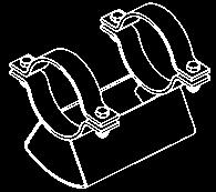

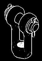


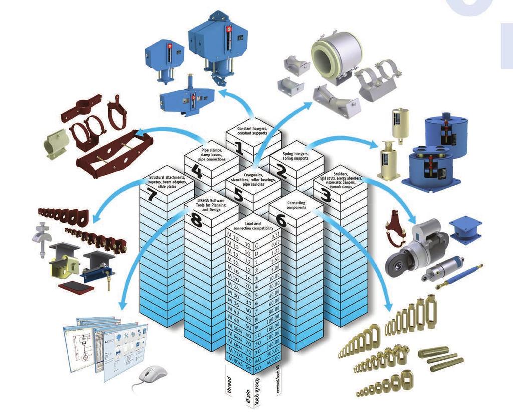
6 Overall contents Detailed information on contents in the individual sections Product group Technical specifications Constant hangers, constant supports Spring hangers, spring supports Snubbers, rigid struts, energy absorbers, viscoelastic dampers, dynamic clamps Pipe clamps, clamp bases, pipe connecting parts Roller bearings, pipe saddles, cryogenic clamp bases Threaded connecting elements Structural attachments, trapezes, clamps, slide plates Plug-in and Libraries LISG software tools for planning and design Supplementary services, engineering, field service 8 9
7 Product group 1 Constant hangers, constant supports, s 11-14, Product group 2 Spring hangers, spring supports, s 20-22, Product group 3 Snubbers, energy absorbers, rigid struts, viscoelastic dampers, dynamic clamps, s Product group 4 Pipe clamps, clamp bases, pipe connecting parts, s 41-46, Product group 5 Roller bearings, pipe saddles, cryogenic clamp bases, s Product group 6 Threaded connecting elements, s Product group 7 Structural attachments, trapezes, clamps, slide plates, s Product group 8 LISG software tools for planning and design Product group 9 Supplementary services, engineering, field service
8 Technical specifications 0 Technical specifications Product 0 group


9
10 Technical specifications Contents Page 1. Standard Supports, requirements and definition LISG Standard Supports LISG Modular System User benefits Functionality Product groups Load groups Travel ranges Standardized component Modular System for load and connection compatibility Permissible loads Statically and dynamically loaded components Product group Product group Load tables Type designation system Standards and codes Materials Welding Surface treatment against corrosion Standard corrosion protection Increased corrosion protection Hot dip galvanized version Operational behavior Connection dimensions Quality Management and IMS Suitability tests, tests Standard versions and increased requirements Form of shipment Warranty Technical modifications PRODUCT0 GROUP
11 Technical specification The products outlined in this catalog Standard Supports 2020 are fully in line with the latest developments in support technology and satisfy general requirements for plant installation at the highest level. For the general design of LISG standard supports, standardized criteria are applied. They are described in the following Technical specifications and apply to the contents of this catalog. Component related features are outlined in the corresponding sections of the product group sections and in the data sheets. Unless expressly agreed otherwise, the stipulations in the catalog Standard Supports 2020 apply to all our shipments Standard Supports, requirements and definition 1.1 Requirements For the support of industrial piping systems the use of standard supports is regarded as well-proven, up-to-date technology. Only a high level of standardization can satisfy the demand for technically superior and economical support components. The complex requirements for modern pipe supports are: reliable functioning maintenance-free operation quick delivery low component prices computerized design systems easy installation favorable performance weight ratio 1.2 Definition Standard supports must fulfill the following criteria: component shapes are uniform and designed to make the optimum use of material components are compatible regarding dimensions and load capacity components are cataloged and clearly designated via an identification system components are manufactured in series production components comply with the approved standards and international codes the functional capacity, suitability and durability of the components is well proven components are certified and approved for use by independent certification bodies The relevant codes for pipe supports in German and uropean plant construction (power stations), the DIN N T3 and VG Guideline R 510 L, require the preferential use of standard supports and define the criteria as follows: Standard Supports are pipe support components in which the design in form and dimensions, as well as the design data regarding loads, are specified, verified and cataloged and where the components are manufactured according to defined, reproducible processes, e.g. series production. 2. LISG Standard Supports 2.1 Scope t LISG, standard supports form the basis of a comprehensive performance package. complete product program of more than 12,000 standardized components covers all support situations, operational loads, temperatures and travel ranges normally experienced in piping systems in industrial plant construction: m 650 C operating temperature for pipe clamps and clamp bases m 400kN nominal load for all mainly statically loaded components m 1000kN nominal load for rigid struts and standard snubbers m 5000kN design load for large-bore snubbers m 900mm travel range for constant hangers m 400mm travel range for spring hangers 2.2 Design features Specially developed components are available for the various support functions. Fundamental design principles were taken into consideration in the design and construction of the components: symmetrical design shapes compact installation dimensions special, reliable functional principles extra-wide adjustment ranges fully compatible load ranges and connection dimensions integrated installation aids Moreover, LISG hangers feature only one upper connection point. Due to this, along with compact and symmetrical design shapes, load distribution free of imposed moments on the connections is ensured and easy installation made possible. The operating position of the moving parts (hangers, supports and snubbers) can be read directly off a linear travel indicator. Load adjustment of the constant hangers and supports can be carried out at all times, even in the installed condition. Hangers and supports can be blocked in any travel position.
12 2.3 Principle of the optimum design For the design and arrangement of support components, optimum coverage of the specific support function is the decisive factor. So only one design is required for each function, namely, the optimum one for the purpose. The project engineer is no longer forced to choose from a range of alternative solutions. This not only facilitates application but also increases safety. In addition it is a prerequisite for the logical implementation of standardized construction according to the modular system. There s only ON best solution! 3. The LISG Modular System 3.1 User benefits The cost of pipe supports is a major factor in the total cost of a pipe system. The cost of the supports is the accumulated total arising from the individual costs of: project management (processing) design and engineering work use of material (components) and installation and assembly work Moreover, the pipe supports are almost always critical for the commissioning deadlines and can, through delays in delivery, cause incalculable extra costs. The goal of the LISG product strategy is to achieve optimum user benefits for customers at the lowest cost, following the economic principle. The LISG modular system provides the corresponding basis. The standardization of components is the decisive prerequisite for: The cumulative benefits from this result in reliable project processing at competitive prices with superior component quality. In addition, the user also benefits from cost reductions in labor-intensive sectors such as support engineering (design) and onsite installation. The assembly procedure for the pipe systems can also be streamlined by first installing the supports, then mounting the piping directly into them. 3.2 Functionality The standardization of components at LISG is specifically directed toward their systematic interaction as support configurations. To this end, load and travel ranges as well as the geometry of the connections are harmonized. The LISG standard support program has been developed in this fashion as a fully functional and effective modular system. The individual components therein form modules and guarantee load compatibility. This enables a wide range of combinations to produce tailor-made support configurations as required. The comprehensive selection of components enables adaptation to widely differing support situations and application conditions. 3.3 Product groups The standardized components are divided into 7 product groups according to task and function (see standardized components table, page 0.3 and diagram on page 0.4). 3.4 Load groups To ensure uniform loading in component combinations the product groups are arranged throughout according to clearly classified static and dynamic load groups (see page 0.5 and page 0.6). 0 The economic principle: = with the least possible effort, achieving the maximum possible benefit = Total Cost Minimum/TCM First install the supports, then mounting the pipes! Product groups + load groups + travel ranges + connection compatibility = Modular System Modular System + CD design + IT Logistics System = High-Tech pplication rational series production favorable performance/weight ratios consistently high product quality ready availability from stock our special LICD design software 0.2
13 a Metric or UNC according to region of application. b For spring hangers and supports (product group 2) the springs are pre-stressed to approx. 1/3 of their nominal load. This results in the initial load. 0.3 Within a load group (nominal load), all components feature uniform load limits and safety margins. Within a load group the connection dimensions of the components (thread a and pin diameters) are uniform and compatible with the components in other product groups. s different components can only be combined with each other within the same load group the stresses on a load chain are consistent throughout, whereby the clamps are selected in each case according to the relevant temperature, load and insulation thickness of the pipe system. The incorrect combination of parts from different load groups is thus avoided. 3.5 Travel ranges Constant and spring hanger travel ranges Moving components such as constant and spring hangers are split into travel ranges corresponding to the usable spring travel of the standard springs used. The relevant travel range in each case is designated in the designation by the 4 th digit in the following table. constant hangers travel range [mm] designation number spring hangers travel range [mm] b designation number Snubber travel ranges The LISG snubbers are grouped into standard stroke ranges denoted by the 4 th digit of the designation as in the following table. snubbers stroke [mm] designation number / / Standardized components standardized components product group unit unit designation 1 Constant hangers & supports 2 Spring hangers & supports 3 Dynamic components 4 Pipe connecting components 5 Pipe bearings and saddle components, cryogenic clamp bases 6 Threaded connecting elements 7 Structural attachment elements 11 Constant hangers Constant hangers, multi-cell 16 Constant supports, multi-cell 17 Servo hangers 18 Constant hangers, low profile 19 Constant supports, low profile 19 ngulating const. supp., low profile 71 rackets for constant hangers 79 Constant hanger trapezes 20 ngulating spring supports 21 Spring hangers 22 Heavy duty spring hangers 25 Spring hangers, seated 26 Heavy duty spr. hang. (seated) 27 Sway braces 28 Heavy duty spring supports 29 Spring supports 72 ase plates 79 Spring hanger trapezes 30 Snubbers 31 Large bore snubbers 32 nergy absorbers 33 Installation extensions 34 Dynamic pipe clamps 35 Weld-on brackets Dynamic pipe clamps 39 Rigid struts 3D Viscoelastic dampers 3L Shear lugs 3R Pipe whip restraints 40 U-bolts 41 Weld-on lugs Horizontal clamps 45,46,48 Riser clamps 49 Clamp bases, lift-off restraints 77 Connection plates 51 Cylinder roller bearings 52 Double taper roller bearings 53 Double cylinder roller bearings 54 Weld-on pipe saddles 54 Pipe saddle with pipe clamps 55 Lift-off restraints 56 Cryogenic clamp bases 57 Cryogenic axial stops 57 Weld-on pipe shoes 58 Stanchions 60 ye nuts 61 Clevises 62 Turnbuckles 63 Hexagon nuts 64 Rod couplings 65 Tie rods L/R 66 Tie rods 67 Threaded rods / stud bolts 70 Sliding components 73 Weld-on clevises 74 Weld-on plates with sph. washers 75 Weld-on eye plates 76 eam adapters 78 eam clamps 79 Trapezes


14 3.7 Modular system for load and connection compatibility 0 0.4
15 Cold load: The cold load is the load determined by the pipe system calculations for the support point in shut down condition. Set load (blocking load): The set, present or blocking load is the load at which the spring or constant hanger is set and blocked. The set load is made up of the cold load and the dead weight of the components suspended from the spring or constant hanger. In part, blanket dead weights are already calculated into the cold loads. These must be taken into account when designing the hanger arrangement. Hot load (operating load): The hot or operating load is the load acting on the support point during normal operation. For spring hangers it is made up of the set load and the force resulting from spring travel multiplied by spring rate. For constant hangers the hot load corresponds to the set load. Hydrostatic test load: The hydrostatic test load is the load acting on the support during pressure testing, in general at 80 C. Pickling (and clean) load: The pickling load is the load distributed from the support points during pickling of the pipe system, in general at 200 C. dynamically defined components product group 3 load group load [kn] Ø pin Permissible loads 4.1 Statically and dynamically loaded components For permissible loads we distinguish between statically and dynamically loaded components. The components in product groups 1, 2, 4, 5, 6, and 7 are, according to their function, loaded in only one direction (static or quasi static) and are viewed as statically determined components. The units in product group 3 as well as their accessories are regarded as dynamically determined components Static components The nominal load is used to denote the load group. For the statically determined components in product groups 1, 2, 6 and 7 the nominal load corresponds to the max. set load of spring elements such as spring hangers. The max. operating load (load case H) is, in the event of use as a rigid support, considerably higher than the nominal load and is adapted to the load capacity of the connection thread. This also includes spring hangers and constant hangers in blocked condition, whereby for cold loads in pressure tests (short duration) the emergency loads (load case HZ) can be exploited. statically defined components product groups 1, 2, 6, 7 load group load nominal Ø connection [kn] thread wrench size Ø pin C 0.31 M D 0.62 M M M M M M M M M M M56x M64x M68x M72x M80x Dynamic components For dynamically loaded components the nominal load corresponds to the operating load for load case H (under normal conditions) or level /. (SM III / RCC-M). s these components are generally used as safety devices for emergencies, load case HZ or level C (SM III / RCC-M) are taken as the maximum occasionally occurring load condition. In any case, the requirements set forth by the responsible project engineer apply. 4.2 Product group 4 For product group 4 (pipe connections), a corresponding overlapping area in the load groups is taken into account, due to the wide temperature-dependent range of different loads. Data on the permissible loads for pipe-connecting components under consideration of the respective operating temperatures can be taken from the individual selection tables. The permissible operating loads for long-term operation (load case H (under normal conditions), normal load, level ) are shown here. On higher short-term loading (e.g. hydrostatic tests) no permanent deformation is caused. The permissible loads in load cases HZ (emergency (occasionally occurring operating conditions), level C) and HS (faulted condition, level D) depend on the codes to be complied with. examples code load case HZ (emergency) load case HS (faulted condition) SM section III, NF H x 1.5 H x 1.6 RCC-M H x 1.33 H x 1.6 MSS SP-58 H x 1.2 no data DIN N H x 1.2 no data VG-R 510 L a H x 1.15 H x 1.5 KT a H x 1.15 H x Product group 5 The components in product group 5, clamp bases for cold pipe systems, low temperature systems (cryogenic) as well as roller bearings and pipe saddles, are regarded as static, however they are not considered to be part of the modular system with regard to the load group. s they are more comparable with components in secondary steelwork with respect to loading, they form a separate group. The nominal load here corresponds to the max. operating load according to load case H (normal operation conditions level /). For product group 5 see also 4.4.3, page 0.6. a For components according to KT 3205 qualification test the following applies: HZ = H x 1.5; HS = H x 1.7
16 4.4 Load tables The permissible loads of the components are arranged in the form of a matrix (ordered according to load groups and load cases) in the following LISG load tables. The definition of the load cases are in line with DIN N T3, VG-R 510 L, SM 31.1, MSS SP-58, SM Max. for statically determined components normal operation c emergency d faulted condition e load nominal level / upset level C level D group load [kn] a b 80 C 150 C 80 C 150 C 80 C 150 C C D Max. permissible loads [kn] for dynamically determined components, product group 3 normal (F N ) / upset f emergency g faulted condition h load level / level C level D group 80 C 150 C 80 C 150 C 80 C 150 C i Max. permissible loads for roller bearings in product group 5 section III, Div. 1, Subsection NF and KT The load table applies uniformly to all components in the LISG modular system and to other LISG components scheduled for use with standard components such as special designs Max. permissible loads for viscouselastic dampers 0 a Max. operating load for spring and constant hanger corresponding to max. load on main springs. The load group allocation does not apply to s 18/19. b Permissible loads according to design criteria for US standard MSS SP-58 (SM 31.1 / 31.3). c ll loads are included here that can possibly occur during conventional operation of the plant, including startup and shutdown, weight tolerances, and hydrostatic tests. d Loads falling outside conventional operation are included here, according to the regulations in each case, also hydrostatic tests. Subsequent inspection of the whole support arrangement is strongly advised. e Due to the loads specified the yield stress of the components can be reached. t all events replacement is recommended. f ll dynamic stresses possibly resulting from plant operation are included here including pressure shock forces from valve operations or possibly from operating basis earthquakes (0...). g ll dynamic stresses beyond conventional operation and possibly safety shutdown earthquakes (S.S..) are included here. Subsequent inspection of the whole support arrangement is strongly recommended. h For the dynamic loads specified the yield stress of the components can be reached. t all events replacement is strongly recommended. i Load groups 1 and 2 are compatible regarding load and connections, whereby load group 1 refers to the smallest snubber and load group 2 to the corresponding rigid struts and weld-on brackets. permissible loads [kn] normal operating conditions occas. occur. operat. cond permissible loads [kn] 3D.... -D D.... -L
17 5. Type designation system ll components can be identified via coded designations. 6 digits contain all the information required for description of the standard design. The designation system is the prerequisite for the use of modern IT and enables the unrestricted integration of the LISG modular system into current CD programs. The LISG designations can be decoded by way of the following tables. The 1 st digit describes the product group (PG) PG 1 = Constant hangers and supports PG 2 = Spring hangers and supports PG 3 = Dynamic components PG 4 = Pipe connecting components PG 5 = Pipe bearings and saddle components, cryogenic clamp bases PG 6 = Threaded connecting elements PG 7 = Structural attachment elements The digits 2 6 designate the further characteristics according to the following tables. The design for increased requirements (5 th or 6 th digit) is described on page PG 1 Constant hangers and supports 2 nd digit 3 rd digit 4 th digit 5 th digit 6 th digit design 1= constant hanger 2= CH 2 x coupled 3= CH 3 x coupled 4= CH 4 x coupled 6= heavy con. support 7= servo hanger 0.7 load group C=M10 D=M10 1=M12 2=M12 3=M16 4=M20 5=M24 6=M30 7=M36 8=M42 9=M48 8=LG10 9=LG20 8=LG30 9=LG40 8=LG40 9=LG50 8=160kN 9=200kN 8=240kN 9=300kN 8=320kN 9=400kN 5=M24 6=M30 7=M36 8=M42 9=M48 *S= sliding element travel range [mm] 2=150 3=300 4=450 5=600 6=750 7=900 2=150 3=300 2=150 3=300 field of application 1= standard 5= standard <increased requirements> production series 3=2013 5=1985 9=1999 3= standard 5=1985 4= standard with brackets 7= standard <increased requirements> 8= standard with brackets <increased requirements> 2= coupled 2 x 6=with high temp. S* 7=with 3= coupled 3 x PTF-S* 9=without 4= coupled 4 x S* 1= standard 5= standard <increased requirements> 5=1985 PG 1 Constant hangers and supports (continued) 2 nd digit 3 rd digit 4 th digit 5 th digit 6 th digit design load group travel range [mm] field of application production series 8= constant hanger, short 9= constant support, short 9= angulating constant support, short PG 2 Spring hangers and supports 2 nd digit 3 rd digit 4 th digit 5 th digit 6 th digit design load group travel range [mm] field of application production series 1= spring hanger suspendet 0= angulating spring support 0= installation extension for 20 5= seated 7= sway brace 7= installation extension for 27 9= spr. support C=M10 D=M10 1=M12 2=M12 3=M16 4=M20 5=M24 6=M30 7=M36 8=M42 9=M48 2= heavy spring 1=LG 10 hanger 2=LG 20 suspended 3=LG 30 6= heavy spring 4=LG 40 hanger seated 5=LG 50 8= heavy spring support 1= 50 2=100 3=200 4=300 5=400 9=installation xt. f. 20 & 27 & 29 1= 50 2=100 3=200 2= standard 6= standard <increased requirements> 1= standard 5= standard <increased requirements> 2= telescopable spring support 6= <increased requirements> 1= standard 5= standard <increased requirements> 2= standard 6= standard <increased requirements> PG 3 Dynamic components 1=1991 4=1994 8=1978 9=1999 1=1991 4=1994 6=with high temp. S* 7=with PFT-S* 8=1978 9=1999 9=1999 6=with high temp. S* 7=with PFT-S* 2 nd digit 3 rd digit 4 th digit 5 th digit 6 th digit design load group travel range [mm] field of application production series 0= hydraulic snubber serial version 2= energy absorber 3= installation extension 1= hydraulic snubber large bore 5= weld-on bracket D=M10 1=M12 2=M12 3=M16 4=M20 5=M24 6=M30 7=M36 8=M42 9=M48 1= 3 2= 4 3= 8 4= 18 5= 46 6= 100 7= 200 8= 350 9= 550 0= = = = = = 550 0= = 75 2= 150 3= 300 2=150 3=300 4=400 5=500 8=100 9=200 8=100 9=200 19= 3 79= = 4 89= = 8 99= = 18 09= = 46 20= = 100 1,2= standard 7=2007 5,6= <increased requirements> 1,2= standard 6=with constant support high 3,4= standard temp. angulating S* constant support 7=with 5,6= support PTF- <incr. requirem.> S* constant support 7,8= <increased 7=2007 requirements> angulating constant support 1= standard 5= standard <increased requirements> 1= standard 5= standard <increased requirements> 2=2002 3=1993 6=1986 8=1988 at 32: 6=1996 1=1991 3=1993 9=1989 PG 3 Dynamic components (continued) 2 nd digit 3 rd + 4 th digit 5 th digit 6 th digit pipe diameter field of production design load group [kn] application series 6= dynamic pipe clamp with U-bolt Pipe diameter in [mm/10] 1 3= 1 x U-bolt 4 5= 2 x U-bolt 7= dynamic clamp with strap 9= rigid strut 2= 4 3= 8 4= 18 5= 46 6= 100 7= 200 8= 350 9= 550 0= 1000 T0=1016 T1=1067 T2=1118 T3=1168 T4=1219 standard 1=to 350 C 2=to 500 C 3=to 560 C 4=to 600 C standard <increased requirements> 6=to 350 C 7=to 500 C 8=to 560 C Middle installation dimension in mm/ = 1 x Strap 7 9= 2 x Strap L= shear lug 3 rd to 6 th digit corresponds to clamp 2 4= standard 7 9= <increased requirement> 2 nd digit 3 rd + 4 th digit 5 th digit 6 th digit travel vertical travel horizontal design load group [kn] [mm] [mm] D= viscouselastic damper 03 = = = 5 40 = = = = = = = = 25 H1 = 100 3=30 4=40 5= D = depend l = limit 3=30 4=40 5=50 PG 4 Pipe clamps, clamp bases and pipe-connecting components 2 nd digit 3 rd + 4 th digit 5 th digit 6 th digit load group field of production design pipe diameter application series 1= weld-on lug 1=standard horiz. clamp 2= 1-hole 2= 2-hole 3= 3-hole 4= with U-bolt or strap riser clamp 5= formed riser clamp 6= box clamp for shear lugs 8= box clamp for trunnions D9= LGD 29= LG2 39= LG3 49= LG4 59= LG5 69= LG6 79= LG7 01= = = = = = = = = = = = = = = = = = = = = = = = = = = = = = = = = = = = T0= 1016 T1= 1067 T2= 1118 T3= 1168 T4= =standard standard 1=to 350 C 2=to 500 C 3=to 560 C 4=to 600 C 5=to 650 C standard <increased requirements> 6=to 350 C 7=to 500 C 8=to 560 C for straight pipes max. insulation thickness in mm 1=10 2=100 for pipe elbows RP1.5OD max. insulation thickness in mm 3,4=10 5,6=100 depending on load group and design
18 PG 4 Pipe clamps, clamp bases and pipe-connecting components (continued) 2 nd digit 3 rd + 4 th digit 5 th digit 6 th digit pipe diameter field of design [mm] application production series 9= clamp base 01= = = = = = = = = = = = = = = = = = = = = = = = = = = = = = = = standard 1=to 350 C 2=to 500 C 3=to 560 C 4=to 600 C 5=to 650 C standard <increased requirements> 6=to 350 C 7=to 500 C 8=to 560 C 0= U-bolt 81= = = = = S235R T0= 1016 T1= 1067 T2= 1118 T3= 1168 T4= = lift-off restraint for clamp base 00= lift-off restraint 3= <incr. requirem.> 6= S235R 8= = lift-off restraint 1= low 2= medium 3= low, welded 4= medium, welded 5= high, welded 8= standard 1 5= compon. size PG 5 Roller bearings, pipe saddles and cryogenic clamp bases 2 nd digit 3 rd + 4 th digit 5 th digit 6 th digit load group [kn] field of production design pipe diameter application series 1= cyl. roller 04= 4kN 1= standard 9=1989 bearing 08= 8kN 2= movable 2= double taper roller bearing 3= double cyl. roller bearing 5= lift-off restraint for roller bearing 12= 120kN 16= 16kN 35= 35kN 60= 60kN laterally 4= pipe saddle with pipe clamps, weldon saddle, pipe tray 6= cryogenic clamp base 7= cryogenic axial stop 7= weld-on pipe shoe 01= 21.3mm 02= 26.9mm 03= 33.7mm 05= 48.3mm 06= 60.3mm 07= 73.0mm 08= 76.1mm 09= 88.9mm 10=108.0mm 11=114.3mm 13=133.0mm 14=139.7mm 16=159.0mm 17=168.3mm 19=193.7mm 22=219.1mm 24=244.5mm 26=267.0mm 27=273.0mm 32=323.9mm 36=355.6mm 37=368.0mm 41=406.4mm 42=419.0mm 46=457.2mm 51=508.0mm 1= weldable 2= with pipe clamps 3= support plate Length: 3=150mm 5=300mm 7=500mm 8=750mm 8= stanchion 1= rigid pipe 56=558.8mm supports 61=609.6mm 2= pipe 66=660.4mm supports, 71=711.2mm adjustable 76=762.0mm 81=812.8mm 91=914.4mm 97=965.2mm Insulation thickness in mm 0= 25 1= 40 2= 50 3= 80 4= 100 5= 130 6= 150 7= 180 8= 200 9= 250 1= Standard 1= out of T-section 2= out of U-section 1,2=for str. pipes 3,4=for elbows R P OD 5,6=for pipe elbows R P 1.5 OD PG 6 Connecting components 2 nd digit 3 rd + 4 th digit 5 th digit 6 th digit design field of load group application production series 0= eye nut 1= clevis 2= turnbuckle 4= rod coupling 1= standard 5= standard <increased requirements> 2=1982 5=1995 8=1978 9=1999 Type designation xamples D9= M kN 29= M kN 39= M kN 49= M kN 59= M kN 69= M kN 79= M kN 3= hex. nut 2= standard 89= M kN 3= 25CrMo4 99= M48-100kN 5= standard 10= M56x4-160kN <increased 20= M64x4-200kN requirements> 30= M68x4-240kN 40= M72x4-300kN 50= M80x4-400kN 5= tie rod L/R 6= tie rod R/R 7= stud bolt, threaded rod D=M10 2=M12 3=M16 4=M20 5=M24 6=M30 7=M36 8=M42 9=M48 10=M56x4 20=M64x4 30=M68x4 40=M72x4 50=M80x4 Length: 0= LG10 - LG50 1=stud bolt 2= 500mm 3=1000mm 4=1500mm 5=2000mm 6=2500mm 7=3000mm Length not standardized 1= standard 5= standard <increased requirements> 3=1993 8=1978 9=1999 Production series/travel/variant Field of application/travel Travel range/pipe Ø/function Load gr./pipe Ø/thread Ø Design Product group (PG) 1985 Standard design Travel range 3 / 0-300mm Load gr. 5 / F N = 20kN Individual design Constant hanger High design, welded 13CrMo4-5, increased requirements Pipe diameter 508mm Clamp base Pipe connection Standard design Medium length 2500mm Load group 6 / F N = 100kN Rigid strut PG 7 Structural attachments and trapezes 2 nd digit 3 rd digit 4 th digit 5 th digit 6 th digit load field of design group function application production series 0= sliding elements 1= support bracket for constant hanger 1= support bracket for heavy constant hanger 2= base plate for spring hanger 3= weld-on clevis 4= weld-on plate 5= weld-on eye plate 6= beam adapter & combinations Width 1= 50 2= 100 3= 150 4= Length 1= 50 2=100 3=150 4=200 6=300 7=390 8=490 05=Ø 50 13=Ø =Ø 85 17=Ø =Ø =Ø 200 C 9= load group 8=160kN 9=200kN 8=240kN 9=300kN 8=320kN 9=400kN 2=150 3=300 4=450 5=600 6=750 7=900 D 9= 1, 2, 3, 9= load group dep. on design 1= welded 2= bolted, hot dip galvanized 3= bolted, hot dip galvanized 1= rectangular, up to 180 C 4= rectangular, up to 350 C 2= round, up to 180 C 5= round, up to 350 C 6= standard 1= single 8= standard support <increased requirements> 2= coupled 2 x 3= coupled 3 x 4= coupled 4 x 2= standard 8= = standard <increased requirements> D 50= 0 L 1= standard load group load group 9 2= lift-offrestraints 5= standard <increased requirements> D 4= size C 2= size 00=guide 2= beam adapter & bolts 1= cantilever 2= = = = = vertical connection 7= horizontal connection 1...4= size 8= beam clamp 2..7= load 1= standard 1= 1991 group 9= constant hanger trapeze 9= spring hanger trapeze 9= rigid trapeze 7= connecting plate 3 rd to 5 th digits correspond to 3= 2013 single hangers in each case (see PG1) 5= = rd to 5 th digits correspond to single hangers in each case (see PG2) C 4= 2,3= load group depending 2 9= load group 2 20= load group on design 0 L LG9 3= standard 8= standard <increased requirements> 1= welded unit 9= with individual hangers 7= L-section 9= U-section, centric connection 4= U-section 3 rd to 6 th digit correspond to the clamps to be coupled Strap clamp for heavy loads Material 10CrMo9-10 standard design Pipe diameter 609.6mm Horizontal clamp, U-bolt or strap Pipe connection 0.8
19 Worldwide coverage of recognized standards 6. Standards and codes In design, in stress and load calculations, as well as in production, the relevant uropean and other international standards are taken into account. The material characteristics upon which all design calculations are based are taken from the relevant standards and technical codes. the following codes apply: DIN N T3 Metallic industrial pipe systems urope VG-R 510 L Standard supports Germany KT /2/3 Nuclear regulations Germany D-Merkblätter Pressure vessels working group Germany RCC-M Specifications for pipe supports France MSS SP-58 Pipe supports material and design US NSI SM 31.1 / 31.3 Pressure piping systems US SM section III Div. I - NF Supports for nuclear components US SM S NC1 Nuclear design code apan G 4601 Nuclear design guide apan SPIR-O-2008 Supports for nuclear plants for S-2006 Russia 7. Materials Materials are exclusively used that conform to DIN-N, STM or CN steel material requirements. s a matter of course only materials of guaranteed strength characteristics are used for the support components. Preferred materials for pipe connections Standardized selection of carbon steels and heat-resistant materials! High temperature resistant materials for use at higher temperatures or cold tough materials e.g. until 60 C on request. temperature of medium in C DIN-N STM CN-Steel m350 m450 m500 m530 m560 m600 m650 S235R 36 Q235 x S235R 516 Gr. 60 x S235R 675 Gr. 55 x S Gr. 70 Q345/Q345R x S Q345/Q345R x S Gr. 70 Q345/Q345R x P235TR1 53 S Gr. 20G x P235GH 53 S Gr. 20G x P355NH 106 Gr. C 20G x 16Mo3 204 (Q345R)/15CrMoR x x x 13CrMo Gr. 12 Cl.2 15CrMoR x x x x x 10CrMo Gr. 22 Cl.2 12Cr1MoVR/12Cr2Mo1R x x x x x x X10CrMoVNb9-1+NT/QT 387 Gr. 91 Cl.2 x x x x x x x X5CrNi TP Cr19Ni10 x x x x 42CrMo4+QT CrMo x x x x x x x x X10CrMoVNb9-1+NT/QT 182 F91 x x x x x x x 21CrMoV5-7+QT 25Cr2MoV x x x x x 25CrMo4+QT 194 Gr. 2H 25Cr2MoV x x x x x 0.9
20 0 8. Welding ll welding is carried out as gas metal arc welding under protective gas according to DIN N ISO MG/GMW (= gas metal arc welding), Procedure no. 135 MG/FCW (= flux core arc welding), Procedure no. 136 WIG/GTW (= gas tungsten arc welding), Procedure no. 141 For these procedures (welding procedure specifications (WPS)) are on hand which are certified on the basis of the N ISO and / or SM section IX (WPQR). The welders are qualified according to N and SM section IX for the corresponding procedures and material classes, and the service personnel for welding equipment according to N 1418 and SM section IX. LISG holds certifications according to: DIN T7 Kl., recertification according to N X 4 conformity certification for support components and N Technical regulations for the execution of steel construction SM section III Div. I Subs. NC 4000 NPT and NS stamp N ISO TRD 201/D 2000 Leaflet HPO Technical Regulations for Steam oilers/ Manufacture and inspection of pressure vessels by the German TÜV Non-destructive testing VT, PT, MT, UT and RT (external) is conducted by test personnel qualified according to standards ISO 9712 Level II and SNT-TC-1 Level II. Supervision is carried out by personnel qualified according to ISO 9712 Level III and SNT-TC-1 Level III. The tests are conducted on the basis of regulations: N ISO 5817 ssessment Group C N ISO (ISO 10836) with relevant stipulations for the various ZfP procedures RCC-M Subs. H 4000 with MC 3000 MC 7000 SM section V as required by subsection NF 9. Surface treatment against corrosion s a matter of principle, LISG products are designed for long-term operation, functioning reliably for the whole life of the plant. To limit maintenance work, particular attention is paid to protection against corrosion. It is important to specify the of surface treatment for the environmental conditions prevailing. LISG offers a range of suitable corrosion protection systems based on the corrosivity categories and protection periods of N ISO 12944: Standard surface protection (9.1) Increased surface protection (9.2) Hot dip galvanized version (9.3) Surface protection for extreme applications (9.4) The current welding inspection team is qualified according to: N ISO 14731, welding engineers IW and W (International/uropean welding engineer) and welding technicians, IWS (International Welding xpert) Certified welding inspectors according to WS 1.1 SM section III Div. I Subs. NF-5500 SNT-TC
21 Wherever technically feasible, LISG uses low-solvent, environmentally friendly, water-borne paint finishes. Data on specified coat thicknesses correspond to NDFT (Nominal Dry Film Thickness) according to DIN N ISO 12944, measured according to DIN N ISO Standard corrosion protection s protection against corrosion, the surfaces of LISG products are treated with high-quality protection systems. Our standard corrosion protection corresponds to the Corrosion Category C3, medium protection period (M) according to N ISO and is well suited to implementation in environments with a moderate industrial atmosphere. Typical fields of application in this regard are the interiors of production workshops with increased levels of humidity and dust or exteriors with a normal atmosphere Standard paint finish Metallic surfaces of carbon steel exposed to the open air receive shotblasting to S 2 1 /2 (SP10 according to STM) and then a base of zinc-rich primer 60µm is applied. fter curing an additional top coating 60µm is applied. The total dry film thickness of the coating amounts to 120µm, color shade RL 5012 light blue. Components falling into this category are constant hangers and supports, heavy spring hangers and supports, trapezes, installation extensions for snubbers etc., rigid strut tubes and viscoelastic dampers Cathodic electrophoretic dip coating of springs (CD) High quality helical coil springs are an important element in LISG constant and spring hangers. Due to their exposed functional significance, all springs are treated with a cathodic electrophoretic dip coating (CD). The springs are shot-blasted and zinc-phosphated on their extended or peeled surfaces. Finally, a dual-component epoxy resin coating is applied in a galvanic process and baked at approx. 200 C lectro galvanizing Spring hangers and spring supports, beam clamps and all threaded components and internal functional parts of the constant hangers and supports are galvanized with a coating thickness of approximately 12 15µm Hot dip galvanizing Roller bearings, pipe saddles and cold-block clamp bases are treated as standard with hot dip galvanization, coat thickness 60 80µm Primer coating Due to their special installation situation, mainly within the insulation, the pipe-surrounding components such as pipe clamps and clamp bases, weld-on brackets, weld-on eye plates, weld-on clevises, weld-on bearings and weld-on pipe supports (stanchions) are treated to higher quality transport protection with a weldable primer coating on a shot-blasted surface, coat thickness approximately 30µm, color shade red brown Snubbers Snubbers are manufactured completely from corrosion resistant materials and require no special coating. The separate connection lugs of 30, are manufactured from carbon-steel, and treated according to Snubber connections Connecting lugs are electro galvanized according to and fitted with corrosion-protected ball bushings. Installation extensions are treated with the standard paint coating according to Weld-on brackets are given a weldable primer coat according to and the connection pins are of stainless steel Rigid struts The rigid strut tubes are given a standard color coating (9.1.1). The ball bushing joints are electro galvanized (9.1.3) and fitted with corrosion-protected ball bushings. Weld-on brackets are treated with a weldable primer coating (9.1.5), while the connecting pins are stainless steel. 0.11

22 9.2 Increased corrosion protection Increased corrosion protection according to N ISO 12944, Corrosivity Category C4, medium protection period (M), is recommended in aggressive atmospheres, such as in the open in industrial areas and in coastal regions with moderate saline exposure or in the case of internal applications in chemical plants. Increased corrosion protection is ensured through corresponding additional measures for surface treatment according to to on the basis of the standard treatment Increased corrosion protection for carbon steel surfaces Painted surfaces corresponding to the standard version (9.1.1), such as constant hangers and supports, support brackets, trapezes, installation extensions, rigid strut tubes and viscoelastic dampers are topcoated with an additional coat of 60µm on an already existing coat of 120µm, so that a specified coat thickness of 180µm is achieved, color shade RL 5012 light blue. Functional components lying within the constant hanger bodies are also treated according to corrosivity category C4, medium protection (M), in line with N ISO Increased corrosion protection for electro galvanized surfaces Surfaces electro galvanized as standard according to 9.1.3, such as spring hangers and supports, are given a layer of adhesion primer of 40µm thickness plus a topcoat of 60µm to create a total layer thickness of 115µm, color shade RL 5012 light blue. Threaded parts from product group 6 are not given additional surface coats and can if required be supplied hot dip galvanized Increased corrosion protection for spherical bearings The connecting elements of rigid struts and snubbers receive a special coating containing zinc and aluminum lamellas with an additional organic topcoat, layer thickness approx µm Increased corrosion protection for LISG helical coil springs On top of the standard CD coating according to a supplementary paint layer with a specified thickness of 60µm is applied Increased corrosion protection for pipe clamps and clamp bases, product groups 3 and 4 Pipe clamps and clamp bases for an application range up to 350 C can, if required, be supplied hot dip galvanized. application range [] up to 350 C [ / ] [ / ] Pipe clamps and clamp bases for a range over 350 C are given a coating which corresponds in the stability of its maximum working temperature to the following table. application range [] over 350 C [ / ] [ / ] [ / ] [ / ] [ / ] [ / ] thylsilicate coating outside the insulation coating for increased corrosion protection hot dip galvanization coating for increased corrosion protection within the insulation: Primer (as transport protection) Coat thickness approx. 30µm outside the insulation: thylsilicate coating Specified coat thickness 80µm Insulation Coating in example of pipe clamps, insulated at T L 350 C Primer coating inside the insulation 0 Threaded parts and boltings of the straps, plates, U-bolts and clamps of the pipe-surrounding components must, for increased corrosion protection and a working temperature over 350 C, be located within the insulation in accordance with the installation instructions. The pin connection of pipe clamps and the end plates of the LISG vertical clamps with the adjoining components of the product group 6 must be located outside the insulation. 0.12

23 9.3 Hot dip galvanized version s an alternative to 9.2, all components in the LISG product program can also be supplied as hot dip galvanized version or, where this is not suitable for technical reasons, made from corrosion resistant materials. Components receive a hot dip galvanized coating of approx µm. Internal functional components, threads, small parts etc. are hot dip galvanized by spin coating and have a thickness of approximately 40µm. For components not suited to hot dip galvanization due to the material used or the application area, the version Increased corrosion protection C4 corresponding to 9.2 represents a good alternative Constant hangers and supports, product group 1 If required, constant hangers and supports can be supplied hot dip galvanized. When ordering it should be stated whether corrosion protection C3 according to 9.1 is sufficient or C4 according to 9.2 is required. The difference consists in the additional treatment of the inner functional components Pipe clamps and clamp bases, product group 3 and 4 See section Components in product group 5 Roller bearings, cryogenic clamp bases and pipe saddles are supplied in hot dip galvanized versions as a standard Components in product group 6 Connecting rods and other connecting components, tie rods and threaded rods, threaded clevises, threaded eye nuts, turnbuckles and couplings can be supplied ex stock in hot dip galvanized versions. 9.4 Surface protection in extremely aggressive atmosphere For use in extremely aggressive atmospheres such as e.g. seawater, offshore or aggressive chemical vapors, well-tested corrosion protection systems suitable for all conditions or correspondingly high corrosion resistant materials can be supplied Components in product group 2 Spring hangers and supports are available ex stock in hot dip galvanized versions. 0.13
24 10. Operational behavior 10.1 Function Constant hangers / supports Constant hangers and constant supports of the product group 1 are designed, so that in theory, minimum load deviation occurs over the whole operating range. The total deviation arising from springs, bearing friction and production tolerances is restricted to w 5% in series production. Load adjustment is made to an accuracy level of 2%. load F constant hanger s N F max F min travel s F N F min F max s N 0 = nominal load = minimum load (upward travel) = maximum load (downward travel) = nominal travel (incl. reserve) Spring hangers / supports For spring hangers and spring supports in product group 2 the load changes linearly in line with the spring travel. The deviation of the spring hysteresis from theoretical values, which results from spring hysteresis and production tolerances, amounts to less than w 5% within the operational travel. F H F C load F spring hanger s N perm. tolerance range s travel s 1.05 F N F N 0.95 F N F N = nominal load s N = nominal travel (incl. reserve) F H = hot load a (operating load) for downward operational travel F C = cold load a (installation load) s = operational travel Snubbers Snubbers are designed, in the event of an impact load between the component to be secured and the building structure, to produce an instantaneous rigid connection. Slow displacement due to thermal expansion must not be resisted. Hence the locking mechanism that blocks the component reacts to velocity. The individual functional data are specified in section 3, page 3.7. snubbers s a = piston rod tolerance s b = piston rod travel load F travel s s a s b Viscoelastic dampers Viscoelastic dampers are employed to reduce operational vibrations from machines or plant components to a harmless level by means of broadband damping. The kinetic energy is thereby transformed into heat via a viscous mass. The damping resistance in all degrees of freedom is decisive for its effectiveness. The individual functional data are specified in section 3, page viscoelastic damper load F s b dissipated energy travel s s b = operational stroke Slide plates Slide plates are used to reduce the lateral forces produced by the change in position of the sliding bearing-points. In the LISG slide plates, lowfriction materials are used with self-lubricating characteristics that reduce friction forces by up to 2/3 at an operating temperature of max. 350 C. The individual design data are given in section 7, page reduced friction force load F µ=0.3 µ=0.1 travel s without sliding components with sliding components Reduction in reaction forces in the piping system by the use of slide plates. 0.14
25 [%] Simple method for checking the installation possibilities with the dimension! X = Thread depth t = Total installation dimension (t= total ) a = Length adapted to individual installation conditions 10.2 Spring relaxation When under loading and depending on time and temperature, standard helical compression springs lose a considerable amount of their internal stress through relaxation or settling loss. If no special measures are taken to counter this, in constant and spring hangers, it can in the long-term lead to a reduction of more than 10% in the set ultimate load. In contrast to common practise, LISG exclusively uses specially treated springs that exhibit practically no relaxation. In these springs the expected settling loss is anticipated through hot setting. This method is called prerelaxation. 11. Connection dimensions 11.1 Installation dimension For the simple determination of the required rod lengths in load chains, the installation dimension is specified for all components apart from tie rods and threaded rods (product group 6). This dimension denotes the respective installation length of the components minus the thread engagement depths (X dimensions) of the connecting tie rods and threaded rods. The length of the rods required is given by the total installation height (pipe axis to reference edge of connection surface) minus the sum of the dimensions of the components to be connected. To determine the total length of the rods in a load chain all the dimensions are added together. The sum is compared with the total installation dimension. If a difference results which is greater than the sum of the thread engagement depths (X dimensions), then the chain selected is correct for the total installation height. For load chains solely with pinned connections the minimum installation dimension results from the sum of all dimensions. Product-related details are to be found in the selection tables. relaxation shear stress Relaxation behavior of helical coil springs cold set helical coil springs (loosely based on DIN 2089) LISG hot set helical coil springs, qualified by the KT qualification tests and VG tests [N/mm 2 ] components (extract) reference basis for installation dimension product group 1 constant hangers constant supports servohangers product group 2 spring hangers spring supports (without ) product group 3 snubbers viscoelastic damper product group 4 pipe clamps product group 6 threaded connections product group 7 structural attachments upper starting position (0 on travel scale) on deviation in blocking position to the new blocking position is also to be considered upper starting position (0 on travel scale) on deviation in blocking position the blocking position is also to be considered upper starting position (0 on travel scale) independent of blocking position due to adjustment available in the support tube specification of min and max corresponding to possible travel for installation instructions the planned installation position incl. travel reserves is to be taken into account middle position distance from pipe axis to pin connection or bottom of clamp bases middle line of pin or lower edge of thread engagement depth up to upper edge of thread engagement depth middle line of pin up to face of structure 0.15
 is ensured.")
26 11.2 Regulation of total installation length Turnbuckle function of connection threads For length adjustment in installed condition (setting pipe installation position, creating force-fitting) the lower connections on the constant and spring hangers are designed to function as turnbuckles. In this way convenient future adjustment of installation lengths (connecting rods) is ensured. The length adjustment amounts to: 300mm for constant hangers mm for constant hangers 18 the adjustment possibilities of a 62 turnbuckle for spring hangers 21 min. 140mm for spring hangers 22 for spring hangers s 25 and 26 the load-bearing rods are led through the weld-on support tube and held by an adjusting nut. djustment can be made within the scope of the available thread length of the rods. ll connecting threads are right-hand Constant and spring supports For s 19, 16, 28, and 29, the installation height is adjustable independently of the respective presetting by using the threaded support tube designed as a spindle. The necessary load is reached during installation by the turning of the threaded support tube Turnbuckles 62, tie rods L/R 65 For rigid hangers with short installation lengths a defined reserved length for connection components s 60 and 61 usually enables sufficient length adjustment. For greater installation lengths the use of a turnbuckle L/R 62 in combination with a tie rod L/R 65 is recommended for the purpose of simpler adjustability. For easy accessibility this combination should always be placed at the lowest end of the load chain Rigid struts 39 The connections for the rigid struts 39 are supplied as standard as right/left fine thread for length adjustability in installed condition. Flat faces on the rigid strut body enable easy adjustment with an ordinary wrench. Further instructions are given in the corresponding installation instructions. 12. Quality Management and IMS For the effective management and supervision of the organization (Corporate Governance) the Integrated Management System (IMS) summarizes in a centralized structure the established methods and regulations in the company for observation of the demands in the main sectors. The IMS covers the areas: fundamental company principles quality management environmental protection work and health protection organizational procedures international export certification Through the utilization of synergies and the pooling of resources, lean and effective management is possible. In IMS the data from the various systems are gathered, analyzed and evaluated centrally according to the requirements of modern CQ (Computer-aided quality) solutions. The system takes into account recognized standards and guidelines including the corresponding reporting system. Relevant approvals from authorized bodies can be found in the table on page Quality management Our quality management (QM) monitors and regulates all activities affecting quality in the company. The independent QM department is the leading system in IMS and has overall supervision of the clearly targeted function of the processes integrated into IMS and the observation of rules and regulations. One of the most important corporate principles at LISG is superior product quality, a vital element which also encompasses the activities and close partnership with our business partners. The organization and behavior of our personnel are correspondingly attuned to this. The particular measures ensuring quality undertaken by QM are outlined in the quality management program (QMP), which covers the whole organization. These measures and activities to promote quality are an integral component in the processing cycle and are firmly rooted in the procedures. 0 Constructive devices available for the subsequent adjustment of installation lengths! Constant hanger 11 max min Spring support 29 Turnbuckle 62 Rigid strut 39 The QMP, as an integral component, forms an entity with the processing cycle! 0.16
27 Following international codes and standards, the QMP is described in detail in the Quality Management Manual (QMM). The QMM takes into account all the recognized uropean and other international standards, especially DIN N ISO 9001 and SM section III Div. 1 Subs. NC 4000 including Subs. NF and KT 1401, RCC-M H. The QMM covers the whole organization of the LISG Group and is applied generally both in the conventional sector as well as in areas with increased requirements, such as the nuclear industry. The scope of the traceability of material, and testing the corresponding documentation can also be adapted exactly to special demands by the activation of further verification levels. ll international requirements, including those affecting the nuclear field, can be covered by the QMM. The relevant approvals are available and are regularly renewed Raw material and goods reception ll the materials used are monitored by way of a receiving inspection check by quality management regarding compliance with the technical specifications. The materials used are, according to requirements, certified by material test approvals according to SM and DIN N Production supervision The supervision of production is carried out through constant quality control according to QMM. In particular, for nuclear applications the international quality stipulations according to the codes SM section III NF / NC 4000 (US), RCC-M section H (FR), KT (D), DIN N T5 and NNS (CN) are fulfilled Final inspection efore shipment, constant hangers and spring hangers, as well as snubbers and dampers are subjected, under the responsibility of Quality Management, to function tests on special test benches. The measurement and testing is performed with correctly calibrated test and measurement equipment. The measurements are recorded and can if required be accessed and documented. ll the testing faculties are regularly inspected and checked by qualified personnel according to N ISO Documentation on delivery If required, the materials used are documented by certification via material tests according to SM and DIN N In addition, the results of the functional test can be confirmed by the issue of an acceptance test certificate, also by an independent test institute if so desired. Computerized verification in line with special requirements and special quality-related documents can be agreed upon between customer, producer and supervisor. 13. Suitability tests, tests For the use of serially produced standard supports in industrial piping installations, especially in plants with more stringent requirements, e.g. nuclear power stations, special suitability and tests are required worldwide. The test programs specified mainly involve the following steps: inspection of the quality management program inspection of the materials used inspection of the design documentation verification of the computer-based tensile stress values experimental testing on function overload capacity continuous load capacity On successful testing, suitability is regarded as proven and general approval can be issued for use in industrial piping installations. Type and suitability tests have been carried out for the major part of the LISG product range by the various German and international, independent institutions. They therefore also comply with the requirements of current uropean codes. DIN N T3 Section 13 RCC-M H5300, H5400 KT VG-R 510 L Certifications can be supplied upon request. 0.17
28 14. Standard version and increased requirements Our standard supports are absolutely equal in design and function for both the conventional market and where increased requirements are concerned, e.g. in the nuclear field. Hence they do not differ in design or construction. However, due to additional quality assurance requirements and materials with supplementary certification in these sectors, a separate production process may be required. For areas with increased requirements, all components right up to the finished product must be traceable through batch restamping and the units themselves identifiable according to KT and SM codes. In the designation the increased requirement level is indicated in the 5 th digit and for rigid struts in the 6 th digit. The relevant component documentation refers to this and to the number of the production order. In this catalog the standard component, i.e. the one for conventional applications, is identified by the designations. s the functional data and component dimensions specified are identical to the increased requirements version, in all cases the selection of products can be made using the catalog. However, when planning or ordering, it is important to verify the part number associated with the requirement level. The order examples on the individual data sheets should be noted. The code under Sect. 5 (pages 0.7 and 0.8) can also be used for this. 0 Separate production processes of components meeting increased requirements for the traceability of certified materials! the most important certifications in the LISG Group certification code certifing body certification No. a ISO 9001 N :2009/1:2011 TÜV Nord SI TÜV Rheinland FQ LRQ TÜV Nord TÜV Nord FS / M / CPR TÜVNORD Cl. ; DIN : , DIN TÜV Nord DIN / 0513-W /13/0 D 2000 Leaflet-HP0 TÜV Nord HP-0513/13 DIN N ISO TÜV Nord HS-0513/15 S OHSS 18001:2007 Safety management DIN N ISO 14001:2009 nvironmental TÜV Nord FQ / TÜV Nord SCC TÜV Nord SM section III Div. I NC 4000 N 3092 SM NS - Certificate for supports N 3025 SM section III Div. I NC 4000 NPT - Stamp for supports KT 1401 NNS Designing NNS Manufacturing TN VD / Rostechnazor SM VG, nw Kernkraft, RW,.ON, Vattenfall China National Nuclear Safety dministration Federal Service for cological, Technological and tomic Supervision N 3169 N PPC GOST R RST xpert POCC D.Γ80.H02052 POCC D.Γ80.H02053 POCC D.Γ80.H02054 SPIR-O-2008 TT=tomic Techno Test POCC RU Э SSMFS 2008:13 INSPCT NUCLR 5477 SM section III Div. I, Subs. NF Class 1, 2, 3, MC, SM section XI Tractebel elgium 3365 a t the time of publication. Current certificates can be downloaded from our website. 0.18


 can on request be preassembled, bundled, and labeled. 16.")

29 Piping can only be as good as its supports! 15. Form of shipment Unless specified otherwise, all products are classified according to component s and shipped in appropriate packaging for transport or for short-term storage. They are clearly marked and, if necessary, protected against corrosion by special measures. If long-term storage is required, different packaging can be agreed on for this purpose. Specific requirements can, where applicable, be found in the data sheets or installation instructions. Complete pipe supports (load chains of different components) can on request be preassembled, bundled, and labeled. 16. Warranty For all LISG components a 2-year warranty is issued from date of commissioning, limited to 3 years after transfer of ownership. 17. Technical modifications Modifications in the interests of further technical development as well as deviations for technical reasons in the dimensions, loads and weights in the range of the selection tables are expressly reserved. Dimensions are often used as maximum dimensions for clash tests. If required, the exact manufacturing dimensions can be provided. 0.19


30 0 0.20
31 Constant hangers, constant supports 1 Constant hangers, constant supports PRODUCT 1 GROUP


32
33 Constant hangers, constant supports Contents Page Field of application dvantages and design overview Mode of operation and function Design features Function testing Installation overview PRODUCT1 GROUP 2 Selection overview Selection tables Constant hangers Support brackets 71 for constant hangers Constant hangers s Constant hangers s with support brackets Constant hangers Constant supports ngulating constant supports Selection tables special designs Constant hanger trapezes Heavy duty constant supports Servohangers Installation and operating instructions

. In the case of greater vertical displacement the use of constant hangers or constant supports is required.")

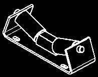
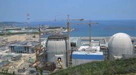
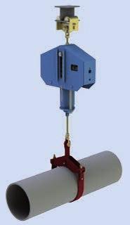
34 Field of application To avoid unacceptable forces and moments in pipe systems, the thermal expansion of the piping must not be restricted. Constant hangers s 11-14, Constant supports 16 Minor thermal displacement in the pipe systems in the vertical direction can be compensated by spring supports or spring hangers. Due to the resulting proportionally increasing force deviation corresponding to the spring rate, their use is limited to a displacement range specified by the designer (see product group 2, pp 2.5 and 2.6). In the case of greater vertical displacement the use of constant hangers or constant supports is required. For these special designs, the spring force is transformed into a constant force throughout the displacement range (see function principle, page 1.5). The proportional loads of the pipe system can in this way be constantly distributed over the whole displacement range without significant deviations. s a rule, for LISG constant hangers the use of 11, tried and tested over 100,000 times, provides the standard solution. Constant hanger 11 The function principle is based on the arrangement of three springs resulting in the parallelogram of forces. The design is distinguished by highly functional accuracy along with wide load adjustment ranges. The favorable performance-to-weight ratios and symmetrical designs enable easy installation. For further typical advantages, see page 1.3. Constant hanger in a coal-fired power station Final assembly of a constant hanger Installation inspection of a constant hanger 1.1


35 Constant hangers 18 s a rule, the pipe support engineer allows for sufficient installation space for the supports required. However, due to limitations of space the installation height can be too small for the typical standard solution with 11. This sometimes occurs, especially when reconstruction existing plants. To provide the optimum solution in such cases, 18, a low profile design, is available from the LISG hanger range, besides the main 11 series. The function principle of this design is based on the lever principle. Unlike the usual leverarm hangers, the load displacement here is linear and is constant, following the LISG principle (see function principle, page 1.6). In the case of constant hangers, the pipe systems are suspended from roof constructions or the steelwork. If the piping is laid out near ground level it may be appropriate to take up the loads from below with constant supports. Constant supports 19 Due to its compact design, constant support 19 thereby replaces its predecessor, 16, as standard. Type 16 continues to be standard only in the heavy-duty range (load range kN) for its coupling capacity. Constant hanger 18 On the basis of their special function principles and modes of design, LISG constant hangers and supports have, for the past five decades, proven their outstanding operational safety and reliability many thousands of times. Further descriptions of their mode of operation and function are set out on page 1.6 and their design features from page 1.7. Constant support 19 1 For the operational safety and long life of the pipe systems and hence of the plant itself, the consistent functional accuracy of the constant hangers is of utmost importance. In comparison with conventional lever-arm hangers the new LISG 18 is lower profile and enables the creation of support chains in the smallest of spaces. Space-saving design of 18 compared to a conventional lever-arm hanger 1.2

36 Special benefits of LISG constant hangers and supports a b f g h i The user can profit from a variety of special benefits where LISG constant hangers are concerned. Significant savings are possible, especially regarding labor-intensive ancillary support costs such as planning, installation and operation. c d e Constant hanger 11 c a b e Constant hanger 18 c a b Constant support 19 axis of symmetry j f g h j i g h j i a Principle-based constancy by way of a special function principle. b Pre-relaxed springs eliminate any significant loss of load-bearing capacity. c Reduced friction due to minimized number of bearing points. d specially wide load adjustment range avoids hanger replacement when operational loads change. e Turnbuckle and swivel joint function allows greater adjustment of pipe installation position. f Load application free of moments due to a single suspension point. g locking device through fine rasterization nearly infinitely variable. h Name plate contains complete technical specifications. i Directly readable travel scale with marking for hot/cold positions. j Load scale with permanent marking of set load. 3 Symmetrical design ensures direct flow of forces through axis of symmetry. 3 Favorable performance-weight ratios for reduced installation loads. 3 rranged by load groups and travel ranges to simplify selection (modular system). 3 Consistent functional behavior due to highquality corrosion protection and maintenance-free chemically nickelized finishes. 3 Readily adaptable to installation situation via corresponding designs and standardized accessories. 3 Double load-tube guiding of constant supports for transmission of side loads. 3 Secure connection of load chains due to load- and connection-compatible modular components. 1.3


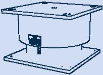
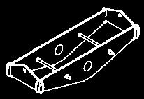
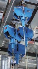
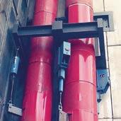
37 LISG constant hanger and support s 1 s fixed elements in the pipe system concept, the pipe supports must operate smoothly as functional connections between the pipe system and the surrounding structure. Type 11 Pipe systems are usually very complex layouts with restricted space. To allow for optimum use of the different spatial conditions, various designs are available as standard for the different application situations. ll components are available either from stock or at short notice. Constant hanger 11 C3 19 to Standard design for use as suspension for loads up to load group 9 (100kN) and travel range 6 (750mm). Travel range 7 (900mm) is available on request. If no space restrictions or other specifications are to be considered, this is the preferred product. Constant hanger 11 with support brackets 71 C3.1 to Standard design with support brackets bolted at the LISG factory for use as seated versions. Type 11 with support brackets Constant hanger 18 D3 17 to Serial standard design in special low profile version as alternative suspension to 11, if the installation height is limited. Constant support 19 D3 17 to Serial standard design for use as support if constant support from below is required. Type 18 Note: This version replaces the taller single-cell constant hanger 16 (see Standard Supports Catalog 2010) and is especially suitable in restricted spaces. Type 16 can still be supplied if required. Heavy constant support 16 Special design as multi-cell constant support 16, if heavy loads have to be distributed. Type 19 Servohanger to Servohangers are equipped with additional active load regulation and can reduce overloading in the piping system to a permissible harmless level. Type 17 with support brackets Type
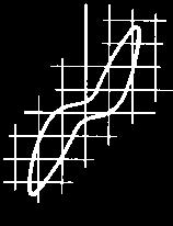
38 WIRKUNGSWIS UND FUNKTION F 2 F2 D C D C F F C D F1 F Mode of operation and function Types 11, 12, 13, 14, 16, 79 Obere Stellung Upper position Middle Mittlere position Stellung esondere nforderungen n die zuverlässige Funktion von Konstanthängern sind strenge nforderungen zu The LISG Function Principle stellen: The LISG Function Principle is based on the exakte Konstantheit interaction bei jeder of the force from a mainspring and Lasteinstellungthe resulting force of two connected balance minimierte mechanische springs. The Reibungskräfte force directions of the pre-loaded compensating springs are thereby angled benso sind für die against laufende each Überwachung other in the shape of a parallelogram of besondere forces. Vor- des Rohrleitungsverhaltens aussetzungen zu erfüllen: zuverlässige Kontrollanzeigen The suspended für load F acts directly on the instelllast und mainspring Wegstellung via the load tube. The preloaded compensating springs C act additionally ausreichende und präzise on the load tube as the resulting force F2 Nachstellmöglichkeit der Last via pivoting cams D and roller supports. The mainspring force F1 and the resulting force Das LISG-Funktionsprinzip F2 change on the shifting of the load over the Für die rfüllung der nforderungen bietet das patentierte LISG-Funktionsprinzip displacement range die in accordance with the besten Voraussetzungen. specified Hiernach spring beruht constants, the cam path, and die Wirkungsweise the auf angular dem Zusammenwirken der Kraft aus einer Hauptfeder und der position of the cam components. resultierenden Kraft The zweier course zugeschalteter of the resulting force corresponds usgleichsfedern. Die Kraftrichtungen der vorgespannten usgleichsfedern to the characteristics sind dabeiof the mainspring. In this nach rt eines Kräfteparallelogramms way the mainspring winklig force is balanced out, gegeneinander gerichtet. without deviations, to a constant support force. F2 D C F1 F G Funktionsweise der LISG-Konstanthänger Lower position Untere Stellung = = = =75 F Die anhängende Last F wirkt über das The LISG function principle leads to Lastrohr direkt auf die Hauptfeder. Die Vorspannkräfte der absolute usgleichsfedern constancy C which by theory can wirken als resultierende easily Kraft F2 be über proven. schwenkbare Kurventeile D und die Stützrollen zusätzlich auf das Lastrohr. The LISG Die Hauptfederkraft F 1 und die Resultierende F2 verändern function principle permits an especially wide load adjustment range of sich bei Verschiebung der Last über den ewegungsbereich s entsprechend 40% 100% den of vorgegebenen Federkonstanten, der Kurvenbahn the nominal load. und der Winkelstellung der Kurventeile. Der Verlauf der Resultierenden entspricht exakt der Kennlinie der Hauptfeder. Dadurch wird die Kraft der Hauptfeder ohne bweichungen zu einer konstanten Stützkraft ausgeglichen. Load adjustment The load adjustment is carried out by a preloading of the mainspring. s the characteristics of the resulting balancing force and the mainspring are the same, only a linear shifting of the initial force thereby occurs F1. This way, the change in force is the same at every point of the movement and the ultimate load remains constant at each load setting. djustment bolts The remaining travel range changes proportionally to the load alterations. 1.5


39 Mode of operation and function Types 18, 19 1 C D F C D F D C F Function principle for LISG constant hangers 18 and constant supports 19 The function principle is based on the lever principle, by which variable spring forces are transformed into a constant support force by way of lever mechanics. Two lever arms, symmetrically arranged at an angle to each other, thereby act as one system with pre-loaded springs. On a vertical change in position of the load F to be taken up, the displacement is distributed over rollers C and defined bearing surfaces onto the lever systems. Through the pairing arrangement of the levers the displacement runs linearly in the axis of symmetry, whereby the lever conditions that thereby change do so proportionally to the correspondingly changing spring preloading. In this way the load stays in balance with the set set load in every travel position. Sinus-shaped load deviations from the lever movement in the form of an arc are balanced by correspondingly machined cam profiles. This way the load distribution is held constant with mathematical accuracy in every position. Load adjustment The set load is adjustable within a range of approx. 50% to 100% of the maximum hanger force. y way of an adjusting hex-head bolt D the length of the lever arm force is continuously variable. On all load settings the available travel range remains unchanged. The whole working travel range is always available. Spring force Lever arm Leverage Load arm Load 1.6

 has a defined thread engagement depth and the lower one is")


40 Design features LISG constant hanger 11 standard design LISG constant hanger 18 compact design 79 trapeze 71 support bracket 11 constant hanger Design Structure steel body encases the moving parts such as springs and cam lever. The compact arrangement of the individual components enables small external dimensions. The body is designed to bear loads and is mass-produced for the attachment of standardized connections. Connection possibilities The connection threads correspond to the respective LISG load group, whereby the upper connection thread ( 11) has a defined thread engagement depth and the lower one is designed as a adjusting nut for length compensation. Due to their design, 11 constant hangers can also be seated directly on suitable supporting components without the need for access ories. In addition, special support brackets can be bolted on using the standard tapped holes provided. Type 11 constant hangers above load group 9 (heavy duty) and 18 constant hangers are fitted with yoke plates (only on top) for a pined connection, instead of connection threads. Serial connection s 66 tie rod 61 threaded clevis with pin 60 eye nut 67 stud bolt Performance range Constant hangers and supports are produced as standardized single-cell hangers in load groups C to 9. In addition, 11 constant hangers in sizes 8 and 9 are coupled to form hangers for higher loads (heavy duty). In this way a standard performance range from 0.13kN to 500kN is covered. Constant hangers are manufactured in the seven standard travel ranges 75 / 150 / 300 / 450 / 600 / 750 / 900 mm and constant supports up to 300mm. Standards and calculations Component design and layout correspond to the applicable national and international standards and recognized technical specifications with regard to load capacity, function and lifespan. This applies equally to the materials used, the welding technology and other processes. The relevant details are clearly defined in the technical specifications, page 0.9. Springs The springs are crucial components for the smooth functioning of constant hangers and supports their long-term functional efficiency is vital for the operational safety of hangers and supports. The relevant standards are the basis for the design of LISG helical coil springs. Details can be found in the technical specifications, section 0. Spring relaxation When subjected to loads and temperature over a period of time, conventional helical coil springs lose part of their reset force through relaxation (settling loss). In constant and spring hangers this can, in the long term, lead to a reduction in the set ultimate load of more than 10% (see calculation example). LISG exclusively uses springs that, through an artificial aging process, show no appreciable settling loss. The spring relaxation normally to be expected is anticipated by producing preplastification in a hot setting process with greater coil lengths. steelwork provided by customer 1.7

 0.0-1.0-5.1-6.9 0.3 0.0-4.4-20.7-30.4-36.4-19.2-1.0 0.0 The maximum primary stresses were calculated in the vicinity of the boiler connection.")

.")
41 boiler outlet header boiler 1 Calculation example of cumulative additional loads due to hanger relaxation pipe system was observed (dia = 525mm, s = 27mm, temperature = 540 C, pressure = 50 bar). The effect of a 10% loss of force in the hangers was assumed. Due to this loss, the pipe system is displaced by 36.4mm. connection point / hanger planned condition set load of hanger hanger load condition after 10% relaxation additional z-load at connection points (in kn) z- displacement of pipe system (in mm) The maximum primary stresses were calculated in the vicinity of the boiler connection. They stand 93% above the planned stress condition. The permissible stresses for the boiler connection are exceeded by 9% (calculations according to Regulation 31.1). Corrosion protection The constant hangers are finished with a LISG standard coating which, together with a metallically pure treated surface, offers superior corrosion protection with high mechanical stability. earings and bearing bolts for the constant hangers are plated or made of nonrusting materials. ll threaded components and cams are electro galvanized. The surface of the spring is given a special finish (technical specifications, page 0.11). Constant hangers with standard corrosion protection need no maintenance if installed in buildings or in locations protected from the weather. For operation in the open or in special situations, corresponding extra corrosion protection can be arranged see the corrosion protection section in technical specifications, page Paintshop Spring testing at material reception 1.8


, max. W 6% in relation to the operating load VG-R510L and KT 3205.3, Germany, max.")
42 Function testing Functional performance The special functional principle of LISG constant hangers guarantees constancy across the entire travel range. This is also unaffected by shifts in load. Only a minor adjustment force produced by tolerances and bearing friction is to be taken into account. The hysteresis so produced is kept within strict limits due to the design principle and modern production processes. In effect, the deviation in the set load of LISG constant hangers on the serial average can, on normal load setting, be kept to w 3%. pplying a selection process, with limited load and travel ranges, it is possible to reduce this even further. The typical permissible deviations are set out in the following international codes: MSS SP-58 (US), max. W 6% in relation to the operating load VG-R510L and KT , Germany, max. W 5% in relation to the operating load. The deviation in load adjustment (medium load) is limited to W 2% DIN N T3 max. W 5% in relation to the operating load Function testing efore shipment, all constant hangers and supports are tested for flawless functioning and set to the load ordered. The test results are recorded. The calibration values are stamped onto a riveted name plate. The adjusted load is also marked permanently on the load scale. Hot and cold positions are noted on the travel scale in red and white respectively. The respective travel positions can be read directly off the travel scale in mm or inches. cceptance testing of a constant hanger Calibration, testing and blocking of a constant hanger 12 on a 500kN test bench The set load in each case can be read directly off a load scale in kn or lbs. For the functional tests, test benches operating quasi-statically with capacities up to 1,000 kn are on hand. The test benches are checked regularly by an independent supervisory body. 1.9


43 1 LISG testing technology is constantly under improvement and represents state-of-the-art technology. These improvements cover test benches for constant hangers and supports, spring hangers and supports, as well as snubbers. The testing facilities are in operation at all production sites within the LISG group, while mobile units are available for use at customer locations. 32 test benches are on hand for constant and spring hangers or constant and spring supports in the load range from 1kN to 1000kN. ll LISG test benches are tested at regular intervals according to DIN N ISO 7500 with calibrated load cells and measurement amplifiers. ll components are tested in installation condition and adjustment. xample of a test certificate in a standard delivery inspection Testing a constant hanger on a LISG 120kN test bench Mobile LISG 50kN snubber test bench PR50 Testing a spring hanger on a LISG 120kN test bench 1.10
44 Installation overview Universal adaption to existing installation spaces The installation of the constant hangers can be adapted to any situation in the plant through the use of universal accessory components from the modular system. utomatic designing ll configurations can be created in just a few steps via the LICD design software in the shortest of time with the input of 6 parameters with parts lists and drawings


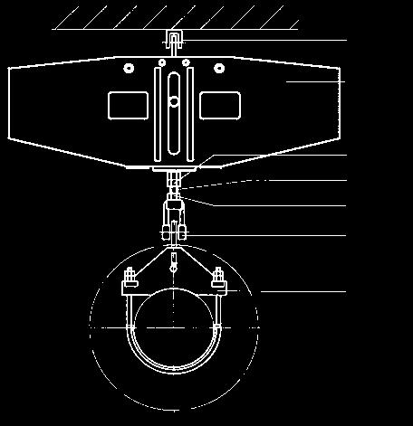
45
46 Selection overview Types 11, 12, 13, 14, 16, 79 f Constant hangers, heavy duty constant supports a travel range [mm] ,625 1,25 2, load [kn] Selection example: 24kN/210mm Zwischenwerte Intermediate können values can interpoliert interpolated. werden be...2..(150mm) d...3..(300mm) d...4..(450mm) d...5..(600mm) d...6..(750mm) d designation C3 11 D D b 0.25 b e 12 82e 12 93e 12 92e 13 83e 13 82e e 13 92e e 14 82e e 14 92e load [kn]
47 a For the selection of constant supports and angulating constant supports 16, the load group and travel range of the corresponding constant hangers 11 apply. b Loads l 0.25kN or 0.13kN on request. c This range is only adjustable ex works. d Total travel, travel range 7 (900mm) supplied on request. e Selection also applies to heavy duty constant support 16. f ased on travel range [mm] load [kn] load [kn] c c D e e e e e e 11 C3 11 D e e e e e e designation mmd mmd mmd mmd mmd 1.14


48 Constant hangers Type 11 Constant hangers 11 C3 19 to Serialized standard design, delivery from stock. H P O Ø d 2 Ø d 2 X b b a X D d 6 d 5 R Q C L a Dimension for uppermost blocking position, in other blocking positions lengthens accordingly. b X = minimum thread engagement depth. t the lower connection, maximum thread engagement depth = X + 300mm. Order details: constant hanger marking: set load: kn travel: mm up/down blocking position (as required): mm 1.15 C D d 2 d 5 d 6 a H L O P Q R X weight b 11 C M10 9 Ø D M10 11 Ø D M10 11 Ø M12 12 M M12 12 M M12 12 M M12 12 M M12 12 M M12 12 M M12 12 M M12 12 M M16 12 M M16 12 M M16 12 M M16 12 M M20 16 M M20 16 M M20 16 M M20 16 M M24 20 M M24 20 M M24 20 M M24 20 M M30 25 M M30 25 M M30 25 M M30 25 M M30 25 M M36 35 M M36 35 M M36 35 M M36 35 M M36 35 M M42 35 M M42 35 M M42 35 M M42 35 M M42 35 M M48 35 M M48 35 M M48 35 M M48 35 M M48 35 M


49 G1 Support brackets Type 71 for constant hangers Type 11 K1 Z T F c y C L 1 transportation lug b U 1 detail Z base plate d 1 Support brackets for constant hangers C3.1 to Serialized standard design, delivery from stock. Material: base plates of brackets: plate t 15mm : S235R plate t 20mm : S3552 constant h. bracket a 1 1 C b F G 1 K 1 L T U y d 11 C C D D D D weight a The 5 th digit in the designation denotes the design: 6 for support brackets, bolted, standard design, 8 for support brackets, bolted, for increased requirements. b Dimension for uppermost blocking position, in other positions changes accordingly. c The constant hangers can in principle be directly seated and welded to the structure. Care must be taken to allow access to adjusting bolts and adjusting nut. If this is not possible, supports 71 are appropriate. d Minimum weld seam. Longer support brackets are available on request. Order details: constant hanger with support bracket marking:... set load: kn travel: mm up/down blocking position (as required): mm 1.16


50 Constant hangers Types Constant hangers to Standard design, multi-cell arrangement, delivery from stock. O W S R R1max D d 3 a H P L C S R W R 1max N M d 3 a Dimension for uppermost blocking position, in other blocking positions changes accordingly. Order details: constant hanger marking:... set load: kn travel: mm up/down blocking position (as required): mm C D d 3 a H L M N O P R R 1max S W weight x x x x x x x x x x x x x x x x x x x x


51 Constant hangers Type with support brackets 1 a detail Z transportation lug a U b Constant hangers with support brackets to Standard design, delivery from stock. Material: base plates of brackets: plate t 15mm : S235R plate t 20mm : S C a F G 1 G 2 a K 1 N T U Z b weight a Dimensions and G 2 for uppermost blocking position, in other blocking positions and G 2 changes accordingly. b Minimum weld seam. Other lengths are also available on request. Order details: constant hanger with support brackets marking:... set load: kn travel: mm up/down blocking position (as required): mm 1.18
52 Constant hangers Type 18 Constant hangers 18 D3 17 to Standard design, delivery from stock. s d 3 R H W a d 2 X b a Dimension for uppermost blocking position, in other blocking positions lengthens accordingly. b X = minimum thread engagement depth. t lower connection max. thread engagement depth = X + 150mm. Max. permissible loads: mergency (C) at 80 C = set load x 1.33 Faulted condition (D) at 150 C = set load x 1.66 Max. load in a blocked state at 80 C = set load x 1.5. Order details: constant hanger marking:... set load: kn travel: mm up/down blocking position (as required): mm min. load [kn] max. load weight [kn] travel d 2 d 3 a H R s W X b 18 D M D M D M D M M M M M M M M M M M M M M M M M M M M M M M M M M M M M M M M M M M M M M M M M M M M M M
![a Constant supports Type 19 1 Constant supports 19 D3 17 to 19 93 17 Standard design, delivery from stock. c H ØL 1 K M 1 d 4 N 1 b min. load [kn] Order details: max.](/docs-images/93/114255555/images/53-2.jpg "load [kn] travel 1 1 d 4 a H K c M N 19 D3 17 0.21 0.51 300 973 245 205 163 14.5 913 430 80 185 103 59 19 D1 27 0.21 0.72 75 610 245 205 163 14.5 490 234 80 185 103 37 19 D2 27 0.21 0.72 150 664 245 205 163 14.")

53 a Constant supports Type 19 1 Constant supports 19 D3 17 to Standard design, delivery from stock. c H ØL 1 K M 1 d 4 N 1 b min. load [kn] Order details: max. load [kn] travel 1 1 d 4 a H K c M N 19 D D D D The sliding surface of the mating component should be fitted with stainless steel plating. This is indicated by the suffix SP in the designation (e.g., clamp base SP). constant support , marking:, set load: kn, travel: mm up/down, blocking position (as required): mm weight Load plate with integrated slide plate. This must be considered in the selection of clamp bases. a Dimension for uppermost blocking position, in other blocking positions shortens accordingly and allows adjustment of + 60mm. b Type is fitted with a load plate with PTF slide plate as standard. If needed, this can also be supplied with a high temperature slide plate, (see table below). c Under certain circumstances the support bracket with the height K can be dispensed with. It should however be ensured that the load adjustment bolts are accessible. 19* with slide plate up to 180 C up to 350 C ØL 1 19 D D * friction value of the slide plates see table on page 7.11 Max. permissible loads: mergency (C) at 80 C = set load x 1.33 Faulted condition (D) at 150 C = set load x Max. load in a blocked state at 80 C = set load x


 at 150 C = set load x 1.66. Max. load in a blocked state at 80 C = set load x 1.5. Order details: angulating constant support 19.")
54 ngulating constant supports Type 19 ngulating constant supports 19 D3 37 to Standard design, delivery from stock. SW For large horizontal displacements in the pipe systems the constant supports can be fitted with ball bushing joints. U b d 3 1 H 1 The ball bushing joints for the connection are designed to fit weld-on bracket 35. a Dimension for uppermost blocking position, in other blocking positions shortens accordingly and allows adjustment of +200mm. b Connection possibilities: See bolt diameter of weld-on brackets 35 or dynamic clamps (product group 3). Max. permissible loads: mergency (C) at 80 C = set load x 1.33 Faulted condition (D) at 150 C = set load x Max. load in a blocked state at 80 C = set load x 1.5. Order details: angulating constant support marking: set load: kn travel: mm up/down blocking position (as required): mm min. load [kn] max. load [kn] travel 1 1 d 3 b a H SW U 19 D D D D weight 1.21
![Constant hanger trapezes Type 79 1 L R Ø d 3 s b a U 1 d min. load [kn] d max. load [kn] travel L max d 3 a R s U 1 weight for c L=1000 w per 100mm 79 D3 17 0.42 1.](/docs-images/93/114255555/images/55-0.jpg "02 300 1700 973 205 17 569 25 10 80 140 119 1.7 79 D1 27 0.42 1.44 75 1700 610 205 17 372 25 10 80 140 81 1.7 79 D2 27 0.42 1.44 150 1700 664 205 17 409 25 10 80 140 89 1.7 79 D3 27 0.74 1.")


55 Constant hanger trapezes Type 79 1 L R Ø d 3 s b a U 1 d min. load [kn] d max. load [kn] travel L max d 3 a R s U 1 weight for c L=1000 w per 100mm 79 D D D D b b b b b b Constant hanger trapezes 79 D3 17 to a Dimension for uppermost blocking position, for other blocking positions lengthens accordingly. b The L max dimensions can be lengthened to 2400mm, on reduction of the permissible center load by 5% per 100mm extension. c When selecting the constant hanger trapeze the weight of the channels and the clamp base weight must be added to the operating load. d Max. permissible loads: mergency (C) at 80 C = set load x 1.33 Faulted condition (D) at 150 C = set load x Max. load in a blocked state at 80 C = set load x 1.5. Order details: trapeze L = mm marking: set load: kn of the support point trave: mm up/down blocking position (as required): mm 1.22


: mm max C c D c G e L max X a total weight L=1000 d weight change [kg/m] d 79 D2 15")
56 Constant hanger trapezes Type 79 Constant hanger trapezes s 79 D2 15 to This design of trapeze is used if the standard design does not fit due to extremely restricted installation space. The trapezes are supplied bolted ex works. b Z L G D c a X c C a X = min. thread engagement depth + 300mm engagement possibility. b Dimension L and dimension Z are to be stated when ordering. c Dimension and dimension C at blocking position 0 mm, in other blocking positions and C lengthens accordingly. d When selecting the constant hanger trapeze its total weight and the clamp base weight must be added to the operating load. e The L max dimensions can be lengthened to 2400mm on load reduction by 5% per 100mm extension. Order details: trapeze L = mm Z = mm marking: set load: kn of the support point travel: mm up/down blocking position (as required): mm max C c D c G e L max X a total weight L=1000 d weight change [kg/m] d 79 D D


57 Heavy duty constant supports Type 16 1 Heavy duty constant support s to c 1 1 C D a b F H K L M N O P S T Z weight a Dimension for uppermost blocking position, in other blocking positions shortens accordingly and allows adjustment of + 60mm. b Dimension for constant supports according to a, which are additionally fitted with a slide plate. c Type is supplied as standard with a corrosion protected load plate without a slide plate. If lateral movement occurs the use of sliding plates are recommended. Please note the table on the right. When using slide plates the sliding surfaces of the mating components should be fitted with stainless steel plating. This is indicated by the suffix SP in the designation (e.g., clamp base SP). Ø L 1 Load plate with integrated slide plate b 16 with slide plate* up to 180 C up to 350 C ØL * Friction value of the slide plates see table on page Order details: constant support marking: set load: kn travel: mm up/down blocking position (as required): mm 1.24


58 Servohangers Type 17 Under certain conditions, pipe systems or other components are restricted in their thermal displacement through friction or other influences, despite the use of spring and constant hangers or constant supports. In such cases servohangers can actively overcome the restriction. pplication In standard cases, the weight of the pipe systems is practically in equilibrium with the set load of the constant hangers and constant supports. The sum of the deviations occurring and the additional stresses in the piping due to this then remain within the permissible harmless range. In certain cases, the sum of the deviations occurring can also exceed a permissible level and considerably reduce the life of the piping systems or their connections (in the creep strength range) in the form of additional secondary stresses. Deviations can arise through: wall thickness tolerances of the piping, if these are not weighed extra and the weight differences taken into account insulation weights not determinable in advance mechanical friction and production tolerances for constant hangers (permissible +/ 5%) spring relaxation pipe statics that are not always readily determinable practical deviations from the theoretically planned load distribution combination of deviations can cumulatively reach significant levels. These deviations have a particularly negative effect in flexible, soft pipe systems. Vertical expansion can be obstructed or even completely suppressed here, even with relatively slight individual deviations. part from the additional loads caused, impermissible sagging can result, due to spring hyste resis in the pressure-stressed system, with a reversed incline. In addition to possible creep rupture, in the event of an incorrectly positioned incline, dangerous water hammer can occur. In such cases it would be advisable to supplement the passively reacting constant hangers with the active LISG servohangers. Typical cases of application for LISG servohangers: boiler center boiler center turbine turbine original cold position hot position new cold position without servohangers (diagram on left) the pipe system remains in the hot position with servohangers (diagram on right) the pipe system shifts to its specified positions 1.25
. For theoretical (temp.")


59 Through use of the hydraulic servo support the pipe system can now be repositioned to the specified elevation. Design and mode of operation The 11 constant hanger forms the basis for the servohanger. To overcome load differences it is additionally fitted with an auxiliary hydraulic device that can exert an active supplementary force in both directions (servo support). For theoretical (temp.) / actual (travel) deviations a tolerance range can be set. If the deviation is outside these values, the control switches off automatically. Manual switch-off For any maintenance work required on the system or the boiler, the servo support can be switched on or off manually. Design sizes Load Groups 5 (F N 20kN) to 9 (F N 100kN) with travel ranges 2 (150mm) and 3 (300mm) are considered standard. For other cases, special designs can be supplied. Operating instructions Installation and commissioning instructions, as well as servicing recommendations, are included in the scope of supply. Servohanger switch cabinet 1 a For this, see also selection table constant hangers, pages 1.13 and b 2 = travel range 2 3 = travel range 3 In standard cases, the temperature of the pipe system to be supported is used as a control parameter. The temperature in each case is transformed electronically into the corresponding travel position. In the theoretical / actual comparison procedure, the control ensures a regulated approach to the actual vertical elevation position. servohanger b nominal load F N [kn] set load a [kn] load-dependent travel a travel range 2 travel range 3 [mm] [mm] additional servo force [kn] W W W W W 20 lectro hydraulic control The hydraulic unit and the control are located separately from each other in a separate switch cabinet situated near the servohanger (max. distance 16m). hydr. control electr. control theoretical actual The hydraulic pistons for control of the movement are located in the load tube of the constant hanger. Safety switch The electro hydraulic control is designed so that in the event of an operational breakdown (e.g. power loss) only the servo support is lost, but the unit will continue to function effectively as a constant hanger. Function chart 1.26
 f travel scale g blocking strip h indicator for set load i load scale j load adjustment hood k load adjustment")
 1 Transport and storage During transport, care must be taken that connecting threads, blocking")


60 Installation and operating instructions Types 11, 12-14, 18, 19 a blocking device b guide pin c name plate d red marking for hot position e retaining bolt with washer for blocking device (after deblocking) f travel scale g blocking strip h indicator for set load i load scale j load adjustment hood k load adjustment bolt l load tube m inspection hole for min. thread engagement depth n adjusting nut (with swivel joint) 1 Transport and storage During transport, care must be taken that connecting threads, blocking devices and load adjustment bolts are not damaged. When storing in the open air, the supports must be protected from dirt and water. 2 Delivery condition If not otherwise agreed, LISG constant hangers are set to the desired cold load position b e f k m a c d g h i j l n (installation condition) and blocked. The adjustment values can be read off the load and travel scale as well as the name plate. On the travel scale the theoretical hot position is marked with a red sticker and the theoretical cold position with a white one. t the delivery inspection the customer specified load set at the factory is permanently marked on the load scale with an X. The reading is made at the level of the guide pin center. a e hi g Low profile constant hanger 18 b c d f n adjustment spindle l Constant hanger 11 a e hi g b c d f Travel scale with cold/hot marking a e g k b c f h i j Constant support 19 support brackets ball bushing joint adjustment spindle l n l a hi g b c d f Coupled constant hanger ngulating constant support 19 ball bushing joint Load scale with indicator 1.27
 serial number LISG order number calibration load (set load) inspector travel ident.")

 The upper connection is designed as a yoke plate.")
61 79 trapeze 71 support brackets 11 constant hanger 66 tie rod 61 threaded clevis with pin 60 eye nut 67 stud bolt 1 X Name plate with stamped operating data Stamped on the plate are: Min. thread engagement depth X of upper connection (see selection table 11, page 1.15) serial number LISG order number calibration load (set load) inspector travel ident. number steel construction onsite (bolted or welded) l Connections 11 C (single cell hangers) The upper connection is designed as an inner thread with limited engagement depth. The lower connection is designed as a spherical adjusting nut pivotable in all directions by min. 4. The connection threads are greased and sealed with plastic caps. When connecting to the connecting rods, care must be taken that the lower rod is screwed into the adjusting nut at least to the inspection hole. further thread engagement depth of at least 300mm is available. Connections (heavy duty) The upper connection is designed as a yoke plate. The lower connection is also designed as a yoke plate and fastened to the spherical adjusting nuts of the individual constant hanger cells, whereby pivoting of min. 4 is possible. Constant hangers 11 (seated) These constant hangers for all load sizes can be directly seated. They can also be supplied with serial support brackets 71 which, depending on the order specifications, can be connected and bolted via precision-fit boreholes at works or on site. The base plates of the support brackets can be welded to the contact surface. On request, support brackets with slot holes for bolting can be supplied. Connections 18 The upper connection is designed as a yoke plate and the lower one as a spherical adjusting nut, pivotable in all directions by min. 4. The connection threads are greased and sealed with plastic caps. Connections 19 The upper connections of the constant supports are fitted either with a load plate or slide plate to reduce friction from lateral displacement, or with a ball-joint lug for angulating constant supports. The lower connections are therefore either a pedestal or a lug. During welding work at the pedestal the components inside constant supports must be protected. Inspection hole Min. thread engagement depth of connection rod in load tube 1.28
62 Transport lock (heavy duty) Coupled constant hangers are supplied with a transport locking device (marked in red) consisting of a retaining rod, washer and retaining nut. ) The connecting rods are to be installed vertically for the purpose of better inspection. con trolled angled position in operating condition is thereby permitted. In all events, uniform specifications for the whole installation should exist. cold position hot position The connecting rods and points are to be coupled force-locked. Type 11 C (single cell hanger) For installation of the constant hangers, transport lugs or other assembly devices can be screwed into the threaded holes on the sides. fter deblocking of the hanger (see point 4) the blocking devices are to be screwed on here for safe keeping. For constant hangers with support brackets 71 the hangers are fitted with transport lugs instead of the upper connection these can also store the blocking devices. Rods vertical during plant operation 1.29 hot position cold position Rods vertical in installation condition Transport lock retaining rod 2 washer 3 retaining nut The transport lock is loosened only on completion of hanger installation and at the same time as the removal of the blocking devices. For this, the retaining nut with washer marked in red are removed at the lower end with a socket wrench. oth parts are to be stored in the same place as the blocking devices. When making the force-fit connection, care must be taken that the lower threaded rods are screwed into the adjusting nuts at least up to the inspection hole. The installation dimension of the lower yoke plate can be lengthened with the adjusting nuts by 250mm or shortened by 70mm. 3 Installation of the constant hangers When installing, the specifications of the installation instructions for pipe systems must be followed. Special attention must thereby be paid to the desired installation position of the suspension rods throughout the whole support chain. There are two possibilities here: ) The connecting rods are to be installed at an angle according to the expected horizontal displacement in the pipe system. perpendicular position is hereby anticipated in operating condition. Constant hangers s For installation of the hangers, the side openings of the upper yoke plate can be used for hooking on. For hangers with support brackets, the upper yoke plate is replaced by a transport lug. 4 Deblocking Requirements The correct deblocking of the constant hangers in accordance with the following instructions is crucial for the subsequent faultless functioning of the pipe systems. s far as possible, the blocking devices are to be removed, immediately / shortly before commissioning. The blocking devices must be removed as a matter of principle in a systematic way, one after the other, beginning at a fixed point or connection point. The whole system should be inspected beforehand according to point 3 of these installation instructions. ctual and theoretical condition When it has been ensured that all connections are firmly force-locked, the suspended weight is completely taken up by the constant hangers or supports.

63 If the weight load corresponds to the set load and the piping system shows no sign of stress, then the planned equilibrium has been achieved. The blocking devices can be easily removed. In practice however, slight stresses in the piping systems and hence resulting load shifting can hardly be avoided. In the same way, the loads, which are usually determined theoretically, can show larger tolerances. s a result, the deviations can lead (according to under- or over-load) to corresponding jamming of the guide pin in the lower or upper section of the blocking device. Procedure The blocking devices can only be removed when the guide pin is centered in them. The set load is made up of the cold load and the extra weight of the hanger components suspended. If the guide pin is lying at the top or the bottom, the load adjustment must be adapted before deblocking (see point 5, load correction): When removing the blocking devices, care must be taken that only the outer locking ring is loosened. In cases of requirement, e.g. for revisions, the hangers or supports can be blocked again in any position. For this, the blocking devices are placed on the guide pin and secured. The blocking devices should be firmly bolted to the side of the constant hanger body in s 11 to 14, when they are not in use. Load distribution Under no circumstances should the blocking devices be removed by force! y loosening or tightening the connecting rods with a few turns of the adjusting nut in the case of constant hangers, or corresponding adjust ment of the support tube for constant supports, stresses in the pipe system can be compensated for and the guide pin is then free. The geometrical position of the pipe system must not be altered when balancing stresses! s later adjustment at one point can cause a renewed slight shift at another, the procedure must be repeated if necessary at different points. For clear control it is recommended that, as a matter of principle, the blocking devices should only be removed when all the guide pins are centered in them. 5 Load correction 11, Load correction is necessary if the set load (set at the LISG facility) deviates from the weight actually applied. In this case, with LISG hangers the set load can also be adjusted in the installed condition. 1 a) Guide pin is free: Set load of the constant hangers agrees with the weight applied. locking device can be removed. b) Guide pin lies at bottom: Set load of constant hanger is smaller than weight applied. Loosen connecting rod or increase set load. c) Guide pin lies on top: Set load of constant hanger is larger than weight applied. Tighten connecting rod or decrease set load. locked condition b ssembly of the outer locking ring a Dismantling of the outer locking ring and blocking device c Completed: deblocked condition It should thereby be taken into account that for load increases the remaining travel is shorter. In most cases this is not critical, due to the travel and load reserves available. For safety reasons this should be checked with the catalog data. ny changes in the installation dimension caused by load corrections must be compensated for within the load chain. Procedure: 1) Loosen both of the load adjustment locknuts. 1) 1.30


 Turn load adjustment bolts equally on both sides until the guide pin is free.")
64 2) 3) 2) lternate tightening or loosening the two load adjustment bolts, by a ¼ turn in each case. The base plate of the load adjustment hood and the lower edge of the constant hanger body must thereby remain parallel. The procedure is completed as soon as the guide pin no longer lies at the top or the bottom of the blocking device. If, for constant hangers of higher load groups, the necessary adjustment forces are too big and manual adjustment is not possible, auxiliary devices must be used (see point 6, auxiliary devices). 3) Tighten the locknuts of the load adjustment bolts. Now deblocking can continue. Load correction s 18, 19 y way of the load adjustment bolts j the length of the lever of the leverage arm is altered on the left and right respectively. On load adjustment the working travel remains unaltered. 6 uxiliary devices Tightening or loosening of the connecting rods, as well as load calibration, can be performed manually on all hangers. For hangers in the higher load groups this work can require a great deal of effort due to the higher load calibration. To facilitate the work, an auxiliary device can be made available with which a hydraulic load take-up using a handpump can be effected. It is operated by LISG personnel. Installation device, used to relieve the load adjustment bolts j j locking device bolted to front side Procedure: 1) Unlock tab washer. 2) Turn load adjustment bolts equally on both sides until the guide pin is free. 3) Secure load adjustment bolts against twisting by locking the tab washers. Installation device, used to relieve the adjusting nut 7 Inspection and maintenance The flawless functioning of the constant hangers and supports can be checked in every operating situation by examining the position of the guide pin. Under normal operating conditions, maintenance is not required. 1.31
65 Spring hangers, spring supports 2 spring Spring hangers, supports PRODUCT 2 GROUP

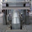
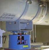
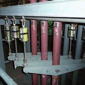
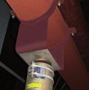

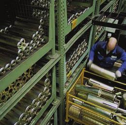
66
67 Spring hangers, spring supports Contents Page Field of application Special advantages of LISG spring hangers Overview of s spring hangers and spring supports Selection overview, spring components Selection tables Spring hangers Heavy duty spring hangers Spring hangers Heavy duty spring hangers Spring support Heavy duty spring supports ngulating spring supports Spring hanger trapezes Sway brace Telescoping spring supports Installation and operating instructions PRODUCT2 GROUP


68 Field of application To avoid constraining the system, thermal expansion in high-temperature piping must not be restricted. The piping must therefore be supported in a correspondingly elastic manner. Spring components To balance slight vertical displacement in the pipe systems, spring components are used as supports. These components function on the basis of preset helical coil springs which exert a variable supporting load over the range of movement in accordance with their specified spring characteristics. Load variations resulting from this are limited through the stress analysis calculations, depending on the sensitivity of the piping. The relevant basis for the function of the spring components are specified in the current guidelines (see technical specifications, page 0.5). LISG spring hangers and supports range of spring component designs are available for optimum adaptation to the various structural requirements. The ideal choice depends on the installation situation. Spring hangers and supports are as a rule calibrated in such a way that the spring force and pipe load are the same in the cold position (see page 0.5). The corresponding hot load position results from the theoretical pipe displacement (travel) and the spring rate. The difference in force between hot and cold positions acts on the pipe system as a reaction force and is governed by the relevant design specifications. Further information can be found on page 0.5. s standard practice, the permissible force deviation between cold position (blocking position) and hot position should not exceed 25 % in relation to the hot load. Moreover, as a rule constant hangers/supports are used that maintain a constant hanger/support force over the whole displacement range. Selection of spring hangers The reaction force depends on the spring rate (stiffness) of the respective coil springs. The change in force from cold to hot position results from the displacement. The greater the spring rate, the greater the change in load and accordingly the reaction force in the pipe system. For optimum selection of spring hangers and supports, LISG has divided the load ranges into 5 travel ranges. Details of their application can be found in the selection table (see pages 2.5 and 2.6), in the installation and operating instructions (page 2.19) and the technical specifications (page 0.3). Load setting and blocking Spring hangers and supports are checked for function and preset at the factory to the cold or blocking load and blocked in both directions of movement. This enables installation of the support in the designated installation space without time-consuming adjustments. In addition, the supplementary loads arising through pickling, flushing or pressure testing are held by the blocking devices. cold and hot positions are shown on the travel scale by white and red marking respectively the blocking devices have continuously variable settings and can be reused in any spring position 2.1

. 4 Fully adjustable blocking system. 5 On the spring hangers, the preset values are noted on the riveted name plate.")
69 2 Special advantages of LISG spring hangers axis of symmetry The user can profit from a wide range of special benefits with LISG spring hangers Significant savings are possible, particularly with regard to ancillary labor-intensive support costs such as planning, installation and operation Spring hanger Spring hanger 22 axis of symmetry 1 No welding (s 20, 21, 27). 2 Fully electro galvanized surfaces. For heavy duty designs: coated surfaces. 3 The cold or blocking position is marked on the travel scale (white arrow). 4 Fully adjustable blocking system. 5 On the spring hangers, the preset values are noted on the riveted name plate. 6 Special prerelaxed springs with a CD (cathodic electrophoretic dip coating) finish prevent any significant loss in load capacity. 7 Integrated connecting elements. 8 Variable connection possibilities within the load group selected and the possibility of later adjustment for load setting. 9 The theoretical hot position (operating position) is marked on the travel scale (red arrow). Five travel ranges from 0 to 400mm, load group C to load group 9 Three travel ranges from 0 to 200mm, load group 10 to load group 50. Load application free of moments by coinsiding the load axis with the axis of symmetry. Favorable performance-to-weight-ratios for reduced assembly weights. Modular system simplifies selection (load groups and travel ranges). Flexible installation configurations using standardized components. Secure connection of load chains through the load and connection compatibility of system components. 2.2
70 Overview of s Spring hangers and spring supports kN Heavy duty design kN Spring hanger 21 Spring hanger 25 Spring hanger 21 This design is the most commonly used and is fitted with an upper connection for suspension. It is used where the surrounding structure offers a suitable connection point and sufficient installation space. The upper connections can be universally adapted to the existing conditions using standard components. Spring hanger 25 This version is used especially if the permissible deflection of a support chain when using 21 was exceeded or if, due to shortage of space, a 21 spring hanger cannot be installed. The connection is made by a rod fed through the hanger. Spring hanger 22 This design corresponds functionally to 21 and is available for higher loads up to 400kN. Spring hanger 26 This design corresponds functionally to the seated spring hanger 25 and is available for higher loads up to 400kN. Spring support 29 Spring support 29 If the surrounding conditions do not permit suspensions, this design offers a suitable alternative as a support. For larger horizontal displacements of the support load and of steel/steel slide plate contact, under certain circumstances the functioning of the support can be adversely affected by any lateral forces generated. It is recommended to avoid this risk by using LISG slide plates. In this case the mating components must have a stainless steel surface and if necessary be fitted with a twist restraint. Spring support 28 This design corresponds functionally to spring support 29 and is available for higher loads up to 400kN. Here too, LISG sliding components can be used as an option. ngulating spring support 20 In contrast to the 29 spring supports, lateral displacements can be absorbed practically free of friction forces by this design. This way, resulting forces in all planes, both in vertical as well as horizontal directions of movement, are almost completely eliminated. ngulating spring support The angulating spring supports act in compression. They are fitted on one side with an adjustable load tube and a rotating ball bushing joint and on the other with a fixed ball bushing joint. The joints provide the appropriate connection to the 35 weld-on brackets and the dynamic clamps in product group 3.
71 Sway braces 27 These special components act in compression and tension directions and are used to stabilize the position of pipe systems and other plant equipment. The connection components correspond with those in product group 3 (dynamic components). With the LISG sway braces 27 the following settings can be made: load pre-tensioning installation dimensions free stroke dd-on components Slide plate for spring supports 29/28 To reduce friction between the load plate and mating component (e.g. clamp base), PTF sliding materials (up to 180 C) or suitable material for higher temperatures (up to 350 C) are used. The mating component should in this case have a stainless steel sliding surface. The selection of slide plates can be found on page Spring support (telescopic) 2 Spring hanger trapezes 79 These commonly used components combine the advantages of the spring hanger with the easy-to-install, weld-free plug-in trapezes. For restricted spaces the spring hanger trapezes can be supplied as special welded designs. Installation extension for spring support 29 To bridge larger installation heights, adapted installation extensions can be ordered (see page 2.11). ase plate for spring hanger 25 If required, 25 can be supplied with the base plate 72 for bolting or welding. selection can be found on page 2.9. Sway brace 27 angled arrangement Sway brace 27 simple arrangement Telescopic spring supports s a special design of 29 these telescoping spring supports are used for lower dimensions. They are fitted as standard with a PTF slide plate. dimension standard spring support telescoping spring support load xtended field of application with telescopic spring support
72 Selection overview, spring components Selection criteria for spring hangers and supports Permissible force variation The permissible force variation from cold load (installation load) to hot load (operating load) is limited internationally by the common specifications for pipe system calculations to max 25% of the operating load. In principle however, it is dependent on the pipe systems allowable stress. Maximum travel To avoid functional variations through instability from springs with long travel, maximum travel of 50mm should not, as a rule, be exceeded. Spring rates In order to offer the largest possible field of application while at the same time complying with these specifications, LISG spring components are divided into 5 travel ranges with correspondingly different spring rates. xtra-long springs Travel ranges 4 and 5 belong to the extra-long spring travel category and should only be used after careful consideration of the travel and variability, especially in sensitive, soft pipe systems. Design The choice of a suitable design is dependent on the respective support configuration and/or installation conditions. conomical size The following selection procedures can be followed to determine the most economical component size: Spring hangers 21, spring hangers 25 for seating, spring supports 29, angulating spring supports 20 travel range designation 21 C D D C D D working travel [mm] load [kn] spring rate c [N/mm] In cases where a smaller dimension than that of is required, we recommend the use of telescopic spring support (see page 2.17). 2.5
73 Determination of the most favorable size 2 1. Selection of the most favorable spring hanger/support 2. Determination force variation (percentage) xample: Operating load F = 6000N Permissible deviation p 25% Travel (upwards) s = 15mm The max. permissible spring rate produces: xample: 6000N operating load, working travel 15mm (upwards), a spring hanger with a spring rate of c = 66.6 N/mm was selected: (permissible deviation) (operating load) Spring rate (working travel) Change in force = (working travel) (spring rate) (operating load) c N = 100N/mm 15mm Selection Spring rate c = 66.6N/mm Cold load F K = 7000N F = 15mm 66.6N/mm = N F [%] = 16.65% Spring hangers 22, spring hangers 26 for seating, spring supports 28 working range designation working travel [mm] load [kn] spring rate c [N/mm] Travel range = 4 th digit of designation. For the availability of the different travel ranges, see dimension tables on pages 2.7 to The use of springs with extralong travel is to be treated with reservation due to the relatively large spring hysteresis. The actual travel is subject to tolerances and may differ to theoretical values. 2.6
74 Spring hangers Type 21 Spring hanger 21 C2 19 to Standard design, delivery from stock. SW Ø d 2 X H SW Ø d 2 Ø X Dimension increases on loading by the corresponding spring travel (see load table on page 2.5). In restricted spaces the spring hangers can be used with 79 trapezes (see page 2.14). Order details: spring hanger marking: set load: kn travel: mm up/down Ø Ø d 2 H SW X weight 21 C M D M D M M M M M M M M M M M M M M M M M M M M M M M M M M M M M M M M M M M M M M M M


75 2 Heavy duty spring hangers Type 22 d 3 blocking device S Spring hangers to R SW 2 H X C Ø d 2 SW 1 Ø Ø C Ø d 2 Ø d 3 H R S SW 1 SW 2 X weight M56x M56x M56x M64x M64x M64x M68x M68x M68x M72x M72x M72x M80x M80x M80x Dimension increases on loading by the corresponding spring travel (see load table on page 2.6). Spring hanger 22 with weldon clevis 73 mounted Spring hanger 22 with threaded clevis 61 mounted Typical installation situations Order details: spring hanger marking: set load: kn travel: mm up/down 2.8


76 Spring hangers Type 25 Spring hangers for seating 25 D2 19 to Standard design, delivery from stock. Ø d 4 H X Ø Ø d 2 It is recommended to use the 25 with the base plate 72. d 6 C C d 6 72 D load group Ø Ø d 2 Ø d 4 H X max weight 25 D M D M M M M M M M M M M M M M M M M M M M M M M M M M M M M Dimensions and X are reduced on loading by the corresponding spring travel (see load table on page 2.5). Order details: spring hanger marking: set load: kn travel: mm up/down For special applications, e.g. in extremely restricted spaces, spring hangers 25 can be supplied as a trapeze unit. 2.9


. Spring assemblies as special design for use on a power station boiler.")
77 Heavy duty spring hangers Type 26 Ø d 4 blocking device 2 Spring hangers for seating to SW H X Ø d 2 Ø Ø Ø d 2 Ø d 4 H SW X max weight M56x M56x M56x M64x M64x M64x M68x M68x M68x M72x M72x M72x M80x M80x M80x Dimensions and X are reduced on loading by the corresponding spring travel (see load table on page 2.6). Spring assemblies as special design for use on a power station boiler. Order details: spring hanger 26 marking: set load: kn travel: mm up/down 2.10
.")


78 Spring supports Type 29 Ø D Spring supports 29 C2 19 to Standard design, delivery from stock. F Ø L 1 H Ø S d 6 C Load plate with integrated slide plate. When using slide plates the sliding surfaces of the mating components should be fitted with stainless steel plating. This is indicated by the suffix SP in the designation (e.g., clamp base SP). 29* with slide plate up to 180 C up to 350 C Ø L 1 29 C C D D * friction values of the sliding components, see table on page For large horizontal displacements, beside the use of slide plates the use of clamp bases with twist restraints is also recommended. Order details: spring support marking: set load: kn travel: mm up/down 2.11 typ e Ø C d 6 F H Ø D S weight 29 C D D D Dimension is independent of the load adjustment; it changes on loading by the respective spring travel (see load table on page 2.5). djustment possibility + 30mm. Type is supplied as standard with a electro galvanized load plate without a slide plate. If slide plates are used, the dimension increases by 2.5mm. Please note the recommendation from the table on page =... mm load group To bridge greater installation heights, adapted installation extensions can be ordered.


.")


79 Heavy duty spring supports Type 28 2 Ø D blocking device F Spring support to Ø L 2 Ø L 1 SW H Ø S Ø C Ø D d 6 F H S SW weight Typical application C d 6 When using slide plates the sliding surfaces of the mating component should be fitted with stainless steel plating. This is indicated by the suffix SP in the designation (e.g., clamp base SP). Dimension is independent of the load adjustment; it changes on loading by the respective spring travel (see load table page 2.6). djustment possibility + 30mm. Type 28 is supplied as standard with a coated load plate without slide plate. When slide plates are used, the dimension increases by 2mm. Please note following tables. 28* with slide plate up to 180 C Ø L 1 Ø L * with slide plate up to 350 C Ø L 1 Ø L * friction values of slide plates, see table on page Order details: spring support marking:... set load: kn travel: mm up/down 2.12
80 ngulating spring supports Type 20 ngulating spring supports 20 D2 19 to Standard design, delivery from stock. Dimension is independent of the load adjustment and changes on loading by the respective spring travel (see load table page 2.5). djustment possibility + 50mm. 6 6 S G d3 F H G R Connection possibilities: see pin diameter of weld-on brackets 35 or dynamic clamps in product group 3. Order details: angulating spring support marking: set load: kn travel: mm up/down Installation extensions for angulating spring supports 20 D9 19 to L 37.5 d3 Ø D minimum thread engage ment depth Installation dimensions max with load reduction possible. Shorter L dimensions can be supplied, but then without adjustment possibility of 37.5mm. Order details: installation extension for angulating spring support L = mm Ø Ø d 3 weight F G H R S G weld-on bracket 20 D D for +50 Ø D Ø d min max L 37.5 min L 37.5 max weight for L min tube [kg/m] 20 D D D D Ø 2.13


.")

81 Spring hanger trapezes Type 79 d 2 L X 2 Spring hanger trapezes (bolted version) 79 D. 19 to Ø nominal load [kn] Ø d 2 L max at travel range U X weight L=1000mm at travel range per 100mm trapeze 79 D M M M M M M M M M M M M M M M M Ø d 2 L U 50 travel range dimension approximately see above. The 4 th digit of the designation refers to the travel range of the spring hanger 1=50mm, 2=100mm, 3=200mm. Permissible center loading of the other load cases, see table 4.4.1, page 0.6 (nominal load 120kN, see load group 9). The dimension increases on loading by the corresponding spring travel (see load table on page 2.5). The L max dimensions can be lengthened by up to 2400mm on reduction of the permissible center loading by 5% per 100mm extension. When selecting the spring hanger trapeze the weight of the U profiles and the clamp base weight must be added to the operating load. When selecting the spring hanger trapeze, its total weight and the weight of the clamp bases must be added to the operating load. Order details: spring hanger trapeze L = mm, marking:, set load: kn travel: mm up/down Spring hanger trapezes (welded version) 79 D. 11 to trapeze nominal load [kn] Ø d 2 L max weight L=1000mm at travel range per 100mm 79 D M M M M M M M M M M In restricted spaces this version can be supplied as a special design. Order details: spring hanger trapeze L = mm, marking: set load: kn travel: mm up/down 2.14
82 Sway braces Type 27 Sway braces 27 D2 19 to The maximum working travel including free stroke amounts to 25mm F H d 3 load adjustment R Load adjustment is made ex works according to customer specifications. Ø C 37.5 The dimension is independent of the load adjustment; adjustment possibility 37.5mm. adjustment free stroke min. thread engagement depth S G 6 6 Connection possibilities: see pin diameter of weld-on brackets 35 or dynamic clamps in Product Group 3. Order details: sway brace marking: set load: kn travel: mm up/down nominal load [kn] set load [kn] min max spring rate Ø d 3 weld-on bracket [N/mm] Ø C 37.5 F H R S G 27 D weight Installation extensions for sway braces 27 D9 19 to d 3 L If required, sway braces can be supplied with installation extensions mounted at the factory. n exceeding of the maximum lateral displacement of 6 is to avoid. Installation dimensions max on load reduction possible. Shorter L dimensions can be supplied, but then without adjustment possibility of 37.5mm Ø D Ø d 3 min. thread engagement depth 75 min max L 37.5 min max weight for L min tube [kg/m] 27 D Ø D Order details: installation extension for sway brace L = mm 2.15
83 Function diagram max. adjustable load min. load strength nominal load tension travel [mm] 2 upper ball bushing joint lock nut lock nut guide pipe threaded pipe lock nut guide rod plate with travel scale travel scale lower ball bushing joint spring plate spring compression Load and installation length are adjustable for the respective requirements (see installation and operating instructions). free stroke For LISG sway braces a free stroke of 0 25mm can be set. The travel is reduced in compression and tension directions in accordance with the free stroke selected. load setting compression force neutral position tension force Load transmission on alternating force direction 2.16
.")
![Ø C d 6 [mm] = at min. load [mm] adjustment load [kn] min. load [kn] x 1000 spring rate [N/mm] The telescopic spring support is fitted as standard with a load plate with a PTF slide plate.](/docs-images/93/114255555/images/84-1.jpg "If required, this can also be supplied with a high-temperature slide plate.")

![Ø C Ø D d 6 Ø L 1 s at min. load at max. load min. load [kn] max. load [kn] spring rate [N/mm] weight 29 D1 2. 130 155 125 80 12 40 8 210 170 0.20 0.52 8.3 5.0 29 D2 2.](/docs-images/93/114255555/images/84-3.jpg "130 155 125 80 12 40 8 310 230 0.20 0.52 4.1 6.5 29 D3 2. 130 155 125 80 12 40 8 535 375 0.20 0.52 2.1 9.5 29 11 2. 130 155 125 80 12 40 8 210 170 0.58 1.25 16.6 5.5 29 12 2.")
84 Telescopic spring supports Type 29 Spring supports, telescopic 29 D1 27 to slide plate Ø D Ø L 1 s a special design of 29 the telescopic spring supports are used for small dimensions. s The sliding surfaces of the mating component should be fitted with stainless steel plating. This is indicated by the suffix SP in the designation (e.g., clamp base SP). Ø C d 6 [mm] = at min. load [mm] adjustment load [kn] min. load [kn] x 1000 spring rate [N/mm] The telescopic spring support is fitted as standard with a load plate with a PTF slide plate. If required, this can also be supplied with a high-temperature slide plate. The 6 th digit of the designation denotes the design: 7 for standard design with PTF slide plate (up to 180 C) 6 for design with high-temperature slide plate (up to 350 C). For friction values of sliding components see table on page The dimension depends on the load setting; it changes on loading by the respective spring travel. djustment possibility +20mm. Ø C Ø D d 6 Ø L 1 s at min. load at max. load min. load [kn] max. load [kn] spring rate [N/mm] weight 29 D D D Order details: spring support marking: set load: kn travel: mm up/down 2.17

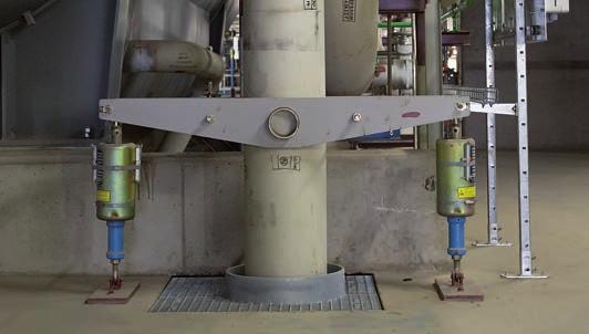
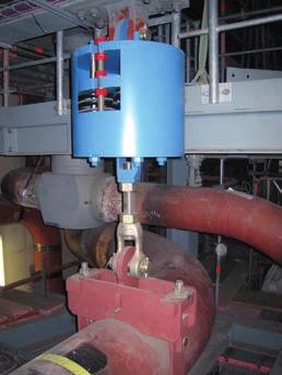
85 2 2.18


86 Installation and operating instructions Types 21, 22, 25, 26, 29, 28, 20, 27 upper connection travel scale blocking device name plate lower connection spring plate cover plate securing strap support tube Spring hanger Spring hanger Name plate for spring hangers Transport and storage When transporting, care must be taken that connecting threads and blocking devices are not damaged. When storing in the open air the hangers must be protected from water and dirt. 2 Delivery condition If not otherwise specified, LISG spring hangers are set and blocked at the desired cold position (installation condition). Special blocking devices fix the spring plates in both directions. The adjustment values can be read off the travel scale or name plate. Stamped on the name plate are: number and if required serial number set load and spring rate operating load and travel marking and commission number inspector On the travel scale the theoretical hot position is marked with a red sticker and the theoretical cold one with a white one. In addition the position of the spring plate on the travel scale is stamped with an X. The reading is made at the lower edge of the spring plate (at the upper edge for trapezes ). The production number is stamped on the body of the spring hanger. Depending on the connection the spring hangers are fitted at the top with an inner right-hand thread, a lug for connecting pins or a fixed support tube. The threads are greased and sealed with plastic caps. Depending on the design, the lower connection is fitted with a right-hand thread (turnbuckle) or, as with 25/26, consists of a support tube for the connecting rod. The spring supports s 28/29 are equipped with an adjustable support tube with a loosely seated but guided load plate. s delivered the support tube is screwed in and the thread greased. 3 Installation When installing, the requirements of the installation instructions for the piping systems should also be observed, especially the desired installation position of the connecting rods over the whole load chain. There are two possibilities: Spring hanger 21 (blocked) Spring hanger 25 (blocked) Spring hanger 22 (blocked) Spring hanger 26 (blocked)
87 Spring support 29 (blocked) Spring support 28 (blocked) ngulating spring support 20 (blocked) Sway brace 27 ) The connecting rods are to be installed at an angle to correspond to the expected horizontal displacement of the pipe systems. perpendicular position in operating condition is to be hereby expected. Cold position Rods vertical during plant operation ) The connecting rods are to be installed vertically for better controllability. controlled angled position is thereby permitted in operating conditions. hot position Rods vertical in installation condition Hot position cold position Uniform specifications should at all events apply for the whole plant. The connecting rods and points must be connected by force-locking. ttention must be paid to the minimum engagement depth of the threaded components. Installation of s 21, 22 The force-locked connection for 21 is produced by screwing the connecting rods into the upper and lower connection threads. The lower connection thread is designed as a turnbuckle. Type 22 has a pin-lug upper connection. For adjustment the available turnbuckle length in the spring hanger in each case can be used. Installation s 25, 26 Spring hangers s 25 and 26 are placed on the existing steelwork and correspondingly aligned. The position aligned is to be fixed against horizontal displacement. The force-locked connection is produced via the connecting rod, which is fed through the support tube and tightened and locked with two nuts. 2 load plate or ball bushing joint at top travel scale stop name plate base plate or ball bushing joint at bottom spring plate cover plate securing strap lock nut lock nut guide tube threaded tube lock nut guide rod Spring support 29 Spring support 28 ngulating spring support 20 Sway brace 27 angled arrangement Sway brace 27 simple arrangement 2.20

, or several adjustable ones ( 28).")

88 2.21 minimum engagement depth minimum engagement depth Minimum engagement depth of threaded rods by example of 21 The blocking device for spring hangers and spring supports s 21, 25, 29 and 20 consist of sheet metal lamellas adjustable to any desired load position. Up to 3 blocking devices can be inserted into a spring hanger. Installation of s 28, 29 The spring supports 28 and 29, are to be connected in the design location by welding or bolting the base plate to the building structure. The load distribution is applied through the load plate and an adjustable support tube ( 29), or several adjustable ones ( 28). To accommodate installation tolerances the support tubes may be further screwed out only to a maximum of 30mm. The instructions on page 7.12 are to be followed for the correct installation of the slide plates. Installation of 20 The angulating spring supports are fitted at the top with an adjustable ball bushing joint and at the bottom with a fixed ball bushing joint or an installation extension suitable for connection to a weld-on bracket 35 or to the dynamic clamps 36 or 37. fter alignment of the angulating spring support the lower weld-on bracket is attached to the surrounding structure (see installation instructions for weld-on brackets 35). The load distribution is applied through the upper pin connection (weld-on bracket or dynamic clamp) to the length-adjustable support tube. To accommodate installation length tolerances the support tube may be further screwed out by a maximum of 50mm. Installation of 27 The sway braces are fitted at the top with an adjustable ball bushing joint and at the bottom with a fixed ball bushing joint or an installation extension suitable for connection to a weld-on bracket 35 or to the dynamic clamp 36 or 37. The load presetting, and if necessary the free stroke, are adjusted at works according to customer specifications. fter alignment of the connection points the welding of the weld-on brackets and the connection of the connection pins of the brackets or dynamic clamps s 36/37 are carried out. The adjustable ball bushing joints permit regulation of the installation length by 37.5mm. 4 Deblocking The spring hangers/supports may only be deblocked when the set load is fully applied on all the supports making up a support system. If this is the case the blocking devices can be easily removed. If the devices are jammed, the load actually applied does not agree with the theoretical setting (see point 5, load correction). Procedures for s 21, 25, 29, 20 Removal of the securing strap: The securing strap is removed with an appropriate tool. Great care must be taken that the free ends of the metal strap do not snap upwards in an uncontrolled way. Removal of the blocking devices: The device is removed from the casing. When removing the blocking devices, proceed as a matter of principle in a systematic way, step by step, beginning with a fixed point or connection point. Never remove the devices by force! Storage of blocking devices: Type 29 with blocking devices attached
89 Removed blocking devices must either be stored separately or, for really safe keeping, fixed at the hanger by using the optional LISG permanent attachment. securing clamp fixing screw If the original blocking devices have been misplaced and the spring needs to be blocked, e.g. at revisions, they can be supplied by LISG at short notice. Procedure for s 22, 26, 28 Removal of blocking devices: Type 21, 22 Load adjustment can be carried out by loosening or tightening the turnbuckle. Type 25, 26 Load adjustment can be made by loosening or tightening the load nut. Type 20, 28, 29 Load adjustment can be made by adjusting the support tube of the spring supports. Load correction and adjustment of the free stroke, 27 Load adjustment is made by rotating the outer threaded tube (). For this, loosen the large lock nut (). To maintain the dimension the play thereby created must be balanced by readjusting the guide tube (C). free stroke can be set for the LISG sway braces. For this, the guide tube (C) opposite the inner guide rod (D) must be correspondingly screwed out (loosen middle lock nut ()). The working travel is reduced in the direction of compression according to the free stroke selected. D C 2 The blocking devices of s 22, 26 and 28 consist of threaded studs and nuts by means of which any load setting desired can be carried out. hydraulic cylinder The blocking devices are removed from the casing. Storage of blocking devices: Removed blocking devices must either be stored separately or, insofar as sufficient space is available and freedom of movement for the spring plate is allowed, screwed to the cover plate. 5 Load correction efore every load adjustment, under all circumstances the technical department responsible must be consulted. 6 uxiliary devices To facilitate load adjustment or deblocking, an auxiliary installation device can be supplied for the higher load groups. The load transfer is then taken up by means of a hydraulic pump. This is operated by LISG technicians. 7 Inspection and maintenance The flawless functioning of the spring hangers can be checked in every operating situation by noting the position of the spring plate. Under normal operating conditions no maintenance is required. hydraulic cylinder hydraulic cylinder (2 units) 2.22
90 Snubbers, rigid struts, energy absorbers, viscoelastic dampers, dynamic clamps 3 Snubbers, rigid struts, energy absorbers, viscoelastic dampers, dynamic clamps PRODUCT 3 GROUP


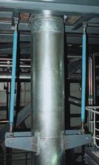

91
92 Snubbers, rigid struts, energy absorbers, viscoelastic dampers, dynamic clamps Contents Page Field of application Main products Instructions on use Snubbers 30, Design features Mode of operation and function Function tests Operational performance Permissible stress factors Rigid struts Mode of operation and function nergy absorbers Mode of operation and function Viscoelastic dampers 3D Mode of operation and function Pipe whip restraints 3R Dynamic clamps 34, 36, Mode of operation and function Dynamic clamps Selection tables Snubbers Snubbers Installation extensions Weld-on brackets nergy absorbers Viscoelastic dampers 3D Rigid struts Dynamic clamps 36, Shear lugs 3L Installation and operating instructions PRODUCT 3 GROUP


93 Field of application To avoid unacceptable stresses and moments in the piping systems, unplanned deflections in the piping or other plant components must be prevented. Thermal displacement must, however, not be obstructed! Dynamic events Whenever unplanned dynamic events occur, the support components in LISG product group 3 have the task of protecting the piping or other affected parts from damage. The unwanted jolting displacement of plant components can be caused by:. Internal events, for example: start-up / shut-down pressure impacts from valve operations water hammer boiler detonations pipe rupture. xternal events, for example: wind loads seismic events aircraft crashes explosions Components affected can be: pipe systems pumps valve assemblies pressure vessels steam generators boilers, heat exchangers Components in product group 3 For the absorption and transfer of dynamic load cases, specially designed supports are required. With product group 3, LISG provides a comp l ete system in which all fields of application are covered by the corresponding ideal component. In this way the implementation of optimum concepts is possible for the user. LISG product group 3 includes the following main products: Snubbers (shock absorbers), s 30 and 31 Rigid struts, 39 nergy absorbers, 32 Viscoelastic dampers, 3D Pipe whip restraints, 3R For proper implementation of the main components a complete range of connection possibilities are available: Installation extensions, 33 Weld-on brackets, 35 Dynamic clamps, s 36 and 37 Dynamic riser clamps, 34 The component connections are designed to be compatible with the LISG modular system and are subject to uniform calculation criteria. table of permissible loads can be found on page 0.6 of the technical specifications. The stress analyses forming the basis correspond to the international guidelines and codes and are additionally supported by practical experiments and testing. Design Report Summaries according to SM III NF and RCC-M are available. 3.1 Diagram of an operating basis earthquake (O...)
94 Main products 3 Snubbers 30, 31 The use of snubbers (shock absorbers) is pre-ferred in thermally operating plant components. In a dynamic event, snubbers provide an instantaneous, fixed, practically rigid connection between the component to be secured and the surrounding structure. In this way the dynamic energy from abrupt displacement can at once be transmitted and harmlessly dissipated. The thermal displacements during routine operation are not restricted. F Stroke s Rigid struts 39 If operational displacements have to be restricted, e.g. in zero crossings, rigid struts are used. These components form rigid connections from connection point to connection point and do not permit movement of any kind in the axial direction. s they are fitted with articulated bearings they permit slight lateral displacement. F rigid s nergy absorbers 32 If only minor operational displacement is expected at the load application point, energy absor - bers can be used. These components allow slight movements limited in the end positions by an adjustable gap. ny components affected are protected from overloading because, due to the design, excess dynamic energy applied is transformed into plastic deformation of the absorber. F s free stroke (adjustable) Viscoelastic dampers 3D Dynamic loads from mechanical, hydrodynamic or other external events can seriously damage plant components and pipe systems. Viscoelastic dampers can absorb these vibrations and load peaks. highly viscous fluid thereby absorbs the kinetic energy and dampens any vibrations. s b F dissipated energy (working stroke) s Pipe whip restraints 3R Pipe whip restraints are a specially designed of pipe restraints. In the event of a bursting pipe system, it will transform the suddenly released kinetic energy into plastic deformation and hold the pipe in a safe position. ny overloading of the steelwork is thereby prevented. tension dissipated energy elongation 3.2
95 Instructions on use The components in product group 3 are dynamically stressed. When using them, the following points must be observed for their effective functioning: In the conception of dynamic fixed points the rigidity of the whole system, i.e. of all components in the support chain, must be taken into account. 2. In the selection of the sizes to be used, the sum of all loads occurring must be considered special design special design 3. For given loads it must be clearly determined beyond all doubt which design load (H, HZ, HS and/or Level,, C, D) the data corresponds to. The table of permissible loads on page 0.6 of the technical specifications must be observed. 4. The stroke length of snubbers should not be fully utilized. travel reserve of 10mm in both directions is recommended When arranging components, sufficient lateral freedom of movement must be ensured so that no jamming occurs at the connections In the case of parallel arrangement of snubbers it is recommended to take load reserves into account. Instead of 50% in each case, both snubbers should be designed to take at least 70% of the calculation load The installation drawings should clearly indicate the degree of freedom of possible angulation of the components ny necessary torque values for threaded connections in the structural attachments should be indicated. special design 9. efore commissioning the plant, all support points should once again be visually inspected The LISG instructions for commissioning are to be observed, as well as inspection and maintenance recommendations special design 3.3


96 Snubbers Type 30, 31 3 LISG snubbers have stood the test of time in practical applications for well over four decades and have thereby proven their outstanding reliability. xtensive operational experience has, together with continuous further development, led to highly acclaimed state-of-the-art products and to worldwide market leadership. ccess to snubbers after installation is almost always difficult and, due to possible danger to personnel from radiation when installed in nuclear power plants, is subject to stringent safety regulations. For this reason the most stringent demands are made on reliable, maintenance-free, continuous functionality. For the reliable operational safety of snubbers, besides the function principle and whole design, the highest quality of critical components is crucial: sealing systems piston and rod guides hydraulic fluid sliding surfaces corrosion-resistant materials corrosion-free interiors control valves The most common cause of failure in snubbers is usually premature wear and tear and corrosion. For this reason LISG snubbers are made of corrosion resistant materials. In addition, any form of metallic contact within the unit is eliminated by the use of special guide bands. Snubbers 30 t LISG, sealing systems, guides and hydraulic fluid are certified by reliable qualification procedures to give at least 23 years of troublefree operation under normal operating conditions in a nuclear power station. The following quality features prove the superior functioning and long life of LISG snubbers: corrosion-resistant materials special sealing systems vibration-resistant special guides pressurized hydraulic systems dynamic functional behavior exchangeable valves ( 31) tested and approved for min. 23 years maintenance-free operation 60-year design life certified by suitability tests according to KT approvals according to SM-NC 3800 Final inspection of snubbers


 The compensating reservoir is sealed against the atmosphere by a preloaded piston so that slight excess pressure")


97 Design features Snubbers Type 30, 31 Design features The snubbers form a closed hydraulic system without external bolted pressure fit tings. The individual parts of the units are connected without welding by precision fit and screw connections, and are mechanically secured. s a protection against corrosion, LISG snubbers are manufactured exclusively from corrosion resistant materials. The connecting lugs are made of electro galvanized carbon steel. The guides on piston rods and pistons are made of a special friction-resistant, non-metallic material. thermal resistance radiation resistance resistance to wear, especially highfrequency vibrations good restitution behavior ( shape memory ) good dry run characteristics limited tendency to diffusion in seal surfaces minimal transfer from static to sliding friction (stick-slip effect) The compensating reservoir is sealed against the atmosphere by a preloaded piston so that slight excess pressure is maintained in the hydraulic system. This ensures the permanent functioning of all seals and the positive feed of hydraulic fluid to the cylinder regardless of the installed orientation. The control valves are vital for dynamic function. To achieve high functional accuracy the valve parameters have been optimized by extensive testing and special calculation models. Seals The decisive design features for long-lasting function are the sealing systems. esides the hydraulic fluid and guide bands, they form part of the non-metallic materials and are therefore exposed to natural aging and wear. The most important requirement for a long-lasting sealing effect is the choice of the correct sealing material. The crucial factor thereby is the seal s restitution behavior ( shape memory ) or compression set, providing the lowest possible stress relaxation. For optimum utilization of material properties the special shape of the seals are also important, while for final functional efficiency the best combination of the following features are critical: special mixture of fluorelastomer VITON has proved to offer the optimum solution here. In addition, the following prerequisites must be fulfilled to gain full benefit from the special characteristics: special sealing geometry supporting composite materials optimum consistency (mixture proportions) optimized hardening precision of sliding surfaces design of the installation spaces for defined preloading of the seals Ordinary seals do not fulfill these demands in snubbers and have been shown to lead to premature failure. For this reason, as early as 1984 LISG, in collaboration with a renowned seal manufacturer, began to develop specific sealing systems that have since proved themselves in practice. In 1992, after other successful certification procedures through artificial aging and long-term trials, a certification process for LISG snubbers was conducted on behalf of a uropean nuclear operator. The result: a maintenance-free operating period of min. 23 years in nuclear applications was confirmed. 3.5

. b Name plate with all technically relevant data.")

98 Design features Snubbers Type 30, 31 3 Type 30 Connection possibilities special range of connection components and adapters are available, so that in the event of an exchange the existing connections on site can still be used. connection special lugs short installation extension without possibility of length adjustment standard installation extension with possibility of length adjustment b f e c d flange for connection to existing installation extensions 33 connection a Control valves to achieve greater functional accuracy ( 30: internal). b Name plate with all technically relevant data. c Control indicators: The piston position of the snubbers can be read off on all sides via the scale rings on the snubber casing. robust steel casing connected to the piston rod serves as an indicator and at the same time protects the piston rod from mechanical damage, pollution and radiant heat. d Connection lugs (carbon steel) electro galvanized (only 30). e Inspection glass in the compensating reservoir / indicator bar. The fluid level of the reservoir is shown by the position of the reservoir piston. For 30 the minimum level can be checked through the inspection glass; for 31 there is a marked indicator bar at the rear of the external compensating reservoir. f The reservoir is sealed against the atmosphere by means of a spring loaded piston so that slight excess pressure in the hydraulic system constantly keeps the seals under slight pressure ( 30: located inside). 3 Corrosion resistant materials. 3 Radiation-resistant, wear-resistant seals. Connection possibilities: See pin diameters of weld-on brackets 35 or dynamic clamps in product group 3. f b a e c Type 31 For details of design and materials see technical specifications page

 the valve is held open by spring force and the hydraulic fluid can freely flow from one cylinder chamber into the other.")

 takes place.")

 work similarly to those on 30.")

99 Mode of operation and function Snubbers Type 30, 31 In the event of an impact on the component to be secured, an instantaneous, practically rigid connection is to be made between the component and a fixed point on the surrounding structure Function Control valves The function of the LISG hydraulic snubbers 30 is controlled by a main control valve () positioned axially in the hydraulic piston (). On slow displacement of the piston (m 2mm/s) the valve is held open by spring force and the hydraulic fluid can freely flow from one cylinder chamber into the other. On rapid piston displacement above a velocity limit (approx. L2mm/s), back pressure develops on the valve disk and closes the valve. The hydraulic flow is interrupted and the displacement blocked. Due to the compressibility of the hydraulic fluids, damaging load peaks are also prevented. On displacement in pressure direction, the compensating valve (D) also closes almost synchronously with the piston valve. If the pressure on the closed valve is reduced, e.g. by reversal of the displacement direction, the valve opens independently. Function diagram, snubber 30 C D co-axially arranged compensating reservoir (C) takes place. The connection between reservoir chamber and the working cylinder is regulated by the compensating valve (D). C Function diagram, snubber 31 Large bore design 31 The mode of functioning of the LISG hydraulic snubbers 31 is based in principle on the same concept as for 30. The particularities of size require a different arrangement of the compensating reservoir (C). t the same time a different arrangement of the valves are also necessary. The valves () work similarly to those on 30. Here too, the flow of hydraulic fluid in the respective direction of movement is interrupted by closure of the corresponding valve if a certain limit of velocity is exceeded. s both valves stand with the given arrangement indirect connection with the compensating reservoir, an additional compensating valve is unnecessary. 38 special design ypass To prevent the valves from remaining in a blocked condition they are designed with a bypass system. This permits a gentle after-flow at cont inuous force and ensures the safe opening of the valves in both cylinder chambers through rapid pressure balance. The compensating valve works synchronously with the main valve in the same way. Compensating reservoir To balance the piston rod volume, as well as to change the volume of hydraulic fluid on change of temperature, volume compensation via a In service testing The valve system is designed to be replaceable, so that all the snubbers 31 need not be removed for routine function testing. In this way, in the event of a recurrent test only the valve units are replaced by a previously cert ified valve assembly. special shut-off device thereby prevents loss of fluid. The replaced valve assembly can subsequently be tested on a test snubber and prepared for future use. This design meet the intent of sub component testing according to SM OM Code, Subsection ISTD. 3.7

100 Function Tests Snubbers 30, 31 3 specially stringent safety demands in the nuclear field require flawless proof of the function parameters for snubbers. This applies both to initial delivery inspection and to recurrent tests. The LISG test technology is permanently improved in-house and complies with the most up-to-date technical stand ards. The test benches function as dynamic Hydropuls units with optional force- or travel-controlled excitation. The frequency bands range from Hz, and the test loads from 0.5 up to 8600kN. For standard tests LISG has test facilities of its own manufacture in different factories and in various sizes. Mobile units are often used on site at customer request. The test facilities are used worldwide today and are operated by the customers own personnel. Variable test programs permit the testing of all snubber makes. LISG test benches are also manufactured for customers. ll LISG s test benches are calibrated at regular intervals on the basis of DIN N ISO 7500 with calibrated load cells and measurement amplifiers. Inspection report with test diagrams page 1 Inspection report with test diagrams page 2 Quasi-static function tests Dynamic function tests a Drag force [kn] b Lockup speed [mm/s] c ypass speed [mm/s] d Load and travel amplitude 3.8


101 Operational performance Snubbers Type 30, 31 Operational performance On dynamic loading, LISG snubbers offer a constant, predictable, functional performance subject to the load spectrum. Specified function values LISG snubbers comply, as a standard, with the following functional data. The values apply to alternating or dynamic loading. The specified values correspond to the recognized international specifications and practical requirements. Observation of the values is certified and recorded during factory testing. y means of design adaptation or use of special oil special parameters can be taken into account. travel range 8, 2, 9 a travel range 3 (stroke 300) travel range 8 (stroke 100) travel range 9 (stroke 200) piston rod travel s b at F N, R t b and 1-35Hz m 6mm m 8mm m 10mm m 12mm piston rod play s a (lost motion) lockup velocity at R t b bypass velocity at F N und R t b m 0.5mm d up till load development on change in load direction 2-6mm/s 0.2-2mm/s e maximum resistance against movement (drag force) c for F N m 8kN 2.5% F N for F N L 8kN largest value of 200N or 1%F N largest value of 300N or 1.5%F N 1%F N a Travel range 8=100mm, travel range 2=150mm, travel range 9=200mm. b R t = room temperature (20 C 6 4 C). t ambient temperatures of 150 C (short duration, max. 1h) the piston rod travel may be increased by up to 50% due to reduced fluid viscosity. c Measured at a constant piston rod speed of approx. 0.3mm/s. reakaway force is kept at less than 1.5 of given values. F N = nominal load. d If required, s a can be increased to M 0.5mm (KT ). e ypass velocity l 0.2mm/s on request. Force F F F Faulted F F mergency F N rigidity K= 2F N s b t piston rod travel s s a s b -F N s -F mergency -F Faulted t sb Force travel diagram Force and travel amplitudes 2500kN test bench at LISG 3.9

 ambient pressure continuous operation 0.")
102 Permissible stress factors Snubbers Type 30, 31 3 Operational demands LISG hydraulic snubbers are designed as standard for the following operational demands. The specified values are certified by KT suitability tests. Other values can be agreed in exceptional cases by design adaptations. continuous operation max. 80 C loading due to ambient temperature short-term max. 1h/temp. cycle max. 150 C max. 40h/year relative air humidity at C 100% wet steam atmosphere up to max. 150 C X=1 energy dose cumulative 10 5 /kg =10 5 gray (=10 7 rad) ambient pressure continuous operation bar short-term 5 bar excess pressure Test facilities for snubbers in Zeven plant, Germany The values apply to the whole snubber, incl. seals and hydraulic fluid. The data for the fluid are: hydraulic fluid (silicon oil) setting point 50 C flash point L 300 C ignition point P 500 C Resistance to fatigue Proof of operational durability is based on the following accumulated load cycles: nominal load F N...load cycle 10%...2,000,000 50% ,000 80%... 20, % (Level /)... 10, % (Level C) % (LeveI D)...10 It should be taken into account that the number of possible active parameters, such as frequencies, amplitudes, forms of vibration, effective directions, as well as any possible simultanity, allow no uniform definition of permanent operational vibrations. The load cycle figures correspond to an assumed maximum dynamic load capacity from diverse load events over a period of 40 years. They also comply to the requirements of the test programs of the KT suitability tests performed. The test results certify that the snubbers endure these loads while maintaining their operational capability. Due to their specially designed guides, the snubbers are extremely resilient to any continuous operational vibrations. This is proven by confirmed practical experience. Special testing of snubbers 31. Test load up to 8600kN. 3.10


103 Mode of operation and function Rigid struts Type 39 In contemporary support concepts, rigid struts play an important role in the safe guiding of pipe systems. The reliable positioning of piping is a crucial factor in the operational safety and long life of the whole system special design Typ Typ 39 Tasks The LISG rigid struts 39 provide a range of important functions for the operational safety of pipe systems: Transmission of displacement from unplanned load events (see page 3.1) Guiding of pipe systems for the control of planned thermal displacement direction Stabilization of flexible pipe systems by fixed so-called zero positions Design of axial stops Mode of operation Rigid struts perform as hinged rigid connections between pipe systems and structure. No resistance is offered to slight displacements in the pipe system around the angular displacement of the rigid struts. Movement axially to the rigid strut is not possible. Design The rigid strut consists of a rigid body with a ball bushing joint for connection at each end. ttachment to the structure is made via a weldon bracket 35 and connection to the piping using dynamic clamps from product group 3. The selection tables for connecting components can be found on page 3.22 or pages 3.29 to Up to load group 8 the body consists of a tube tapered at the ends, depending on alternative manufacturing technologies. The shape corresponds to the flow of force and permits a favourable power / weight ratio. The connections are ball bushing joints acting as turnbuckles with right- and left-hand threads, permitting length adjustment within a range of 150mm or 300mm. Flat faces on the body of the tube allow the safe use of a wrench and so facilitate length adjustments in the installed condition. The ball bushing joints are provided with fine threading to guarantee secure locking. The bodies are produced in standard lengths and are available from stock. LISG rigid struts are suitability-tested according to KT and designed in accordance with the SM-PV Code. Typ e c f d b a c a surface with standard paint coating. b flat face for easy adjustment. c length-adjustable with right-hand / left-hand threads. d body, free of welding up to load group 8. e electro galvanized ball bushing joints with fine thread. f safe locking of ball bushing joints by means of fine threads and electro galvanized lock nuts. 3.11
 within a range of w 25mm. In this range the pipe system can move freely without resistance.")


104 Mode of operation and function nergy absorber Type 32 3 Mode of operation and function The energy absorber functions by means of an adjustable free stroke to absorb thermal displacement. The adjustment of the free stroke can be carried out (for medium sizes) within a range of w 25mm. In this range the pipe system can move freely without resistance. Dynamic events, however, are limited in their movement by the use of stops. The forces arising are thereby led into the building structure up to the specified nominal load and, above that, transformed into deformation energy. Connected components are in this way protected in a controlled manner from overloading. For this reason energy absorbers are ideal as protection: against water hammer as a substitute for complex framework constructions as whip restraints If such an event has occurred, the forward thrust of the disk affected can be read from the position of the indicator bar (G). For further use of the energy absorber the free stroke on the adjustment device (H) only needs to be re-regulated for the new position. Corresponding procedures can be repeated up to maximum deformation travel (s). Further information is available on page Installation The energy absorbers are designed in accordance with the load group in product group 3 (dynamic components) and are correspondingly compatible in respect of loads and connections with the connection components in this product group. Please also note the instructions on page 3.1. nergy absorbers restrict dynamic deflections and transform forces above the nominal load into deformation energy. The steelwork is thus protected. nergy absorber, used instead of a double guide. In this way the framework can be avoided. free stroke (compression) F taper disks free stroke (tension) C D length adjustment adjustment of free stroke H indicator for deformation energy (absorbed energy) G The design consists of an austenitic tubular casing () with defined size, into which taper disks () with defined force have been pressed. The tube is sealed with a fixed base (C) fitted with a connecting lug (D). The force transmission over the whole unit is made via the stops () and the push rod (F). If a dynamic event exceeds the compression force of the taper disks, the taper disk affected is driven forward and widens the cover tube. In this way the excess force is diverted from the connection components by transformation into deformation energy. Function certification LISG energy absorbers have gone through an exhaustive test program to prove their functional reliability. In numerous dynamic and static stress tests, as well as load capacity tests, their safety has been clearly demonstrated. nergy absorbers are maintenance-free during operation and require no in-service testing. Measured force/travel path with oscillating loads L nominal load 3.12


 Hysteresis of a viscoelastic damper F travel s a e f c d b g")
105 Mode of operation and function Viscoelastic damper Type 3D Dynamic loads from mechanical, hydrodynamic or external events can severely damage pipe systems and other plant components. Viscoelastic dampers can considerably reduce such vibrations. Vibrations occur through inner events from mechanical or hydrodynamic processes, or in the case of external events such as wind loads, traffic vibrations or earthquakes. Impermissibly high vibrations can thereby cause serious damage to pipe systems. y means of special components they must be protected. To avoid stresses in the whole system, displacements from thermal expansion in the piping system may only be minimally obstructed. Viscoelastic dampers have proved in practice to offer reliable protection for pipe systems and installations. In particular, vibrations caused by sudden peak loads can be reduced to an acceptable level by such dampers. The LISG viscoelastic damper consists of a casing filled with viscous fluid that allows relative displacement between the connecting plates and at the same time dampens in all directions, dissipating the kinetic energy (transformed into heat). Viscoelastic dampers transmit only dynamic loads, not static ones. The reaction force of the damper is thereby proportional to the velocity and freq uency of the vibrations. LISG offers fluids with varying damping characteristics in relation to application temperature and frequency. Construction of the LISG viscoelastic damper load dissipated energy s b (displacement range) Hysteresis of a viscoelastic damper F travel s a e f c d b g Viscoelastic damper with transport brackets without offset ab connecting plates c name plate d position indicator e maintenance-free dust cover f transport brackets g inner connection thread M16 for transport purposes 3 load range 2.5kN to 100kN 3 frequency range up to 35Hz 3 temperature range from 10 C to 80 C 3 travel range up to 50mm Viscoelastic damper with adjusted offset 3.13


106 Pipe whip restraints Type 3R 3 Pipe whip restraints Special designs in the field of dynamic pipe supports are pipe whip restraints. eside energy absorber 32, a design with round-steel U-bolts has proved widely successful, especially for large loads. OD tension dissipated energy Pipe whip restraints are common in nuclear installations and are designed to instantaneously absorb the kinetic energy of bursting pipe systems in faulted conditions. For this, the elongation behavior of the surrounding steel U-bolts is utilized; these are designed to cope with the dynamic forces to be expected. elongation Pipe whip restraints are designed according to the customer s design parameters and manufactured by LISG as special components. Pipe whip restraints are important as safety elements and are therefore subject to stringent quality requirements with regard to design and manufacture. s the result of countless deliveries to modern nuclear installations LISG has clearly proved its qualification for the supply of these components. 3.14
107 Mode of operation and function Dynamic clamps Type 34, 36, 37 For the dynamic supports the pipe clamp design must also be carefully considered. Despite properly functioning main components (rigid struts, snubbers, energy absorbers) the functioning of the whole system can be seriously affected by faulty pipe clamps. Function In the high temperature range and/or over a longer period of time, friction fit clamps cannot safely transmit dynamic loads, even with bolt pre-stressing, due to the creep strength behavior of the materials (long-term fatigue). ven over-sized bolts, which might under certain circumstances severely constrict the piping ( pipe squeezers ), are not solving the problem. typical fault is a clamp design that is too soft, so that the necessary stiffness rule is not achieved ttention must also be paid to connections to clamps free of play To prevent constraints, sufficient space must be ensured for lateral displacement in the event of pipe system movements The selection tables are classified according to pipe diameters. The designation for the relevant clamp is found by way of the temperature ranges and permissible loads. fter that the installation dimensions must be checked against the scale drawings. Special attention must be paid to the lug connections on the rigid struts, snubbers or energy absorbers. If the standard pin connection d1 is not suitable, a different weld-on bracket 35 can be supplied. The dimension of the clamp is changed according to the table below. If the customer order does not show a particular modification of the layout, the bracket connection is fitted so that the main angulation range runs along the pipe axis. Friction-fit clamp (static) shear lug To transmit dynamic loads, clamps are required that absorb dynamic forces and transmit them further. Dynamic forces are created by alternating loads; displacement can thereby result due to eccentrically applied forces. The dynamic clamp should therefore be form-fitted (shear lugs) to prevent contortion. In this way, defined, verifiable conditions are produced. Certification is the responsibility of the pipe system designer. Type /2/3 Type /2/3/4/5/6 Form-fit clamp (dynamic) The shear lugs keep the dynamic clamps in the expected force direction and are practically unstressed. Lateral forces would not occur under dynamic load cases because friction forces between the pipe and the clamp insure the firm positioning. Type 36 with shear lug 3L 3.15 Due to the minimal forces to be absorbed the weld seam stresses can be minimalized, despite the small shear lug sizes. s a rule they lie under 35% of the yield stress (creep strength) limit for load case H (level /), in accordance with the permissible SM or DIN values. From a table the LISG shear lugs can be selected on page Dynamic clamps 36, 37 To achieve the optimum solution in each case and at the same time the most favorable performance/weight ratios, LISG offers 4 standard designs. Type /5 theor. load group Type /8/9 max. load group of dynamic clamps 1, dimension reduction about i 1, Reduction of the max dimension for dynamic clamps 36 and 37 on selection of a smaller connection than given in the column 'max. load group' in the selection tables.
.")

 are designed for dynamic operation with snubbers or rigid struts according to")


108 For the support of austenitic pipe systems, the pipe clamps can be fitted with stainless steel inlay plates made of stainless steel (X5 CrNi 1810). These plates must be ordered separately, see page 4.7. Dynamic clamps as statically stressed clamps The specified permissible loads (in the selection tables on pages 3.29 to 3.43) are designed for dynamic operation with snubbers or rigid struts according to the load spectrum on page Special designs In some cases special designs are advisable in addition to the dynamic clamps 36 and 37. In particular, for parallel and angulating arrangements, standardized design and calculation methods have been proved successful. 3 Special design 37 with pin of weld-on bracket in pipe axis direction The dynamic clamps can also be exposed to permanent static stress. For this, the specified permissible stresses are reduced according to the following table: Special clamp for angulating arrangement 38 special design design temperature permissible permanent tension stress up to 350 C 100% 351 C 450 C 100% 451 C 500 C 80% 501 C 510 C 80% 511 C 530 C 65% 531 C 560 C 55% 561 C 580 C 65% 581 C 600 C 60% These specifications relate to the creep strength dependent on time in the 200,000 h range at temperature M 450 C. Dynamic pipe clamp 34 with snubbers and twist restraints special design special design Horizontal axial stop with rigid strut 39 and pipe clamp 34 incl. spacer 3.16

.")


109 Dynamic clamps Type 34 Dynamic stresses frequently arise in the direction of the pipe axis (e.g. from shock impacts or other forms of excitation). To absorb these loads the special dynamic clamp 34 was developed. In vertically and horizontally running pipe systems, special clamps are being increasingly used for the defined determination of the pipe system positioning and also for the absorption of dynamic stresses in the direction of the pipe axis. The loads thereby occurring must be distributed via a form-fitting connection to the piping (trunnions). For this purpose LISG has developed the dynamic clamp 34. Type 34 with snubbers and position-securing devices Type 34 as axial stop with spacer Type 34 The basis of this design was the long time successful box-frame clamp 46/48. The load distribution in dynamic clamp 34 is effected by the use of reinforced cross-beams with weld-on brackets 35 for connection to the dynamic main products 30, 32, 39. Design For the design of the dynamic clamps 34 the following parameters are required: Securing positions Position securing measures ensure that the clamp cannot angle around the pipe (with the trunnion as pivot). The position-securing device is not dynamically stressed. It is either a recess in the trunnion socket-hole or additional plates. Type 34 with snubbers 30 and twist restraints load (dynamic, static) pipe system temperature insulation thickness span width of the connections connection size and alignment of weld-on brackets 35 trunnion sizes trunnion tolerances position (horizontal/vertical) main components connected ( 30, 39, 32) twist restraint/recess dimensions if required spacer if required Type 34 with recesses Type 34 with additional plates Due to the wide range of possible combinations and design parameters, dynamic clamps 34 are designed individually on request. Type 34 with rotated trunnion hole and snubber


110 3 Horizontal axial stop with rigid struts 39 and pipe clamp 34 Pipe system secured with snubber 30 on dynamic clamps
 are electro galvanized.")

111 Snubbers Type 30 Snubbers to Serial standard design. Delivery from stock. Only corrosion-resistant materials are used. The connecting lugs attached by a connection thread (material P250GH, C45+QT, S3552, 668Cl. C/F, S299) are electro galvanized. connecting lug name plate travel indicator sight glass (fluid inspection) ball bush piston rod cover SG 6 6 Ø D f d 3 max. 90 R F c F nom. load emergency [kn] a Level C b stroke e Ø D Ø d 3 f c min c weight max F d R S G Order details: snubber with 2 weld-on brackets marking: a See technical specifications, table: permissible loads (page 0.6) and welding of weld-on brackets (page 3.22). b Usual design load for earthquakes and similar load cases. See also technical specifications on page 0.6. c min = piston rod retracted max = piston rod extended To bridge greater installation lengths, installation extensions 33 (page 3.21) can be used. d On replacement of other makes, the connection dimensions such as pin diameters and lug lengths can be adapted to the connection designs already existing in the plant. e If required, snubbers with longer strokes can be supplied. f Connection possibilities: see pin diameters of weld-on bracket 35 or dynamic clamps in product group 3.


 and welding of weld-on brackets (page 3.22). b Usual design load for earthquakes and similar load cases. See also technical specifications on page 0.6. c min = piston rod retracted max = piston rod extended.")
112 Snubbers Type 31 3 Snubbers to connecting lug ball bush SG max G travel indicator e name plate valves fluid level indicator L d Ø D H Snubbers 31 are specially conceived for the absorption of particularly heavy loads. They are mainly used in nuclear power stations to protect steam generators and large pumps. Due to the normally very restricted installation space they are typically custombuilt for the given conditions. The table on this page therefore serves as general orientation for initial planning. The body and connecting lugs are made of high-tensile stainless steel castings. R f d 3 c F R nom. load emergency [kn] a Level C b stroke e Ø D Ø d 3 f c min c max F G H L max weight d R S G Order details: snubber with 2 weld-on brackets marking:... a See technical specifications, table: permissible loads (page 0.6) and welding of weld-on brackets (page 3.22). b Usual design load for earthquakes and similar load cases. See also technical specifications on page 0.6. c min = piston rod retracted max = piston rod extended. d L max at 80 C. e Design of travel indicator for travel range 8 (100mm stroke). f Connection possibilities: see pin diameters of weld-on brackets 35 or dynamic clamps in product group 3. LISG snubbers 31 are fitted with exchangeable valves for in-service tests on site. Snubber 31 in special configuration 3.20


113 Installation extensions Type 33 Installation extensions to Serial standard design. Type 33 installation extensions are used if greater installation lengths are required. Connection to the snubber or energy absorber is made at the cylinder base. y means of serially-produced screw connections the change over easily be made from standard connecting lugs to installation extensions. This also applies to special connections, which are particularly useful when exchanging other makes, as in this way the connections on site can still be used. Further connection possibilities can be found on page 3.6. n exceeding of the maximum lateral displacement of w 6 is to avoid. Material: tube ball bushing joints P355NH P250GH C45+QT S CrMo4+QT Order details: installation extension L =...mm for hydr. snubber or energy absorber nom. load [kn] snubber stroke a For middle piston position. a a Ø d 3 c D max b Installation dimensions larger than max. possible on load reduction. Smaller L dimensions can also be supplied without adjustment possibility. a b min a b max LW 37.5 b min LW 37.5 b max weight +per 100mm a minimum thread engagement depth L min Ø D Lw37.5 extension tube lock nut Ø d 3 c ball bushing joint c Connection possibilities: see pin diameters of weld-on brackets 35 or dynamic clamps in product group
![Weld-on brackets Type 35 b d3 R c nom. load [kn] a C Ø d 3 b F L R a See technical specifications, table permissible loads (page 0.6) and welding of weld-on brackets (as shown below).](/docs-images/93/114255555/images/114-0.jpg "F L b Fit: H7 f8. weight 35 19 13 3 25 32 12 10 30 9.5 42 13 0.2 35 29 13 4 25 32 12 10 30 9.5 42 13 0.2 35 39 13 8 30 37 12 12 34 10.5 46 15 0.3 35 49 13 18 35 43 13 15 40 12.5 52 18 0.")


.")
114 Weld-on brackets Type 35 b d3 R c nom. load [kn] a C Ø d 3 b F L R a See technical specifications, table permissible loads (page 0.6) and welding of weld-on brackets (as shown below). F L b Fit: H7 f8. weight Weld-on brackets to Serial standard design. This component is designed for connection of snubbers 30 and 31, energy absorbers 32 and for rigid struts 39, 16, 20 and 27 and provides for attachment to the struc ture. The brackets are made of the easily weldable carbon steel S3552 and the precision-fit stainless steel connecting pins. Order details: weld-on bracket If required, weld-on / bolt-on brackets in larger sizes are suppliable a =15 b = 6 a =30 b = 6 a =45 b = Weld-on brackets should always be arranged so that the max. angulation results in the direction of the greatest thermal expansion during oper - ation ( a ). The lateral deflection is restricted to w 6 ( b ). Misalignment of the weld-on brackets should be avoided due to the restricted possibility of movement caused. The minimum weld seam thickness a for weldon brackets 35 is dependent on the ang u l - ations a and b. In the calculations a permissible stress of 90N/mm 2 in load case H (level /) was assumed. a a b Max. angulation 35 b On increasing the angulation a to 90, the perm issible loads are reduced by approx. 15% on constant weld seam thickness ( at a = 45 ). The basis for the permissible loads is provided by the relevant load table ( technical specifications, page 0.6). 3.22
 dd 3 s b b s F t 1 t 2 free stroke (tension")
115 nergy absorber Type 32 nergy absorber to Serial standard design. free stroke adjustment indicator of absorbed energy total length adjustment minimum thread engagement depth 6 SG 6 Ø D d 3 d free stroke (compression side) dd 3 s b b s F t 1 t 2 free stroke (tension side) c R a If the nominal load is exceeded, the increasing force and displacement are transformed into deformation energy. b Max. deformation travel in compression and tension directions. c dimensions on middle position of the free strokes t 1 /t 2 and length adjustment dimension. If t 2 changes, the dimension is correspondingly reduced or increased. d Connection possibilities: see pin diameters of weld-on brackets Type 35 or dynamic clamps in Product Group 3. nom. load [kn] a s b t 1 t 2 Ø D Individual application The standard designs shown in the table above represents only part of the suppliable range. The products can be adapted by LISG to the particular requirements of the user. This applies especially to those cases where loads and strokes exceed standard parameters. Ø d 3 weight d c F R S G w w w w w w w on request Order details: energy absorber t 1 = mm, t 2 = mm marking:


116 3 Snubbers 31 prior to delivery Type 31 Commissioning of
117 Viscoelastic damper Type 3D.. 44-D Viscoelastic damper 3D D to 3D H1 44-D Selection and dimensions When selecting viscoelastic dampers attention should be paid to the temperature existing on site. These dampers are available for application temperatures ranging from 20 C to 80 C, whereby the various damping media cover a temperature range of 10 C in each case. For this reason the correct selection of application temperature is important. -middle s s = working range round the mid-position The choice of damper size depends on the nominal load. The offset in horizontal and vertical directions must be considered for the cold load position. For LISG dampers in the 44-D series this amounts in each case to w 40mm in horizontal/ vertical directions. The operation of the dampers should be in the center position. In order to achieve the necessary damping resistance, the viscous dampers should not exceed a tolerance of w 20 mm from the center position in any operating condition. efore any start-up the dampers require preheating at operating temperature. k k C Ma a b Further information about vibration reducing products are to be taken from the product catalogue VICOD. load range: 2.5kN up to 100kN frequency range: up to 35Hz temperature range: 20 C up to 80 C (in 10 C stages) offset (cold position) to mid-position: up to W 40mm (horizontal/vertical) The table values are minimum values at ordered working temperature. t lower temperatures the damping resistance increases. If required, the equivalent stiffness (kn/mm) can be given in vertical and horizontal directions. a Inner thread for transport ring screw. Order details: viscoelastic damper 3D.. 44-D marking: nominal load: kn offset: x: mm, y: mm, z: mm operating temperature: C nominal load [kn] k k C s a b M a weight 3D D D D D D M D D M D D M D D M D D M D D M D H1 44-D M nominal load [kn] 5 [Hz] vertical damping resistance [kns/m] [Hz] [Hz] [Hz] [Hz] [Hz] 35 [Hz] 5 [Hz] horizontal damping resistance [kns/m] [Hz] [Hz] [Hz] [Hz] [Hz] 3D D D D D D D D D D D D D D D D D H1 44-D [Hz]


118 Viscoelastic dampers Type 3D.. 33-L, 3D.. 55-L 3 Selection and dimensions When selecting viscoelastic dampers the temperature on site is important. Series 3D....-L is designed for use in a temperature range from -10 C up to +40 C. In this temperature range the damper functions with relatively constant characteristics. The values were determined for a temperature of 20 C. -middle s s Viscoelastic dampers 3D L to 3D L The choice of damper size depends on the nominal load. The offset in horizontal and vertical directions must be taken into account for the cold load position. For LISG dampers in the 33-L and 55-L series it amounts to w 30mm and w 50mm respectively in horizontal / vertical directions. k k C Ma The operation of the dampers should be in the center position. In order to achieve the necessary damping resistance, the viscous dampers should not exceed a tolerance of w 20 mm from the center position in any operating condition. The dampers do not need to be preheated to operating temperature before start-up. The table values are minimum values at 20 C. t lower temperatures the damping resistance increases. If required, the equivalent stiffness (kn/mm) can be given in vertical and horizontal directions. b load range: 2.5 kn up to 50 kn frequency range: up to 35 Hz temperature range: 10 C up to + 40 C offset (cold position) to mid-position: up to W 30 mm ( 3D.. 33-L) up to W 50 mm ( 3D.. 55-L) (horizontal/vertical) nominal load [kn] k k C s a b M a a weight 3D L M D L M D L M D L M D L M D L M nominal load [kn] k k C s a b M a weight 3D L M D L M D L M D L M D L M D L M nominal load [kn] 5 [Hz] vertical damping resistance [kns/m] [Hz] [Hz] [Hz] [Hz] [Hz] 35 [Hz] 5 [Hz] = working range round the mid-position Further information about vibration reducing products are to be taken from the product catalogue VICOD. a Inner thread for transport ring bolt Order details: viscoelastic damper 3D.... L marking: nominal load: kn offset: x: mm, y: mm z: mm operating temperature: C horizontal damping resistance [kns/m] [Hz] [Hz] [Hz] [Hz] [Hz] 3D 05..-L D 10..-L D 15..-L D 25..-L D 40..-L D 50..-L [Hz] 3.26

119 Rigid struts Type 39 Selection When selecting rigid struts from the below tables, these points must be noted: 1. The specified operating load must be covered by the nominal load. 2. The load group is determined at the same time by the nominal load. 3. The adjustment range available for the rigid struts is given for the specified installation length. 4. The weight is specified at the intersection between load group and adjustment range. If the intersection lies below the red boundary line, it is a matter of an extended length with reduced load that must be checked in the diagram on page 3.28 for agreement with the specified operating load. 5. When ordering, the designation is to be completed at the 3 rd digit by entering the load group number. Permissible loads and weights adjustment range nominal load [kn] load group a weight adjustment range nominal load [kn] load group a 9 0 weight middle middle a (5.8) (6.6) (7.4) (18) (19) (26) (21) (28) (23) (30) (31) (65) (69) (73) (77) (119) (126) reduced loads for overlength (below red line) see diagram on page (408) 732 slenderness ratio λ m 150, for greater lengths the slenderness ratio can range between (426) and 200; the weight of these rigid struts is given in brackets a The designation is to be completed in the 3 rd digit with the load group. 3.27
120 Load diagram for extended lengths load [kn] length [mm] 3 Rigid struts to The diagram on the left shows the reduced load values against nominal load that must be taken into account for extended lengths. Material: body ball bushing joint P235GH P355NH P250GH C45+QT S CrMo4+QT n exceeding of the maximum lateral displacement of w 6 is to avoid. a Minimum thread engagement depth on the ball bushing joint marked by an undercut. b all bushing width. doted line: slenderness ratio: 150 m λ m 200 ball bushing joint right-hand thread SW 1 SW 2 Ø D minimum thread engagement depth a left-hand thread S G b e d3 c The designation is to be completed by the length index (4 th and 5 th or 4 th to 6 th digits in the designation, page 3.27). d Due to their design, the rigid struts have freely variable adjustment, with right-hand / left-hand threads, similar to a turnbuckle. Shorter installation lengths for rigid struts are possible as special designs. c nom. load [kn] Ø D Ø d 3 e d min max SW 1 SW 2 S G b (30) (27) (38/40) 43/ (32) 36/ (38/40) (32) (57/60) (57/60) (50) (70/75) /75 (60) / / / / e Connection possibilities: see pin diameters of weld-on brackets 35 or dynamic clamps 36 / 37 in product group 3. ( ) Values in brackets: up to max = 650mm. Depending on load group and length the rigid struts are subject to alternative manufacturing technologies which may result in designs different to the shown. Order details: rigid strut
121 Dynamic clamps Selection overview OD OD 88.9 OD 33.7 (ND 25) a d 1 max max b c C b b 1 F load gr d1 1 OD 42.4 (ND 32) a d 1 max max b c C b b 1 F load gr F F OD 48.3 (ND 40) a d 1 max max b c C b b 1 F load gr a Calculation of intermediate values: linear interpolation. b The connection load group is to be specified when ordering. On selection of a smaller load group than that shown in the table, the dimensions of the clamp are reduced (see table on page 3.15). Fit: H7 f8. c Shear lug dimensions: F minus 1mm; 1 plus 2mm (see page 3.44). 6 6 load angle OD 60.3 (ND 50) a d 1 max max b c C b b 1 F load gr OD 73.0 (ND 65) a d 1 max max b c C b b 1 F load gr OD 76.1 (ND 65) a d 1 max max b c C b b 1 F load gr OD 88.9 (ND 80) a d 1 max max b c C b b 1 F load gr
122 Dynamic clamps Selection overview OD OD OD (ND 100) a d 1 max max b c C b b 1 F load gr OD (ND 100) a d 1 max max b c C b b 1 F load gr F 3 F d1 1 OD (ND 125) a d 1 max max b c C b b 1 F load gr OD (ND 125) a d 1 max max b c C b b 1 F load gr F F d OD (ND 150) a d 1 max max b c C b b 1 F load gr a Calculation of intermediate values: linear interpolation. b The connection load group is to be specified when ordering. On selection of a smaller load group than that shown in the table, the dimensions of the clamp are reduced (see table on page 3.15). Fit: H7 f8. c Shear lug dimensions: F minus 1mm; 1 plus 2mm (see page 3.44). load angle
123 Dynamic clamps Selection overview OD OD F d1 1 OD (ND 150) a d 1 max max b c C b b 1 F load gr F /2 OD (ND 175) a d 1 max max b c C b b 1 F load gr F F d OD (ND 200) a d 1 max max b c C b b 1 F load gr load angle 6 a Calculation of intermediate values: linear interpolation. b The connection load group is to be specified when ordering. On selection of a smaller load group than that shown in the table, the dimensions of the clamp are reduced (see table on page 3.15). Fit: H7 f8. c Shear lug dimensions: F minus 1mm; 1 plus 2mm (see page 3.44).
124 Dynamic clamps Selection overview OD OD OD (ND 225) a d 1 max max b c C b b 1 F load gr OD (ND 250) a d 1 max max b c C b b 1 F load gr F /2 F F d1 d1 1 1 OD (ND 250) a d 1 max max b c C b b 1 F load gr a Calculation of intermediate values: linear interpolation. b The connection load group is to be specified when ordering. On selection of a smaller load group than that shown in the table, the dimensions of the clamp are reduced (see table on page 3.15). Fit: H7 f8. c Shear lug dimensions: F minus 1mm; 1 plus 2mm (see page 3.44). 6 F / load angle
125 Dynamic clamps Selection overview OD OD F F d /2/3 1 OD (ND 300) a d 1 max max b c C b b 1 F load gr F F d /5 1 OD (ND 350) a d 1 max max b c C b b 1 F load gr load angle 6 a Calculation of intermediate values: linear interpolation. b The connection load group is to be specified when ordering. On selection of a smaller load group than that shown in the table, the dimensions of the clamp are reduced (see table on page 3.15). Fit: H7 f8. c Shear lug dimensions: F minus 1mm; 1 plus 2mm (see page 3.44).
126 Dynamic clamps Selection overview OD OD OD (ND 350) a d 1 max max b c C b b 1 F load gr F /2/3 F d1 d1 1 1 OD (ND 400) a d 1 max max b c C b b 1 F load gr /5 6 F F F F d a Calculation of intermediate values: linear interpolation. b The connection load group is to be specified when ordering. On selection of a smaller load group than that shown in the table, the dimensions of the clamp are reduced (see table on page 3.15). Fit: H7 f8. c Shear lug dimensions: F minus 1mm; 1 plus 2mm (see page 3.44). load angle
127 Dynamic clamps Selection overview OD OD F F F /5 6 F F F load angle d1 d1 d /2/ / OD (ND 400) a d 1 max max b c C b b 1 F load gr OD (ND 450) a d 1 max max b c C b b 1 F load gr a Calculation of intermediate values: linear interpolation. b The connection load group is to be specified when ordering. On selection of a smaller load group than that shown in the table, the dimensions of the clamp are reduced (see table on page 3.15). Fit: H7 f8. c Shear lug dimensions: F minus 1mm; 1 plus 2mm (see page 3.44).
128 Dynamic clamps Selection overview OD OD OD (ND 500) a d 1 max max b c C b b 1 F load gr OD (ND 550) a d 1 max max b c C b b 1 F load gr a Calculation of intermediate values: linear interpolation. 3 b The connection load group is to be specified when ordering. On selection of a smaller load group than that shown in the table, the dimensions of the clamp are reduced (see table on page 3.15). Fit: H7 f8. c Shear lug dimensions: F minus 1mm; 1 plus 2mm (see page 3.44). 6 6 F /2/3/4/5/6 F F F /8/9 load angle 6 d1 d
129 Dynamic clamps Selection overview OD OD a Calculation of intermediate values: linear interpolation. b The connection load group is to be specified when ordering. On selection of a smaller load group than that shown in the table, the dimensions of the clamp are reduced (see table on page 3.15). Fit: H7 f8. c Shear lug dimensions: F minus 1mm; 1 plus 2mm (see page 3.44). 6 6 F /2/3/4/5/6 F /8/9 load angle 6 F F d1 d OD (ND 600) a d 1 max max b c C b b 1 F load gr OD (ND 650) a d 1 max max b c C b b 1 F load gr
130 Dynamic clamps Selection overview OD OD OD (ND 700) a d 1 max max b c C b b 1 F load gr OD (ND 750) a d 1 max max b c C b b 1 F load gr a Calculation of intermediate values: linear interpolation. 3 b The connection load group is to be specified when ordering. On selection of a smaller load group than that shown in the table, the dimensions of the clamp are reduced (see table on page 3.15). Fit: H7 f8. c Shear lug dimensions: F minus 1mm; 1 plus 2mm (see page 3.44). 6 6 F /2/3/4/5/6 F F F /9 load angle 6 d1 d
131 Dynamic clamps Selection overview OD OD a Calculation of intermediate values: linear interpolation. b The connection load group is to be specified when ordering. On selection of a smaller load group than that shown in the table, the dimensions of the clamp are reduced (see table on page 3.15). Fit: H7 f8. c Shear lug dimensions: F minus 1mm; 1 plus 2mm (see page 3.44). 6 6 F F /2/3/4/5/ /9 load angle 6 F F d1 d OD (ND 800) aa d 1 max max b c C b b 1 F load gr OD (ND 850) a d 1 max max b c C b b 1 F load gr
132 Dynamic clamps Selection overview OD OD OD (ND 900) a d 1 max max b c C b b 1 F load gr OD (ND 950) a d 1 max max b c C b b 1 F load gr a Calculation of intermediate values: linear interpolation. 3 b The connection load group is to be specified when ordering. On selection of a smaller load group than that shown in the table, the dimensions of the clamp are reduced (see table on page 3.15). Fit: H7 f8. c Shear lug dimensions: F minus 1mm; 1 plus 2mm (see page 3.44). 6 6 F /2/3/4/5/6 F F F /9 load angle 6 d1 d
133 Dynamic clamps Selection overview OD OD 1067 a Calculation of intermediate values: linear interpolation. b The connection load group is to be specified when ordering. On selection of a smaller load group than that shown in the table, the dimensions of the clamp are reduced (see table on page 3.15). Fit: H7 f8. c Shear lug dimensions: F minus 1mm; 1 plus 2mm (see page 3.44). 6 6 F /2/3/4/5/6 F /9 load angle 6 F F d1 d OD 1016 (ND 1000) a d 1 max max b c C b b 1 F load gr. 37 T T T T T T T T T T T T T T T T T T T T T T T T T T T T OD 1067 (ND 1050) a d 1 max max b c C b b 1 F load gr. 37 T T T T T T T T T T T T T T T T T T T T T T T T T T T T
134 Dynamic clamps Selection overview OD OD 1168 OD 1118 (ND 1100) a d 1 max max b c C b b 1 F load gr. 37 T T T T T T T T T T T T T T T T T T T T T T T T T T T T OD 1168 (ND 1150) a d 1 max max b c C b b 1 F load gr. 37 T T T T T T T T T T T T T T T T T T T T T T T T T T T T a Calculation of intermediate values: linear interpolation. 3 b The connection load group is to be specified when ordering. On selection of a smaller load group than that shown in the table, the dimensions of the clamp are reduced (see table on page 3.15). Fit: H7 f8. c Shear lug dimensions: F minus 1mm; 1 plus 2mm (see page 3.44). 6 6 F /2/3/4/5/6 F F F /9 load angle 6 d1 d
135 Dynamic clamps Selection overview OD 1219 F F d1 d /2/3/4/5/6 1 OD 1219 (ND 1200) a d 1 max max b c C b b 1 F load gr. 37 T T T T T T T T T T T T T T T T T T T T T T T T T T T T a Calculation of intermediate values: linear interpolation. b The connection load group is to be specified when ordering. On selection of a smaller load group than that shown in the table, the dimensions of the clamp are reduced (see table on page 3.15). Fit: H7 f8. c Shear lug dimensions: F minus 1mm; 1 plus 2mm (see page 3.44). F F / load angle


136 Shear lugs Type 3L The shear lugs secure the position of the dynamic clamps in the expected direction of force and are practically unstressed. ven in a load case, friction forces from the pipe-clamp-contact ensure firm positioning. Lateral forces are negligable. F 3 To secure dynamic clamps 36/37 against misalignment due to compressive stress and off-axis load applications, LISG offers standardized shear lugs. Due to the minimal forces to be absorbed, the weld seam stresses can be kept at a low level, despite the small dimensions of the shear lugs. s a rule they lie under 35% of the yield strength or creep stress limit for load case H (level /) according to the permissible SM or N values. F lug F x Selection The selection of suitable shear lugs is made after selection of the dynamic clamp and the corresponding dimensions F and 1 according to the selection tables of dynamic clamps on pages Shear lug dimension N 1.5 x N catalog dimensions 1 plus 2mm F tube OD F friction F friction = F tube m m = (friction value) 0 2mm N 2xN N = catalog dimensions F minus 1mm F x = (F lug + F friction ) OD 2 Force distribution in a dynamic clamp with shear lug The specified materials for the shear lugs are materials delivered from stock and delivered at short notice. The customer is responsible for the suitability of the pipe material on hand and for the weld seam sizes. number 1 st digit 2 nd digit 3 rd digit 4 th digit 5 th digit 6 th digit 7 th digit 8 th digit material a 3 L S235R 0 2 S rd 6 th digits of pipe clamps Mo3 numbers e.g.: CrMo CrMo X10CrMoVNb9-1 a Different materials on request. Order details: shear lug 3L Order example For shear lug on a pipe clamp for a pipe made from material 13CrMo4-5: Order number 3L


137 Installation and operating instructions Type 30 Snubbers are precision components of crucial importance for safety. Correspondingly, great care must be taken when dealing with them. ttention to the following points in these instructions is the prerequisite for their proper functioning. a name plate b piston rod cover c sight glass d travel indicator e connecting lug Typical installation situation for 30 Hanger with snubber 30 and dynamic clamp 34 with twist restraints 1 Transport and storage LISG snubbers are high-precision components of great relevance for safety that must be treated with special care during transport, storage, unpacking and handling before and after installation. t this the temperatures should not fall below 20 C. Snubbers and their ancillary components must be stored in enclosed spaces. They must be protected from dirt and damage. It is recommended that they should be left in their original packaging until installation. ny transport damage incurred or damage caused during their handling on installation must be reported at once to the manufacturer. Snubbers are not suitable in any way as substitutes for steps or ladders. efore work such as sand blasting, welding, painting etc. is carried out in the close vicinity of a snubber, the snubber must be dismantled, removed and protected. a e b 2 Delivery condition The snubbers are supplied as fully operational components including hydraulic fluid. On 30 the connecting lugs are bolted on one side to the base of the snubber and on the other to the piston rod and secured with clamping bolts. LISG snubbers are manufactured entirely of corrosion resistant materials. They therefore require no additional surface treatment. The threaded connecting lugs are electro galvanized and white chromatized. Weld-on brackets 35 are supplied separately with the appropriate pins. The surface protection hereby consists of a weldable primer. For shipment the 30 snubbers are packed singly with retracted pistons in suitable crates. c d e Name plate 30 Stamped on the name plate are: designation nominal load theoretical stroke oil and volume serial number order number marking and ident. number, if required 3 Installation The snubbers must be inspected for damage before installation. It must also be ensured that the connecting lugs are firmly attached. The connection components on site and the connecting brackets must be fully welded. The arrangement of the connection brackets must always be selected so that the maximum deflection angle is in the direction of the greatest operational heat expansion. The lateral displacement is restricted to a maximum of w 6. Misalignment of the connection brackets should be prevented, due to the limited possibility of movement. ny welding at the connections or in their vicinity should take place before installation of the snubbers. For installation, the 30 snubbers are to be brought to the required installation dimension (dimension from connection pin to connection pin) by extending the piston rods to the necessary installation dimension. 3.45


138 To avoid undesirable blockage of the snubber the rods must be extended slowly, smoothly and below lock-up velocity. The piston rod of the smaller snubbers can be shifted manually. The dead weight of the large-bore snubbers can also be utilized by suspending the snubber from the connecting lug of the piston rod. connection lug piston rod cover name plate travel indicator sight glass (fluid inspection) SG 6 36 The snubbers can be installed in any orientation. The piston rod should be connected to the heat-conducting component so that any radiated heat can be dissipated through the protective cover. When a snubber installation extension is used, the extension should be connected to the heat source. Type 30 travel reserve for piston end position working range travel reserve for piston end position max. 90 The snubbers should be installed in such way that the sight glasses for fluid checks are easily visible from the maintenance walkway. The connection to the connecting structures must be force- and form-locked. olted connections, which are in the flow of force must have sufficiently high pretension. 4 Inspection and maintenance Under normal operating conditions the snubbers are designed to function trouble-free for the maximum lifespan of a plant. To main - t ain the operating capacity of the snubbers at all times preventive maintenance is recommended. For this, see page 3.47, Maintenance recommendations. If after installation of the snubber welding work on the connections has to be carried out, care must be taken that no welding current passes through the snubber. fter assembly of a complete system the subsequent inspection of every point of application is recommended:. Inspection of all connection points for forceand form-fitting attachment (locking- bolts on the connection lugs, securing of pins, boltings at connections).. Inspection of the installation position for freedom of movement on expansion. Care must be taken that the connection lugs in the connection brackets remain freely movable and that the piston cannot run into the end of snubber travel. travel reserve of min. 10 mm at the end positions is recommended for the piston position. The position can be read off the travel indicator. Restraint of a vertical pipe system section by 30 snubbers with installation extension 33 and dynamic clamp 34. efore commissioning of the plant a final visual inspection of all snubbers and their installation positions is recommended. 3.46

139 Installation and operating instructions Maintenance recommendations snubbers Snubbers are crucially important comp onents for the safety of a plant. They serve to protect the piping systems and other components from dynamic overloading from unplanned load cases. s these events occur un predictably, the full funct ional safety of the snubbers at all times must be guaranteed. Under normal operating conditions the service life of the snubbers is designed to match the maximum operational life (60 years) of a plant. The seals and hydraulic fluid should be exchanged at least once during this period, at the latest after 23 years. Under certain conditions of use (extreme loading), premature aging or increased mechanical wear cannot be excluded. In accordance with the stringent demands concerning reliability, preventive maintenance is recommended. The performance of maintenance work is the responsibility of the plant operator. Measures 1. Regular inspection Visual inspection once a year 2. xtended testing Function test, at the latest after 12 years of operation Implementation The inspection and maintenance work must be carried out by specially trained personnel. If required, this work can be performed by specially trained LISG service technicians. Fully certified testing facilities are available for dynamic function tests these mobile test benches can be brought to the plant. 1 Regular inspection The regular inspection consists of a visual check and should be carried out once a year on all components installed. The first inspection should be directly before commissioning. In the course of this inspection not only the snubbers but also the installation situation and surrounding conditions must be controlled. The procedure should be carried out with a checklist containing the following information: all positions to be inspected, with details of their locations. planned, operation-related displacements in connections special ambient or operational conditions maintenance measures previously carried out Test bench for snubbers 3.47


140 The following points are to be checked at the installation position: name plate data, for conformity with check list connections at attachment points for force-fitting freedom of movement for the snubbers on operational deflections position of piston rod for sufficient stroke, incl. travel reserve (min. 10mm) external condition for possible signs of damage or leakage immediate surroundings for any indications of unusual operational stresses, e.g. increased temperature inspection glass for fluid level s long as the reservoir piston is not visible in inspection glass there is sufficient fluid reserve in the reservoir. If the reservoir piston is visible a leakage of fluid must be assumed. Observations and conclusions must be recorded on the checklist and if necessary supplemented by recommendations for corrective measures. 2 xtended inspection supplementary inspection is carried out after an operational period of 12 years in which a small selection of the snubbers installed (min. 2 units per ) are subjected to an additional function test. fter successful testing the snubbers can be re-installed. If any anomalies in behavior are noted, the components in question should be dismantled and the condition of the functionally important individual units examined. The plant management is responsible for any necessary corrective measures and for their documentation. The scope of the inspections and the selection of the snubbers to be tested should be agreed on between the plant management and the service engineer involved. The different forms of stress (temperature, radiation, loads, operational vibrations) should receive particular attention. The time-point and scope of the next extended inspection is to be determined on the basis of the recorded test findings. It is recommended that, after 23 years of operation at the latest, the seals and hydraulic fluid should be exchanged. fter the professional execution of this work, the use of original LISG spare parts, and successful function testing, the snubbers can go into operation for a further 23 years. Securing pipe systems with snubbers 30 3 Use of snubbers
141 Installation and operating instructions Type 35 Max. angulation of 35 a a a=15 b= 6 a=30 b= 6 a=45 b= b xplanation of weld seam symbols: = in mm b 1 Delivery condition LISG weld-on brackets 35 are supplied painted and with fitted pins. The surface protection typically consists of a weldable primer, unless otherwise noted. 2 Installation The connection components and connecting brackets on site must be fully welded. The arrangement of the weld-on brackets should always be so arranged that the max. angulation is in the direction of the operational thermal expansion (\ a ). The lateral displacement is restricted to max. w 6 (\ b ). ny misalignment of the weld-on brackets should be prevented due to the hereby limited freedom of movement. Welding at the connecting components or in their immediate vicinity should be carried out before installation of the snubbers, rigid struts, etc. The following procedure is recommended for the welding of the brackets: The minimum weld seam thickness for weldon brackets 35 depends on the angulations a and b. In the calculation a permissible stress of 90N/mm 2 in load case H (level /) was the basis. On an increase in the angulation a to 90 the permissible stresses are reduced by approx. 15% at constant weld seam thickness (a min. at a = 45 ). Welding procedure 1. Remove pins from weld-on bracket. 2. Preheat weld-on bracket from and above to appr. 100 C. 3. Use base electrodes. 4. pply the weld seam in layers to avoid welding distortion (Welding sequence: see below). 5. llow the weld-on bracket to cool down to 100 C after every layer. Schweißfolge Typ 35 Note: Welding must be carried out only by qualified personnel and is to be supervised by the technical department. When mounted vertically, vertical welds should be made in upwards direction. 3 Surface protection fter completion of the attachment, the primer surface of the weld-on brackets can be painted. It is urgently advised to do this before installation of the snubber. The relevant load table ( technical specifications page 0.6) applies for the permissible stresses. 3.49
.")
142 Installation and operating instructions Type 3D 3 1 Transport and storage Care must be taken during transport that the viscoelastic damper 3D is always in upright position to avoid any leakage of the damping medium. When storing in the open the dampers are to be protected from dirt and water. 2 Delivery condition LISG viscoelastic dampers are delivered preset to cold condition (offset). This is ensured by the transport brackets, which keep the offset position fixed in place between the upper and lower sections of the damper. If not ordered otherwise the blocking position (offset position x = 0, y = 0, z = 0) is supplied. For a weight greater than 20kg, an M16 inner thread of limited engagement depth is located in the upper connection plate for attachment to a hoist. z f y x 3 Installation For installation, attention must be paid to the requirements of the installation instructions for the pipe systems. The LISG viscoelastic damper, which is supplied with installation load (cold load) is transported to the place of assembly in an upright position. force-fitting connection of the upper and lower connection plates is made to the pipe system and steelwork. For this, the transport brackets must be removed. The bolt torque values can be found in the table at the side. 4 Commissioning For s 3D....-D it is recommended that the plant should be started up slowly so that the dampers can adjust to operating temperatures, otherwise strong reaction forces could develop that exceed the specified nominal loads. If re - quired, the dampers could be brought to operational temperature by means of supplementary heating. During commissioning the relative position of the upper and lower connection plates changes to hot load position, as calculated beforehand. Removal of transport brackets thread size bolt torque values * [Nm] M M M M M M * Values according to VDI 2230 ppendix, friction value µ = 0.14 e g d a a lower connection plate b casing c position indicator d transport bracket e upper connection plate f connection thread M16 for hoist g name plate b c During operation the damper should function roughly in middle position, otherwise the dynamic characteristics of the damper change. If the middle position in the tolerance range is not reached the calculations are to be reviewed. 5 Inspection and maintenance LISG viscoelastic dampers are in principle free of maintenance, but an annual visual inspection is recommended. For revision purposes the transport brackets can be attached again. = Working range of 3D at the middle position The following information is stamped on the name plate: serial and commission number nominal load operating temperature ident. number 3D D 13-GF-12 10kN C L15Q020 Name plate 3D 3.50
143 Installation and operating instructions Type 36, 37 Type /2/3 Type /2/3/4/5/6 Type /5 1 Transport and storage Care must be taken that the dynamic clamps are not damaged during transport. It is recommended that the components are only stored in dry, enclosed spaces. If storage in the open is unavoidable, the clamps must be protected from dirt and water. 2 Delivery condition LISG dynamic clamps are supplied with all the necessary boltings for installation. For reasons of dispatch optimization the clamps may be delivered partially assembled. Shear lugs In order to avoid any kind of twist of the clamp it is recommended that shear lugs be fitted. See also page The dimensions of the recesses for the shear lugs can be found in the selection tables for dynamic clamps on pages Installation Type 36 This design consists of a massive upper section with integrated connecting bracket and, depending on the load range, with one or two U-bolts and a shim plate. For installation the pre-assembled U-bolts must be removed. The upper part, fitted with a lug recess, is seated on the shear lug. The U-bolt is inserted from the opposite side together with the shim plate and at first only loosely screwed. The position of the clamp is to be checked again for proper alignment. The bolts can then be tightened and locked. Type 37 This design is the heavy duty version for large pipe diameters and heavy loads. s a rule, 35, the weld-on bracket suitable for the load, is already welded on. If the bracket is delivered separately at customer request, the welding instructions on page 3.49 are to be followed when welding. The counterpart to the upper section of the clamp consists, depending on the load, of one or two flat steel straps which are connected by pins to the upper section for transport. For installation the flat steel straps must be removed by loosening the pin connections. The upper part with the lug recess is seated on the shear lug. From the opposite side the flat steel strap is inserted into the bolt-on clevis and fastened with the pins, which are then locked with splints. Type /8/9 The position of the clamp must be checked once again for proper alignment. The bolts can then be firmly tightened. To avoid unintentional loosening the hexagon nuts on the bolts must be locked with tab washers. 3.51
144 Pipe clamps, clamp bases, pipe connecting parts 4 pipe Pipe clamps, clamp bases, connecting parts PRODUCT 4 GROUP
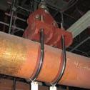
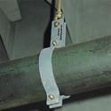


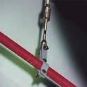
145
146 Pipe clamps, clamp bases, pipe connecting parts Contents Page Field of application Product description Product supplements for pipe clamps and clamp bases Special designs Selection of pipe clamps and clamp bases Selection tables Pipe clamps and clamp bases OD , T 600 C Pipe clamps and clamp bases OD , T 600 C U-bolts Weld-on lugs for pipes Weld-on lugs for pipe elbows Connection plates Lift-off restraints for clamp bases Installation and operating instructions PRODUCT 4 GROUP


147 Field of application In high temperature pipe systems, pipe clamps and clamp bases are the most highly stressed and hence the most vulnerable components in the support chain due to the effects of such high temperatures. However, pipe clamps are seldom checked, as access is difficult after commissioning due to the surrounding insulation. Standardization Pipe clamps, clamp bases, pipe weld-on lugs and U-bolts all fall into the category of pipe connections. For these products, the design criteria of the pipe systems lead to wide variations, and so to a particularly large number of components. The dynamic clamps of product group 3 also belong in principle to this group. The design of both horizontal and vertical piping is determined by: diameters loads temperature of the medium insulation thicknesses For proper coverage of the whole spectrum with safe components, LISG provides a complete program of standardized products for the whole field of application. Following the special requirements of this field, the corresponding ideal design has been developed. the permissible loads divided into economical areas of operation cover the highest level of the practical field of application. Diameters range from OD 21.3 to OD 1219, the temperature range extends to 650 C and 4.1


148 4 These standardized components form an integral part of the LISG modular system, so load and connection compatibility are correspondingly assured. Quality ecause of their critical field of application the design and construction of the pipe-surrounding components require special attention. s a matter of principle, just as much care and attention should be given to the pipe supports as to the piping itself, since the pipe systems can never be better than their supports! The most important prerequisite for reliable component quality is comprehensive standardization. When choosing suitable products the customer should therefore place his confidence in components of proven quality. Plant designers, constructors and operators can all benefit from the standardization of the whole spectrum of application with state-ofthe-art design: complete and clearly structured data tables simplify planning all supplies from a single source through integration into a comprehensive support program (LISG modular system) superior quality at competitive prices through rational series production and technically advanced designs consistent standardization enables short lead times favorable performance / weight ratios, easy-to-install designs and connection compatibility of LISG components allow efficient installation design in accordance with current codes ensures maximum operational safety heat loss reduced through compact component dimensions certifications by independent testing institutes can be supplied for pipe clamps used at higher temperature ranges, materials certified according to N are used 4.2
149 Product description Horizontal clamps Type 41, 42, 43, 44 Type 41 Type Type 43 Type Weld-on lug 41 This is mainly used as a pipe connection for pipe systems under 80 C on horizontal pipes or pipe elbows. 2.1 Horizontal clamp This clamp can be used as a construction clamp or hanger clamp in cold piping systems. The field of application is limited to smaller pipe dimensions. 2.2 Horizontal clamp This clamp is used for larger pipe dimensions. 3 Horizontal clamp 43 This hanger clamp follows the traditional flat steel design. Its use is limited to an economical range up to an individual weight of approximately 25kg. Connection to the load chain is made by pin and LISG threaded eye nuts Horizontal clamp 44 rigid yoke takes up the load from a pipesurrounding U-bolt with a shim plate. From certain diameters, temperatures or load ranges, a flat steel strap is used instead of a round steel U-bolt. Completely eliminating welds, the individual components are form-fitted with plug connections and bolted to each other (Patent No. D ). Horizontal clamp 44 is used where 43 reaches economic limits. These are essentially the high temperature, large pipe diameters in high load ranges. Connection to the load chain is made with a lug and LISG clevis 61. The connection lug is designed to accommodate connection pins in a number of LISG load groups. Type Type The application range of the pipe clamps can extend over several LISG load groups due to the interdependency of load and temperature in material properties. For this, the eye nuts are so designed that at least three corresponding pin diameters can be accommodated. Same function reduced weight Type Pipe clamp 43 weight 27kg U-bolt 44 weight 14kg Weight reduction through 44: Comparison of a LISG pipe clamp with a pipe clamp of traditional shape following the same design criteria, load 32kN, temperature 300 C. 4.3
150 Product description Riser clamps Type 45, 46, Riser clamp 45 With the riser clamp 45 the lower load and temperature ranges are covered. This design is particularly economical for its diameter range. Type 46, for load support using 4 shear lugs welded to the pipe. Two lugs are in general used only for ND 150 and must be so arranged that they are located directly above the side section. Connection to the vertical piping is made with shear lugs welded to the pipe. The design and fitting of the lugs is the responsibility of the piping manufacturer. Connection to the load chain is made with pins and LISG threaded eye nuts 60. t least 3 LISG load groups can be covered. When ordering, the span required (dimension L) must be specified. 2 Riser clamp 46/48 The design of this riser clamp uses the box shape for its economical use of material. The individual parts are connected without welding by means of connections, then locked to each other (Patent No. D ). Connection to the vertically arranged pipe system can be made in two different ways and so requires two different designs: Type 48, for load support using trunnions welded to the pipe. The bore hole diameter for trunnions amounts to approximately 1/3 of the pipe diameter in accordance with SM Code Case N3923 and DIN N Connection to the load chain is done with integrated lugs designed for connection to LISG threaded clevises 61. The connecting lugs are shaped in such a way that they can accommodate the connection pins for several LISG load groups. The inner dimensions of the box, which are required for the later trunnion calculations (N dimension) can, depending on the pipe diameter OD, be taken from the table at the bottom right. Riser clamp 45 with connections Riser clamp 46 with connections Riser clamp 48 with connections Materials of pipe clamps and clamp bases clamp materials S235R S Mo3 13CrMo4-5 21CrMoV5-7 10CrMo9-10 X10CrMoVNb9-1 horizontal clamps 41 x x 42 x x x x x 43 x x x x x 44 x x x x x x x riser clamps 45 x x x x 46 x x x x x 48 x x x x x x clamp bases x x x x x x x x Inner width of box (N-dim.) of riser clamps 46/48 pipe diameter OD 100 OD 100 OD 400 OD 400 N-Dim. OD + 12mm OD + 22mm OD + 32mm 4.4
151 Product description Clamp base Type 49 Clamp bases are generally used as slide bearings (loose supports) for horizontally arranged pipe systems. s with pipe clamps, the application spectrum covers a diameter range from OD 21.3 to OD 1219 and a temperature range up to 600 C; for OD up to 88.9: 650 C. In addition to the support load, the operating temperature of the pipe system is an essential criterion in the design of clamp bases; the material to be used is determined by this. The installation height is governed by the thickness of the insulation. Fixed installation heights are assigned to the temperature ranges in order to keep the number of sizes within a reasonable range. The fixed installation heights relate, for all diameters, to the respective lower rim of the pipe and change by 50mm or 100mm increments. The standard dimensions selected for the support height of the pipes, as well as the length of the slide bases, cover the majority of applications. Different applications, according to temperature and loads, require different clamp base designs. If required, components with special dimensions can be supplied. small selection is shown on page 4.9 in the section Special designs. Possible load applications on a clamp base. µ = friction coefficient material µ steel / steel ~0.3 steel / PTF ~0.1 steel / high temperature component to 280 C steel / high temperature component from 280 C to 350 C ~ ~0.25 Clamp base heights dependent on temperature of the medium and on pipe diameter Further information on page temp. up to 350 C temp. up to 500 C temp. up to 560 C temp. up to 600 C (650 C) H pipe Ø H pipe Ø H pipe Ø H 150 (200) 200 (250) pipe Ø
152 1 Clamp bases for low temperatures and small pipe diameters The design (version 1) for this field of application consists of two omega-shaped halves. On installation with the piping the lower section is firmly bolted and forms the slide base. In the upper section the pipe is held in position by bolting. Through the free space under the pipe gained by the design (version 1) of the component, constant ventilation of this area is ensured. This is essential for cold pipe systems, as otherwise pipe corrosion caused by moisture could result after only a short time. These clamp bases are electro galvanized as a standard. 2 Clamp bases for medium and high temperatures This design (version 2) consists of a shaped lower metal plate, firmly welded to two pipe clamps. The lower section is fitted, according to the respective design load, with a reinforcing gusset. These clamp bases can be used in a variety of ways. y using two lower sections set against each other, a double guide can be easily produced (Fig. 2). y additionally fitting lateral guides, guidance from all sides can be provided. The shape of the base plate permits the simple mounting of lift-off restraints (Fig. 1). The lower section is so designed that it can be fitted with a stainless steel plate as a sliding surface for a slide component. See also product supplements, page Special designs If required, special lengths or heights are possible. For very large expansion displacement it might be more expedient to arrange for correspondingly long support surfaces on site. For special pipe diameters not contained in the selection tables, either corresponding intermediate sizes are supplied, or suitable inlay plates are provided for slight diameter differences. If required, double or multiple guides on the basis of standard clamp bases can be supplied. See also page Version 1: Clamp base for smaller pipe diameters , up to ND150. Version 2: Clamp base for medium and high temperatures , , xamples of use: (Fig. 1) (Fig. 2) Clamp base 49 with lift-off restraint. Permissible loads and dimensions, see page Clamp base G2P as double guide. Clamp base G2 as guide. 4.6


 or the new LISG high temperature sliding material (up to 350 C), reduce friction forces by approx.")
153 Product supplements for pipe clamps and clamp bases Pipe clamps and clamp bases are often equipped with supplementary parts for special applications. For this purpose LISG offers a wide variety of possibilities. 1 Stainless steel inlay plates For the support of austenitic pipe systems, all LISG pipe clamps and clamp bases can be fitted with stainless steel inlay plates of the material (X5CrNi18-10). These plates must be ordered separately and are offered with the following numbers: For series 36: Stainless steel plate IP For series 37: Stainless steel plate IP For series 42: Stainless steel plate IP For series 43: Stainless steel plate IP For series 44: Stainless steel plate IP For series 45: Stainless steel plate IP For series 46/48: Stainl.st.plate 46/ IP For series /12: Stainless steel plate IP For series /14/25/35/45/55: Stainless steel plate 2x IP xamples: For a pipe clamp inlay plate IP. For a clamp base x inlay plate IP. Material thickness: 0.5mm Type 43 with inlay plate Type 44 with inlay plate Stainless steel slide plate under clamp base 49, high temperature slide plate and spring support 29 2 Stainless steel slide plates To reduce friction resistance in clamp bases, all of them can be fitted with stainless steel sliding surfaces of the material (X5CrNi18-10). These sliding surfaces, in combination with PTF slide plates 70 (up to 180 C) or the new LISG high temperature sliding material (up to 350 C), reduce friction forces by approx % of the support load. See also section slide plates page 7.10 This version of the clamp bases with slide plates must be ordered separately. For this, please add the number suffix SP : xamples: SP G2-SP The installation height of the clamp base increases by approximately 3mm. Lift-off restraint 3 Lift-off restraints to The clamp bases can if required be fitted with lift-off restraints. These restraints ensure that the clamp base remains in position if the support load is too small or the clamp base cannot be welded on. They can be ordered according to the selection tables (page 4.68). 4.7


 must be correspondingly selected.")


, pipe guides are offered here as a variant corresponding to")

154 4 Connection plates 77 Two pipe clamps s 43 and 44 can be coupled with connection plates. This way the load can be doubled. selection is shown on page When ordering, this is made clear by replacing the designation of the clamps with 77. xample 43: for clamps for clamps for clamps xample 44: for The load group must be specified for 44, as the upper connection ( 60) must be correspondingly selected. 5 nti-corrosion separating tape Separating tapes are used when the pairing of dissimilar materials in pipe and pipe supports must be electrically separated to prevent local corrosion. This way, the piping can be fitted with supports of more economical martensitic materials, and still be more effectively protected. The adhesive separating tapes can be applied in a temperature range from 35 C to +210 C and are largely resistant to acids, bases and solvents. They are applied as adhesive tape (in part multilayered) to the grease-free piping at the point where the pipe clamp body surrounds the pipe. The material thickness amounts to only 0.5mm. The tapes are supplied in different widths to suit the clamps in whole meter lengths. The order designation is: 6 Pipe guides G.. It is often necessary to limit the piping in its displacement horizontally, vertically or in both directions. On the basis of the 49 standard designs (version 2), pipe guides are offered here as a variant corresponding to the standard design in form and load capacity. The order number is made up from the standard number and the desired features of the design. xample: 49 standard: double guide parallel: G2P 49 lateral guide angulated: G2 49 triple lateral guide: G3 49 foursided guide: G4 These designs can be fitted with extra slide plates. Pipe bearing ( G2P) width [mm] width [mm] b= b= b= b= b= b= b= b= b= b= b= b= b=100 Connection plates 77 on pipe clamps 43/44 Type G2P Type G2 Type G3 4 Order details: nti-corrosion separating tape L = m Type G4 4.8


 larger insulation thicknesses unusual")


155 Special designs For pipe supports, the application of standardized components has long since proven itself through enormous savings in time and costs where design, shipment and installation are concerned. This applies particularly to pipe clamps and clamp bases. However, the general complexity of pipe systems requires an extremely wide range of applications for these components, which in special cases demands the use of special designs. For the technically correct solution it is necessary in such cases to rely on experienced professionals, who can offer triedand-tested solutions and calculation processes. Special designs The standardized LISG program of pipesurrounding support components is comprehensive and covers all general cases of applications, going well beyond the usual spectrum in this field. In spite of this, more complicated cases sometimes occur where only a special design can provide the best solution. mong other things, special designs are most often called for in the following situations: unusually restricted spaces avoidance of interferences custom-made anchors exceptionally high load requirements special pipe diameters especially high temperatures (up to 1000 C) larger insulation thicknesses unusual angles in piping special trunnion diameters twist restraints / shear lugs LISG s customers are not left alone in such situations. For these special problem cases, an experienced team of technicians and engineers is on hand, ready to react rapidly and flexibly with the right solutions. They are backed up by a range of computer software programs developed in-house. On top of this, a broad repertoire of tried-and-tested basic designs is available. There s no problem that can t be solved this conviction is powerful motivation for LISG s experts. We are happy to give our customers proof of this at any time! Special design 40 Special design 48 (seated) Special design 48 for an angulating pipe system Special design 38 Support for a vertical pipe section with special design LISG triple joint (special design) Special design 49 with displacement control
156 Selection of pipe clamps and clamp bases 4 The following points are important for application: 1 ll data needed for determination of the correct component and a clearly defined order are outlined in the selection tables. 2 The connection geometries are compatible with those of the LISG connection components. Due to the wide load application range, connection components from several LISG load groups can be attached. The dimensions and geometries listed in the selection tables can vary slightly as regards design: The permissible loads apply as shown. 3 The lengths of the connecting lugs are so designed that the connection points always lie outside the economical insulation thicknesses. 4 ll pipe clamps and clamp bases can be fitted with corresponding stainless steel inlay plates for use with pipe systems made of austenitic materials. These components can be found on page When selecting a suitable pipe clamp the following sequence is to be followed: 5.1 Determination of the relevant page for the outer diameter (OD) of the pipe system to be supported. The normal pipe tolerances are covered. 5.2 Determination of the relevant temperature range in the column for the desired support, horizontal or vertical. 5.3 Determination of the permissible load to be covered. The permissible operational load taken from the selection table must not be exceeded at any time. The linear interpolation of the permissible load for intermediate temperatures is allowed. 5.4 Checking of installation dimension and width for agreement with the installation conditions on site. The dimensions can be taken from the selection tables. 5.5 Checking of the span width in riser clamps (L DIM.). 5.6 Decision as to whether trunnions or shear lugs are to be used for riser clamps 46/ greement of the connection with the load chain required can be checked via the LISG load group ranges. 5.8 Specify the component selected by entering the relevant LISG number. 6 When selecting a suitable clamp base the points should be followed. ttention must also be paid to selection of the correct height (dimension H) which depends on the thickness of the insulation. 6.1 The heights specified (dimension H) and the lengths (dimension ) are standard dimensions (see selection tables) and cover the most common cases of application. If required, the components can be supplied with different dimensions. 7 Pipe clamps and clamp bases can be supplied as special designs for unusual applications and conditions (see pages 4.6 to 4.9 for this). 8 In the design and construction of LISG pipe clamps and clamp bases, their application in cases of increased requirements was also taken into account. In accordance with the LISG quality management system, separate manufacturing is required for this. The designation thereby changes in the 5 th digit by addition of a 5 (see also pages 0.7 and 0.8 on this). The selection tables on the following pages offer an overview of the fields of application. They are classified in rising stages according to pipe diameters. ll pipe clamps and clamp bases coming into consideration for a planned pipe system can therefore be found on one page. The high-temperature range (600 C 650 C) is included as a supplementary section. The shown loads of the LISG pipe clamps consider a force applied conically below 4. y coupling two pipe clamps with connection plates 77 the loads can be doubled. selection can be found on page
157 Selection table OD 21.3 Temp. of medium 600 C from page 4.52 Load doubling via 77, see page 4.67 Ø d 4 Pipe clamps, clamp bases, OD 21.3 (ND 15), 42, 43, 45, 49 load C d 4 group C-D d1 d C d M C-2 Heat-resistant materials, see pages 0.9 and C d C C C-2 load group load group C d 1 L load group L d C C C C C C C C C C C C C-4 C C C H H H
158 Selection table OD 26.9 Pipe clamps, clamp bases, OD 26.9 (ND 20), 42, 43, 45, 49 Temp. of medium 600 C from page 4.52 Load doubling via 77, see page load C d 4 group C-D Ø d C d 2 load group d M C-2 Heat-resistant materials, see pages 0.9 and C d C C C-2 load group d C d 1 L load group C C C C C C C C C C C C C-4 L d C C H C H H 4.12
159 Selection table OD 33.7 Temp. of medium 600 C from page 4.52 Load doubling via 77, see page 4.67 Ø d 4 Pipe clamps, clamp bases, OD 33.7 (ND 25), 42, 43, 45, 49 load C d 4 group C-D d1 d C d M C-2 Heat-resistant materials, see pages 0.9 and C d C C C-2 load group load group C d 1 L load group L d C C C C C C C C C C C C C C C C C C C C C-4 C H H C C H
160 Selection table OD 42.4 Pipe clamps, clamp bases, OD 42.4 (ND 32), 42, 43, 45, 49 Temp. of medium 600 C from page 4.52 Load doubling via 77, see page load C d 4 group C-D Ø d C d M C-2 Heat-resistant materials, see pages 0.9 and C d C C C-2 load group load group d1 d C d 1 L load group C C C C C-D C-D C-D C-D C C C C L d 1 C H H C C H
161 Selection table OD 48.3 Temp. of medium 600 C from page 4.52 Load doubling via 77, see page 4.67 Ø d 4 Pipe clamps, clamp bases, OD 48.3 (ND 40), 42, 43, 45, 49 load C d 4 group C-D d C d 2 load group M C-2 Heat-resistant materials, see pages 0.9 and C d 1 load group d C C C C d 1 L load group L d 1 C C C C C C-D C-D C-D C-D C C C C H H C C H
162 Selection table OD 60.3 Pipe clamps, clamp bases, OD 60.3 (ND 50), 42, 43, 45, 49 Temp. of medium 600 C from page 4.52 Load doubling via 77, see page load C d 4 group C-D Ø d C d M C-2 Heat-resistant materials, see pages 0.9 and 4.4 load group d C d C C C-4 load group d C d 1 L load group C C C C C-D C-D C-D C-D C C C C H L d 1 C H C C H
163 Selection table OD 73 Temp. of medium 600 C from page 4.52 Load doubling via 77, see page 4.67 Ø d 4 Pipe clamps, clamp bases, OD 73 (ND 65), 42, 43, 45, 46, 48, 49 load C d 4 group C-2 d C d 2 load group M C-2 Heat-resistant materials, see pages 0.9 and 4.4 d C d C C C-4 load group L 46 L d 1 d 3 K C d 1 L C-D C-D C-D C-D load group 48 L 36 d 3 R L load C d 3 min max K [kg min] [kg max] R [kg min] [kg max] group C C C C C H H C C H
164 Selection table OD 76.1 Temp. of medium 600 C from page 4.52 Load doubling via 77, see page 4.67 Pipe clamps, clamp bases, OD 76.1 (ND 65), 42, 43, 45, 46, 48, 49 load C d 4 group C-2 4 Ø d C d 2 load group d M C-2 Heat-resistant materials, see pages 0.9 and C d C C C-4 load group d C d 1 L C-D C-D C-D C-D load group L 46 L d 1 d 3 K 48 L load C d 3 min max K [kg min] [kg max] R [kg min] [kg max] group C C C C L 36 d 3 R C C C H H H 4.18
165 Selection table OD 88.9 Temp. of medium 600 C from page 4.52 Load doubling via 77, see page 4.67 Ø d 4 Pipe clamps, clamp bases, OD 88.9 (ND 80), 42, 43, 45, 46, 48, 49 load C d 4 group C-2 d C d M C-2 Heat-resistant materials, see pages 0.9 and 4.4 load group d C d C-D C-D C-4 load group L 46 L d 1 d 3 K C d 1 L C-D C-D C-D C-D load group 48 L d 3 L load C d 3 min max K [kg min] [kg max] R [kg min] [kg max] group 36 C R C C C C H H C C H
166 Selection table OD 108 Pipe clamps, clamp bases, OD 108 (ND 100), 42, 43, 45, 46, 48, 49 Temp. of medium 600 C from page 4.52 Load doubling via 77, see page C d 2 load group 4 d M Heat-resistant materials, see pages 0.9 and C d C-D C C-D C-D load group d C d 1 L load group L d C-D C-D C-D C-D L d 3 L load C d 3 min max K [kg min] [kg max] R [kg min] [kg max] group C C L 51 K d 3 R C C C H H H 4.20
167 Selection table OD Temp. of medium 600 C from page 4.52 Load doubling via 77, see page 4.67 Pipe clamps, clamp bases, OD (ND 100), 42, 43, 45, 46, 48, 49 d C d 2 load group M Heat-resistant materials, see pages 0.9 and 4.4 d C d C-D C C-D C-D load group L d C d 1 L load group C-D C-D C-D C-D L d 3 48 L 51 K d 3 R L load C d 3 min max K [kg min] [kg max] R [kg min] [kg max] group C C C H H C C H
168 Selection table OD 133 Pipe clamps, clamp bases, OD 133 (ND 125), 42, 43, 45, 46, 48, 49 Temp. of medium 600 C from page 4.52 Load doubling via 77, see page C d 2 load group 4 d M Heat-resistant materials, see pages 0.9 and C d 1 load group C-D C-D C-D C-D d C d 1 L load group L C-D C-D C-D C-D d 1 L d 3 L load C d 3 min max K [kg min] [kg max] R [kg min] [kg max] group C C L K d 3 51 R C C H H H C 4.22
169 Selection table OD Temp. of medium 600 C from page 4.52 Load doubling via 77, see page 4.67 Pipe clamps, clamp bases, OD (ND 125), 42, 43, 45, 46, 48, C d 2 d2 load group M Heat - resistant materials, see pages 0.9 and C d 1 load group d C - D C - D C - D C - D L C d 1 L load group 46 d C - D C - D C - D C - D L d 3 L load C d 3 min max K [kg min] [kg max] R [kg min] [kg max] group C C L K d 3 51 R H H C C C H
170 Selection table OD 159 Pipe clamps, clamp bases, OD 159 (ND 150), 42, 43, 46, 48, 49 Temp. of medium 600 C from page 4.52 Load doubling via 77, see page C d 2 load group 4 d M Heat - resistant materials, see pages 0.9 and C d C - D C - D C - D C - D load group d1 46 L L load C d 3 min max K [kg min] [kg max] R [kg min] [kg max] group C C C L d 3 K d 3 63 R C C H H H C 4.24
171 Selection table OD Temp. of medium 600 C from page 4.52 Load doubling via 77, see page 4.67 Pipe clamps, clamp bases, OD (ND 150), 42, 43, 46, 48, C d 2 d2 load group M Heat - resistant materials, see pages 0.9 and 4.4 d C d C - D C - D C - D C - D load group 46 L 48 L d 3 K d 3 L load C d 3 min max K [kg min] [kg max] R [kg min] [kg max] group C C C R H H C C C H
172 Selection table OD Pipe clamps, clamp bases, OD (ND 175), 42, 43, 46, 48, 49 Temp. of medium 600 C from page 4.52 Load doubling via 77, see page C d 2 load group 4 d M Heat - resistant materials, see pages 0.9 and C d C - D C - D load group d1 L load C d 3 min max K [kg min] [kg max] R [kg min] [kg max] group C C C C L 48 L 63 d 3 K d 3 R C C H C H 4.26
173 Selection table OD Temp. of medium 600 C from page 4.52 Load doubling via 77, see page 4.67 d2 Pipe clamps, clamp bases, OD (ND 200), 42, 43, 44, 46, 48, C d 2 load group M Heat - resistant materials, see pages 0.9 and 4.4 d C d 1 load group C - D C - D d C d 3 load group C C L 48 L 79 d 3 K d 3 R L load C d 3 min max K [kg min] [kg max] R [kg min] [kg max] group C C C C C C H H
174 Selection table OD Pipe clamps, clamp bases, OD (ND 225), 42, 43, 44, 46, 48, 49 Temp. of medium 600 C from page 4.52 Load doubling via 77, see page C d 2 load group 4 d M Heat - resistant materials, see pages 0.9 and C d C - D C - D load group d C d C C load group d3 46 L load C d 3 min max K [kg min] [kg max] R [kg min] [kg max] group L 48 L 79 d 3 K d 3 R C C C H H 4.28
175 Selection table OD 267 Temp. of medium 600 C from page 4.52 Load doubling via 77, see page 4.67 d2 Pipe clamps, clamp bases, OD 267 (ND 250), 42, 43, 44, 46, 48, C d 2 load group M Heat - resistant materials, see pages 0.9 and 4.4 d C d load group d C d C C load group 46 L 48 L 92 d 3 K d 3 R L load C d 3 min max K [kg min] [kg max] R [kg min] [kg max] group C C C H H
176 Selection table OD 273 Pipe clamps, clamp bases, OD 273 (ND 250), 42, 43, 44, 46, 48, 49 Temp. of medium 600 C from page 4.52 Load doubling via 77, see page C d 2 load group 4 d M Heat - resistant materials, see pages 0.9 and C d load group d C d C C load group d3 46 L load C d 3 min max K [kg min] [kg max] R [kg min] [kg max] group L 48 L 92 d 3 K d 3 R C C C H H 4.30
177 Selection table OD Temp. of medium 600 C from page 4.52 Load doubling via 77, see page 4.67 Pipe clamps, clamp bases, OD (ND 300), 42, 43, 44, 46, 48, C d 2 d2 load group M Heat - resistant materials, see pages 0.9 and C d 1 load group d C d 3 load group d L 48 L 118 C d 3 K d 3 R L load C d 3 min max K [kg min] [kg max] R [kg min] [kg max] group C C H H
178 Selection table OD Pipe clamps, clamp bases, OD (ND 350), 42, 43, 44, 46, 48, 49 Temp. of medium 600 C from page 4.52 Load doubling via 77, see page C d 2 load group 4 d M Heat - resistant materials, see pages 0.9 and C d 1 load group d C d 3 load group d3 L load C d 3 min max K [kg min] [kg max] R [kg min] [kg max] group L 48 L 118 C d 3 K d 3 R C C H H 4.32
179 Selection table OD 368 Temp. of medium 600 C from page 4.52 Load doubling via 77, see page 4.67 Pipe clamps, clamp bases, OD 368 (ND 350), 42, 43, 44, 46, 48, C d 2 d2 load group M Heat - resistant materials, see pages 0.9 and C d 1 load group d C d 3 load group d L 48 L 118 C d 3 K d 3 R L load C d 3 min max K [kg min] [kg max] R [kg min] [kg max] group C C H H
180 Selection table OD Pipe clamps, clamp bases, OD (ND 400), 42, 43, 44, 46, 48, 49 Temp. of medium 600 C from page 4.52 Load doubling via 77, see page C d 2 load group 4 d M Heat - resistant materials, see pages 0.9 and C d 1 load group d C d 3 load group d3 L load C d 3 min max K [kg min] [kg max] R [kg min] [kg max] group L 48 L 144 C d 3 K d 3 R C C H H 4.34
181 Selection table OD 419 Temp. of medium 600 C from page 4.52 Load doubling via 77, see page 4.67 Pipe clamps, clamp bases, OD 419 (ND 400), 42, 43, 44, 46, 48, C d 2 d2 load group M Heat - resistant materials, see pages 0.9 and C d 1 load group d C d 3 load group d L 48 L 144 C d 3 K d 3 R L load C d 3 min max K [kg min] [kg max] R [kg min] [kg max] group C C H H
182 Selection table OD Pipe clamps, clamp bases, OD (ND 450), 42, 43, 44, 46, 48, 49 Temp. of medium 600 C from page 4.52 Load doubling via 77, see page C d 2 load group 4 d M Heat - resistant materials, see pages 0.9 and C d 1 load group d C d 3 load group d3 L load C d 3 min max K [kg min] [kg max] R [kg min] [kg max] group L 48 L 144 C d 3 K d 3 R C C H H
183 Selection table OD 508 Temp. of medium 600 C from page 4.52 Load doubling via 77, see page 4.67 Pipe clamps, clamp bases, OD 508 (ND 500), 42, 44, 46, 48, C d 2 d2 load group M Heat - resistant materials, see pages 0.9 and 4.4 d C d 3 load group L 48 L 173 C d 3 K d 3 R L load C d 3 min max K [kg min] [kg max] R [kg min] [kg max] group H C C H
184 Selection table OD Pipe clamps, clamp bases, OD (ND 550), 42, 44, 46, 48, 49 Temp. of medium 600 C from page 4.52 Load doubling via 77, see page C d 2 load group 4 d M Heat - resistant materials, see pages 0.9 and C d 3 load group d3 L load C d 3 min max K [kg min] [kg max] R [kg min] [kg max] group L 48 L 173 C d 3 K d 3 R C C H H 4.38
185 Selection table OD Temp. of medium 600 C from page 4.52 Load doubling via 77, see page 4.67 Pipe clamps, clamp bases, OD (ND 600), 42, 44, 46, 48, 49 d C d 2 load group M Heat - resistant materials, see pages 0.9 and 4.4 d C d 3 load group L 48 L 199 C d 3 K d 3 R L load C d 3 min max K [kg min] [kg max] R [kg min] [kg max] group H C C H
186 Selection table OD Temp. of medium 600 C from page 4.52 Load doubling via 77, see page 4.67 Pipe clamps, clamp bases, OD (ND 650), 42, 44, 46, 48, 49 load C d 2 group M d C d 3 load group Heat-resistant materials, see pages 0.9 and 4.4 d3 L load C d 3 min max K [kg min] [kg max] R [kg min] [kg max] group L 48 L 224 C d 3 K d 3 R C C H H 4.40
187 Selection table OD Temp. of medium 600 C from page 4.52 Load doubling via 77, see page 4.67 d2 Pipe clamps, clamp bases, OD (ND 700), 42, 44, 46, 48, 49 load C d 2 group M Heat-resistant materials, see pages 0.9 and 4.4 d C d 3 load group L 48 L 224 C d 3 K d 3 R L load C d 3 min max K [kg min] [kg max] R [kg min] [kg max] group H C C H
188 Selection table OD 762 Temp. of medium 600 C from page 4.52 Load doubling via 77, see page 4.67 Pipe clamps, clamp bases, OD 762 (ND 750), 42, 44, 46, 48, 49 load C d 2 group M d C d 3 load group Heat-resistant materials, see pages 0.9 and 4.4 d3 L load C d 3 min max K [kg min] [kg max] R [kg min] [kg max] group C C H L 48 H L 250 C d 3 K d 3 R 4.42
189 Selection table OD Temp. of medium 600 C from page 4.52 Load doubling via 77, see page 4.67 d2 Pipe clamps, clamp bases, OD (ND 800), 42, 44, 46, 48, 49 load C d 2 group M Heat-resistant materials, see pages 0.9 and 4.4 d C d 3 load group L 48 L 250 C d 3 K d 3 R L load C d 3 min max K [kg min] [kg max] R [kg min] [kg max] group H C C H
190 Selection table OD Temp. of medium 600 C from page 4.52 Load doubling via 77, see page 4.67 Pipe clamps, clamp bases, OD (ND 850), 42, 44, 46, 48, 49 load C d 2 group M d C d 3 load group Heat-resistant materials, see pages 0.9 and 4.4 d3 L load C d 3 min max K [kg min] [kg max] R [kg min] [kg max] group L 48 L 279 C d 3 K d 3 R C C H H 4.44
191 Selection table OD Temp. of medium 600 C from page 4.52 Load doubling via 77, see page 4.67 d2 Pipe clamps, clamp bases, OD (ND 900), 42, 44, 46, 48, 49 load C d 2 group M Heat-resistant materials, see pages 0.9 and 4.4 d C d 3 load group L 48 L 279 C d 3 K d 3 R L load C d 3 min max K [kg min] [kg max] R [kg min] [kg max] group H C C H
192 Selection table OD Temp. of medium 600 C from page 4.52 Load doubling via 77, see page 4.67 Pipe clamps, clamp bases, OD (ND 950), 42, 44, 46, 48, 49 load C d 2 group M d C d 3 load group Heat-resistant materials, see pages 0.9 and 4.4 d3 L load C d 3 min max K [kg min] [kg max] R [kg min] [kg max] group C C H L 48 H L 330 C d 3 K d 3 R 4.46
193 Selection table OD 1016 Temp. of medium 600 C from page 4.52 Load doubling via 77, see page 4.67 d2 Pipe clamps, clamp bases, OD 1016 (ND 1000), 42, 44, 46, 48, 49 load C d 2 group 42 T M Heat-resistant materials, see pages 0.9 and 4.4 d C d 3 load group 44 T T T T T T T T T T T T T T T T T T T T L 48 H L 330 C d 3 K d 3 R L load C d 3 min max K [kg min] [kg max] R [kg min] [kg max] group 4. T T T T T T T T T T T T T T T T T T T T T T T T T T C C H 49 T T T T T
194 Selection table OD 1067 Temp. of medium 600 C from page 4.52 Load doubling via 77, see page 4.67 Pipe clamps, clamp bases, OD 1067 (ND 1050), 42, 44, 46, 48, 49 load C d 2 group 42 T M d C d 3 load group 44 T T T T T T T T T T T T T T T T T T T T Heat-resistant materials, see pages 0.9 and 4.4 d3 L load C d 3 min max K [kg min] [kg max] R [kg min] [kg max] group 4. T T T T T T T T T T T T T T T T T T T T T T T T T T C C H 49 T T T T T L 48 H L 330 C d 3 K d 3 R 4.48
195 Selection table OD 1118 Temp. of medium 600 C from page 4.52 Load doubling via 77, see page 4.67 d2 Pipe clamps, clamp bases, OD 1118 (ND 1100), 42, 44, 46, 48, 49 load C d 2 group 42 T M Heat-resistant materials, see pages 0.9 and 4.4 d C d 3 load group 44 T T T T T T T T T T T T T T T T T T T T L 48 H L 374 C d 3 K d 3 R L load C d 3 min max K [kg min] [kg max] R [kg min] [kg max] group 4. T T T T T T T T T T T T T T T T T T T T T T T T T T C C H 49 T T T T T
196 Selection table OD 1168 Temp. of medium 600 C from page 4.52 Load doubling via 77, see page 4.67 Pipe clamps, clamp bases, OD 1168 (ND 1150), 42, 44, 46, 48, 49 load C d 2 group 42 T M d C d 3 load group 44 T T T T T T T T T T T T T T T T T T T T Heat-resistant materials, see pages 0.9 and 4.4 d3 L load C d 3 min max K [kg min] [kg max] R [kg min] [kg max] group 4. T T T T T T T T T T T T T T T T T T T T T T T T T T L 48 L 374 C d 3 K d 3 R C C H 49 T T T T T H 4.50
197 Selection table OD 1219 Temp. of medium 600 C from page 4.52 Load doubling via 77, see page 4.67 d2 Pipe clamps, clamp bases, OD 1219 (ND 1200), 42, 44, 46, 48, 49 load C d 2 group 42 T M Heat-resistant materials, see pages 0.9 and 4.4 d C d 3 load group 44 T T T T T T T T T T T T T T T T T T T T L 48 L 374 C d 3 K d 3 R L load C d 3 min max K [kg min] [kg max] R [kg min] [kg max] group 4. T T T T T T T T T T T T T T T T T T T T T T T T T T H C C H 49 T T T T T
198 Selection table OD Temperatures C Pipe clamps, clamp bases, OD 21.3 (ND 15), 45, C d 1 L load group C C C C C C H Pipe clamps, clamp bases, OD 26.9 (ND 20), 45, 49 load C d 1 L group C C C C C C H d1 Pipe clamps, clamp bases, OD 33.7 (ND 25), 43, 45, 49 load C d 1 group C - 2 load C d 1 L group C C C C C C C C C C H Pipe clamps, clamp bases, OD 42.4 (ND 32), 43, 45, 49 load C d 1 group C - 2 load C d 1 L group C C C C C C H H 45 L d 1 49 C 4.52
199 Selection table OD Temperatures C Pipe clamps, clamp bases, OD 48.3 (ND 40), 43, 45, 49 load C d 1 group C d1 45 load C d 1 L group C C C C C C H L d 1 48 L d N d 3 R Pipe clamps, clamp bases, OD 60.3 (ND 50), 43, 45, 49 load C d 1 group C - 4 load C d 1 L group C C C C C C H H C Pipe clamps, clamp bases, OD 73 (ND 65), 43, 48, 49 load C d 1 group C - 4 L load C d 3 d N R min max min max group C C C C H
200 Selection table OD Temperatures C Pipe clamps, clamp bases, OD 76.1 (ND 65), 43, 48, 49 load C d 1 group C - 4 L load C d 3 d N R min max min max group C C C C H Pipe clamps, clamp bases, OD 88.9 (ND 80), 43, 48, 49 load C d 1 group C - 4 L load C d 3 d N R min max min max group C C C C H Pipe clamps, OD 108 (ND 100), 43, 48 load C d 1 group L load C d 3 d N R min max min max group C Pipe clamps, OD (ND 100), 43, 48 load C d 1 group L load C d 3 d N R min max min max group C d C L d 3 d N R Pipe clamps, OD 133 (ND 125), 43, 48 load C d 1 group H L load C d 3 d N R min max min max group C
201 Selection table OD Temperatures C Pipe clamps, OD (ND 125), 43, 48 load C d 1 group d1 L load C d 3 d N R min max min max group C Pipe clamps, OD 159 (ND 150), 43, 48 load C d 1 group d 3 L load C d 3 d N R min max min max group C Pipe clamps, OD (ND 150), 43, 48 load C d 1 group L load C d 3 dn R min max min max group C Pipe clamps, OD (ND 175), 43, 48 load C d 1 group L d 3 L load C d 3 d N R min max min max group C d N R Pipe clamps, OD (ND 200), 44, 48 max max load C d 3 insul. group C L load C d 3 d N R min max min max group C
202 Selection table OD Temperatures C Pipe clamps, OD (ND 225), 44, 48 max max load C d 3 insul. group C L load C d 3 d N R min max min max group Pipe clamps, OD 267 (ND 250), 44, 48 max max load C d 3 insul. group C d 3 L load C d 3 d N R min max min max group Pipe clamps, OD 273 (ND 250), 44, 48 max max load C d 3 insul. group C L load C d 3 d N R min max min max group L d N d 3 R Pipe clamps, OD (ND 300), 44, 48 max max load C d 3 insul. group L load C d 3 d N R min max min max group
203 Selection table OD Temperatures C Pipe clamps, OD (ND 350), 44, 48 max max load C d 3 insul. group L load C d 3 d N R min max min max group d 3 Pipe clamps, OD 368 (ND 350), 44, 48 max max load C d 3 insul. group L L load C d 3 d N R min max min max group d N d 3 R Pipe clamps, OD (ND 400), 44, 48 max max load C d 3 insul. group L load C d 3 d N R min max min max group
204 Selection table OD Temperatures C Pipe clamps, OD 419 (ND 400), 44, 48 max max load C d 3 insul. group L load C d 3 d N R min max min max group Pipe clamps, OD (ND 450), 44, 48 max max load C d 3 insul. group d 3 L load C d 3 d N R min max min max group L d 3 Pipe clamps, OD 508 (ND 500), 44, 48 max max load C d 3 insul. group L load C d 3 d N R min max min max group d N R 4.58
205 Selection table OD Temperatures C Pipe clamps, OD (ND 550), 44, 48 max max load C d 3 insul. group d 3 L load C d 3 d N R min max min max group Pipe clamps, OD (ND 600), 44, 48 max max load C d 3 insul. group L d 3 L load C d 3 d N R min max min max group d N R Pipe clamps, OD (ND 650), 44, 48 max max load C d 3 insul. group L load C d 3 d N R min max min max group
206 Selection table OD Temperatures C Pipe clamps, OD (ND 700), 44, 48 max max load C d 3 insul. group L load C d 3 d N R min max min max group Pipe clamps, OD 762 (ND 750), 44, 48 max max load C d 3 insul. group d 3 L load C d 3 d N R min max min max group Pipe clamps, OD (ND 800), 44, 48 max max load C d 3 insul. group L load C d 3 d N R min max min max group L d N d 3 R 4.60
207 Selection table OD Temperatures C Pipe clamps, OD (ND 850), 44, 48 max max load C d 3 insul. group d 3 L load C d 3 d N R min max min max group Pipe clamps, OD (ND 900), 44, 48 max max load C d 3 insul. group L d N d 3 R L load C d 3 d N R min max min max group Pipe clamps, OD (ND 950), 44, 48 max max load C d 3 insul. group L load C d 3 d N R min max min max group
208 Selection table OD Temperatures C Pipe clamps, OD 1016 (ND 1000), 44, 48 max max load C d 3 insul. group 44 T T T T T T T L load C d 3 d N R min max min max group 48 T T T T T T T Pipe clamps, OD 1067 (ND 1050), 44, 48 max max load C d 3 insul. group 44 T T T T T T T d 3 L load C d 3 d N R min max min max group 48 T T T T T T T Pipe clamps, OD 1118 (ND 1100), 44, 48 max max load C d 3 insul. group 44 T T T T T T T L load C d 3 d N R min max min max group 48 T T T T T T T L d N d 3 R 4.62
209 Selection table OD Temperatures C Pipe clamps, OD 1168 (ND 1150), 44, 48 max max load C d 3 insul. group 44 T T T T T T T d 3 L load C d 3 d N R min max min max group 48 T T T T T T T Pipe clamps, OD 1219 (ND 1200), 44, 48 max max load C d 3 insul. group 44 T T T T T T T L d N d 3 R L load C d 3 d N R min max min max group 48 T T T T T T T


210 U-bolts Type 40 4 U-bolts to OD Type 40 mainly serves to fasten pipe systems to existing steel structures. L Ø d 2 OD d 2 x L weight M6 x M6 x M6 x M10 x M10 x M10 x M12 x M12 x M12 x M12 x M12 x M12 x M16 x M16 x M20 x M20 x M20 x M20 x M24 x M24 x M24 x M24 x M24 x M24 x M24 x M24 x M24 x M24 x th digit: 1 = carbon steel 3 = stainless steel Order details: U-bolt Scope of delivery: incl. 4 nuts 4.64
211 Weld-on lugs for pipes Type 41 Weld-on lugs for pipes 41 D9 11 to t Permissible load at 80 C = normal operating conditions (load case H / level /) of the corresponding load group (3 rd digit in the designation, see Max. permissible load for static components, page 0.6). H C G Ø d 3 R xisting stress in the specified weld seam 50 N/mm 2 at 4 load angle. OD s max Material: carbon steel s max = 10mm s max = 100mm Ø d 3 H R C G t a weight 41 D D Reduction factors of permissible load at increased temperatures: T F perm. (T) 250 C 0.7 F perm. (80 C) 350 C 0.5 F perm. (80 C) Order details: weld-on lug for pipes
212 Weld-on lugs for pipe elbows Type 41 S max = 10mm weight a S max = 100mm weight a Permissible loads at 80 C = normal operating conditions (load case H / level /) of the specified load group in each case (see Max. permissible load for static components, page 0.6). load OD group C R 1 t d C C C C C C C C C Stress existing in the specified weld seam 50 N/mm 2 at 4 load angle. 4 Weld-on lugs for pipe elbows (R 1.5 OD) to Material: carbon steel C s max t Ø d 3 R Reduction factors of permissible load at increased temperatures: T F perm. (T) 250 C 0.7 F perm. (80 C) 350 C 0.5 F perm. (80 C) Order details: weld-on lug for pipe elbows R 1.5 OD R OD s max =10mm s max =100mm 4.66
213 Connection plates Type 77 Connection plates for coupling pipe clamps 43 d to y coupling 2 pipe clamps with 77 the loads can be doubled. Order details: connection plate for clamps load group up to D up to up to d 3 weight Connection plates for coupling pipe clamp 44 up to 600 C d to 77 T4.. Type designation of the connection plates: the figures 44 of the clamps to be coupled must be replaced by the figures 77. xample: connection plate for load group d 1 min max max weight up to up to up to up to up to up to 77 T The load group for the upper connection ( 60) must be stated when ordering. Order details: connection plate load group


214 Lift-off restraints for clamp bases Type 49 4 Lift-off restraints for clamp base to F Z t Material: plate t 15mm : S235R plate t 20mm : S3552 C H F X for clamp bases C H t max load F X [kn] /pair up to up to up to up to up to up to up to up to up to up to up to up to up to up to 49 T The following short duration lift-off loads are permissible for the clamp bases: to % to 49 T4.. 7% of the catalog load. When used as a guide it must be ensured that the pipe supports are secured against rotation about the pipe axis. F X is the max. lateral load at a weld seam stress of 50 N/mm 2 in the load case H (level /). Simultaneous lift-off loads are taken into consideration. On request special lift-off restraints for SP can be delivered. Order details: lift-off restraint
215 Installation and operating instructions Type 42, 43, 44, 45, 46, 48 Type Type Type 43 Type 44 U-bolt design 1 Transport and storage Care must be taken during transport that none of the clamp components are damaged. When stored in the open the clamps must be protected from dirt and water. 2 Delivery condition LISG pipe clamps are delivered ready for installation, with all the necessary bolts. For reason of more optimize dispatch clamps can be supplied partially assembled. 3 Installation 3.1 Horizontal clamp Type 42 This clamp is used as a horizontal clamp in connection with threaded eye nut 60. When tightening the bolts, care must be taken that the clamp halves are parallel to each other. The bolts are to be secured with lock nuts. Type 43 Connection is made with this horizontal clamp via a separate connection pin with a threaded eye nut 60. The pins must be secured with the cotter pins provided; otherwise proceed as with 42. Type 44 U-bolt/ strap for temperatures up to 600 C These clamps consist of an upper section with a connecting lug and, depending on load and temperature range, a U-bolt with an inlay plate or a flat steel strap as lower section. For installation, remove the pre-assembled lower part by loosening the locking nuts or removing the connection pins. The upper section is seated on the piping and the lower one inserted and held by bolting the U-bolt or gib the flat steel strap. fter alignment of the clamp the bolts are to be firmly tightened. The U-bolts are secured with lock nuts and the flat steel straps with tab washers under the hexagon nuts. Type 44 for temperatures over 600 C These clamps consist of an upper section with a connection lug and restrainer and a flat steel strap as lower part. For installation the restraint and strap must be taken off by removing the outer threaded rods and the connection pins. fter attaching the upper section to the hanging part the restraint and strap can be reconnected. fterwards they are pinned and the threaded rods are fitted. ll parts must then be firmly secured. Installation of 44 for temperatures over 600 C 3.2 Riser clamps Type 45 When installing these clamps care must be taken to place the spacers supplied onto the bolts between the clamp halves. The bolts are then tightened and locked. The clamp is hung up via the outer support pins, which are secured with washers and cotter pins. The specified height of the clamp is set by tightening the suspended parts and creating a force-and form-fitting connection with the shear lugs. Riser clamp 45 with connection components Type 44 strap design 4.69
216 Type 46 This riser clamp is supplied in single parts sealed in plastic shrink wrap. For installation it is best to first fit the front plates into the suspended parts. These parts should be tightened at the lowest level, then both side plates can be attached one after another. In the case of large clamps, the opp o site side must hereby be temporarily propped up. For installation, both side plates are seated on the trunnions and connected with the threaded rods. The nuts should be only loosely tightened here. For large clamps the components should be temporarily propped up. The front plates can now be pushed from below into the intake slots and connected to the suspended parts. The connection points between front and side plates are made by aligning and firmly tightening the pre-assembled locking plates. The specified height of the clamp is set by tightening the suspended parts, creating a force- and form-fitting connection with the trunnions. Riser clamp 46 with connection components 4 Riser clamp 48 with connection components Type 46 Type 48 fter that, the top plates for the shear lugs are inserted and bolted on. The connection points between front and side plates are secured by aligning and firmly tightening the pre-assembled locking plates. The specified height is set by tightening the suspended parts, creating a force- and formfitting connection with the shear lugs. 4 Inspection and maintenance The horizontal clamp functions flawlessly in any operating condition if the secured boltings are free of any play. Under normal operating conditions maintenance is not required. Type 48 This riser clamp is supplied in single parts sealed in shrink wrap. First of all, a side plate should be prepared by attaching the thread ed rods. 4.70


217 Installation and operating instructions Type 49 Clamp bases for smaller pipe diameters , up to ND150 Clamp bases for medium and high temperatures , , Transport and storage Care must be taken during transport that no clamp base components are damaged. When stored in the open, the clamp bases must be protected from dirt and water. 2 Delivery condition If not agreed otherwise, LISG clamp bases are delivered pre-assembled and ready for installation. For reasons of efficient dispatch clamp bases can be delivered partially assembled. In any event the clamp base is supplied with all the necessary bolts. 3 Installation Type 49 LISG clamp bases are slidable supports that are fastened to pipe systems by clamping tension. On installation it is essential that the whole clamp base bottom lies flush and can slide unobstructed over the given stretches. If required, the lower parts can be welded to the supporting surface. Different designs are used depending on the height of the support, the pipe diameter, the support load and the operating temperature. The following points are hereby to be observed: 4 Inspection and maintenance Under normal circumstances no maintenance is required. Type and Type and Clamp base 49 with slide plate Type and This clamp base design is made up of two halves to be fitted to each side of the pipe. The cornered surfaces form the base. In this lower part the clamp base halves are firmly bolted to each other. The upper bolting serves for clamping tension in the piping against slipping. Type , and The base part of the clamp base forms a firm support for the pipe to be laid in. The upper half provides clamping tension and is to be firmly bolted. Type , and
218 Roller bearings, pipe saddles, cryogenic clamp bases 5 cryogenic Roller bearings, pipe saddles, clamp bases PRODUCT 5 GROUP

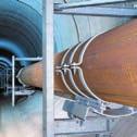

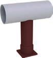
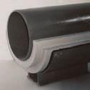
219
220 Roller bearings, pipe saddles, cryogenic clamp bases Contents Page Roller bearings and pipe saddles Selection tables Cylinder roller bearings Double taper roller bearings Double cylinder roller bearings Weld-on pipe saddles Pipe saddles with clamps Pipe trays with clamps Lift-off restraints Cryogenic pipe supports HIPC 56, Selection tables Weld-on pipe shoes Stanchions Stanchions for horizontal pipes Stanchions for short radius elbows (R P OD) Stanchions for long radius elbows (R P 1.5 OD) PRODUCT 5 GROUP

221 Roller bearings and pipe saddles Type 51, 52, 53, 54, 55 Pipe systems arranged horizontally over longer stretches are supported by movable support bearings and fixed points. To ensure thermal expansion displacement with little friction, the bearing points are designed to be rolling or sliding. For pipe systems of larger diameters and especially where high loads are caused by fluids and insulation weights, the optimum solution is provided by roller bearings of high load-bearing capacity, great reliability and extremely low friction resistance. LISG standard roller bearings and pipe saddles These components offer a suitable standard solution for a wide range of applications within product group 5. For use outside the standard range specially modified designs can be supplied. Design features and execution In the development of standard roller bearings, the particular practical requirements that had to be met, were taken into account. The design of the roller bearing enables optimum corrosion protection through hot dip galvanization. The bearing axles are made of austenitic material with polished surfaces. s bearings for the rollers, bushings made of a sintered teflon / bronze composite material are fitted. They are maintenance-free and guarantee smooth dry run characteristics. formed collar on the bushings minimizes starting friction on lateral loading. The bearing axles are permanently fixed in the middle section of the base body of the double cylinder roller bearings. Special securing devices on the side bracket are not required. The rollers are of high-tensile carbon steel. The running surfaces are machined. To balance lateral offset in anchor bolts on site, the intake holes of the base body are slotted. The installation height ( dimensions) within a load group range are the same for rigid and laterally movable roller bearings. Data on material quality, norms, calculations and welding can be found in the technical specifications, pages 0.9 and Manufacture and storage Standardization of the products permits efficient series production and storage for most components. For individual manufacture or fabrication in small batches, modern order logistics ensures rapid production and delivery. Technical data for roller bearings: rolling resistance of the rollers max. 4% rolling resistance on lateral displacement max. 4% temperature range for nominal load 30 C to + 80 C permissible lateral loading 35% of nominal load permissible lift-off load 10% of nominal load 5.1 Special pipe saddle 54 with double cylinder roller bearing 53 and lift-off restraints 55

222 Their special design and their manufacturing quality offer the following benefits in application: 5 Roller bearings The roller bearings can be fastened with simple bolted connections or welded to the supporting surface. In all cases the whole base plate must lie flush on the surface. On slight lateral offset of existing anchor bolts the roller bearings can be easily aligned using the existing slot holes. Pipe saddles Pipe saddles for welding are supplied with a weldable primer as corrosion protection (see technical specifications, pages 0.10 and 0.11). Clamp-fastened pipe saddles are supplied ready-to-install. Close attention must be paid to true-to-size seating and sufficient prestressing. Lift-off restraints When installing lift-off restraints, normal displacement over the whole range must be ensured to allow sufficient play between rollers and lift-off restraints. maintenance of minimum rolling resistance (max. 4%) absorption of realistic lateral loading for double taper and double cylinder roller bearings (35% of the support load) for double cylinder roller bearings the whole support load can be carried by a single roller absorption of lateral displacement possible by laterally movable designs safe and simple design of lift-off restraints pipe saddles facilitate load transmission into the pipe walls pipe saddle design minimizes heat transmission hot dip galvanized corrosion protection for all roller bearings maintenance-free operation roller axle made of non-rusting steel teflon-bronze composite bushings wide range of support diameters (OD 60mm OD 1350mm) high load capacity (max. support load 120kN) low installation heights (see selection table for dimensions) 5.2
223 Roller bearings Type 51, 52 Cylinder roller bearings to Surface: hot dip galvanized 2 1 F a s G b Order details: cylinder roller bearing load F N [kn] 1 2 F G a b s weight Double taper roller bearings to Surface: hot dip galvanized R F a s x C G b a = x R + x Order details: double taper roller bearing load F N [kn] R C a min. max. F G a b s x weight Double taper roller bearings (laterally movable) to Surface: hot dip galvanized travel 50mm R a a F s x C G b a a = x R + x Order details: double taper roller bearing (laterally movable) load F N [kn] R C a min. max. F G a b s x weight
![Double cylinder roller bearings Type 53 5 R s a Double cylinder rollers bearing 53 08 19 to 53 12 19 C x Surface: hot dip galvanized 2 b G a F 1 load F N [kn] R 1 2 C a](/docs-images/93/114255555/images/224-0.jpg "min. max. F G a b s x 53 08 19 8 30 190 210 190 80 65 72 242 140 60 20 10 5 40 2.5 53 16 19 16 85 310 310 285 100 90 135 375 230 75 24 12 6 45 5.")


224 Double cylinder roller bearings Type 53 5 R s a Double cylinder rollers bearing to C x Surface: hot dip galvanized 2 b G a F 1 load F N [kn] R 1 2 C a min. max. F G a b s x weight a = x R + x Order details: double cylinder roller bearing Double cylinder roller bearings (laterally movable) to R travel s = lateral pipe movement a K Surface: hot dip galvanized x H c t Ø d C + travel s b F G weight load F N [kn] R C Ød a min. max. F G H K t x for s = 100mm + per 100mm a = x R + x b Travel s = mm. c Middle fixed point from travel s = 300mm. Order details: double cylinder roller bearing (laterally movable) with s = mm 5.4

![. 19 R = mm Pipe saddles with clamps 54 06 29 to 54 81 29 s s load F N [kn] a OD R b s L=300 weight 54 06 19 1.4 60.3 80 180 3.0 3 1.4 3.5 54 08 19 1.4 76.1 90 190 3.0 3 1.5 3.7 54 09 19 1.4 88.](/docs-images/93/114255555/images/225-2.jpg "9 95 195 3.0 3 1.5 3.8 54 11 19 1.8 114.3 110 210 3.0 3 1.5 4.0 54 14 19 4.0 139.7 120 220 3.0 4 2.0 5.0 54 17 19 4.0 168.3 135 235 3.0 5 3.0 6.5 54 19 19 5.0 193.7 150 250 3.0 5 3.0 6.8 54 22 19 8.")
225 Weld-on pipe saddles Type 54 Pipe saddles with clamps Type 54 Weld-on pipe saddles to Material: plate s 15mm: S235R plate s 20mm: S3552 up to OD R OD b from OD R OD b Surface: weldable primer a Load at pipe temperature m 150 C b Minimum weld seam Order details: weld-on pipe saddle R = mm Pipe saddles with clamps to s s load F N [kn] a OD R b s L=300 weight Surface: hot dip galvanized up to OD R OD from OD R OD s s L=300 a Load at pipe temperature m 150 C Order details: pipe saddle with clamps R = mm load F N [kn] a OD R s weight
226 R Pipe trays with clamps Type 54 Lift-off restraints Type 55 5 Pipe trays with clamps to OD Surface: hot dip galvanized s 90 L=300 load F N [kn] OD R s weight Order details: pipe tray with clamps R OD Lift-off restraints to Surface: hot dip galvanized L=300 compatible with roller bearing, R Order details: lift-off restraint for special pipe saddles R = mm 5.6


227 Cryogenic pipe supports HIPC Type 56, 57 Warehouse for moulded insulations Preassembled insulated supports Special design for Ø mm insulation thickness [mm] insulation level thickness [mm] / / / 40 / / 50 / / 80 / / 100 / / 100 / 75 Supports for cold and cryogenic applications LISG offers a complete product program of insulated pipe supports for all kinds of low temperature pipe systems. These products are normally used in industrial processes for the production, transport and distribution of liquefied gases. These can be propane and butane (LPG), methane (LNG), ethylene, nitrogen, ammonia etc.. LISG insulated pipe supports are standardized and designed according to recognized international technical codes and standards. They cover pipe sizes ranging from OD 21.3mm to OD 965.2mm, with insulation thicknesses from 25mm to 250mm. The supports are made from materials suitable for the specified loads and temperatures (temperature of medium as low as -196 C). Insulating material The material of the insulated standard pipe supports is made from fire-retarding polyurethane foam of high density (HD-PUF) and forms an integral part of the piping insulation. Production of HD-PUF insulation The HD-PUF insulation is molded in heavy duty molds under carefully controlled conditions in respect of temperature and air humidity. This process ensures dimensional stability as well as clean sharp edges that fit neatly with the adjacent line insulation material on site. To guarantee form stability, the molds are stored for a fixed period of time in order to cure. For insulations of higher thicknesses stepped joints are provided to match the layering of the adjoining line insulation. This method, also known as shiplapping, provides a reliable interlocking connection to each layer and prevents a direct heat path from the surface of the insulation through to the surface of the piping. The stepped joints are 25mm long but can be supplied in 50mm steps on request. Insulation foam with thicknesses up to 50mm are single-layer designs without stepping. Insulation foam with thicknesses of 80mm to 100mm are single layer with an extended step at either side. For 56, insulation foam thicknesses of 130mm and higher are supplied as double-layer with two steps. To achieve load transmission for axial stop 57, the HD-PUF insulation is designed as single-layers. oth single-layer and double-layer HD-PUF insulation have stepped longitudinal joints. The size of these joints must be adjusted during installation to a specified gap dimension to ensure a clamping force from the insulated, pipe support on the piping. Once installed the longitudinal gaps are then filled with a flexible insulating foam. The clamping force, which is applied by means of disc spring bolting, prevents relative movement between pipe support and piping. laminated aluminum/polyester vapor barrier is factory-bonded to the outer surface of the HD-PUF insulation. The vapor barrier overlaps the longitudinal joints and is sealed at site with a special vapor barrier adhesive tape. Directly after installation of the insulated pipe support, all exposed HD-PUF surfaces must be protected from moisture. For this purpose a cryogenic, elastomeric coating is applied as vapor barrier. For the HD-PUF insulation three standard color-coded densities for various load requirements are available. 160kg/m 3 yellow 224kg/m 3 red 320kg/m 3 green 5.7


228 Special advantages of HIPC insulated pipe supports 5 a c b e d a HD-PUF insulation with stepped long - itudinal joints and stepped front ends b steel cradle c metal protective shield d disc spring bolting e vapor barrier Finite element analysis of a special design Insulated pipe support base LISG standardized insulated pipe supports are designed to be clamped mechanically to the piping by means of disc spring bolting. The pipe support steel cradle, which houses the HD-PUF insulation, is made of carbon steel and hot-dip galvanized as standard. Material grades, welding and surface treatment comply with the LISG standard specifications. The integrated LISG quality assurance system applies to both the manufacture and preassembly of the pipe supports. Inspection and testing procedures guarantee compliance with the required specifications. LISG insulated standard pipe supports are supplied with detailed installation instructions. very support is clearly marked according to the LISG designation system. The flexible gap filler insulation foam, as well as the special vapor barrier sealing tape are part of the scope of supply. dditional site installation materials such as cryogenic adhesives and mastics can be supplied on request. LISG insulated pipe supports are completely preassembled and supplied in appropriate packaging to protect them from surface damage and humidity during transport and storage. Insulated standard pipe support 57 Preassembled insulated pipe supports 5.8


 is possible.")


 G2P: Double clamp base pipe support (parallely")
229 Type Type G2 Type G2P Design Type 56 is a conventional insulated pipe support and functions as a slide or guide support. Type 57 is similar to 56 but serves as an axial stop that absorbs increased axial loads by means of thrust rings. The thrust rings on the piping consist of two half-rings which are welded together at site to form a single ring. The rings, which are movable on the piping, are fixed by means of shear lugs welded onto the pipe. This patented design offers the advantage of fixing the insulated pipe support to the piping after final positioning. There is no need to disassemble any existing or already installed steelwork. The thrust rings and shear lugs are made of stainless steel and form part of the scope of supply. Double and multiple clamp base pipe supports For high vertical loads or high lateral loads, double clamp bases or guided supports are required. For this purpose, LISG s insulated pipe sup ports can be extended as required. ach variant is given a suffix after the 6 th digit which describes the of guide used. The pipe support can be ordered in the following designs: Special design LISG takes pride in offering solutions to their clients and will gladly assist in any special inquiry. Special pipe sizes can be accommodated. For large axial movements, special lengths can be supplied. The use of an insulated pipe support as a hanger (e.g. in combination with spring or constant hangers) is possible. In this case the shoe of the clamp base is replaced by a special pipe clamp 43. The clamp is then designed for the particular conditions existing in each case. Deviations from the standard HD-PUF densities can be supplied, e.g. a density of 500kg/m 3 for high loads. The use of the pipe support on sliding components is possible. For this purpose a stainless steel plate is fixed to the underside of the shoe. Type G3 For special applications when increased loads have to be absorbed, laminated wooden blocks can be utilized. Type G4 Insulated double clamp base G2P G2: ngulated clamp base pipe support (laterally guided) G2P: Double clamp base pipe support (parallely guided) G3: Triple clamp base pipe support G4: Quadruple clamp base pipe support Type 56 as well as 57 can be ordered with these guide options. 57 can be used e.g. as a quadruple pipe support in a vertical pipe. The installation dimension can be adjusted but it must be considered that changes in the dimension can influence the design and the permissible loads. The actual operating loads must therefore be specified when ordering. ll details required for product selection can be found in the special HIPC catalog. 5.9


230 5 Suspension with cryogenic pipe clamps Cryogenic clamp base 56 Pipes held in position with cryogenic supports Final inspection of cryogenic clamp bases 5.10
231 Weld-on pipe shoes Type 57 Weld-on pipe shoes made from T/U profiles and For use at low pipe loads and temperatures m 80 C a OD 5-T-16 Material: S235R Surface: weldable primer Type designation: (T Shoe) (U Shoe) OD a a min 50 min 50 a Weld seam on site for specified weld seam thickness and permissible load, the weld seam stress is smaller than 50N/mm 2. Order details: weld-on pipe shoe load F [kn] at 80 C OD a weight
232 Stanchions for horizontal pipes Type 58 5 c OD D x s stanchions b N min max x 4.5 a x 4.5 a x 5.0 b x 4.5 a x 5.0 b x 4.5 a x 5.0 b x 4.5 a x 5.0 b x 5.0 b x 7.0 c x 5.0 b x 7.0 c x 5.0 b x 7.0 c x 7.0 c x 5.6 d x 7.0 c x 5.6 d x 7.0 c x 5.6 d x 5.6 d x 8.8 e x 5.6 d x 8.8 e x 5.6 d x 8.8 e x 8.8 e x 10 f x 8.8 e x 10 f x 10 f x 8.0 g x 10 f x 8.0 g x 10 f x 8.0 g x 10 f x 8.0 g x 10 f x 8.0 g x 8.0 g x 10 h x 8.0 g x 10 h x 8.0 g x 10 h x 10 h x 10 h x 10 h x 10 h x 10 h x 10 h OD (L) Type Type OD (L) a Type Type a... d See page D x s d l D x s d l 75 a xample: Telescopic stanchion for pipe OD = 244.5mm, = 800mm (as sliding shoe). The stanchion length amounts to: L = -N (see data in selection table) L = 800mm 122mm = 678mm. For stanchion D = 88.9 mm (designation d ). Permissible load = 0.36 x 11kN (see table and diagram on page 5.15) = 3.96kN. d N t d N a 150 t For the selection of stanchions consult the table and diagram on page Order details: stanchion for horizontal pipes , =...mm 5.12
233 Stanchions for short radius elbows (R P OD) Type 58 (L) Type Type (L) Type Type N a N a a a... d See page OD D x s d l OD D x s d l xample: Stanchion for short radius elbow radius R P OD, OD = 419mm, = 750mm (as anchor). Stanchion length: L = -N (see data in selection table), L = 750mm 50mm = 700mm. R R 75 t d d 150 t For stanchion D = 139.7mm (designation f ). Permissible load = 0.41 x 22.5kN (see table and diagram on page 5.15) = 9.2kN. c OD D x s stanchions b N min max x 4.5 a x 4.5 a x 5.0 b x 4.5 a x 5.0 b x 4.5 a x 5.0 b x 4.5 a x 5.0 b x 5.0 b x 7.0 c x 5.0 b x 7.0 c x 5.0 b x 7.0 c x 7.0 c x 5.6 d x 7.0 c x 5.6 d x 7.0 c x 5.6 d x 5.6 d x 8.8 e x 5.6 d x 8.8 e x 5.6 d x 8.8 e x 8.8 e x 10 f x 8.8 e x 10 f x 10 f x 8.0 g x 10 f x 8.0 g x 10 f x 8.0 g x 10 f x 8.0 g x 10 f x 8.0 g x 8.0 g x 10 h x 8.0 g x 10 h x 8.0 g x 10 h x 10 h x 10 h x 10 h x 10 h x 10 h x 10 h Order details: stanchion for short radius elbows R P OD , =...mm For the selection of stanchions consult the table and diagram on page
234 Stanchions for long radius elbows (R P 1.5 OD) Type 58 5 c OD D x s stanchions b N min max x 4.5 a x 4.5 a x 5.0 b x 4.5 a x 5.0 b x 4.5 a x 5.0 b x 4.5 a x 5.0 b x 5.0 b x 7.0 c x 5.0 b x 7.0 c x 5.0 b x 7.0 c x 7.0 c x 5.6 d x 7.0 c x 5.6 d x 7.0 c x 5.6 d x 5.6 d x 8.8 e x 5.6 d x 8.8 e x 5.6 d x 8.8 e x 8.8 e x 10 f x 8.8 e x 10 f x 10 f x 8.0 g x 10 f x 8.0 g x 10 f x 8.0 g x 10 f x 8.0 g x 10 f x 8.0 g x 8.0 g x 10 h x 8.0 g x 10 h x 8.0 g x 10 h x 10 h x 10 h x 10 h x 10 h x 10 h x 10 h For the selection of stanchions consult the table and diagram on page (L) Type Type (L) Type Type a N a N a a... d See page OD D x s d l OD D x s d l R 75 d t R d xample: Stanchion for long radius elbow radius R P 1.5 OD, OD = 419mm, = 750mm (as anchor). Stanchion length: L = +N (see data in selection table), L = 750mm +75mm = 825mm. For stanchion D = 139.7mm (designation f ). Permissible load = 0.37 x 22.5kN (see table on page 5.15) = 8.3kN. Order details: stanchion for long radius elbows R P 1.5 OD , =...mm 150 t 5.14

![maximum permissible load at 80 C weight pipe d vertical load e f fixed for L = 200mm + per D x s x t only [kn] sliding [kn] anchor [kn] 58.. 1. 58.. 2. 100mm a 33.7 x 4.5 90 x 10 9.5 1.9 1.1 1.3 1.](/docs-images/93/114255555/images/235-1.jpg "8 0.32 b 48.3 x 5.0 115 x 10 22 3.7 2.3 2.1 4.0 0.53 c 73.0 x 7.0 130 x 10 34 7.9 5.0 3.5 4.4 1.1 d 88.9 x 5.6 150 x 10 40 11 7.1 4.0 6.6 1.2 e 114.3 x 8.8 190 x 12 78 25 16.0 7.7 10.8 2.3 f 139.")

235 Stanchions Type 58 a Field weld b The weld seam stress amounts to max. 50N/mm 2 for the specified weld seam thickness and permissible loads. c Type designation: stanchion telescopic stanchion d Table data x t. e The permissible loading of the stanchion in dependence on length can be found in the diagram. maximum permissible load at 80 C weight pipe d vertical load e f fixed for L = 200mm + per D x s x t only [kn] sliding [kn] anchor [kn] mm a 33.7 x x b 48.3 x x c 73.0 x x d 88.9 x x e x x f x x g x x h x x Permissible load in dependence on length of stanchion for slide bearing or fixed point f Max. lateral loading of stanchion = 100% of specified vertical load. For welding designs of this, the load transmission to the piping, and observing the allowable stress of the pipes must be guaranteed by the user. F/Fmax Materials: base plate S235R S3552 stanchion P235GH Surface protection: weldable primer L [mm] Type 58 stanchion for pipe elbows as stop free of moments in X-Y direction with 29 spring support Type 58 stanchions as guides for horizontally running pipe system with 29 spring support 5.15
236 Threaded connecting elements 6 Threaded connecting elements PRODUCT 6 GROUP
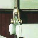
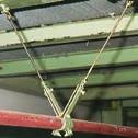


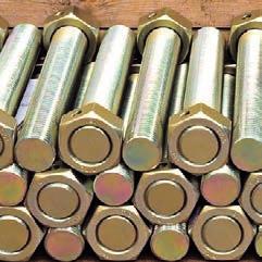
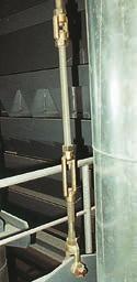

237
238 Thread connecting elements Contents Page Threaded connections 60 to Selection tables ye nuts Threaded clevises with pin Turnbuckles Rod couplings Connecting rods Selection tables Tie rods L/R Hexagon nuts Stud bolts Tie rods Threaded rods PRODUCT6 GROUP
239 Threaded connections Type 60 to 64 Precision-fit threads, reliable material properties and design with sufficient load reserves are prerequisites for the reliability of the whole load chain. The connections in product group 6 are specially shaped bolting components to attach the connecting rods to other support components. They connect components in the load chains with their counterparts, such as lugs, clevis or eye plates. The connections in product group 6 form an independent group within the modular system and were specially designed for optimum use as pipe support components. They are largely drop forged and, except for turnbuckle 62, so designed that they enable a little length regulation despite low installation heights. ye nut 60 The permissible loads correspond to the load tables for statically determined components on page 0.6 of the technical specifications. Threaded clevis with pin 61 Turnbuckle 62 Rod coupling 64 ye nut 60 is used as a transition from a rod to a pin connection; threaded clevis with pin 61 joins a rod to a lug connection. Turnbuckle 62 is fitted with a right-hand thread on one side and a left-hand thread on the other. It is used in combination with tie rod 65 for length regulation and the pre-stressing of load chains. If required, rod coupling 64 is used to form rod lengths longer than 12 foot [3.66m]. ll threads (except in turnbuckle 62) are right-hand and available in both UNC and metric versions. For corrosion protection the components are electro galvanized as standard, coating thickness approximately mil [12-15µm]. For use in particularly aggressive atmospheres hot dip galvanized components can be supplied. If required, the components can be supplied with material certificates. It is often necessary to use the connection components in areas above the standard field of application, where higher temperatures apply. The LISG connections offer special benefits: universal application possibilities load and connection compatibility with the LISG modular system drop forged and heat-treated electro galvanized as standard, hot-dip galvanized if required approval through special tests For this, LISG S offers products made from the material 10CrMo9-10 for the connection to special designs (see page 4.9). The upper load limits for use up to 500 C corresponds to the nominal load (see chapter on page 0.5) of the respective load groups. The numbers are described as follows: ye nuts Threaded clevises with pin : HT; (60 D9 04-HT to HT) : HT; (61 D9 04-HT to HT) Turnbuckles : HT; (62 D9 04-HT to HT) Rod couplings : HT; (64 D9 04-HT to HT) 6.1


240 ye nuts Type 60 Threaded clevises with pin Type 61 6 d 3 F ye nuts 60 D9 19 to G Material: P250GH drop forged. X Ø d 2 C D From load group 40 welded design material: S3552. C D Ø d 2 d 3 F G X weight 60 D M M M M M M M M M M56x M64x M68x M72x M80x Order details: eye nut G H F K d 1 Threaded clevises with pin 61 D9 19 to X ød 2 L C M D shape , C D Ø d 1 Ø d 2 F G H K L M X weight 61 D M x M x M x M x M x M x M x M x M x M56x x M64x x M68x x M72x M80x Material: P250GH From load group 10 and further material: S3552, drop forged. From load group 40 and further flame cut design material: S3552. Pins C35+QT complete with cotter pin DIN N ISO 1234 and washers DIN From load group 40 and further material: S3552. Order details: threaded clevis with pin


241 Turnbuckles Type 62 Rod couplings Type 64 Turnbuckles 62 D9 19 to Material: S235R drop forged. From load group 10 flame cut design material: S3552. X SW b L C Ød 2 a One side right-hand, other side left-hand thread. b The ends of the threaded rods must not come into contact. Order details: turnbuckle C SW Ø d 2 a L X weight 62 D M x M x M x M x M x M x M x M x M x M56x x M64x x M68x x M72x x M80x x Rod couplings 64 D9 19 to Material: S235R drop forged. b L From load group 10 flame cut design material: S3552. Ød 2 C D Order details: rod coupling C D Ø d 2 L weight 64 D M10 11x M12 11x M16 14x M20 17x M24 22x M30 23x M36 28x M42 32x M48 40x M56x4 80x M64x4 90x M68x4 100x M72x4 100x M80x4 120x


242 Connecting rods Type 63, 65, 66, 67 6 pplication Threaded and tie rods connect the support components to each other in order to bridge installation heights. They can be used as rigid supports with the connection components and in elastic load chains with spring and constant hangers. Materials and loads Only materials with guaranteed mechanical properties regarding good homogeneity and sufficient charpy-test values (ductility) are used. The permissible loads correspond to the load table for statically determined components in the technical specifications on page 0.6. Rolled threads ll threads are manufactured in a rolling process. y rolling the threads are not cut. Through the rolling process the material is made to flow and is plastically formed. In this way the surface is given additional notch-free high-quality strength. Friction resistance is thereby reduced; this has a favorable effect on any adjustment of the rods under load. On top of that, safety reserves exceed ing the demands of the design specifications are created. Designs Threaded rods 67 with continuous threading up to M48 and tie rods 66 (from M20) are available in fixed 500mm length increments in the length range from 500mm up to 3,000mm. The tie rods have thread lengths of 300mm on one side and 600mm on the other. The short thread is for length adjustment, e.g. as a connection for spring and constant hangers. The long thread is for the fitted length. This can be shortened as required according to the installation height on site. Standard lengths Larger tolerances in the building structure have led to increasing problems with fitted lengths instead of easier installation, especially when the connection threads are too short. The use of standardized fixed lengths is therefore more and more common because of their greater flexibility. Fitting can be easily carried out with hanging rods already mounted at the upper end. Laborious measurement with the risk of error is thereby avoided. Structural tolerances can be compensated for. Length adjustment Tie rods 65 with right-hand / left-hand threads are always used in combination with turnbuckle 62 and fitted with standard lengths. They are designed for length adjustment and force-fit prestressing of load chains. ll other bolted connections are exclusively right-hand threads and on installation must be locked with a hexagon nut 63. Corrosion protection For corrosion protection all rod s are electro galvanized, layer thickness approx µm. If required, hot-dip galvanization is available. Hot dip galvanized threaded rods M10/M12 are available in lengths up to 1,000mm. Longer length can be prepared by rod couplings. Certification If required, all components can be supplied with certificates according to DIN N or 3.1. Special properties: materials with proven characteristics rolled threads notch-free surfaces electro galvanized surfaces standard lengths in-house manufacture Often there is a need to use the connecting members even in areas which are above the standard range of application and can exposed to with higher temperatures. For this LISG S offers products made from the material 21CrMoV57 or 25CrMo4 for hex nuts for the connection to special designs (see page 4.9). The load limits for use up to 500 C correspond to the nominal load of each load groups. The numbers are described as follows: Tie rod L/R : HT; (65 D1 03-HT to HT) Stud bolt : HT; (67 D1 03-HT to HT) Threaded rod : HT; (67 D2 03-HT to HT) Tie rod : HT; ( HT to HT) Hexagon nut : ; (63 D9 39 and to ) The pipe systems are embedded in load chains, where the connecting rods are important elements. When selecting them great attention must be paid to quality so that these seemingly simple components do not form the weakest link in the chain. The decisive factors for their load-bearing capacity are, beside adequate dimensioning, material quality and design conforming to standards. Manufacture of threaded components Fiber flow of rolled thread 6.4


243 Tie rods L/R Type 65 Hexagon nuts Type 63 Stud bolts Type 67 Tie rods left-hand/right-hand 65 D1 19 to Material: M10 to M16: S235R from M20: S3552. L 1 L 2 Ød L Ød2 LISG threaded rods should only be replaced in kind. right left Order details: tie rod L/R Ø d Ø d 2 L L 1 right 65 D M M M M M M M M M M56x M64x M68x M72x M80x L 2 left weight Hexagon nuts 63 D9 29 to Material: grade 8 hexagon nuts DIN N ISO 4032 as counter nuts for threaded rods M10 M80x4. Stud bolts 67 D1 19 to Material: M10 to M16: S235R from M20: S3552. LISG threaded rods should only be replaced in kind. Order details: hexagon nut size weight 63 D9 29 M M M M M M M M M M56x M64x M68x M72x M80x L Ø d 2 weight 67 D M M M M M M M M M Order details: stud bolt


244 Tie rods Type 66 Threaded rods Type 67 6 L threaded rod 67 L Ø d2 Ø d2 Threaded rods / tie rods 67 D2 19 to / to Material: M10 to M16: S235R from M20: S3552. LISG threaded rods should only be replaced in kind. tie rod 66 designation at L= Ø d weight [kg/m] M D D D D D D M M M M M M M M Standard lengths avoid problems caused when installation lengths are too short. They can be flexibly adapted by shortening to suit the installation situation on site. Order details: threaded rod / tie rod a L threaded rod 67 a L L 1 L 2 Ø d2 Ø d2 Connecting rods from M56x4 can be supplied as threaded rods 67 or as tie rods 66 with individual rolled thread lengths. tie rod 66 a L=max. 6,000mm, longer lengths on request Ød 2 designation (L / L 1 / L 2 please note at order) weight [kg/m] M 56x M 64x M 68x M 72x M 80x Order details: from M56x4: threaded rod / tie rod L = mm L 1 = mm L 2 = mm 6.6
245 Structural attachments, trapezes, clamps, slide plates 7 trapezes, Structural attachments, clamps, slide plates PRODUCT 7 GROUP

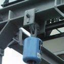

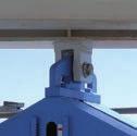
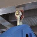
246
247 Structural attachments, trapezes, clamps, slide plates Contents Page Structural attachments, trapezes Weld-on clevises Weld-on eye plates Weld-on plates with spherical washer Clamps and trapezes eam clamps Trapezes eam adapters Guides with beam adapters 76 for clamp bases Cantilevers with beam adapters Slide plates Instructions on assembly and installation Slide plates to weld-on Slide plates for bolting PRODUCT 7 GROUP
248 Structural attachments, trapezes, clamps, slide plates Special components for welding or clamping are available for connecting the pipe supports to the supporting structure. In order to fulfill safety requirements the connections must be suitable. Product group 7 Connecting components for the direct attachment to the structure and trapezes form part of product group 7. The permissible loads for the components correspond to the load table for statically determined components in the technical specifications, page 0.6. For weld-on clevises 73 well suited for connection to hollow sections - and weld-on eye plates 75 the specified minimum weld seam thicknesses must be taken into account. These are calculated not to exceed a maximum weld seam stress of 75N/mm 2 (load case H / level /). n angulation of up to 6 was considered in the basis of the load calculation. The weld-on plates 74 enable use of the maximum pendulum length in restricted spaces by means of a plug connection. Here too, an angulation of up to 6 was considered in the basis of the load calculation. The hot dip galvanized beam adapters 76 allow clamp connections instead of welded connections, for example at extensions of piping systems or steel structures in existing plants. eam clamps 78 are designed for weld-free connection on site. They are suitable for all beam widths and flange slopes. When ordering, please state beam widths and flange thicknesses. For protection against corrosion the components are given a weldable primer coating (30µm) or are electro galvanized (layer thickness 12-15µm). Trapezes 79 are for the attachment of clamp bases 49 and 56 and can be used for rigid suspension as well as for connection with spring and constant hangers. The trapeze profiles are protected against corrosion according to LISG standard color coating (see page 0.10). ll components can on request be supplied with material certifications Standardized connection possibilities


. Order details: weld-on clevis 73.. 1.")


249 Weld-on clevises Type 73 Weld-on eye plates Type 75 7 l F H G a M d 1 K shape to Weld-on clevises to Material: S3552 drop forged. From load group 20: flame cut design made of S3552. pin: C35+QT. Ød 1 F G H K M min. weld seam a weight x x x x a Calculation of the weld seams was based on a permissible stress of 75N/mm 2 in load case H (level /). Order details: weld-on clevis a s Weld-on eye plates 75 D1 19 to Material: S235R From load group 6: S3552 C d3 Ød 3 C s min. weld seam a weight 75 D a Calculation of the weld seams was based on a permissible stress of 75 N/mm 2 in load case H (level /). Order details: weld-on eye plate


250 Weld-on plates with spherical washer Type 74 Weld-on plates with spherical washer 74 D1 19 to Ø R Material spherical washer: case-hardened steel. From load group 5: C15. weld-on plate: S235R. For s M 20: S3552. a Ød 4 s G 6 6 ØD max. F l a LISG recommends tack welding of the weld-on plate for fixing positions or welding all round as specified. for rod Ø ØD Ød 4 max. F G R s weight 74 D1 19 M M M M M M M M M M M M M M M M M M M56x M64x M68x M72x M80x Order details: weld-on plate with spherical washer


.")


251 eam clamps Type 78 Trapezes Type 79 7 Trägerklammern Typ bis b Surface: electro galvanized 0 t = 0 t d 3 s d 3 0 up to beam width b= s t max b weight a a Load sizes can also be connected. The permissible load amounts to 100kN in load case H (level /). b Larger t dimension possible on request 0 increases correspondingly. When ordering please state beam width b and flange thickness t. Order details: beam clamp beam width b = mm flange thickness t = mm Ød 4 L m 80 a b a a Trapezes for the use of lower loads at temperatures m 80 C 79 C2 37 to a The permissible center load is to be taken from the respective trapeze load group (3 rd digit in the designation). L max a b Ød 4 L= 1000mm w per 100mm weight for 79 C D Order details: trapeze , L = mm 7.4
252 Trapezes Type 79 Trapezes to L m 100 s d 3 a U a The permissible center load is to be taken from the res pective trapeze load group (3 rd digit or 3 rd and 4 th digits in the designation). b The L max dimensions can be lengthened up to 2400mm on load reduction of 5% per 100mm extension. c Connection possible for the specified load groups. Order details: trapeze , L = mm Trapezes to load c group d 3 M s m L max b U weight for L= 1000mm w per 100mm D D L C s d a The permissible load for the middle connection is to be taken from the respective trapeze load group (3 rd digit in the designation). Ød3 U b L max can be lengthened to 2400mm for to on reduction of the permissible load by 5% for every 100mm. c Connection possible for the specified load groups. Order details: trapeze , L = mm 7.5 load c group d 3 L max b U C s weight for L= 1000mm w per 100mm D D On request s and can be delivered. a s


253 eam adapters Type 76 7 On alterations or extensions of the pipe systems or steelwork in existing plants, clamp connections are frequently preferred to welded connections. Clamp connections are strictly specified in cases where welding connections are excluded for safety reasons. The safety of the clamping effect of such connections depends essentially on the nature of the existing contact surfaces and the prestressing forces applied. The design of the clamping components used is therefore decisive for a reliable connection. For the creation of safe and reliable clamp connections LISG offers the beam adapter system 76. These components enable the connection of very different components to existing steelwork without welding or drilling. ssembly is simple and timesaving. On tightening, LISG beam adapters adjust independently to the existing beam thickness. If the specified tightening torques are observed, lasting security of the connections is guaranteed. ny corrosion protection already present, such as hot-dip galvanization or paint coatings, incurs no damage. The special support segments are the main feature of the LISG beam adapters. Due to their shape they automatically adapt to any position and to existing profile angles. eam adapters 76 D2 11 to Material: cast iron hot dip galvanized a t H Ød 2 a The loads specified correspond to this in load case H (level /) Max. permissible loads page 0.6. For further load cases see table. on bolting 8.8 support load torque value [kn] a [Nm] max b Ød 2 H min H max t (clamp thickness) min max weight 76 D M M M M b Friction value µ = Order details: beam adapter (without bolt) bolts for beam adapters, see page


 thickness of intermed.")
254 The hardened support segments have a circular groove profile that is pressed into the contact surface on tightening. This way, a form-fit contact is produced which ensures that no shifting in any direction takes place. xample of connections with beam adapters Cross-connection The safe connection of beam profiles to each other is produced very easily with an inlay plate and 8 LISG beam adapters. The load-bearing capacity of a cross-connection can be found in the table below. Typical utilization of beam clamps at different material thicknesses xample of use: ttachment of clamp base to steel beam olts for beam adapters bolt dimensions weight 76 D M10 x D M10 x D M10 x M12 x M12 x M12 x M16 x M16 x M16 x M20 x M20 x M20 x Load-bearing capacity of cross-connections with LISG beam adapters Profile connection load capacity [kn] with 4 bolts (8.8) thickness of intermed. plate 76 D Hexagon bolts DIN N ISO 4017, thread to head, grade 8.8, hot dip galvanized, including a hexagon nut DIN N ISO 4032, grade 8, hot dip galvanized. Order details: bolt for beam adapter The connection of profiles to each other can be made either directly or by using an inlay plate. 7.7

![b F x [kn] F z a total weight [kn] a 1 a 2 b min c t max for b=100 + per 100mm 76 00 11 76 00 21 35 1.0 3.5 30 50 42 40 15 1.7 0.60 76 00 12 76 00 22 70 1.7 4.5 30 60 50 45 17 2.8 0.](/docs-images/93/114255555/images/255-1.jpg "95 76 00 13 76 00 23 150 2.8 6.5 40 80 64 55 20 4.9 1.40 76 00 14 76 00 24 300 4.7 6.5 40 80 73 65 25 7.2 1.")
 Fz: the permissible short duration lift-off load is limited in every case by the permissible lift-off load of the clamp base. See page 4.68 for this. Order details: lateral guide 76 00 1.")

255 Guides with beam adapters Type 76 for clamp bases Type 49 Cantilevers with beam adapters Type F a z Guide with beam adapters for clamp bases to L= b + 2c c Material: guide S235R F x a1 t a 2 b lift-off restraint a a with lift-off restraint torque value [Nm] b F x [kn] F z a total weight [kn] a 1 a 2 b min c t max for b=100 + per 100mm a If required, the guides can be supplied with an additional lift-off restraint (width 80mm). (When ordering also specify clamp base.) Fz: the permissible short duration lift-off load is limited in every case by the permissible lift-off load of the clamp base. See page 4.68 for this. Order details: lateral guide , b = mm Order details: lateral guide with lift-off restraint (clamp base ), b = mm b Friction value µ = 0.14 c b Cantilever with beam adapters 76 C1 16 to Material: cantilever S235R a t s Ød 4 L L min = 0 mm L max = b 2 + c torque value [Nm] a a x s b min b max c Ø d 4 t max weight for b=100 L=50 + per 100mm 76 C x D x x x a Friction value µ = 0.14 Order details: cantilever with beam adapters b = mm, L = mm 7.8


![1 17 b = mm, L = mm a torque value L max up to beam width b= [Nm] a x s b min c](/docs-images/93/114255555/images/256-2.jpg "Ød 3 e t max 82 100 125 140 180 220 260 300 weight for b = 100 + per L = 100")


256 Cantilevers with beam adapters Type Cantilevers with beam adapters s 76 C1 17 to c b Material: cantilever S235R Ød 3 a e t L s L L = b 2 + c a Friction value µ = 0.14 Order details: cantilever with beam adapters b = mm, L = mm a torque value L max up to beam width b= [Nm] a x s b min c Ød 3 e t max weight for b = per L = mm 76 C x D x x x xample of use: roller bearing fitted at works with lateral support plates xample of use: clamp base on trapeze 7.9

257 Slide plates Type 70 pplication and field of use The pipe systems resting on pipe bearings are subject to displacement as a result of thermal expansion. This displacement must be permitted to prevent unacceptable stresses that could damage the piping system. Furthermore, the slight friction caused by these movements is reduced by inserting slide plates between the clamp base and supporting framework. During the planning phase the reduction of friction forces is extremely important. Since friction forces can represent considerable additional forces to the operational loads, they are usually distributed into the supporting framework (building structure or secondary steelwork) by the use of low friction materials/surfaces. y lowering friction forces the dimensioning of building structures and secondary steelwork can be, under the aspect of cost saving, reduced. lso the reaction forces in the pipe statics. Slide plates are commonly used in all pipe systems in industrial processes / chemical plants, in the power station field, in liquefied gas transport or in district heating pipe systems. Through the use of slide plates friction forces can be reduced about 60%. Instead of steel / steel sliding contact with a friction coefficient of µ P 0.3, through the use of slide plates and a stainless steel plate as a counterface on the clamp base side the friction coefficient can be reduced to as little as µ P 0.1 (dry). LISG slide plates consist of different low-friction materials for different temperature ranges. For use at a constant temperature up to 180 C (at the bottom of the clamp base) the standard PTF slide plate is recommended. For temperatures above 180 C to a maximum of 350 C a special high-temperature material is used. dvantages of the low-friction materials high mechanical wear resistance temperature resistance up to 350 C suitable for use in aggressive environmental conditions due to their high chemical resistance self-lubricating permanent freedom from maintenance long lifespan excellent load-bearing capacity 7 Clamp bases are seated on slide plates allowing movement with reduced friction this means the pipe systems can move without constraint during thermal expansion. Weld-on slide plates Type 28 with embedded slide plates Type 29 with load plate and PTF slide plates Typical use of slide plates under clamp bases 7.10


258 Other fields of application for LISG slide plates are uses where heavy loads must be moved horizontally. y using slide plates the force required for movement can be reduced by as much as 60%. The use of slide plates has a favorable effect on the whole pipe system layout. uild of the slide plates LISG slide plates for the temperature range up to 180 C are made of the low-friction material PTF. For temperatures from 180 C up to 350 C a special high-temperature material is used that not only increases heat resistance but also optimizes the mechanical properties. The LISG slide plate to weld on consists basically of a supporting plate of carbon steel with a weldable primer coating in which the low-friction material is embedded. Optionally these supporting plates can be supplied hot dip galvanized. The LISG slide plates for bolting are hot dip galvanized as standard. The counterface is a stainless steel plate. Optionally the stainless steel plate, that must be ordered separately, can be welded to carbon steel support plate or it is attached to the bottom of the clamp base in the factory and can be used immediately. Use of slide plates for pipe guides G.. Specially developed for vertical installation, such as for example for G.. pipe guides, the slide plate is bolted to the support plate stainless steel plate M slide bearing / guide through clamp base G3-SP with slide plates X-Z-stop with guide in Y direction through clamp base Type G4-SP with slide plates 2 1 z y x Friction values µ in dependence on operating temperature slide plates max. operating temp. 150 C 180 C 280 C 300 C 350 C standard PTF sliding material µ 0.1 high temperature sliding material 0.1 µ 0.18 µ


259 Information on construction and assembly of slide plates Parallel installation of the slide plates and counterfaces is required In every possible bearing position the slide plates must be fully covered by the counterfaces. The components are to be fitted so that any bending of the slide plates or counterfaces is prevented. 3 Installation of slide plates Clamp base 49 on slide plate with clamp connection to steelwork Type Is tack-welded with single datum points. If all-round welding is required, the temperature of the PTF material must not hereby exceed 260 C. When welding, the PTF material or the restraining surfaces of the support plate must be protected from dirt. It is recommended to install the slide plates only horizontally. For vertical installation M is to be used. When it has been ensured that the counterface is always in contact with the PTF, the standard component shape can also be used. Type and are bolted to the steelwork with M10 or M12 cylinder bolts. These bolts do not form part of the scope of supply. Special sizes can be supplied on request. Clamp base 49 and spring support 28 with slide plates Recommended use of slide plates for spring supports
260 Slide plates to weld-on Type 70 Slide plates to weld-on (rectangular shape) to Material: S235R Surface: weldable primer a The 6 th digit is to be filled out in dependence of the operating temperature. b For friction values of slide plates: see table on page Order details: slide plate to weld-on H D max. load [kn] sliding surface weight a 150 C 180 C 350 C b H D x Ø x x x x x 30 x x 30 x x x x x x 80 x x 80 x x x x x 130 x x 130 x x x x 180 x x 180 x Slide plates to weld-on (round shape) to Material: S235R H ØL ØD Surface: weldable primer a The 6 th digit is to be filled out in dependence of the operating temperature. b For friction values of slide plates: see table on page max. load [kn] sliding surface weight a 150 C 180 C 350 C b ØD H ØL Order details: slide plate to weld-on
261 Slide plates for bolting Type 70 max. load [kn] sliding surface qty weight a 150 C 180 C 350 C b H D x C F G holes Ød Ø x x x x x 30 x x 30 x x x x x x 80 x x 80 x x x x x 130 x x 130 x x x x 180 x x 180 x H 6 D F C Ød G 7 Slide plates for bolting (rectangular shape lengthwise) to Surface: hot dip galvanized a The 6 th digit is to be filled out in dependence of the operating temperature. b For friction values of slide plates: see table on page Order details: slide plate for bolting H 6 Ød ØD ØL ØTK (3x120 ) ØD Slide plates for bolting (round shape) to Surface: hot dip galvanized max. load [kn] sliding surface weight a 150 C 180 C 350 C b ØD ØOD H ØL ØTK Ød a The 6 th digit is to be filled out in dependence of the operating temperature. b For friction values of slide plates: see table on page Order details: slide plate for bolting
262 Slide plates for bolting Type 70 Slide plates for bolting (transverse rectangular shape) to Surface: hot dip galvanized H 6 G C Ød D F a The 6 th digit is to be filled out in dependence of the operating temperature. b For friction values of slide plates: see table on page Order details: slide plate for bolting max. load [kn] sliding surface qty weight a 150 C 180 C 350 C b H D x C F G holes Ød x x x x x 30 x x 30 x x x x x 80 x x 80 x x x x 130 x x 130 x x x 180 x x 180 x Material: S235R Surface: weldable primer Supplementary order details: slide plate M Slide plate M for vertical or overhead installation 7.15
263 LISG software tools for planning and design 8 for LISG Software Tools Planning and Design PRODUCT 8 GROUP
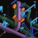

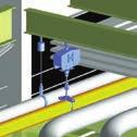


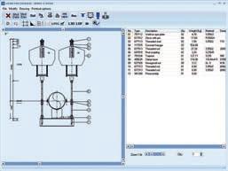
264
265 LISG software tools for planning and design Contents Page LISG software tools for planning and design Planning software LICD Interfaces and component libraries PRODUCT 8 GROUP 9 8.0


266 LISG software tools for planning and design The intelligent solution for support design LISG s unique modular system was the prerequisite for the creation of highly sophisticated user software. The solutions we offer open up new opportunities for increased efficiency in design, optimized quality and significant savings in project man-hours. In general, the model design of plants is carried out with CD, including C systems. Through the integration of LICD into different CD systems, the benefits for the efficient layout of piping systems have been vastly improved. The LICD program has set new standards in this field. It enables the creation of support drawings and lists of materials in minutes instead of hours. LICD is an intelligent frontend program that supplies the necessary interface data from only one source for all CD programs currently in use. From the point of view of quality this single-source function is particularly important. To provide the LICD user with the widest possible range of applications, LISG has developed supplementary user software. The whole package covers: Stress analysis Pipe supports Planning of a plant LICD 3D planning Steelworks LICD planning and design program for pipe supports Interfaces for import and export of tables and databases Interfaces with 3D-CD component packages 2D / 3D libraries for different CD programs Internet communication system for downloading the latest program versions and information on projects, including drawings and orders Interface to stress analysis and steelwork software LICD is a registered trademark of LISG S. ll other products, fonts and company names are trade names or registered trade names of the respective companies. Support configurations can be integrated via the export function into complex 3D views. 8.1


267 Planning software LICD 8 Software with profit effect Needed first designed last s a rule the project planning of complex pipe systems runs through numerous phases of optimization. The design of pipe supports inevitably takes place at the end of the whole process and so their deployment frequently comes far too late. lthough the supports are needed on site beforehand for optimum installation of the pipe systems, they lie right at the end of the planning chain - all the more important to avoid unnecessary delay. The time factor is now crucial. LICD speeds up the planning process LICD, the LISG design program for pipe supports, sets the highest standards in efficiency. With LICD the laborious poring over catalogs and the paintaking preparation of lists of material are a things of the past. Support designs and load chains no longer need to be manually configured and then drawn up at great expense and effort. What would otherwise take hours to produce can be done by computer in minutes at the click of a mouse! Highly efficient design software for pipe supports Future-orientated logistics With LICD, great savings in time are possible in the logistics process, from planning right through to delivery. For example, the LICD data can, if required, be transmitted directly for processing on the same day by as a computerized order list. This fits in perfectly with ever-tighter order deadlines. The downloading and use of LICD is free of charge. In the current version the following languages are available for menu navigation and print editions: Chinese, German, nglish, French, Italian, apanese, Polish, Portuguese, Russian, Spanish and Hungarian. utocd drawing, generated on the basis of a LICD design 8.2


268 Free determination of axes LICD is simple to use The relevant data for industrial support points is entered using menu-driven program control. Only 6 parameters are needed to find the optimum solution. pipe diameter temperature of medium operating load displacement installation height support configuration From this input, the appropriate load chains are automatically generated. The selection of optimum spring and constant hangers thereby follows automatically, whereby the specific customer requirements such as, for example, travel and load reserves according to SM 31.1, VG-R 510 L, DIN N or other optimum parameters are taken into account. This is ensured by the corresponding entries in the options menu. Taking this information into account, LICD s programmed algorithm chooses the most economical solution. True-to-scale drawings The support chains created are automatically saved as complete assemblies and can be printed out as drawings or modified at any time. They are true to scale and contain all relevant details, including parts lists with weights and materials and optionally with location plan or other freely editable information. LISG modular system forms the basis The basis of the program is a database system in which the whole LISG standard product program is stored as a modular system of absolute functionality. From more than 12,000 standard components, all fully compatible regarding loads and connections, more than 100 standard configurations cover practically all normal installation situations. Further options for editing of drawings ll essential functions at a glance LICD drawing generated by a standard printer 8.3


269 Smart 3D (Intergraph), PlantSpace (entley Systems), Plant 3D (utodsk) or PDMS (VV). Planning continuity, as well as the need to consider possible interference, make it necessary to fully include the pipe supports. 8 Clearly arranged queries on the essential data for the support in question Location plan with axis designations and dimensioning Support design with detailed parts list uxiliary designs for steelwork LICD generates ready-to-install load chains from standard supports, from structural attachment to pipe-surrounding component. More or less complex auxiliary designs are necessary for connection to the existing structures (secondary steelwork). LICD saves up to 50% of planning costs LICD runs smoothly on any modern PC with Windows and is easy to use. Due to its particular effectiveness LICD has long been an indispensable tool in support planning for countless engineering offices. Potential savings in costs of up to 50% simply cannot be ignored! Through its special interface the LICD designs can be exported into a separate CD program (e.g. utocd, MicroStation ) and supplemented as required. Interference checks For larger plant projects the design of the building structure, including steelwork, main components and connecting piping system, is carried out via 3D CD programs such as Possible savings in costs through LISG pplication enefits (L) 8.4


 can continue to be included and used in the selection of the appropriate supports. The data gained from the C systems can be sent directly to CD programs after generation of the supports.")
270 Interfaces and component libraries LICD contains a wide range of interfaces and component libraries for well-known C, CD and steelwork programs. This benefits resources and makes for significant savings in time when designing pipe systems! Interfaces and C systems broad spectrum of interfaces enable the import and export of data already entered from, and to, CD and C systems. This basis of the selection of a support chain is formed by the design data from the pipe calculations of the pipe system. One of the C systems is the ROHR2 program system (Sigma Co.), which is used for the static and dynamic analysis of complex piping systems and common skeletal structures. The interfaces to the C systems mentioned above are part of the basic LICD package. Optional interfaces for downloading can be found on the LISG homepage. Import of design data Pipe stress analysis with ROHR2 xport of design data from CSR II for LICD Pipe stress analysis with CSR II Data from utopip (entley systems) or CSR II (Intergraph Co.) can continue to be included and used in the selection of the appropriate supports. The data gained from the C systems can be sent directly to CD programs after generation of the supports. This procedure enables a considerable increase in efficiency and savings in time when designing complex pipe systems. Interfaces to CD programs Via defined interfaces the LICD support designs can be transmitted true to scale and without any further efforts to the known CD programs. LICD supports the export formats DXF, LOF, L3D and ITM. The data are used for the transmission of graphic information and design data. The relevant additional applications are available in the CD systems for the import of these data. 8.5
. This interface is part of the basic LICD package.")

271 8 Pipe systems in utopip xport of 2D data Via a DXF export file the support designs, including dimensioning, can be exported optionally with parts lists, site plans, and title block to CD programs (e.g. utocd or MicroStation ). This interface is part of the basic LICD package. For export, the material list (STL) and design data (TC) files are additionally generated; they can be used for further evaluations. xport to 3D CD programs On the basis of component libraries the drawings prepared in LICD can be transformed into 3D drawings via add-ons in various CD programs. This is possible for: utocd, utodesk utocd Plant 3D, utodesk MicroStation, entley Systems SmartPlant 3D /Smart 3D, Intergraph PDS, Intergraph SUPPORT MODLR, Intergraph For the above mentioned programs the corresponding modules are to be uploaded and installed. For the PDMS software from VV no add-on is registered. menu extension is available by which data can be conventionally imported and exported. utopip hanger filter LICD plug-ins LICD plug-ins for different systems are also available. These are used in cases where supports are to be designed interactively in a 3D model. The advantage of a plug-in is that the geometric data of the connection points for the support, as well as pipe diameters, height notations and, if required, the design data are exported directly to the program. There is no longer any need to take measurements in the model. The support chain is automatically displayed in the 3D model. Model in PDMS after data import from LICD The attributes of the material lists are also imported, depending on the system. Important: In order for the plug-ins to function, LICD must be installed at the respective work station. 8.6


. It therefore makes sense to be able to display standard supports in steelwork programs. For this, LICD provides interfaces to steelwork programs (e.g. TKL Structures software).")
272 LISG standard supports in SmartPlant 3D LISG supports in CDWorx Component Libraries For further designing in the 2D and 3D modes, comprehensive LISG component libraries are available, amongst other things, for the following CD programs: utocd, utodesk utocd Plant 3D, utodesk MicroStation, entley Systems SmartPlant 3D / Smart 3D, Intergraph PDS, Intergraph PDMS, VV SUPPORT MODLR, Intergraph TKL Structures, TKL Interface to steelwork programs Through LICD, the most suitable standard support configurations for each case are determined and from this the corresponding load chains, including all individual parts, are specified. In plant construction, standard supports are the connecting links between pipe systems and steelwork. In ideal cases they can be directly connected to the existing plant structure, but often a further step is necessary, that is, the use of additional steelwork components as con n- ecting elements (secondary steel). It therefore makes sense to be able to display standard supports in steelwork programs. For this, LICD provides interfaces to steelwork programs (e.g. TKL Structures software). y means of the plug-in function, LICD is integrated into the steelwork program and supports can be directly planned in accordance with the re quire ments of the model. LISG component library in TKL 8.7


273 8 LICD plug-in for TKL Structures Simple modeling and rapid alteration of 3D models This, together with all other plant components in the model, enables the execution of a clash check, which is necessary when planning complex plants. Interactively designed support in TKL Structures With the development of the steelwork interface LISG supplies a tool that can reduce the enormous investment in time and so optimize the quality of the planning process. Primary steelwork and pipe systems with supports as reference in TKL LICD updates LICD and other software packages are being constantly updated and expanded. The applicable program version and interfaces in each case can be found on the LISG homepage for downloading. The necessary license numbers are thereby forwarded automatically by to the recipient. Further license numbers can be obtained by telephone. The use of LICD software is free of charge. 8.8
274 Supplementary services, engineering, field service 9 engineering, Supplementary services, field service PRODUCT 9 GROUP
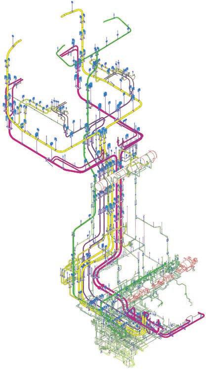
275
276 Supplementary services, engineering, field service Contents Page Supplementary services ngineering support design Field service PRODUCT 9 GROUP 9.0


277 Supplementary services The LISG product program presented in this catalog STNDRD SUPPORTS incorporates the latest technical developments with respect to the proper support of pipe systems in industrial plant construction. The relevant international stipulations are observed to the fullest extent. Special fields of application The standard design described covers the normal field of application. In special sectors, for example, nuclear or offshore installations, supplementary measures with regard to material quality or corrosion protection may be required. The implementation of particular customer specifications is ensured by the integrated quality management system. Certificates of approval are supplied with the order. Service areas The LISG performance package includes not only the product spectrum but a range of services within the framework of product application. In the field of engineering they cover the whole process chain from pipe system design to support planning in all the current 3D design sectors. The service field comprises the usual support when commissioning, right through to plant analyses and walk-downs. Through the use of specially developed software for support design highly effective support is available, e.g. in the 3D CD sector. Standardized supplementary services y means of tightly-focused supplementary services the LISG standard program can be adapted to particular requirements. In this way the field of application of the products is widened and the LISG performance package optimized. ll major supplementary services are standardized in line with the LISG modular system and cataloged in product group Supplementary services 9.1 djustment work Constant and spring hangers/supports are adjusted to installation load on a hydraulic test bench via computerized force and travel measurement, then blocked Storage of the blocking devices On request the spring hangers/supports can be equipped for permanent storage of the blocking devices (after deblocking) on the casing. This is standard practice on the constant hangers. 9.2 Quality assurance Inspection reports If required, inspection reports with digitally recorded values can be supplied as function verification for constant hangers, spring hangers and snubbers In-service tests In-service tests can be performed on the mechanically operating components of any make in the respective LISG factories or by using mobile test benches directly within the plant itself Material certification The following material certification can be supplied on request Supplier s certificate Manufacturer and shipment in compliance with the order can be confirmed with a supplier s certificate according to DIN N Material certificates DIN N The materials used in all catalog components can be verified by verification certificates according to DIN N Compilation of component documentation


278 9.2.6 cceptance test certificates DIN N Components exposed to the direct flow of force such as, for example, the springs in constant and spring hangers or supports, can be supplied with certificates according to DIN N Complete traceability through acceptance test certificates DIN N Due to separate fabrication, complete traceability is possible of materials in all catalog components with test certificates according to DIN N Pre-examination documents The standardized products were largely certified by independent inspection bodies by specified suitability and tests according to KT and VG-R 510 L. Pre-examination documents such as design draw ings, parts lists, calculations, test sequence schedules and welding plans can be produced for special designs, particularly non-standardized components (also for other codes) Increased quality requirements For applications subject to increased safety and quality demands, such as nuclear installations, the highest level of the quality assurance program is implemented. ll stages of order processing and execution are followed according to recognized procedures, in line with the quality stipulations in the standard codes KT or SM section III, NC and NF. The following areas are thereby taken into special account: material acquisition from approved suppliers complete traceability of materials strict supervision of manufacture Cataphoretic immersion priming 9.3 Surface treatment In addition to specified standardized surface protection, further corrosion protection can be supplied according to technical specifications, from page Spray painting ll areas are fully documented. 9.2


279 Pre-assembly of load chains Special treatment esides the standard designs available from stock, special designs providing extra corrosion protection can be agreed on. For this, separate manufacturing may be required. 9.4 Pre-assembly If not otherwise agreed, the components belonging to one scope of supply will be packed in bundles according to s Pre-assembly of load chains For simple handling and time-saving assembly at site, the individual components are supplied already pre-assembled into load chains, according support drawings bundled and marked. Constant and spring hangers/supports, as well as larger pipe clamps (bulky components), are kept separate for easier handling and are correspondingly marked Pre-assembly of pipe clamps and clamp bases Pipe clamp and clamp base halves are bolted ready for shipment and supplied as complete units. 9.5 Labelling and marking If not otherwise agreed, the components are sorted according to, packed and marked with quantity, number and order number. dditional labeling and marking can, if required, be applied Marking of individual parts If required, all components can be marked individually with, support position number or order number Second name plate If required, spring hangers and constant hangers can be fitted with a second name plate Second load and travel scale If required, constant spring hangers/spring supports can be fitted with a second travel scale and constant hangers/supports with a second load scale. 9.6 Packaging ppropriate forms of packaging are provided for the various requirements. Load chains, pre-assembled, bundled and marked 9.3


280 9.6.1 Inland packaging For road or rail transport, sturdy wooden crates or pallets are offered, fitted with skids for forklifting Seaworthy packaging For sea transport, special wooden crates are used, with skids for fork-lifting and with reinforced side walls for any transport by crane. The lids of the crates are lined inside with plastic shrink wrap as protection against moisture. Other special forms of packaging can be agreed upon in detail xport control and shipment processing s a globally operating export company, LISG and all its affiliated companies take full responsibility for completely fulfilling all customs and export stipulations. To ensure and properly execute export control, LISG has set up structures that correspond, on the one hand, to legal requirements and, on the other, to a smooth and effective work flow. y certification as uthorized conomic Operator (O-F) in the year 2009 and as Known Consignor in March 2012, LISG has shown that it meets all prerequisites for the support of a secure supply chain. Together with the simplified customs procedures granted by the O certificate for the accelerated export of goods, the independent declaration of preferences, as well as the package acceptance free of any control for airfreight due to our Known Consignor status, this contributes noticeably to the trouble-free preferential export processing of LISG products. The personnel in our export office all have comprehensive and regularly updated expert knowledge in all aspects of shipment processing. Should LISG not already be responsible for customs clearance according to the terms of delivery, we will assume this at the customer s request, also in the form of direct representation, after being granted power of attorney for customs. Our notable competence in shipping processing is matched by the high standards of packaging and marking at LISG, fully covering all international standardized stipulations in the land, sea and air transport sectors. This is confirmed by the unanimously high acceptance shown by our customers. 9.7 Transport If requested, we will take charge of the logistics processing for shipment of the components to the construction site or any other shipping addresses. 9 Project-related order logistics Seaworthy packaging Part of the dispatch department 9.4


281 ngineering support design The proper functional integration of pipe supports into the existing piping and plant concept has a decisive influence on the long-term behavior of the pipe systems. Support design should therefore be given the same care and attention as the piping itself. In this regard, selection of the component, the availability of the latest design software and especially the long experience of the planning engineers have a decisive influence on the quality of design. 9.5 ngineering support design esides stringent demands concerning quality it is also important in support planning to fulfill strict requirements regarding tight schedules and economic targets. In order not to endanger the budgets and logistics of entire projects, complete planning phases are outsourced to engineering offices specialized in the work. s a specialist, LISG has long been qualified in the processing of complex planning projects by offering the relevant expertise from over 50 years experience in support technology. t all LISG locations highly qualified and experienced technicians and engineers are on hand.for internationally overlapping projects and whenever required, the engineering sections of the individual locations work in collaboration with each other. The following benefits are offered to the customer when using LISG s planning expertise: economical limitation of their own personnel deployment high security and professional execution through the use of experienced specialists rapid and flexible processing of the whole project, from ordering to shipping, fol lowing the principle ll from a single source quick delivery due to prompt processing complete and permanent computerized documentation highly qualified experts always on hand for follow-up service Pipe supports for complete plants, including secondary steelwork are conceived, planned and reproduced in drawings. On the basis of the LISG modular system and decades of experience, ready-to-install load chains from structural attachments to pipe-surrounding components are generated from standard supports. Should components be required that do not form part of the standard LISG program (e.g. anchors etc.) LISG can provide appropriate solutions. Recognized international technical codes and standards, as well as customer specifications, are thereby taken into account. The relevant pipe stress analysis data are observed for the design and dimensioning of supports, as well as the detailed pipe system layout plans and structural situation. esides LISG s LICD program, the latest software is applied for the efficient conversion of the support situations into 2D or 3D models and for the economical generation of drawings. The following standard programs are currently being used: LICD utocd MicroStation PDMS STD.Pro (static/dynamic calculations for secondary steelwork) SmartPlant review Navisworks ROHR2 CSR II ngineering in Zeven, Germany nalysis of complex support systems
282 Shown below is an example of a planning sequence for a suitable LISG support design in seven steps. Depending on needs and specifications the engineering services can also be offered individually. Pipe system calculations The following typical load cases are generally calculated per support point for new and existing plants: 1. Primary loads weight and internal pressure LICD In accordance with calculations and customer stipulations, the installed load chain is generated from standard supports with the LICD design program, from structural attachments right through to pipe-surrounding components. support point function marking number 9 2. Secondary loads (thermal expansion) operating loads design conditions boiler out of service ( operation of pumps) load cases 3. Occasional loads earthquakes wind pressure impact loads 4. Test loads water pressure tests pickling (acid clean) travel + twist loads and moments On the basis of the stipulations and information, ready-to-install load chains from standard attachments to pipe-surrounding components are generated with the LISG design program LICD. Step 1: Pipe stress analysis (ROHR 2 ): travel / deflections / loads / moments (pipe stress analysis as iterative process) For the calculations the codes SM 31.1, SM 31.3 and DIN N are usually followed. When ordering, the desired code issue according to version and year must be stated. In existing plants it is frequently necessary, for reasons of operational safety, to update pipe systems and their supports to meet the requirements of the latest technology. Very often, suf f i- c ient calculation documentation on the original layout design is no longer available. If required, the stress analysis can also be supplied for these pipe systems. Step 2: pplication of LICD - technical selection of pipe support 9.6

283 Support design in 3D For the design of pipe supports in 3D the customer provides a model complete with pipe systems, steelwork, building structures and components, as well as all the necessary databases. In addition, any specific requirements are to be indicated for the design of the pipe supports. Step 3: Checking the technical data and surrounding structure in the 3D model (e.g. PDMS, PDS, SmartPlant ) Step 4: Integration of the LICD support into the 3D model with collision analysis and integration of secondary steelwork The support designs are planned directly in 3D (PDMS / SmartPlant), including the secondary steelwork required, and laid out. The load chains generated in LICD are imported via existing interfaces into the 3D model. ny secondary steelwork needed can be supplemented directly in PDMS. Finally, a check is made for any possible interference. The customer receives a database of the 3D model that contains all the support designs checked for freedom from interference. In almost all other 3D programs LISG can, by way of the viewer, edit the characteristics necessary for support design. Generation of 3D models with MicroStation for PDS For the creation of 3D models on MicroStation the pipe supports are first generated as 2D displays from a sketch. The 2D data are transformed by LICD into 3D data and exported via an interface into the MicroStation 3D model. ny secondary steelwork required is supplemented in the 3D model. In PDS the completed 3D models can be used for collision tests. 9.7
284 Generation of drawings 2D drawing is generated directly from the PDMS model in DXF format with different views. Parts list, site plan and all the technical specifications are stored as data sets and can be further edited. If required an isometric display of the support on the drawing is possible. 9 Step 5: xtract from the 2D drawing with parts list, loads, displacements and site plan from the 3D model From the drawing generated automatically in Step 5, a production drawing in DWG (utocd ), DXF or DGN (MicroStation ) format is generated. In this, all the information required for installation, including welding specifications, borehole patterns etc. can be seen. The title block can be individually designed. Step 6: Generation of a detail drawing (installation drawing) with different views and sections 9.8


285 Static calculation of secondary steel including structural attachment loads LISG supplies the design report summary for the dimensioning of the planned secondary steel according to the ISC code or urocode 3. This summary is provided with the STD.Pro statics program. nchor certification Individual certificates can be provided for most anchor manufacturers with the aid of the corresponding design programs. For economic planning a standard has been developed by which individual certificates can be dispensed with. If required the necessary documentation can be produced. Welding certification In accordance with the specified codes, individual weld seam certification for steelwork attachments can be provided. Step 7: provision of certification (optional) statics secondary steel incl. structural attachments anchors weld seam Pipe supports with complex secondary steel design in 3D model 9.9

.")
286 Field service Plant service dditional stress and strain due to deficient realized pipe restraints can lead during operation to lasting damage that can considerably increase the risk of malfunction and breakdowns in the plant. Frequently occurring defects in the pipe supports are: poor support designs faulty installation incorrect load settings unsuitable layout deficient quality of support components particular problem often arises in aged installations when spring and constant hangers with springs that are not pre-relaxed (see page 1.15 on this). In these cases an ever-increasing loss of ultimate load occurs due to growing relaxation over time. The resulting load deviations can lead to impermissible additional stresses, especially at sensitive points such as connections. Timely inspection in the plant can contribute to the prompt identification and elimination of critical stresses. LISG service team on construction site For this special service we offer the resources of an international market leader, with qualified and experienced specialists on hand at all LISG Group locations. Our experts check the thermal pipe displacement and inspect the support systems. They prepare detailed reports on this and propose suitable solutions. For the presentation and documentation of the findings, special software is applied. The service team is specially trained for the execution of such services in the pipe support field and works strictly in accordance with quality management stipulations and recognized safety guidelines. 9 The operational safety of pipe systems and hence the readiness and long life of the plants depend in great measure on the condition and functional capacity of the supports used. To avoid costly damage and breakdowns, regular inspections of the thermal pipe displacement and the condition of the supports particularly in older plants is urgently recommended! Record from a hanger inspection 9.10


287 Controlling a pipe support Testing constant hangers onsite with a mobile test bench The service package covers the following fields of performance: Inspection of pipe supports inspection of general condition of pipe supports load and travel checking of the spring hangers function testing of constant and spring hangers with mobile test facilities at the plant or on stationary test benches at the LISG facility. Inspection of pipe system displacement inspection of the general condition of the piping sections and if necessary the geometric positioning inspection of the pipe systems for unrestricted freedom of movement in all three planes determination of the vertical displacement at all support points, at the pipe system connections and selected points in all three planes Design of supports at the plant design and layout of pipe supports for updating and modifications in older plants measurement work at the plant elaboration of solutions to problems arising from restrictions in space design of pipe supports via LICD and utocd preparation of lists of parts and materials Discussion of findings and observations from the inspection of pipe systems Cold-/hot position of a pipe system Graphic display of pipe system displacement 9.11


288 Construction supervision, installation and commissioning material receipt and control organization and administration of warehouse stocks pre-assembly and arrangement of complete support configurations installation of supports at designated points supervision of installation of piping into supports prepared inspection of the system for correct installation according to drawings and installation and operating instructions deblocking and commissioning of supports in line with agreed procedures load and travel checks after commissioning according to requirements inspection for freedom of movement in pipe systems in all 3 planes subsequent regulation of hangers if load differences are detected Testing, maintenance and inspection of snubbers of all makes exchange of all seals, hydraulic fluid and any other components showing noticeable wear final function tests according to test program and specifications on hand re-installation of snubbers at the plant provision of complete final documentation The wide spectrum of the LISG service package applies in particular to pipe supports and their application. If properly implemented, LISG service work makes a valuable contribution to the functional safety and long life of complex piping systems. 9 Visual inspection of snubbers visual inspection for signs of possible malfunctioning dismounting of snubbers according to stipulations or requirements and documentation of external condition and surrounding conditions function testing on mobile test benches at the plant or on corresponding test facilities at the LISG facility dismantling of snubbers and inspection of individual components for wear and damage Testing snubbers of different makes at the plant using a mobile LISG test bench. Inspection of supports at the plant 9.12
Standard Supports 2020 US
 Standard Supports 2020 US Standard Supports 2020 dition: September 2016 US The LISG product program covers all components required for the implementation of modern concepts in the support of pipe systems.
Technical specifications
 Technical specifications 0 Technical specifications Product 0 group Technical specifications Contents Page 1. Standard Supports, requirements and definition...0.1 2. LISEGA Standard Supports...0.1 3.
Spring hangers, spring supports
 Spring hangers, spring supports 2 spring Spring hangers, supports PRODUCT 2 GROUP Spring hangers, spring supports Contents Page Field of application...2.1 Overview of spring hangers and spring supports...2.3
Pipe clamps, clamp bases, connecting parts
 Pipe clamps, clamp bases, pipe connecting parts 4 pipe Pipe clamps, clamp bases, connecting parts PRODUT 4 GROUP Pipe clamps, clamp bases, pipe connections ontents Page Field of application... 4.1 Product
SPRING HANGERS, SPRING SUPPORTS PRODUCT GROUP
 SPRING HANGERS, SPRING SUPPORTS PRODUCT GROUP VARIABLE SPRING ELEMENTS CONTENTS PAGE 0 Spring hangers, spring supports, sway braces.1 Load table for spring hangers, spring supports and other spring elements.3
TECHNICAL SPECIFICATIONS PRODUCT GROUP
 TECHNICAL SPECIFICATIONS 0 PRODUCT GROUP TECHNICAL SPECIFICATIONS CONTENTS PAGE 00 TECHNICAL SPECIFICATIONS. Standard supports 0.. Requirements 0.. Definition 0.. LISEGA standard supports 0.. Scope 0..
INDUSTRIAL PIPE SUPPORTS CATALOGUE
 INDUSTRIAL PIPE SUPPORTS CATALOGUE DATE PUBLISHED: 1/06/2017 BINDER GROUP INDUSTRIAL PIPE SUPPORT CATALOGUE TABLE OF CONTENTS 1. INTRODUCTION... 4 2. QUALITY MANAGEMENT CERTIFICATE... 5 3. PIPE SUPPORT
Containing the complete product program, this catalog is in full compliance with LICAD (Rev. 8), the LISEGA pipe support design program.
, the LISEGA pipe support design program.") dition October 01 The LISGA product program embraces all elements that are required to create the latest, state of the art pipe support concepts. These components correspond to the LISGA standardization
dition October 01 The LISGA product program embraces all elements that are required to create the latest, state of the art pipe support concepts. These components correspond to the LISGA standardization
STRUCTURAL ATTACHMENT ELEMENTS
 STRUCTURAL ATTACHMENT ELEMENTS 7 PRODUCT GROUP 7 STRUCTURAL ATTACHMENTS, TRAPEZES CONTENTS PAGE 0 Structural attachments, trapezes 7.1 Weld-on clevis type 73 7.2 Weld-on eye plate type 75 7.2 Weld-on
Containing the complete product program, this catalog is in full compliance with LICAD (Rev. 8), the LISEGA pipe support design program.
, the LISEGA pipe support design program.") dition October 00 US The LISGA product program embraces all elements that are required to create the latest, state of the art pipe support concepts. These components correspond to the LISGA standardization
dition October 00 US The LISGA product program embraces all elements that are required to create the latest, state of the art pipe support concepts. These components correspond to the LISGA standardization
Ball Rail Systems RE / The Drive & Control Company
 Ball Rail Systems RE 82 202/2002-12 The Drive & Control Company Rexroth Linear Motion Technology Ball Rail Systems Roller Rail Systems Standard Ball Rail Systems Super Ball Rail Systems Ball Rail Systems
ORDERING: Specify size, figure number, description, nominal pipe size or special O.D. and C-to-C dimension. C - C LOAD lb.
 Fig. 2110 www.pipingtech.com/fig2110 Sway Strut with 4 of Adjustment Engineered spring supports option 1 option 2 ORDERING: Specify size, figure number, description, nominal pipe size or special O.D. and
Hydraulic Shock and Sway Suppressors ( Hydraulic Snubbers )
") Hydraulic Shock and Sway Suppressors ( Hydraulic Snubbers ) Hydraulic shock- and sway suppressors Applications PSS hydraulic shock- and sway suppressors are used to prevent damage to appliances, pipework,
Hydraulic Shock and Sway Suppressors ( Hydraulic Snubbers ) Hydraulic shock- and sway suppressors Applications PSS hydraulic shock- and sway suppressors are used to prevent damage to appliances, pipework,
Power and Distribution Transformers
 Power and Distribution Transformers VRT Power Ltd. We Enable Energy VRT is a modern manufacturer for high-performance oil-immersed power transformers up to 800 MVA 500 kv. Customized design and the development
ND DYNAMOC .STATIC STR INTS BERGEN-PATERSON PIPESUPPORT CORPORATION DESIGN INFORMATION WOBURN, MASSACHUSETTS 01888
 CATALOG 82 ENGINEERING SUPPLEMENT NO.3.STATIC ND DYNAMOC STR INTS DESIGN INFORMATION BERGEN-PATERSON PIPESUPPORT CORPORATION WOBURN, MASSACHUSETTS 01888 Bergen-Paterson markets the widest selection of
EMC-HD. C 01_2 Subheadline_15pt/7.2mm
 C Electromechanical 01_1 Headline_36pt/14.4mm Cylinder EMC-HD C 01_2 Subheadline_15pt/7.2mm 2 Elektromechanischer Zylinder EMC-HD Short product name Example: EMC 085 HD 1 System = ElectroMechanical Cylinder
Sealing surface pressure and bolt force
 Printed in Germany 04/06 39-00004-01 REINZ-Dichtungs-GmbH Reinzstraße 3-7 89233 Neu-Ulm Deutschland Phone +49(0) 731-7046-777 Fax +49(0) 731-7046-399 www.reinz.com Sealing surface pressure and bolt force
Contents. Page. 1. Product description. 2. The AXC line of linear axes. 3. AXLT line of linear tables. AXC and AXS product overview...
 SNR Industry Contents Page 3 1. Product description AXC and AXS product overview... 6-8 Dynamic load ratings of the linear motion systems... 9 Compact modules... 10-11 Linear tables... 12 Telescopic axes...
Benteler Distribution. Steel tube solutions for hydraulic and pneumatic applications
 Benteler Distribution Steel tube solutions for hydraulic and pneumatic applications Benteler Distribution Customized steel tube solutions for challenging requirements Benteler Distribution is an internationally
SECTION PIPE HANGERS AND SUPPORTS
 Part I - GENERAL 1.01 SECTION INCLUDES A. The work covered under this section consists of the furnishing of all necessary labor, supervision, materials, equipment, and services to completely execute the
Installation and Operational Instructions for EAS - HTL housed overload clutch Sizes 01 3 Type 490._24.0
 Please read these Operational Instructions carefully and follow them accordingly! Ignoring these Instructions may lead to malfunctions or to clutch failure, resulting in damage to other parts. Contents:
Electrohydraulic Drive System EHC-A
 Electrohydraulic Drive System EHC-A HYDAC Denmark HYDAC Poland HYDAC Brazil HYDAC India HYDAC China HYDAC USA HYDAC France HYDAC Germany Your Professional Partner for Electrohydraulic Drive Systems. With
Rodless Pneumatic Cylinders Series OSP-P
 Rodless Pneumatic Cylinders Series OSP-P System Concepts & Components... 2-5 Technical Data... 7-9 Dimensions... 10-15 Active rakes... 16-19 Accessories (Mounts & Supports)... 20-29 Ordering Information...30
MATERIALS & STANDARDS
 GLAUNACH THE SILENCER HANDBOOK MATERIALS & STANDARDS ENSURING SUISTAINABLE QUALITY AND SAFETY IN OPERATION GLAUNACH GMBH 2010 ALL RIGHTS RESERVED Part V page 2 of 7 1. SILENCER STANDARD MATERIALS All materials
*) experts for experts. Seamless and welded cold drawn precision steel tubes. voestalpine Rotec 1
 experts for experts. Seamless and welded cold drawn precision steel tubes. voestalpine Rotec 1") *) experts for experts. Seamless and welded cold drawn precision steel tubes voestalpine Rotec www.voestalpine.com/rotec 1 Innovative and successful solutions are always within your reach with voestalpine
*) experts for experts. Seamless and welded cold drawn precision steel tubes voestalpine Rotec www.voestalpine.com/rotec 1 Innovative and successful solutions are always within your reach with voestalpine
pictorial guide
 INDEX Pictorial guide Light-duty spring hanger Variable spring hanger Constant support Sway brace Sway strut Hydraulic snubber Mechanical snubber Polyurethane cradle Pipe clamp Clevis hanger Pipe strap
*) experts for experts. Seamless and welded cold drawn precision steel tubes
 experts for experts. Seamless and welded cold drawn precision steel tubes") *) experts for experts. Seamless and welded cold drawn precision steel tubes 1 Innovative and successful solutions are always within your reach with voestalpine Rotec, your reliable partner with professional
*) experts for experts. Seamless and welded cold drawn precision steel tubes 1 Innovative and successful solutions are always within your reach with voestalpine Rotec, your reliable partner with professional
Courtesy of CMA/Flodyne/Hydradyne Motion Control Hydraulic Pneumatic Electrical Mechanical (800)
") 01_1 Miniature st Headline_36 Ball Rail pt/14.4 Systems mm second line 2 Linear Motion and Assembly Technologies Miniature Ball Rail Systems Ball Rail Systems Roller Rail Systems Linear Bushings and Shafts
01_1 Miniature st Headline_36 Ball Rail pt/14.4 Systems mm second line 2 Linear Motion and Assembly Technologies Miniature Ball Rail Systems Ball Rail Systems Roller Rail Systems Linear Bushings and Shafts
SUSPENSION 04 CLAMPS
 SUSPENSION CLAMPS 04 4 SUSPENSION CLAMPS 57 Contents General... 58 Suspension clamp trunnion type, forged,... 63 Suspension clamp trunnion type, forged, with bigger angle of deflection, for aluminium based
1 Variable spring supports Design Instructions
 Design Instructions 1.1 Application Rigid supporting structures are not capable to accommodate vertical displacement or large horizontal forced travels of piping. This nodes should be supported by spring
Traction Systems GC01DTR01_C 08/2013. Ingeteam Traction
 Traction Systems GC01DTR01_C 08/2013 Ingeteam Traction traction@ingeteam.com Vehicle control unit (VCU) Human machine interface (HMI) Traction converter Auxiliary converter INGETEAM Traction designs and
ABB life cycle services Uninterruptible power supplies
 ABB life cycle services Uninterruptible power supplies 2 ABB Life cycle brochure UPS service portfolio Life cycle services for uninterruptible power supplies As your service partner, ABB guarantees you
Miniature Ball Rail Systems
 R310EN 2210 (2004.06) The Drive & Control Company 2 Bosch Rexroth AG Linear Motion and Assembly Technologies Miniature-BRS R310EN 2210 (2004.06) Linear Motion Systems Ball Rail System Standard Ball Rail
...our linkages, your solution. Rod Ends
 ...our linkages, your solution Technical Information Introduction All of our rod ends incorporate either a plain spherical bearing, ball bearing, or roller bearing. Below is an overview of each type. Plain
PIPINGSOLUTIONS, INC.
 Piping Stress Analysis Where do I start? The following information will take you step-by-step through the logic of the data collection effort that should occur prior to beginning to model a piping system
B kv T&D GAS INSULATED SWITCHGEAR
 GAS INSULATED SWITCHGEAR B 105 170 300 kv The increasing demand for electrical power in cities and industrial centers necessitates the installation of a compact and efficient distribution and transmission
Broetje-Automation Company Standard Structural component specification for welded parts
 Broetje-Automation Company Standard Table of Contents Application Area and Purpose 3 1 Structural components pursuant to DIN 1090 4 1.1 Structural component classification 4 1.1.1 Steel components < Strength
Profi le rail guides LLR
 Profi le rail guides LLR Content The SKF brand now stands for more than ever before, and means more to you as a valued customer. While SKF maintains its leadership as the hallmark of quality bearings throughout
YARWAY NARVIK STANDARD DUTY A.T.-TEMP DESUPERHEATER MODEL 38/48
 Yarway covers requirements for Desuperheaters, pneumatic actuators, strainers with a wide range of models, sizes and materials to satisfy all the specifications of the power-pulp and paper industry and
PERFECTLY POSITIONED FOR ANY CHASSIS.
 SUSPENSION SPRINGS PERFECTLY POSITIONED FOR ANY CHASSIS. Egon von RUVILLE GmBH Billbrookdeich 112 22113 Hamburg Germany Tel.: +49 40 73344-0 Fax: +49 40 73344-199 info@ruville.de www.ruville.de NEW IN
Standard Duty A.T.S.A. - Temp Desuperheater Model 24 / 34
 Narvik-Yarway covers requirements for desuperheaters, pneumatic actuators, strainers with a wide range of models, sizes and materials to satisfy all the specifications of the power, pulp & paper industry
8710 EN. Potentiometric Displacement Sensors. Models 8710, 8711
 Potentiometric Displacement Sensors Models 8710, 8711 Code: Delivery: Warranty: 8710 EN ex stock 24 months Model 8711 Model 8710 Application Displacement sensors models 8710 and 8711 with resistance tracks
The economical machinery mounting solution
 The universal adjustable chock The economical machinery mounting solution Why use? is a self leveling, height adjustable and re-usable chock Easy and accurate mounting of all types of rotating equipment
w o r k o G E x - p e S i n c e r t Elegance and Strength BBR HiAm CONA Strand Stay Cable Damping Systems
 o b a l N e t w o r k l o G f A E x - p e S i n c e 1 9 4 4 - s r t Elegance and Strength BBR HiAm CONA Strand Stay Cable Damping Systems 1 Cable vibration and damping Despite the wide use of cable-stayed
Gas-insulated medium-voltage switchgear. For the metal industry. Answers for energy.
 Gas-insulated medium-voltage switchgear For the metal industry Answers for energy. Full power even under extreme conditions All over the world, the demand for raw materials and energy is increasing dramatically.
trak systemizer Turnkey charging & changing stations
 www.hoppecke.com trak systemizer Turnkey charging & changing stations 1 HOPPECKE Batterien GmbH & Co. KG Bontkirchener Str. 1 D - 59929 Brilon Tel: +49 (0) 2963 61-0 Fax: +49 (0) 2963 61-449 E-Mail: motivepower@hoppecke.com
Splitter Boxes from Liebherr. Strong and quiet-running
 Splitter Boxes from Liebherr Strong and quiet-running Long operating life Liebherr multi-output pump transmissions are designed and built for tough operating conditions in construction machinery, and are
Hydraulic cylinders Tie rod design. Type CD70 / CG70. Features. Contents
 Hydraulic cylinders Tie rod design Type CD / CG Features types of mounting Piston Ø (ØAL)... mm Piston rod Ø (ØMM) 12... 1 mm Stroke length up to 3 m Project planning software Interactive Catalog System
Expertise. Hydraulics. What you should know about us. excellent pressure solutions
 Expertise Hydraulics What you should know about us excellent pressure solutions Welcome to Roth Hydraulics We develop and produce custom designed products and systems for fluid technology. Our core products
Axial Piston Fixed Motor A2FNM for Fan Drives and Flywheel Mass
 Electric Drives and Controls Hydraulics Linear Motion and ssembly Technologies Pneumatics Service xial Piston Fixed Motor 2FNM for Fan Drives and Flywheel Mass RE 91007/02.11 1/16 Data sheet Series 61
TECHNICAL BULLETIN. LPC Compact Actuator Series. Experience in Motion FCD LFENTB AQ - (11/14)
") LPC Compact Actuator Series TECHNICAL BULLETIN FCD LFENTB0002-00-AQ - (11/14) Experience in Motion Contents LPC Series Compact Actuator Specifications...4 Actuator Selection Table...6 Actuator Selection
LPC Compact Actuator Series TECHNICAL BULLETIN FCD LFENTB0002-00-AQ - (11/14) Experience in Motion Contents LPC Series Compact Actuator Specifications...4 Actuator Selection Table...6 Actuator Selection
Ford Fabricated Steel Products
 Ford Fabricated Steel Products Section N2 12/2000 The Ford Meter Box Co., Inc. 775 Manchester Avenue, P.O. Box 443, Wabash, Indiana, USA 46992-0443 Telephone: 219/563-3171 FAX: 1-800-826-3487 Overseas
Design specifications
 Design specifications Design To relevant standards: IEC, VDE, DIN, ISO, EN With squirrel-cage or slipring rotor Degree of protection IP 55 / IP 65 Cooling method IC511, suitable for both indoor and outdoor
Plain Bearings. For Everything That Moves
 Plain Bearings For Everything That Moves INA metal-polymer composite (MPC) plain bearings, maintenance free or low maintenance INA plain bearings with Elgotex, also available as segmented bearings INA
Turcon Glyd Ring. Double Acting Rubber Energized Plastic Faced Seal Material: Turcon, Zurcon and Elastomer
 Turcon Glyd Ring Double Acting Rubber Energized Plastic Faced Seal Material: Turcon, Zurcon and Elastomer 15 Turcon Glyd Ring 16 Turcon Glyd Ring Turcon Glyd Ring Description Successfully used for decades,
P R O D U C T C A T A L O G
 A A A T E C H N O L O G Y & SPECIALTIES CO., INC. P R O D U C T C A T A L O G 2017 Feb. 2 www.aaatech.com P R O U D L Y S E R V I N G I N D U S T R Y S I N C E 1 9 7 1 AAA Technology & Specialties Co.,
NSK Linear Guides. Roller Guide RA Series. Extended series
 NSK Linear Guides A roller guide series employing advanced analysis technology offers super-high load capacity and rigidity. The RA series includes a complete lineup to handle a wide range of applications.
VARIABLE SPRING SUPPORTS BV35, BV70, BV140, BV210
 SUPPORTS 35, 70, 140, 210 GENERAL Variable spring supports are used for supporting pipework, vessels, columns and pipe connections to large tanks, that are subject to thermal movement and/or subsidence.
ROOFING SOLUTIONS DESIGN GUIDE PURLINS AND GIRTS DESIGN GUIDE PURLINS AND GIRTS S&T029N
 DESIGN GUIDE PURLINS AND GIRTS ROOFING SOLUTIONS DESIGN GUIDE PURLINS AND GIRTS S&T029N JUL 2015 CONTENTS INTRODUCTION 2 Acknowledgements 2 Disclaimer 2 Product Technical Statement 3 Producer Statement
RE / STAR Tolerance Rings STAR Ball Knobs, Knob and Lever Type Handles
 RE 2 970/.99 STAR Tolerance Rings STAR Ball Knobs, Knob and Lever Type Handles STAR Tolerance Rings Product Overview Tolerance rings are made of hard, embossed spring steel strip and belong to the class
Perfect protection for guideways on machine tools
 PLUS 554 Perfect protection for guideways on machine tools Wherever guideways on machines have to be protected, we have a suitable solution. Our guideway protections systems boast a high degree of operational
Load Cell for Manually Operated Presses Model 8451
 w Technical Product Information Load Cell for Manually Operated Presses 1. Introduction... 2 2. Preparing for use... 2 2.1 Unpacking... 2 2.2 Using the instrument for the first time... 2 2.3 Grounding
VENT SILENCER PRODUCT GUIDE
 VENT SILENCER Copyright 200 by PULSCO Incorporated. All rights reserved. Reproduction without permission is prohibited. PRODUCT GUIDE PULSCO VENT SILENCER TABLE OF CONTENTS DESCRIPTION PAGE PULSCO VENT
O SL. BPW Original spare parts Air suspensions series O / SL / AL BPW BERGISCHE ACHSEN BPW ORIGINAL SPARE PARTS. BPW Original spare parts
 BPW riginal spare parts Air suspensions // BPW BERGISCHE ACHSEN BPW riginal spare parts Air suspensions series / / BPW RIGIN SPARE PARTS BPW riginal spare parts Air suspensions Contents Page Air suspension
COMPACT UNIVERSAL SLIDES
 COMPACT UNIVERSAL SLIDES English edition 168 COMPACT UNIVERSAL SLIDES KUS CONTENTS PRODUCT DESCRIPTION 170 172 COMPACT UNIVERSAL SLIDES 173 CALCULATION PRINCIPLES/ ASSEMBLY INSTRUCTIONS 17 176 Lx Mz Kx
Connection technology for Linear Motion Systems 1.3
 Connection technology for Linear Motion Systems 1.3 2 Connection technology for Linear Motion Systems 1.3 Connection technology for Linear Motion Systems 1.3 3 Contents 4 Combination options for -Z linear
RELIABLE DURABLE SAFE Industrietechnik GmbH PERMADOR PARADOR K2000R HIGH-PRESSURE- GATE VALVES SWING CHECK VALVES PARADOR PERMADOR K2000R
 RELIABLE DURABLE SAFE Industrietechnik GmbH PERMADOR PARADOR K2000R HIGH-PRESSURE- GATE VALVES SWING CHECK VALVES PARADOR PERMADOR K2000R INTRODUCTION TO THE COMPANY DRW INDUSTRIETECHNIK DRW INDUSTRIETECHNIK
Proven to be better. Development trends in industrial rolling bearings
 Proven to be better Development trends in industrial rolling bearings Contents 1. General trends in power transmission and in machine construction and plant engineering Page 3 2. General trends in rolling
Garlock Butterfly Valves Technical Catalog Trusted throughout the chemical, petrochemical & many other industries
 Technical Catalog Trusted throughout the chemical, petrochemical & many other industries Garlock Butterfly Valves Trusted throughout chemical, petrochemical and many other industries FOR CORROSIVE AND
Schaeffler Global Technology Network. Together we move the world
 Schaeffler Global Technology Network Together we move the world Working together to turn challenges into opportunities Globalization opens up limitless opportunities for companies while at the same time
SITRANS F C. Flow sensor MC2 4/193. Overview
 Siemens G 2011 low Measurement SITNS C Overview The main applications of the Coriolis flowmeter can be found in all industries, such as: Chemical and pharma Detergents, bulk chemicals, pharmaceuticals,
229 B-Line series Pipe Hangers & Supports
 accessories offered in this section are designed to reduce installation time. wide range of types and sizes are available for various applications. Materials For maximum loading design, Carbon Steel, Forged
BEARINGS FOR RAILWAY APPLICATIONS
 BEARINGS FOR RAILWAY APPLICATIONS BEARINGS FOR RAILWAY APPLICATIONS The railway industry is a promising field world-wide. ZKL therefore dedicates special attention to the bearings for rail vehicles. The
Spin-on elements. Type 80, 81 and 82. Contents. Features. RE Edition:
 Spin-on elements Type 80, 81 and 82 RE 51478 Edition: 2015-06 Sizes according to according to Bosch Rexroth standard: 30 to 130 Pressure differential resistance up to 5 bar [72.5 psi] Filter rating: 1
Slotted nut NMG. Housing nut GWR. Bosch Rexroth AG. for economical constructions. a min. 0,3. M A = tightening torque of slotted nut.
 R310EN 3301 (2009.08) Precision Ball Screw Assemblies Bosch Rexroth AG 113 Slotted nut NMG for economical constructions B D d d1 b M A = tightening torque of slotted nut a min. 0,3 Polyamide insert Designation
Powerful, versatile and reliable. Planetary Plug-in Gearboxes by Liebherr
 Powerful, versatile and reliable Planetary plug-in gearboxes by Liebherr PEG 1000 * PEG 1100 * PEG 1200 PEG 250 Liebherr has been developing, designing and manufacturing high-performance, versatile planetary
ABB DRIVES SERVICE. Optimize your wind economy. Wind Converter Services
 ABB DRIVES SERVICE Optimize your wind economy. Wind Converter Services 2 ABB Drives Service Targeting superior lifetime performance ABB Drives Service your strategic partner, offering wind converter services
Exceeding the standards with MNS
 Exceeding the standards with MNS Exceeding the standards with MNS 5 essentials of switchgear solutions Since ABB first introduced MNS the modular low voltage switchgear platform over forty years ago, MNS
Product information MBA200. A Level Indicator with Rotating Paddle for Bulk Material TYPE MAIHAK MADE IN GERMANY
 Product information MBA200 A Level Indicator with Rotating Paddle for Bulk Material TYPE MAIHAK MADE IN GERMANY MBA200: Measuring the level of bulk better in many ways For more than 70 years, MBA s rotating
MAAG TM WPU two-stage gear unit up to 1500 kw
 MAAG TM WPU two-stage gear unit up to 1500 kw 2 Our quality policy FLSmidth MAAG Gear is committed to creating strong relationships with customers, suppliers and employees that establish us as a trustworthy,
B kv Gas-insulated Substations
 72.5 145 kv Gas-insulated Substations The increasing demand for electrical power in cities and industrial centres requires the installation of a compact and efficient distribution and transmission network.
Vent/Fan Silencers UNIVERSAL. Vent/Fan Silencers ENERGY ENVIRONMENTAL
 Vent/Fan Silencers Vent/Fan Silencers UNIVERSAL ENERGY ENVIRONMENTAL 4.1 4.1 Rotary Positive Blower Silencers HV Series Combination Easy To Specify and Order Vent and blowdown silencers are rarely a simple
Rodless cylinders. Series General. Construction characteristics. Technical characteristics. Use and maintenance
 Series 1600 Rodless cylinders General The purpose of producing a rodless cylinder is to provide a space saving option over conventional cylinders. On a traditional rod type cylinder, the total space occupied
Steering unit LAGC. Data sheet
 Steering unit LAGC Data sheet Nominal sizes Series Maximum flow HE 14365 / 09.2017 40 1000 1 x and 2 x 80 l / min 2 LAGC HE 14365 / 09.2017 Page Content 4 4 5 6 7 8 9 10 11 12 13 14 Features Ordering details
Heavy-Duty Rod Ends - Male with integral spherical plain bearing
 Heavy-Duty Rod Ends - Male with integral spherical plain bearing 65700 Order No. Thread (hand) d 1 l 1 d 2 d 3 d 4 l 2 l 3 X g H7 65700.W0005 Right 5 33 M 5 11,11 18 20 9 14 65700.W0006 Right 6 36 M 6
Over 25 years of serving Power generation, Petroleum, Nuclear, Process, Oil & gas, Offshore, Water & HVAC industries worldwide.
 Over 25 years of serving Power generation, Petroleum, Nuclear, Process, Oil & gas, Offshore, Water & HVAC industries worldwide. History Present We were Incorporated in the year 1984 under the name and
C&N Industrial Group Limited. Better Pipeline, Better Connection.
 C&N Industrial Group Limited Better Pipeline, Better Connection. About C&N Flange & Fitting producing Steel pipe expand & Welding Pipe accessories(jiangsu) Pipeline technology consult Incorporate on C&N
ITVX Series. Stepless control of air pressure proportional to an electrical signal. Supply pressure: 5.0 MPa
 5.0 MPa Maximum Supply Pressure High Pressure Electro-Pneumatic Regulator X Series This product is only for blowing gas. This product does not have sufficient pressure control for other applications (driving,
CATALOG. Actuated Diaphragm Valve DN PVC-U / PVC-C / PP-H / PVDF / ABS SMART IN FLOW CONTROL.
 CATALOG Actuated Diaphragm Valve DN 15-100 PVC-U / PVC-C / PP-H / PVDF / ABS SMART IN FLOW CONTROL. TABLE OF CONTENTS Type 186 - DN 12-15 (MA 10) 04 General information - Technical specification 04 Sectional
SMB. Assembly and operating instructions Sprinkler measuring orifice SMB/SMB-OE. Sprinkler measuring orifice
 Assembly and operating instructions /-OE Fon: +49 2065 9609-0 Fax: +49 2065 9609-22 Internet: www.kt-web.de e-mail: info@kt-web.de 2 1. General...3 1.1 Exclusion of liability...3 2. Safety...4 2.1 General
Lenze. Drives with worm gearboxes 52.
 6 887 Lenze Drives with worm gearboxes 5. Lenze Drive Systems GmbH, Postfach 0 5, D-76 Hameln, Site: Groß Berkel, Hans-Lenze-Straße, D-855 Aerzen, Phone ++9 (0) 55 8-0, Telefax ++9 (0) 55 8- E-Mail: Lenze@Lenze.de
Precision Modules PSK
 Precision Modules PSK The Drive & Control Company Rexroth Linear Motion Technology Ball Rail Systems Roller Rail Systems Standard Ball Rail Systems Super Ball Rail Systems Ball Rail Systems with Aluminum
Guide units. For toolmaking, fixture manufacturing and machine engineering
 Guide units For toolmaking, fixture manufacturing and machine engineering Guide units in compliance with DIN, ISO and STEINEL standards or according to your specifications Guide pillars Guide and pillar
KEOR HP. THREE-PHASE UPS from 100 to 800 kva GLOBAL SPECIALIST IN ELECTRICAL AND DIGITAL BUILDING INFRASTRUCTURES
 KEOR HP THREE-PHASE from 100 to 800 kva GLOBAL SPECIALIST IN ELECTRICAL AND DIGITAL BUILDING INFRASTRUCTURES Legrand SUPERIOR PERFORMANCE SERVICE CONTINUITY AND ENERGY EFFICIENCY Legrand, world leader
Manufacturing Instructions Blank parts and semi-finished products
 May 2016 Manufacturing Instructions Blank parts and semi-finished products SN 200-2 ICS 25.020 Dimensions in mm Supersedes SN 200-2:2010-09 Table of contents Page 1 Scope... 2 2 Normative references...
Seismic-upgrading of Existing Stacks of Nuclear Power Station using Structural Control Oil Dampers
 October 12-17, 28, Beijing, China ABSTRACT : Seismic-upgrading of Existing Stacks of Nuclear Power Station using Structural Control Oil Dampers Ryu Shimamoto 1, Fukashi Mori 2, Tomonori Kitaori 2, Satoru
CLAIRE TOTAL SAFETY CABINET TYPE B2 Safe for chemicals due to Total Exhaust
 CLAIRE TOTAL SAFETY CABINET TYPE B2 Safe for chemicals due to Total Exhaust 2 BERNER INTERNATIONAL Claire total At a glance CLAIRE TOTAL PRO CHEMISTRY Protection Shield The multiple award-winning Shield
ARMA BAĞLANTI SİSTEMLERİ A.Ş.
 ARMA BAĞLANTI SİSTEMLERİ A.Ş. ARMA FIXING SYSTEMS, initially established as a molding workshop in 1980, is an innovative and dynamic company serving its customers in various sectors primarily automotive,
Report: 2018-EN-1-AERO
 Test report for stationary waste containers Lifting apparatuses: 2 hooks, 3 hooks and Kinshofer Report: 2018-EN-1-AERO All tests were executed at the site of Engels Logistiek BV, Boven Zijde 9, Eindhoven.
Cutting-edge technologies backed by a century of experience
 AHNAM is the world's leading supplier of high voltage induction machines used in a wide range of application in virtually every industry including oil, gas & petrochemicals, power generation, marine, pulp