COMPACT UNIVERSAL SLIDES
|
|
|
- Evelyn Hudson
- 5 years ago
- Views:
Transcription


1 COMPACT UNIVERSAL SLIDES English edition

2 168 COMPACT UNIVERSAL SLIDES KUS CONTENTS PRODUCT DESCRIPTION COMPACT UNIVERSAL SLIDES 173 CALCULATION PRINCIPLES/ ASSEMBLY INSTRUCTIONS Lx Mz Kx My Lz Mx Fy Fz Ly Fx DEFORMATIONS/ FORCE DIAGRAMS fz fz Fy fy Fz
3 169 TECNICAL DATA/ DIMENSIONS nx d 10 SPECIAL ACCESSORIES KUS 186 ESCAPEMENT 188

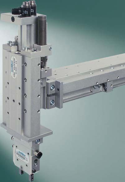
4 170 COMPACT UNIVERSAL SLIDES KUS DESCRIPTION The Compact Universal Slide KUS has a robust design with very high rigidity and a long life. At strokes of min. 20 mm to max. 2 mm, the maximum installation mass is 10 kg. In three sizes with piston diameters from 16 to 25 mm, four stroke lengths are available.

.")


5 171 Ball bearings Stop adjustment Cage for ball synchronization. Adjustable end stops (maximum absorption). Adjustable end stops (minimum absorption). Adjustment of the absorption screw. The high rigidity is achieved by ball bearings with a gothic profile. Ball synchronization is ensured by means of a cage with integrated lubricant reservoir. Hydraulic shock absorbers act as end stops. The absorption characteristics can be adapted to the application, guaranteeing an optimal cycle time. Both end stops are continuously adjustable by 20 or mm, depending on the size.


6 172 Proximity switch for retracted position. Proximity switch for extended position. Air connections Dovetail mount and fixing bores. Compensating spring The two end positions can be detected with two inductive proximity switches. In the case of a stroke adjustment, the proximity switches don t need to be adjusted. Pluggable air connections with adjustable exhaust throttles at the back of the slide ensure optimum accessibility. For maximum installation flexibility, the slide has both Quick-Set dovetail mounts, threads and positioning holes on three sides. For vertical use, a compensating spring (special accessories, page 186) is available, which also ensures uniform movement and an optimum cycle time in vertical operation at maximum load.

7 173 COMPACT UNIVERSAL SLIDES KUS Three sizes with piston diameter of 16, 20 and 25 mm. SCOPE OF DELIVERY Compact Universal Slide with two hydraulic shock absorbers, two integrated holders for inductive proximity switches, two exhaust throttles with plug-type connection and a comprehensive operating instruction. SUITABLE ACCESSORIES Special accessories page 186 Accessories from page 302 (see also assembly instructions from page 176) Quick-Set from page 338
8 17 COMPACT UNIVERSAL SLIDES KUS CALCULATION PRINCIPLES The load values given in the technical data are maximum values for a single load. For the combined loads occurring in practice, the following calculations are applicable: Lx Kx Mz My Lz Mx Fy Fz Ly Fx LOAD CALCULATIONS a) Dynamic loading for horizontal use M x = m g L y M y = m (g (L x K x) + 25 L z) M z = m 25 L y Combined dynamic loading for horizontal use: M y M y max M x + M B = z <_ 1 (M x + M z ) max b) Dynamic loading for vertical use M y = m (g + 25) L z M z = m (g + 25) L y Combined dynamic loading for vertical use: M y M y max M z M z max B = <_ 1
9 175 c) Static loading M 0x = (F y L z + F z L y ) M 0y = (F x L z + F z (L x K x )) M 0z = (F x L y + F y (L x K x )) Combined static loading: M 0x M 0y M 0z B 0 = <_ 1 M 0x max M 0y max M 0z max B, B 0 : Load factor: Must not exceed the value 1! M i, M 0i: Existing moments [Nm] M i max, M 0i max : Max. permissible moments [Nm] (see table) m: Additional mass [kg] L x, L y, L z : Center of gravity distance of the moving mass or distance of acting force [mm] F x, F y, F z : Forces acting [N], max. value see «technical data» from page 180 K x : Constant according to table [mm] g: Acceleration due to gravity (9.81 m/s 2 ) Horizontal use Vertical use Static K x M y max (M x +M z ) max M y max M z max M 0x max M 0y max M 0z max [mm] [Nm] [Nm] [Nm] [Nm] [Nm] [Nm] [Nm] KUS SD KUS-16--SD KUS SD KUS SD KUS-20--SD KUS SD KUS SD KUS SD KUS SD KUS SD KUS SD KUS-25-2-SD ! When a projecting load (direction L z ) is installed on the end plate, it is essential to provide additional fixing on the slide to prevent oscillations (see assembly instructions page 176).
10 176 ASSEMBLY INSTRUCTIONS When installing a projecting load (L z direction) on the end plate, it is essential to provide additional fixing on the slide to prevent vibrations. Fixings of this type can be realized simply and quickly by using Quick- Set elements. e.g. inserter with revolver head: A KW- bracket with two SLL-55- clamping elements is used as an additional fixing element for the vertical KUS. SLL-55- KW- KUS KUS SLL-55- Inductive proximity switches: The inductive proximity switch to be installed must fulfill the following conditions: Sensing distance: 2 mm flush-mountable housing diameter: 6.5 mm minimum housing length (Ø 6.5): 15 mm e. g. MONTECH Ref. No , 50755, or (see accessories). Connecting cable to pluggable proximity switches: With the use of pluggable proximity switches, it is essential to use connecting cables with an angled socket due to the limited space available at the front position detection spot. e. g. MONTECH Ref. No , oder (see accessories).
11 177 DEFORMATIONS DEFINITION OF LOADS Fz fy Fy fz DEFORMATION DIAGRAMS fz [mm] KUS KUS fy [mm] KUS KUS-16- KUS KUS KUS KUS-16- KUS Fz [N] Fy [N] fz [mm] KUS KUS fy [mm] KUS KUS KUS KUS KUS KUS KUS Fz [N] Fy [N] fz [mm] KUS KUS fy [mm] KUS KUS KUS KUS-25-2 KUS KUS KUS Fz [N] Fy [N]
12 178 FORCE DIAGRAMS for KUS with installation kit for compensating spring KUS-16 Retraction pressure [bar] Position [mm] KUS KUS-16- Extension force [N] KUS KUS KUS KUS KUS-16- KUS Retraction force [N] Extension pressure [bar] Compen. spring tension q [mm] (see dimensions) KUS-20 Retraction pressure [bar] Position [mm] KUS-20- Extension force [N] KUS KUS KUS KUS KUS KUS KUS Retraction force [N] Extension pressure [bar] Compen. spring tension q [mm] (see dimensions) KUS-25 Position [mm] KUS Retraction pressure [bar] Extension force [N] KUS KUS KUS-25-2 KUS-25-2 KUS KUS KUS Retraction force [N] Extension pressure [bar] Compen. spring tension q [mm] (see dimensions)
13 179 EXAMPLE TO FORCE DIAGRAM Given: Searched: KUS with installation kit for compensating spring Stroke: 70 mm (vertical, moving downwards) Pressure: 5 bar Additional mass: 6 kg Retraction force in retracted state with compensating spring tension q = 19 mm Extension force in retracted state with compensating spring tension q = 19 mm Retraction force in extended state with compensating spring tension q = 19 mm Extension force in extended state with compensating spring tension q = 19 mm Retraction force in retracted state, without pressure, with compensating spring tension q = 19 mm Retraction force in extended state, without pressure, with compensating spring tension q = 19 mm 1. Determine positions for KUS (point a and point b): for the 70 mm stroke, the extended position is reduced by mm (= max. stop adjustment range per side), position 80 mm results, and additionally the retracted position is reduced by 10 mm ( = 10 mm). From points a and b, draw the lines 1 and 2 vertically downwards. 2. Mark compensating spring tension q = 19 mm for KUS (point c) and draw horizontal line 3 to edge of diagram (results in point d). 3. From point d, draw line parallel to the predetermined lines. The point of intersection with line 1 results in point e and the point of intersection with line 2 results in point f.. From point e, draw horizontal line 5 to the left. The point of intersection with extension pressure 5 bar results in point g, the point of intersection with retraction pressure 5 bar results in point h and the point of intersection with retraction pressure 0 bar results in point i. 5. From point g, draw vertical line 6 upwards, results in an extension force in the retracted state of 188 N. Adding the installation mass of 60 N to this results in 28 N. 6. From point h, draw vertical line 7 downwards, resulting in a retraction force in the retracted state of 19 N. Subtracting the installation mass of 60 N from this results in 13 N. 7. From point i, draw vertical line 8 downwards, results in a retraction force at atmospheric pressure in the retracted state of 20 N, i.e. the installation mass of 60 N is not held in the upper end position at loss of pressure. 8. From point f, draw horizontal line 9 to the left. The point of intersection with extension pressure 5 bar results in point k, the point of intersection with retraction pressure 5 bar results in point l and the point of intersection with retraction pressure 0 bar results in point m. 9. From point k, draw vertical line 10 upwards, results in an extension force in the extended state of 161 N. Adding the installation mass of 60 N to this results in 221 N. 10. From point l, draw vertical line 11 downwards, results in a retraction force in the extended state of 222 N. Subtracting the installation mass of 60 N from this results in 162 N. 11. From point m, draw line 12 downwards, results in a retraction force at atmospheric pressure in the extended state of 7 N, i. e. the installation mass of 60 N is not retracted from the lower end position at loss of pressure. Position [mm] Retraction pressure [bar] Extension force [N] KUS a b KUS KUS KUS-25-2 i h g e 2 8 m f KUS-25-2 KUS KUS KUS l Retraction force [N] k Extension pressure [bar] d 3 c Compen. spring tension q [mm] (see dimensions)
14 180 COMPACT UNIVERSAL SLIDES KUS SD 1) KUS SD KUS-16--SD KUS SD KUS SD Stroke (min./max.) [mm] 5/20 5/ 20/60 /80 Adjustment range for stops (per side) [mm] Piston diameter [mm] Piston-rod diameter [mm] perm. additional mass horiz. m h max [kg] perm. additional mass vert. m v max 2) [kg] max. static moment M 0x max 3) [Nm] max. static moment M 0y max 3) [Nm] max. static moment M 0z max 3) [Nm] max. static force (at 5 bar) F x max 3) [N] max. static force F y max 3) [N] max. static force F z max 3) [N] Weight [kg] Operating pressure [bar] 3 6 Operating medium oiled or unoiled air, filtered to 5 µm, dew point < 6 C End stop absorption hydraulic shock-absorbers Repeatability ) [mm] < 0.01 Check of end position 5) inductive proximity switches Pneumatic connection hose-ø mm Speed regulation adjustable exhaust valves Noise level 6) [dba] < 6 Ambient: Temperature [ C] Rel. humidity < 95% (without condensation) Air purity normal workshop atmosphere Guaranty period 2 years from the date of delivery Mounting position 2) any Material aluminum, steel 1) Designation: KUS-piston diameter-stroke-shock absorber 2) For vertical applications, use compensating spring (see special accessories page 186: Installation kits for compensating spring) 3) See load calculations page 17 ) Scatter of the end positions for 100 successive strokes, conditions as for 6) 5) See assembly instructions page 176 and accessories page 302 6) Measured at 5 bar, maximum stroke horizontal, with m = m h max, throttled (approach end positions without impact) TRAVEL TIME DIAGRAM m [kg] Stroke horizontal [mm] Stroke vertical [mm] horizontal vertical downwards (move out) vertical upwards (move in) t [s] p = 5 bar Vertical operation with compensating spring (with m = 0 kg untensioned, with m = m v max fully tensioned)
15 181 M 6 deep ØH8 7 deep Opening for proximity switch nx M 6 deep 39 d Opening for proximity switch a nx A A-A Air connection ØH8 7 deep M 6 deep ØH8 7 deep 10 b max. c A With installation kit for compensating spring max. q 35 a b c d n q KUS SD KUS-16--SD KUS SD KUS SD Ref. No. KUS SD 515 KUS-16--SD 5151 KUS SD 5152 KUS SD 5153
16 182 COMPACT UNIVERSAL SLIDES KUS SD 1) KUS-20--SD KUS SD KUS SD KUS SD Stroke (min./max.) [mm] 10/ 10/80 /120 80/160 Adjustment range for stops (per side) [mm] Piston diameter [mm] Piston-rod diameter [mm] perm. additional mass horiz. m h max [kg] perm. additional mass vert. m v max 2) [kg] max. static moment M 0x max 3) [Nm] max. static moment M 0y max 3) [Nm] max. static moment M 0z max 3) [Nm] max. static force (at 5 bar) F x max 3) [N] max. static force F y max 3) [N] max. static force F z max 3) [N] Weight [kg] Operating pressure [bar] 3 6 Operating medium oiled or unoiled air, filtered to 5 µm, dew point < 6 C End stop absorption hydraulic shock-absorbers Repeatability ) [mm] < 0.01 Check of end position 5) inductive proximity switches Pneumatic connection hose-ø 6 mm Speed regulation adjustable exhaust valves Noise level 6) [dba] < 6 Ambient: Temperature [ C] Rel. humidity < 95% (without condensation) Air purity normal workshop atmosphere Guaranty period 2 years from the date of delivery Mounting position 2) any Material aluminum, steel 1) Designation: KUS-piston diameter-stroke-shock absorber 2) For vertical applications, use compensating spring (see special accessories page 186: Installation kits for compensating spring) 3) See load calculations page 17 ) Scatter of the end positions for 100 successive strokes, conditions as for 6) 5) See assembly instructions page 176 and accessories page 302 6) Measured at 5 bar, maximum stroke horizontal, with m = m h max, throttled (approach end positions without impact) TRAVEL TIME DIAGRAM m [kg] Stroke horizontal [mm] Stroke vertical [mm] horizontal vertical downwards (move out) vertikal upwards (move in) t [s] p = 5 bar Vertical operation with compensating spring (with m = 0 kg untensioned, with m = m v max fully tensioned)
17 183 M 6.5 deep ØH8 7 deep 30 Opening for proximity switch nx50 M 6 deep 5 Air connection d Opening for proximity switch ØH8 7 deep A-A a 25 nx50 25 A M 6.5 deep ØH8 7 deep 10 b A max. c With installation kit for compensating spring max. q 39 a b c d n q KUS-20--SD KUS SD KUS SD KUS SD Ref. No. KUS-20--SD 515 KUS SD 5155 KUS SD 5156 KUS SD 5157
18 18 COMPACT UNIVERSAL SLIDES KUS SD 1) KUS SD KUS SD KUS SD KUS-25-2-SD Stroke (min./max.) [mm] 10/60 / / /2 Adjustment range for stops (per side) [mm] Piston diameter [mm] Piston-rod diameter [mm] perm. additional mass horiz. m h max [kg] perm. additional mass vert. m v max 2) [kg] max. static moment M 0x max 3) [Nm] max. static moment M 0y max 3) [Nm] max. static moment M 0z max 3) [Nm] max. static force (at 5 bar) F x max 3) [N] max. static force F y max 3) [N] max. static force F z max 3) [N] Weight [kg] Operating pressure [bar] 3 6 Operating medium oiled or unoiled air, filtered to 5 µm, dew point < 6 C End stop absorption hydraulic shock-absorbers Repeatability ) [mm] < 0.01 Check of end position 5) inductive proximity switches Pneumatic connection hose-ø 6 mm Speed regulation adjustable exhaust valves Noise level 6) [dba] < 6 Ambient: Temperature [ C] Rel. humidity < 95% (without condensation) Air purity normal workshop atmosphere Guaranty period 2 years from the date of delivery Mounting position 2) any Material aluminum, steel 1) Designation: KUS-piston diameter-stroke-shock absorber 2) For vertical applications, use compensating spring (see special accessories page 186: Installation kits for compensating spring) 3) See load calculations page 17 ) Scatter of the end positions for 100 successive strokes, conditions as for 6) 5) See assembly instructions page 176 and accessories page 302 6) Measured at 5 bar, maximum stroke horizontal, with m = m h max, throttled (approach end positions without impact) TRAVEL TIME DIAGRAM m [kg] t [s] Stroke horizontal [mm] Stroke vertical [mm] horizontal vertical downwards (move out) vertikal upwards (move in) p = 5 bar Vertical operation with compensating spring (with m = 0 kg untensioned, with m = m v max fully tensioned)
19 185 M5 8 deep Ø5H8 7 deep 30 Opening for proximity switch nx100 M5 8 deep d Opening for proximity switch a nx A A-A Air connection Ø5H8 7 deep 5 M5 8 deep Ø5H8 8 deep 1 b max. c A With installation kit for compensating spring max. q 5.5 a b c d n q KUS SD KUS SD KUS SD KUS-25-2-SD Ref. No. KUS SD 5158 KUS SD 5159 KUS SD KUS-25-2-SD 51551
20 186 SPECIAL ACCESSORIES KUS INSTALLATION KITS FOR COMPENSATING SPRING Tension spring with clamping bolt and two hexagon nuts for installation for vertical application: Ref. No. Installation kit for compensating spring to KUS SD Installation kit for compensating spring to KUS-16--SD Installation kit for compensating spring to KUS SD Installation kit for compensating spring to KUS SD 5163 Installation kit for compensating spring to KUS-20--SD Installation kit for compensating spring to KUS SD Installation kit for compensating spring to KUS SD Installation kit for compensating spring to KUS SD Installation kit for compensating spring to KUS SD Installation kit for compensating spring to KUS SD 516 Installation kit for compensating spring to KUS SD 5161 Installation kit for compensating spring to KUS-25-2-SD 5162
21
22 188 ESCAPEMENT VS VS-30 VS-60 Stroke (min./max.) [mm] 0/30 25/60 Piston diameter [mm] Piston-rod diameter [mm] 6 6 Force to move in/out at 5 bar [N] Weight [kg] Operating pressure [bar] 8 Operating medium air, oiled or unoiled, filtered to 5 µm, dew point < 6 C Reproducibility 1) [mm] 0.02 Check of end positions 2) hydraulic shock-absorbers Pneumatic connections hose-ø mm Speed regulation adjustable exhaust valves M5 Ambient: Temperature [ C] Rel. humidity < 95% (without condensation) Air purity normal workshop atmosphere Guaranty period 2 years from the date of delivery Maintenance When permanently loaded in the y direction, we recommend oiling the surface of the guide every 2 months Material steel, cast iron, bronze 1) Difference in end positions during 100 successive strokes 2) See accessoris page 302 VS, two sizes SCOPE OF DELIVERY The isolating devices are delivered with two exhaust valves and two plastic sleeves for proximity switches. SUITABLE ACCESSORIES Accessories from page 302 Quick-Set from page 338
23 189 VS M5 (8 deep) Stroke Note: The baseplate contains no mounting holes. These can be drilled by the customer to suit the application. European projection L1 L2 Lmax L3 xadm yadm VS N 50 N VS N 50 N Ref. No. VS VS
24 more than technology MONTECH AG Gewerbestrasse 12, CH-552 Derendingen Fon , Fax
Operating Instructions. Handling Components Grippers GPU / GPUI BA ENGLISH
 Operating Instructions Handling Components Grippers GPU / GPUI BA-100008 ENGLISH Edition: 10/2005 Operating Instructions GPU / GPUI Change index Previous editions: Edition Note Reference number 10/2005
Max. particle size 5 µm. Pressure for determining piston forces. Materials:
 Rodless cylinders Rodless cylinder 1 Working pressure min./max. 2 bar / 8 bar Ambient temperature min./max. -10 C / +60 C Medium Compressed air Max. particle size 5 µm Oil content of compressed air 0 mg/m³
TRANSFER SYSTEM LTE. more than technology
 TRANSFER SYSTEM LTE more than technology CUSTOMIZED SOLUTIONS Automotive Automotive Supplier Automotive Supplier Electronic Electronic Electronic Airport Cosmetic Cosmetic Cosmetic Medical Medical Pharmaceutical
OPERATING INSTRUCTIONS UNLOADING CONVEYOR
 OPERATING INSTRUCTIONS UNLOADING CONVEYOR SOLTB-E BA-100103 English, Edition 03/2010 Table of Contents 1. Important Information 2 1.1. EU Declaration of Conformity (pursuant to MRL Appendix II) 2 1.2.
Max. particle size 5 µm. Pressure for determining piston forces Repetitive precision. Polyurethane
 Piston rod cylinders Guide cylinders 1 Ambient temperature min./max. +0 C / +60 C edium Compressed air ax. particle size 5 µm Oil content of compressed air 0 mg/m³ - 1 mg/m³ Pressure for determining piston
OPERATING INSTRUCTIONS
 OPERATING INSTRUCTIONS Handling Components SERVOLINE Servo Horizontal Axis SHA-340 Mechanical Part 507901 ENGLISH Edition: 05/2005 Change index Editions issued so far: Edition Comments Order number 08/2002
Number of fingers 2. Max. particle size 5 µm. Pressure for determining forces
 Bosch Rexroth AG Pneumatics Version Parallel Number of fingers 2 Grip tolerance 0,02 mm Lubrication gripping elements Lubricated for life 00117208 Ambient temperature min./max. +5 C / +60 C Medium Compressed
124
 124 www.danahermotion.com Linear Units Linear Rod Units VarioLine, Movotrak Linear units with rod Perfect for hydraulics and pneumatics replacement Load up to 40 000 N High accuracy ball screw drive High
A5 BELT-DRIVEN RODLESS ELECTRIC AXIS, SERIES ELEKTRO BK
 BELT-DRIVEN RODLESS ELECTRIC AXIS, SERIES ELEKTRO BK Belt-driven rodless electric axis with a V-Lock interface. The structure features an extremely lightweight yet high-strength anodised aluminium extruded
110
 110 www.danahermotion.com Linear Units Linear Lifting Units SpeedLine, Movo Z Developed for lifting applications Telescopic models available Models with ball screw or belt drive Load up to 750 kg High
ELECTRIC AXIS ELEKTRO SVAK SERIES ACTUATORS
 ELECTRIC AXIS ELEKTRO SVAK SERIES 1 ELECTRIC AXIS ELEKTRO SVAK SERIES This belt-driven rodless electric actuator is characterised by the fact that the motor and reducer unit is integral with the carriage,
Rodless Pneumatic Cylinders Series OSP-P
 Rodless Pneumatic Cylinders Series OSP-P System Concepts & Components... 2-5 Technical Data... 7-9 Dimensions... 10-15 Active rakes... 16-19 Accessories (Mounts & Supports)... 20-29 Ordering Information...30
Max. particle size 5 µm. Pressure for determining piston forces. Materials:
 1 Working pressure min./max. 2 bar / 8 bar Ambient temperature min./max. -10 C / +60 C Medium Compressed air Max. particle size 5 µm Oil content of compressed air 0 mg/m³ - 1 mg/m³ Pressure for determining
SERIES RTC RODLESS CYLINDERS PNEUMATIC SHUTTLE TYPE
 SERIES RTC RODLESS CYLINDERS PNEUMATIC SHUTTLE TYPE Series RTC Rodless Cylinder Pneumatic automation building block Series RTC (Rodless Thrust Cylinder)-High performance shuttle type rodless cylinders
ORIGA Pneumatic Linear Drives OSP-L
 ORIGA Pneumatic Linear Drives OSP-L Very long lifetime and lowest leakage A NEW Modular Linear Drive System With this second generation linear drive Parker Origa offers design engineers complete flexibility.
USER MANUAL HANDLING COMPONENTS. Rotary Units DAP-1 / DAPI-1
 USER MANUAL HANDLING COMPONENTS Rotary Units DAP-1 / DAPI-1 BA-100010 english, Edition 01/2007 Table of contents 1. Important information 3 1.1. Operational discharge 3 1.2. Declaration of EU conformance
PARALLEL INDEX DRIVES TP Series
 PARALLEL INDEX DRIVES TP Series Calculations J = moment of inertia Application examples Direct driven belt/chain = M B + M B M B = c a n 2π n x t² M R = µ g R m = M B + M R + (M ST )* M ST = m g R M AN
Linear Drive with Toothed Belt Series OSP-E..B. Contents Description Overview Technical Data Dimensions Order Instructions 46
 Linear Drive with Toothed Belt Contents Description Page Overview 35-38 Technical Data 39-43 Dimensions 44-45 Order Instructions 46 35 The System Concept ELECTRIC LINEAR DRIVE FOR POINT-TO-POINT APPLICATIONS
Mini slides SLT/SLS/SLF
 Mini slides SLT/SLS/SLF Mini slides SLT/SLS/SLF Key features General information Double-acting drives Precise and rigid guide Versatile air connections Sensors can be integrated Highly flexible thanks
96
 96 www.danahermotion.com Linear Units Linear Units with Belt Drive and Wheel Guide SpeedLine, ForceLine Velocity Noise Acceleration Maintenance Repeatability Cost Force Guide Robustness Load Torque Stiffness
ELECTRIC ACTUATOR - RODLESS ELEKTRO SK SERIES ACTUATORS
 ELECTRIC ACTUATOR - RODLESS ELEKTRO SK SERIES 1 ELECTRIC AXIS - RODLESS ELEKTRO SK SERIES Electric axis without screw piston rod, with V-Lock interface. The cylinder frame is made of anodized extruded
Linear Units with Belt Drive and Slide Guide
 84 www.danahermotion.com Linear Units Linear Units with Belt Drive and Slide Guide Movopart Velocity Noise Acceleration Maintenance Repeatability Cost Force Guide Robustness Load Torque Stiffness Typical
Roller guide actuator/guides - SQ /SQZ
 Roller guide actuator/guides - SQ /SQZ Timing-belt unit with optimum connecting options due to slots in guide profile/carriage Fixing slots 9Easy 9 fixing of linear actuator 9Simple 9 connection of accessories
LAP4, LAP8. Pneumatic linear drive sizes 4 and 8
 Pneumatic linear drive sizes 4 and Torsional and bending resistant profiles T-slots in the outer profile enable individual mounting options Adjustable guiding system (LAP4) Precise linear roller guiding
OPERATING INSTRUCTIONS
 Handling Components OPERATING INSTRUCTIONS Linear Unit: LEP Edition: 506 168 30.7.03 Contents: Important information EC Declaration of Conformity (EC)...1 Scope of these instructions...2 Technical data...3
Ball Rail Systems RE / The Drive & Control Company
 Ball Rail Systems RE 82 202/2002-12 The Drive & Control Company Rexroth Linear Motion Technology Ball Rail Systems Roller Rail Systems Standard Ball Rail Systems Super Ball Rail Systems Ball Rail Systems
Guided drives DFM/DFM-B
 Guided drives DFM/DFM-B q/w Worldwide: Superb: Easy: Festo core product range Covers 80% of your automation tasks Always in stock Festo quality at an attractive price Reduces procurement and storing complexity
Linear Drive with Toothed Belt and Integrated Guide with Recirculating Ball Bearing Guide with Roller Guide Series OSP-E..BHD
 Linear Drive with and Integrated Guide with Recirculating Ball Bearing Guide with Roller Guide Contents Description Page Overview 11-14 Version with Recirculating Ball Bearing Guide Technical Data 15-17
PGN-plus. Universal Gripper Universal 2-finger parallel gripper with large gripping force and high maximum moments thanks to multi-tooth guidance.
 PGN-plus Sizes 40 380 Weight 0.08 kg 39.5 kg Gripping force 123 N 21150 N Stroke per finger 2 mm 45 mm Workpiece weight 0.62 kg 80.5 kg Application example Pick-and-place unit for light to medium-weight
Linear drives SLG, flat design
 Features General information Piston 8, 12 and 18 Stroke lengths of 100 900 mm Two cushioning types selectable: Elastic cushioning Shock absorbers Direct mounting via centering holes Extremely flat design
Linear drives DGC Key features
 Linear drives DGC Linear drives DGC Key features General information Compact fitting length relative to stroke Loads and devices can be directly mounted on the slide Three types of cushioning available:
PWG. Application example. Pneumatic 2-Finger Angular Gripper Universal Gripper. Sizes. Gripping moment 6.44 Nm Nm. Weight 0.33 kg 16.
 PWG Sizes 65 230 Weight 0.33 kg 16.3 kg Gripping moment 6.44 Nm 934.2 Nm Angle per jaw 20 Workpiece weight 0.8 kg 35.8 kg Application example Rotary feed unit for shafts 2-Finger Angular Gripper PWG Rotary
Guided drives DFM/DFM-B
 Guided drives DFM/DFM-B q/w Worldwide: Superb: Easy: Festo core product range Covers 80% of your automation tasks Always in stock Festo quality at an attractive price Reduces procurement and storing complexity
USER MANUAL HANDLING COMPONENTS. Rotary Units DAP-2 / DAPI-2
 USER MANUAL HANDLING COMPONENTS Rotary Units DAP-2 / DAPI-2 BA-100011 english, Edition 03/2006 Table of contents 1. Important information 3 1.1. Operational discharge 3 1.2. Declaration of EU conformance
WIESEL POWERLine and WIESEL DYNALine with ball screw drive Innovative solutions, down to the very last detail.
 WIESEL POWERLine and WIESEL DYNALine with ball screw drive Innovative solutions, down to the very last detail. WIESEL POWERLine WM40 The linear drive unit for miniaturized applications. High performance
Roller guide actuators - SQ ZST
 Roller guide actuators - SQ ZST Rack and pinion with fixed carriage, also for larger travels up to 30 m RK Standard motor 9Choice 9 of motor and motor adaptor plate to suit your requirements 9 9Simple
EMC-HD. C 01_2 Subheadline_15pt/7.2mm
 C Electromechanical 01_1 Headline_36pt/14.4mm Cylinder EMC-HD C 01_2 Subheadline_15pt/7.2mm 2 Elektromechanischer Zylinder EMC-HD Short product name Example: EMC 085 HD 1 System = ElectroMechanical Cylinder
Parallel Grippers. Body One piece anodized aluminum body
 Catalog 19-2/US Features Rack and Pinion Rack and pinion drive mechanism provides synchronous motion. Body One piece anodized aluminum body Bushings Four composite bushings provide the support needed for
SNR, YOUR GUIDE TO LINEAR MODULES
 SNR, YOUR GUIDE TO LINEAR MODULES A bearing manufacturer known across the world For almost a century NTN-SNR has been focusing on the development, design and manufacture of bearings. Today NTN-SNR has
RODLESS CYLINDER - PARKER ORIGA CURSOR
 ORIGA SYSTEM PERMANENT EXTERNAL SHEET INTERNAL SHEET CURSOR CUSHIONING SCREW BARREL PISTON END CAP The exclusive principle ORIGA solves in a simple way every problem about linear transaltion. This brilliant
Mini slides SLT/SLS/SLF
 Mini slides SLT/SLS/SLF Mini slides SLT/SLS/SLF Key features General information Double-acting drives Precise and rigid guide Versatile air connections Sensors can be integrated Highly flexible thanks
USER MANUAL ELECTRICAL ROTARY UNIT DAE-60. Mechanical Part
 USER MANUAL ELECTRICAL ROTARY UNIT DAE-60 Mechanical Part BA-100074 Starting from serial number 430044 English, Edition 02/2008 Contents 1. Important information 3 1.1. Introduction 3 1.2. EU conformance
M/46800/M, M/46800/HM, M/46800/PM
 External guides for heavy loads over long distances Rigid, reinforced aluminium profile provides greater load support T-slots in the outer profile enable individual mounting options Precision guidance
OSPE..BHD Belt-Driven Actuators
 OSPE..BHD Belt-Driven Actuators Actuators for High-Speed, Long Travel, Heavy Duty Applications The OSPE..BHD is the highest capacity belt-driven actuator in the OSPE family. The integrated ball bearing
Linear Drive with Ball Screw Drive Series OSP-E..SB
 Linear Drive with Ball Screw Drive Series OSP-E..SB Contents Description Data Sheet No. Page Overview 1.30.001E 47-50 Technical Data 1.30.002E-1 to 5 51-55 Dimensions 1.30.002E-6, -7 56-57 Order instructions
PZN-plus Application example Pneumatic 3-Finger Centric Gripper Universal Gripper Stroke per finger 2 mm 35 mm
 PZN-plus Sizes 40 300 Weight 0.13 kg 46 kg Gripping force 255 N 35500 N Stroke per finger 2 mm 35 mm Workpiece weight 1.3 kg 127.5 kg Application example Insertion tool for assembling small to mediumsized
Profile guide/actuator - RK Compact
 Profile guide/actuator - RK Compact Slimline short-stroke linear actuator for hand adjustment with excellent price-performance ratio Control knob with vernier Simple adjustment of carriage Backlash of
Mini slides DGSL. Festo core product range Covers 80% of your automation tasks
 q/w Worldwide: Superb: Easy: Festo core product range Covers 80% of your automation tasks Always in stock Festo quality at an attractive price Reduces procurement and storing complexity qready for dispatch
Gripping rotary modules.
 Gripping rotary modules Gripping rotary modules GRIPPING ROTARY MODULES Series Size Page Gripping rotary modules RP 314 RP 1212 318 RP 1216 322 RP 1520 326 RP 2120 330 RP 2128 334 RC 338 RC 1212 342 RC
Modular. Robust. Flexible. SWS Quick-change system
 SWS Modular. Robust. Flexible. SWS Quick-change system Pneumatic tool changing system with patented locking system. Field of Application C an be used wherever short changeover times between a handling
P1Z Series. Magnetically Coupled Rodless Air Cylinders Contents
 Magnetically Coupled Rodless Air Cylinders Contents Basic Version Features... 15 Ordering Information... 151 Specifications... 152 Technical Data... 153 Dimensions... 154 Mountings... 155 uided Version
PC-Series Precision Linear Actuators. Optimize Your Machine and Save Energy With Reliable, High Performance, Compact Actuators
 PC-Series Precision Linear Actuators Optimize Your Machine and Save Energy With Reliable, High Performance, Compact Actuators Make the Change to Electric Enjoy superior performance and save time and energy
Mini slides SLTE, electric
 Key features Range of applications Special features The electric mini slide SLTE is ideal for use in automation applications where controlled end-position cushioning (gentle stopping), constant travel
PGN-plus. Universal Gripper Universal 2-finger parallel gripper with large gripping force and high maximum moments thanks to multi-tooth guidance.
 PGN-plus Sizes 40 380 Weight 0.08 kg 39.5 kg Gripping force 123 N 21150 N Stroke per finger 2 mm 45 mm Workpiece weight 0.62 kg 80.5 kg Application example Pick-and-place unit for light to medium-weight
MGX. 2-jaw parallel self-centering pneumatic gripper series MGX. Parallel grippers. Pinze parallele MGX
 Pinze parallele MGX Parallel grippers MGX 2-jaw parallel self-centering pneumatic gripper series MGX Flat profile. Robust guide. High gripping force. Small weight and dimensions. High dimensional accuracy.
Ball rail actuator/guide - RK DuoLine Z/R
 Ball rail actuator/guide - RK DuoLine Z/R All-round talent with protected guide system Fixing slots in the guide profile and carriage 9Simple 9 connection of accessories 9Excellent 9 fixing options for
GSM. Modular Design. Versions of the series. Type GSM. Gripper type P Z W R. Size. {} AS IS without O.D. clamping I.D. clamping
 GSM Pneumatic Gripper-Swivel System Modular Design Versions of the series Type GSM Gripper type P Z W R Size 32 40 50 64 30 38 45 16 20 25 32 40 16 20 25 32 40 Gripping force safety device {} AS IS without
Toothed belt axes DGE
 Toothed belt axes DGE Toothed belt axes DGE Key features At a glance Precision, rigid guide Highly adaptable, thanks to wide choice of mounting and attachment options Wide range of options for attaching
ROTARY MODULES. Rotary modules
 Rotary modules Rotary modules ROTARY MODULES Series Size Page Rotary modules RM swivel unit 156 RM 08 160 RM 10 162 RM 12 164 RM 15 168 RM 21 172 RM rotor 176 RM 50 180 RM 110 182 RM 200 184 RM 310 186
Cam roller guide LF12S complete axis
 Y -16 MGE. Linear guides Z Mz Cam roller guide LF1S complete axis X Mx M y [mm] B [mm] Fully assembled cam roller guide Stroke and trolley length can be individually selected Rail profile screwed onto
TELESCOPIC RAILS HARDENED TELESCOPIC RAILS FOR HIGHLY DYNAMIC APPLICATIONS 7.1 PRODUCT OVERVIEW 7.2 PART EXTENSIONS 7.
 7 TELESCOPIC RAILS HARDENED TELESCOPIC RAILS FOR HIGHLY DYNAMIC APPLICATIONS PAGE 106 PAGE 116 PAGE 120 PAGE 126 7.1 PRODUCT OVERVIEW 7.2 PART EXTENSIONS 7.3 FULL EXTENSIONS 7.4 LINEAR GUIDES 105 PRODUCT
Rodless cylinders Rodless cylinders Series RTC. Brochure
 Series RTC Brochure Bosch Rexroth AG Pneumatics Series RTC Rodless cylinder, Series RTC-BV Ø 16-80 mm; double-acting; with magnetic piston; integrated guide; Basic Version; cushioning: pneumatic, adjustable
Linear drives DGC. Festo core product range Covers 80% of your automation tasks
 Linear drives DGC q/w Worldwide: Superb: Easy: Festo core product range Covers 80% of your automation tasks Always in stock Festo quality at an attractive price Reduces procurement and storing complexity
RE-CIRCULATING BALL BEARING LINEAR GUIDES (SERIES LP)
") RE-CIRCULATING BALL BEARING (SERIES ) Patented re-circulating ball bearing guide system. Several T-nut mounting options. Optional mounting accessory kits are available. More than one carrier per rail can
RE-CIRCULATING BALL BEARING (SERIES ) Patented re-circulating ball bearing guide system. Several T-nut mounting options. Optional mounting accessory kits are available. More than one carrier per rail can
MULTI SLIDERS CONTENTS
 CAD drawing data catalog is available. ACTUATORS GENERAL CATALOG CONTENTS Features 923 Handling Instructions and Precautions 925 Specifications 929 Order Codes 930 Inner Construction 931 Dimensions 932
TELESCOPIC-LINE. Semi-telescopic-rail LST. Telescopic-rail LSE. Linear guides with ball-cage LSS
 TELESCOPIC-LINE Semi-telescopic-rail LST Telescopic-rail LSE Linear guides with ball-cage LSS 1 Ball rails LSS, LST and LSE The ball rails produced by Nadella are very compact and flexible products. Made
Flexible. Fast. Reliable. ELM Compact Linear Module
 ELM Flexible. Fast. Reliable. ELM Compact Linear Module With linear direct drive and profiled rail guide with integrated measuring system for position detection and temperature monitoring. Field of Application
Lifting modules HM HM 10 - HM 25
 Table of contents: HM Lifting modules HM HM 0 - HM Lifting modules HM HM 0 HM HM 0 Page 0 0 0 Handling technology HT Components linear afag.com afag.com Handling technology HT Components linear Lifting
Maximum force range from 15 kn to 220 kn
 SCHMIDT HydroPneumaticPress Maximum force range from 1 kn to 220 kn The SCHMIDT HydroPneumaticPress range consists of a modular system suitable for transforming, joining and assembling optimally within
MINIDRIVE CONVEYOR KTB. more than technology
 MINIDRIVE CONVEYOR KTB more than technology CUSTOMIZED SOLUTIONS ssembly Watch industry Electronics industry Construction industry Mechanical engineering Plastics industry Printing industry utomotive suppliers
WIESEL SPEEDLine WHZ80 with roller guideway and AT toothed belt
 WIESEL WHZ80 with roller guideway and AT toothed belt All figures shown in millimeters. Note: Mounted wipers on request. The use of a long power bridge increases the total length. Technical data Linear
Linear Motion. Optimized.
 Thomson - Linear Motion. Optimized. Linear Motion. Optimized. Often the ideal design solution is not about finding the fastest, sturdiest, most accurate or even the least expensive option. Rather, the
SCHMIDT HydroPneumaticPress
 Maximum orce Range from 1 kn to 220 kn The SCHMIDT HydroPneumaticPress range consists of a modular system suitable for transforming, joining and assembling optimally within the pressing force range 1 220
Vertical Linear Drive with Toothed Belt and Integrated Recirculating Ball Bearing Guide Series OSP-E..BV
 Vertical Linear Drive with and Integrated Recirculating Ball Bearing Guide Series OSP-E..BV Overview...25-28 Technical Data...29-31 Dimensions...32-33 25 Features TOOTHED BELT DRIVE FOR VERTICAL MOVEMENTS
ORIGA SYSTEM PLUS OSP-P
 ORIGA SYSTEM PLUS OSP-P The ORIGINAL rodless pneumatic cylinders A NEW Modular Linear Drive System With this second generation linear drive Parker Origa offers design engineers complete flexibility. The
highlights Double tube linear actuators
 highlights GN 491 with right or left hand thread, single slider 3 Type R1 Right hand thread, single shaft end R2* Right hand thread, two shaft ends L1* Left hand thread, single shaft end L2* Left hand
Linear Actuator with Toothed Belt Series OSP-E..B
 Linear Actuator with Toothed Belt Series OSP-E..B Contents Description Data Sheet No. Page Overview 1.20.001E 21-24 Technical Data 1.20.002E-1 to 5 25-29 Dimensions 1.20.002E-6 30 Order Instructions 1.20.002E-7
RE-CIRCULATING BALL BEARING LINEAR GUIDES (SERIES LM)
") LM RE-CIRCULATING BALL BEARING (SERIES LM) Patented re-circulating ball bearing guide system. Several T-nut mounting options. Optional mounting accessory kits are available. Available in any length up
LM RE-CIRCULATING BALL BEARING (SERIES LM) Patented re-circulating ball bearing guide system. Several T-nut mounting options. Optional mounting accessory kits are available. Available in any length up
ndustr SNR our guide to linear modules
 ndustr SNR our guide to linear modules SNR A bearing manufacturer known across the world For almost a century SNR has been focusing on the development, design and manufacture of bearings. Today SNR has
MTB 42 Belt Driven Linear Actuator
 LINEAR ACTUATOR TECHNOLOGY MT Series MTB Belt Driven Linear Actuator The MT Series offers a number of profile sizes with multiple design configurations to fit almost any application. TECHNICAL DATA features
Standard gripper Series GSP
 Industrial Hydraulics Electric Drives and Controls Linear Motion and Assembly Technologies Pneumatics Service Automation Mobile Hydraulics Standard gripper Series GSP Technical Data Products Series GSP-P
Standard cylinders DDPC, with measured-value transducer DADE
 Features Components for positioning and measuring using the standard cylinder DDPC Measuring with measured-value transducer DADE Positioning with end-position controller SPC11 or controller module CPX-CMAX/-CMPX
Series CP95. Profile Design ISO/VDMA Air Cylinder. Increased kinetic energy absorption. Improved end of stroke cushion capacity
 Profile Design ISO/VDMA Air Cylinder Series CP95 Improved end of stroke cushion capacity Piston rod lurching has been eliminated at the end of stroke positions by means of a floating seal mechanism. Increased
PNCE ELECTRIC CYLINDERS
 ELECTRIC CYLINDERS Every care has been taken to ensure the accuracy of the information contained in this catalogue, but no liability can be accepted for any errors or omissions. We reserve the right to
Linear drives DGP/DGPL
 Linear drives DGP/DGPL Low space requirement High precision and load capacity Reliable service life of up to 40,000 km Specified types in accordance with ATEX directive for potentially explosive atmospheres
Linear drives DGC-HD, with heavy-duty guide
 Linear drives DGC Key features At a glance New heavy-duty design for: Maximum loads and torques thanks to duo rail guide Long service life Ideal as a basic axis for linear gantries and cantilever axes
PRUT series - Rodless cylinder
 series - cylinder Operating specification and Ordering expression Internal structure PRU PRF Theoretical force Bore size mm Action Piston area cm² 2.0 3.1 4.9 8.0 12.5 Unit : kgf Air pressure ( kgf / cm²
Standards ISO Max. particle size 50 µm. Pressure for determining piston forces. Materials: Polyurethane
 Ports: - double-acting with magnetic piston Cushioning: elastic Piston rod: external thread 1 Standards ISO 21287 Compressed air connection Internal thread Working pressure min./max. 1 bar / 10 bar Ambient
PNCE ELECTRIC CYLINDER
 ELECTRIC CYLINDER INDEX Characteristics 1 Structural design 2 How to order 3 Technical data 4 Dimensions 11 Accessories 12 Lubrication position 2 Motor adapter with coupling 2 Motor side drive with timing
Innovation & Excellence. Index. Index. Innovation & Excellence. Introduction. Our Solutions 4-5. MLE / MLZ Series iron core motor
 Index Innovation & Excellence Introduction 3 Our Solutions 4-5 MLE / MLZ Series iron core motor 6-7 MLE 2 Linear Units 8-9 MLE 3 Linear Units 10-11 Index MLE 5 Linear Units MLE 7 Linear Units MLZ 2 Linear
-U- Type discontinued. -H- Note. Available up until Angle grippers HGWC Key features
 Key features At a glance General information The compact and cost-optimised angle gripper consists of a two-part mirrorsymmetrical housing made of die-cast zinc. The force generated by the linear motion
Separators. pneumatic
 Separators pneumatic Table of contents separators VEG-B Order no. Stroke Force in Force in Page [mm] retract [N] extend [N] Product Information 6 VEG10-B 10 30 40 10 VEG14-B 20 65 80 12 VEG15-B 40 65
Actuator Units NEW All-in-one-solution
 Actuator Units NEW All-in-one-solution Axis Servo Motor Amplifier Actuator Units Economy Series ES4 p. 06-07 ES6 p. 08-09 EC3 p. 10-11 EC4 p. 12-13 LM Guide Actuator KR26 p. 16-17 KR33 p. 18-19 Linear
The PReMIeRe of The year
 The PReMIeRe of The year SRU-plus pneumatic universal rotary actuator SRU-plus Pneumatic universal rotary actuator SRU-plus one of the most powerful rotary actuator on the market. a consistent modular
Cam roller guide LF6S complete axis
 Y 1- MGE 1. Linear guides Z Mz Cam roller guide LFS complete axis X Mx M y [mm] B [mm] Fully assembled cam roller guide Stroke and trolley length can be individually selected Rail profile screwed onto
NOMENCLATURE. Optional: V = Viton FKMsealing. RÖHM Z centric gripper Pneumatic. Sizes A = Alternative jaw fixture by tongue and groove
 NOMENCLATURE RZP -A - 100-1 / GA / V RÖHM Z centric gripper Pneumatic A = Alternative jaw fixture by tongue and groove Sizes 64-300 Jaw stroke variant 1 = long stroke 2 = short stroke Optional: spring
ANGULAR PNEUMATIC GRIPPERS 180 SERIES DIRECTCONNECT TM
 ANGULAR PNEUMATIC GRIPPERS 1 SERIES DIRECTCONNECT TM with spring assist DCT-RE Series No Adaptor Plates Required Highly Configurable Modular Construction, Exclusive DIRECTCONNECT TM Technology Full Jaw
SLIDE TABLES CONTENTS
 CAD drawing data catalog is available. ACTUATORS GENERAL CATALOG SLIDE TALES CONTENTS Features 979 Safety Precautions, Handling Instructions and Precautions 981 Specifications 985 Order Codes 986 Inner
Contents. Page. 1. Product description. 2. The AXC line of linear axes. 3. AXLT line of linear tables. AXC and AXS product overview...
 SNR Industry Contents Page 3 1. Product description AXC and AXS product overview... 6-8 Dynamic load ratings of the linear motion systems... 9 Compact modules... 10-11 Linear tables... 12 Telescopic axes...
Rodless Pneumatic Cylinders Series OSP-P
 Rodless Pneumatic Cylinders Series OSP-P Contents Description Data Sheet No. Page Standard Cylinders Overview 1.10.001E 9-13 Technical Data 1.10.002E-1 to 3 15-17 Dimensions 1.10.002E-4 to 9 18-23 Order