New Metro North. Green Line Metro Upgrade Line B NMN-GTW-0003_01
|
|
|
- Alannah Wiggins
- 5 years ago
- Views:
Transcription


1 New Metro North Green Line Metro Upgrade Line B NMN-GTW-0003_01
2 Document Control Information Document Title New Metro North Green Line Metro Upgrade Line B Filename Date Description Doc. No. Rev. Prepared Checked Approved 27/06/2017 DRAFT NMN-GTW PB AF
3 Table of Contents EXECUTIVE SUMMARY... 7 INTRODUCTION Study Scope and Objective Luas Green Line Tie-in Study... 9 EXISTING INFRASTRUCTURE Line B (Ranelagh to Sandyford) Line B1 (Sandyford to Bride s Glen) METRO OPERATING SCENARIOS Scenario 1: 60m LFV Driver Controlled Scenario 2: 60m HFV Fully Automatic Scenario 3: 90m LFV Driver Controlled INFRASTRUCTURE ASSESSMENT Line B (Ranelagh to Sandyford)/Segregation Luas Stop/Platform Modifications Sandyford Depot Implications COST IMPACT ESTIMATE LINE B (RANELAGH TO SANDYFORD) Scenario 1: 60m LFV Driver Controlled Scenario 2: 60m HFV Fully Automatic Scenario 3: 90m LFV Driver Controlled Costs Summary for All Scenarios CONCLUSION APPENDICES APPENDIX 1: LINE B STUDY AREA SCENARIO 3 STOP ANALYSIS APPENDIX 2: LINE B STUDY AREA SCENARIO 3 PLATFORM DRAWINGS APPENDIX 3: LINE B STUDY AREA SCENARIO 2 PLATFORM DRAWINGS Page 3 of 72
4 List of Figures Figure 1: Overall cost estimates for Line B for all scenarios... 7 Figure 2: NMN tie-in point at Ranelagh Figure 3: NMN tie-in in context with Luas Green Line Figure 4: Dunville Avenue Figure 5: Access to Alexandra College Figure 6: St Raphaela s Road junction with Luas at Stillorgan Figure 7: Proposed overpass and elevated stop at Stillorgan Figure 8: Proposed temporary track for maintaining Luas operations during bridge construction Figure 9: Approx. platform edge area to be removed and photo of platform edge Figure 10: Cross-section through typical upgraded stop (Scenario 2) Figure 11: High-floor Copenhagen metro - before and after installation of PSGs Figure 12: Typical arrangement at upgraded stop (Scenario 2) Figure 13: Ranelagh Stop following upgrade (Scenario 2) Figure 14: Dundrum Stop following upgrade (Scenario 2) Figure 15: Sandyford Stop following upgrade (Scenario 2) Figure 16: Ranelagh passenger access Figure 17: Cowper pedestrian passage/crossing Figure 18: Sandyford Stop extension Figure 19: Sandyford Depot capacity and modifications for 60m metro vehicles Figure 20: Sandyford Depot capacity and modifications for 90m metro vehicles Figure 21: Overall cost estimates for Line B for all scenarios List of Tables Table 1: Line B Study Area - Scenario 1 Summary Table 2: Line B Study Area - Scenario 2 Summary Table 3: Line B Study Area - Scenario 3 Summary Page 4 of 72
5 Table 4: Assumptions and Exclusions for Costing Scenario Table 5: Cost Estimate Breakdown Scenario Table 6: Assumptions and Exclusions for Costing Scenario Table 7: Cost Estimate Breakdown Scenario Table 8: Assumptions and Exclusions for Costing Scenario Table 9: Cost Estimate Breakdown Scenario Page 5 of 72
6 Glossary of Terms/Acronyms Term Bored tunnel Cut and cover tunnel/box Engineering link Track interaxis Tunnel portal Segregation Acronym AVLS DCC DKE GLCE GLIU HFV LFV MS NMN NTA PPHPD PSGs TBM TPH TII Definition Underground tunnel, excavated by a Tunnel Boring Machine. A tunnel or box structure where a trench is excavated to the required dimensions and is roofed over with an overhead support system, strong enough to carry the load of what is to be built above. A non-service track connection between two rail systems to allow movement of vehicles between them for maintenance or for stabling in a depot. Where tracks are side-by-side, the track inter-axis is the distance between the centre points of each track. The wider the distance, the more space there is between passing vehicles. The entrance or exit to a tunnel. The interface point between the underground tunnel and the ground level. Metro tracks are fully separated from other traffic and from pedestrians. It is an essential requirement for the running of high frequency metro vehicles. Definition Automatic Vehicle Location System Dublin City Council Dynamic Kinetic Envelope (Luas) Green Line Capacity Enhancement (Luas) Green Line Infrastructure Upgrade High Floor Vehicle Low Floor Vehicle Metro South New Metro North National Transport Authority Passengers per hour, per direction Platform Safety Gates Tunnel Boring Machine Trains per hour Transport Infrastructure Ireland Page 6 of 72
7 EXECUTIVE SUMMARY The extent of upgrades required on the Luas Green Line is wholly dependent on the type of system proposed for New Metro North (NMN); however, at the time of this study, no decision on the type of vehicle or the mode of operation has been made. Therefore, the objective of this Green Line Metro Upgrade study is to estimate the costs and identify the extent of work required to upgrade Line B from Ranelagh to Sandyford for three potential metro operating scenarios, namely: 1. Scenario 1: 60m long low-floor vehicles, operating similar to the current Luas system with minimal additional segregation with the exception of road junctions. 2. Scenario 2: 60m long high-floor vehicles, operating fully automatic and requiring significant infrastructure segregation from road junctions, other vehicles, passengers and pedestrians. 3. Scenario 3: 90m long low-floor vehicles, operating similar to the current Luas system with minimal additional segregation with the exception of road junctions. Figure 1 provides the estimated costs for converting the line section from Ranelagh and Sandyford to a metro standard to the extent required by each of the scenarios. In the event that it is deemed that road segregation is not a requirement for Scenario 1 or 3, estimated costs for each scenario reduce by 20 million. As Scenario 2 involves a fully automated rail system, full segregation from roads and other points of interface with pedestrians and vehicles is an absolute requirement. Figure 1: Overall cost estimates for Line B for all scenarios A large proportion of the additional costs for Scenario 2 arise from the work to extend the platform to 60m, raise the platform heights, install safety gates at platforms and modify access routes to each platform, including foot bridges and additional lifts (as the track cannot be crossed). Page 7 of 72
8 INTRODUCTION The National Transport Authority s (NTA) Fingal/North Dublin Study (June 2015), recommended an optimised Metro North scheme as the preferred public transport solution to service the passenger demand along the corridor between Dublin City Centre, Dublin Airport and Swords. The Government s seven year investment plan titled Building on Recovery: Infrastructure and Capital Investment (October 2015) endorsed this recommendation and included for a new metro project for Dublin, referred to as New Metro North (NMN). The NTA s Transport Strategy for the Greater Dublin Area, (The Strategy) provides a framework for the planning and delivery of transport infrastructure and services in the Greater Dublin Area (GDA) over the next two decades. It has built on the work undertaken in the Fingal/North Dublin Study and undertaken similar studies for all other corridors. In this regard, it provides the context for the integrated transport network within which NMN will operate. The Strategy defines NMN as a high speed, high capacity, high frequency public transport link from the city centre to Dublin Airport and Swords. The city centre section will be underground. As described in the Strategy, it is anticipated that NMN will ultimately tie into Dublin s existing Luas Green Line light rail system, enabling through running of metro trams from Swords to Bride s Glen. The Project Objective for NMN as agreed with the NTA is as follows: To provide a safe, high frequency, high capacity, fast, efficient, fully segregated and sustainable public transport light rail service from the city centre to Dublin Airport and Swords. In delivering this objective, NMN will: Cater for existing and future public transport travel demand along this corridor; Be modern, attractive and accessible to all users; Be designed to integrate appropriately into the existing public realm; Be segregated from other transport modes between Dublin Airport and the City Centre; Contribute to a reduction in urban congestion and the enhancement of the environmental sustainability of the region; Support the continued economic development of the Dublin area and the wider State. Deliver a high quality service with journey-time reliability along the corridor; Be planned, constructed and operated in an environmentally sustainable manner; Support public transport network integration by providing high quality passenger interchange points, which facilitate convenient transfer between public transport services at key locations; Facilitate connection to key trip attractors; and Support the strategy for a strategic Park & Ride Page 8 of 72
9 2.1 Study Scope and Objective The objective of the Luas Green Line Metro Upgrade study is to carry out an engineering feasibility and costing assessment on upgrading the existing Luas Green Line to a metro standard to facilitate the through running of metro services from Swords to Bride s Glen as envisioned in the Strategy. Within the Strategy (Section 5.5.3), Metro South (MS) is described as an upgrading of the existing Luas Green Line to metro standard through the extension of NMN southwards, via a tunnel, to join the Luas Green Line in the Ranelagh area, enabling through running of metro trams from Swords to Bride s Glen. The upgrading of the Luas Green Line to metro standard will ensure that growth along this corridor can be accommodated and, in combination with NMN to Swords, will provide Dublin with a high capacity, high frequency cross-city rail corridor, serving critical destinations at Dublin Airport, Dublin City University, Dublin City Centre and Sandyford directly. The extent of the infrastructure works required to upgrade the current Luas Green Line to a metro standard, wholly depends on the type of metro system proposed to operate on NMN. At the time of this study, no decision on the operating characteristics of NMN has been made; therefore, three likely operating scenarios have been considered for analysis in this study and these are described in detail in Section 3.2. The existing Luas Green Line can be divided into two sections: Line B which runs from Ranelagh to Sandyford and Line B1 which runs from Sandyford to Bride s Glen. The sections differ considerably in terms of their operating environment. Line B runs within the old railway cutting and is largely segregated from its surrounds, other than at three locations (Dunville Avenue / Beechwood Road at Beechwood Stop, access to Alexandra College from Richmond Avenue South at Milltown Stop and St. Raphaela s Road at Stillorgan Stop) where there are at-grade crossings. Line B1 has a far higher level of at-grade running at locations such as Blackthorn Avenue, Ballyogan Road and between Carrickmines and Cherrywood stations; this section of the Luas Green Line will be analysed for impacts in the next revision of this document. The scope of this study includes infrastructure and cost estimates for Line B, but does not cover potential environmental impacts, effects on Luas Green Line services during construction, transport modelling of any scenario, or architectural considerations of proposed solutions. 2.2 Luas Green Line Tie-in Study In January 2016, Transport Infrastructure Ireland (TII) commenced work on the Luas Green Line Tiein Study. The objective of the study was to identify the preferred location and configuration for a tiein between NMN and the existing Luas Green Line, which would ultimately enable through running of metro vehicles from Swords to Bride s Glen. The study was completed in January 2017 and concluded that Option 4(B) - Ranelagh In-line is the preferred tie-in option for NMN. Option 4(B) - Ranelagh In-line is illustrated in Figure 2. The site is located to the rear of No. 2 Grand Parade, Dublin 6. From the north, NMN tunnels will be bored under No. 2 Grand Parade which is a Protected Structure to the vacant lot to the rear of the building where a new metro stop will be located. The tracks will then rise in a cut and cover section, passing under Dartmouth Road and Northbrook Road. Immediately south of Northbrook Road, the track will continue to rise in a retained Page 9 of 72

10 cut along the line of the existing Luas Green Line embankment and then onto a ramp structure to its eventual tie-in point, north of Ranelagh Stop. The final operating configuration will result in the severance of the existing Luas Green Line at Charlemont with future metro vehicles operating exclusively south of the tie-in point in order to enable through metro services from Swords to Bride s Glen. Luas Green Line services will operate between Charlemont Stop and Broombridge Stop. Figure 2: NMN tie-in point at Ranelagh Page 10 of 72

11 EXISTING INFRASTRUCTURE The types of metro operations under consideration for NMN will have a varying degree of impact on the infrastructural changes required to upgrade the Luas Green Line to a metro standard. In addition, the differing characteristics of Line B and Line B1 introduce both opportunities and challenges, depending on the type of operations applied. Consequently, Line B and Line B1 are assessed separately. The illustration in Figure 3 provides a context for the location of the tie-in point on the Luas Green Line, and the two line sections that are the subject of this study. An overview of the characteristics of each line section is provided in Sections 3.1 and 3.2. Figure 3: NMN tie-in in context with Luas Green Line 3.1 Line B (Ranelagh to Sandyford) Significant sections of Line B were constructed within the route of the old Harcourt railway line and as a result, large sections are contained within the original railway cuttings. The infrastructure itself was designed and constructed for possible later conversion to metro rail operations from Ranelagh to Sandyford, including an increased track interaxis, increased separation distances from trackside structures (to accommodate wider bodied trainsets), and additional space capacity within the substations to allow for future power upgrades. The line runs within the old railway cutting and is largely segregated from its surrounds, other than at three locations (Dunville Avenue / Beechwood Road at Beechwood Stop, access to Alexandra College from Richmond Avenue South at Milltown Stop and St. Raphaela s Road at Stillorgan Stop) where there are at-grade crossings. 3.2 Line B1 (Sandyford to Bride s Glen) Line B1 from Sandyford to Bride s Glen runs through a mixture of environments, from business parks to housing estates to rural South Dublin. Passenger demand on this line section will increase in the future due to the development of Cherrywood town centre, located adjacent to the current line terminus at Bride s Glen. Unlike a majority of the Line B alignment, there are a number of sharp bends on the alignment, along with significant interfaces with roads, residential areas, and a future town centre as previously stated. Line B1 has a far higher level of at-grade running at locations such as Blackthorn Avenue, Ballyogan Road and between Carrickmines and Cherrywood stations. Page 11 of 72
12 METRO OPERATING SCENARIOS With the connection of NMN to the Luas Green Line at Ranelagh, interoperability between the two systems is a necessity. Evaluating the engineering and cost impacts of upgrading the Luas Green Line to achieve a seamless metro operation from Swords to Bride s Glen requires details on the type of metro operations proposed on NMN. At the time of compiling this report, an Alignment Options Study to deliver an emerging preferred route and a concept design of the same is underway. As the preferred route for NMN has not yet been established, the level of segregation for the new line cannot be defined and as such, a decision on the type of metro operations or vehicle type cannot yet be made. Therefore, both low floor vehicles (LFVs) similar to the current Luas fleet and high floor vehicles (HFVs) similar to those found on international metros (e.g. Copenhagen) require consideration in this study. In addition, without a decision on the type of vehicle to operate on NMN, the operational characteristics (driver-controlled vs fully automatic) are similarly undefined. The length of the vehicles that will operate on NMN and MS is at present unknown and will be decided upon once the required demand and capacity analysis has been completed. For the purpose of this study, it is assumed that vehicles will be initially 60m long and that the line may eventually require 90m long vehicles to allow for future capacity increases. In order to assess the infrastructure and cost impacts on the Luas Green Line of upgrading to a metro standard, where that standard has not yet been defined, three separate operating scenarios will be used to cover the potential options open for NMN. 4.1 Scenario 1: 60m LFV Driver Controlled Scenario 1 envisages NMN will operate similar to the current Luas system with driver-controlled LFVs. Vehicles sets are 2.65m wide, 1 low floor and 60m long, operating at a peak of 30 trains per hour (TPH). For this level of service, segregation of all road junctions along the route is required and is considered as part of this scenario. Using passenger capacity figures received from vehicle manufacturers as part of the TII NMN Vehicle Configuration study, a sample 2.65m wide, 64m long low-floor vehicle has a capacity of approx. 440 passengers (at 4 passengers per m 2 ). Adjusted for 60m, this figure reduces to 413 and at 30 TPH, this provides an estimated system capacity of 12,390 passengers per direction per hour (PPDPH). 4.2 Scenario 2: 60m HFV Fully Automatic Scenario 2 envisages NMN operating as a fully automatic metro system, similar to the Copenhagen, Barcelona or Brescia metro systems. Vehicles are 2.65m wide, high floor and 60m long and the system can operate at a peak of 40 TPH. For this level of service, segregation of all road junctions along the route is required and is considered as part of this scenario. 1 Existing Luas fleet is 2.4m wide Page 12 of 72
13 Using the Copenhagen trainsets as an example, a 60m cabinless vehicle has a capacity of approx. 450 passengers (at 4 passengers per m 2 ). At 40 TPH, this provides an estimated system capacity of 18,000 PPDPH. 4.3 Scenario 3: 90m LFV Driver Controlled Scenario 3 envisages that NMN will operate similar to the current Luas system with driver-controlled vehicles. Train sets are 2.65m wide, low floor and 90m long (which would represent the maximum extension length), operating at a peak of 30 TPH. For this level of service, segregation of all road junctions along the route is required and is considered as part of this scenario. Using passenger capacity figures as derived for the original Metro North project by Jacobs, a 2.4m wide, 90m long low-floor vehicle has a capacity of approx. 674 passengers (at 4 passengers per m 2 ). A change in vehicle width to 2.65m was estimated to provide an increase in capacity of approx. 10.4%, resulting in a figure of 744 passengers. At 30 TPH, this provides an estimated system capacity of 22,320 PPDPH. INFRASTRUCTURE ASSESSMENT The infrastructure impact assessment has been carried out in two stages. Stage 1 considers an upgrade to metro services for Line B (Ranelagh to Sandyford), whilst stage 2 builds on this work and provides an assessment of Line B1 (Sandyford to Bride s Glen). In carrying out the assessments, the following high-level assumptions have been made: Metro services operate exclusively from Swords to Sandyford and Bride s Glen; New stop furniture assumed for all metro scenarios; No safety or evacuation issues associated with reduced platform widths arising from the installation of platform screen doors and platform end gates; Green Line Capacity Enhancement (GLCE) works are complete and all existing platforms have been lengthened to 53m; Priority given to minimise the amount of works, limiting extensions over horizontal or vertical track curvature, limiting impact on existing features (e.g. manholes or ducts, roads, walls, retaining structures in general); and Sandyford Depot to be upgraded to suit (where required). 5.1 Line B (Ranelagh to Sandyford)/Segregation The existing Luas Green Line is limited to running a maximum of 24 TPH. This limitation is driven by the non-segregated nature of the line and in particular the need for vehicles to stop at at-grade crossings at Dunville Avenue and St Raphaela s Road. Page 13 of 72

14 In order to achieve the increased frequency of services to 30/40 TPH required for Scenarios 1, 2 and 3, it will be necessary to completely segregate the line from any interface with road and pedestrian traffic. This will involve taking steps to remove the at-grade crossings and, in addition, closing an existing signalised junction at the access to Alexandra College. Figure 4 shows a street view of Dunville Avenue, which is located just north of Beechwood Luas Stop. To achieve segregation, it will necessary to permanently close this junction to all traffic. Figure 4: Dunville Avenue Figure 5 shows the signalised junction at the access to Alexandra College. This junction provides pedestrian and vehicular access to the college. Luas currently has priority at this junction; however, in order to achieve full segregated running, it will be necessary to close this junction and provide an alternative access from Milltown Road to the college. Page 14 of 72

 to create an underpass beneath the rail or alternatively elevate the road above.")
15 Figure 5: Access to Alexandra College Figure 6 shows the existing signalised junction at St Raphael s road, which is located just north of Stillorgan Luas Stop. This is a much larger junction and an important connection between Sandyford Industrial Park and Stillorgan Village. Figure 6: St Raphaela s Road junction with Luas at Stillorgan As this road cannot be permanently closed, grade separation would be required to achieve segregation for the upgraded metro line. There is insufficient distance between the track and Blackthorn Avenue (which runs in parallel) to create an underpass beneath the rail or alternatively elevate the road above. As a result, a bridge structure is proposed to raise the track above the road at this location and therefore, Stillorgan Luas Stop would be positioned on the elevated structure (approx. 4.8m above the current level of the platform). Figure 7 illustrates the proposed structure in section and the extent of the structure compared to the current alignment in plan. Page 15 of 72

 Upgrade With the completion of the Luas Green Line Infrastructure Upgrade (GLIU), the existing traction power system is being upgraded to accommodate the additional")
16 Figure 7: Proposed overpass and elevated stop at Stillorgan To ensure service continuity for Luas Green Line services while the elevated structure is being constructed, it is proposed that a temporary track is installed through the current Park & Ride, bypassing the Stillorgan Luas Stop. This arrangement is illustrated in Figure 8. It would also be possible to construct a temporary stop in this location if deemed necessary. Figure 8: Proposed temporary track for maintaining Luas operations during bridge construction Green Line Power & Systems (P&S) Upgrade With the completion of the Luas Green Line Infrastructure Upgrade (GLIU), the existing traction power system is being upgraded to accommodate the additional weight of the longer (54.7m) vehicles and to provide sufficient capacity for an expected maximum frequency of 24 TPH. The Luas Green Line substation structures were designed to be metro upgradable, with the space capacity to accommodate either additional or physically larger traction power equipment. As such, no structural modifications of the existing substation buildings would be required for the proposed upgrade to metro services as described in Scenarios 1, 2 and 3. Additional equipment requirements at Page 16 of 72
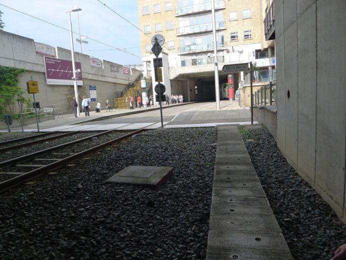
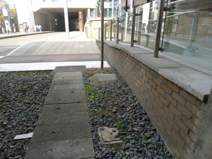
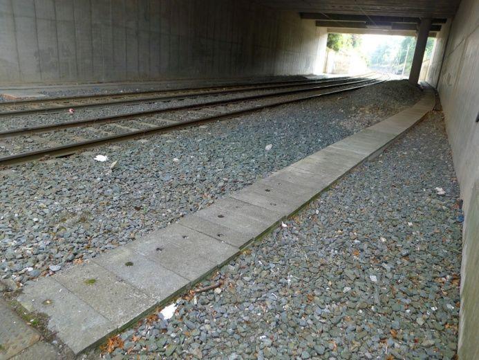
17 Milltown, Dundrum, Balally and Sandyford substations (traction transformers and switch gear) to deliver the extra power required for metro operations make up the majority of the P&S costs. For the purposes of this report, it is assumed that each scenario will require an upgrade of the power system, with Scenarios 2 and 3 demanding a more significant traction power upgrade than Scenario Signalling Upgrade The current Luas system on the Green Line operates using line of sight, where the driver is responsible for ensuring a safe distance from the vehicle in front is maintained. For the purpose of this study, each metro scenario assumes a full signalling system is installed to provide for increased safety with high service frequencies between stops. This would involve additional signalling equipment both within the track area and within the technical rooms along the line Line Segregation Works In addition to signalling, the line must be secured against trespass and passengers and other members of the public prevented or actively discouraged from encroaching on the tracks. This would require additional fencing to be installed along the alignment where such fencing is not yet in place or the replacement of existing fencing with a more secure design. For Scenarios 1 and 3, additional fencing is provided for within the cost of upgrading the stops. For Scenario 2, as it would be a fully automatic line, additional costs for barriers to ensure the line is fully segregated are included in Section Luas Stop/Platform Modifications The implementation of all three proposed metro operating scenarios will require significant upgrades and modifications to all of the existing Luas platforms. The following sections detail the type and nature of the modifications that will be required Scenario 1: 60m LFV Driver Controlled The physical characteristics of the low floor metro vehicles operating in this scenario are 60m in length and 2.65m in width. As such, while platform heights would not require modification, an extension of 7m and trimming back of the edges would be required for each platform. For the majority of stops within the study area, a high-level analysis did not reveal any major impacts for extending the platforms to 60m length, with the level of work required comparable to the current GLIU project. To allow the operation of larger vehicles (2.65m) through the existing stops, all existing platforms will have to be trimmed (including the ramps on the non-extended side), thereby setting the coping edge back by approx. 150mm as illustrated in Figure 9. This dimension would depend on type of rolling stock and dynamic kinetic envelope (DKE), along with the body shape at the door thresholds. To facilitate the platform trimming works, each stop undergoing upgrading works would require closure for service but could reopen to standard Luas operations with the adoption of a platform-totram platform filler (subject to further investigation). This filler would be in use for the time between platform works and full NMN tie-in works. The fillers would be removed once the wider metro vehicles are put in service. The scenario is more complicated where a chamber is located within the zone of Page 17 of 72

18 the tactile paving or where the platform structure is combined with a bridge deck structure (such as Ranelagh). In the latter situation, additional time would be required to re-instate reinforcement between the bridge deck and the remaining part of the platform slab. Table 1 provides a high-level summary. Figure 9: Approx. platform edge area to be removed and photo of platform edge Stop Name Construction Land Take Main Impacts RANELAGH EASY NO Equivalent to GLIU works scope BEECHWOOD EASY NO Equivalent to GLIU works scope COWPER EASY NO Equivalent to GLIU works scope MILLTOWN EASY NO Equivalent to GLIU works scope WINDY ARBOUR EASY NO Equivalent to GLIU works scope DUNDRUM EASY NO Equivalent to GLIU works scope BALALLY EASY NO Equivalent to GLIU works scope KILMACUD EASY NO Equivalent to GLIU works scope STILLORGAN EASY NO Non-segregated- Equivalent to GLIU works scope SANDYFORD EASY NO Equivalent to GLIU works scope Page 18 of 72
. As a result, the height of the platforms would increase by approx.")
19 Table 1: Line B Study Area - Scenario 1 Summary Scenario 2: 60m HFV Fully Automatic The physical characteristics of the high floor metro vehicles operating in this scenario are 60m in length, 2.65m in width and with an internal floor height of approx. 915mm from the top of rail (TOR). As a result, the height of the platforms would increase by approx. 630mm over the existing platform levels and the length of the platforms would extend by an additional 7m. As the platform end ramps would no longer be required, these would form part of the extension (while those not included within the new platform area would be demolished). In addition, the vehicles operating in this scenario are fully automated with no driver supervision and as such, maintaining safety at the platforms is paramount. To ensure passengers do not enter the track area (either accidently through falls or trips or deliberately through trespassing), Platform Safety Gates (PSGs) with an approx. height of 1,500mm would be required at each platform edge, with the vehicle doors fully aligned with the gates when stopped at the platforms and both sets of doors opening and closing in sync. A cross-section through a typical platform is illustrated in Figure 10. Figure 11 shows an over-ground platform on Copenhagen s metro system before and after the installation of PSGs. Full enclosure of the platform boundary would be achieved via barriers installed at the platform ends in addition to removal of the ramps and the existing pedestrian crossings between each side. Figure 10: Cross-section through typical upgraded stop (Scenario 2) Page 19 of 72
 at each stop.")
 This standard arrangement of footbridge and lifts was applied to each stop separately and modified to suit the local conditions.")
 for all stops within the Line B study area, the works at Ranelagh, Dundrum, Stillorgan and Sandyford would prove challenging for differing reasons outlined in the following")
20 Figure 11: High-floor Copenhagen metro - before and after installation of PSGs As passengers could no longer cross over to the opposite platform at track level, access arrangements to either platform would require significant reconfiguration, including the addition of footbridges and lifts (or modification of the same where already existing) at each stop. Figure 12 illustrates a standard platform detail with a footbridge and lift access, and fully enclosed platform edges with access gates. Figure 12: Typical arrangement at upgraded stop (Scenario 2) This standard arrangement of footbridge and lifts was applied to each stop separately and modified to suit the local conditions. It was concluded that while raising the platform level by over 600mm and providing access to each platform without passengers crossing the track area is technically feasible (while requiring significant works) for all stops within the Line B study area, the works at Ranelagh, Dundrum, Stillorgan and Sandyford would prove challenging for differing reasons outlined in the following paragraphs. At Ranelagh, as the stop is located on a bridge structure, the increase in height of the platform, surrounding balustrade and the lift structure would potentially result in a negative visual impact and additional strengthening of the bridge structure would be required. Landtake of approx. 125m 2 would be necessary to provide space for a new lift and stairs on the south-west of the bridge to access the inbound platform along with adjustments to the stair and lift heights on the outbound side (see Figure 13) Page 20 of 72
.")

21 Figure 13: Ranelagh Stop following upgrade (Scenario 2) At Dundrum Luas Stop, the existing staircase access from the Main Street side would require significant alterations to reach the raised platform height, in addition to a new lift (refer to Figure 14). On the Taney Drive side, additional steps would be required to access the raised platform, while a new lift would be required, serving the platform, the Taney Drive footpath and the underpass with a new beneath-ground landing required. Additional impacts of these works include the existing lift and the access bridge on the north side of the platform becoming redundant and a negative visual impact on the Dundrum Station House protected structure because of raising the platform height in front. Figure 14: Dundrum Stop following upgrade (Scenario 2) The Stillorgan Luas Stop would be relocated to the bridge structure crossing over the Kilmacud Upper Extension Road (refer to Section for more detail). At Sandyford, maintaining access to the lateral and island platforms would require two significant footbridge structure and three lifts (as illustrated Page 21 of 72
 A full set of drawings showing the extent of work proposed at each stop under this scenario is included in Appendix 3.")
22 in Figure 15). Additional fencing would be required along the inbound track to prevent access to the track area and this would continue either side of the track area along Blackthorn Avenue. Figure 15: Sandyford Stop following upgrade (Scenario 2) A full set of drawings showing the extent of work proposed at each stop under this scenario is included in Appendix 3. Table 2 provides a high-level summary. Stop Name Construction Land Take RANELAGH DIFFICULT YES BEECHWOOD MEDIUM NO COWPER MEDIUM NO MILLTOWN MEDIUM YES WINDY ARBOUR MEDIUM NO DUNDRUM DIFFICULT NO BALALLY EASY NO Main Impacts Visual impact on bridge with rise in platform height, bridge strengthening required. Additional access on inbound side requiring landtake. Closure of Dunville Avenue, north of stop pedestrians to use stop stair/lift and footbridge for access. Crossing south of stop closed pedestrians to use stairs/lift and footbridge for access. Both vehicular and pedestrian access to Alexandra College from Richmond Avenue South is closed pedestrians to use stop stair/lift and footbridge for access. Crossing on north of stop closed for through foot traffic pedestrians to use stop stair/lift and footbridge for access. Strengthening of existing stone retaining wall on inbound side required. Below ground works required for lift access from underpass to street and platform level. Visual impact on Dundrum Station House. Requires opening in bridge parapet for new lift access on outbound side. Existing access from retail unit maintained. Page 22 of 72

23 Stop Name Construction Land Take KILMACUD MEDIUM NO STILLORGAN DIFFICULT NO SANDYFORD DIFFICULT NO Main Impacts Existing access arrangements maintained with additional stair and lift access created on inbound side. Stop located on new overpass for grade separation of track with Upper Kilmacud Road Extension. Temporary track installation through existing Park & Ride. Outbound side stone wall requires strengthening. One set of additional stairs and lift required for access to island platform. Table 2: Line B Study Area - Scenario 2 Summary Scenario 3: 90m LFV Driver Controlled The platform lengths on the Luas Green Line, following the GLIU works, will be 53m, requiring an additional 37m to accommodate a 90m light rail vehicle as used within this scenario. Following an internal TII engineering assessment, it was concluded that while platform extensions to 90m are technically feasible for all stops within the Line B study area, the extension of Ranelagh, Cowper, Windy Arbour and Sandyford would prove challenging for differing reasons outlined in the following paragraphs. To ensure sufficient space is provided to facilitate the nearby NMN tie-in, the Ranelagh platform would require extension towards the Sandyford direction. Consequently, there would be a significant impact on the existing passenger access buildings (refer to Figure 16) located at the southern end of the platforms. The existing stairwell and platform level structure on the outbound side would be demolished while the lift shaft would be retained within a new building. The existing pedestrian underpass would also be retained and extended to provide passenger access to a new staircase and lift to the platform level. The current stairwell structure on the inbound side would be demolished and a new structure provided, set back from the structure, to provide space for the platform. This would require landtake within the green area below the stop. Figure 16: Ranelagh passenger access Page 23 of 72
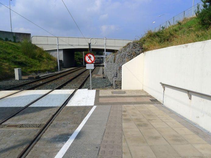
24 At Cowper Luas Stop, the preferred extension side would be northwards, requiring the taking of approx. 2.5m of nine back gardens on the inbound side. However, the gardens in question are already limited in space and removal of a 2.5m strip would remove a significant proportion of the land available to the occupants. For the purpose of this report, the platform is extended south instead, with the key drawback that the pedestrian passage across the tracks would no longer be combined with the stop pedestrian crossing. This could increase the risk of uncontrolled pedestrian crossing in the middle of the platforms and introducing approx. 80m walking detour through the platforms for prams and wheelchair users. This could also potentially add unnecessary congestion to the platforms (refer to Figure 17). Figure 17: Cowper pedestrian passage/crossing For Windy Arbour Luas Stop, the opposite approach to Cowper is proposed, in that 1.8m of seven relatively large back gardens would be taken to extend the platform southwards in order to maintain the pedestrian route across the northern end of the current stop. Extending northwards would introduce a convoluted pedestrian detour of approx. 80m, and would unnecessarily overload the platforms with pedestrian traffic and increase risk due to pedestrians directly crossing via the two platforms. Sandyford Luas Stop could only be extended northwards due to complex trackworks and geometries on the south side to allow for the links to Line B1 and the entrance to the depot. The stop is currently designed to cater for a mixed service of passing trams (Bride s Glen to St. Stephen s Green) and turning-back trams (St. Stephen s Green to Sandyford), plus the necessary connections in and out of the depot. For this reason, the stop has three tracks with three platform sides (one lateral and one island) and a series of crossovers plus a simple junction. One consequence of extending the platforms north would be the requirement to relocate one crossover and one turnout further north (refer to Figure 18). Page 24 of 72
25 Figure 18: Sandyford Stop extension Further technical information on each stop is contained within Appendix 1 and Table 3 provides a highlevel summary. In addition to the platform extension works and the associated measures required, the track facing edge of each platform would require trimming, as described in Section An upgrade to Line B (Ranelagh to Sandyford) in isolation of an upgrade to Line B1 (Sandyford to Bride s Glen) would result in the termination of metro service at Sandyford (thereby retaining a Luas service from Sandyford to Bride s Glen). In this scenario, a number of factors would require consideration as described in the following section. Stop Name Construction Land Take RANELAGH DIFFICULT YES Main Impacts Stairwell buildings on inbound and outbound side to be demolished, outbound lift retained with new stairs, with new lift and stairs on inbound side requiring landtake and new access way from Ranelagh Road. BEECHWOOD EASY NO Equivalent to GLIU works scope COWPER MEDIUM NO Crossing centre of stop closed - pedestrians to use crossing at platform for access. MILLTOWN EASY NO Equivalent to GLIU works scope Page 25 of 72
26 Stop Name Construction Land Take WINDY ARBOUR MEDIUM YES Main Impacts Landtake of 7 No. properties back gardens on the inbound southern side of the platform. DUNDRUM MEDIUM NO No major impacts BALALLY MEDIUM NO No major impacts KILMACUD MEDIUM NO No major impacts STILLORGAN EASY NO SANDYFORD MEDIUM NO Stop extension at ground level without overpass of road is straightforward. Refer to Scenario 2 for overpass. Track work required to achieve northwards extension of platforms. Table 3: Line B Study Area - Scenario 3 Summary 5.3 Sandyford Depot Implications This study provides a high-level cost assessment for the infrastructure modifications that would be required to the Sandyford Depot if it were required to accommodate the stabling of metro trams and be the termination point for metro services. In the event of a decision to terminate the metro service at Sandyford (thereby retaining a Luas service from Sandyford to Bride s Glen), a number of factors would require further consideration as follows: Interchange arrangements at Sandyford Stop: As Sandyford Stop would become a service interchange between the metro and Luas, turn-back arrangements for both metro and Luas would require further study to ensure headways can be maintained. In addition, passenger access arrangements between the two services would also need further study, especially in the event of an automated metro service due to the level of segregation involved. The operational status of Sandyford Depot: In such a scenario, the depot would either be used solely for metro stabling and maintenance (a new depot would be required to support Line B1 operations) or be retained for Luas vehicles only, requiring other arrangements for stabling of metro vehicles for start of service in the mornings and significant track work to create a new entry. Mixed occupation of the depot by both metro and Luas vehicles would result in significant technical and contractual risk and Page 26 of 72
/Line C: With a metro system operating to Sandyford, Line B1 (and a future Line B2 to Bray) would become isolated from the remainder of the Luas system.")
27 consequently is unlikely to be considered further. Expansion of the depot is not possible as the site occupies the maximum possible footprint. Line B1 isolation from Luas Cross City (LCC)/Line C: With a metro system operating to Sandyford, Line B1 (and a future Line B2 to Bray) would become isolated from the remainder of the Luas system. In order to facilitate the transfer of trams between LCC/Line C and Line B1, either an engineering link would be provided between the Charlemont terminus and the upgraded metro line, or all vehicle transfers would be carried out using the road network. In the engineering link scenario, this would also require a significant level of interoperability between the metro system running on the former Line B and the Luas vehicles. The costs estimates provided as part of this report for the Sandyford Depot modifications do not currently account for these factors Sandyford Depot Modifications - Scenario 1: 60m LFV Driver Controlled Following completion of the GLCE works, Sandyford depot will have an ultimate capacity of 30 no. 54.7m long vehicles. Following initial analysis, it has been determined that approx. 26 trams of 60m length can be stabled within the depot using this new configuration (as illustrated in Figure 19). Space proofing the 60m vehicles within the maintenance shed would require a more detailed analysis to check against the position of objects such as the pits, gantries, doors, etc. but vehicles of this length would appear to fit within the extended depot building without additional major works required. Figure 19: Sandyford Depot capacity and modifications for 60m metro vehicles Page 27 of 72

28 5.3.2 Sandyford Depot Modifications - Scenario 2: 60m HFV Fully Automatic As discussed in Section 5.3.1, initial analysis concludes that up to 26 60m long vehicles could be stabled within the depot (following the current capacity enhancement works) with minimal works required. Further detailed analysis would be required to establish the impact of automated HFVs operating within the depot environment Sandyford Depot Modifications - Scenario 3: 90m LFV Driver Controlled Figure 20 illustrates the Sandyford Depot following the GLCE works completion with 90m long vehicles superimposed in the stabling area and in the maintenance shed (outlined in blue). Following the GLCE works, the maximum stabling capacity for 53m long Luas vehicles will be 26; with a 90m metro vehicle, this figure would drop to 16. Maintenance capacity would be similarly affected; each maintenance track within the shed (as illustrated in Figure 20) could accommodate one vehicle at a time, rather than two. The sanding plant (top left in the maintenance shed) would require extending as shown hatched in Figure 20, while there would be no impact on the washing plant (top right in the shed) as this is a passthrough system. In addition, a new track extension would be required outside the lower left corner of the maintenance shed (opening a door through the building) to allow wheel-turning activities in the middle of the shed. The two stabling tracks in the loop and the single dead-end track in the delivery lane (top right in the sketch), both built as part of the GLCE project, would become redundant, as would the use of the two north apron tracks (on the left of the maintenance shed). Some of them could be re-used for maintenance vehicle parking, while the two large areas on either end of the maintenance shed built as extensions for GLCE project in 2017 would become redundant. The most critical aspect is operational; a vehicle coming off the line and waiting to be sanded would foul the rest of the entrance fan to the depot, blocking most of the other movements in and out. Figure 20: Sandyford Depot capacity and modifications for 90m metro vehicles Page 28 of 72
29 COST IMPACT ESTIMATE LINE B (RANELAGH TO SANDYFORD) This section includes the cost estimates produced for each operating scenario for upgrading Ranelagh to Sandyford to metro standard, following the engineering analysis. The costings described in this section are indicative, and additional design development and analysis would be required to provide upgrade costs with a greater level of confidence, once the final operating scenario has been chosen for NMN. 6.1 Scenario 1: 60m LFV Driver Controlled 1 All Stops 1.1 Table 4: Assumptions and Exclusions for Costing Scenario 1 Scenario 1 - Assumptions and Exclusions Rates for platform extension works, track infill panel works, stop furniture and removal and reinstatement of existing platform surfaces have been obtained from GLIU - Platform Extensions Pricing Document. 1.2 A nominal amount of 30% has been allowed for Preliminaries. It has been assumed that 1 No. Automatic Vehicle Location System (AVLS) loop will be 1.3 required at the end of the new extension. 1.4 It has been assumed that 2 No. Validators will be required at each new platform extension (4 No. per stop). 1.5 The rate for trimming of the platform edge has been generated from current market rates. 1.6 Only new balustrading required for the platform extension has been included. 2 Ranelagh Nominal amounts have been allowed for Demolition and Alterations, Property Acquisition 2.1 based on previous contracts. 2.2 The rate for the lift works has been obtained from building costs undertaken by Linesight. 4 Sandyford 4.2 The island platform rates have been generated from GLIU Contract - Harcourt platform extension. 5 Depot The estimated costs for upgrading the depot to suit each scenario will be included within the Line B1 study area costings. Page 29 of 72
30 Table 5: Cost Estimate Breakdown Scenario 1 Item Description Scenario 1 60m Low Floor Unsegregated Junction Scenario 1 60m Low Floor Segregated Junction 1 Ranelagh Stop 899, , Beechwood Stop 723, , Cowper Stop 531, , Milltown Stop 697, , Windy Arbour Stop 820, , Dundrum Stop 748, , Balally Stop 767, , Kilmacud Stop 733, , Stillorgan Stop 679, ,365, Sandyford Stop 860, , Power & Systems 8,000, ,000, Total 15,463, ,168, Design - 7.5% 1,159, ,962, Project Management % 2,242, ,794, TII Insurance and Overheads - 3% 463, , Transdev Interface 6% 927, ,570, Construction Risk and Order of 16 Magnitude 5,064, ,570, Inflation to 2.5% 3,300, ,500, Total 28,620, ,351, Difference 19,730, Page 30 of 72
31 6.2 Scenario 2: 60m HFV Fully Automatic Table 6: Assumptions and Exclusions for Costing Scenario 2 Scenario 2 - Assumptions and Exclusions 1 All Stops 1.1 The rates for Power & Systems works have been obtained from BXD_450 LCC Variation. 1.2 A nominal amount of 30% has been allowed for Preliminaries. 1.3 It has been assumed that no AVLS loops will be required. 1.4 The replacement of the stop furniture has been excluded as it is assumed that the stop furniture will be replaced to match the NMN stop furniture/branding theme. 1.5 An assumption of 600,000 has been allowed for the platform screen gates - waiting on a rate from a supplier. 1.6 Rates for platform extension works, platform-raising works, stop furniture and removal, and reinstatement of existing platform surfaces have been obtained from GLIU - Platform Extensions Pricing Document. 1.7 It has been assumed that 850,000 will be sufficient per stop for footbridges and lifts. 1.8 Platform raising works has a separate BOQ to provide clarity to the reader. 1.9 The demolition of the existing ramp at each stop - this rate was generated from GLIU Platforms Contract It has been assumed that all material used in the reinstatement of existing platform surfaces is new material and not being re-used It has been assumed that track-infill panels will not be required as the platform is now screened. 2 Beechwood 2.1 It has been assumed that the café at Beechwood Stop is property of TII and no monetary value has been included for Property Acquisition. It has been assumed that the closure of Dunville Avenue will cause issues so a monetary 2.2 value has been added to the budget for this stop. 3 Milltown 3.1 Based on rates from GLIU platform extension, a rate of 600 has been applied for the construction of approx. 19m long stone boundary wall and bulk earth removal. It has been assumed that 25,000 will suffice for the Property Acquisition form Alexandra 3.2 College (area 1.3m x 1.8m). 4 Windy Arbour A rate of 250 has been applied for re-grading the existing footpath - based on GLIU 4.1 rates. In addition, the area has been scaled off the drawings provided by TII. 7 Stillorgan 7.1 The overpass estimate was generated from Carrickmines Bridge, inflated to current prices. Page 31 of 72
32 Scenario 2 - Assumptions and Exclusions 8 Sandyford 8.1 The island platform rate has been generated from GLIU Platform extensions Harcourt. 9 Depot The estimated costs for upgrading the depot to suit each scenario will be included within the Line B1 study area costings. Table 7: Cost Estimate Breakdown Scenario 2 Item Description Scenario 2 60m High Floor Segregated Junction 1 Ranelagh Stop 3,982, Beechwood Stop 3,262, Cowper Stop 2,967, Milltown Stop 3,339, Windy Arbour Stop 3,270, Dundrum Stop 2,364, Balally Stop 2,280, Kilmacud Stop 3,085, Stillorgan Stop 12,145, Sandyford Stop 4,588, Power & Systems 31,291, Total 72,578, Design - 7.5% 5,443, Project Management % 10,523, TII Insurance and Overheads - 3% 2,177, Transdev Interface 6% 4,354, Construction Risk and Order of 16 Magnitude 23,769, Inflation to 2.5% 15,200, Total 134,046, Page 32 of 72
33 6.3 Scenario 3: 90m LFV Driver Controlled 1 All Stops 1.1 Table 8: Assumptions and Exclusions for Costing Scenario 2 Scenario 3 - Assumptions and Exclusions Rates for platform extension works, track infill panel works, stop furniture and removal, and reinstatement of existing platform surfaces have been obtained from GLIU - Platform Extensions Pricing Document. 1.2 A nominal amount of 30% has been allowed for Preliminaries. 1.3 It has been assumed that 1 No. AVLS loop will be required at the end of the new extension. 1.4 It has been assumed that 2 No. Validators will be required at each new platform extension (4 No. per stop). 1.5 The rate for trimming of the platform edge has been generated from current market rates. 1.6 Only new balustrading required for the platform extension has been included. 2 Ranelagh Nominal amounts have been allowed for Demolition and Alterations, Property Acquisition 2.1 based on previous contracts. 2.2 The rate for the lift works has been obtained from building costs undertaken by Linesight. 3 Windy Arbour Property Acquisition - it has been assumed that 30,000 per property will meet the 3.1 requirements from residents (7 No. properties). 4 Sandyford It has been assumed that no Track Infill panels are required at Sandyford as the track will be replaced due to the relocation of the specialist track equipment - crossover and turnout. The island platform rates have been generated from GLIU Contract - Harcourt platform extension. 5 Depot The estimated costs for upgrading the depot to suit each scenario will be included within the Line B1 study area costings. Page 33 of 72
34 Table 9: Cost Estimate Breakdown Scenario 3 Item Description Scenario 3 90m Low Floor Not Segregated Junction Scenario 3 90m Low Floor Segregated Junction 1 Ranelagh Stop 3,218, ,218, Beechwood Stop 1,475, ,495, Cowper Stop 1,185, ,185, Milltown Stop 1,597, ,597, Windy Arbour Stop 1,798, ,798, Dundrum Stop 1,464, ,464, Balally Stop 1,542, ,542, Kilmacud Stop 1,620, ,620, Stillorgan Stop 1,313, ,535, Sandyford Stop 1,323, ,323, Power & Systems 23,291, ,291, Total 39,831, ,073, Design - 7.5% 2,987, ,830, Project Management % 5,775, ,405, TII Insurance and Overheads - 3% 1,194, ,532, Transdev Interface 6% 2,389, ,064, Construction Risk and Order of 16 Magnitude 13,044, ,726, Inflation to 2.5% 8,400, ,700, Total 73,624, ,333, Difference 20,708, Page 34 of 72
35 6.4 Costs Summary for All Scenarios Figure 21 provides the estimated costs for converting the line section from Ranelagh and Sandyford to a metro standard to the extent required by each of the three scenarios. In the event that it is deemed that road segregation is not a requirement for Scenario 1 or 3, estimated costs for each scenario reduce by 20 million. As Scenario 2 involves a fully automated rail system, full segregation from roads and other points of interface with pedestrians and vehicles is an absolute requirement. Figure 21: Overall cost estimates for Line B for all scenarios A large proportion of the additional costs for Scenario 2 arise from the work to raise the platform heights, install safety gates at platforms and modify access routes to each platform, including foot bridges and additional lifts (as the track cannot be crossed). Page 35 of 72
36 CONCLUSION The extent of engineering work and costs for upgrading Line B (from Ranelagh to Sandyford) to a metro standard is fully contingent on the type of metro operations proposed for NMN once the two systems are connected at Ranelagh. Three different operating scenarios were chosen for this study with all three also including segregation from road junctions. Considering the vehicle passenger carrying capacities for each scenario outlined in Section 4, the following can be assumed: Scenario 1, with a 60m long, 2.65m wide low-floor light rail vehicle, operating at a headway of 2 minutes, could provide a capacity of up to 13,200 PPDPH on this corridor for approx. 50 million; Scenario 3, with the same vehicle form factor and headway as Scenario 1 but with an increased length of 90m, could provide a capacity of 22,300 PPDPH for approx. 95 million; and Scenario 2, with a high-floor fully automatic vehicle with 60m length, operating at a headway of 90 seconds, could provide a capacity of approx. 18,000 PPDPH on this line section at a cost of approx. 135 million. All figures in this study are indicative and subject to further engineering analysis. Page 36 of 72


37 APPENDICES 8.1 APPENDIX 1: LINE B STUDY AREA SCENARIO 3 STOP ANALYSIS Ranelagh Stop Ranelagh aerial view Ranelagh Stop is proposed to be extended towards Sandyford (south) to facilitate a NMN connection with steep gradient and vertical curve on the north side, which would not allow extending the platforms in that direction. Ranelagh proposed 90m extension Page 37 of 72
38 Ranelagh Stop Existing Current length Track alignment Track type Current obstructions Current access Proposal Where to extend Pedestrian access Constraints Proposed works Extended platform edge straight? Platform works Ramp works Track works (track surface) Manholes cable duct works 53m + 5.0m; lateral Straight, +0.5% grade Slab (Edilon blocks type) St. Stephen s Green side future vertical curve to link with NMN alignment. Sandyford side reduced platform width 2.2m inbound, stair and lift cores both platforms From outbound platform side only. Staircase and lift to outbound platform + pedestrian underpass to inbound platform Difficult for construction access and impacts Extend on Sandyford side by 37m plus ramp (5m) and pedestrian crossing (3m). From inbound platform side, new stairs and lift. From outbound platform side, staircase removed, lift kept. Pedestrian underpass may be kept. 2.7m wide platforms, as per existing Ranelagh platforms width. Yes Build up over existing retained embankment walkways and place of safety and cantilever additional 500mm for inbound only. Yes, new ramps on both sides (currently there is no ramp and PD at the St. Stephen s Green side). Retrofitting slab track with derailment containment in 4ft with track precast panels. Derailment containment to be dismantled in the area. Manholes, P&S Cabinet, Lighting Poles Structural works (walls, gabions, etc.) Cantilever additional 500mm for inbound platform only and reconfiguration of both vertical access cores and provision of new lift. Structural works required for both platforms to span over the original stairwell cores voids for a length of approx. 12m. Off platform drainage works Hardscape/softscape works Power and system works (Overhead Catenary System (OCS)?) Pedestrian crossing (PC) and access re-routing Other works No Hardscape: new parapets and glass panels in extended section. AVLS relocation, additional lighting, P&S Cabinet, track bonding. New PCs both sides. Access re-routing during construction based on phases. Construction access from road or private property below. Page 38 of 72
39 Impacts and land take Impact on private property? Other impacts? Pedestrian access during works No Yes, part of the grassed area south-west of the bridge will be impacted by the new access core to inbound platform. Impacted - to be agreed at construction design stage, probably variable with construction phases. Page 39 of 72

40 Ranelagh Stop photos Page 40 of 72

")


41 Beechwood Stop Beechwood aerial view Beechwood Stop is proposed to be extended towards Sandyford (south) for the presence of Dunville Avenue junction on the north side. Beechwood proposed 90m extension Page 41 of 72
42 Beechwood Stop Existing Current length Track alignment Track type Current obstructions Current access Proposal 5m + 53m + 5m; lateral Straight, +1.4% grade Ballast Beechwood Road on St. Stephen s Green side From St. Stephen s Green side, PC on both sides Easy Where to extend Extend on Sandyford side by 37m; ramp can be reduced to 4.4m to achieve 5%. Pedestrian access Constraints Proposed works Not changed Extended loading edge straight? Platform works Ramp works Track works (track surface) Manholes cable duct works Structural works (walls, gabions, etc.) Off platform drainage works Hardscape/softscape works Power and system works (OCS?) Other works Impacts Impact on private property? Other impacts? Pedestrian access during works Minor: cabinet on outbound platform No No From Dunville Avenue, unaffected. Yes Standard construction of platform slabs and ramps over existing ballast formation. Cable ducts to be incorporated into the new platforms and locally re-routed. New ramps to be built on Sandyford side. Length can be reduced to 4.4m due to gradient. Ballast track to be retrofitted with embedded pre-cast panels or fully replaced with embedded track. 2x outbound, 2x inbound No No Yes, new softscape edges on both sides. Yes, AVLS relocation, additional lighting, track bonding. No Page 42 of 72

43 Beechwood Stop photos Page 43 of 72


44 Cowper Stop Cowper Stop has the potential to be extended on both sides; therefore, both options have been examined. Cowper aerial view (St. Stephen s Green side) Cowper possible 90m extension towards St. Stephen s Green not preferred Page 44 of 72
 for property take reasons. Extending to St. Stephen s Green would require taking approx. No. 9 back gardens on the inbound side (for approx. 2.")


45 Cowper aerial view (Sandyford side) Cowper proposed 90m extension towards Sandyford preferred Following an analysis of the pros and cons, it has emerged that the preferred extension side is towards Sandyford (south) for property take reasons. Extending to St. Stephen s Green would require taking approx. No. 9 back gardens on the inbound side (for approx. 2.5m strip), while extending to Sandyford would be unlikely to require any landtake (subject to further detailed analysis), adopting a narrower than standard outbound platform (2.1m at pinch point). The negative aspect associated with extending towards Sandyford would be that the pedestrian passage across the tracks would no longer be combined with the stop pedestrian crossing thus increasing the risk of pedestrian uncontrolled crossing in the middle of the platforms. This solution would add an approx. 80m walking detour through the platforms for prams and wheelchair users, and could potentially add unnecessary congestion to the platforms. This solution would also induce a direct and uncontrolled track crossing, stepping down and up both platforms (no barriers can be placed to divert direct crossing desire line over the platforms). Page 45 of 72
46 Cowper Stop Existing Current length Staggered lateral platforms. 5m m + 5.0m Track alignment Track type Current obstructions Current access Proposal Where to extend Pedestrian access Constraints Proposed works Straight, +0.5% grade Ballast Extended loading edge straight? Platform works Ramp works Track works (track surface) Manholes cable duct works Structural works (walls, gabions, etc.) Off platform drainage works Hardscape/softscape works Power and system works (OCS?) Other works Impacts Manholes, P&S Cabinet, OCS Poles From Sandyford side only, combined with PC between the two areas split by the Luas corridor Medium difficulty for construction access Inbound: Extend on Sandyford side by 37.6m plus ramp and PC Outbound: Extend on Sandyford side by 41.8m plus ramp and PC As existing, but becoming the centre of the newly extended platforms. Crossing pedestrians and wheelchair users will have to be re-routed through the extended platforms (80m longer detour). Manholes, P&S Cabinet, OCS Poles, Luas property low wall on inbound and property boundary line on outbound side. Yes Standard construction of platform slabs and ramps over existing ballast formation. Cable ducts to be incorporated into the new platforms and locally re-routed. New ramps Sandyford side (outbound and inbound). Ballast track to be retrofitted with embedded pre-cast panels or fully replaced with embedded track. Manholes, P&S Cabinet, OCS Poles. Minor structural works to adjust walls and levels in the pedestrian access area. Low hardscape wall to be demolished on inbound side. No New landscaping and edging on both sides. Yes, AVLS relocation, additional lighting, P&S Cabinet, OCS Poles. Re-route pedestrian/cycle access. Page 46 of 72

47 Impact on private property? No if minimum 2.1m outbound platform width accepted at pinchpoint. Other impacts? Pedestrian route Pedestrian access during works As existing, only temporarily affected during part of the works. Cowper Stop photos Page 47 of 72

 towards Sandyford. Extending completely towards St. Stephen s Green would not be possible for the presence of the road junction.")
 track.")
48 Milltown Stop Milltown aerial view Milltown Stop is proposed to be extended on both sides. This is to close the gap between the current 55m extension works (towards St. Stephen s Green) and the Alexandra College access road junction (approx.17.5m), and to extend the remaining part (approx. 19.5m) towards Sandyford. Extending completely towards St. Stephen s Green would not be possible for the presence of the road junction. Extending completely towards Sandyford would not make use of the existing embedded track to the north and could potentially require landtake to the south along the south-bound (SB) track. Bringing the stop adjacent to the road junction would also be more efficient from an operational viewpoint and safer, as it combines the two pedestrian crossings in one. Milltown proposed 90m extension Page 48 of 72
49 Milltown Stop Existing Current length Track alignment Track type Current obstructions Current access Proposal Where to extend Pedestrian access Constraints Proposed works Extended platform edge straight? Platform works Ramp works Track works (track surface) Manholes cable duct works 5m + 53m + 5m; lateral Straight, +0.5% grade Structural works (walls, gabions, etc.) Off platform drainage works Hardscape/softscape works Power and system works (OCS?) Other works Ballast Sandyford, Embedded St. Stephen s Green Not major: bicycle stands and OCS tensioning poles (with protection cage) St. Stephen s Green side both inbound and outbound, stop cubicle Sandyford side inbound From both ends, with PC on both sides Easy to extend Extend on both sides, St. Stephen s Green 17.5m + 5m & Sandyford 19.5m + 5m by rebuilding ramps at the end of new platform extensions on both sides. As per existing, on both ends. Narrow platform ends Sandyford side (2.9m inbound and 2.4m outbound for the last 10m and 3m approx.), 6 manholes; bicycle racks, trees, stop cubicle. Yes Standard construction of platform slabs and ramps over existing ballast formation Sandyford side and over existing paved area St. Stephen s Green side. Cable ducts Sandyford side to be incorporated into the new platforms and locally re-routed. New ramps Sandyford side (outbound and inbound) and St. Stephen s Green side (outbound and inbound). Ballast track to be retrofitted with embedded pre-cast panels or fully replaced with embedded track Sandyford side. None St. Stephen s Green side (already embedded). 2x outbound, 2x inbound. Remove soil bank, new boundary wall (inbound-sandyford). No Bicycle racks, tree. AVLS relocation, move stop cubicle, additional lighting. No other major works Page 49 of 72

50 Impacts Impact on private property? Other impacts? Pedestrian access during works No No other major impacts As existing with staged construction, or divert via Sandyford entrance during St. Stephen s Green side works. Milltown Stop photos Page 50 of 72


51 Windy Arbour Stop Windy Arbour aerial view Windy Arbour Stop is proposed to be extended towards Sandyford in order to maintain the pedestrian route across the northern end of the current stop. Extending towards St. Stephen s Green would make the pedestrian route convoluted, adding an approx. 80m long detour, and would unnecessarily overload the platforms with pedestrian passing traffic and increase risk due to pedestrians directly crossing stepping down and up the two platforms. As there is landtake necessary on both extension sides (Sandyford and St. Stephen s Green) along the inbound track, pedestrian movements are the determining factor here. Windy Arbour proposed 90m extension Page 51 of 72
52 Windy Arbour Stop Existing Current length Track alignment Track type Current obstructions Current access Proposal Where to extend Pedestrian access Constraints Proposed works 5m + 53m; lateral Straight, +0.7% grade with vertical curve on St. Stephen s Green side Ballast Extended platform edge straight? Platform works Ramp works Track works (track surface) Manholes cable duct works Properties boundary wall on inbound-sandyford side From St. Stephen s Green side only, PC on St. Stephen s Green side only (following GLCE) Confined construction Extend on Sandyford side by 37.4m (platforms), plus 5m ramps plus 3m PC. As is, not impacted. Structural works (walls, gabions, etc.) Off platform drainage works Hardscape/softscape works Power and system works (OCS?) Other works Impacts Impact on private property? No. 7 properties (back gardens) on inbound-sandyford side, 3 manholes, P&S cabinet, OCS poles. Yes Standard construction of platform slabs and ramps over existing ballast formation and subgrade. Cable ducts to be incorporated into the new platforms and locally re-routed. GLCE inbound platform extension (narrow) to be widened for a length of 12.5m approx. Yes, on Sandyford side Ballast track to be retrofitted with embedded pre-cast panels or fully replaced with embedded track Sandyford side (45.4m). 3 manholes, P&S cabinet, poles New boundary wall (inbound-sandyford) None Yes Yes, AVLS relocation, 3 manholes, P&S cabinet, poles, additional lighting. No other major works No. 7 properties back gardens, inbound Sandyford side (58m by 1.8m strip approx.) Page 52 of 72

53 Other impacts? No other major impacts Pedestrian access during works Not impacted Windy Arbour Stop photos Page 53 of 72

54 Dundrum Stop Dundrum aerial view Dundrum Stop presents opportunities to be extended on both sides, St. Stephen s Green over the Taney Bridge, or Sandyford over the retained embankment. Current extension of GLCE is being built on the Sandyford side. The preferred solution is to proceed with a full extension towards Sandyford, as extending the platforms towards St. Stephen s Green would present more challenges as follows: Significant civil works over the bridge, more difficult from a constructability point of view and more visually intrusive (as the current deck should be raised by approx. 650mm to reach platform level); Lifting the bridge balustrade by 650mm for the length of platform extension, with significant visual impact on the architectural line of the structure; Adding significant dead load on the bridge; Difficult track retrofitting as standard pre-cast track panels would not fit over the more complex direct fixation on plinths. Track modifications to upgrade into embedded system would entail significant disruption and cost; and Modification of the levels and pedestrian ramps for both accesses at St. Stephen s Green end to inbound and outbound platforms. Page 54 of 72
 Ballast Extended loading edge straight? Taney bridge with raised plinth track and derailment containment on St.")

55 Dundrum proposed 90m extension Dundrum Stop Existing Current length Track alignment Track type Current obstructions Current access Proposal Where to extend Pedestrian access Constraints Proposed works 3.7m + 57m + 5m; lateral Straight, +0.25% grade; Horizontal curve R2700 (constant) Ballast Extended loading edge straight? Taney bridge with raised plinth track and derailment containment on St. Stephen s Green side, ESS low wall and reduced width of retained embankment inbound side on Sandyford side Lift and stairs from St. Stephen s Green end, stairs and accesses at grade from Sandyford end; PC on both sides Medium difficulty to extend Extend on Sandyford side by 33m, plus 5m ramps & 3m PC. As is, both ends untouched. Trackside cabinet, substation low wall outbound, ducting, tight property line inbound (restricting width of the inbound platform extension to min 2.1m). No, R2700 Page 55 of 72
56 Platform works Ramp works Track works (track surface) Manholes cable duct works Structural works (walls, gabions, etc.) Drainage works (other than platform) Hardscape/softscape works Power and system works (OCS?) Other works Impacts Impact on private property? Other impacts? Pedestrian access during works Not impacted No No Standard construction of platform slabs and ramps over existing ballast formation and subgrade. Cable ducts to be incorporated into the new platforms and locally re-routed. New inbound platform extension 2.1m wide towards the end, new outbound platform extension 2.4m wide at pinchpoint around ESS low wall. Yes, on Sandyford side Ballast track to be retrofitted with embedded pre-cast panels or fully replaced with embedded track Sandyford side (41m). Ducts in concrete trough set in ballast, trackside cabinet Strengthen and raise existing boundary wall (inbound-sandyford) None Yes AVLS relocation; ducts in concrete trough set in ballast, trackside cabinet, substation, additional lighting. Page 56 of 72
 Page 57 of 72")
57 Dundrum Stop photos (upper 3 photos looking Sandyford, lower photo looking St. Stephen s Green) Page 57 of 72


58 Balally Stop Balally aerial view Balally Stop is proposed to be extended towards Sandyford as there is insufficient width within the underpass towards St. Stephen s Green (refer to photos on the right, looking towards St. Stephen s Green). This extension will almost entirely fall within the existing underpass box beneath the office building. Balally proposed 90m extension Page 58 of 72
59 Balally Stop Existing Current length Track alignment Track type Current obstructions Current access Proposal Where to extend Pedestrian access Constraints Proposed works 53m + 5m; lateral Straight, +1.3% to 1.5% grade; Horizontal curve R510 Ballast Extended platform edge straight? Platform works Ramp works Track works (track surface) Manholes cable duct works Structural works (walls, gabions, etc.) Off Platform Drainage works Hardscape/softscape works Power and system works (OCS?) Impacts Impact on private property? Other impacts? Pedestrian access during works Building by others over the trackwork restricting width on St. Stephen s Green side, columns on the Sandyford side Lift, stairs to the centre of inbound platform, stairs only to the centre and Sandyford side of outbound platform; PC on Sandyford side only Medium difficulty to extend - accessibility Extend on Sandyford side by 37m, plus 5m ramps & 3m PC. As is, both sides untouched. Ducts in concrete trough, structural columns inbound side. No No No, horizontal curve with R510 Standard construction of platform slabs and ramps over existing ballast formation and subgrade. Cable ducts to be incorporated into the new platforms and locally re-routed. Yes, on Sandyford side. Not possible to provide ramps and PC on St. Stephen s Green side. Ballast track to be retrofitted with embedded pre-cast panels or fully replaced with embedded track Sandyford side (41m). Ducts in concrete trough set in ballast. None None Yes AVLS relocation, additional lighting under the tunnel. Page 59 of 72

60 Impacted. Construction in stages due to wheelchair users not having access to outbound platform from above. Balally Stop Photos Page 60 of 72


61 Kilmacud Stop Kilmacud aerial view Kilmacud Stop has the potential to be extended on both sides but it is proposed to fully extend it towards Sandyford as this side shows less constraints. This is also in consideration of the fact that there is sufficient width under the Sandyford side pedestrian overbridge. Kilmacud proposed 90m extension Page 61 of 72
62 Kilmacud Stop Existing Current length Track alignment Track type Current obstructions Current access Proposal Where to extend Pedestrian access Constraints Proposed works 5m + 53m + 5m; lateral Horizontal curve R 1,150m (very large) Ballast Limited obstructions on both sides: low retaining wall on Sandyford side outbound, gabions and cabinets/manholes on SSG side. Separate lifts and stairs to the centre of both platform; PC on both sides Medium difficulty to extend for accessibility Extend on Sandyford side by 37m, plus 5m ramps & 3m PC. As is, both sides untouched. Ducts in concrete trough both sides, 1.8m high retaining wall outbound, overbridge abutments (at an offset of 3.6m and 4.0m from nearest rail, leaving a platform width of in excess of 3.0m), OCS tensioning poles (one on each side) Extended platform edge straight? No, R 1,150m Platform works Ramp works Track works (track surface) Manholes cable duct works Structural works (walls, gabions, etc.) Off platform drainage works Hardscape/softscape works Power and system works (OCS?) Other works Impacts Impact on private property? Other impacts? No No Standard construction of platform slabs and ramps over existing ballast formation and subgrade. Cable ducts to be incorporated into the new platforms and locally re-routed. Yes, on Sandyford side. Ballast track to be retrofitted with embedded pre-cast panels or fully replaced with embedded track Sandyford side (37m). Ducts in concrete trough set in ballast and 1 manhole per side Low wall to be demolished and re-built set-back. None Both on both sides following extension works, some rock head trimming back on inbound platform side and protection net to be re-fixed. AVLS relocation, additional lighting columns. Page 62 of 72


63 Pedestrian access during works Not impacted. Kilmacud Stop photos Page 63 of 72

")

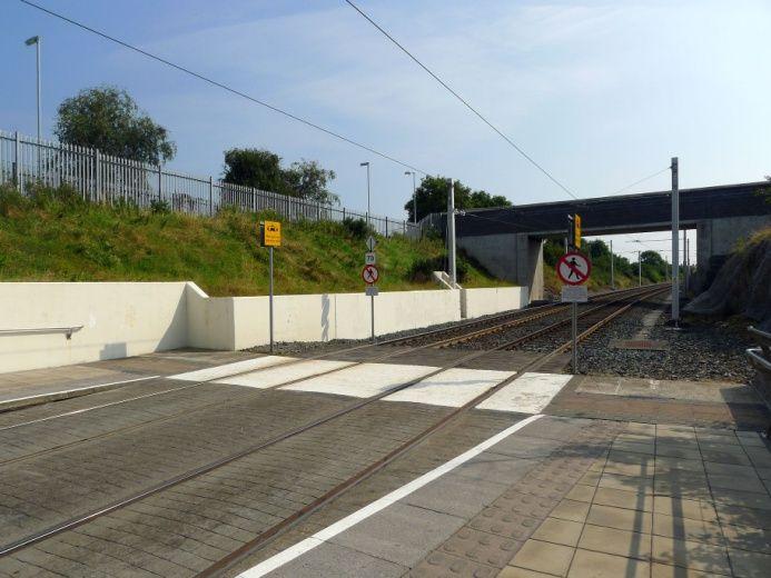
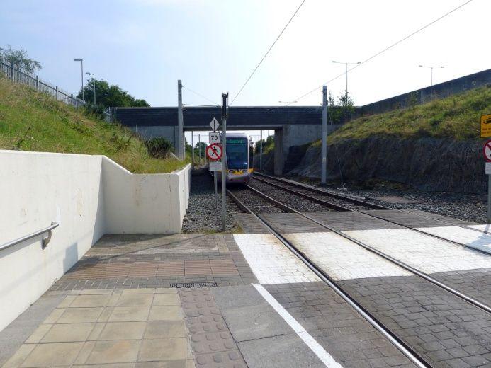
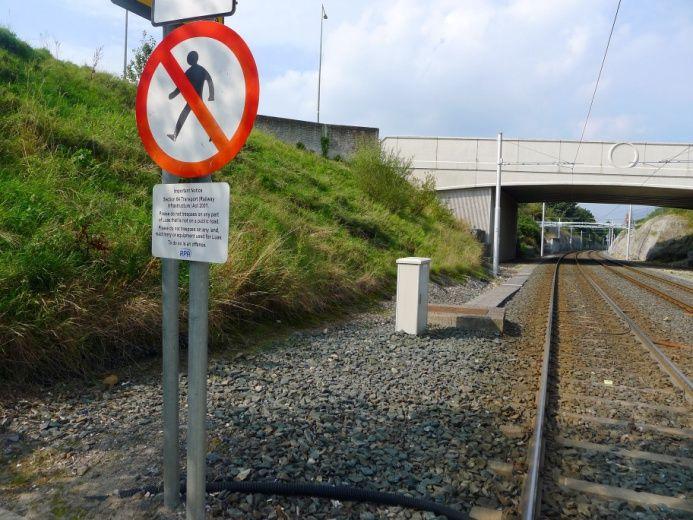
64 Stillorgan Stop (non-segregated) Stillorgan aerial view Stillorgan Stop has the potential to be extended on both sides and it is proposed to do so to make the best use of public space and of the remaining section of embedded track between the current stop and the road junction. This is also in consideration of the fact that combining the two PCs (road junction and stop) is safer and operationally more efficient. Works on the two sides will be carried out in two phases not to block both stop accesses and ramps. Stillorgan proposed 90m extension Page 64 of 72
65 Stillorgan Stop Existing Current length Track alignment Track type Current constraints Current access Proposal Where to extend Pedestrian access Proposed works 5m + 53m + 5m Straight St. Stephen s Green Embedded Sandyford Ballast None Free access to both platforms - PC on both sides Easy St. Stephen s Green side 13m + 5m ramp, Sandyford side 24m + 5m ramp + 3m PC As per existing Extended platform edge straight? Platform works Ramp works Track works (track surface) Manholes cable duct works Structural works (walls, gabions, etc.) Drainage works (other than platform) Hardscape/softscape works Power and system works (OCS?) Other works Pedestrian access during works Yes Standard construction of platform slabs and ramps over existing ballast formation and subgrade on Sandyford side. Cable ducts to be incorporated into the new platforms and locally re-routed. Standard construction of platform slabs and ramps over existing paved areas. Demolish and rebuild no. 2 5m long ramps with 3m wide pedestrian crossings Sandyford side only, 24m of track retrofitting panels over ballast track or new embedded track. No. 4 manholes on St. Stephen s Green side to be lifted and incorporated into the platform and ballast cable duct plus no. 3 manholes on Sandyford side. No No Yes, hardscape on St. Stephen s Green side and Softscape on Sandyford side. AVLS relocation. Stop cubicle on inbound Sandyford side can be kept and platform built around its basement (local pinchpoint). No Page 65 of 72


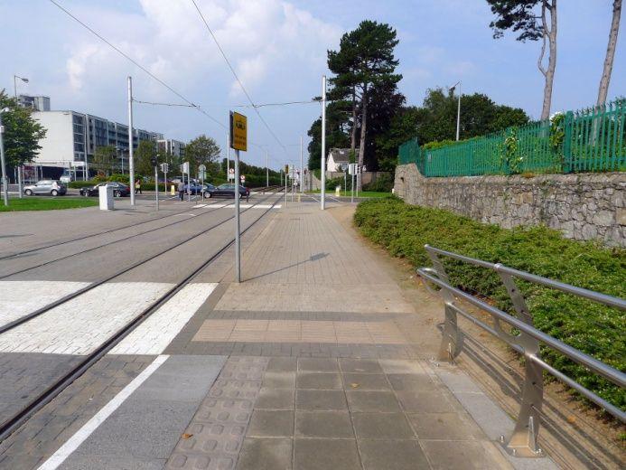
66 One side at a time, works phased. Stillorgan Stop photos Page 66 of 72

, plus the necessary connections in and out of the adjacent depot.")
67 Sandyford Stop Sandyford aerial view Sandyford Stop can only be extended towards St. Stephen s Green as there are complex trackworks and geometries on the Sandyford side to allow for the links to Line B1 and the entrance to the depot. The stop is currently designed to cater for a mixed service of passing trams (Bride s Glen-St. Stephen s Green) and turning-back trams (St. Stephen s Green-Sandyford), plus the necessary connections in and out of the adjacent depot. For this reason, the stop has three tracks with three side platforms (one lateral and one island) and a series of crossovers plus a simple junction. This functional configuration is deemed necessary and sufficient for the future NMN line upgrade, even with the increased frequencies. The design proposal is therefore to maintain the current functional lay-out, while extending the two platforms to 90m, and shifting all the necessary trackworks towards St. Stephen s Green (one crossover and the third track connection one turnout). Page 67 of 72

68 Sandyford proposed 90m extension Sandyford Stop Existing Current length Track alignment Current constraints Current access Proposal Where to extend Pedestrian access Proposed works 5m + 53m + 5m Straight Extended loading edge straight? Platform works Ramp works Track works (track surface) Trackworks on both sides, with Sandyford side trackworks not modifiable (Line B1 link and entrance to depot) Free access to both platforms - PC on both sides Easy St. Stephen s Green side 37m + 5m ramp + 3m PC As per existing Yes (R4,000 not visible) Standard construction of platform slabs and ramps over existing ballast formation and subgrade on St. Stephen s Green side. Cable ducts to be incorporated into the new platforms and locally rerouted. Demolish and rebuild 5m long ramps with 3m wide pedestrian crossings. 37m of new embedded track. Page 68 of 72
 Other works Pedestrian access during works As existing, in phases. Ducts in concrete trough set in ballast and 1 manhole per side. No No Yes, hardscape on St.")
69 Manholes cable duct works Structural works (walls, gabions, etc.) Drainage works (other than platform) Hardscape/softscape works Power and system works (OCS?) Other works Pedestrian access during works As existing, in phases. Ducts in concrete trough set in ballast and 1 manhole per side. No No Yes, hardscape on St. Stephen s Green side and softscape on Sandyford side. AVLS relocation. Stop cubicle on inbound Sandyford side can be kept and platform built around its basement (local pinchpoint). Trackworks. Extending third track by 37m and shifting existing ballast turnout. Shifting existing ballast crossover. All systems to be shifted and updated accordingly. Modify vertical track alignment to shift vertical curve away from new crossover location, this is likely to have an impact over up to 300m long ballast track section to be lifted and slewed (no new track, just existing ballast track alignment modification). Page 69 of 72

70 Sandyford Stop photos Page 70 of 72
71 8.2 APPENDIX 2: LINE B STUDY AREA SCENARIO 2 PLATFORM DRAWINGS Page 71 of 72
72 8.3 APPENDIX 3: LINE B STUDY AREA SCENARIO 3 PLATFORM DRAWINGS Page 72 of 72


73
SUBMISSION TO METROLINK PUBLIC CONSULTATION. From: Eamon Ryan TD Dáil Éireann, Kildare Street, Dublin 2 Date: 8th May 2018
 SUBMISSION TO METROLINK PUBLIC CONSULTATION From: Eamon Ryan TD Dáil Éireann, Kildare Street, Dublin 2 Date: 8th May 2018 Suggested Route Map including stations Rathmines, Terenure, Rathfarnham INTRODUCTION
Submission to Minister for Transport With respect to the public inquiry concerning Luas Line B1. Platform 11 Dublin Rail Projects Committee 1
 Submission to Minister for Transport With respect to the public inquiry concerning Luas Line B1 Platform 11 Dublin Rail Projects Committee 1 January 17, 2006 1 The chair of the committee may be contacted
Location Concept Plan Amendment Recommendation Approved 2011 Concept Plan
 Valley Line West LRT Concept Plan Recommended Amendments Lewis Farms LRT Terminus Site Location Concept Plan Amendment Recommendation Approved 2011 Concept Plan Lewis Farms LRT terminus site, 87 Avenue/West
TORONTO TRANSIT COMMISSION REPORT NO.
 Form Revised: February 2005 TORONTO TRANSIT COMMISSION REPORT NO. MEETING DATE: October 24, 2012 SUBJECT: DOWNTOWN RAPID TRANSIT EXPANSION STUDY (DRTES) PHASE 1 STRATEGIC PLAN ACTION ITEM RECOMMENDATIONS
Sandyford - Brides Glen (Line B1)
") LUAS GREEN LINE WILL SERVE CHERRYWOOD FROM 11AM ON SATURDAY 16 OCTOBER 2010 RPA are proud to inform you that the new Cherrywood Luas Line will open on Saturday 16 October 2010 at 11 am. This new 7.5km
LUAS GREEN LINE WILL SERVE CHERRYWOOD FROM 11AM ON SATURDAY 16 OCTOBER 2010 RPA are proud to inform you that the new Cherrywood Luas Line will open on Saturday 16 October 2010 at 11 am. This new 7.5km
Submission to Greater Cambridge City Deal
 What Transport for Cambridge? 2 1 Submission to Greater Cambridge City Deal By Professor Marcial Echenique OBE ScD RIBA RTPI and Jonathan Barker Introduction Cambridge Futures was founded in 1997 as a
Table Station Elements
 The overall layout of the station in the Preferred Alternative (Modified Alternative 2) is described in Table 7.5-1. Table 7.5-1 Station Elements Ground Level Mezzanine Level Platform Level Existing/Upgraded
1 Downtown LRT Connector: Draft Concept
 Downtown LRT Connector: Draft Concept Plan November 2010 We re moving forward. Get involved. On June 21, 2010, City Council approved a street-level downtown LRT route, including a connector for the future
West LRT. Alignment Update and Costing Report May Calgary Transit Transportation Planning Clifton ND Lea Consultants
 West LRT Alignment Update and Costing Report 2006 May Calgary Transit Transportation Planning Clifton ND Lea Consultants West LRT Update Background The service area for West LRT is generally described
Iarnród Éireann Dublin Integrated Rail Plan Presentation to Institution of Engineers of Ireland. 17 th November
 Iarnród Éireann Dublin Integrated Rail Plan Presentation to Institution of Engineers of Ireland 17 th November 2004 www.irishrail.ie Contents Overview of current suburban rail network Projects underway
Green Line LRT: Beltline Segment Update April 19, 2017
 Green Line LRT: Beltline Segment Update April 19, 2017 Quick Facts On April 11, 2017, City Council approved Administration s recommendation for the Green Line to be underground in the Beltline from 2 Street
Bi-County Transitway/ Bethesda Station Access Demand Analysis
 Bi-County Transitway/ Bethesda Station Access Demand Analysis Prepared for: Washington Metropolitan Area Transit Authority Office of Planning and Project Development May 2005 Prepared by: in conjunction
IMPROVEMENT CONCEPTS
 IMPROVEMENT CONCEPTS for the South Novato Transit Hub Study Prepared by: January 11, 2010 DKS Associates With Wilbur Smith Associates IMPROVEMENT CONCEPTS Chapter 1: Introduction 1. INTRODUCTION The strategic
Terminal Alternatives
 Chapter 5 Terminal Alternatives Missoula International Airport Master Plan Update Prepared for Missoula County Airport Authority OCTOBER 2008 Contents Section Page 5 Terminal Alternatives...5-1 5.1 Terminal
Converting BRT to LRT in the Nation s Capital Ottawa, Canada. John Manconi City of Ottawa Ottawa, Canada
 Converting BRT to LRT in the Nation s Capital Ottawa, Canada John Manconi City of Ottawa Ottawa, Canada 1 The Challenge *Mackenzie King Bridge Ottawa, AM peak period 2 The Challenge Ottawa s population
Spadina Subway Extension Downsview Station to Steeles Avenue Environmental Assessment
 Spadina Subway Extension Downsview Station to Steeles Avenue Environmental Assessment APPENDIX Q SUBWAY OPERATIONS REPORT Spadina Subway Extension Downsview Station to Steeles Avenue Environmental Assessment
RSC-G-004-B Guidelines For The Design Of Section 3 3 ELECTRIC TRACTION SYSTEMS 2
 3 ELECTRIC TRACTION SYSTEMS 2 3.1. SAFE FOR PEOPLE 2 3.1.1. Electric Traction System 2 3.1.2. Protection against unwanted access 2 3.1.3. Fencing 2 3.1.4. On bridges and other structures 2 3.1.5. At level
4.2 Series Station Option Description
 4.2 Series Station Option Description The series station proposal features a new set of side platforms constructed approximately 250 feet north of the existing platforms. The two new platforms would extend
CITY OF LONDON STRATEGIC MULTI-YEAR BUDGET ADDITIONAL INVESTMENTS BUSINESS CASE # 6
 2016 2019 CITY OF LONDON STRATEGIC MULTI-YEAR BUDGET ADDITIONAL INVESTMENTS BUSINESS CASE # 6 STRATEGIC AREA OF FOCUS: SUB-PRIORITY: STRATEGY: INITIATIVE: INITIATIVE LEAD(S): BUILDING A SUSTAINABLE CITY
Powering Sydney s Future
 Powering Sydney s Future Frequently Asked Questions December 2017 Project background Q: Why is this project needed? A: Inner Sydney is one of the most critical parts of the NSW electricity network. However,
Chapter 4 : THEME 2. Transportation
 Chapter 4 : THEME 2 Strengthen connections to keep the Central Area easy to reach and get around 55 Figure 4.2.1 Promote region-wide transit investments. Metra commuter rail provides service to the east,
Chapter 5 Route Window NE4 Ilford station. Transport for London
 Chapter 5 Route Window NE4 Ilford station ILFORD STATION 5 Route Window NE4 Ilford station 5.6 The construction programme for the station works is expected to take about two years. Operations at Aldersbrook
Green Line LRT: Beltline Recommendation Frequently Asked Questions
 Green Line LRT: Beltline Recommendation Frequently Asked Questions June 2017 Quick Facts Administration has evaluated several alignment options that would connect the Green Line in the Beltline to Victoria
THE DUBLIN TRANSPORTATION INITIATIVE: HOW INTEGRATED TRANSPORTATION SOLUTIONS CHANGE A CITY
 THE DUBLIN TRANSPORTATION INITIATIVE: HOW INTEGRATED TRANSPORTATION SOLUTIONS CHANGE A CITY Innovations in Regional Transportation Plans Rail~Volution Conference, Miami 2007 Alan Jones Associate November
Light rail, Is New Zealand Ready for Light Rail? What is Needed in Terms of Patronage, Density and Urban Form.
 Light rail, Is New Zealand Ready for Light Rail? What is Needed in Terms of Patronage, Density and Urban Form. THE PROBLEM LIGHT RAIL THE SOLUTION? INTRODUCTION Light rail transit (LRT) provides the opportunity
Note: The October 2007 version of this report has been updated in this December 2008 report to present costs in year 2007 dollars.
 Sound Transit Phase 2 South Corridor LRT Design Report: SR 99 and I-5 Alignment Scenarios (S 200 th Street to Tacoma Dome Station) Tacoma Link Extension to West Tacoma Prepared for: Sound Transit Prepared
STRATEGIC PRIORITIES AND POLICY COMMITTEE MAY 5, 2016
 STRATEGIC PRIORITIES AND POLICY COMMITTEE MAY 5, 2016 Shift Rapid Transit Initiative Largest infrastructure project in the city s history. Rapid Transit initiative will transform London s public transit
Town of Londonderry, New Hampshire NH Route 28 Western Segment Traffic Impact Fee Methodology
 Town of Londonderry, New Hampshire NH Route 28 Western Segment Traffic Impact Fee Methodology Prepared by the Londonderry Community Development Department Planning & Economic Development Division Based
4 COSTS AND OPERATIONS
 4 COSTS AND OPERATIONS 4.1 INTRODUCTION This chapter summarizes the estimated capital and operations and maintenance (O&M) costs for the Modal and High-Speed Train (HST) Alternatives evaluated in this
4. Transportation Plan
 The sizes of the most suitable sites are indicated in Table 4.3.6.2. Table 4.3.6.2: Site Sizes and Potential Development Area Potential Development Site Site Size (m 2 ) Area m 2 (3 Floors) D1 29,000 87,000
THE WAY WE MOVE LRT FOR EVERYONE
 THE WAY WE MOVE LRT FOR EVERYONE 2 LRT for Everyone LRT FOR EVERYONE Light rail is about more than transit; it s about transforming Edmonton. As the city grows, so do its transportation needs. LRT is an
4.0 TIER 2 ALTERNATIVES
 4.0 TIER 2 ALTERNATIVES The Tier 2 Alternatives represent the highest performing Tier 1 Alternatives. The purpose of the Tier 2 Screening was to identify the LPA utilizing a more robust list of evaluation
WATFORD LOCAL PLAN PART 2. Review of Car Parking Policy and Standards. Evidence Base. February 2012
 WATFORD LOCAL PLAN PART 2 Review of Car Parking Policy and Standards Evidence Base February 2012 1.0 Background 1.1 The Watford District Plan 2000 contains various policies relating to the provision of
Chapter 11 Route Window NE10 Gidea Park station. Transport for London
 Chapter 11 Route Window NE10 Gidea Park station Transport GIDEA PARK STATION 11 Route Window NE10 Gidea Park station Transport Introduction 11.1 The construction activities in this route window are associated
The Engineering Department recommends Council receive this report for information.
 CORPORATE REPORT NO: R161 COUNCIL DATE: July 23, 2018 REGULAR COUNCIL TO: Mayor & Council DATE: July 19, 2018 FROM: General Manager, Engineering FILE: 8740-01 SUBJECT: Surrey Long-Range Rapid Transit Vision
SEPULVEDA PASS CORRIDOR
 SEPULVEDA PASS CORRIDOR PUBLIC PRIVATE PARTNERSHIP DELIVERY PRE-DEVELOPMENT AGREEMENT PDA Sepulveda Pass Mobility Issues Most congested highway segment in the U.S. 295,000 vehicles per day (2010) 430,000
INTRODUCTION. Ansaldo STS. Ansaldo STS is a leading technology company operating in railway and underground transportation.
 Brescia Subway INTRODUCTION The origin of the project Metro Brescia comes from a decision of Brescia city council in 1987, when in accordance with the technical and economic examination of the various
Pace Bus Depot Location Analysis
 Pace Bus Depot Location Analysis Key Notes 1. Options refer to conceptual sketches prepared by Kimley Horn. 2. The depot is assumed to accommodate Pace routes as they currently exist: 17 routes on the
BUS SERVICES IN CHAMBERLAYNE ROAD NW10
 INTRODUCTION BUS SERVICES IN CHAMBERLAYNE ROAD NW10 1 LONDON BUSES 1. This note reviews the issues in Chamberlayne Road, Kensal Rise. It covers the range of bus routes in the area, their characteristics
On June 11, 2012, the Park Board approved the installation of three electric vehicle charging stations along Beach Avenue.
 January 8, 2017 TO: Park Board Chair and Commissioners FROM: General Manager Vancouver Board of Parks and Recreation SUBJECT: Electric Vehicle Charging Stations New Park Board Locations RECOMMENDATION
Attachment 5 Eglinton West LRT Planning and Technical Update
 Eglinton West LRT Planning and Technical Update 1. Introduction In July 2016, City Council approved an Eglinton West LRT with between 8 and 12 stops between Mount Dennis and Renforth Gateway, and up to
RE: A Traffic Impact Statement for a proposed development on Quinpool Road
 James J. Copeland, P.Eng. GRIFFIN transportation group inc. 30 Bonny View Drive Fall River, NS B2T 1R2 May 31, 2018 Ellen O Hara, P.Eng. Project Engineer DesignPoint Engineering & Surveying Ltd. 200 Waterfront
NEW HAVEN HARTFORD SPRINGFIELD RAIL PROGRAM
 NEW HAVEN HARTFORD SPRINGFIELD RAIL PROGRAM Hartford Rail Alternatives Analysis www.nhhsrail.com What Is This Study About? The Connecticut Department of Transportation (CTDOT) conducted an Alternatives
Three ULTra Case Studies examples of the performance of the system in three different environments
 Three ULTra Case Studies examples of the performance of the system in three different environments airport application: London Heathrow : linking business and staff car parks through the access tunnel
Madison BRT Transit Corridor Study Proposed BRT Operations Plans
 Madison BRT Transit Corridor Study Proposed BRT Operations Plans This paper presents a description of the proposed BRT operations plan for use in the Madison BRT Transit Corridor Study. The objective is
CITY OF ANN ARBOR, MICHIGAN 301 E. Huron St., P.O. Box 8647 Ann Arbor, Michigan
 Date: Wednesday, June 24, 2014 Location: Ann Arbor District Library Attendees: 40 citizen attendees Ann Arbor Station Environmental Review Public Meeting Meeting Notes Meeting #2 The second public meeting
TORONTO TRANSIT COMMISSION REPORT NO.
 Form Revised: February 2005 TORONTO TRANSIT COMMISSION REPORT NO. MEETING DATE: May 28, 2009 SUBJECT: DON MILLS STATION ACTION ITEM RECOMMENDATIONS It is recommended that the Commission: 1. Endorse the
Railyard Alternatives & I-280 Boulevard Feasibility Study 1 RAILYARD ALTERNATIVES & I-280 BOULEVARD (RAB) FEASIBILITY STUDY
 FEASIBILITY STUDY") Railyard Alternatives & I-280 Boulevard Feasibility Study 1 RAILYARD ALTERNATIVES & I-280 BOULEVARD (RAB) FEASIBILITY STUDY RAB Citizen Working Group Meeting, August 1 st 2016 CITIZEN WORKING GROUP (CWG)
Railyard Alternatives & I-280 Boulevard Feasibility Study 1 RAILYARD ALTERNATIVES & I-280 BOULEVARD (RAB) FEASIBILITY STUDY RAB Citizen Working Group Meeting, August 1 st 2016 CITIZEN WORKING GROUP (CWG)
FINAL. Sound Transit Long-Range Plan Update. Issue Paper S.1: Tacoma Link Integration with Central Link. Prepared for: Sound Transit
 Sound Transit Long-Range Plan Update Issue Paper S.1: Tacoma Link Integration with Central Link Prepared for: Sound Transit Prepared by: Quade & Douglas, Inc. FINAL March 2005 Foreword This issue paper
Report Date: May 18, 2012 Contact: Al Zacharias Contact No.: RTS No.: 9587 VanRIMS No.: Meeting Date: June 12, 2012
 A5 ADMINISTRATIVE REPORT Report Date: May 18, 2012 Contact: Al Zacharias Contact No.: 604.873.7214 RTS No.: 9587 VanRIMS No.: 08-2000-21 Meeting Date: June 12, 2012 TO: FROM: SUBJECT: Vancouver City Council
Challenges in a Post-Katrina Environment East-West Corridor Project Overview February, 2007
 EAST-WEST CORRIDOR Challenges in a Post-Katrina Environment East-West Corridor Project Overview February, 2007 Presentation Agenda Project Overview / Purpose and Need Highway Component Transit Component
Modernising the Great Western railway
 Report by the Comptroller and Auditor General Department for Transport and Network Rail Modernising the Great Western railway HC 781 SESSION 2016-17 9 NOVEMBER 2016 4 Key facts Modernising the Great Western
BIRMINGHAM CONNECTED Anne Shaw Tuesday 20 January 2015
 BIRMINGHAM CONNECTED Anne Shaw Tuesday 20 January 2015 www.birmingham.gov.uk/connected Birmingham Connected Setting the context challenges in Birmingham The need for action The EU the SUMP process Strategy
Executive Summary. Draft Environmental Impact Statement/Environmental Impact Report ES-1
 Executive Summary Introduction The Eastside Transit Corridor Phase 2 Project is a vital public transit infrastructure investment that would provide a transit connection to the existing Metro Gold Line
Downtown Lee s Summit Parking Study
 Downtown Lee s Summit Parking Study As part of the Downtown Lee s Summit Master Plan, a downtown parking and traffic study was completed by TranSystems Corporation in November 2003. The parking analysis
The following section summarises the present conditions related to transportation for the proposed development of the Matimba B Power Station:
 14. TRAFFIC AND TRANSPORT 14.1. Status Quo Conditions The following section summarises the present conditions related to transportation for the proposed development of the Matimba B Power Station: 14.1.1.
The City of Toronto s Transportation Strategy July 2007
 The City of Toronto s Transportation Strategy July 2007 Presentation Outline Transportation Statistics Transportation Building Blocks Toronto s Official Plan Transportation and City Building Vision Projects
San Rafael Transit Center. Update. Golden Gate Bridge, Highway & Transportation District Transportation Committee of the Board of Directors
 Transportation Committee November 17, 2016 Agenda Item No. 5, Update on the San Rafael Transit Center Relocation San Rafael Transit Center Relocation Study Update 11/17/16 Golden Gate Bridge, Highway &
Enterprise Services, General Manager Technical Standards. Track and Civil Code of Practice Section 7 Clearances Technical Note ETD-07-01
 TO FROM Network Wide Enterprise Services, General Manager Technical Standards DATE 09/11/2017 SUBJECT Track and Civil Code of Practice Section 7 Clearances Technical Note ETD-07-01 TITLE Technical Note
ANDERSON PROPERTY SITE ANALYSIS
 ANDERSON PROPERTY SITE ANALYSIS Introduction The Montgomery County Department of Transportation (MCDOT) initiated a feasibility study in the fall of 2012 to evaluate the need for transit service expansion
US 81 Bypass of Chickasha Environmental Assessment Public Meeting
 US 81 Bypass of Chickasha Environmental Assessment Public Meeting March 14, 2013 Introductions ODOT FHWA SAIC Meeting Purpose Present need for bypass Provide responses to 10/04/11 public meeting comments
Preliminary Definition of Alternatives. 3.0 Preliminary Definition of Alternatives
 3.0 What preliminary alternatives are being evaluated? The alternatives for the East San Fernando Valley Transit Corridor project that were considered for screening include the No Build Alternative, Transportation
PROJECTS $500K AND OVER FOR 2012
 EB-0-0 Page of PROJECTS $00K AND OVER FOR 0 EXTERNALLY INITIATED PLANT RELOCATIONS PORTFOLIO Table : Externally Initiated Plant Relocations Projects Estimate Estimated Cost Project Title Number ($ Millions)
Luas an accessible Light Rail system. Jim Quinlan, Chief Architect, Railway Procurement Agency
 Luas an accessible Light Rail system Jim Quinlan, Chief Architect, Railway Procurement Agency Who are we? Railway Procurement Agency enabling agency Established 28/12/01 Semi-State Board of Directors and
TRAFFIC ENGINEERING ASSESSMENT MOUNT EDEN ROAD, MOUNT EDEN
 12 September 2017 Iain McManus Civitas Planning Consultants PO Box 47020 Ponsonby AUCKLAND 1144 Dear Iain, TRAFFIC ENGINEERING ASSESSMENT 43-45 45 MOUNT EDEN ROAD, MOUNT EDEN As requested, we have prepared
Forest Hill Street Clutter study
 1 Local Fund and Street Clutter London Borough of Lewisham Forest Hill Street Clutter study Colin Davis Associates Traffic and Urban Design consultants January 2010 020 8398 7837 colinjdavis@aol.com www.publicrealm.info
STH 60 Northern Reliever Route Feasibility Study Report
 #233087 v3 STH 60 Northern Reliever Route Feasibility Study Report Washington County Public Works Committee Meeting September 28, 2016 1 STH 60 Northern Reliever Route Feasibility Study Hartford Area Development
Welcome The City has undertaken a naming exercise for the existing and future LRT lines. The SE to West LRT, as the project has been called to date,
 Welcome The City has undertaken a naming exercise for the existing and future LRT lines. The SE to West LRT, as the project has been called to date, is now called the Valley Line. We are here to present
City of Palo Alto (ID # 6416) City Council Staff Report
 City Council Staff Report") City of Palo Alto (ID # 6416) City Council Staff Report Report Type: Informational Report Meeting Date: 1/25/2016 Summary Title: Update on Second Transmission Line Title: Update on Progress Towards Building
City of Palo Alto (ID # 6416) City Council Staff Report Report Type: Informational Report Meeting Date: 1/25/2016 Summary Title: Update on Second Transmission Line Title: Update on Progress Towards Building
Executive Summary. Phase 2 Evaluation Report. Introduction
 , Executive Summary Executive Summary Introduction TransLink and the Province of British Columbia sponsored a multi-phase study to evaluate alternatives for rapid transit service in the Broadway corridor
Proposed Dounreay - Mybster 275 kv / 132 kv
 Background Scottish Hydro-Electric Transmission Ltd (SHETL) is proposing a new 275 kilovolt (kv) (1 kilovolt = 1000volts) double circuit overhead line (OHL) between the Dounreay sub station and the new
committee report General Permitted Development Order SPT response to consultation
 committee report General Permitted Development Order SPT response to consultation Committee Strategy and Programmes Date of meeting 24 June 2011 Date of report 1 June 2011 Report by Assistant Chief Executive
Pedestrians, Cars, Buses and Trains? Considerations for Rapid Transit Service at Western University
 Pedestrians, Cars, Buses and Trains? Considerations for Rapid Transit Service at Western University Shift: The City of London s Rapid Transit Proposal Shift: The City of London s Rapid Transit Proposal
Travel Forecasting Methodology
 Travel Forecasting Methodology Introduction This technical memorandum documents the travel demand forecasting methodology used for the SH7 BRT Study. This memorandum includes discussion of the following:
I-290 Phase I Study Summary of NFPA-130 Analysis of Proposed CTA Station Platform Widths May 2016
 I-290 Phase I Study Summary of NFPA-130 Analysis of Proposed CTA Station Platform Widths May 2016 INTRODUCTION As part of the I-290 reconstruction phase I study, IDOT has coordinated with the CTA regarding
Update on Community or Heritage Rail Project (Project Manager Services) The Engineering Department recommends that Council:
 The Engineering Department recommends that Council:") Corporate NO: R279 Report COUNCIL DATE: DECEMBER 18, 2006 REGULAR COUNCIL TO: Mayor & Council DATE: December 15, 2006 FROM: General Manager, Engineering FILE: 8710-20 (Heritage) SUBJECT: Update on Community
Corporate NO: R279 Report COUNCIL DATE: DECEMBER 18, 2006 REGULAR COUNCIL TO: Mayor & Council DATE: December 15, 2006 FROM: General Manager, Engineering FILE: 8710-20 (Heritage) SUBJECT: Update on Community
Rapid Response. Lineside Signal Spacing. Railway Group Standard GK/RT0034 Issue Three Date September 1998
 Rapid Response Railway Group Standard Lineside Signal Spacing Synopsis This Standard specifies the minimum distance that must be provided between the first signal displaying a cautionary aspect and the
RE: 67/71 Marquette Avenue Redevelopment Transportation Overview
 1223 Michael Street, Suite 100, Ottawa, Ontario K1J 7T2 Tel: 613.738.4160 Fax: 613.739.7105 www.delcan.com April 23, 2014 OUR REF: TO3157TOA00 BY EMAIL: mark.larose@urbanrisedevelopment.com Urban Rise
T-THIRD PHASE 3 CONCEPT STUDY C: DETAILED DESCRIPTIONS OF CONCEPT ALIGNMENTS D: CONSTRUCTABILITY ANALYSIS AND COST ESTIMATES (HNTB CONSULTANTS)
") A: 2014 SFMTA TRANSIT SERVICE INFORMATION B: SFMTA TRAFFIC COUNT DATA C: DETAILED DESCRIPTIONS OF CONCEPT ALIGNMENTS D: CONSTRUCTABILITY ANALYSIS AND COST ESTIMATES (HNTB CONSULTANTS) E: LAND USE AND VALUE
A: 2014 SFMTA TRANSIT SERVICE INFORMATION B: SFMTA TRAFFIC COUNT DATA C: DETAILED DESCRIPTIONS OF CONCEPT ALIGNMENTS D: CONSTRUCTABILITY ANALYSIS AND COST ESTIMATES (HNTB CONSULTANTS) E: LAND USE AND VALUE
Selection of Technologies to Integrate Urban and Suburban Public Rail Transport
 Selection of Technologies to Integrate Urban and Suburban Public Rail Transport Kurt Rieckhoff 22 nd Metros & Railways Technology Meeting Instructons for presentation The presentation must be in English
Keeping in touch with the whole community
 LUAS ACCESSIBILITY GUIDE OCTOBER 2010 Keeping in touch with the whole community TABLE OF CONTENTS Introduction 03 Luas Passenger Charter 04 Luas route maps 05 Trams 06 Diagram of tram 08 Diagram of platform
IV. ENVIRONMENTAL IMPACT ANALYSIS K.2. PARKING
 IV. ENVIRONMENTAL IMPACT ANALYSIS K.2. PARKING ENVIRONMENTAL SETTING The following analysis summarizes the findings and conclusions of the Traffic Analysis (Traffic Study), prepared by The Mobility Group,
EXTENDING PRT CAPABILITIES
 EXTENDING PRT CAPABILITIES Prof. Ingmar J. Andreasson* * Director, KTH Centre for Traffic Research and LogistikCentrum AB. Teknikringen 72, SE-100 44 Stockholm Sweden, Ph +46 705 877724; ingmar@logistikcentrum.se
VIRGINIA RAILWAY EXPRESS MANASSAS PARK STATION PARKING EXPANSION. Site Evaluation & Recommendation. October 18, 2016
 MANASSAS PARK STATION PARKING EXPANSION Site Evaluation & Recommendation October 18, 2016 1 INFORMATION ITEM Project Overview Parking Demand Site Evaluation VRE Recommended Preferred Alternative Next Steps
South Gloucestershire Challenge Fund and Cycle Ambition Fund
 South Gloucestershire Challenge Fund and Cycle Ambition Fund The Challenge Fund A4174 scheme is coordinated and delivered by South Gloucestershire Council who were awarded 14 million pounds from the Department
West LRT Lewis Estates to Downtown Concept Plan
 West LRT Lewis Estates to Downtown Concept Plan March 2011 We re moving forward. Learn more. On January 19, 2011, City Council approved the West LRT Concept Plan, with a modification to use Meadowlark
ELIPTIC. Planning a charging infrastructure for electric vehicles using Barcelona s rail network Eliptic Project. April EBERSWALDE LONDRES
 ELIPTIC Planning a charging infrastructure for electric vehicles using Barcelona s rail network Eliptic Project LONDRES BRUSEL LES BREMEN OBERHAUSEN EBERSWALDE GDYINIA (2) LEIPZIG VARSOVIA SZEGED BARCELONA
West Hills Shopping Centre Lowe s Expansion Traffic Impact Study
 West Hills Shopping Centre Lowe s Expansion Traffic Impact Study Prepared for: Armel Corporation January 2015 Paradigm Transportation Solutions Ltd. 22 King Street South, Suite 300 Waterloo ON N2J 1N8
SYDNEY TRAMWAY MUSEUM TROLLEY WIRE INSPECTION PROCEDURE
 TROLLEY WIRE INSPECTION PROCEDURE JUNE 2014 1. Document Details: Name: SYDNEY TRAMWAY MUSEUM Document Control Record Number STM 6029 Version Number: 15 TrolleyWire Inspection Procedure Document Status:
NORTH RINGROAD OF VALENCIA (CV30) BENIMAMET TO CIUTAT FALLERA AND CONNECTIONS TO BURJASSOT, BENIMAMET, CV30 AND THE FUTURE NORTH PARK ROAD CIT-01
 BENIMAMET TO CIUTAT FALLERA AND CONNECTIONS TO BURJASSOT, BENIMAMET, CV30 AND THE FUTURE NORTH PARK ROAD CIT-01") CIT-01 NORTH RINGROAD OF VALENCIA (CV30) BENIMAMET TO CIUTAT FALLERA AND CONNECTIONS TO BURJASSOT, BENIMAMET, CV30 AND THE FUTURE NORTH PARK ROAD ADMINISTRATIVE DATA MANAGEMENT DATA PROCUREMENT PROJECT
CIT-01 NORTH RINGROAD OF VALENCIA (CV30) BENIMAMET TO CIUTAT FALLERA AND CONNECTIONS TO BURJASSOT, BENIMAMET, CV30 AND THE FUTURE NORTH PARK ROAD ADMINISTRATIVE DATA MANAGEMENT DATA PROCUREMENT PROJECT
Transit Hub Case Study: Owings Mills Metro Station. By: Kathleen Cary Rose, J. Luke Byrne and Catherine Buhler
 Executive Summary Transit Hub Case Study: Owings Mills Metro Station By: Kathleen Cary Rose, J. Luke Byrne and Catherine Buhler The purpose of the Transit Hub Case Study is to identify and evaluate the
PROPOSED TRAFFIC RESOLUTION
 Reference Number: TR 50-18 Location:, Brooklyn Bus Hub - Brooklyn Proposal: Information: To provide new bus stops to create a Bus hub location on Cleveland Street, Brooklyn, as part of Wellington s new
800 Access Control, R/W Use Permits and Drive Design
 Table of Contents 801 Access Control... 8-1 801.1 Access Control Directives... 8-1 801.2 Access Control Policies... 8-1 801.2.1 Interstate Limited Access... 8-1 801.2.2 Limited Access... 8-1 801.2.3 Controlled
Welcome to Open House #5 Scarborough Rapid Transit
 Welcome to Open House #5 Scarborough Rapid Transit Welcome to the Scarborough Rapid Transit (SRT) Conversion and Extension Study, including Kennedy Station improvements. Tonight s event provides details
Northern Line Extension Project
 1 16 TH OCTOBER 2018 Northern Line Extension Project Suresh Thiagarajan Senior Project Engineer 2 Northern Line Extension Battersea 2020 - part of the wider Northern Line story 3 Contents Project Background
Sale of land at Old Quarry site, Westmount Gardens to Jersey Electricity plc for creation of electricity substation
 Sale of land at Old Quarry site, Westmount Gardens to Jersey Electricity plc for creation of electricity substation For consideration by the Parish Assembly on 27 November 2013 at 7.00pm PARISH OF ST HELIER
Wentzville Parkway South Phase 2 & 2A
 Wentzville Parkway South Phase 2 & 2A Sponsor Wentzville Project No. RB18-000034 Project Type New Road TOTAL FUNDING Phase 2 Total County Sponsor Federal $10,000,000 $8,000,000 $2,000,000 $0 Phase 2A Total
Error! Reference source not found.
 shown in Error! Reference source not found..5. Four scenarios are shown representing the AM and PM peak periods for the current status quo of traffic and the 2011 projected traffic with all of the public
Best Practices in Planning and Implementing BRT in China
 Best Practices in Planning and Implementing BRT in China Xianyuan Zhu, ITDP Regional EGM on Policy Options for Sustainable e Transport Development Meeting 27-29 Nov 2013, Incheon, Korea Urumqi BRT systems
Table Existing Traffic Conditions for Arterial Segments along Construction Access Route. Daily
 5.8 TRAFFIC, ACCESS, AND CIRCULATION This section describes existing traffic conditions in the project area; summarizes applicable regulations; and analyzes the potential traffic, access, and circulation