Yadkin-Pee Dee River Hydroelectric Project FERC No Progress Energy APPLICATION FOR LICENSE. Exhibit A Project Description
|
|
|
- Roberta Briggs
- 5 years ago
- Views:
Transcription
1 FERC No Progress Energy APPLICATION FOR LICENSE Exhibit A Project Description 2006 Progress Energy
2 TABLE OF CONTENTS Section Title Page No. EXHIBIT A - PROJECT DESCRIPTION Regulation Defining the Content of Exhibit A General Project Description Project Overview Project Location Description of Primary Project Works Tillery Development Dams, Spillways, and Reservoirs Powerhouse Turbines and Generators Accessory Electrical Equipment Accessory Mechanical Systems Proposed Modifications to the Project Works of the Tillery Development Blewett Falls Development Dams, Spillways, and Reservoirs Intake and Powerhouse Turbines and Generators Accessory Electrical Equipment Accessory Mechanical Systems Proposed Modifications to the Project Works of the Blewett Falls Development Description of Other Project Facilities Transmission Tillery Transmission Facilities Blewett Falls Transmission Facilities Recreation Facilities Tillery Recreation Facilities Blewett Falls Recreation Facilities Proposed Recreation Facilities Federal Lands Within the Project Boundary References...18 A-i
3 LIST OF FIGURES Figure Title Page No. Figure A-1 Project location map....3 A-ii
4 LIST OF TABLES Table Title Page No. Table A-1 River mile locations and drainage areas of hydropower facilities...4 Table A-2 Summary of Tillery turbine-generator equipment....7 Table A-3 Summary of Blewett Falls turbine-generator equipment...11 A-iii
5 Exhibit A - Project Description 1.0 Regulation Defining the Content of Exhibit A The following excerpt from the Code of Federal Regulations (CFR) at 18 CFR 4.51(b) describes the required content of this exhibit. Exhibit A is a description of the project. This exhibit need not include information on project works maintained and operated by the U.S. Army Corps of Engineers, the Bureau of Reclamation, or any other department or agency of the United States, except for any project works that are proposed to be altered or modified. If the project includes more than one dam with associated facilities, each dam and the associated component parts must be described together as a discrete development. The description for each development must contain: (1) The physical composition, dimensions, and general configuration of any dams, spillways, penstocks, powerhouses, tailraces, or other structures, whether existing or proposed, to be included as part of the project; (2) The normal maximum surface area and normal maximum surface elevation (mean sea level), gross storage capacity, and usable storage capacity of any impoundments to be included as part of the project; (3) The number, type, and rated capacity of any turbines or generators, whether existing or proposed, to be included as part of the project; (4) The number, length, voltage, and interconnections of any primary transmission lines, whether existing or proposed, to be included as part of the project (see 16 U.S.C. 796(11)); (5) The specifications of any additional mechanical, electrical, and transmission equipment appurtenant to the project; and (6) All lands of the United States that are enclosed within the project boundary, described under paragraph (h) of this section (Exhibit G), identified and tabulated by legal subdivisions of a public land survey of the affected area or, in the absence of a public land survey, by the best available legal description. The tabulation must show the total acreage of the lands of the United States within the project boundary. A-1
6 2.0 General Project Description 2.1 Project Overview Progress Energy s Yadkin-Pee Dee River Project (Project) is located on the Yadkin-Pee Dee River in the State of North Carolina and consists of the upstream 84 megawatt (MW) Tillery Development and the downstream 24.6 MW Blewett Falls Development. Each development consists of a dam, powerhouse, impoundment, substation, structures used in connection with the Project, water rights, rights-of-way (ROW), lands, and interest in lands necessary for the operation and maintenance of the Project. The Blewett Falls and Tillery developments were constructed in the early 1900s. Blewett Falls was placed in operation in 1912, and the Tillery Development commenced operations in The primary purpose of the Project is to generate electricity and meet other important electrical system needs for the benefit of Progress Energy s ratepayers. The Project is used for critical load-following and on-peak generation and its economic viability is dependent on serving these specific purposes. Both Tillery and Blewett Falls also have the capability to black start, meaning the ability to come online under system blackout conditions to support local loads and aid in overall control area restart and recovery. The Project has provided valuable service as a peaking and load-following electrical generation resource throughout its entire history. From the period 1984 to 2003, the Project generated an average annual output of 326 million kilowatt-hours (kwh) of renewable energy, while providing significant recreational opportunities, supporting healthy reservoir fisheries, and protecting significant natural areas. 2.2 Project Location Progress Energy s Yadkin-Pee Dee River Project (Project) is located on the Yadkin and Pee Dee rivers in south-central North Carolina (Figure A-1). The Project consists of two developments, the upstream Tillery Development and the downstream Blewett Falls Development. The Yadkin-Pee River basin is the second largest in North Carolina covering 7,186 mi 2 measured at the North Carolina-South Carolina state line. The Yadkin River originates near the town of Blowing Rock, North Carolina and flows northeasterly for approximately 100 miles from the Blue Ridge Mountains into the Piedmont physiographic region. As the river turns southeast, it enters an area in central North Carolina that has experienced considerable urban growth. This growing urban area extends from Charlotte to Raleigh/Durham and is known as the Piedmont Crescent. Just to the south of the Piedmont Crescent, the region enters an area known as the Uwharrie Lakes Region. This region is named for the chain of six reservoirs located along this reach of the Yadkin and Pee Dee rivers, the lowermost two of which are Lake Tillery and Blewett Falls Lake. It is in this region that the Uwharrie River joins the Yadkin River at the upper end of Lake Tillery to form the Pee Dee River (Progress Energy 2003). The flow of the Yadkin-Pee Dee River is affected by a federal flood control development and six hydroelectric developments on the main stem of the river. The first development (traveling downstream from the headwaters) is W. Scott Kerr Dam, a flood control project operated by A-2


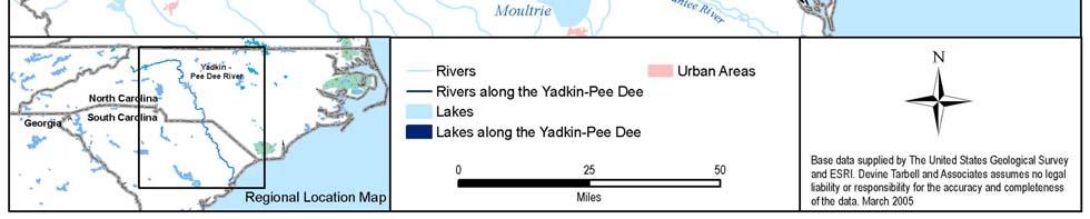
7 Figure A-1 Project location map. A-3
8 the U.S. Army Corps of Engineers (ACOE). The next four downstream developments make up the Yadkin Project (FERC No. 2197), owned by Alcoa Power Generating, Inc. (APGI 1 ). These four hydroelectric developments High Rock, Tuckertown, Narrows, and Falls are located along a 38-mile stretch of the Yadkin River (river miles [RM] 272 to ). High Rock Reservoir serves as the primary storage and water regulation facility for the lower Yadkin-Pee Dee River (APGI 2002). Progress Energy s Tillery and Blewett Falls facilities are the next two hydroelectric developments on the river, located at approximately RM 218 and 188, respectively. The North Carolina-South Carolina state line is located at RM 173, approximately 15 miles downstream of Blewett Falls Dam. Table A-1 provides the location and drainage area of each of the six FERC-licensed facilities. River flows to Progress Energy s Tillery and Blewett Falls developments are largely dependent on releases from APGI s Yadkin Project. Flow releases from APGI s Yadkin Project to Progress Energy s Tillery Development are governed by a FERC-approved agreement between the parties. This agreement requires APGI to operate in a manner that allows Progress Energy to meet its continuous flow requirements. Yadkin s seasonal operations are managed in accordance with a rule curve that guides the operation of High Rock Lake. The current rule curve, referred to as Yadkin s Operating Guides for Operation of Badin Works, is provided in Figure B-4. Table A-1 River mile locations and drainage areas of hydropower facilities. Facility River Mile Drainage Area (mi 2 ) Blewett Falls ,839 Tillery ,600 Falls Dam ,190 Narrows Dam ,180 Tucker Dam ,080 High Rock Reservoir , The FERC license for APGI s Yadkin Project expires the same date as the FERC license for the Tillery and Blewett Falls developments, April 30, River miles are measured in an upstream direction from Winyah Bay in South Carolina. Blewett Falls Dam is located 188 river miles above Winyah Bay. A-4
 are located in Montgomery and Stanly counties, four miles west of Mount Gilead, North Carolina.")
9 3.0 Description of Primary Project Works 3.1 Tillery Development The Tillery Dam and its powerhouse (see photo below) are located in Montgomery and Stanly counties, four miles west of Mount Gilead, North Carolina. The Tillery impoundment (known as Lake Tillery) extends upstream 16 miles to the tailrace of APGI s Falls Development powerhouse. Construction of the Tillery Development began in 1926 and the plant was placed in service in The facilities have operated safely and reliably for 78 years. The Tillery Development consists of a concrete gravity dam with 18 gated spillways; a four-unit indoor-outdoor powerhouse; electrical switchyard; associated auxiliary electrical and mechanical equipment; and recreational facilities located on the 16-mile-long reservoir Dams, Spillways, and Reservoirs Dams and Spillway Tillery Dam (also known as Norwood Dam) consists of approximately 1,200 ft of earthen embankment and 1,550 ft of concrete gravity structures. The concrete works include a 758-ft-long spillway consisting of a 62-ft-high ogee section, a concrete stilling basin, a 310-ft-long powerhouse intake structure, and 485-ft-long east and west non-overflow segments. The spillway at Tillery is controlled by 18 radial gates, each 34 ft wide by 24 ft high. Six of the gates can be partially operated remotely from the powerhouse control room. The other gates can be operated by means of controls located at the gates on the spillway deck. A 14-ft-wide bottom-drop trash sluice gate is located between the powerhouse intake and spillway. A-5
10 Two non-overflow structures form the abutments of the concrete gravity spillway and powerhouse structures. The 176-ft-long west bulkhead has a top width of 6 ft and maximum height of 88.5 ft. It is located between the gated spillway structure and the westerly earthen embankment. The east abutment is 308 ft long with a top width of 20 ft and a maximum height of 88.5 ft. It is located at the east end of the powerhouse intake structure and extends to natural ground on the east abutment Reservoir The Tillery Dam creates the impoundment known as Lake Tillery. The impoundment extends approximately 16 miles to the tailwater of APGI s Falls Development. At the normal maximum reservoir elevation of ft 3, Lake Tillery has a maximum depth of about 72 ft and a surface area of approximately 5,697 acres. The lake is widely used by the public for boating, fishing, swimming, camping, and other recreational activities. The lake has approximately 118 miles of shoreline (Carolina Power & Light [CP&L] 2001) with approximately 55 percent being in residential or commercial development. The Tillery reservoir currently has a FERC-licensed usable storage capacity of 84,150 ac-ft at the normal water surface elevation of ft 4. Two municipal water supply intakes are located on Lake Tillery (see Figure E3-5 in Exhibit E3, Water Use and Quality, for intake locations). These intakes are for the Town of Norwood and for Montgomery County. The intake structure for the Norwood Water Treatment Plant is located on the west shoreline, directly east of the Town of Norwood and approximately 2.5 miles upstream of Tillery Dam. The intake is located downstream of the Cedar Creek tributary arm of the lake. The intake pipe is situated approximately 25 ft below the normal reservoir level. The Montgomery County Water Treatment Plant s water intake is located on the east shoreline of Lake Tillery approximately 500 yards upstream of the Tillery intake structure and dam (Figure E3-5). Two intakes on the east shoreline serve the water treatment plant. Only one intake is used at any one time. The lower intake pipe is located at elevation 255 ft or 22 ft below the normal reservoir water surface elevation. It can be operated when the lake is too low to permit use of the upper intake Powerhouse The Tillery powerhouse is a concrete, indoor-outdoor structure containing four generating units, each with a dedicated penstock and headgate, and Moody-type draft tubes. Each turbine drives a direct-connected vertical-shaft generator. The turbine flow exits directly to the Pee Dee River. The gross head is 72 ft. The powerhouse is integral with the dam. 3 4 All elevations are NAVD 88 datum. This usable storage capacity is based on the maximum drawdown of 22 ft allowed under the current license. In practice, Progress Energy has, by informal agreement with lakeshore owners, agreed to try to limit drawdowns to 1 to 2 ft during prime recreational periods. A-6
11 3.1.3 Turbines and Generators Turbines The Tillery Development houses three Francis turbines and one fixed-blade propeller turbine. The powerhouse also contains a small Francis auxiliary turbine for driving a house generator. A summary of the turbine-generator equipment at the Tillery Development is presented in Table A-2. Table A-2 Summary of Tillery turbine-generator equipment. Unit 1 Unit 2 Unit 3 Unit 4 Auxiliary Turbine: Manufacturer I.P. Morris I.P. Morris I.P. Morris Allis-Chalmers J. Leffel Type Vertical, Francis Vertical, Francis Vertical, Francis Vertical, Propeller Vertical, Francis Rated Power (hp) 31,100 25,600 31,100 33, Rated Head (ft) Speed (rpm) Discharge Capacity (cfs) 4,456 3,627 4,456 5, Generator: Manufacturer Allis-Chalmers Allis-Chalmers Allis-Chalmers Westinghouse Westinghouse Rated p.f Rating (kva) 27,500 22,500 27,500 27, Units 1 through 4 have headcovers that serve as the pressure boundary for the interface with the powerhouse. For all four units, water is delivered from the reservoir and is discharged from the turbines to a symmetrical, Moody-type draft tube with a high cone. The cone extends from the floor of the draft tube to just below the turbine runner. The purpose of the high cone is to prevent formation of draft tube vortices and to help mitigate whirl coming off the runner. The overall purpose of the draft tube is to recover velocity head at the runner discharge. This configuration of draft tube allows a relatively short distance from draft tube exit to the vertical centerline of the generating unit, thereby reducing powerhouse size. For Units 1 through 3, the turbine distributor centerline is set approximately 7 ft above the normal tailwater level of ft. Unit 4 turbine distributor centerline is also set at the same elevation as Units 1 through 3 but the five fixed blades of this axial flow, propeller-type turbine are at a centerline elevation of approximately 204 ft. This setting reduces the likelihood of cavitation forming on the turbine blades or in the clearance between the blades and the turbine discharge ring Generators The generators for Units 1, 2, and 3 are Allis-Chalmers three-phase, 60-cycle units. Units 1 and 3 are rated at 27,500 kva at 0.8 p.f., 22 MW, and 13,800 V. Unit 2 is rated at 22,500 kva at 0.8 p.f., 18 MW, and 13,800 V. Unit 4 is a Westinghouse three-phase, 60-cycle generator rated at 27,500 kva at 0.8 p.f., 22 MW, and 13,800 V. A summary of the generator equipment is provided in Table A-2. The generators for Units 1 through 3 were rewound in 1966, and Unit 4 was rewound in The house generator is rated 563 kva, 550 volts AC. All four main generators are cooled using water-to-air heat exchangers. The fire protection system is CO2. All four units are provided with static exciters. The generator voltage of 13.8 kv is A-7
12 stepped-up to a transmission voltage of 115 kv at the station transformers located on the powerhouse deck Accessory Electrical Equipment Main Power System The Tillery power system is designed with two parallel three-phase, step-up transformers dedicated to each of the four main units. Each unit has a 115 kv circuit breaker on the high side of the step-up transformers for protection and synchronizing. Each unit is provided with static excitation, voltage regulation, and protective relay system Electrical Auxiliary Systems Unit control logic and metering are integrated within a programmable logic controller (PLC) for each unit. This facilitates the monitoring and operation of the units from either the local control room or remotely. Primary station auxiliary power is provided by a 550 volt AC system. Each unit auxiliary transformer feeds a shared ring bus. The house generator, noted above, feeds into this 550-volt ring bus. Station control power is provided by a battery-backed DC system Accessory Mechanical Systems Typical auxiliary mechanical systems include cooling water, lube oil, HVAC, and governor hydraulic system. The original low-pressure governor servomotors and associated governor systems were upgraded in 1991 with new high-pressure equipment. These high-pressure systems are interfaced with the PLC systems noted above. The original low-pressure hydraulic system is still used for the governor function on Unit 4. A 150-ton gantry crane, including various auxiliary hooks, is located outdoors to facilitate maintenance on the units Proposed Modifications to the Project Works of the Tillery Development Progress Energy has no current plans to upgrade the existing power generation equipment. Modification of Project facilities and/or operations will occur over the term of the next license as a result of implementation of the following proposed environmental resource enhancements. Water Quality - Progress Energy has developed a detailed program for meeting State of North Carolina water quality dissolved oxygen (DO) standards at Tillery within three years of issuance of a new license. Depending on the preferred DO enhancement technology, Project operation and facilities may be subject to minor modifications. If facility modifications are required, revised Exhibit F drawings will be submitted to FERC for approval. Fish Passage - Progress Energy, in consultation with resource agencies, has proposed a fish protection and passage plan that will consist of a phased approach based on a multi-year program during the term of the next license period in order to meet the goals and objectives of the Pee Dee River Diadromous Fish Restoration Plan. Implementation of this plan may result A-8

13 in changes to Project facilities (e.g., construction of upstream fish passage facilities) and operations (e.g., diverting flow through fishways). After facility modifications are completed, revised Exhibit F drawings will be submitted to FERC for approval. 3.2 Blewett Falls Development Construction of the Blewett Falls Development began in Financial problems prevented the original builders from completing the Project. The Yadkin River Power Company acquired the rights to the Blewett Falls Development and finally brought the plant into service in June Progress Energy acquired the Yadkin Power Company in The Blewett Falls Dam and powerhouse (see photo above) are located at RM 188 approximately 15 miles upstream of the North Carolina-South Carolina state line. The Blewett Falls Development consists of a concrete gravity ungated spillway with 4-ft flashboards, easterly and westerly earthen embankments, a forebay canal, concrete intake, powerhouse with six units, a tailrace which rejoins the Pee Dee approximately 900 ft downstream of the dam, and a 12-mile-long reservoir Dams, Spillways, and Reservoirs Dam and Spillway The Blewett Falls Dam is a 3,168-ft-long structure consisting of a 1,700-ft-long earthen embankment and a 1,468-ft-long concrete spillway and abutments. The 300-ft-long powerhouse intake is separated from the spillway by a portion of the westerly earthen embankment. The spillway is a concrete gravity ogee-type structure topped by 4 ft of wooden flashboards which are designed to fail at about 3 ft of overtopping. The permanent concrete crest is at elevation A-9
14 173.2 ft. Training walls adjacent to the spillway have a top elevation of ft. Additional concrete gravity overflow sections are adjacent to the spillway and are approximately 150 ft long with a top elevation of ft. Earthen embankments with concrete core walls are located on both ends of the spillway. The easterly earthen embankment is approximately 870 ft long with a top elevation of ft. The westerly earthen embankment is approximately 850 ft long with a top elevation of ft Reservoir The Blewett Falls Dam creates the 12-mile-long Blewett Falls impoundment. The normal pool elevation is ft. The surface area of the lake at the normal operating pool is approximately 2,866 acres. The Blewett Falls shoreline is largely undeveloped. The lake is available to the public for boating, fishing, and recreation. The lake shoreline is largely undisturbed, and the lake supports good populations of game fish, especially crappie and largemouth bass. The Blewett Falls reservoir has a usable storage of 30,893 ac-ft, corresponding to the 17 ft of drawdown currently allowed by its FERC license. Under normal daily operations, the reservoir fluctuates 2 to 4 ft to regulate flows coming from Lake Tillery and the Rocky River. Two municipal water supply intakes are located in Blewett Falls Lake, one each for Anson and Richmond counties (see Figure E3-6 in Exhibit E3, Water Use and Quality, for intake locations). The intake structure for the Anson County Water Treatment Plant is located on the west shoreline in the lower portion of Blewett Falls Lake in the Smith Creek arm of the lake approximately 1.5 miles upstream of the dam (Figure E3-6). The invert for this intake is at elevation ft. Progress Energy notifies the water treatment plant if they will be drawing down the reservoir below ft. The Richmond County intake structure is located on the east shoreline of Blewett Falls Lake less than 1,000 yards upstream from the dam (Figure E3-5) Intake and Powerhouse The 300-ft-long Blewett Falls powerhouse is a concrete gravity structure with a brick-masonry and steel superstructure. It is located at the downstream end of an approximately 300-ft-long forebay canal. The gross head is approximately 52 ft. The Blewett Falls powerhouse contains six generating units, each with its own penstock. Each of the turbine units drive a direct-connected, horizontalshaft generator. The turbines discharge via steel-conical draft tubes into a 900-ft-long tailrace channel which reconnects to the Pee Dee River. Flows are delivered from the forebay canal to an intake structure containing headgates, trashracks, and penstocks. The intake delivers water to the six penstocks which house the turbine units. Two small auxiliary units are also contained in the powerhouse. On the downstream side of the powerhouse, a fishing platform extends across the entire building providing ADA-accessible tailwater fishing. A-10
15 3.2.3 Turbines and Generators Turbines The six Blewett generating units were commissioned in June of Each generator is driven by two identical hydraulic turbines operating in tandem. Each turbine consists of two runners; therefore, each unit contains four separate runners. This configuration is referred to as a quadrunner alignment. Each of the 12 hydraulic turbines, manufactured by S. Morgan Smith, is of a horizontal-shaft, double-opposed runner, single-discharge configuration. A summary of the generating equipment at the Blewett Falls Development is presented in Table A-3. Table A-3 Turbine: Summary of Blewett Falls turbine-generator equipment. Unit 1 Unit 2 Unit 3 Unit 4 Unit 5 Unit 6 Manufacturer S. Morgan S. Morgan S. Morgan S. Morgan S. Morgan S. Morgan Smith Smith Smith Smith Smith Smith Rated Power (hp) 5,350 5,350 5,350 6,400 6,400 6,400 Rated Head (ft) Speed (rpm) Maximum Discharge Capacity (cfs) 1,351 1,351 1,351 1,715 1,715 1,715 Generator: Manufacturer General General General General General General Electric Electric Electric Electric Electric Electric Rated p.f Power Rating (kva) 4,000 4,000 4,000 6,500 6,500 6,500 The units are typically synchronized to the system and loaded to best-efficiency output when operated. For Units 1 to 3, this occurs at a generator output of approximately 3,500 kw each at the normal operating gross head of approximately 52 ft. The corresponding best-efficiency load for Units 4 to 6 is approximately 4,200 kw. The units are run at maximum output during periods of high inflows. Water passing through the intake works is directed to the two turbines for each unit via a short 17-ftdiameter section of steel penstock. This short section of penstock attaches to an 18-ft-diameter pressure case, which houses both turbines. The pressure boundary for the interface with the powerhouse is achieved by a single headcover per unit. The turbine discharge is then directed to the tailrace by a single draft tube per turbine (therefore two draft tubes per unit). The turbine shaft centerline of each generating unit is located approximately 20 ft above the normal tailwater level of 126 ft. The draft tube allows recovery of head which would otherwise be lost. This does, however, significantly reduce the pressure on the low-pressure side of the turbine runners. During the late 1980s and early 1990s, the turbines were refurbished and new stainless steel runners were installed. When the turbines were refurbished, new wicket gate and wicket gate bushings were installed. Also, new wicket gate pins made from stainless steel were installed to address corrosion problems. New draft tubes were installed on all units in the early 1990s. Originally, there were two hydraulic turbine-driven DC generators that provided the field for excitation of the main generators. These units were retired when the new static exciters were A-11
16 installed in 1985 to The 4-ft-diameter penstocks, turbine pressure cases and at least part of the turbines remain Generators The original six generators were built by General Electric and are all 3-phase, 60-cycle, directconnected, indoor-type, horizontal-shaft generators. The generators for Units 1, 2, and 3 are nameplate rated at 3,200 kw with a p.f. of 0.8, 4,800 V at full load. They are 164 rpm with 396 coils. Generators for Units 4, 5, and 6 indicate ratings of 5,000 kw at a p.f. of A summary of the generators is provided in Table A-3. Unit 1 generator was rewound in 1982, Units 2 and 4 were rewound in 1990, Unit 3 was rewound in 1986, Unit 5 was rewound in 1975, and Unit 6 was rewound in Field current for each generator is provided by respective static excitation systems Accessory Electrical Equipment Main Power System The electrical main power system for Blewett Falls is such that the generators are protected and synchronized to the system with indoor, medium-voltage, vacuum switchgear breakers. Station output from all units is stepped up to the 115 kv transmission system using three single-phase, indoor, water-cooled, transformers operating as a single bank. The transformers are provided with a water spray fire protection system. Current limiting reactors are installed between the step up transformer bank and the switchgear bus. Control design is such that units can be started from the plant control room. The units have black start capability. A single 115 kv circuit breaker is located electrically on the high side of the step-up transformer bank. This breaker is located physically within the powerhouse in an upstairs high tension room Electrical Auxiliary Systems AC and DC auxiliary power systems are typical, except for power to various DC motors. A 250 VDC rectifier system, with 480 VAC input, has been installed for feeding power to crane motors and flood pumps Accessory Mechanical Systems Typical auxiliary mechanical systems are provided for cooling water, lube oil, HVAC, and governor hydraulics. The original governors were modernized and converted to gate positioners in the 1980s. Unit speed is now regulated by the electrical inertia of the large power system grid once the units have been synchronized. The gate positioners are then used only to control turbine power output by varying wicket gate opening. A 40-ton crane is located within the powerhouse s generator room to facilitate teardowns and maintenance. A-12
17 3.2.6 Proposed Modifications to the Project Works of the Blewett Falls Development Progress Energy has no plans to modify the existing power generation equipment. However, modification of Project facilities and/or operations will occur over the term of the next license as a result of implementation of the following proposed environmental resource enhancements. Water Quality - Progress Energy has proposed a detailed program for meeting State of North Carolina water quality DO standards at Blewett Falls within three years of issuance of a new license. Depending on the outcome of the different enhancement options analyzed, Project operations and facilities may be subject to minor modifications. If facility modifications are required, revised Exhibit F drawings will be submitted to FERC for approval. Fish Passage - Progress Energy, in consultation with resource agencies, has proposed a fish protection and passage plan that will consist of a phased approach based on a multi-year program during the term of the next license period in order to meet the goals and objectives of the Pee Dee River Diadromous Fish Restoration Plan. Implementation of this plan will result in changes to Project facilities (e.g., construction of upstream fish passage facilities) and operations (e.g., diverting flow through fishways). After facility modifications are completed, revised Exhibit F drawings will be submitted to FERC for approval. A-13
18 4.0 Description of Other Project Facilities 4.1 Transmission Tillery Transmission Facilities An outdoor switchyard is located within the Project Boundary just east of the powerhouse. The switchyard operates at 115 kv. It is arranged, electrically, in a single-bus, single-breaker configuration. Each of the four generating-unit, step-up transformers feed a single 115 kv bus through dedicated circuit breakers. Each of the four 115 kv transmission lines that exit the switchyard has its own circuit breaker Blewett Falls Transmission Facilities A single 115 kv line exits the Blewett Falls powerhouse and feeds into a small outdoor switchyard located just north of the powerhouse within the Project Boundary. This yard contains 115 kv circuit breakers for three circuits: one for an incoming line from adjacent combustion turbines, and two for transmission lines that provide ties to other switchyards that are part of Progress Energy s system. 4.2 Recreation Facilities The Project is located in the Uwharrie Lakes region of south-central North Carolina. The Uwharrie Lakes consist of six manmade lakes created as a result of the construction of hydroelectric facilities, including the Tillery and Blewett Falls developments. The Uwharrie Lakes provide a variety of recreational opportunities including boating, canoeing, swimming, fishing, and most other water sports. Detailed discussions regarding recreation resources and the facilities present at each lake are provided in Exhibit E Tillery Recreation Facilities Progress Energy leases all of its public access areas to the North Carolina Wildlife Resources Commission (NCWRC), which provides operation and maintenance for the recreation facilities. Public Boat Access - Lake Tillery has four public access areas 5 - the Lilly s Bridge boating access area which includes two boat ramps, approximately one mile upstream of the dam, the Swift Island boating access area which offers a large parking area and two paved boat ramps, the Stony Mountain boating access area which offers a large parking lot and two paved boat ramps, the Norwood boating access area which offers two paved ramps and a parking area. Developed Fishing Area - The Lilly s Bridge fishing pier is located directly across from the Lilly s Bridge Access Area. Canoe Portage - Progress Energy maintains a canoe portage located on the west shore of the dam. There are numerous privately-operated recreation facilities and marinas on Lake Tillery as well. 5 Public access to the lake is also provided at Morrow Mt. State Park. This access is managed by the State of North Carolina, Division of Parks and Recreation. A-14
19 4.2.2 Blewett Falls Recreation Facilities Progress Energy also leases all of its public access facilities on Blewett Falls Lake to the NCWRC. Public Boat Access - A total of two public access areas (Pee Dee and Grassy Islands) are located at Blewett Falls Lake. There is also a small developed access site at the put-in area at the end of the canoe portage route just below the dam. This site has a boat ramp and a gravel parking area. Grassy Islands offers boating access via a paved ramp and has a small parking area. The Pee Dee recreation area offers boating access and a large parking area. Developed Fishing Area - Blewett Falls Development provides an accessible fishing pier for the general public and persons with disabilities at the tailrace just below the powerhouse. This concrete fishing platform is attached to the powerhouse, and was cooperatively built with the NCWRC. A paved parking area and walkway allows for easy access to the site. Canoe Portage - Progress Energy maintains a canoe portage located on the eastern shore of the dam Proposed Recreation Facilities Since the issuance of the Initial Consultation Document (February 2003) and Joint Public Meeting (March 2003), Progress Energy has worked closely with stakeholders to evaluate potential protection, mitigation and enhancement (PM&E) measures to be implemented for the future operation of the Tillery and Blewett Falls developments. After the completion of stakeholder consultation and recreational studies (including a recreation survey), Progress Energy analyzed the Project record and study findings to determine the need for recreational PM&E measures. Having completed this evaluation, Progress Energy proposes certain recreational PM&E measures for the Tillery and Blewett Falls developments. The PM&E measures will provide the public with additional access and improved recreational opportunities at the Project during the next license term. According to the recreation studies performed as part of relicensing, overcrowding at public access areas was not generally perceived as an issue of concern by recreational users visiting facilities at either of the Project lakes. Issues identified by recreational users were more related to misuse of the facilities and less to boater use levels. Detailed site plans for recreational enhancements, the proposed implementation dates, and the responsibilities of the involved parties will be filed with FERC after issuance of the new license Tillery Development Progress Energy proposes to make several improvements at four public boating access areas located on Lake Tillery: the Lilly s Bridge, Swift Island, Norwood, and Stony Mountain access areas. Generally, improvements to these areas include the addition of public sanitary facilities, trash receptacles, improved parking areas, additional public information signage, and updating the Project public information kiosks. Progress Energy proposes to relocate the existing informal public boating access area located in the tailrace immediately below the Tillery Plant (Figure E7-1). Progress Energy, in consultation and partnership with the NCWRC, will develop and construct a new public boating access area located at the mouth of Clarks Creek, approximately one-half mile below the power plant and one-quarter mile from the current access area. Public access to the Clarks Creek boating access area will be from the A-15
20 power plant access road (i.e., Tillery Dam Road) which is located off State Road 1103 and NC Highway 731. The boating access area will have a gravel parking lot with designated Americans with Disabilities Act (ADA) parking places. Progress Energy proposes to work with the NCWRC in co-funding with matching dollars for the construction of a boat house and access ramp for use by enforcement personnel on Lake Tillery. This facility will permit the NCWRC to respond more effectively to boating emergencies on the lake and serve as a central point for safe boating enforcement activities on the lake. The proposed location is on the main lake side of the Project lands on the peninsula located adjacent to and south of the Stony Mountain boating access area (Figures E7-1 and E7-5). Progress Energy will consult with the NCWRC on effective means to discourage public use of the informal public access area at State Roads 1740 and 1745, locally known as the Steel Bridge Area (see Figure E7-1). The development of the public fishing pier at the nearby Stony Mountain boating access area will provide additional public fishing opportunities that may be eliminated with the closure of this informal access area Blewett Falls Development Progress Energy proposes to build a new public boating access area on the Richmond County side of Blewett Falls Lake within five years of issuance of the new license, if a suitable site can be identified. Suitability will depend upon identifying a buildable site and obtaining the necessary access across private lands. The new boating access area would be located in the lower lake area in the general vicinity of the opposite shore of the existing Pee Dee access area located on the Anson County side of the lake (Figure E7-2). Progress Energy will work with local county officials and interested landowners to site the new public boating access area. Progress Energy proposes to include several improvements at the two public boating access areas currently located on Blewett Falls Lake. At the Pee Dee Access Area, Progress Energy will provide public sanitary facilities and trash receptacles; update the public information signage including a new Project information kiosk; and improve parking facilities for vehicles and boat trailers. At the Mountain Creek (Grassy Islands) Access Area, Progress Energy will provide trash receptacles; update the public information signage including a new Project information kiosk; and improve parking facilities for vehicles and boat trailers. At both sites, Progress Energy will also work with the NCWRC to improve the boat ramps to permit effective boating accessibility over the range of lake levels proposed for the new license term. Progress Energy proposes to upgrade the canoe portage facility located on the east shoreline of Blewett Falls Lake at the dam to applicable state recreational standards. Progress Energy will provide an electronic link on its external Company internet web site that will allow the public to access real-time Pee Dee River streamflow data at the USGS Rockingham gage station (USGS Gage No ). A-16
21 5.0 Federal Lands Within the Project Boundary The Project Boundary for the Tillery Development and the Blewett Falls Development are identified on the Project drawings located in Exhibit G. There are no federal or Tribal lands located within the Project Boundary. A-17
22 6.0 References Alcoa Power Generating, Inc Yadkin River Hydroelectric Project FERC No NC. Project Relicensing Initial Consultation Document. September Alcoa Power Generating, Inc., Yadkin Division, Badin, North Carolina. ASU North Carolina s Central Park: Assessing Tourism and Outdoor Recreation in the Uwharrie Lakes Region. Appalachian State University, September Code of Federal Regulations (CFR) at 18 CFR 4.51(b). Carolina Power & Light CP&L A Progress Energy Company. Shoreline Management Plan for the Tillery Hydroelectric Project (FERC No. 2206). Submitted by Carolina Power & Light A Progress Energy Company, December 30, Prepared by The Louis Berger Group, Inc. Gorp Destinations: Pee Dee National Wildlife Refuge. [Online] URL: (Accessed May 24, 2002.) National Park Service National Park Service Nationwide Rivers Inventory. [Online] URL: (Accessed June 17, 2002.) North Carolina Division of Parks and Recreation Morrow Mountain State Park. [Online] URL: (Accessed June 18, 2002.) North Carolina Division of Water Quality Yadkin-Pee Dee River basin wide water quality management plan. May North Carolina Department of Environmental Natural Resources, Division of Water Quality, Raleigh, North Carolina. Progress Energy Initial Consultation Document. Yadkin-Pee Dee River Project FERC No Submitted by Progress Energy, Raleigh, North Carolina, February U.S. Department of the Interior Mammals, Amphibians and Reptiles of the Pee Dee National Wildlife Refuge. RF May A-18
FINAL LICENSE APPLICATION Exhibit A Description of Project
 FINAL LICENSE APPLICATION Exhibit A Description of Project PacifiCorp Portland, Oregon April 2004 Copyright 2004 by PacifiCorp Reproduction in whole or in part without the written consent of PacifiCorp
Project Description - 1 -
 Project Description The Mother Ann Lee Hydroelectric Station is located at Lock and Dam 7 on the Kentucky River. This dam is part of a system of 14 lock and dams installed on the Kentucky River between
Appendix G Aquilla Lake Pool Rise Recreational Resources
 Appendix G Aquilla Lake Pool Rise Recreational Resources 1. INTRODUCTION The purpose of this appendix is to document the impacts of a 2.5 ft (Alternative A), 4.5 ft (Alternative B), and 6.5 ft. (Alternative
McNary Northshore Fishway Hydro Project. History & Lessons Learned
 McNary Northshore Fishway Hydro Project History & Lessons Learned May 6, 2017 21 th Annual TECHNICAL SEMINAR Machines, Maintenance, and Management: Keeping Hydro Facilities Up and Running History & Lessons
CUSHMAN HYDROELECTRIC PROJECT. Pat McCarty, Generation Manager
 CUSHMAN HYDROELECTRIC PROJECT Pat McCarty, Generation Manager AGENDA A picture tour of Cushman Relicense history Relicense requirements Fisheries Flows & reservoir elevations Cultural/historical resources
Sano Milti Khola Hydropower Project, Fulasi VDC, Ramechhap (3 MW)
") Sano Milti Khola Hydropower Project, Fulasi VDC, Ramechhap (3 MW) Monthly Progress Report Prepared by : Sano Milti Khola Hydropower Limited www.smi.com.np smi.investment.limited@gmail.com Date : June,
Sano Milti Khola Hydropower Project, Fulasi VDC, Ramechhap (3 MW) Monthly Progress Report Prepared by : Sano Milti Khola Hydropower Limited www.smi.com.np smi.investment.limited@gmail.com Date : June,
STRUCTURE 5A PURPOSE
 STRUCTURE 5A This structure is a six unit pumping plant located on the south side of U.S. Highway 441 and Canal 51 (West Palm Beach Canal) between the canal and the borrow canals of Levees 7 and 40 about
NORTHERN INDIANA PUBLIC SERVICE COMPANY NORWAY AND OAKDALE HYDRO ELECTRIC PLANTS MONTICELLO, INDIANA
 NORTHERN INDIANA PUBLIC SERVICE COMPANY NORWAY AND OAKDALE HYDRO ELECTRIC PLANTS MONTICELLO, INDIANA INTRODUCTION: NIPSCO is the proud owner of two Hydro Electric Plants located near Monticello, Indiana.
ALBENI FALLS DAM AND LAKE PEND OREILLE
 ALBENI FALLS DAM AND LAKE PEND OREILLE Fall Public Meeting 237 237 237 217 217 217 200 200 200 0 0 0 163 163 163 131 132 122 Aug. 7, 2017 255 255 255 239 65 53 80 119 27 252 174.59 83 36 118 110 135 120
SNOHOMISH COUNTY PUBLIC UTILITY DISTRICT NO.1. Your Northwest renewables utility
 SNOHOMISH COUNTY PUBLIC UTILITY DISTRICT NO.1 Your Northwest renewables utility May 17, 2013 VIA ELECTRONIC FILING Kimberly D. Bose, Secretary Federal Energy Regulatory Commission (FERC) 888 First Street
STRUCTURE S-13. Revised 2/21/02
 STRUCTURE S-13 This structure is a pumping station with a gated spillway which can control flows which bypass the pumps. The structure is located in Canal 11 (South New River Canal) about 300 feet west
Exhibit 1. Background. Authorizing Legislation
 Background Authorizing Legislation The Boulder Canyon Project Act (43 U.S.C. 617, et seq.), enacted by the U.S. Congress in 1928 (The 1928 Act), authorized the Secretary of the Interior to spend up to
LAKE CHELAN ANNUAL FLOW AND WATER TEMPERATURE REPORT Final
 LAKE CHELAN ANNUAL FLOW AND WATER TEMPERATURE REPORT 2013 LICENSE ARTICLES 405 & 408 Final LAKE CHELAN HYDROELECTRIC PROJECT FERC Project No. 637 April 30, 2014 Public Utility District No. 1 of Chelan
Overview of hydro electric dams and how they work Provide background on basic principles of hydropower and its history. Explain features that all
 Overview of hydro electric dams and how they work Provide background on basic principles of hydropower and its history. Explain features that all hydro power dams have and compare the design of Revelstoke
WOLVERINE TO BHP JANSEN NEW TRANSMISSION LINE PROJECT FALL 2017
 WOLVERINE TO BHP JANSEN NEW TRANSMISSION LINE PROJECT FALL 2017 TODAY WE LL TALK ABOUT Our challenges and how we re meeting them Why we re building this project Our planning process and considerations
Alberta Electric System Operator Saleski Transmission Project Needs Identification Document
 Decision 2013-127 Alberta Electric System Operator Saleski Transmission Project Needs Identification Document ATCO Electric Ltd. Saleski 901S Substation and 144-kV Transmission Line 7L142 Facility Application
Decision on Merced Irrigation District Transition Agreement
 California Independent System Operator Corporation Memorandum To: ISO Board of Governors From: Karen Edson, Vice President Policy & Client Services Date: March 13, 2013 Re: Decision on Merced Irrigation
CHAPTER 25. SUBSTANTIVE RULES APPLICABLE TO ELECTRIC SERVICE PROVIDERS.
 25.211. Interconnection of On-Site Distributed Generation (DG). (a) (b) (c) Application. Unless the context indicates otherwise, this section and 25.212 of this title (relating to Technical Requirements
ENERGY STRATEGY FOR YUKON. Independent Power Production Policy
 ENERGY STRATEGY FOR YUKON Independent Power Production Policy May 20, 2014 Page 2 of 11 BACKGROUND The Government of Yukon released the Energy Strategy for Yukon in January 2009. The strategy sets out
Generator Rebuild and Unit Refurbishment for the Wells Hydroelectric Project. NWHA Spokane October 30, 2014
 Generator Rebuild and Unit Refurbishment for the Wells Hydroelectric Project NWHA Spokane October 30, 2014 0 The Wells Project WELLS Chief Joseph Rocky Reach East Wenatchee Wells Dam Location Columbia
Merger of the generator interconnection processes of Valley Electric and the ISO;
 California Independent System Operator Corporation Memorandum To: ISO Board of Governors From: Karen Edson Vice President, Policy & Client Services Date: August 18, 2011 Re: Decision on Valley Electric
Rebuilding A 70-YearOld Rural. Alaska Hydro. David Lockard AEA
 Pelican Hydro Upgrade: Rebuilding A 70-YearOld Rural Alaska Hydro David Lockard AEA The Pelican Boardwal k Pelican Background and History Located on the NW side of Chichagof Island, SE Alaska 100 miles
Memorandum. This memorandum requires Board action. EXECUTIVE SUMMARY
 California Independent System Operator Memorandum To: ISO Operations (MRTU) Committee From: Armando J. Perez, Director of Grid Planning cc: ISO Board of Governors ISO Officers Date: April 29, 2005 Re:
5 June 12, 2013 Public Hearing APPLICANT: BARTON HERITAGE, LLC T/A SANDBRIDGE BEACH BUGGIES PROPERTY OWNER: LOWER 40, LLC
 REQUEST: Conditional Use Permit (motor vehicle rentals low speed vehicles) ADDRESS / DESCRIPTION: 3713 Sandpiper Road 5 June 12, 2013 Public Hearing APPLICANT: BARTON HERITAGE, LLC T/A SANDBRIDGE BEACH
Decision D ATCO Electric Ltd. Decommissioning of Transmission Line 6L82
 Decision 21447-D01-2016 August 23, 2016 Decision 21447-D01-2016 Proceeding 21447 Application 21447-A001 August 23, 2016 Published by the: Fifth Avenue Place, Fourth Floor, 425 First Street S.W. Calgary,
Implementing a Microgrid Using Standard Utility Control Equipment
 Implementing a Microgrid Using Standard Utility Control Equipment Tom Fenimore Duke Energy Andy Gould and Larry Wright Schweitzer Engineering Laboratories, Inc. Copyright Duke Energy and SEL 2016 Overview
Kettle River Transmission Project
 April 2012 Why are you receiving this project information package? New transmission facilities are needed in the Fort McMurray area. ATCO Electric has been directed by the Alberta Electric System Operator
STH 60 Northern Reliever Route Feasibility Study Report
 #233087 v3 STH 60 Northern Reliever Route Feasibility Study Report Washington County Public Works Committee Meeting September 28, 2016 1 STH 60 Northern Reliever Route Feasibility Study Hartford Area Development
Appendix E Water Supply Modeling
 Supply Modeling Modesto Irrigation District Treatment Plant Expansion Project Modeling I. Introduction The Modesto Irrigation District (MID) is situated adjacent to and north of the Tuolumne River. Over
Seabrook Substation Reliability Improvement Project
 New England Division Seabrook Substation Reliability Improvement Project 1. Project Summary Description Seabrook Substation is critical to ISO-New England as a Pool Transmission Facility, to grid availability
City of Palo Alto (ID # 6416) City Council Staff Report
 City Council Staff Report") City of Palo Alto (ID # 6416) City Council Staff Report Report Type: Informational Report Meeting Date: 1/25/2016 Summary Title: Update on Second Transmission Line Title: Update on Progress Towards Building
City of Palo Alto (ID # 6416) City Council Staff Report Report Type: Informational Report Meeting Date: 1/25/2016 Summary Title: Update on Second Transmission Line Title: Update on Progress Towards Building
/ Planning and Zoning Staff Report Lonestar Land, LLC. - Rezone, RZ
 / Planning and Zoning Staff Report Lonestar Land, LLC. - Rezone, RZ2018-0019 Hearing Date: October 18, 2018 Development Services Department Applicant: Lonestar Land, LLC. Representative: Lance Warnick
The Magazine of the North American Hydroelectric Industry HYDRO REVIEW. NHA Annual Conference details pg. 69
 March 2012 www.hydroworld.com The Magazine of the North American Hydroelectric Industry HYDRO REVIEW NHA Annual Conference details pg. 69 Rehabilitation What began as a unit inspection at a vintage hydroelectric
Bohn to Kettle River Transmission Project
 April 2012 Why are you receiving this project information package? New transmission facilities are needed in the Fort McMurray area. ATCO Electric has been directed by the Alberta Electric System Operator
INTERCONNECTION STANDARDS FOR CUSTOMER-OWNED GENERATING FACILITIES 25 kw OR LESS PUBLIC UTILITY DISTRICT NO. 1 OF CHELAN COUNTY
 INTERCONNECTION STANDARDS FOR CUSTOMER-OWNED GENERATING FACILITIES 25 kw OR LESS PUBLIC UTILITY DISTRICT NO. 1 OF CHELAN COUNTY Table of Contents Chapter 1. Purpose and scope. Pg 3 Chapter 2. Application
Overview of State Distributed Generation Interconnection Rules
 Overview of State Distributed Generation Interconnection Rules Presentation to EPA CHP Webinar Series June 26, 2008 Wayne Shirley Director The Regulatory Assistance Project 50 State Street, Suite 3 Montpelier,
RULE 21 GENERATING FACILITY INTERCONNECTION APPLICATION SMUD s Distribution System - (SMUD FORM 2655)
") - (SMUD FORM 2655) A. Applicability: This Generating Facility Interconnection Application (Application) shall be used to request the interconnection of a Generating Facility to Sacramento Municipal Utility
- (SMUD FORM 2655) A. Applicability: This Generating Facility Interconnection Application (Application) shall be used to request the interconnection of a Generating Facility to Sacramento Municipal Utility
State Regulatory Affairs and Local Relations Update. ATC Customer Meeting November 19, 2009
 State Regulatory Affairs and Local Relations Update ATC Customer Meeting November 19, 2009 Project Certification Steve Parker Manager State Regulatory Affairs CA/CPCN Applications (Filed/Ordered/Under
Quonset Business Park
 Quonset Business Park September 28, 2010 Katherine Trapani Planning Manager Quonset Development Corporation Quonset Business Park 3,160 Total Acres 168 Companies 8,842 Jobs QDC Input into URI Study Water
Rocky Reach Bridge Crane Repair. Commission Presentation February 1, 2016
 Rocky Reach Bridge Crane Repair Commission Presentation February 1, 2016 Overview Rocky Reach Bridge Crane Rehab Main Hoist Drum Inspections Impacts to Projects and Plant Operations Alternatives Considered
Decision D ATCO Electric Ltd. Decommissioning of Transmission Line 6L79. October 18, 2016
 Decision 21481-D01-2016 October 18, 2016 Alberta Utilities Commission Decision 21481-D01-2016 Proceeding 21481 Application 21481-A001 October 18, 2016 Published by the: Alberta Utilities Commission Fifth
Alberta Electric System Operator Needs Identification Document Application. Mowat 2033S Substation
 Decision 21781-D01-2016 Alberta Electric System Operator Needs Identification Document Application Facility Applications September 7, 2016 Alberta Utilities Commission Decision 21781-D01-2016: Alberta
Project Location. Purpose and Need for Action. File Code: 1950 Date: September 14, Dear Interested Party,
 United States Department of Agriculture Forest Service Idaho Panhandle National Forests Sandpoint Ranger District 1602 Ontario Street Sandpoint, ID 83864 File Code: 1950 Date: September 14, 2016 Dear Interested
Table Station Elements
 The overall layout of the station in the Preferred Alternative (Modified Alternative 2) is described in Table 7.5-1. Table 7.5-1 Station Elements Ground Level Mezzanine Level Platform Level Existing/Upgraded
*iiiii. May 31, 2017 VIA ELECTRONIC FILING
 *iiiii. PUBLIC UTILITY DISTRICT NO. I of CHELAN COUNTY P.O. Box 1231, Wenatchee, WA 98807-1231 327 N. Wenatchee Ave., Wenatchee, WA 98801 (509) 663-8121 Toll free 1-888-663-8121 www.chelanpud.org May 31,
Household Renewable Energy
 Household Renewable Energy Commissioner Richard Campbell May 23, 2012 Renewable Energy Promotion Methods for Households Net Metering Interconnection Rules Subsidies Tax Credits 2 Net Metering Net metering
STATE OF NEW HAMPSHIRE Inter-Department Communication
 STATE OF NEW HAMPSHIRE Inter-Department Communication DATE: February 11, 2010 AT (OFFICE): NHPUC FROM: Torn Frantz Director, Electric Division SUBJECT: DE 09-277: Petition by Public Service Company of
Electric Utility Power Systems. Generation of Electricity
 Electric Utility Power Systems Generation of Electricity 1 Demand of an Electrical System The total power drawn by a customer of a large utility system fluctuates between wide limits, depending on the
Memorandum October 5, 2017
 614 Magnolia Avenue Ocean Springs, Mississippi 39564 228.818.9626 Memorandum October 5, 2017 To: Gary Miller, U.S. Environmental Protection Agency From: David Keith, John Laplante, Matt Henderson, and
Guideline for Parallel Grid Exit Point Connection 28/10/2010
 Guideline for Parallel Grid Exit Point Connection 28/10/2010 Guideline for Parallel Grid Exit Point Connection Page 2 of 11 TABLE OF CONTENTS 1 PURPOSE... 3 1.1 Pupose of the document... 3 2 BACKGROUND
Purpose and Need Report
 Purpose and Need Report State Highway (SH) 29 From Southwestern Boulevard to SH 95 Williamson County, Texas (CSJ: 0337-02-045) Prepared by Blanton & Associates, Inc. Date: November, 2015 The environmental
Appendix 5 Sample Specifications. Specifications for Socioeconomic Survey in Rural Areas in Myanmar
 Part 6-2 Appendix 5 Appendix 5 Sample Specifications Appendix 5-1 Appendix 5-2 Appendix 5-3 Appendix 5-4 Appendix 5-5 Appendix 5-6 Specifications for Socioeconomic Survey in Rural Areas in Myanmar Technical
Charlotte Gateway Station A State & City Partnership June 24, 2015
 Charlotte Gateway Station A State & City Partnership June 24, 2015 Paul C. Worley, Director NCDOT Rail Division John M. Muth, Interim CEO City of Charlotte/CATS NCDOT Rail Improvements Currently under
15 Nelson-Marlborough Regional Plan
 15 Nelson-Marlborough Regional Plan 15.1 Regional overview 15.2 Nelson-Marlborough transmission system 15.3 Nelson-Marlborough demand 15.4 Nelson-Marlborough generation 15.5 Nelson-Marlborough significant
Corporate Engagement in Wetlands Restoration
 Corporate Engagement in Wetlands Restoration ConocoPhillips Coastal Wetlands A Model for Success Presentation Overview Property Overview CWPPRA Engagement ConocoPhillips/Ducks Unlimited Collaboration Restoration
EXECUTIVE SUMMARY. Introduction
 EXECUTIVE SUMMARY Introduction The purpose of this study is to ensure that the Village, in cooperation and coordination with the Downtown Management Corporation (DMC), is using best practices as they plan
Case 13-M Edic to New Scotland 345 kv Transmission Line and Hurley Avenue PARs Project (ED-NS/HA) Article VII Filing ED-NS/HA
 Article VII Filing ED-NS/HA") Submission of Indicated New York Transmission Owners For Authority to Construct and Operate Electric Transmission Facilities in Multiple Counties in New York Case 13-M-0457 Edic to New Scotland 345 kv
Submission of Indicated New York Transmission Owners For Authority to Construct and Operate Electric Transmission Facilities in Multiple Counties in New York Case 13-M-0457 Edic to New Scotland 345 kv
THE PUBLIC SERVICE COMMISSION OF MARYLAND
 THE PUBLIC SERVICE COMMISSION OF MARYLAND Report on the Status of Net Energy Metering In the State of Maryland Prepared for the General Assembly of Maryland Pursuant to 7-306(i) of the Public Utilities
NORTH CAROLINA INTERCONNECTION REQUEST APPLICATION FORM. Utility: Duke Energy Progress
 NORTH CAROLINA INTERCONNECTION REQUEST APPLICATION FORM ATTACHMENT 2 Utility: Duke Energy Progress Designated Utility Contact: Attention: Customer Owned Generation Mail Code ST13A E-Mail Address: Customerownedgeneration@duke-energy.com
ENERGY STORAGE AS AN EMERGING TOOL FOR UTILITIES TO RESOLVE GRID CONSTRAINTS. June 18, 2015 E2Tech Presentation
 ENERGY STORAGE AS AN EMERGING TOOL FOR UTILITIES TO RESOLVE GRID CONSTRAINTS June 18, 2015 E2Tech Presentation AGENDA Energy storage as a grid solution high level Specific CEP project examples The technology
PLANNING JUSTIFICATION REPORT ZONING AMENDMENT
 PLANNING JUSTIFICATION REPORT ZONING AMENDMENT Proposed Expansion of Mercedes-Benz Motor Vehicle Dealership 441 North Service Road, Burlington, Ontario December 2016 Prepared for: Mr. Ken Szekely Quantum
August 26, Project No Holt Project Turbine and Generator Nameplates by electronic filing
 600 18th Street North Birmingham, AL 35203-8180 205-257-1000 August 26, 2010 Project No. 2203-007 Holt Project Turbine and Generator Nameplates by electronic filing Ms. Kimberly D. Bose Secretary Federal
Green Line LRT: Beltline Segment Update April 19, 2017
 Green Line LRT: Beltline Segment Update April 19, 2017 Quick Facts On April 11, 2017, City Council approved Administration s recommendation for the Green Line to be underground in the Beltline from 2 Street
April 2010 April 2010 Presented by Alan Eirls
 April 2010 April 2010 Presented by Alan Eirls A Partnership Between the Coeur d Alene Tribe, the State of Idaho, the KMPO, and Kootenai County. Current System The Citylink system began on the Coeur d Alene
Planning Commission Staff Report Ordinance Amendment Hearing Date: November 14, 2018
 Planning Commission Staff Report Ordinance Amendment Hearing Date: November 14, 2018 ITEM # 1* Western Community Crossroads LC requests an Ordinance Text amendment to Section 14.34.350 Recreational Vehicle
DART Priorities Overview
 City of Dallas Transportation and Trinity River Project Committee DART Priorities Overview Gary C. Thomas President/Executive Director August 10, 2015 City of Dallas Transportation & Trinity River Committee
MUSKRAT FALLS PROJECT OVERVIEW
 CIMFP Exhibit P-00136 Page 1 MUSKRAT FALLS PROJECT OVERVIEW Stan Marshall, Nalcor CEO Presentation to MF Public Inquiry September 19, 2018 AGENDA CIMFP Exhibit P-00136 Page 2 Electrical System Basics Churchill
Interconnection and Net Metering Service in Ohio
 Interconnection and Net Metering Service in Ohio Partnership between National Association of Regulatory Utility Commissioners and The National Commission for Energy State Regulation of Ukraine June 20,
Looking Towards the Future: Advantages of 765-kV Transmission Technology
 Looking Towards the Future: Advantages of 765-kV Transmission Technology In the electric transmission business, design plays a key role in the efficiency and productivity of the nation s energy delivery
PLANNING, ELIGIBILITY FOR CONNECTION AND CONNECTION PROCEDURE IN EMBEDDED GENERATION
 PLANNING, ELIGIBILITY FOR CONNECTION AND CONNECTION PROCEDURE IN EMBEDDED GENERATION Presentation by Engr. O. C. Akamnnonu Chief Executive Officer, Ikeja Electricity Distribution Company AGENDA WORK THROUGH
Public Information Workshop
 Public Information Workshop Charlotte County-Punta Gorda MPO - Meeting Rooms A and B March 29, 2018 Welcome to the Public Information Workshop for Harborview Road Project Development and Environment (PD&E)
Generation Interconnection Facilities Study For
 Generation Interconnection Facilities Study For Prepared for: Prepared by: SCE&G Transmission Planning May 27, 2015 TABLE OF CONTENTS General Discussion... Page 3 Generator Interconnection Specifications...
March 31, 2014 VIA HAND DELIVERY & ELECTRONIC MAIL
 Jennifer Brooks Hutchinson Senior Counsel March 31, 2014 VIA HAND DELIVERY & ELECTRONIC MAIL Luly E. Massaro, Division Clerk Rhode Island Division of Public Utilities and Carriers 89 Jefferson Boulevard
Peninsula Corridor Electrification Project (PCEP)
") Peninsula Corridor Electrification Project (PCEP) Q4 Quarterly Update #11 April 1 June 30, 2017 JPB Board Meeting August 3, 2017 Agenda Item # 8a Electrification - Infrastructure Design Build Contract
Peninsula Corridor Electrification Project (PCEP) Q4 Quarterly Update #11 April 1 June 30, 2017 JPB Board Meeting August 3, 2017 Agenda Item # 8a Electrification - Infrastructure Design Build Contract
Right-of-Way Obstruction Permit Fee Structure Minneapolis Department of Public Works May 10, 2001
 Right-of-Way Obstruction Permit Fee Structure Minneapolis Department of Public Works May 10, 2001 Revised April 5, 2005 Revised January 27, 2006 Prepared by: Steve Collin, Engineer 2.5 Revised by Douglas
15 Nelson-Marlborough Regional Plan
 15 Nelson-Marlborough Regional Plan 15.1 Regional overview 15.2 Nelson-Marlborough transmission system 15.3 Nelson-Marlborough demand 15.4 Nelson-Marlborough generation 15.5 Nelson-Marlborough significant
NP NLH NLH General Rate Application Page 1 of 1
 NP NLH 022 2013 NLH General Rate Application Page 1 of 1 1 2 3 4 5 Q. Reference: Finance Please provide detailed amortization schedules for the amortization expense for 2012, 2013 test year (provided in
The Development of Competitive Renewable Energy Zones in Texas
 The Development of Competitive Renewable Energy Zones in Texas Warren Lasher Manager, System Assessment 4/23/2008 North American Electric Grids The ERCOT Region is one of 3 NERC grid interconnections.
Policy Bulletin No. 25 Net Metering. Public Utility District No. 1 of Klickitat County 1313 South Columbus Goldendale, WA 98620
 Policy Bulletin No. 25 Net Metering Public Utility District No. 1 of Klickitat County 1313 South Columbus Goldendale, WA 98620 Interconnection Standards For Residential Net Energy Metering With Electric
best to you all Gail Carbiener Page 1 of 5
 Please accept this attachment as my up dated response to the B2H DEIS. If this is not acceptable, please let me know. Nice meeting last Monday in Boardman. 300316 best to you all Gail Carbiener 2 Page
Reliability Analysis Update
 Reliability Analysis Update Transmission Expansion Advisory Committee February 8, 2018 2018 RTEP Analysis Update 2 PSE&G Transmission Zone Transmission Service Update 3 Linden VFT Previous agreements:
Interconnection Process for Generation Systems
 Interconnection Process for Generation Systems I. INTRODUCTION...1 II. GENERAL INFORMATION...2 A. Definitions...2 B. Nodak Electric Cooperative, Inc. Generation Interconnection Contacts...3 C. Engineering
III. Substation Bus Configurations & Substation Design Recommendations
 III. Substation Bus Configurations & Substation Design Recommendations 1.0 Introduction Pre-existing conditions, electrical arrangements or the criticality of the existing facility may limit this flexibility,
Characterization of Combined Use of County Road Segment
 Department of Public Works Inyo County, California Characterization of Combined Use of County Road Segment Segment Name: _Lone Pine No. 1_ Purpose: Which of the following does the combined-use segment
DRAFT REPORT TXDOT SH 183 MASTER DRAINAGE STUDY HYDRAULIC ANALYSIS OF ELM FORK OF TRINITY RIVER CROSSING AT SH 183 WITHIN THE ELM FORK WATERSHED
 DRAFT REPORT TXDOT SH 183 MASTER DRAINAGE STUDY HYDRAULIC ANALYSIS OF ELM FORK OF TRINITY RIVER CROSSING AT SH 183 WITHIN THE ELM FORK WATERSHED FOR TEXAS DEPARTMENT OF TRANSPORTATION DALLAS DISTRICT CONTRACT
Derrick Boltt Southern Region Hydro Generation Eskom South Africa
 Derrick Boltt Southern Region Hydro Generation Eskom South Africa Hydro Power in the S/Region. History of Hydro in the S/Region. In 198 the former Transkei government financed the development of Hydro
The North Carolina solar experience: high penetration of utility-scale DER on the distribution system
 1 The North Carolina solar experience: high penetration of utility-scale DER on the distribution system John W. Gajda, P.E. Duke Energy IEEE PES Working Group on Distributed Resources Integration 2 High
January 13, 2012 AACE Annual Meeting, Wickenburg, AZ. I-15 in Arizona. Its Past, Present, and Future
 January 13, 2012 AACE Annual Meeting, Wickenburg, AZ I-15 in Arizona. Its Past, Present, and Future Jean A. Nehme, Ph.D., P.E. State Bridge Engineer, ADOT Presentation Overview Location, History, and Photographs
WIRES University Overview of ISO/RTOs. Mike Ross Senior Vice President Government Affairs and Public Relations Southwest Power Pool
 WIRES University Overview of ISO/RTOs Mike Ross Senior Vice President Government Affairs and Public Relations Southwest Power Pool 1 OUR MISSION Helping our members work together to keep the lights on
Willamette River Transit Bridge. Portland - Milwaukie Light Rail Willamette River Bridge Willamette River Bridge Advisory Committee
 Portland - Milwaukie Light Rail Willamette River Bridge Willamette River Bridge Advisory Committee 05.28.09 09 Bridge Type - Cost Vertical Clearance Bicycle Pedestrian Path Width Bridge Type - Cost WRBAC
Umatilla Electric Cooperative Net Metering Rules
 Umatilla Electric Cooperative Net Metering Rules Version: July 2017 Umatilla Electric Cooperative NET METERING RULES Rule 0005 Scope and Applicability of Net Metering Facility Rules (1) Rule 0010 through
Pump Station 7 Improvements
 Project Business Case ID: C04 2/18/2017 Pump Station 7 Project Purpose: The purpose of this project is to ensure that Pump Station 7 continues to operate in an efficient and effective manner following
COMMUNITY DEVELOPMENT BLOCK GRANT DISASTER RECOVERY (CDBG-DR) PROGRAM SUBSTANTIAL AMENDMENT NYS CDBG-DR 2013 ACTION PLAN
 PROGRAM SUBSTANTIAL AMENDMENT NYS CDBG-DR 2013 ACTION PLAN") COMMUNITY DEVELOPMENT BLOCK GRANT DISASTER RECOVERY (CDBG-DR) PROGRAM PUBLIC COMMENT PERIOD ANNOUNCEMENT In 2011 and 2012, New York State was hit hard by several natural disasters including Hurricanes
COMMUNITY DEVELOPMENT BLOCK GRANT DISASTER RECOVERY (CDBG-DR) PROGRAM PUBLIC COMMENT PERIOD ANNOUNCEMENT In 2011 and 2012, New York State was hit hard by several natural disasters including Hurricanes
SECTION 1 DESCRIPTION OF THE PROPOSED PROJECT
 SECTION 1 DESCRIPTION OF THE PROPOSED PROJECT Supplemental Municipal Consultation Filing The Interstate Reliability Project 1. DESCRIPTION OF THE PROPOSED PROJECT The Connecticut Light and Power Company
Q0044 interconnection at
 Generation Interconnection Feasibility Study Report for Q0044 interconnection at Utah County Utah on PacifiCorp s Transmission System (138 kv Transmission System) September 15, 2004 Page 1 1.0 Description
TOWN OF PRIMROSE DANE COUNTY, WI DRIVEWAY ORDINANCE
 TOWN OF PRIMROSE DANE COUNTY, WI DRIVEWAY ORDINANCE 1.01 PURPOSE The purpose of this Ordinance is to regulate the establishment, construction, improvement, modification, or the reworking of a driveway
Element #2: Additional analysis of Tuolumne River below La Grange Dam (USGS # );
;") Districts Response to NMFS-4, Element 1 through 6 Effects of Don Pedro Project and Related Facilities on Hydrology for Anadromous Fish: Magnitude, Timing, Duration, and Rate of Change 1.0 Background On
Districts Response to NMFS-4, Element 1 through 6 Effects of Don Pedro Project and Related Facilities on Hydrology for Anadromous Fish: Magnitude, Timing, Duration, and Rate of Change 1.0 Background On
A member-consumer with a QF facility shall not participate in the Cooperative s electric heat rate program.
 Electric Tariff _2nd Revised Sheet No. 72 Filed with Iowa Utilities Board Cancels _1st Sheet No. _72 Cooperative is a member of Central Iowa Power Cooperative (CIPCO), a generation and transmission cooperative
Executive Summary. Draft Environmental Impact Statement/Environmental Impact Report ES-1
 Executive Summary Introduction The Eastside Transit Corridor Phase 2 Project is a vital public transit infrastructure investment that would provide a transit connection to the existing Metro Gold Line
A REPORT TO. Electrical. Mechanical. Civil. Protection & Control. Transmission & Distribution. Telecontrol. System Planning
 A REPORT TO THE BOARD OF COMMISSIONERS OF PUBLIC UTILITIES Electrical 4v ^c 0:01'1 S0^O c.. ^ '^ W E. G. PIERCY i^ x zoto/off/zq,.'ftrif4^#ft^^,' r Mechanical Civil Protection & Control Transmission &