Construction. Rods and Valve Gear
|
|
|
- Stephanie Cameron
- 5 years ago
- Views:
Transcription

1 Construction Rods and Valve Gear Rods and Valve Gear. Please download the Rods and Valve Gear PDF drawings NOW! These drawings do have some parts that you will need to cut from the PDFs, but most of these PDFs are about assembly of pre-made parts. So in a sense this chapter is easier than earlier ones, in that you don't actually have very much to make. That doesn't mean the installation of the pre-made parts will be easy. There are a lot of fine tolerance and clearance issues which will keep you occupied and can at times be frustrating! The Mason Valve gear is a very complex piece of machinery, more so than most Walschaerts gear from later ages. It has a lot of moving parts. Be that as it may, you will finish up with an accurate fitment of a Mason valve gear, and everything will work per prototype. There are very few electric sized models in existence that have gone this far. Download the PDFs here: 0-6-6T and 2-6-6T Valve Gear PDFs. <<2-6-6T-31.zip>> 2-8-6T Valve Gear PDFs. <<2-8-6T.zip>> Note that the 2-8-6T valve gear is a variant of the 2-6-6T version, and will require some additional rods to be hand made. The construction is not covered in detail in this chapter, but shown in the 2-8-6T PDFs. Most of the laser cut valve set can be used, however new crossheads, double crosshead guides and valve rod at the valve chest will need to be made. This is shown in the PDF. Additionally, there is no reason why you cant actually used the 2-6-6T valve gear on the 2-8-6T if you're prepared to wear the few differences in the design. Down load these two Quicktime movies that show the finished Valve gear in motion. Please refer to these two films often while you install your valve gear so that you can get an idea of how things move. <<DSCN1063.MOV and DSCN1071.MOV>> From the outset I want you to keep the PDF entitled 'Rod Names' handy at all times. There are a whole bunch of rods and bits and pieces in this job and it's important we all call the parts by the same name. These are also generally the correct names for these parts. Mason however had some extra rods and cams up on the front end which are not on any other Walschaerts gear in history, and thus I had to take a punt at the names of those parts. The PDF set also includes some nine information-only drawings showing how the real Mason pilot truck looked, the bar frame, the steam pipe connections, bogie pivot detals and tender truck details. These are included only to satisfy your curiosity, as most of these details cannot be added to a working electric model running on tight curves! But for completeness, I thought you guys should know some more about how these Mason Bogies worked. A Little History First. I know you're itching to get into installing this valve gear, but lets stop a moment and talk about what we're actually trying to replicate. As you know, William Mason was the first in the US to apply the Belgian 'Walschaerts Valve Gear' to a locomotive. You need to understand that the Walschaerts was more an 'idea' than a prescribed way to build a valve gear. The system would differ based on wheel size, valve travel, crank throw etc. Mason took the idea of the Walschaerts, and adapted it to be implemented on this W.M. Mason 0-6-6T in 1874:

.")
2 In very quick succession, Mason developed a number of versions to this valve gear. At first I thought this was a developmental process, however closer examination of the locomotives rolled out in order shows all the variants were used again and again. I realised Mason had developed and applied three different valve gear systems between 1874 and The three systems did have variants. The three systems, developed in this order were for: Larger Bogie Locos (such as W.M. Mason, Leviathan and many more). Smaller Bogie locos (such as the 1876 centennial Mason, and AA Denny) Mid-sized Bogie Locos (such as Bully Boy and the locos of the DSP&P) All three systems were essentially the same in principle, the differences relate to how Mason combined the eccentric movements and combination rods into one motion. Why he created and used 3 system depending on loco size, I don't know. Maybe there were different advantages in the systems based on the length over the chassis and the amount of movement required in the valve chest. Fundamentally the Walscharts system combines two basic rod movements to power the valve rod into the valve chest. The two rod movements are the Eccentric rod off the 3rd axle, and the Combination rods off the crosshead. Both move in different ways, and combined at the radius Rod get the desired valve movement controlling the admission of steam to the cylinders. All three of Mason's valve gear methods meet the above requirement, only in different ways. Larger Loco Valve Gear. The system used on the larger locomotives was pretty simple. As seen in the W.M. Mason photo above, the eccentric rod comes off the third axle per normal. The combination rods come off the crosshead and swing to the rear of the crosshead (not in front like later years). The combination rods and eccentric rod meet the radius rod just behind the lead driver. From that position, the valve rod has a nice, long, straight run at the steam chests across the lead driver. This became almost a standard valve set up for larger 6-wheel bogies from the Mason works. However in late 1874, Mason built the first of his larger 6-wheel bogie narrow gauge locos - a loco to be named 'Tomales' for the North Pacific Coast RR. This smaller 0-6-6T loco was the first narrow gauge loco to be fitted with a Walschaerts valve gear in the US. Believed to be too heavy, she was regauged for a Texas road in The interesting thing about this first NG Walschaerts valve gear is that it was a one-off design, based on the W.M. Mason design, but with modifications that formed the basis of the 'smaller' valve gear used on Mason's typical 0-4-4T locos. Larger system as applied to Leviathan. Note the combination rods to the rear of the crosshead, and the radius rod hidden inside the link cradle. The valve rod runs clean across the top of the crossheads to the steamchest.

3 The Original valve gear of this type applied to W.M. Mason in The Small Loco Valve Gear. This was the second basic valve gear designed after the Tomales design, and a type used on the 1876 Centennial 0-4-4T Mason, along with most other smaller 0-4-4Ts using external valve gear. Because of the compact nature of the valve gear, and position of the combination rods so close to the valve chest, Mason created a long, wide sliding block (link block), with the combination rod/radius rod fitment to one side of the block, and the valve rod connected to the inside edge of the block. The whole block slides back and forth through a stanchion off the lead end of the crosshead guide, and a glide box fitted off the crosshead guide support at the rear end. The object was to transfer the outside motion of the valvegear to the inward position of the steam chest, without any losses of movement in the transfer. The outcome is that the radius rod's motion is transferred inboard to the steam chest location in a simple way. Why didn't he just do this on the mid-sized locos as well? Donno. Maybe the smaller locos had the rods a bit closer together, and thus the radius rod wasn't so far out of reach, or maybe it related more to differences in strength and thrust between the small and larger locos. The mid-sized gear was very similar to this smaller valve gear design, but the transfer of the combination rods to the valve chest was done via a moving tranverse rod, rather than a long sliding link block. The first Mason locomotive to utilise this small valve gear design was the 1875 'Pegasus' for the Boston Revere Beach & Lynn RR. This was the first of the Mason 0-4-4T standard, and smaller than previous NG Mason Bogies. This was the first valve gear to use the guide cleat off the crosshead guide support bracket to restrain the end of the lifting rods off the bell rig, keeping them fixed in a vertical position, with a short link at the bottom end of the lifting rod to the radius rod. From Art Wallace's book, describing the motion of the Mason Valve gear on the 0-4-4T design: "The effect of this arrangement is expected to be nearly uniform distribution of steam to and from the cylinder. It causes a remarkable slip in the link block at the end of each stroke. In working gear, either going forward or backward, it was expected to equalize the alternate port openings. It certainly does delay the motion of the valve at the end of its travel, holding admission and exhaust ports more nearly fully opened at the time they should be. On one of Mason's Walschaert equipped engines, I received my first railroad experience. Its performance was a legend among the older employees of that road; the work that the engine was capable of doing as compared to other engines with the same sized cylinders was almost unbelievable and was never equalled before or since." While it is an adaptation of this valve gear that was used on the 2-6-6Ts of the DSP&P, the same concept in the sliding link block was used, and it is interesting to note when you get your model rolling, how the sliding block does infact hesitate at the end of travel as the above witness noted. For those building the AA Denny, she was rebuilt from a Centennial 0-4-4T type into the 0-6-4T, and as such did keep the smaller loco valve gear too. You can either do some minor kitbashing to our mid-sized gear, and leave out the transverse rod, or simply fit the valve gear the same way we are anyway. It does look pretty cool.


4 The smaller version valve gear as applied to 'Admiral Almy', Note the bar running horizontally above the crossheads is a long wide flat sliding bar that slides back and forth with the action of the radius rod/combination rods. The radius rod connects to the sliding block on the outside, with the valve rod on the inside. Here is the same valve gear used on the 'Stockton' 0-4-4T....And the same valve gear used on the A.A. Denny 0-6-4T. Even in her rebuilt form, she kept her original Mason small 0-4-4T valve gear.

5 Mid-Sized Loco Valve Gear. This is the system used on our 0-6-6Ts and 2-6-6Ts. The system is much like the W.M. Mason valve gear, except the whole thing is moved forward. The eccentric rod is done per normal off the third axle. The combination rods, however, swing to the front of the crosshead and meet the radius rod just to the front of the lead driver, effectively a full drive wheel head of that of the W.M. Mason. Now Walschaerts gear, being on the outside of the wheels, suffers from offset problems. In order that none of the moving rods and eccentrics collide in motion, the rods are all neatly offset horrizontally, and end up well wide of the wheels and main rods etc. By the time the eccentric rod and combination rods meet the radius rod, the radius rod is well wide of the chassis, and is in fact well outside of the steam chests. This is the same problem on all the Mason Walschaert locos. How are you supposed to connect the radius rod to the valve rod, when the radius rod is well wide of where it is needed to be? I think this, above all else, was why on the larger locos, Mason combined his rod movements well back from the steam chests, giving the valve rod a good run at the steam chests. On our mid-sized locos, however, the radius rod is wide from the valve chest. So Mason creates some transverse rods. Rather than going straight from the radius rod to the valve rod/chest, he introduces a new rod, the 'transverse rod'. This rod takes the valve movement from the radius rod back to a position just ahead of the middle drive wheel. At that point, the transverse rod is connected to the valve rod, which runs forward again to the steam chests. In effect, by introducing that transverse rod, he's moved his motion back to the middle wheel like the Larger Masons, and again has a clear run at the steam chests in an inboard position. This is the valve gear we will be modelling, and with those transverse rods, we actually get a lot of valve motion - making a pretty cool looking loco! The difficulties Mason was facing in setting up an external valve gear to work the steam chests would later be solved very easily. Manufacturers of later era locos would move the valve chests outboard to meet the radius rod..i guess Mason either didn't think of it, or preferred to keep his standard valve chest castings, which worked for inside frame valve gear as well. Next time you take a look at the Bachmann Anniversary 4-6-0, note how this 1910 loco's steam chests sit well to the outside of the cylinder and not inboard like our mason. Also note how the radius rod connects directly to the valve rod in a straight line. The whole thing is vastly simpler than all of Mason's valve gear setups.


6 The mid-sized valve gear as applied to all the DSP&P 2-6-6Ts, as well as Mason's mid-sized 0-6-6Ts. The combination rods are to the front of the crosshead, connecting to a transverse rod running back to the rear of the lead driver. The valve rod then runs from that point forward to the steam chests. (valve rod in this view is hidden behind the transverse rod). The Final Version. In 1883 William Mason replaced all three valve gear types with a single system. The system really was a very strong version of the smaller loco type. He uses a massive tube like bearing on the end of the radius rod that transfers the outer radius rod motion to the inboard valve rod. The system was just a large pivot, and had no sliding blocks, unlike the mid or smaller systems from before. I suspect the 1883 system was not only simpler, but less prone to wear. The first locomotive to be built with this new valve gear was DSP&P # 25 'Alpine' the first of the big 2-8-6Ts from This valve gear would be used on most of the 2-4-4Ts and 2-4-6Ts of the Boston Revere & Beach RR after The 1883 'Denver' 2-8-6T was among the first to be fitted with the Universal Mason valve gear. Here is a close up of the same system used on the BRB&L #6.


7 Look at those solid valve gear elements. Mason had come a long way! Here is the same gear fitted to one of the last BRB&L Masons, #24. Some of you building the 2-8-6, or a BRB&L Mason might like to simulate this final Mason Valve gear design in your model. the specific 2-8-6T valve gear PDFs for the construction of this type of gear. Please follow The Mid-Sized Mason Valve Gear Amended for the DSP&P RR. If you look at the above photos for the 'mid-sized' and 'smaller' loco valve gear systems, you'll see the lifting rods come down to the radius rod. These lifting rods are the long vertical rods that run down from the bell rig over the boiler. They are used to lift the radius rod up and down about the 'reverse link' - that curved half moon shaped part. The lifting of the radius rod controls the forward and reverse motion in the valve gear, and indeed is the 'stick shift' for the loco. The radius rod set at mid point on the reverse link sets the loco in 'neutral'. Lifting the radius rod to the top of the reverse link puts the loco in high gear reverse. Dropping the radius rod to the bottom of the reverse link places the loco in high gear forward. Radius rod positions between full forward or full reverse limit the steam admission to the cylinders, creating a kind of 'gearing' to the valve gear. When the radius rod is just outside of reverse link centre, you effectively have low gear- above centre in reverse and below centre in forward. These lifting rods do a great deal for the workings of the valve gear, and are controlled by the Johnson bar in the cab. We'll model this entire thing, and it will work! The lifting rods not only control the forward/reverse motion of the loco, by lifting the radius rod to the correct position, they also hold fast that radius rod from moving once the position is set. There is quite a lot of stress in the valve gear movement, and without the radius rod being restrained, the movement of the valve gear will kick that radius rod back to the neutral position. The same thing will occur on our models, so our lifting rods do play a role in keeping things in place.
8 As-built Valve Gear In the 'as-built' configuration, the lifting rods had a type of ball joint at the top, at the bell rig. Where the lifting rod connected to the radius rod at the bottom end, there was a small elongated guide fixed to the chassis..this is the same curved guide first used on Pegasus in 1875 and is a lifting rod restraint. The lifting rods were fixed to this guide, allowing only upward or downward movement over the guide. What this did was effectively keep the lifting rods securely fixed to the chassis at the bottom of the lifting rods. Connected to the bottom of the lifting rod is a small cleat which connected to the radius rod. In operation, the radius rod moves back and forth, but the lifting rod remains vertical, and rigid, held by that curved guide. Only the li'l cleat at the bottom of the lifting rod waggles back and forth with the radius rod. The reverse link on these 'as built' versions was just a bent channel; the radius rod slid up and down in the channel. The pivot for the reverse link was a simple bearing bolted to the back of the channel. For maintenance, it was possible to push the radius rod up the reverse link channel, right out of the channel entirely. For reasons not described in any texts, the DSP&P had this valve gear revised very early on. I believe problems arose with wear and breakage in this 'as-built' and rather delicate version. I suspect that the rigidly fixed lifting rods strained at the fixing guides on the chassis, and the li'l cleat that waggled back and forth was prone to excessive movement and wear. Additionally, the single central mounted pivot on the rear of the reverse link may have been prone to high stresses. As such the DSP changed the valve gear fittings slightly, without changing the system. Here is a diagram of the 'as-built' Mason valve gear, with lifting rod restraints and moving cleats: Here is a view of the 'as-built' Valve gear fitted to 'Bully Boy', you can just see the curved restraint behind the bottom of the lifting rod. Note also the original channel-type reverse link and ball joints at the top of the lifting rod. The same gear was initially used on the DSP&P Masons.


9 And seen on the DSP&P Mason. Note the curved restraint behind the bottom end of the lifting rod. The reverse link in the photo below has already been changed to version 2. The ball joint at the top of the lifting rod has also been replaced by the DSP&P universal joint. The revised Valve gear.
10 In the revised format, the DSP&P deleted the guide fixed to the chassis frame, and allowed the lifting rod to run free with the valve gear, and was not fixed to the chassis any more. They replaced the ball joint at the top of the lifting rod with a simple universal joint. They also replaced the waggling cleat at the bottom of the lifting rod with another simple universal joint. In this format, the lifting rods move with the radius rod and are not restrained. There is no large movements in any parts. The entire lifting rod is no longer rigid, but swings with the movement of the radius rod, swinging like a pendulum. Additionally, they removed the channel type reverse link, with its weak rear fixing, and replaced it with a more conventional (now days) reverse link cut out of solid steel. This link is clamped via the sides to the pivot, and not fixed at the back. There is no twisting at the fixing anymore. The rebuilt version of the valve gear appears to have been installed on some of the DSP&P Masons as early as 1880, while others appear to still have their old systems as late as It may have been a "don't fix until it breaks" scenario! Here is a diagram of the revised Mason valve gear system for the lifting rods and reverse link: Here is a photo of the revised DSP&P lifting rod setup a seen fitted to a 2-6-6T.

11 The above photo shows the loco set in reverse motion! The Model. After much thought, I decided we'd model the revised valve gear pretty accurately, and not attempt to build the 'as built' version. The prime problem with the 'as-built' version is that li'l guide fitted to the frame, to which the lifting rods are fixed. I can see those getting wrenched off every time you lifted the model off the rails, and could even get wrenched off during normal operation! I just couldn't see that connection being viable in the long term. Additionally, the universals for the rebuilt version are much easier to make and will be much stronger. They are completely flexible allowing your chassis to move how it likes, and when lifting the model off the rails, things won't get ripped off. Finally the reverse link was much easier to make and stronger. If any of you really want the 'as-built' version, go ahead and make it, I'm sure just a few brass strips will amend the design. Just take care with it and remember we're running on much tighter curves than Masons ever ran. The Laser Cut Valve Gear Set. OK, if you're following this section, you should have a set of very stylish...i mean, incredibly stylish set of laser cut stainless steel rods forming a Valve Gear set. If you haven't acquired of these sets, either ask at the Masterclass forum, or make your own from the PDF sheet entitled 'Valve Gear Part Nos'. Make them as close to the patterns as you can, from brass, styrene, what ever takes your fancy. Please note that the Laser Cut Valve Gear Set also includes Main Rod and Reverse Link parts. If you are buying the BBT chassis, the Main Rod and Reverse Link parts come as 3D castings with your chassis, and thus those particular stainless steel parts are redundant. If you're noting using a BBT drive, then you will need to use all of the set. Here is the BBT chassis with the BBT cast mainrod and cast reverse links:

12 Cleaning the stainless steel parts. The laser cut valve gear set was cut with both sides of the loco cut separately and in mirror image from each other. outer face and a dirty inner face. You want to do two things: Each part has a clean 1-clean up the burrs on the dirty inner face. 2- Regardless of how well you cleaned the burrs on the rear edges of the valve gear, always apply the parts with the good side facing outward on your model. Stainless steel is a hard metal, and cleaning the burrs by hand is not easy. I found by far the best and easiest way to clean up the rods was to use the fibre reinforced cutting wheels, fitted to my Dremmel. I run the Dremmel at high speed and use the side of the cutting wheel to literally polish the burrs off. I found this method polished the rod faces well, and did not leave nasty gouged lines. Nuts and bolts. The entire valve gear is assembled using 0-80 and brass nuts, bolts and matching washers. In most cases after assembly the bolt lengths will need to be cut almost flush to the nut, and also the nuts will not be allowed to move again. We need to use Loctite in some cases, but also I have no objection to many of these nuts and bolts being soldered. There are two conditions that will occur with the valve gear, because many of these nuts and bolts must remain non-tight - that is firm, but not tight such that the rods can move. What can typically happen is that nuts will unwind as the rods rotate and the whole thing comes apart and on the other side the nuts can tighten up, causing a jamb up! I have no problem with Loctite, however use a Blue Loctite. Red Loctite is overkill. Loctite can be removed using heat, such as a soldering iron. When using Loctite be sure that the stuff stops the nut tightening as much as it stops it unwinding. Normally Loctite stops nuts coming undone, but where the nut is meant to be loose, Loctite doesn't really hold the nuts from winding inward and jambing everything up. You want the Loctite to hold the nut from going either way. I solder the nuts. This stops them moving in any direction. Also consider this: most of these bolted joints on the model are done using rivets on the commercial models. They are not meant to come apart again and they don't need to. The valve gear assembly is done in three basic sub assemblies, each of which can be completed and locked permanently. Only the nuts and bolts joining the three assemblies may need to come apart again. Some of these I'm quite happy to solder as well, and simply cut the bolts if I need to remove the valve gear. Anyway think it over, but let me make this final point: All this business of locking the nuts and bolts is only to stop them moving. There is very little stress in the rods that will cause the nuts to move at all. Its just that you need something to just hold them from moving. They are all non structural. Blue Loctite, CA glue or solder, its up to you. Finish. You can leave the BBT rods as-is. The colour is good. The stainless steel valve set can also be left as-is if you wish. However, I found the look to be altogether too bright. I wanted to dull these parts down to the level of the BBT rods. As such I painted the entire valve set using Tamyia Light Gunmetal. Testor's Buffable Light Gunmetal will also work. I also found painted rods worked better because of all the other brass fitments. I was able to touch up the brass nuts, bolts and washers with the same paint, as well as the brass lifting rods. Anyways, it's up to you, see what works best for you.

13 Materials. Gang, we're going to need some special material for this chapter. You'll need your 2mm, 1mm and 0.5mm thick styrene sheet as always. You'll also need the following: Plastruct ABS 3.2x3.2mm SHS - 1 rod. Plastruct ABS 9.5x9.5mm Hollow SHS - 1 rod. 6.5mm plastruct styrene tube, with 3mm hollow down the centre - 1 rod (this is the same tube we used on the bell rig in chapter 4, and will be used to complete the bell rig). K&S brass 1/8"x1/4" rectangular tube - Stock No rod. K&S brass 3/16"x3/8" rectangular tube - Stock No rod K&S brass 2mm hollow tube, outside diameter 2mm - 3 rods. K&S brass or aluminium 3mm hollow tube. - 1 rod. K&S brass 5/32" Square Tube (SHS) - Stock No length. Evergreen styrene rectangular tube, nominal 5mmx8mm. - 1 length. 2mm plastruct tubing - 1 length. Approx x1/2" brass bolts, nuts and washers. Approx x 1/2" brass bolts, nuts and washers. Optional bolts (really tiny ones, we only use once in this build - brass pins will also do the job). 1.5mm brass rod - keep about 1ft handy. 3.2mm Evergreen styrene tube - 1 length. 1mm and 1.5mm Evergreen rods - for rivet making! Step 1 - Fixing the Spring Rig Down to the Chassis. At the conclusion of Chapter 2, when we made the spring rig for the chassis, along with the cylinders and pilot, our chassis was left something like this: Note in the above picture there is a white unpainted rectangular pad just ahead of the motor. This is the styrene support pad for the crosshead guide support bracket we're about to make. Please use CA and glue down the spring rig, with this styrene pad in place, directly to the top of

14 the BBT chassis. Make sure you apply the CA to the 3.2x3.2mm ABS running along the spring rig assembly and apply that to the top of the chassis. Don't apply the CA directly to the chassis top or risk oozing it into the gears, something you don't want to do. If you don't like the idea of securing the spring rig in this way, it will be OK not to glue it at all. Rather, extend that styrene pad ahead of the motor such that it reaches over the bolt in the BBT chassis just ahead of the pad. Apply a nut to the bolt sticking up and effectively bolt the spring assembly down using that existing BBT bolt. Here is a close up of the springs, pad and bolt that you can use: Special Note about the Valve Gear assembly. All the notes about assembling the valve gear below generally only show the assembly for one side of the locomotive. Repeat many of the steps for the other side of the locomotive, making sure to mirror the assembly in your mind. Rods in the laser cut valve set are all numbered - refer to the PDF entitled "Valve Gear Part Nos", and keep it handy at all times. All the parts listed with 'A' after them, ie, 1A, 2A, 3A etc are rods for the Engineer's side of the loco (right side in the US), all the rods listed with 'B' after them, ie 1B, 2B, 3B are the same rods as the A rods, but for the fireman's side of the loco (left side). In some cases I will simply say "use rod 10", which means use rod 10A and 10B to complete both sides of the locomotive. Above all, follow the PDFs and look hard at the pictures to ensure you get the parts together in the right order. Step 2 - The Crosshead Guide Support Bracket. This is the beam that runs across the top of the chassis between drivers 1 and 2, and its job is to support the rear end of the crosshead guides, as well as support the reverse link cradle and the sliding blocks from the Mason transverse rods. This thing is easy to make, but I want to caution you on the following: The total width of the support bracket is critical because it sets out the position of the rear end of the crosshead guide. You want to ensure the setout of the rear ends of both crosshead guides match exactly the width between the two cylinder centres. This will ensure that the pistons travel in a straight line, parallel with the chassis. In chapter 2, when we made our cylinders, we set the dimension between the two cylinder centres at 79mm. That means we must ensure the spacing of the guide supports on our bracket is also 79mm. The location of the support bracket is important, because you must ensure that the crossheads can travel their full stroke without banging into the support bracket at the rear of the crosshead guides. You also want the location of the support bracket to be accurate so that the reverse link pivot point is exactly set up mid point of the eccentric rod's travel - this will ensure that the reverse link rocks forward and backward equal amounts. Please take out the PDF entitled 'Crosshead Guide Support Bracket'. Follow the PDF, cutting the bracket parts from 2mm thick styrene. Because the vertical motor in our chassis is also the pivot for the bogie, we have to build around the motor. Thus, the bracket takes on a 'C' shaped plan, rather than running clean across the chassis. In order to do this, we need to add an 8mm packer between the central support, and the two extensions either side of the centre. Refer to the PDF. To make this 8mm packer, I used a 9.5x9.5mm plastruct SHS, and carved off one side, making an 8x10x10mm block. I welded the parts together like this:


15 I then used four 0-80 x 1/2" bolts to bolt the extension onto the central bracket. 4 bolts to each side like this: I then applied a square of 0.5mm styrene to cap the tops of the SHS packers. epoxy, creating a totally solid support bracket assembly. Then turn the assembly over and fill the inside the SHSs with Drop the guide into place on the chassis, but DO NOT GLUE IT DOWN. Keep it free until the completion of this chapter.

16 The above picture demonstrates the support bracket in position, prior to the 0.5mm styrene cover being applied over the packers, and the inside of the packers being filled with epoxy. Making the support bracket in brass. The above assembly can also be fabricated from brass if you desire, BUT take care with this. The rods are metal, and the wheels are metal. The wheels are only insulated at the hub, which means the rods are effectively 'live'. What this means is all the rods are electrified, right to the crossheads and reverse link. If this support bracket is also metal, it will connect conductivity from one side of the loco to the other and short out the whole damn thing! It pays to allow this bracket to be styrene, and insulate the two sides of the loco! That is not to say you can't make this from metal, just make note to provide insulation somewhere. Step 3 - The Crosshead Guides. These are the long guides that the crossheads and piston rods travel back and forth along. We make these out of a plastruct ABS rod, 3.2x3.2mm. This is a small square section mid grey rod that has a 1mm hole right down the middle. I use this material a lot for crosshead guides because it's very strong, smooth and flexible. It does not wear even though the crossheads that slide on it are metal. The flexibility in it can also be a godsend when things don't work as well as they should, and there are binds in the chassis etc. Additionally the li'l 1mm hole that runs through the middle of this plastruct ABS rod is most useful in inserting brass wire from one end, which we used to fix the guide to the cylinder head and a brass bolt can be inserted into the rear end to bolt the rear end of the guides to the support bracket. Please refer to the PDF entitled 'Crosshead Guides' Make sure you cut the lengths exactly as shown, insert the brass wire as indicated, and weld on the shorter 3.2x3.2mm ABS block at the lead ends of both guides. Apply a 1mm styrene cover to both sides of the guide to help support the 3.2mm blocks. The completed guides will look like this:


17 Step 4 - Making the Rear Cylinder Caps. Follow the PDF entitled 'Rear Cylinder caps' and cut the parts as shown. Drill out a good 2mm hole in the centre of the cap, through the gland fittings and all. Also measure out the distance between cylinder centre and position for centre of crosshead guide. This spacing should be 8mm. Drill a 1.5mm hole at the top of the cylinder cap, 8mm away from the central piston hole. The assembled caps will look like this:


18 Close up of the 'glands' made from 3mm Evergreen pipe, 2mm outer cleat and 1mm rivet rod rivets. Weld the new cylinder heads to the centre of the rear face of the cylinder assemblies from chapter 2. Again, drill the 2mm piston hole and 1.5mm crosshead guide hole through the cylinder's back plate from chapter 2. Be sure you are on the absolute dead centre of the cylinder. Clearances caused by the position of this piston hole are critical later on. Step 5 - Cutting the Main Rods to Length. In your laser cut sets, you will find a Main rod, part 1A and 1B. If not using the BBT chassis in this model, use these stainless steel main rods. You may like to thicken them up by applying a 1mm thick styrene outer facing to the rod, making it 2.2mm thick in total. Leave the 'pin' detail at the bearing point on the rear layer only. If using the BBT main chassis, you get some nice 3D cast rods with your set. You'll need to cut the rod to the right length. The easiest thing to do is to overlay the laser cut rod, over the BBT rod, and use it to match up the crank pin holes, and drill out the hole at the crosshead end. Be precise, please don't mess this up. You want to get that hole drilled in exactly the correct place. Exactly 90mm from the crank pin centre at the other end of the rod. Too long and the rod will clang into the cylinder head, too short and it will bang into the guide support at the rear end of the guides! Drill the hole for a 0-80 bolt to pass through, not a tight fit, but not sloppy either - a nominal 1.5mm hole. After the hole is drilled, cut the excess main rod length off. Cut off approx 2mm clear of the hole. The drilled and cut rods will look like this:

19 Step 6 - Making the Crossheads. Use the laser cut mainrod as a pattern to setout the hole to be drilled in the BBT main rod end. Go to your laser cut kit and remove parts 8A, 8B and 9A, 9B. These are the back and front plates for the crossheads. The 8A/B are the 'back plates' and the 9A/B are the front plates. Follow the PDF entitled 'Crosshead Assembly'. Basically you make the crossheads by inserting a 17mm length of 5/32 K&S brass SHS in between the front and back crosshead layers like this: The 5/32 brass SHS is a snug fit over our 3.2x3.2mm plastruct ABS crosshead guide. The guides will run right through this SHS. Make a note of which edge of the crossheads is to face forward - check your general loco PDFs (from Chapter 5), the rear edge is different from the front edge, with the main rod bolt rear of crosshead centre. Insert FOUR bolts and nuts (no washers) between the two plates, sandwiching the K&S SHS between the two plates as seen above The 4 bolts only go in the two middle holes and two rear holes. Leave the two forward holes free at this time. Do the job such that the nuts are applied to the back plate, leaving clean bolt heads exposed on the front plate as seen in the above photo. When tightening the nuts, do not over tighten or you will crush the brass SHS, just make it firm, that's all. Now insert two more bolts into the forward two holes - but apply no nuts to the back...just leave these two forward bolts loose. Next get your soldering iron out. Apply a daub of solder to the bolts, soldering them to the top of the brass SHS. This will ensure the SHS never slides out when the loco is in motion. Also solder the body of the lead two bolts such that they no longer will fall out. We could not apply nuts to the rear of the leading two bolts because they will bind with the lead driver crank pin. So we just cut those bolts off flush with the rear face of the crosshead. Next, solder the 4 nuts on the bolts, so that the nuts can ever come undone. the rear face like this: When soldered, cut the excess bolts clean away from the nuts on


20 This is a view of the rear face of the crosshead. Note how the leading two bolts are cut off flush with the rear crosshead plate. The other 4 bolts have nuts applied, soldered firm, with excess bolt cut off. Note also how the bolts are soldered to the brass SHS between the plates. I've also shown the main rod bolted in place, using a 0-80 bolt, nut and washer. For the main rod, the bolt is inserted from the rear, with the washer and nut exposed on the outer face. The completed crosshead as seen from the outside, slid onto a crosshead guide looks like this: Note how the 6 bolts holding the crosshead together have a clean bolt head to the outside, while the main rod has the nut and washer exposed. When both crossheads are made, test their travel on the crosshead guides. make sure there are no burrs on the brass SHS that prevent a smooth sliding motion. The travel should be easy and not stiff. If the crossheads are stiff, you may have squashed the SHS by over - tightening the bolts to the crossheads. Step 7 - Detailing the Crossheads. Time to make the piston rods and detail the crossheads. Per the PDF "Crosshead Assembly" the piston rods are made using your 2mm


21 plastruct tube, inserted into a short length of 3.2mm Evergreen tube. This is then mounted onto a 2mm and 0.5mm packer. A brass pin, or brass bolt is inserted from the top, down through the two styrene layers into the styrene tubes to lock it all together. This assembly is then inserted into the front end of the crosshead, welded to the underside of the brass SHS/lead bolts using epoxy. You can also make these piston rods from brass tubing and brass strip, which can be soldered together and soldered to the bottoms of the brass SHS in the crosshead. Either way is fine. There is no stress on these parts at all. The piston rods being made and installed will look like this: The Crosshead tops. We need to clean up the mess we made to the top of the crossheads. We don't want to leave those soldery bolts exposed. The tops of the crossheads should be a nice smooth surface, with an oil cup central to the top surface. You can either solder a top plate of brass into the recess in the top of the crosshead assembly, or epoxy a 1mm styrene plate in there. Then use a 2mm length of 2mm styrene tube, welded to the top plate to make the oil cup. The completed crosshead will look like this: Note my oil cups are too tall, and were later shortened, as they bind with other parts of the valve gear!

22 Here are the completed crossheads and main rods: Step 8 - Inserting the Crosshead Guides. Now's the time to begin testing your rod setup. On the PDF "Crosshead Guides", it noted that you needed to drill a 1.5mm hole in the double layered SHS area at the leading end. Drill those holes and be careful as to their location. Get them right on. You don't want these holes too far forward or too far back, as they will affect valve motion. Now insert the brass rods of the leading end crosshead guides into the cylinder head. Drop the rear end of the guide into place, abutting the crosshead guide support. Insert a brass bolt through the support into the end of the guide. Is the crosshead guide sitting right? When you inserted the guide into the cylinder head, and dropped the rear end of the guide against the guide support bracket, did the guide force the bracket rearward? or is the guide too short and doesn't reach the bracket at all? If the fitment is not perfect, check the following in this order: 1- check the fitment of your cylinder assembly on the chassis. Compare it to the "Crosshead Guide Support Bracket" PDF, is the rear face of the cylinder in exactly the right place, or is it too far forward or too far back? Fix it, so that the rear of the cylinder is correctly placed. Check the setouts by comparing wheel centre relative to rear of cylinder. 2- next take out the crosshead guides again, drop them onto the "Crosshead Guides" PDF and check that you got the lengths right. If they are a spot on match for the PDF, and the cylinders are in the right place, then the problem has to be check the alignment of the support bracket. Again check the dims between the rear wheel hub and the backface of the bracket. Move the bracket forward or to the rear a little if required. The three above issues all affect the valve motion, and you cannot fudge any of them - e.g., if you cut the crosshead guide short to make it fit, then the crossheads will not have enough guide to travel on and you will get binding. Likewise, if the cylinders are too far back you will get binding of a most nasty nature! If too far forward, again the crossheads will run out of travel at the rear end of the guides, and the reverse links will later also end up too far forward and will not rock right. It all connects together, so get it right first! Once you get the crosshead guides inserted, with the cylinders in the right place, and the rear face of the support brackets in the right place its time to check levels. Check that the crosshead guide is exactly level. If you followed the PDF exactly for the support bracket, it should sit firm on the styrene pad between the springs and be the right height. If the bottom of the bracket sits too low, the main rod will hit it, and worse, the middle driver crank pin will hit the bracket too! Get it up if you get binding! Here are the crosshead guides set up in place:


23 Ignore that Combination Crank on the guides at this point, we'll fix that in a moment. Note how I needed to add two shims of 0.5mm styrene directly in front of the motor to position my bracket properly.


24 Step 9 - Running the chassis for the first time. Now, undo the bolt to the rear of the guides, and slide the crosshead/main rod onto the guides from the rear. Insert the bolt again. Next undo the BBT crank pin on the 3rd axle and insert the main rod onto the crank pin. Slide in the 2mm steel spacer that keeps the main rod and side rod spaced apart on the crank pin. Time to get some things into motion! The set up should look like this:

25 Apply power to the BBT wheels, and let the wheels rotate very very very slowly. Watch for the following: 1- Make sure the crank pin on the lead driver does not bind or hit the back of the crossheads. It will come within 1-2mm, but should not hit. If the crank pin does hit the back of the crosshead on either side, check that the cylinder assembly and crosshead guides are centered over the chassis properly, and are not fitted off centre, causing binding on one side. Check that the crank pin bolt is not loose or sticking out too far as a result of the steel sleeve through the side rods being too long. There should be literally only 0.5mm difference between the length of the sleeve and the thickness of the side rod. If the sleeve pushes the crank pin bolt outward too far, grind down the sleeve to bring the bolt head closer to the wheel face, and away from the crosshead. If you're still getting binding, then recheck your cylinder spacing. It should be 79mm centre to centre. If that's right and the crank pin is still hitting the crosshead back, there may be other issues at work such as a gauging problem, wheel back-to-back being too wide, etc. Check into the Forum for some help here. As a last resort you can fudge things a little, and literally move the piston line outward from true cylinder centre 1-2mm, such that the crossheads won't bind. It does mean your piston rods run into the cylinders out of centre, but it's very hard to notice this. 2- Make sure the crank pin on the middle drive wheel does not bang against the crosshead guide support. If this crank pin is binding, check the level of your guides again and make sure they're not sagging downward too low. Make sure the crank pin is not too far out (see above for similar remedy). If all is OK, then file out a bit of the guide to enable the crank pin to pass. 3 - Check the wheel rotation when the cranks run 11 o'clock through to 1 o'clock. This is the position where the crank pins go to face vertical. In this position, the main rod will run uphill to the crank on the 3rd axle. Check to see that the main rod does not hit the bottom of the crosshead guide support. If the main rod does hit the bottom of the crosshead support, again check the levels to ensure the crosshead guides are not sagging down. If they're not, check to see how much styrene you have hanging below the crosshead guide level. If there is 1-2mm hanging below, trim it off to be flush with the bottom of the crosshead guide. The above considerations are all issues with clearances, and you will all experience one of the above in some form. Take your time to tune the motion at this point. Do not rev the model high and risk smashing the work done so far! There is no doubt that the crank pin to crosshead and guide clearances are all tight. Even in a perfect model, the parts come within a couple of mm of each other. Just adjust things and remove the binds one at a time. Once this chassis is running good, with the main rod turning over, and the crossheads moving nicely along the guides, with no whacking, no clicking and no binds, it's time to move on... Step 10 - Installing the Combination Crank. Take out parts 7A and 7B from your laser cut set. These tiny li'l cams are called the 'Combination Cranks' They are a little crank to be attached to the forward end of the crosshead guides. These are easy to install. Check the "Combination Crank" PDF for advice on their position. Basically, you bolt these to the outside of the crosshead guides, just behind the cylinder head. Insert a 0-80 brass bolt from the outside, then a small washer, then the guide, then another small washer, then the nut. Do up the nut to 'just firm', not loose, but not so firm that the crank won't move. We want this crank to be able to move. Next, either Loctite or solder the nut such that the nut will not move again, neither getting tighter nor looser. Trim off the excess bolt beyond the nut. The Combination Cranks, applied to both sides of the model will look like this:


26 Also note in the above pictures, I have applied a small styrene 'angle' between the crosshead guide and the cylinder. The aim here is to keep the crosshead guide plumb, and the crossheads vertical. At this point the angle is simply welded to the cylinder head, while the crosshead guide is still a loose fit. Step 11 - The Valve Chest Glands. Again refer to the PDF entitled 'Rear Cylinder Caps'. There you will see the details for the stuffing boxes or glands to be applied to the rear of the steam chests, where the valve rods are to run into the steam chests. Just follow the PDF and assemble the glands. Drill a 1.5mm hole in the steam chest for the valve rod to pass. The finished product will look something like this:


27 Step 12 - Preparing the Reverse Links. Note I've just inserted rod 4A (valve rod) to check that is slides feely into the valve chest. The reverse links are these curved half moon shaped devices. BBT provides a full 3D cast version with the BBT chassis. If not using the BBT chassis, then we make our own using the laser cut parts, numbers 2A and 2B. The BBT Reverse Links. The first thing to do with the BBT reverse links is to cut off the excess material from the rear ends of the shafts. fibreglass cutting wheel to cut the excess and flatten the end flange to approx 1mm thick. I used a Dremel with a The above photo shows a reverse link at the upper, with the excess shaft cut off, and ground smooth. The link in the lower part of the photo

28 is unaltered. The Laser Cut Reverse Link. If you are using the BBT chassis for your loco, you will be using the BBT reverse link castings shown above, and do not need to worry about using these laser cut links. The laser cut reverse link is based on the system used by the Live Steam loco builder 'Roundhouse Engineering'. Basically, it's a link cut out flat, which is then bent into shape. The MOST IMPORTANT THING to note when bending the reverse links into shape, is that you set up a LEFT HAND and RIGHT HAND side version. They will both be a mirror image of each other. Don't come wailing to me if you bent both links the same way, and create two links only good for one side of your loco! The reverse link assembly shown in these pics are the reverse links provided in the original Mason Valve gear kit. In order to fold the reverse links into shape, you need to grind 2 grooves in each link as a 'folding line'. PLEASE PLEASE make sure when you grind the two grooves in each reverse link that you DO NOT groove the both of them the same way. Choose which will be the RH and which will be the LH side, then groove them as a mirror image of each other. If you groove them both on the same side, you will end up with two links that go on one side of the loco only and none for the other side. They are to be mirrored when bending them. The grooves can be filed by hand, or as I did, use a cutting wheel in a Dremel tool. Cut the grooves to about 50% depth. Go slow, don't overdo it, and don't cut the things off altogether! When bending the tabs on the reverse links to a 'U' shape, take care to not bend the reverse link face - you want that to remain flat. Support the face of the reverse link with bull nose pliers and bend the tab from there. Here are the laser cut reverse links being bent into shape:


29


30 The cradle to bolt the reverse link to will be covered in the next step. Ours will be made from brass RHS tubing. Step 13 - Making the Reverse Link Cradles. The reverse link cradles are the blocks mounted to the rear face of the crosshead guide support bracket. They are blocks that hold the reverse links in place and allow them to pivot. Follow the PDF entitled "Reverse link Cradle". The cradle is to be made from 9.5mm X 5mm Rectangular Hollow Section (RHS). This can be a plastruct ABS section, or a brass section. I initially made mine using ABS, but changed it to brass, as I think we need a bit of added strength in there. Therefore, the brass section to use is K&S No. 268, 3/16" x 3/8". The RHS is a tad narrow for your needs, but simply apply a 0.5mm sliver of styrene on the back with CA to fatten the RHS to the desired thickness. Whether brass or ABS, the RHS will be cut into a single block. Then grind out the sides of the block to allow a snug fit of the BBT Reverse link shaft..you'll be grinding out a slot approx 3.5mm wide. The reverse link cradle is simply bolted to the crosshead guide support using two long bolts. Set the bolts out such that they run hard against the inside face of the RHS at top and bottom. Like this:


31 The above photo shows 0.5mm styrene slithers attached to the face of the RHS to fatten it up. Do the same with the brass RHS. Next slide the reverse links into place from the rear of the cradle, and see how the fit is. You want the links to slide in tight, but not be too tight! The link must be able to pivot freely. With the links slid into place, the assembly will look like this: Next make the end plate to hold the Reverse Link in place. The end plate will be made out of 0.5mm thick brass.


32 and the end plate is held on by the long bolts through the carriage block like this: Laser cut Reverse Link Attachment. If using the laser cut reverse links, you won't need to grind out the RHS, as there is no shaft to slide into the RHS. Instead just drill a hole through the RHS to allow a bolt to pass through the link into the RHS, and apply a nut from the rear, kinda like this:

, 5mm X 8mm RHS.")
33 Step 14 - The Valve Rod Glide Block Guide. Now we're really getting into the fun part of assembling the valve gear. Per our discussions about the design of the Mason valve gear, there is a sliding block that glides in and out of a receptacle or guide on the crosshead support bracket. This is the slide block that connects the transverse rod from the radius rod to the valve rod, running to the steam chest. The guide box is easy to make, just follow the PDF entitled "Sliding Block & Guide Assembly" to cut a section of styrene (Evergreen), 5mm X 8mm RHS. This box gets welded to the front face of the crosshead guide support. Add the li'l triangular supports above the guide box, and also drop an oil cup onto the top of the box as indicated. Please use the PDF very carefully to locate the guide boxes accurately. The styrene RHS literally sits around the bolt head of the upper bolt holding the reverse link cradle in place. The completed guide box assembly will look like this: And a view of the completed Crosshead Guide Support Bracket assembly, with reverse links attached on the rear and Valve Block Guide boxes in the front face:


34 Step 15 - Making the Valve Rod Blocks. This is the block that slides in and out of the guide above and transfers the motion of the radius rod to the valve rod to the steam chest. The system works like this: The radius rod and combination rods come together at the combination crank. This crank rocks back and forth providing the exact motion
 that runs rearward to the sliding block.")

35 needed to move the valves in the valve chest. But the valve chest is a long way inboard and slightly above the position of the combination crank. Attached to the rear of the combination crank is a long rod (transverse rod) that runs rearward to the sliding block. At the sliding block the valve rod is connected and runs forward all the way into the valve chest. Therefore from the combination crank at the lead end of the whole motion, there is a zig -zag setout of rods, transferring that valve motion back and forth, both moving inboard and upward at the same time, while not losing any of the needed valve motion. The sliding valve blocks are made from three strips of 2mm styrene. Please follow the PDF entitled "Sliding Block & Guide Assembly" to establish their correct length. Be precise. The height of the 2mm styrene strips need to be a neat fit inside the styrene guide boxes. To the outside face of the sliding block, attach transverse rods 3 (3A to one side 3B to the other side of the loco). To the inside face of the block, attach valve rods 4. Following the PDF entitled "Transverse Rod & Valve Rod", toward the valve end of the valve rod (rod 4) slide on a short length of 3mm styrene tube as shown in the PDF. This is the threaded nut that connects the valve rod to the valve itself. In real life, this tube could be tightened or loosened to help tune the loco's valves. The finished assembly will look like this: With the two sliding blocks just loosely inserted into the guide boxes, the assembly will look like this:
.")
36 Step 16 - The Radius Rod and Combination Rods. You can paint your crosshead support bracket now, too, if you want. OK, we're into easy territory now, just a matter of bolting the valve set together - Follow the PDF entitled "Valve Gear Assembly". Basically, we start with the smaller combination rod (rod 10). Lay it flat on the bench. Next apply a bolt to one end from behind. Slip in a 1mm tall, 2mm diameter tube spacer. The spacer can be cut from a tube of brass, aluminium, or even styrene. It is simply a spacer and has no stress on it. Next apply the 'S' shaped combination rod (rod 6) down onto the bolt and spacer. On the top end of the 'S' shaped combination rod (rod 6) are two holes. Take radius rod (rod 5), and bolt that to the second hole down, again install a 1mm tall spacer between the radius rod and 'S' shaped combination rod. The completed radius rod and combination rods will look like this. Please check the photos carefully and install the rods in the correct order, and with the 1mm spacers as shown. Don't get the rods backwards, or upside down. Apply nuts to the two bolts, tighten to 'just firm' allowing the rods to move, but not too loose. At that point either solder the nuts firm, or use LocTite. You don't want this to come apart again, ever. Trim off the excess bolt. I used the cutting wheel to trim off the excess. The photos below show the rods all set up ready for installation of the Fireman's side of the loco. Be sure to repeat this step, all mirrored, for the Engineer's side. All set up the combination rods and transverse rod sets will look like this:


37 Step 17 - Attaching the Radius Rod to the Reverse Links. Rods ready to be installed on the fireman's side of the loco. As you are aware, the rear end of the radius rod is designed to slide up and down the reverse link. With the rod slid to the upper end of the reverse link, the loco is set into reverse travel. With the radius rod slid to the bottom, the loco is set in forward motion. We are now going to make the li'l blocks that allow the radius rod to slide up and down the reverse link. Cut a 4mm length of plastruct ABS 3.2mm X 3.2mm SHS. the reverse link gap like this: Sand/trim one side of the SHS down to be narrow enough to slip up and down
, with the combination rods attached to the other end, and bolt the radius rod to the reverse link block.")

38 Next drill a 1mm hole through the centre face of the SHS block. Take the remaining end of the radius rod (rod 5), with the combination rods attached to the other end, and bolt the radius rod to the reverse link block. Apply the bolt from behind the reverse link, so that the bolt head can slide clean past the mounting clamp of the reverse link casting. Apply a nut to the outside of the radius rod, and tighten the Radius rod to the block, but not too tight, just firm. Use LocTite on this nut, and trim off the excess bolt. With the radius rod fitted to the reverse link sliding block, your assembly as seen from one side will look like this: Repeat the attachment of the radius rod to both sides of the loco. Step 18 - Attaching the Combination Rods and Valve Rods to the loco.

39 A number of things need to happen at once now. First, attach the free end of the smaller combination rod (rod 10) to the bottom of the crosshead. Again use a 1mm thick, 2mm wide spacer to lift the rod clear of the crosshead face. Apply the bolt from the rear, and tighten with a nut at the front. Solder the nut, or use LocTite. This one doesn't come off again. Next, slide the valve rod into your valve chest. Push it all the way in for now. Insert the sliding block at the end of the rod into the guide box on the crosshead guide support bracket. You can allow the crosshead guide bracket to be loose from the chassis to slide these li'l sliding blocks into place in the guides. Then drop the support bracket into place using glue, a bolt or whatever you like, to fix the bracket back down to the chassis support mount. Check that the valve rod and sliding block move back and forth nicely, with the end of the rod sliding cleanly in the valve chest. Insert a bolt into the rear face of the transverse rod (rod 3), then apply a 1mm spacer tube onto the bolt, then slide the bolt into the back face of the combination crank sitting free at the end of the crosshead guide. With the bolt sticking out of the combination crank, apply a 2mm tall tube space to the end of the bolt. At the top of the 'S' shaped combination rod (rod 6) is a hole not yet used. Drop the combination rod onto the combination crank with the bolt running into that unused hole. Apply a nut from the outside, which will be tightened in a position just above the radius rod. Tighten the nut over the S rod and combination crank to just firm, not sloppy. LocTite the nut, and grind off the excess bolt. File the end of the bolt to just above the face of the nut. You have now applied the full combination rod, radius rod and valve rod assemblies onto your loco. The set up will look like this- study the photos carefully:
.")
. Apply the BBT steel sleeve and 2mm spacer between side rods and main rods from before.")
40 Step 19 - The Eccentric Rod & Eccentric Crank. There are two more parts of the valve gear to be added. To the third driving wheel, we need to add the eccentric crank to the crank pin. BBT has provided a long crank bolt, with a long steel sleeve. Take out the crank bolt and insert your eccentric crank onto the bolt ( laser cut part #11). Then apply a nut onto the crank bolt and tighten onto the eccentric crank like this: Two eccentric cranks ready for installation onto the 3rd Driver wheels. Next install the crank bolts back onto the wheels (with the eccentric crank still fitted to them). Apply the BBT steel sleeve and 2mm spacer between side rods and main rods from before. Tighten the crank bolt firmly and look at which direction the eccentric is facing. We need to adjust the nut behind the eccentric so that you can turn the eccentric to point exactly 20 Degrees to the rear of the crank pin. See the PDF


41 entitled "Valve Gear Assembly". On both sides of the loco, when the crank is at 6 o'clock, (crank at down position), the eccentric will always angle toward the cab wall to 20 deg. When the crank eccentric is facing the right way, tighten the nut behind the eccentric again and check how firm the whole crank pin is. You might take a few goes to get the crank bolt both tight, and the eccentric facing the right way. Next apply the eccentric rod (rod 12) to the eccentric crank. You will apply a 0-80 bolt from the rear of the crank, through a small washer, a 4mm brass or aluminium tube spacer, through the eccentric rod, and apply a nut and small washer on the outside, just firm. LocTite the nut onto the outside end of the bolt, and cut off the excess bolt. Be sure that the LocTite will hold the nut from moving inward and outward. This is a high stress joint. The 4mm spacer must be metal, and the nut cannot move. Solder the nut if you are not sure. It will unwind on one side of the loco, and tighten on the other while the loco runs. If the nut tightens itself, it will tear your valve gear up. Make sure the nut can't unwind or tighten.. Next, apply a 0-90 bolt into the rear of the lower reverse link, through a washer and into the eccentric rod. outside, LocTite and trim the excess bolt. The completed eccentric assembly will look like this: Apply a nut and washer on the

42 ...and that is the valve gear installed. TEST THE VALVE MOTION! The 4 quarters of Valve Motion are summerised in the 4 views shown in the PDFs entitled "Valve Motion 1" and "Valve Motion 2" Refer to those two PDFs to see that your motion looks the same in the 4 quarters. Time for a small test. With the BBT wheels turning as slow as possible, check the following: The eccentric rod moves back and forth by the action of the eccentric crank on the 3rd driver. The reverse link rocks back and forth by the eccentric rod. Make sure the reverse link rocks forward as much as it does backwards. If it is rocks more one way than the other, then the position of the reverse link is not quite right, either too far back or forward relative to the drive wheels. You may need to adjust the reverse link cradle - make it longer or trim it shorter. With the radius rod sitting in the lowest position on the reverse link, (full forward motion), see the radius rod move back and forth as a result of the rocking reverse link. Watch the radius rod move the combination crank back and forth, and with that watch the transverse valve rod block and valve rod slide up and back into the steam chest. Check to make sure the valve rod block doesn't fall out of the guide, and also check that the block doesn't run too far into the guide, causing the block to bang into the support bracket. If there is binding there, trim or lengthen the valve rod block. Check that the crank pin on the middle axle does't snag the back end of the reverse link cradle, or hit the flange on the back end of the reverse link shaft. If it does hit, loosen the reverse link cradle and move the cradle outboard more. The outer face will be very close to the outer edge of the support bracket. Watch the combination rods waggle back and forth, in combination with the radius rod and combination crank. Check that the 'S' shaped combination rod doesn't hit the rear cylinder head. It will be darn close, paper thin close, but it should not hit. Step 20 - Making the Bell Rig Extensions. We're in the home straight now! Back in chapter 3 (oh, man that was a while ago wasn't it!) we made the bell rig that straddled the boiler just behind the stack. We made the bell rig using a plastruct 6.4mm ABS tube. The tube has a 3mm duct down the centre of it. The idea of using the tube, like the prototype Mason, was to be able to link both sides of the loco's valve gear back to the Johnson bar (forward/reverse lever) in the cab. The instructions that follow will demonstrate the completion of the bell rig assembly based on those chapter 3 instructions. Since that time, some of you will have acquired Jim Barron's extremely stylish cast brass bell rig assemblies. These cast bell rigs are fantastic, but the body of the rig is solid brass, and not a tube - a requirement in casting the rig. Therefore it will be problematic getting both sides of the valve gear to work from the Johnson bar using the prototype method. Some of you may be able to drill through the brass

43 cylinder turning it into a tube, but it is a tough bit of drilling. Others may just have to use the bell rig as-is, and attach the valve gear extensions to both sides individually, and perhaps set the valve motion in 'full forward' 100% of the time, locking the system at the bell rig. All of this will become clearer to you as you read through what needs to be done to make the valve gear reversible via the bell rig per the prototype. The first step is to work out the total width of your model to the face of the reverse links on both sides. Remember that the crosshead guides were 79mm across, centre to centre. The total width of the crosshead support bracket to the outside edges was 85mm. The reverse link cradles aligned with the edges of the brackets, which means the outer faces of the cradles are also 85mm. The width of the BBT reverse link casting is 6.9mm. Therefore the total width of the valve gear from the face of reverse links on both sides will be 85mm mm = 98.8mm Given some looseness tolerances, we'll round it up to 100mm. Since we want the lifting rods that run between the radius rods and the bell rig to be vertical in normal operation, we need to extend the bell rig's 6.4mm tubing out to 100mm in total..or approx a 20.5mm extension to both ends of the CH3 bell rig. Attached to the very ends of this 100mm long extended bell rig are the lifting levers that connect to the lifting rods down to the valve gear. Refer to the PDF entitled "Bell Rig Extensions" and note the following: You'll need parts 13A, 13B and 14 from the laser cut rod set. Begin by cutting a 103mm length of 2mm diameter brass tube. go. You'll need the tube to approx 102.5mm, but its best to file/fine tune it as you You'll also need a 61mm length of 3mm brass tube. Make sure the 2mm brass tube slides nicely through the inside of the 3mm brass tube! (Incidentally, you can make the outer tube in copper or aluminium if you like). Next obtain two brass (or steel) washers, inside hole 3+mm, external diameter approx 7mm. I found these at the hardware store no problem! Your selection of tubes and washers, and laser cut parts will look like this: Slip the 2mm tube inside the 3mm tube, and slip the two washers on the end like this:


44 Next slip the tube assembly into your Mason's bell rig. The 3mm tube will be a reasonably firm fit through your 6.4mm ABS bell rig tube. If it's too tight, its OK to slip some 3mm tube lengths in from both ends. The 3mm tube is merely a bearing to make the actual reverse link tube..the inner tube turn smoothly. Once the tube assembly is inserted, with the washers slipped onto the ends, your assembly will look like this: Note that the outer face of the washers will be literally flush with the ends of the 3mm tube. If your bell rig tube is longer or shorter than the 59mm from CH3, then you need to adjust the length of the 3mm tube, such that it extends past the end of the bell rig 6.4mm tube by approx 0.7mm..or the thickness of the outer washers as shown above. Now, the inner 2mm tube can still slide in and out of the assembly easily. Centre the inner tube on the model. It should extend approximately 22mm either side of the plastic bell rig - measure both sides and equalize it. Next, on the engineer's side (the side as viewed in the above photo), mark the 2mm tube exactly where the 3mm tube/washer face is. This is the exact position for the Johnson bar lever to be installed (Part 14), the vertical lever that connects the bell rig to the Johnson bar in the cab. In this position, it will just clear the boiler side by 2-3mm.

45 You'll notice, all parts 13A, 13B and 14 have a 2mm hole in the middle, plus a notch to one side of the hole. The notch is there to enable us to lock these levers to the 2mm tube, without gluing them, such that the levers slide onto the bell rig, and always remain locked and quartered. Let's install part 14. Slide the 2mm tube out from the bell rig, and solder onto the side of the tube a short length of 0.5mm brass wire. Solder it as straight as you can, with the inside end stopping right on the mark (where the washer will be). The outside end of the wire can be anywhere, but should not extend within 2mm of the end of the tube. Then slide the lever onto the tube like this: The lever will now remain locked in position on the 2mm tube, yet can slide along the tube. On your model, this lever (part 14) will be set perfectly vertical when the loco's valve motion is set in 'neutral'. Therefore the 0.5mm brass wire soldered to the side represents the down position of 6 o'clock location on the 2mm tube. Next solder another length of 0.5mm brass wire to the pipe..90 deg from the last one. The length need only be 10mm or so. It should be soldered at the 9 o'clock position relative to the wire along the 6 o'clock position. This is so that the lifting levers (part 13A) will be set exactly 90 degrees from part 14. Tell you the truth, I was so wrapped up in trying to get these li'l laser cut parts made well, and strong, I made the notch in all the parts facing into the thick part of the lever, when the sensible thing would have set the notches of part 13 and deg apart in the first place, so that you could have slipped both parts onto the single 0.5mm wire...daaaaah! You could notch it out yourself if you only want to solder the one wire! Now the big FUSS. OK, gang, we have a big short circuit issue! The bell rig connects the rods and valve gear on both sides of the loco together. It all meets up at the bell rig. The BBT wheels are insulated at the hub only, therefore the wheels are 'live' up to where the hub is. This means all the metal rods are live too. Actually this is pretty cool, because it also means we're getting power transfer between the wheels via the rods making for much better overall electrical contact. It also means however that the valve gear is live, the reverse links are live, and so are the radius rods! Now we're going to connect vertical lifting rods to the valve gear up to the bell rig and they'll be live too. Then they connect to metal parts 13A and 13B, which connect to the 2mm brass tube and ZAP...big short! Guys, somewhere between the radius rods on both sides, and the bell rig we need to insert an insulator to one side. This can be done in any of the following places: Plastic universals at either the top or bottom of the lifting rods? brass for strength. We could do that, but they're pretty fine, so I'd rather we did those in Plastic 0-80 or bolts and plastic washers in the combination rods and eccentric rod on one side? stainless might just cut through the nylon bolts. Yeah that'd work, but the Change parts 13A and 13B (or only one of) to plastic? Yup, lots of strength in the part. Thats what I did. I used the laser cut parts 13A and 13B as a template and cut the same in 2mm styrene. I also notched the 13A side so that it was notched 90 degrees from the notch on part 14! You can use metal part 13B on the other side if you wish, but I decided to do a double whammy, and insulate both sides..i can just imagine running the loco at dusk and seeing the bell rig lighted up with sparks! If you're not using the BBT chassis and using the Hartland wheels in a home made chassis, or using LGB Mogul wheels etc, then there is no

46 shorting problem, as the wheels are insulated at the rims, which means none of the rods are live. Also if you're using battery power etc, again it makes little difference, except if you're running on the same rails as a track powered loco. Even if there are no electric wipers fitted to your chassis, the wheels are still live on the BBT. Next, slip the 2mm brass tube back onto your model, solder a 0.5mm brass rod (20mm length) to the fireman's side, set it so that the lifting lever will be exactly parallel with the engineer's side. Cut two lengths of plastruct 6.4mm ABS tube. One to be approx 18.6mm long for the engineer's side, and the other to be 19.8mm long. These lengths are 'ideal' taking into account exact setout, however 1mm here or there won't really make any difference. Next apply your parts 13A and 13B onto the model, either styrene or metal depending on your wheels! Bang on a small 0-80 washer to the outside and insert a 0-80 bolt into the end of the 2mm brass tube to lock it all together. If you find the assembly loose in the bell rig, maybe file off a tiny bit from the ends of the 2mm brass tube, and re-insert the bolts. The bolts clamp it all together. It should be firm, but easy to rotate, not sloppy. You will need to use Loctite or epoxy on the bolts to hold them in, as they are not actually threaded into the tube. The engineer's side assembly, with my 13A part made from styrene, looks like this:


47 Step 21 - The Lifting Rods. Now we make the lifting rods that connect the valve gear up to the bell rig. The lifting rods literally lift the radius rods up and down about the reverse links. With the loco set in 'neutral', the radius rod is set in mid position on the reverse links, and as such the radius rod is perfectly horizontal also. In neutral position, the lifting levers on the bell rig are also facing horizontal, and the Johnson bar lever (part 14) is perfectly vertical. Use these setouts, because it is important to get the lifting rod lengths exact. Refer to PDF entitled "Lifting Rods & Universals". This sheet demonstrates two methods for making the universals. The 'simplified' method is on the left-hand side, while the prototypical is shown on the right-hand side. On the real Mason, the pivot for the chassis was above the middle drive wheel, and the lifting rods were ahead of the pivot. This meant on tighter curves, the lifting rods would move laterally as well as forward and back. The universals at both ends of the lifting rods were important to avoid binds. On our models, the pivot is almost exactly in line with the lifting rods. This means, even on our much tighter curves, there is next to no lateral play in the lifting rods at all! This is good, because it removes a lot of stress problems from our model, and also prevents the lifting rods from snagging the running

48 boards on a tight curve. On our models, the lifting rods only move back and forth. For this reason it is possible to simplify the universal into a stronger design, not to mention easier to build. Also, one thing you should know about this valve gear in motion: there is a tendency for the radius rod to buck while the loco is in motion. Typically, when the loco is set in forward motion, with the radius rod at the bottom of the reverse link, the radius rod tends to push itself up the reverse link with a bang every time the reverse link swings forward. Prototypically the radius rod is held firmly in place by the lifting rods. On our models the same is true. BUT, when we make these li'l universals, we have some slop in them, because we're not real good at making universals this small! What happens is the radius rod bucks the lifting rod, and goes sideways to the extent of the slop in the universals. Therefore, it is important that there isn't too much slop in the lifting rods, or the radius rod will take its revenge and make a mockery of your motion! Allan Cash tested all of this on his model, and can confirm what we thought would happen. For this reason, I also offer the simplified universal as it will not buck. It swivels and allows the lifting rod to swing, but it can't fold up on itself. It will hold the radius rod in position. Anyway, make your choice and go with it. A well made universal will work fine. I'm just not that good at making that sort of thing. To make the simplified universals, we simply cut some K&S 1/8 x1/4" brass RHS into triangles. like this: Drill a 1mm hole near the tip of the triangle Next grind off the trip of the triangle making a nice rounded tip. The universal is now a channel as a result as seen above. To the centre base of each triangle drill another 1mm hole. Insert a bolt through the base of the universal. Apply a nut and washer onto the end of the bolt and wind it down to the face of the universal. Don't tighten the nut, just leave it a touch fit. I.e., tight enough to touch the universal, but leaving the universal free to swivel on the bolt. Solder the nut to prevent it from moving. The assembly will look like this:


49 Make four of these universals. The end of the bolt should slide into the 2mm brass tube. FUN & GAMES..I just discovered there are two versions of the K&S brass 2mm tube. One is thin walled and takes a bolt easily, the other is thick walled and can barely take a bolt. make sure you get a 2mm brass tube which allows a bolt to actually fit in. It should be like this: Now to work out the lifting rod length. Install the chassis back onto your loco, with the boiler, etc., all in place. Wire up any wiper wires that you may have snipped along the way. The chassis is to remain fitted to the BBT frame from here on. You'll be able to access the motor and wire for ever more from above, by lifting the boiler, but for now we want to keep the chassis in place, so that we can finish up the valve gear. Set the radius rod in 'neutral', or horizontal. Set the lifting levers on the bell rig at horizontal also. Measure the distance between the hole in the side of the radius rod and the hole in the end of the lifting lever. It will be nom mm. Measure your typical universal setout..the distance between the hole in the side of the universal to the top of the nut above the universal, nom. 4.5mm. Deduct the universal lengths from the distance between the lifting levers and radius rod: 74mm less 4.5mm, less 4.5mm = 65mm. The nom. 65mm will be the length of

50 your lifting rods as cut from 2mm brass tube. This will depend on slop in the universals and the exact height of the bell rig/boiler above the chassis. It will vary from model to model, as some of you have taller bell rigs and fatter boilers etc. The important thing is that the lifting rod length is correct to enable the radius rod and lifting lever to be parallel. Cut one 2mm tube to length, insert a universal into both ends and try it out. Use of tape or something to hold the universals from falling out. Once you have set the correct lifting rod length, insert the universals again and solder the universals into the ends of the brass tube at both ends. You could also use Loctite, except you won't need to remove the universals again. You will always be able to remove the lifting rod assembly simply by undoing the bolts that connect the universals to the valve gear or bell rig. The lifting rods will look like this: At this point the lifting rods got to the paint shop to get a coat of Tamyia 'Light Gunmetal'! Time to apply the lifting rods to the model. I decided to make the connection to the chassis side more 'permanent', while making the top ends easily removable. As such I bolted the lifting rods to the radius rod, and soldered the nut in place, trimmed off the excess bolt from the outside and filed it flat. I inserted the bolt to the lower lifting rod from 'inside' so that I could work on the connection from the outside. Here you can see the lifting rod fitted to the radius rod on the mode:


51 For the lifting rod top end fixing, I inserted the bolt from the outside, applied a nut to the inside and just tightened it, no Loctite or anything.. For now my bolts at the top end are sitting too long and will remain that way until the model is finished. I will be wanting to lift the boiler off for pipe work etc, so I want easy access for a while yet. With the lifting rods in place, the loco looks like this:


52 Valve Gear set in 'Neutral'. radius rod and lifting lever set as horizontal. Valve Gear set in 'full forward' motion, radius rod and lifting lever are angled downward.

53 Step 22 - The Backhead Structure. Valvegear set in reverse motion, with radius rod and lifting lever angled upward. We're going to make the shell of the backhead right now, because we need that basic shell to complete the Johnson bar connections to the valve gear. We shall detail the backhead shell in the next chapter, including all the rivets and stays, along with the gauges, pipework, brake systems and throttle. For now however, we just create the basic form to complete the valve gear. This is the backhead that is directly above the firebox area under the cab floor. The backhead we're making resides inside the cab. Following the PDF entitled "Backhead Shell" the length in the PDF. go out into the world and find a pipe of around 60mm or similar diameter. Cut the pipe to I'd trim out the bottom of the pipe facing into the backhead as shown on the PDF to create an open interior to the backhead - good for weights or electronics. Apply a panel of 2mm styrene to the sides of the pipe making the 'D' shape trunk, and the back face following the PDF. internal connections of the 2mm styrene panels to the pipe using epoxy. I reinforced the The Backhead will look like this:


54 Take some 0.5mm styrene sheet and wrap a layer right the way around your 'D' shaped assembly. and 2mm styrene sides. This will smooth the joints between pipe Next we apply an equal angle to the bottom edge of the backhead on both sides. We use these angles to bolt the backhead down to the cab deck inside the cab area. Use either Evergreen or Plastruct angles approx 6x6mm. Size is not that critical, just so long as the angle is large enough to apply bolts down into the cab deck. With angles applied to the sides, the backhead assembly will look like this:

55 Finally cut the smaller 'D' shaped backing layer to the backhead, round off the edges to all sides. This represents the very back of the unlagged firebox poking out of the lagged backhead. With the backing plate applied to the rear face of the backhead, the assembly looks like this: Step 23 - The Johnson Bar. Follow the PDF entitled "Johnson bar". There are two sizes of Johnson bar shown. The short one is the fudge factor unit. The short one is designed to be bolted to the side of the backhead, above the deck, and enables you to complete the backhead separate from the chassis. This short Johnson bar is to be used on models where you do not expect to make the valve gear move forward/reverse from the Johnsonbar. The reason I say this is because many of you might be using the beautiful cast bell rigs from Jim Barron, and will not drill out the inside of the rig to enable the lifting rod assembly to connect to both sides of the model. Instead you will probably assemble the valve gear with the system locked in full forward motion at the bell rig. If doing this, then you don't need a working Johnson bar, so just bolt it to the side of the backhead, set in forward motion. The pivot for the Johnson bar in this instance is above the cab deck. The longer Johnson bar in the PDF is for all of you who have a fully working bell rig and can move the lifting rods up and down, allowing the valve gear to go into forward or reverse. For the Johnson bar to work properly, the pivot for the Johnsonbar has to be well below the cab deck. We have to cut a slot in the cab deck to run the Johnson bar through and bolt to the side of the sub deck framing from chapter 2.

56 Also, if you are running the full Johnson bar with fully operating valve gear, consider this: It might be possible to electronically wire up a geared switch motor, or small R/C servo to pull your Johnson bar back and forth. Wire the switch motor into the loco's electric pick-ups such that when the loco moves forward, the switch motor also runs forward within the first 3 volts, throwing the valve gear into forward motion. Most likely the model will not even begin to move until after 3v is achieved, so the valve motion will move into forward motion before the loco moves. Likewise when polarity is reversed, and the loco is to move backward, the switch motor again pulls the Johnson bar back and throws the valve gear into reverse motion before the loco beings to move. I'm not an electronics guy, so we should discuss this option on-line with people who know more about controlling servos, and limiting voltage to switch motors to 3V, with automatic cut-off once the Johnson bar has moved full travel. You don't want the switch motor to tear up the valve gear by going too far! But its a cool idea worth pursuing and the Mason valve gear is so visible, the effect would be unique in model trains! Whichever Johnson bar length you choose, cut the thing out of styrene or brass. It can be fashioned in one piece with all the contours, or can be a simple stick with some details applied to the sides! Also, cut out the ratchet elements to be applied on the backhead. The ratchet or quadrant part of the Johnson bar has a back and front. The back is a semi-circle shaped wedge that you weld flat onto the side of the Backhead. Apply two 1.5mm long slivers of 3.2mm styrene pipe as spacers, and then apply the outer quadrant element. The Johnson bar will slide between the two faces. Here is a view of the rear ratchet welded to the backhead, with the two spacers in place and the Johnson bar and outer ratchet about to be applied. My outer ratchet and Johnson bar in this view is an experimental laser cut unit that didn't work! I ended up making a longer Johnson bar in plastic! Next create a slot in the angle at the bottom of the backhead to enable the longer Johnson bar to pass through the deck. Bolt the backhead in place on your loco's cab deck. It's best to sit all your boiler assembly and cab assembly in place to get the position of the backhead right. It should neatly slide up against the front wall of the cab interior, but not so tight that you can't lift the cab off vertically. I think it might be useful for the bolt holes in the backhead hold down angles to have elongated slots for holes, so that you can adjust the backhead location by 1-2mm. With the backhead bolted down to the deck. Lift the cab out of the way again. Next continue the Johnson bar slot right down into the cab deck. Make sure the slot is directly to the outside of the prime under deck framing. I used a Dremel tool with a drill bit in it, running at low revs to drill out that slot. Bolt the Johnson bar in place, using some shims to get the unit in the right location relative to the backhead side, slotted between the two ratchet elements, with the bottom end running down though the deck slot. Bolt the bottom pivot to the side of the sub floor framing, with shims like this:


57 Next set your loco on a flat surface, set the Johnson bar perfectly vertical in the 'neutral' position. Set your valve gear in the 'neutral' position, with the radius rods set at mid point of the reverse links, the lever on the bell rig perfectly vertical. Measure the distance between the vertical bell rig lever and the Johnson bar - this is the length of our Johnson bar link rod. The distance between the two holes in the rod will be around 166mm...give or take depending on exactly where you mounted your bell rig and Johnson bar on the backhead. Make the link rod from 2mm thick styrene or 1.6mm thick brass. Bolt the lead end to the rear face of the vertical bell rig lever and to the outer face of the Johnson bar in the cab. I used bolts. Take great care bolting the lead end to the bell rig. You don't want the bolt head to scratch your Russia iron on the boiler side. Drop some fabric under the bolt area while you connect the link to the bell rig lever. With the link rod in place, the Johnson bar assembly will look like this shown in full reverse position: Now shown with the Johnson bar moved into the forward position:


58 If you've not done the full working Johnson bar, and will pivot the Johnson bar off the backhead, then your finished assembly will look like this: I think it best not to do any painting on the backhead/johnson bar now until we've detailed the cab interior in the next chapter. Fenders - Mud Guards. The Mason Bogies sent to the DSP in their 'as built' condition arrived with beautifully painted fenders arched over the 6 wheel loco truck. This detail seemed to only last a year or two, if not months, before the fenders were removed forever. match the loco's base colour, ie brown, wine or green, with gold or coloured linework. They would have been painted to Making the fenders is pretty easy, we use a flat strip of brass, K&S standard 0.8mm x 6.3mm brass. Refer to the PDF entitled "Fenders".


59 Cut and bend the K&S strip to follow the template. Next, take some short length of 1.5mm brass rod. If using the BBT chassis, with our styrene spring rig detail above the wheels, bend 4 lengths of 1.5mm brass rods into small 'L' shaped brackets. The length of the vertical element of the 'L' determines the height of the fender above the wheels. I would set them up so that the fender sits about 2mm above the top edge of the crosshead guide support. Basically, drill and insert two 'L' shaped brass wire brackets into the top of the 3.2x3.2mm SHS rod running along the chassis top. Trim the bracket heights until the fender is level above the wheels. The top of the brackets will rest atop the fender. Mark the position of the brackets on the fender top, them slide the bracket out and solder them onto the top of the fender. Paint and glue the fender/brackets back onto the chassis top. If using the laser cut stainless steel chassis, the chassis sides come complete with two stanchions sticking up vertically from the chassis side, with a small hole at the top. Simply slide 1.5mm brass rods horizontally into the holes and solder the fender onto the brass rod. To lock the brass rods/fenders to the stainless steel stanchions solder a brass nut to either side of the stanchion, locking the fender in place. Well that's about it. At the end of Chapter 6, your Mason Bogie will look sort of like this: Position for fixing fenders to laser-cut chassis.

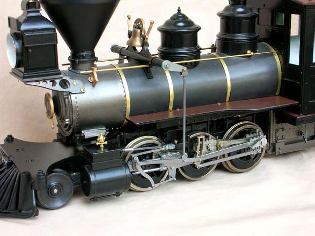
60

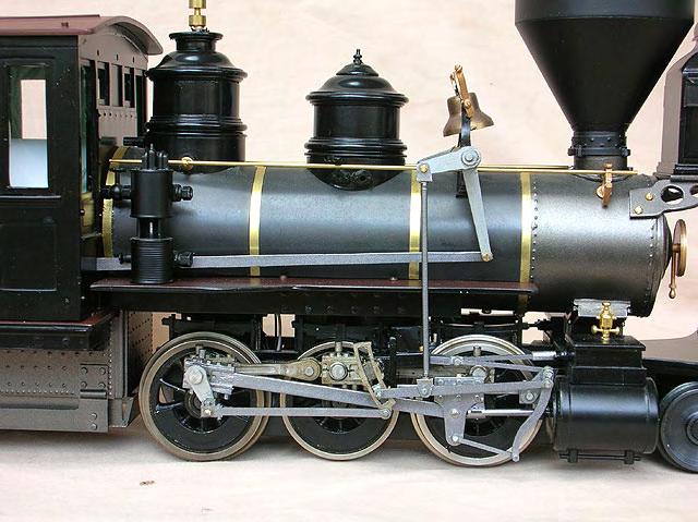
61 Loco in Forward Motion.
62 Loco set in Neutral. Loco set in Reverse Motion.
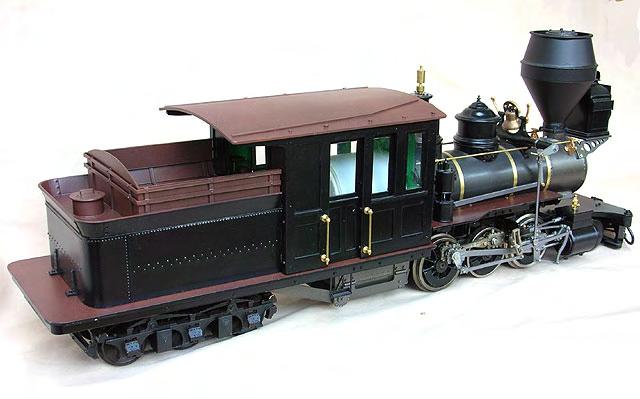
63

64 Good Luck! David Fletcher January Special Thanks: We extend our special thanks to the following people in bringing this chapter to you: Vance Bass - My Editor, and most important guy to us all in making all this legible- Proofreading, ideas and help throughout. Barry Olsen - BBT, chassis and parts. Jim Wilke - Ongoing assistance with historically correct colour schemes and locomotive details. Philip Jensen from Hartland Trains - for his assistance with parts and the DIY Mason frame concept. Chris Walas - For his ongoing support and seriously cool article on the articulated loco. Jens Lasch - Tender truck article and very fine model work. Tom Farin - Mason Bogie archive and prototype info. Rick Raively - For his continued efforts to bring us quality laser cutting in styrene. Shad Pulley - for the uploading of the chapter and for all the organising and distribution of the valve gear sets - no small task! Rich Schiffman and Jim Barron - for their ongoing support, ideas and production of Mason parts for all - and those downright stylish bell rigs!. Andy Bernat - for the solving of construction issues in building the laser cut chassis frame. and to all the supporters of this project and keeping the faith for such a long time.
PYRTE. Building The Front Axle, Fork and Steering
 PYRTE Building The Front Axle, Fork and Steering The front axle on this traction engine is a very simple affair, in that it is a rectangular steel rod, sat on edge, with a pivot in the centre, which is
Air Compressor/Water Pump III - Making the Steam Valves
 Page 1 of 14 Air Compressor/Water Pump Part III Making the Steam Valves Nelson Riedel Nelson@NelsonsLocomotive.com Initial: 1/09/04 Last Revised: 0 The cylinders pistons and water valves were completed
Bachmann GWR Earl (Dukedog) EM Finescale Conversion
 EM Finescale Conversion") Bachmann GWR Earl (Dukedog) EM Finescale Conversion Before you start, it is a good idea to have some small containers or snap top poly bags to put screws and components in for safe keeping...much better
Bachmann GWR Earl (Dukedog) EM Finescale Conversion Before you start, it is a good idea to have some small containers or snap top poly bags to put screws and components in for safe keeping...much better
Connecting the rear fog light on the A4 Jetta, while keeping the 5 Light Mod
 Connecting the rear fog light on the A4 Jetta, while keeping the 5 Light Mod DISCLAIMER: I'm human and make mistakes. If you spot one in this how to, tell me and I'll fix it This was done on my 99.5 Jetta.
*Some speedometers have these additional electronic connections. If yours does, then remove the smaller slotted screws shown.
 www.odometergears.com 1981-1985 240 Cable-Driven Speedometers (NOT for 1986 and later electronic units) http://www.davebarton.com/240-odometer-repair.html For this set of instructions below, I will not
Drawings 18, and 21 are each made of 3 parts. Stick them together to see the whole drawings for each of 18,19.20,21.
 Hi chaps, as Mason class CH7 PDFs are nearing completion, I'm ready to release the 1883 Westinghouse fitout drawings on the Mason Bogie. This has been one big effort to sort out, as the DSP&P brake system
Hornby Railroad Crosti 9F EM Finescale Conversion.
 Hornby Railroad Crosti 9F EM Finescale Conversion. Before you start, it is a good idea to have some small containers or snap top poly bags to put screws and components in for safe keeping...much better
Stephenson's Valve Gear: 7mm cast white-metal kit 19 th Century swing-link version - non-working, cosmetic only. Instructions
 SER-Kits Stephenson's Valve Gear: 7mm cast white-metal kit 19 th Century swing-link version - non-working, cosmetic only Page 1 of 5 Instructions HEALTH & SAFETY: The castings contain some lead. Dispose
upper and lower ball joints ( I went with Moog from rockauto.com): two K80026 and two K8607T
: two K80026 and two K8607T") Parts required: two 5C3Z*4A322*AA = hub / steering knuckle o-ring two AC3Z*1S175*A = updated axle shaft "dust seal" two 5C3Z*3254*A = steering knuckle / axle shaft seal upper and lower ball joints ( I
Parts required: two 5C3Z*4A322*AA = hub / steering knuckle o-ring two AC3Z*1S175*A = updated axle shaft "dust seal" two 5C3Z*3254*A = steering knuckle / axle shaft seal upper and lower ball joints ( I
Hornby Railroad Hall EM Finescale Conversion.
 Hornby Railroad Hall EM Finescale Conversion. The subject of this sheet is the new (2015) Hornby Railroad Hall. There are several specification and livery variants, but all have a common chassis and as
There is hence three things you can do - add oil, adjust the temp that the clutch begins to engage, or do both.
 As most of you may be aware, I have been doing a lot of research lately on our cooling system in the 80's including the fact that we have a dead spot on the OEM temp gauge which prompted me to not rely
Gearbox Assembly 101. Introduction. Before Beginning. By Mark Schutzer 4/13/06
 Gearbox Assembly 101 By Mark Schutzer 4/13/06 Introduction If you are planning to re-motor an old brass locomotive you may want to upgrade to a new gearbox at the same time. The early 60 s and 70 s gearboxes
Shay - Painting The Trucks & Frames
 Shay - Painting The Trucks & Frames Nelson Riedel Nelson@NelsonsLocomotive.com Initial:2/23/04 Last Revised: 06/06/2004 Painting of the locomotive trucks and frame are described in this page. The tender
Air Compressor/Water Pump IV - Pilot Valve Stem, Test & Installation
 Page 1 of 8 Air Compressor/Water Pump Part IV Pilot Valve Stem, Test & Installation Nelson Riedel Nelson@NelsonsLocomotive.com Initial: 1/13/04 Last Revised: 0 Valve Test: I decided to test the steam valves
M1A1 Thompson Upgrade
 M1A1 Thompson Upgrade If you are mechanically inclined at all. This should be no problem. I'll start off with a list of things you will need. Thompson M1A1 Whisky Cigarettes Tools: Flat screwdriver No.
CHAPTER 11: FLYWHEEL, CLUTCH AND ALTERNATOR BACK ON
 CHAPTER 11: FLYWHEEL, CLUTCH AND ALTERNATOR BACK ON Posted on the Wildguzzi forum by Pete Roper: January 17, 2006: Contents: Assembling the engine. Flywheel, clutch and alternator back on. Pic 11-1: To
Plumbing Part VI - Blowdown Valve Nelson Riedel Initial: 9/28/03 Last Revised: 04/24/2006
 Page 1 of 8 Plumbing Part VI - Blowdown Valve Nelson Riedel Nelson@NelsonsLocomotive.com Initial: 9/28/03 Last Revised: 0 When I started to think about the blowdown I realized that I'd never seen the actual
Conversion to Renault NG 5 speed gearbox with cable actuated gear change
 Europa Series 2 (1969) Conversion to Renault NG 5 speed gearbox with cable actuated gear change NB: this is theoretical it shifts very precisely without too much effort in the garage with no oil in the
This document goes through the basic steps required to utilize the electric window motors from the Ford Mk3 Mondeo.
 Modifying Ford Mk3 Mondeo door glass motors The options for installing electric windows in a Diablo replica are limited to only a few options; You can install the original motor and cable runners at 500
U-Score U-Score AAC Rank AAC Rank Vocabulary Vocabulary
 go 1 927 you 2 7600 i 3 4443 more 4 2160 help 5 659 it 6 9386 want 7 586 in 8 19004 that 9 10184 like 10 1810 what 11 2560 make 12 1264 is 13 10257 on 14 6674 out 15 2350 do 16 2102 here 17 655 eat 18
Instructions for Assembling Driving Wheels, Axles and Crankpins
 Instructions for Assembling Driving Wheels, Axles and Crankpins (Version 1; October 2008) Introduction These instructions explain how to assemble Exactoscale 4mm scale driving wheels, axles and crankpins
Heljan EM Finescale Conversion.
 Heljan 02 2-8-0 EM Finescale Conversion. Before you start, it is a good idea to have some small containers or snap top poly bags to put screws and components in for safe keeping...much better than crawling
INSTRUCTIONS FOR NYC K-11 PACIFIC KIT #100200
 INSTRUCTIONS FOR NYC K-11 PACIFIC 4-6-2 KIT #100200 These instructions provide photographs of completed model, exploded-view drawings, diagrams, step-by-step instructions and an itemized parts list. If
As stated, these are solely based off of how I like to do the Pre-Trip. I give my personal opinions as well as some helpful tips.
 Here are our sections: Engine Compartment Drivers Door Fuel Area Coupling System Trailer (Please note in the type of suspension your trailer has) Light Check In-Cab Inspection and Brake Tests You will
Inside a typical car engine. Almost all cars today use a reciprocating internal combustion engine because this engine is:
 Tech Torque HOW PETROL ENGINES WORK The Basics The purpose of a gasoline car engine is to convert gasoline into motion so that your car can move. Currently the easiest way to create motion from gasoline
Improving the gearshift feel in an SW20.
 Improving the gearshift feel in an SW20. Part one In 3 parts. The SW20 gearshift can be often be greatly improved by eliminating play in the shift linkages, and this article covers three areas that need
9 Locomotive Compensation
 Part 3 Section 9 Locomotive Compensation August 2008 9 Locomotive Compensation Introduction Traditionally, model locomotives have been built with a rigid chassis. Some builders looking for more realism
Timing the 9N/2N Steering Sector Gears
 Timing the 9N/2N Steering Sector Gears by John Korschot - www.johnsoldiron.com (May 2010) The procedure for timing a set of steering gears in the 9/2n tractors is published in the I&T FO4 shop manual.
Disco 3 Clock Spring / Rotary Coupler replacement
 Disco 3 Clock Spring / Rotary Coupler replacement I recently had to change my Clock spring and thought some folks may find it helpful to see what it entailed. I did lots of reading around but couldn t
The kit includes everything seen here, and there are only a few upgrades or mods available.
 The kit includes everything seen here, and there are only a few upgrades or mods available. Complete Kit $1,445.00 1 pair trailing arms LH/RH, with poly lined Monster balls. Pinion angle corrected 1 pair
4mm scale 009 gauge Lodge Hill & Upnor railway Chattenden Drewry loco body kit.
 RT Models 4mm scale 009 gauge Lodge Hill & Upnor railway Chattenden Drewry loco body kit. HISTORY The loco was supplied by the Drewry car co. to the Lodge Hill & Upnor Railway in 1949, works number 2263.
How to Set the Alignment on Ford Mustangs
 How to Set the Alignment on 1967-1973 Ford Mustangs Let's Get This Straight - Mustang Monthly Magazine Christopher Campbell Technical Editor March 25, 2015 Frontend alignment is one of the most basic adjustments
4TH GEN SEATS IN A 3RD GEN TRUCK
 4TH GEN SEATS IN A 3RD GEN TRUCK by Flopster843 02 Oct 2016 If you drive a 3rd generation Dodge Ram truck, I am sure you have discovered that the OEM seats are not the greatest (Figure 1.) They are extremely
Hard Bar Sport, M1/M2 Hard Core Hardtop, M2 Sport, and Xtreme Installation Instructions
 HARDWARE KIT: Hard Bar Sport, M1/M2 Hard Core Shoulder Harness Guide Relocation Assemblies: 2-3/8" X 1" grade 8 bolts 4-3/8" flat washers 2-3/8" lock nuts 2 - brass bushings 2 - plastic trim caps 2-3/8"
Our goal is to make the install a breeze. Please read the entire guide before beginning.
 www.airkewld.com Page 1 of 6 IRS Axle Kit Install IRS Axle Kit Install Our goal is to make the install a breeze. Please read the entire guide before beginning. KITS SHOULD INCLUDE 2 - Control-arm mounting
Fly Rocket Fly: Design Lab Report. The J Crispy and The Airbus A
 Fly Rocket Fly: Design Lab Report The J Crispy and The Airbus A380 800 Rockets: Test 1 Overall Question: How can you design a water, bottle rocket to make it fly a maximum distance. It needs to be made
Conversion of a Turnigy 9X to Hall effect sensors
 Conversion of a Turnigy 9X to Hall effect sensors Because English is not my mother language I kindly ask to be gracious. Unfortunately I had several times some problems with the low quality potentiometers
Bachmann Spectrum Peter Witt in HO
 Bachmann Spectrum Peter Witt in HO By Bob Dietrich This is my impression of an unpainted Peter Witt from Bachmann Spectrum. The packaging of the car was impressive a large red box with a clear cover showing
Brake master cylinder replacement
 Brake master cylinder replacement 8-25-2010 I had replaced the front brake master cylinder a few years ago when it developed a bad leak, at that time, I ordered a new master cylinder from Spartan, very
DC Series Installation Manual (# )
") DC Series Installation Manual (# 101630) Page 1 of 33 In this booklet you will find: TOWER INSTALLATION... 3 U-Bolt Style mount... 4 Side Frame Style mount... 4 PIVOT INSTALLATION... 5 External Pivot Installation:
DC Series Installation Manual (# 101630) Page 1 of 33 In this booklet you will find: TOWER INSTALLATION... 3 U-Bolt Style mount... 4 Side Frame Style mount... 4 PIVOT INSTALLATION... 5 External Pivot Installation:
Here's the difference (externally) in the and 04+ bumper and headlights: (00-03 on top, 04 on bottom)
 in the and 04+ bumper and headlights: (00-03 on top, 04 on bottom)") OK guys, I've been meaning to post this for awhile.. well here it goes. I did the '04 front end conversion on my '01 about 4-5 months ago, but then the dealer had to buy the car back for legal reasons.
OK guys, I've been meaning to post this for awhile.. well here it goes. I did the '04 front end conversion on my '01 about 4-5 months ago, but then the dealer had to buy the car back for legal reasons.
N-series Remote Port Modification
 N-series Remote Port Modification Introducing the Old Tractor Guy (totg) by Dan Allen (a.k.a. TheOldHokie) When I first acquired my 9N in the late 80's one of the first things I wanted to do with it was
 www.odometergears.com Mercedes-Benz Mechanical Odometer Repair This how to can be used for all mechanical repairs as the only difference will be the removal of the instrument cluster. http://www.dieselgiant.com/repairyourodometer.htm
How to Replace the Main Axle Gear on the Bachmann Spectrum GScale using the NWSL # upgrade gear.
 How to Replace the Main Axle Gear on the Bachmann Spectrum GScale 4-4-0 and 2-6-0 Mogul (2001era), using the NWSL #2223-6 upgrade gear. By Paul M. Newitt (all text and photos Copyright Paul M. Newitt,
There was some debate whether or not there was a write up, with Pictures, for replacing the ignition switch.
 Replacing the Ignition Switch - Step by Step with Pictures. http://forums.audiworld.com/showthread.php?p=18927576 (Corey 02ALMSTT) (With updates/corrections by Dave F.) February 1, 2013 (I = Corey, mostly)
Bachmann. Climax. Phoenix Sound Systems, Inc West Liberty Road Ann Arbor MI
 Bachmann Climax Phoenix Sound Systems, Inc. 3514 West Liberty Road Ann Arbor MI 48103 www.phoenixsound.com phone: 800-651-2444 fax: 734-662-0809 e-mail: phoenixsound@phoenixsound.com 2004-2007 Phoenix
what you need to do is hit the taper housing as hard as you can with your hammers AT THE SAME TIME and at a slight angle, what will happen is you
 first things first, get the car on axle stands and the wheels off. Open the bonnet to let more light through to the area in which you'll be working. The following guide shows the passenger side being done
Roehrig Engineering, Inc.
 Roehrig Engineering, Inc. Home Contact Us Roehrig News New Products Products Software Downloads Technical Info Forums What Is a Shock Dynamometer? by Paul Haney, Sept. 9, 2004 Racers are beginning to realize
Amateur Radio Station WFØGM Repairing a Yaesu G-1000DXA Rotor
 WFØGM Home http://wf0gm.fpage.com/index.htm Amateur Radio Station WFØGM Repairing a Yaesu G-1000DXA Rotor (Part 1 of 2) The following is my experience with a faulty Yaesu G-1000DXA Rotor, and how I repaired
Door Panel Removal & Window Stop Adjustment
 Door Panel Removal & Window Stop Adjustment By: Jeff Wolford Disclaimer: This is simply an article of how I fixed my car. I m not responsible if you break, scratch, or mess up anything following my example.
THE TORQUE GENERATOR OF WILLIAM F. SKINNER
 THE TORQUE GENERATOR OF WILLIAM F. SKINNER IN 1939, WHICH WAS THE START OF WORLD WAR TWO, WILLIAM SKINNER OF MIAMI IN FLORIDA DEMONSTRATED HIS FIFTH-GENERATION SYSTEM WHICH WAS POWERED BY SPINNING WEIGHTS.
The 2mm Scale Association etched replacement chassis for RTR loco bodies
 The 2mm Scale Association etched replacement chassis for RTR loco bodies Required Parts List Chassis etch (supplied) Motor - for all designs the Association can motor is suitable, alternatives are shown
Setup Guide and Chassis Tuning Tips (simple version) By Jim Daniels
 By Jim Daniels") This document is released into the public domain and may be reproduced and distributed in its entirety so long as all credit to Jim Daniels remains. If you find this guide helpful please consider donating
This document is released into the public domain and may be reproduced and distributed in its entirety so long as all credit to Jim Daniels remains. If you find this guide helpful please consider donating
Hornby GWR Star Class EM Finescale Conversion.
 Hornby GWR Star Class EM Finescale Conversion. Before you start, it is a good idea to have some small containers or snap top poly bags to put screws and components in for safe keeping...much better than
BBK Ceramic Long Tube Headers (99-04 Cobra and Mach 1) - Installation Instructions
 - Installation Instructions") BBK Ceramic Long Tube Headers (99-04 Cobra and 03-04 Mach 1) - Installation Instructions The below installation instructions work for the following products: BBK Ceramic Long Tube Headers (99-04 Cobra
BBK Ceramic Long Tube Headers (99-04 Cobra and 03-04 Mach 1) - Installation Instructions The below installation instructions work for the following products: BBK Ceramic Long Tube Headers (99-04 Cobra
1. Invert the tender, and hold in a suitable device. We use a foam cradle the Peco loco service cradle being ideal.
 Bachmann J11 EM Finescale Conversion Before you start, it is a good idea to have some small containers or snap top poly bags to put screws and components in for safe keeping...much better than crawling
Norden. A Lancashire Mill Engine. Scale: 1:12
 Scale: 1:12 Neil M. Wyatt February 2009 Fig. 1: General Arrangement General Arrangement Sheet: 1 An Old Steam Engine DEAR SIR, In the ruins of an old mill at, near Rochdale, there is an old steam engine
Lakela nd H2 Low Speed Stator Coil Installation
 Lakela nd H2 Low Speed Stator Coil Installation Step 1: Place the stator assembly on a padded surface to protect the plastic signal generators, and orient it as shown in figure 1. The low speed coil is
Jaguar Update. Adjustable Reaction Plate
 Jaguar Update Adjustable Reaction Plate Home January 7, 2008 I recently installed an adjustable reaction plate from CoolCat Express Corp. I've included some notes from that experience. I'm not affiliated
How to Change Front Brake Pads on a Toyota Corolla
 How to Change Front Brake Pads on a Toyota Corolla Link to this article on (All other links in this document are disabled) Follow this picture guide to change the front brake pads on a 2003-2008 Toyota
Ball Joint Replacement for 2005 F L SuperDuty SRW, 4x4 with ESOF
 Ball Joint Replacement for 2005 F-250 6.0L SuperDuty SRW, 4x4 with ESOF Parts required: two 5C3Z-4A322-AA = hub / steering knuckle o-ring (my originals were yellow, the replacements are black) two AC3Z-1S175-A
Installing LED lights in a Hypercharger By Keith Edwards Joker s Wild! (Wildjokr)
") Installing LED lights in a Hypercharger By Keith Edwards Joker s Wild! (Wildjokr) THINGS YOU WILL NEED: A Hypercharger (duh!) LEDs (The ones I got were from Benny Bryant at Fantasies on Wheels in Sylacauga,
Installing LED lights in a Hypercharger By Keith Edwards Joker s Wild! (Wildjokr) THINGS YOU WILL NEED: A Hypercharger (duh!) LEDs (The ones I got were from Benny Bryant at Fantasies on Wheels in Sylacauga,
The Magazine For Slot Car Enthusiasts
 The Magazine For Slot Car Enthusiasts Building the Tomy Super G+ By Milt Surratt Tomy Super G+ slot cars have been around in the current form for about 12 years. Out of the package, the Tomy HO slot car
Converting a Chevy Non-positraction rear-end to a positraction rear using an Eaton posi unit.
 Converting a 56-62 Chevy Non-positraction rear-end to a positraction rear using an Eaton posi unit. Tom Parsons Non-posi unit Posi unit 1 Converting a 56-62 Chevy Non-positraction rear-end to a positraction
Scratchbuilding an F25 Well Flat Car
 Scratchbuilding an F25 Well Flat Car By David J. Vinci (Flat Figure 1) Well flats are a pretty rare car type generally, but the Pennsy seems to have had the lion s share of variety. Most of these cars
$1.00 FOR THE TQIO/RCIO
 $1.00 FOR THE TQIO/RCIO m mm HDBBYSHOP Champion Jay Halsey has an impressive track record. One of Jay's advantages is a whisper smooth tranny thanks to his dad, Jim. Now you can build a Halsey transmission!
Днепр) Russian Motorcycle Carburetors Part 2B: PZ-24 and PZ-28 Carburetor Assembly and Jet Drilling
 Russian Motorcycle Carburetors Part 2B: PZ-24 and PZ-28 Carburetor Assembly and Jet Drilling") Ural (Урал( Урал) - Dnepr (Днепр( Днепр) Russian Motorcycle Carburetors Part 2B: PZ-24 and PZ-28 Carburetor Assembly and Jet Drilling (applies also to K-37 K and K-38 K carbs) Ernie Franke eafranke@tampabay.rr.com
Ural (Урал( Урал) - Dnepr (Днепр( Днепр) Russian Motorcycle Carburetors Part 2B: PZ-24 and PZ-28 Carburetor Assembly and Jet Drilling (applies also to K-37 K and K-38 K carbs) Ernie Franke eafranke@tampabay.rr.com
The distinguishing features of the ServoRam and its performance advantages
 ADVANCED MOTION TECHNOLOGIES INC 1 The distinguishing features of the ServoRam and its performance advantages What is a Linear Motor? There are many suppliers of electrical machines that produce a linear
Mikuni RS Carburetor Conversion
 Mikuni RS Carburetor Conversion After putting your carbies on the bench or the kitchen table if the wife is out, you will see that the linkages may be in different positions depending on which brand of
How to Build with the Mindstorm Kit
 How to Build with the Mindstorm Kit There are many resources available Constructopedias Example Robots YouTube Etc. The best way to learn, is to do Remember rule #1: don't be afraid to fail New Rule: don't
The Body Slinger
 http://www.scaryguys.com/slinger.htm The Body Slinger The body slinger is a nifty animation that looks like a benign corpse in a coffin until its triggered, then leaps almost straight up over your head!
2007 Crown Victoria Police Interceptor (P71) Blend Door Actuator Replacement (If I did it, you can too.)
 Blend Door Actuator Replacement (If I did it, you can too.)") 2007 Crown Victoria Police Interceptor (P71) Blend Door Actuator Replacement (If I did it, you can too.) I'm not saying this is the only way, or even the right way, but it worked for me. First time I've
2007 Crown Victoria Police Interceptor (P71) Blend Door Actuator Replacement (If I did it, you can too.) I'm not saying this is the only way, or even the right way, but it worked for me. First time I've
The drawings are all available from the author or from the host websight. You will find these pictures and descriptions to be most helpful.
 Last Revision: 10JA2010 1969 THRU 1976 GM A & F-CAR STANDARD (NON-ADJUSTABLE) STEERING COLUMN DISASSEMBLY & REPAIR INSTRUCTIONS PAPER #1 Disassembly and Repair Instructions Addressed in this Paper Degree
LAMBO VERTICAL DOOR HOW TO GUIDE
 -1 LAMBO VERTICAL DOOR HOW TO GUIDE Despite what you may believe, scissor doors are not that difficult to install. There are plenty of body shops out there that will charge you $2,000 - $10,000 for this
ALIGNING A 2007 CADILLAC CTS-V
 ALIGNING A 2007 CADILLAC CTS-V I ll describe a four-wheel alignment of a 2007 Cadillac CTS-V in this document using homemade alignment tools. I described the tools in a previous document. The alignment
We all put our heads together to try and determine what the facts were. They were as follows:
 VWvortex Forums > Eos > How to solve (or prevent) Eos Roof leaks As many of you know, I don t own an Eos. This makes it difficult to provide practical advice based on my own experience with the car, as
Lincoln Mark VII T5 Swap Version submitted by 5.0 bird
 Lincoln Mark VII 1984-1989 T5 Swap Version 20070611 submitted by 5.0 bird I've decided to make an article to assist with the T5 swap for the 84-89 Mark VIIs, since I was just in there because my DOA didn't
FITTING OIL TEMP AND PRESSURE GUAGES
 FITTING OIL TEMP AND PRESSURE GUAGES this guide is of reference to fitting an oil temp and pressure sender/ sensor into a sandwich plate- not the sump plug temp sensor (although it wouldn't be much different
Adjusting brake shoes for AutoPark parking brake
 Adjusting brake shoes for AutoPark parking brake This document is a compilation of several separate writeups. What we're trying to do here is consolidate the necessary information needed for you to make
Re-building a Caliper
 Re-building a Caliper by Leslie Henson The pistons in the calipers on the 90 are in very poor condition, and although the brakes work ok, it plays on our mind that the pistons are badly corroded, and it
Compact 6-Speed and Reverse Gearbox
 Compact 6-Speed and Reverse Gearbox By Alan Wenbourne Downloaded from the South East London Meccano Club Website www.selmec.org.uk The Gearbox During the construction of my demonstration Direct Shift Gearbox
How I Fitted the Digital Temperature Guage... By T-Cut
 How I Fitted the Digital Temperature Guage... By T-Cut Here's one way to install the digital temperature gauge designed by Hans Schaaper. I decided to fit mine into the redundant slot above the CD-80 radio
GM A-Body Instructions 3 & 2½ Header Applications w/ Balance Tube Crossover
 GM A-Body Instructions 3 & 2½ Header Applications w/ Balance Tube Crossover Included with this kit are the following: 2 Collector Reducers 1 Balance Tube Kit A 2 Headpipes 2 Tailpipes 2 Tailpipe Extensions
Bag 1. Bag 1. Center Pivot. Center Pivot
 8 00734 01901 5 Center Pivot Bag 1 3374 - Center Pivot Socket 4019 - Alum Pivot ball 3254-2-56 Button Head *Note - Sometimes it is helpful to slightly over-tighten the top clamp screws, then work the ball
RS-2 SINGLE ACTION REAR BUMPER WITH TIRE CARRIER INSTALL MANUAL FOR JEEP WRANGLER ALL MODELS.
 RS-2 SINGLE ACTION REAR BUMPER WITH TIRE CARRIER INSTALL MANUAL FOR 2007-2016 JEEP WRANGLER ALL MODELS. Rear Bumper Installation Instructions 1) Remove factory rear bumper, (this includes all tow hitch
Porsche 928 with 16v LH-Jetronic Fuel System
 Porsche 928 with 16v LH-Jetronic Fuel System Toll-Free Tech Hot Line: 877-FOR-928M 877-367-9286 Please do not copy this manual and give copies to your friends. Our ability to bring you this supercharger
structure table of contents: squarebot chassis parts and assembly 2.2 concepts to understand 2.27 subsystems interfaces 2.37
 The structural subsystem of the robot is responsible for physical support. It holds everything in place, and is, in effect, the durable skeleton of the robot to which all the other subsystems are attached.
How I installed new brake pads on my i with Sport Package (should be fine for other E39 s) By Robert B.
 By Robert B.") How I installed new brake pads on my 1999 528i with Sport Package (should be fine for other E39 s) How I installed new brake pads on my 1999 528i with Sport Package (should be fine for other E39 s) By
How I installed new brake pads on my 1999 528i with Sport Package (should be fine for other E39 s) How I installed new brake pads on my 1999 528i with Sport Package (should be fine for other E39 s) By
S1 Sequential. T56 Magnum. Sequential shifter. Contents and assembly instructions
 S1 Sequential Sequential shifter T56 Magnum Contents and assembly instructions Parts List Sequential shifter x1 Base plate x1 Base spacer x1 Drill Square x1 Shaft fitting x1 Square washer x1 8mm Aluminium
RAFIG IDLE TUNING PROCESS
 RAFIG IDLE TUNING PROCESS I decided to PDF this process and bring everything I found into one document as when I went to idle tune it was in bits and pieces so I have gathered SSpdmon s info and put it
10.1. THE RS PARTS SUMP GUARD
 10.1. THE RS PARTS SUMP GUARD A magnesium alloy sump guard was always standard wear for any selfrespecting Escort rally machine in the past, but supply problems and soaring costs resulted in RS Parts producing
1967 (Late) CORVETTE STANDARD (NON-ADJUSTABLE) STEERING COLUMN DISASSEMBLY & REPAIR INSTRUCTIONS PAPER #2
 CORVETTE STANDARD (NON-ADJUSTABLE) STEERING COLUMN DISASSEMBLY & REPAIR INSTRUCTIONS PAPER #2") Last Revision: 03SE2012 1967 (Late) - 1968 CORVETTE STANDARD (NON-ADJUSTABLE) STEERING COLUMN DISASSEMBLY & REPAIR INSTRUCTIONS PAPER #2 Disassembly and Repair Instructions Addressed in this Paper Degree
Last Revision: 03SE2012 1967 (Late) - 1968 CORVETTE STANDARD (NON-ADJUSTABLE) STEERING COLUMN DISASSEMBLY & REPAIR INSTRUCTIONS PAPER #2 Disassembly and Repair Instructions Addressed in this Paper Degree
Rekluse Motor Sports. The z-start Clutch. Husaberg
 Rekluse Motor Sports The z-start Clutch Husaberg Installation Guide Copyright 2002-2004 Rekluse Motor Sports z-start Revision 3.000 RMS126 Husaberg 04+ 191-226 Rekluse Motor Sports, inc. 110 E. 43 rd Street
This is what we are trying to create in the steps below
 You will need: (1) Some 3/4 aluminium or steel flat bar (+/- 1 foot) (2) About 12 of 3 Aluminium or steel tubing. (2) Piece of 3X3 silicone hose and 2 hose clamps (3) 1 K&N (or similar) high flow filter
Rear Speaker replacement.
 Rear Speaker replacement. First off you need the right rear speakers. The easy bit is 6x9 and better than a 15W paper cone, the difficult bit is getting a mounting depth under 74mm. Or to be more precise,
1964 1/2-70 Mustang Torque Arm Rear Suspension Installation Instructions
 1964 1/2-70 Mustang Torque Arm Rear Suspension Installation Instructions 1-800-984-6259 www.totalcostinvolved.com Version 2 (c) 2008 Total Cost Involved Engineering, Inc. All Rights Reserved. Page 1 of
Bachmann D11 EM/S4 Finescale Conversion
 Bachmann D11 EM/S4 Finescale Conversion Before you start, it is a good idea to have some small containers or snap top poly bags to put screws and components in for safe keeping...much better than crawling
Headlamp Adjusters motorised conversion by: Ant (Banjo1981)
") Headlamp Adjusters motorised conversion by: Ant (Banjo1981) What you will need: E30 adjuster switch assembly E30 Headlight adjusters E36 Adjuster motors (pref with the plugs still attached) Variable resistor
Headlamp Adjusters motorised conversion by: Ant (Banjo1981) What you will need: E30 adjuster switch assembly E30 Headlight adjusters E36 Adjuster motors (pref with the plugs still attached) Variable resistor
Should I Leave My Manual Car In Gear When Parked
 Should I Leave My Manual Car In Gear When Parked I just wanted to know who people leave there car in first gear while there car is It's definitely saved my car a few times since my parking brake cables
Aamir_bt The legend..
 Aamir_bt The legend.. How to do timing on a 4XE1-W (DOHC) engine. well i decided to to a write up for DOHC timing since there was only the SOHC written up, and i had to do a timing belt on my stylus anyways,