structure table of contents: squarebot chassis parts and assembly 2.2 concepts to understand 2.27 subsystems interfaces 2.37
|
|
|
- Samuel Smith
- 6 years ago
- Views:
Transcription


1 The structural subsystem of the robot is responsible for physical support. It holds everything in place, and is, in effect, the durable skeleton of the robot to which all the other subsystems are attached. structure
2 structure table of contents: squarebot chassis parts and assembly 2.2 concepts to understand 2.27 subsystems interfaces 2.37 structure subsystem inventory
3 squarebot chassis parts and assembly The Structure and Motion subsystems are very tightly integrated to form the chassis of the Squarebot. The chassis assembly instructions refer to components from both the Structure and Motion sections. Follow the steps in this section to build the chassis. 1 Collect and identify the parts from the list of materials below: materials qty structure subsystem bearing flat 12 panel 1 chassis rail 4 chassis bumper 2 partially threaded beams, 2" 4 keps nut hex screw, ¼" hex screw, ½" 20 motor " removable tire " detachable hub 4 36-tooth gear 4 60-tooth gear 2 collar w/ threaded set screw 10 square bar, 2" 2 square bar, 3" hex screw, ½" 4 motion subsystem 2 2


4 chassis rail x 4 chassis bumper x 2 2" partially threaded beam x hex screw, ¼" x 26 keps nut x hex screw, ½" x hex screw, ½" x 4 2 3


5 panel x 1 motor x " removable tire x " detachable hub x 4 2 4

6 36 tooth gear x 4 collar w/threaded set screw x 10 square bar, 2" x 2.5" square bar, 3" x 4 60 tooth gear x 2 bearing flat x
7 2 Inner chassis rails You will need two chassis rails, one for the right side and one for the left side. Orient them as shown, so that the narrow face is pointing up and the open sides are facing each other. x 2 Add four bearing flats to the chassis rails (two per rail, on the outward-facing sides). Be sure to position the bearing flats such that the central hole of each bearing flat is aligned with the fourth hole from the respective end of the chassis rail, as shown. x 4 2 6

8 2 Inner chassis rails, continued Secure the bearing flats to the chassis rails using two ½" 8-32 screws and two keps nuts per bearing flat, as shown. ½" x 8 x 8 Your completed inner chassis rails should look like this when you re done: 2 7


9 2 Outer chassis rails Position two more chassis rails as shown, just as you did for the inner chassis rails. x 2 Connect two 2" partially threaded beams to each of the rails, using a ¼" 8-32 screw for each beam. Position the rear beam on the fourth square hole from the back end of the chassis rail, and the front beam on the fifth square hole from the front end of the chassis rail. 2" ¼" x 4 x4 2 8

10 2 Outer chassis rails, continued Add bearing flats to the inner faces of the two chassis rails. The center hole of the bearing flat should be aligned with the eighth hole from the front end of the chassis rail, in the middle row of holes. x 2 Secure each bearing flat with two ½" 8-32 screws and two keps nuts. ½" x 4 x 4 2 9

11 2 Outer chassis rails, continued Your outer chassis rails should now look like this: Now add two bearing flats to the outer surface of each chassis rail, so the center hole of each bearing flat is over the fourth hole from the respective end of the chassis rail, as shown. These are the same positions as the bearing flats you put on the inner chassis rails earlier. x
12 2 Outer chassis rails, continued Again, secure the bearing flats to the chassis rails using two two ½" 8-32 screws and two keps nuts per bearing flat. ½" x 8 x 8 Your outer chassis rails should now look like this: 2 11


13 3 Motor Subassembly Before starting on the motor subassembly, make sure that the clutch is installed in the motor, as shown. x 2 Insert a 2" square beam into each clutch, making sure that they seat firmly. The square bar will act as the motor s drive shaft. 2" x


14 3 Motor Subassembly, continued Slide the pre-assembled inner chassis rails onto the square bar motor shafts, so that the shafts go through the middle hole in the middle row of each rail. Install one bearing flat on the outward-facing side of each chassis rail, with the front hole of the bearing flat sliding onto the motor shaft as shown. x

15 3 Motor Subassembly, continued Your assembly should now look like this: Secure the bearing flat to the inner chassis rail and motor using two ½" 6-32 screws per motor. Note that these are the thinner screws, not the usual 8-32 ones. ½" x 4 Your assembly should now look like this: 2 14
16 3 Chassis Subassembly Insert a 3" square bar through the center hole of each unoccupied bearing flat, as shown. Don t push them all the way through. Push the end of the bar about ¹/8" through the rail. 3 3" x


17 4 Chassis Subassembly, continued Slide metal collars (with threaded screws) onto each of the 2" and 3" square bars, mounting them flush with the surface of the bearing flat against which they will sit. Be sure the square bars don t get pushed too far in while you put the collars on, or you will not have enough bar sticking out to mount the wheels later. x 6 Once the collars and bars are in position, tighten the threaded screws with the smaller 5/64" hex L wrench to keep the collars from sliding out of place. 2 16
18 4 Chassis Subassembly, continued Slide a 60-tooth gear onto the drive axle of each motor, pushing it flush against the collar that you added in the previous step. 60-tooth x

19 4 Chassis Subassembly, continued Slide a 36-tooth gear onto each of the remaining square bars, pushing them flush against the collars. 36-tooth x


20 4 Chassis Subassembly, continued Add another collar to the end of each 3" square bar, again pushing them flush against the face of the gear before tightening the screws. x 4 Tighten the threaded screws with a 35/64" hex L wrench. 2 19

21 4 Chassis Subassembly, continued Install the pre-assembled outer chassis rails onto the current assembly. All three of the square bars sticking out of the inner rail should go neatly through bearing flats on the outer rail. Note: If you find that your gears are sliding on the axles, you can insert the 0.182" and 0.318" plastic spacers included in the kit to block them into place. 2 20

22 4 Chassis Subassembly, continued Place chassis bumpers on the front and rear of the chassis rails, as shown. x


23 4 Chassis Subassembly, continued Secure the vertical faces of the chassis bumpers to the end of the chassis rails using four ¼" 8-32 screws and keps nuts in the front, and four in the back. ¼" x 8 x


24 4 Chassis Subassembly, continued Secure the horizontal faces of the chassis bumpers to the top of the chassis rails using ¼" 8-32 screws and keps nuts, six in the front and four in the back. These holes remain open to allow other subsystems to use them as attachment points. ¼" x 10 x


25 4 Deck Subassembly Place the large flat panel on the 2" partially threaded beams, aligning each corner of the panel with one of the threaded beams. x


26 4 Deck Subassembly Secure the panel to the threaded beams with four ¼" 8-32 screws, as shown. ¼" x


 on the 3\"")

27 4 Deck Subassembly Install the small green tires (2.75" Removable Tire and 1.895" Hub) on the 3" square beams, as shown. x 2 Your Squarebot chassis is complete! 2 26
28 concepts to understand Stability: Center of Gravity Considerations Center of Gravity You can think of the robot s center of gravity as the average position of all the weight on the robot. Because it is an average of both weight and position, heavier objects count more than lighter ones in determining where the center of gravity is, and pieces that are farther out count more than pieces that are near the middle. Support Polygon The support polygon is the imaginary polygon formed by connecting the points where your robot touches the ground (usually the wheels). It varies by design, but there is always one support polygon in any stable configuration. Stability The rule for making a robot stable is very simple: the robot will be most stable when the center of gravity is centered over the polygon. Your robot will encounter much more complex situations than just standing still, however, and you need to take these into account when making your design. 2 27
29 concepts to understand, continued Stability: Center of Gravity Considerations, continued EXAMPLE 1: Towerbot This robot was built very tall so that it would be able to reach a hanging goal for a challenge. However, along the way, it had to first climb a ramp. Notice that the robot s center of gravity is no longer over the support polygon. This robot would fall over as soon as it started up the ramp. 2 28
30 concepts to understand, continued Stability: Center of Gravity Considerations, continued EXAMPLE 1: Towerbot, continued To fix this problem, you must lower the robot s center of gravity so that it does not move as far when the robot is on an incline. In general, it is always advantageous to have your robot s center of gravity as close to the ground as possible! Center of Gravity is Still Over Support Polygon 2 29
31 concepts to understand, continued Stability: Center of Gravity Considerations, continued EXAMPLE 2: Grabberbot This robot is designed to pick up a heavy object using the gripper claw on the front, and transport the object to another location. When the robot picks up the object, it effectively adds it to the robot s structure. The combined robot-ball structure now has the new center of gravity (shown below), which is outside the support polygon. The robot tips over as a consequence. Center of Gravity is Directly Over Support Polygon (but not by much) Heavy Weight Near Front of Robot Moves Center of Gravity Far Forward Center of Gravity is No Longer Over Support Polygon 2 30
32 concepts to understand, continued Stability: Center of Gravity Considerations, continued EXAMPLE 2: Grabberbot, continued There are many solutions to this problem. Depending on the specifics of the challenge, some or all of these modifications could work: Moving the center of gravity back by moving the gripper farther back on the robot Weight Still Pulls Center of Gravity Forward, but Not as Far as Before Center of Gravity Remains Over Support Polygon Extending the support polygon by adding more wheels farther out Moving the center of gravity back by adding counterweights on the back of the robot Additional Weight Pulls Center of Gravity Back Toward Center Center of Gravity is Over Newly Extended Support Polygon Center of Gravity Remains Over Support Polygon 2 31
33 concepts to understand, continued Sturdiness Fasteners There are over a hundred screws in your starter kit. Use them! The most common problems with robots that fall apart or lose pieces easily is not that individual parts come apart or bend, but rather that groups of parts are not joined securely enough, and separate from each other or move around. Single Screw EXAMPLE 1: Arm Extension A robot needs to be able to reach a goal that is high off the ground. The goal is so high that a single long piece will not reach it. Two pieces must be joined together to reach the desired height. Arm Rotates Too Easily Around This Point 2 32
34 concepts to understand, continued Sturdiness, continued EXAMPLE 1, continued: Arm Extension, continued This attachment uses a single screw to join the two bars. As you can see, it has a problem when weight is applied to it: the extension bar rotates around the screw. Also, if this screw were to come loose or fall out for any reason, the entire arm would come crashing down. Two Screws Eliminate Rotation By using two screws, this design removes the possibility of rotation around either one of them. Additionally, the design is much more resilient, and can maintain its shape to a limited extent even if one of the two screws were to come loose or fall out. 2 33
35 concepts to understand, continued Sturdiness, continued EXAMPLE 2: Bracing The extended bars are now attached firmly to each other, and the long arm is mounted on your robot. However, the long arm is liable to generate huge stresses at its mounting point because it is so long, especially when the force is applied near the end. In order to keep the arm from falling back down, you will need to brace it. You could use a second screw to hold it, like you did with the arm itself, but because the arm has so much mechanical advantage from its length (it is effectively a lever), that screw would actually be in danger of deforming or breaking. A better solution would be to give the structure support at a point closer to the end, thus reducing the mechanical advantage that the arm has relative to the supports. Single Screw Mounting Point Long Lever Arm Causes Great Strain on Mounting Point Large Stress on Weak Mounting Point Causes Structural Failure 2 34
36 concepts to understand, continued Sturdiness, continued EXAMPLE 2: Bracing the Bars, continued The arm is now more stable and better able to withstand stresses placed on it from both its own weight, and any external forces acting on it. It has both decreased the mechanical advantage from the long lever arm, and spread the load over two supports instead of just one. Bracing Arm Provides Support And Shortens Lever Arm Shorter Lever Arm Causes Less Strain On Mounting Screw There are Now Two Supports 2 35
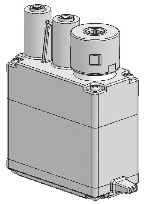
37 concepts to understand, continued Exposure and Vulnerability There are certain parts of a robot that are more fragile than others. Always plan the structural design to protect these parts from unwanted physical contact if possible. The design in the example at the right is asking for trouble. The Vex Micro Controller is a sensitive piece of electronic equipment, and it can be a poor design decision to put it somewhere like this where it could be damaged by a simple physical impact. In particular, this design leaves the back of the Vex Micro Controller exposed in such a way that a passing robot or a careless driver could smash the entire rear connector panel, potentially damaging the radio control and power connections. Also, the wires are a mess. This is dangerous, because if one of those wires were to snag on another robot (or even on the robot s own wheels!), the connector would be forcibly removed from its port. Not only would this disable the robot on the field, but it could cause permanent damage to the cable or the ports on the Vex Micro Controller. Adjusting the position of the controller so that it is not likely to get hit by anything, and cleaning up the wires (the kit comes with wire ties) reduce the chance of damage to the sensitive electronic components on the robot. As a bonus, it looks a lot cleaner as well. 2 36
38 subsystem interactions How does the Structure Subsystem interact with the Motion Subsystem? The motion and structure subsystems are tightly integrated in many robots designs, including the Squarebot. The motion subsystem can t be constructed without certain structural components (like the chassis rails) to provide support and positional reference. By the same token, the structure subsystem must be designed largely to accommodate the motion components. On Squarebot, the structure and motion subsystems are so interconnected that you cannot build them separately. Hence, they are constructed together in the Squarebot chassis assembly instructions. the Power Subsystem? The structure subsystem generally provides a safe, protected place to secure the battery. On the Squarebot, the structure subsystem provides a mounting platform for the battery holder, on the upper deck of the chassis (see Power Subsystem building instructions). the Sensor Subsystem? The structure subsystem provides a mounting and stabilization platform for sensors on the robot. Often, sensors need to be held in a specific position to function properly, and the structural subsystem must be designed to accommodate these needs. On the Squarebot, the structure subsystem provides a mounting spot for the bumper switch sensors, where they can detect collisions from the front and rear. the Control Subsystem? The structure subsystem will generally provide a place to store the RF Receiver module on the robot. In some cases, you will need to construct a piece to hold the antenna wire in a safe place, or to hold it up above the robot to extend its signal range. On Squarebot, the structure subsystem provides an elevated deck for the RF receiver module and antenna holder to be mounted for enhanced reception. the Logic Subsystem? The structure subsystem holds the Micro Controller in place. Since the Micro Controller is a very delicate and important part of the robot, the structure subsystem will also need to provide physical protection for the Micro Controller by keeping it in a secure spot. The structure subsystem does not plug into the Micro Controller in any way; however, the structure subsystem does need to provide accommodation and protection for the wires that run between the Micro Controller and other pieces. On the Squarebot, the structure subsystem provides a mounting platform for the Micro Controller module, and a place to tie wires down. 2 37


")
")
39 structure subsystem inventory component qty component qty chassis bumper 2 long bar 4 chassis rail 4 long angle bar 4 panel 2 fully threaded 10 beams (½") fully threaded 8 beams (1") 2 38

 washer,")
 washer, delrin 10")
 14 plus gusset 2 screw")

40 structure subsystem inventory, continued component qty component qty partially threaded 4 beams (2") washer, steel 30 partially threaded 4 beams (3") washer, delrin 10 keps nut (¼") 65 pivot 2 lock nut (¼") 14 plus gusset 2 screw 8-32 x ¼" 70 screw 8-32 x ³/8" 28 gusset 2 screw 8-32 x ½" 28 screw 8-32 x ¾"


41 structure subsystem inventory component qty bearing block 6 bearing flat " plastic 20 spacer 0.318" plastic 20 spacer collar 16 threaded screw 16 for collar lock plate


42 structure accessories metal and hardware kit screw, 8-32 x ¼" x 70 chassis rail x 4 plate x 2 screw, 8-32 x 3/8" x 28 chassis bumper x 2 screw, 8-32 x ½" x 28 lock nut x 14 screw, 8-32 x ¾" x 14 collar x 16 threaded screw for collar x 16 plus gusset x " plastic spacer x 20 bearing block x 6 washer, steel x 30 bearing flat x 16 washer, delrin x " plastic spacer x 20 keps nut x 65 insert 2005 Innovation One. All Rights Reserved. INSERT THESE PAGES at the back of the Structure Chapter in your Vex. accessories Metal and Hardware: This kit contains additional structural elements that you can use to build bigger, better, stronger, and more complex robot designs. Or, since bigger isn t always better use the pieces in this kit to make sure that you always have the most efficient part for the job. All the parts included in this kit were also included in the Starter Kit, so consult your original for building tips and examples on how to use them. metal and hardware kit 1 Vex and Vex Robotics Design System are trademarks of Innovation One.
 x 4 partially threaded beam (3\") x 4 square bar")
 x 8 Limited 90-day Warranty This product is")
 days from the date of purchase from authorized Innovation One")

43 structure accessories metal and hardware kit, continued fully threaded beam (½") x 10 long angle bar x 4 partially threaded beam (2") x 4 partially threaded beam (3") x 4 square bar (2") x 4 long bar x 4 square bar (12") x 2 pivot x 2 square bar (3") x 4 gusset x 2 lock plate x 4 accessories fully threaded beam (1") x 8 Limited 90-day Warranty This product is warranted by Innovation One against manufacturing defects in material and workmanship under normal use for ninety (90) days from the date of purchase from authorized Innovation One dealers. For complete warranty details and exclusions, check with your dealer. Innovation One, Inc. 350 North Henderson Street Fort Worth, TX /04 Printed in China 0105 metal and hardware kit 2 insert
motion table of contents: squarebot assembly 3.2 concepts to understand 3.3 subsystems interfaces 3.21 motion subsystem inventory 3.
 The subsystem of the robot is responsible for exactly that,. It includes both the motors that generate, and the wheels and gears that transfer and transform that into the desired forms. With the structural
Squarebot Upgrade (2.0 to 3.0) Conversion Instructions (cont.)
 Conversion Instructions (cont.)") Squarebot Upgrade (2.0 to 3.0) Conversion Instructions 1 Collect and identify the parts from the list of materials below: materials qty Squarebot 2.0 1 8-32 hex screw x 1/4 16 8-32 hex screw x 1/2 10 6-32
Squarebot Upgrade (2.0 to 3.0) Conversion Instructions 1 Collect and identify the parts from the list of materials below: materials qty Squarebot 2.0 1 8-32 hex screw x 1/4 16 8-32 hex screw x 1/2 10 6-32
Teachers Resource: BaseBot Assembly
 Teachers Resource: BaseBot Assembly Overview: This document contains all the instructions for assembling the BaseBot. The diagram numbers correspond to the section of the REC curriculum in which the instructions
Working with VEX Parts
 VEX Robotics Design System VEX Classroom Lab Kit The VEX Robotics Design System is divided up into several different Subsystems: Structure Subsystem Motion Subsystem Power Subsystem Sensor Subsystem Logic
Motion. Table of Contents: Introduction to the Motion Subsystem 3.2. Concepts to Understand 3.8. Subsystem Interactions Motion.
 The Motion Subsystem of the robot is responsible for exactly that, motion. It includes both the motors that generate motion, and the wheels and gears that transfer and transform that motion into the desired
Manipulators. Example 1: The Claw
 Manipulators With these examples we will demonstrate some basic designs to accomplish each of the game piece challenges involved in the 2018 FIRST Global game Energy Impact to: 1. Collect fuel cubes and
Base Kit Chain Drivetrain Build Guide
 222fg Base Kit Chain Drivetrain Build Guide August 11, 2017 Chain Drivetrain Build Guide Copyright 2017 REV Robotics, LLC 1 1.1 Description This document outlines the steps required to four wheel, chain
RHINO SUSPENSION SYSTEM INSTALLATION INSTRUCTIONS
 PARTS INCLUDED: 2 FRONT UPPER A-ARMS 2 FRONT LOWER A-ARMS 2 UNI-BALL JOINTS 2 UNI-BALL JOINT STUDS 2 UNI-BALL JOINT CAPS 2 RETAINING RINGS 1 FRONT SHOCK ASSEM. 2 DELRON STEERING STOPS 2 SHOCK MOUNT SPACERS
A robot is a programmable mechanical device that can perform tasks and interact with its environment, without the aid of human interaction
 Welcome to... T H E A robot is a programmable mechanical device that can perform tasks and interact with its environment, without the aid of human interaction 1. How to Plan The Design Process Create
Prusa i3 Printer Assembly Guide
 Prusa i3 Printer Assembly Guide Special thanks to Carlos Sanchez and Miguel Sanchez for the graphics. All graphics captured from their great animation: http://www.carlos-sanchez.com/ Prusa3/ For copyright
INSTALLATION INSTRUCTIONS QA1 P/N x400, x500, x600, x400, x500, x F100 Front Coil-over Suspension System
 INSTALLATION INSTRUCTIONS QA1 P/N 52620-x400, 52620-x500, 52620-x600, 52621-x400, 52621-x500, 52621-x600 65-72 F100 Front Coil-over Suspension System TOOLS AND SUPPLIES REQUIRED Floor Jack Two (2) Jack
GM G-BODY LSD INSTALLATION
 GM G-BODY 1979-1987 LSD INSTALLATION INSTALLATION INTRODUCTION 1. REMOVING THE FENDER AND DOORS FROM THE A-PILLAR AND DISCONNECTING THE WIRE HARNESS @ THE DOOR JAM 2. REMOVING THE EXISTING DOOR HINGES
GPS AutoSteer System Installation Manual
 GPS AutoSteer System Installation Manual Supported Vehicles Agco Gleaner Combines R65 R66 R75 R76 PN: 602-0288-01-A LEGAL DISCLAIMER Note: Read and follow ALL instructions in this manual carefully before
RED RAVEN, THE LINKED-BOGIE PROTOTYPE. Ara Mekhtarian, Joseph Horvath, C.T. Lin. Department of Mechanical Engineering,
 RED RAVEN, THE LINKED-BOGIE PROTOTYPE Ara Mekhtarian, Joseph Horvath, C.T. Lin Department of Mechanical Engineering, California State University, Northridge California, USA Abstract RedRAVEN is a pioneered
Assembly Instructions for the CNCTRK AZ/EL Positioning Unit
 Assembly Instructions for the CNCTRK AZ/EL Positioning Unit Introduction/Overiview The AZ/EL Unit consists of two stages of identical gearboxes joined together with a configuration adapter. Note that this
2103 NITRO RAIL DRAGSTER KIT
 203 NITRO RAIL DRAGSTER KIT THANKS FOR BUYING RJ SPEED S NITRO DRAG KIT. IT IS A LITEWEIGHT CAR MADE FOR STRAIGHT LINE DRAG RACING AND CAN BE BROKEN IF RUN INTO SOLID OBJECTS AT HIGH SPEED. YOU WILL NEED
Robot Construction, Wiring, and Safety
 Robot Construction, Wiring, and Safety SSI Robotics September 7, 2013 Capitol College Basic construction Build it strong Build it stable Build it to last Protect sensitive parts Gearing Make motors do
Joy Rider Shock System Installation
 Joy Rider Shock System Installation Manufacturer s Part Numbers: 3 Inch Single Axle 200103 UPC 784672350945 2⅜ Inch Single Axle 200102 UPC 784672350921 Each single axle kit contains the following: 2 Shock
CNCTRK AZ/EL Positioning Unit Assembly Instructions. Rev
 CNCTRK AZ/EL Positioning Unit Assembly Instructions Rev4 016-01-05 Introduction/Overiview The AZ/EL Positioner Unit, RAZEL, consists of two stages of identical gearboxes joined together with a Configuration
PRO COMP SUSPENSION PART# F-150 ADD-A-LEAF KIT. Suspension Systems that Work!
 2360 Boswell Road Chula Vista, CA 91914 Phone 619.216.1444 Fax 619.216.1474 E-Mail tech@explorerprocomp.com PRO COMP SUSPENSION Suspension Systems that Work! PART# 13134 2004 F-150 ADD-A-LEAF KIT This
VEX IQ Curriculum: Let s Get Started
 VEX IQ Curriculum: Let s Get Started Let s Get Started Student Handout Using VEX IQ Hardware The VEX IQ platform kits provide easy, fun, and accessible tools to teach and learn all four legs of STEM, no
CHEVROLET TAHOE/DENALI/AVALANCHE/YUKON/ SILVERADO/SIERRA 2007+
 CHEVROLET TAHOE/DENALI/AVALANCHE/YUKON/ SILVERADO/SIERRA 2007+ INSTALLATION INTRODUCTION 1. REMOVING THE FENDER AND DOORS FROM THE A-PILLAR AND DISCONNECTING THE WIRE HARNESS @ THE DOOR JAM 2. REMOVING
Chevy Chevy 2500 & 3500 SuperRail Mounting Kit #3515
 1999-2007 Chevy 1500 1999-2010 Chevy 2500 & 3500 SuperRail Mounting Kit #3515 #3600 SuperGlide (24K) Gross Trailer Weight (Maximum) Vertical Load Weight (Max. Pin Weight) 24,000 lbs. 6,000 lbs. Installation
Fast Master Products, Inc. P.O. Box 654, Katy Texas Tel: (281) Fax: (281)
 Fax: (281)") Fast Master Products, Inc. P.O. Box 654, Katy Texas 77492-0654 Tel: (281) 391-6750 Fax: (281) 391-6760 Email: info@cruiserlift.com Easy installation and removal from the pick-up bed. Compatible with all
Fast Master Products, Inc. P.O. Box 654, Katy Texas 77492-0654 Tel: (281) 391-6750 Fax: (281) 391-6760 Email: info@cruiserlift.com Easy installation and removal from the pick-up bed. Compatible with all
Assembly Manual. 1/10th Formula 1 Car
 Assembly Manual 1/10th Formula 1 Car Center Pivot Bag 1 3374 - Center Pivot Socket 40194 - Hard Anodized Alum Pivot ball 3254-2-56 *Note - Sometimes it is helpful to slightly over-tighten the top clamp
STOP. Broadcast Spreader. Operator's Manual. Model No Safety Assembly Operation Maintenance Parts
 Operator's Manual STOP Broadcast Spreader Model No. 486.2400 DO NOT RETURN TO STORE For Missing Parts or Assembly Questions Call 1-866-56-8388 CAUTION: Before using this product, read this manual and follow
FORD SuperRail Mounting Kit #3361
 FORD SuperRail Mounting Kit #3361 #4100 SuperGlide (16K) #4400 SuperGlide (20K) Gross Trailer Weight (Maximum) Vertical Load Weight (Max. Pin Weight) 16,000 lbs. 4,000 lbs. Gross Trailer Weight (Maximum)
Bonds Hoists. Remote Control Operated Ceiling Lamp Lifter. National and International Patents Apply. Instruction for Installation and Operation
 Bonds Hoists Remote Control Operated Ceiling Lamp Lifter National and International Patents Apply Instruction for Installation and Operation 0044 (0)845 365 1 007 info@bondshoists.com www.bondshoists.com
Mustang. MOD1 Coilover Kit FXXADK0100, FXXADK0200, FXXADK0400 FXXA1K0100, FXXA1K0200, FXXA1K0400
 1964.5-1973 Mustang MOD1 Coilover Kit FXXADK0100, FXXADK0200, FXXADK0400 FXXA1K0100, FXXA1K0200, FXXA1K0400 2276 Research Dr. Livermore, Ca 94550 Ph: (925)-443-6300 E: maier@mikemaierinc.com Page 1 of
Replacing MK4 Golf/Jetta radiator mounts in-car
 Replacing MK4 Golf/Jetta radiator mounts in-car This is a guide to replacing the radiator mounts in a MK4 Golf/Jetta. This involves moving the core support to the service position which allows you to do
/ YOUR TOW VEHICLE AND EQUIPMENT
 5 / YOUR TOW VEHICLE AND EQUIPMENT There are some other important things you should know about towing your trailer. Towing a trailer will subject you to new and different challenges on the highway than
RoughDeck TM FXB Flexure Base Floor Scale. Installation/Operation Manual
 RoughDeck TM FXB Flexure Base Floor Scale Installation/Operation Manual SM 32958 13 Contents 1. Introduction... 1 1.1 Scale Components... 1 1.2 Operating Requirements... 2 1.3 How Flexure Levers Work...
Lifting Mechanisms. Example 1: Two Stage Lift
 Lifting Mechanisms The primary scoring method for the 2018 game is to deposit fuel cubes into scoring zones. A manipulator fixed to your robot can deliver fuel cubes into ground level scoring zones, but
The H-MAC Heavy Metal Articulating Chassis Construction Guide
 The H-MAC Heavy Metal Articulating Chassis Construction Guide The Heavy Metal Chassis is constructed with two identical drive modules built using 10 mechanical sub-assemblies. The drive modules are integrated
SERVICE MANUAL. Chairman. Playman/Robo
 SERVICE MANUAL Chairman Playman/Robo US How to contact Permobil Permobil Inc. USA 6961 Eastgate Blvd. Lebanon, TN 37090 USA Phone: 800-736-0925 Fax: 800-231-3256 Email: info@permobilusa.com Head Office
2101 NITRO PRO STOCK DRAG KIT 2104 NITRO PRO MOD DRAG KIT
 2101 NITRO PRO STOCK DRAG KIT 2104 NITRO PRO MOD DRAG KIT THANKS FOR BUYING RJ SPEED S NITRO DRAG KIT. IT IS A LITEWEIGHT CAR MADE FOR STRAIGHT LINE DRAG RACING AND CAN BE BROKEN IF RUN INTO SOLID OBJECTS
Wheel Angle Sensor Kit Installation
 Wheel Angle Sensor Kit Installation Item Component Part Number Qty 1. WAS Bracket Kit 200-0247-02 1 2. WAS Assembly Kit 200-0468-01 1 3. Instruction Guide 602-0401-01 1 602-0401-01-A Overview Always shut
AEV30308AA Last Updated: 05/31/18. 4 DUALSPORT sc SUSPENSION system for RAM 1500 air ride standard and rebel INSTALLATION GUIDE
 AEV30308AA Last Updated: 05/31/18 4 DUALSPORT sc SUSPENSION system for RAM 1500 air ride standard and rebel INSTALLATION GUIDE PLEASE READ BEFORE YOU START TO GUARANTEE A QUALITY INSTALLATION, WE RECOMMEND
OnBoard Drum Major Podium
 Assembly and Owner s Manual OnBoard Drum Major Podium CONTENTS CONTENTS................................................................................. 1 SAFETY...................................................................................
Marlon Xplore SxS Deck Owner s Manual Assembly & Installation Instructions
 Marlon Xplore SxS Deck Owner s Manual Assembly & Installation Instructions 2850lbs load max on deck 2500lbs load max on ramps Marlon Recreational Products www.marlonproducts.com 1-800-663-7367 IMPORTANT
Part # GM F Body Complete CoilOver System
 350 S. St. Charles St. Jasper, In. 47546 Ph. 812.482.2932 Fax 812.634.6632 www.ridetech.com Part # 11170109 70-81 GM F Body Complete CoilOver System Front Components: 1 11173509 Front Fixed Valving CoilOvers
INSTALLATION INSTRUCTIONS SEMI-HIDDEN WINCH MOUNT Part Number:70005 Application: Ford Super Duty
 INSTALLATION INSTRUCTIONS SEMI-HIDDEN WINCH MOUNT Part Number:70005 Application: Ford Super Duty Your safety, and the safety of others, is very important. To help you make informed decisions about safety,
CLAWBOT WITH SENSORS BUILDING INSTRUCTIONS
 CLAWBOT WITH SENSORS BUILDING INSTRUCTIONS USING THE VEX CORTEX Clawbot 1.0 1 1 Collect the parts and tools from the list below to attach the sensors: Materials Quantity Shaft, 4 Long 1 Shaft, 5 Long 2
INSTRUCTION MANUAL 16K - Fifth Wheel Hitch
 You can take it with you. INSTRUCTION MANUAL 16K - Fifth Wheel Hitch Product No. 30047 DEALER/INSTALLER: END USER: (1) Provide this Manual to end user. (2) Physically demonstrate hitching and unhitching
Contents. Section 5: Adjustments Ball Detect Adjustment Transport Band Tension Adjustment
 Contents Section 5: Adjustments... 5-3 1. Ball Detect Adjustment... 5-3 2. Transport Band Tension Adjustment... 5-5 3. Transport Band Drive Belt Tension Adjustment... 5-7 4. Ball Cushion Adjustment...
INSTALLATION INSTRUCTIONS SEMI Hidden Kit Part Number: Application: Toyota Tacoma
 INSTALLATION INSTRUCTIONS SEMI Hidden Kit Part Number: 100044 Application: 2016+ Toyota Tacoma GENERAL SAFETY PRECAUTIONS Your safety, and the safety of others, is very important. To help you make informed
Autodesk VEX Robotics Curriculum
 Page 1 of 22 Autodesk VEX Robotics Curriculum Activity In this activity, you build a complete robot called Tumbler. You start by building the right-side drive train. 1. To complete the first step: Locate
Nemesis-TCS Traction Control System Installation manual Honda CBR600 RR 2003_04 with race seat
 Nemesis-TCS Traction Control System Installation manual Honda CBR600 RR 2003_04 with race seat Kit part No. TCS-4C_CBR600_RR_0304.AA This application is designed for use with the Honda CBR600 RR 2003_2004
GPS AutoSteer System Installation Manual
 GPS AutoSteer System Installation Manual John Deere MFWD AutoTrac Ready Supported Models 8225R 8245R 8270R 8295R 8320R 8345R PN: 602-0254-01-A LEGAL DISCLAIMER Note: Read and follow ALL instructions in
COLD AIR INTAKE INSTALLATION INSTRUCTIONS
 COLD AIR INTAKE INSTALLATION INSTRUCTIONS # D760-0030 Fits: 2007-10 135i (E82, E88; with N54 engine) 2007-08 335i/xi (E90) 2007-10 335i (E92, E93; with N54 engine) Congratulations for being selective enough
Installation Instructions
 Equipment Required: Fastener Kit: F Wrenches: 15/16, 15/16 Crowfoot Adaptor Drill Bits: 1/4 Other Tools: Drill, Reciprocating saw Optional, Raise Bed: 18mm socket, 15 extension As an option you can loosen
JK HD Skid Plate for Rear Falcon Shocks
 1 JK HD Skid Plate for Rear Falcon Shocks Kit # 36-07-01-300 Important Notes: Prior to beginning this or any installation read these instructions to familiarize yourself with the required steps and evaluate
Bag 1. Bag 1. Center Pivot. Center Pivot
 8 00734 01901 5 Center Pivot Bag 1 3374 - Center Pivot Socket 4019 - Alum Pivot ball 3254-2-56 Button Head *Note - Sometimes it is helpful to slightly over-tighten the top clamp screws, then work the ball
INSTALLATION INSTRUCTIONS DODGE DAKOTA 2 KIT # 682 (2WD), 692 (4WD) 3 KIT # 683 (2WD), 693 (4WD)
, 692 (4WD) 3 KIT # 683 (2WD), 693 (4WD)") INSTALLATION INSTRUCTIONS 1997-1999 DODGE DAKOTA 2 KIT # 682 (2WD), 692 (4WD) 3 KIT # 683 (2WD), 693 (4WD) Installation of a Performance Accessories body lift kit will change the vehicle s center of gravity
INSTALLATION INSTRUCTIONS 1997-1999 DODGE DAKOTA 2 KIT # 682 (2WD), 692 (4WD) 3 KIT # 683 (2WD), 693 (4WD) Installation of a Performance Accessories body lift kit will change the vehicle s center of gravity
SuperQuest Salem Arms Best Practices
 SuperQuest Salem Arms Best Practices VEX Arm Designs Single 4-Bar 6-Bar 8-Bar Linear Slide Scissor Double Reverse 4-Bar Single Arms Arms These manipulators consist of a pivot point and at least 1 motor.
LSC 3052 PCW LANDSCAPE CART ASSEMBLY INSTRUCTIONS
 VESTIL MANUFACTURING CORP. 2999 North Wayne Street, P.O. Box 507, Angola, IN 46703 Telephone: (260) 665 7586 or Toll Free (800) 348 0868 Fax: (260) 665 339 www.vestilmfg.com e mail: sales@vestil.com LSC
Installation manual Toyota Tundra 4WD & 2WD - 2 front leveling kit Toyota Sequoia 4WD & 2WD - 2 front leveling kit Part # 52070
 Part # 52070 2007-2016 Toyota Tundra 4WD & 2WD 2008-2011 Toyota Sequoia 4WD & 2WD 2 front leveling kit Part # Description Qty. 52070-01 Front strut spacers 2 52070NB Hardware bag 1 52070INST Instruction
Between the Road and the Load Calculate True Capacity Before Buying Your Next Trailer 50 Tons in the Making
 Between the Road and the Load Calculate True Capacity Before Buying Your Next Trailer By Troy Geisler, Vice President of Sales & Marketing, Talbert Manufacturing Long before a single load is booked or
JK HD Skid Plate for Rear Falcon Shocks
 1 JK HD Skid Plate for Rear Falcon Shocks Kit # 36-07-01-300 Tools needed: Important Notes: Prior to beginning this or any installation read these instructions to familiarize yourself with the required
Adjustable Angled Incline Conveyor Owners Manual with Operating Instructions
 Adjustable Angled Incline Conveyor Owners Manual with Operating Instructions Revision 012211 Table of Contents Basic Conveyor Features 3 Getting Started 4 Setting Up the Incline Conveyor 5 Belt Removal
DUAL REMOTE OIL FILTER MODIFICATION 4 TH GENERATION FIREBIRDS
 Written by Dave Dorey (lonetechie) Copyright FirebirdNation.com The following article details how I installed a dual remote oil filter system on my 2001 Formula Firebird. If you decide to tackle this project,
LPE C5 Battery Relocation Kit
 LPE C5 Battery Relocation Kit The LPE C5 Corvette battery relocation kit improves vehicle weight distribution by moving weight to the rear of the vehicle. The improved weight distribution increases traction
Sport Sway Bar Kit C-10 Truck
 Sport Sway Bar Kit 22390 67-72 C-10 Truck Thank you for your purchase from our new line of Chevy parts. Please call us at 877-4NO - ROLL if you have any questions regarding the service or installation
SHIFNOID WIRING DIAGRAM
 SHIFNOID WIRING DIAGRAM FOR a HURST QUARTER STICK with a SN5055H THREE SPEED SOLENOID KIT IF YOUR RPM SWITCH OR TIMER SUPPLIES "NORMALLY OPEN GROUND" (SHIFNOID OR MSD) USE THIS DIAGRAM 86 NOT USED 87a
Dodge SuperRail Mounting Kit #3516
 1995-2002 Dodge SuperRail Mounting Kit #3516 #3600 SuperGlide (24K) Gross Trailer Weight (Maximum) Vertical Load Weight (Max. Pin Weight) 24,000 lbs. 6,000 lbs. Installation Instructions SPECIFICATIONS
RYOBI 10 in. TABLE SAW MODEL NUMBER RTS10G REPAIR SHEET
 RYOBI 10 in. TABLE SAW MODEL NUMBER RTS10G REPAIR SHEET 1 1 6 1 6 0 9 9 6 0 6 1 0 9 9 0 6 0 1 1 1 1 16 10 11 1 1 19 1 0 See Figure E 9 See Figure D See Note Page 11 9 FIGURE A 60 9 1 1 60 61 6 1 6 6 6
Owner s Manual Read and keep this manual. Patents World Wide
 Owner s Manual Read and keep this manual. Patents World Wide S & S Industries, Inc., Sarasota, FL, USA www.trail-gator.com Copyright 2006 All Rights Reserved The following manual is provided to assist
ACE 325/570 2 Lift Kit
 ACE 325/570 2 Lift Kit Polaris Ace 325/570 2014+ Part #: 5101244 Rev. 082316 491 W. Garfield Ave., Coldwater, MI 49036. Phone: 517-278-7768 E-mail: sales-rtpro@sporttruckusainc.com SAFETY WARNING RT Pro
ROBOTICS BUILDING BLOCKS
 ROBOTICS BUILDING BLOCKS 2 CURRICULUM MAP Page Title...Section Estimated Time (minutes) Robotics Building Blocks 0 2 Imaginations Coming Alive 5...Robots - Changing the World 5...Amazing Feat 5...Activity
RS-2 SINGLE ACTION REAR BUMPER WITH TIRE CARRIER INSTALL MANUAL FOR JEEP WRANGLER ALL MODELS.
 RS-2 SINGLE ACTION REAR BUMPER WITH TIRE CARRIER INSTALL MANUAL FOR 2007-2016 JEEP WRANGLER ALL MODELS. Rear Bumper Installation Instructions 1) Remove factory rear bumper, (this includes all tow hitch
Detroit Speed, Inc. Electric Headlight Door Kit Corvette P/N: &
 Detroit Speed, Inc. Electric Headlight Door Kit 1968-82 Corvette P/N: 122006 & 122007 The Detroit Speed Inc. Electric Headlight Door Kit replaces the stock vacuum actuated system on all 1968-82 Corvettes.
SIM RIG GT. Product Manual
 SIM RIG GT Product Manual Introduction Thank you for purchasing the Heusinkveld Engineering Sim Rig GT! This is a compact, clean, adjustable and very stiff simulator frame for a GT-style simracing experience.
Warnings and Precautions FAILURE TO READ, UNDERSTAND AND FOLLOW THESE INSTRUCTIONS MAY LEAD TO SERIOUS INJURY OR DEATH!
 Instruction Booklet 2006 Summit ATV Pak-Mule Single Axle 84000 Summit ATV Pak-Mule Tandem Axle 84002!! READ ME FIRST!!! Please read carefully BEFORE using you new Summit ATV Product. Congratulations! You
RF6 / RF10 / RF18 Installation Instructions
 RF6 / RF10 / RF18 Installation Instructions Thank you very much for purchasing PIAA product. Read this instruction manual thoroughly for proper use of the product. After completing your installation, please
CONTROL SYSTEM FOR THE PHYSICALLY DISABLED
 INSTALLATION Push/Rock HAND CONTROL SYSTEM FOR THE PHYSICALLY DISABLED With Howell Ventures Ltd Sure Grip Hand Control Systems and Accessories are warranted against manufacturing or material defects for
Instruction Manual 15K - Fifth Wheel Hitch Part Number 6030 & 6031
 DEALER/INSTALLER: (1) Provide this Manual to end user. (2) Physically demonstrate hitching and unhitching procedures in this Manual to end user. (3) Have end user demonstrate that he/she understands procedures.
INSTRUCTIONS FOR STRUT FRONT, 4-LINK REAR, 1 5/8 FRAME, FULL SIZE, 4130 ELIMINATOR CHASSIS
 #917230 Page 1 of 6 7230 INSTRUCTIONS FOR STRUT FRONT, 4-LINK REAR, 1 5/8 FRAME, FULL SIZE, 4130 ELIMINATOR CHASSIS ITEM QTY SIZE/PART NO. TUBE CODE DESCRIPTION 1 2 4350 Cage Side 2 2 4351 Forward strut
CHOOSING THE RIGHT TRAILER FOR YOUR NEEDS A Guide to Making the Right Choice
 CHOOSING THE RIGHT TRAILER FOR YOUR NEEDS A Guide to Making the Right Choice TRAILERS ARE A BIG INVESTMENT They empower your other investments and help with your toughest jobs. Nothing is more important
Automotive Storage Rack
 Automotive Storage Rack SPECIALIZED STORAGE For some years now, Rousseau has been developing a system that offers a complete and integrated storage solution for the automotive industry. Whatever your needs,
INSTALLATION MANUAL. AutoSteer Install Kit: AutoTrac Ready Installation
 INSTALLATION MANUAL AutoSteer Install Kit: 186-0002-01 186-0002-02 186-0002-03 186-0002-04 Please refer to this manual prior to beginning the installation of the AutoSteer system AutoTrac Ready Installation
Important Notes Note Recommended Equipment NOT included in kit
 Important Notes This helicopter is recommended for skilled intermediates and advanced RC helicopter flyers. Make sure to read and follow all the instructions in this manual, including all accessories.
Instruction Manual 30K - Fifth Wheel Hitch Part Number 30054
 You can take it with you. ELKHART, IN., OAKVILLE, ONT. Instruction Manual 30K - Fifth Wheel Hitch Part Number 30054 DEALER/INSTALLER: (1) Provide this Manual to end user. (2) Physically demonstrate hitching
Installation Instructions
 85-3180 rev. 07 03-14 Installation Instructions Thank you for purchasing this antisway bar kit. Please read through these instructions before installation. Front Anti-Sway Bar Kit for the Ford E350/450
EZ Carrier 3. Owner s Manual. Keep instructions for future reference
 EZ Carrier vv Owner s Manual Keep instructions for future reference Introduction The EZ Carrier provides all the flexibility you may need to transport your mobility scooter. The features include: The capability
ATV TRACK KIT. Operator s Manual Installation Instructions Service Instructions Replacement Parts List. Effective Date: October, 2012
 p/n 2258-642 ATV TRACK KIT Operator s Manual Installation Instructions Service Instructions Replacement Parts List Track Assembly Kits (p/n 1436-204) Mounting Assembly Kits (p/n 1436-205) 1436-815) Effective
The distinguishing features of the ServoRam and its performance advantages
 ADVANCED MOTION TECHNOLOGIES INC 1 The distinguishing features of the ServoRam and its performance advantages What is a Linear Motor? There are many suppliers of electrical machines that produce a linear
RJS WB ELECTRIC T/F DRAGSTER KIT LESS ELECTRICS
 RJS2006 30 WB ELECTRIC T/F DRAGSTER KIT LESS ELECTRICS THANKS FOR BUYING THIS RJ SPEED DRAGSTER KIT. IT IS MADE FOR STRAIGHT LINE DRAG RACING AND MAY BE BROKEN IF RUN INTO SOLID OBJECTS REPEATEDLY AT HIGH
BASIC VEHICLE CONTROL CHAPTER 3
 BASIC VEHICLE CONTROL CHAPTER 3 SECTION 1- INSTRUMENTS, CONTROLS, AND DEVICES WHEN YOU ARE READY TO BEGIN YOUR DRIVING EXPERIENCE, YOU MUST KNOW WHAT THE WARNING LIGHTS AND GAUGES ON THE PANEL TELL YOU.
SHERMAN UPGRADES SHERMAN SCREW KIT
 SHERMAN UPGRADES TANK NOT INCLUDED. SHOWN FOR REFERENCE ONLY. SHERMAN SCREW KIT Above is the Sherman Suspension Screw Kit. Socket head screws allow easier installation and removal, and also enhance the
Installation Instructions
 Equipment Required: Installation Instructions Fastener Kit: F Wrenches: 15/16, 10 mm Drill Bits: 1/4 Other Tools: Drill, Reciprocating Saw 9464/9474 HIDE-A-GOOSE HITCH All Fasteners Typical, Both Sides
AmTryke Adult Recumbent Model HP1000 #50-HC-1000
 AmTryke Adult Recumbent Model HP1000 #50-HC-1000 TOOLS Needed for Assembly 5 mm Allen Wrench 8 mm Socket or Wrench 10 mm Socket or Wrench 14 mm Socket or Wrench 15 mm Socket or Wrench 22 mm Socket or Adjustable
Build your own THUNDERBIRD 2
 PACK 03 PAGE 12 Pod 3 front hatch and Elevator Car 2 43 13 Pod 3 rear hatch and Elevator Car 2 46 14 Pod 3 floor and Elevator Car 2 49 15 Pod 3 frames and FAB 1 52 16 Pod 3 frames and FAB 1 55 17 Pod 3
INSTALLATION MANUAL 4 I.F.S. SUSPENSION CURR. CHEVY SUBURBAN / YUKON XL (WITH 5 LINK REAR END) PART # 14965
 PART # 14965") PART NUMBER : 14965 2000 CURR. SUBURBAN W/ REAR COIL SPRINGS 4 SUSPENSION SYSTEM WITH FRONT SPINDLES PARTS LIST: Part # Description Qty. C4I1SN-07 Passenger Side Differential Drop 1 C4I1SN-23 Driver Side
PART NUMBER : 14965 2000 CURR. SUBURBAN W/ REAR COIL SPRINGS 4 SUSPENSION SYSTEM WITH FRONT SPINDLES PARTS LIST: Part # Description Qty. C4I1SN-07 Passenger Side Differential Drop 1 C4I1SN-23 Driver Side
2014 GM 1500 TRUCK STOP---READ THIS FIRST! 7" Lift KIT. **Read These Entire Instructions Before Starting Anything**
 STOP---READ THIS FIRST! **Read These Entire Instructions Before Starting Anything** 2014 GM 1500 TRUCK LIFT KIT INSTRUCTIONS (PART #50768 & #50769 ) 5680 W. Barstow, Fresno, CA 93722 PH: (559) 226-8196
Valley. Center Pivots. reliable. durable. precise. advanced. responsive
 Valley Center Pivots reliable durable precise advanced responsive Durable Valley Structures Designed for Long Life When making decisions that affect your yields and bottom line, look to Valmont Irrigation
Installation Instructions. Fog Lights. The lamps get very hot when they have been in use. Do not touch them as they may cause burns.
 2100X Installation Instructions Thank you very much for purchasing PIAA product. Please read this entire manual before installation and use of this product. Fog Lights For Installers Please give this Installation
Performance You Can Count On FLEX-WING ROTARY CUTTERS
 Performance You Can Count On FLEX-WING ROTARY CUTTERS 1812 1815 2215 2810 2815 3810 3815 4815 2820 1812 FLEX-WING ROTARY CUTTER The 1812 Flex-Wing Rotary Cutter is designed for small tractors with a PTO
RZR 900 spring/shock installation
 RZR 900 spring/shock installation Thank you for purchasing the Shock Therapy Dual Rate Spring Kit for your RZR 900. Your item list: 2 Front upper coil springs, 2 Front lower coil springs, 2 Rear upper
INSTALLATION INSTRUCTIONS
 270 INSTALLATION INSTRUCTIONS 5-6 ! IMPORTANT PLEASE DON T HURT YOURSELF, YOUR KIT OR YOUR VEHICLE. TAKE A MINUTE TO READ THIS IMPORTANT INFORMATION. This kit is to be used on a pickup truck only, and
Installation Instructions PowerBoard Automatic Retracting Running Board
 Installation Instructions PowerBoard Automatic Retracting Running Board Vehicle Application Ford F150 Super Crew Cab 2009 Current : 75141-15 www.bestop.com - We re here to help! Visit our web site and