Setup Guide and Chassis Tuning Tips (simple version) By Jim Daniels
|
|
|
- Betty Norman
- 5 years ago
- Views:
Transcription
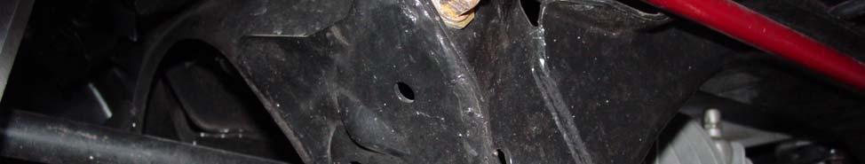
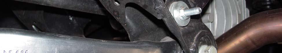
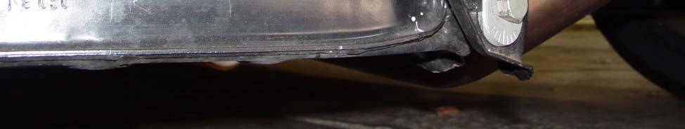
1 This document is released into the public domain and may be reproduced and distributed in its entirety so long as all credit to Jim Daniels remains. If you find this guide helpful please consider donating a small fee via the links located at Setup Guide and Chassis Tuning Tips (simple version) By Jim Daniels As promised the following is a walk through of how I setup my SM with a list of tuning tips I use at the track. Many have theories, thoughts and ingrained ideas on setup and tuning. I m not trying to change any of that, I m simply providing you with what I use on this type of racecar. I hope that you use this guide as a source to further your racing program and setup abilities. I welcome any suggestions you have, send them to me at jim@jimdaniels.com. This guide will be placed in the FAQ section of the web site. Expect 6-8 hours the first time you do this yourself, sometimes longer depending on your mechanical ability. This time estimate is AFTER you level your floor. Tools and equipment needed to do setup at home: Level surface (absolutely level, use shims to achieve if needed) Scales, camber gauge, toe plates, string Normal tools and jack stands Maybe some 8 sections of clear tube needed to level the workspace Before you start, a few things need to be done to the car, a few assumptions have to be made and a couple techniques explained. 1. The sway bars need to be disconnected on one side (I like the left side). 2. You need to find the center of the steering rack then lock down the column with a pair of vice grips and a bungee cord. This would be a good time to adjust the steering wheel adapter if it is off center from the rack s center. I use my steering wheel like a degree wheel to find the center. Then, I removed the hub and adjust the splines until the T on my steering wheel is square. 3. The tires need to be at hot pressures, 40 will do. 4. The driver s weight needs to be in the car at all times, I prefer a real person to sit there the whole time. If not, try to divide up body weight for torso, legs etc 5. Do yourself a favor and make sure the suspension bolts, perch adjusters and other hardware you will be adjusting are free, ready to adjust but not loose. 6. In the rear sub-fame, driver s side, just above the inboard lower bushing mounts you will see some holes cut by the factory. These holes are on both sides of the sub-frame again just up from those lower bushings. Find the two holes that are in alignment, one for the front of the sub-frame and one for the rear. Install a 3-4 bolt, the size of the hole, with a jam nut holding it in place. Have the bolts extent outward (front to the front and rear to the rear). These bolts establish the 1
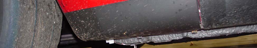
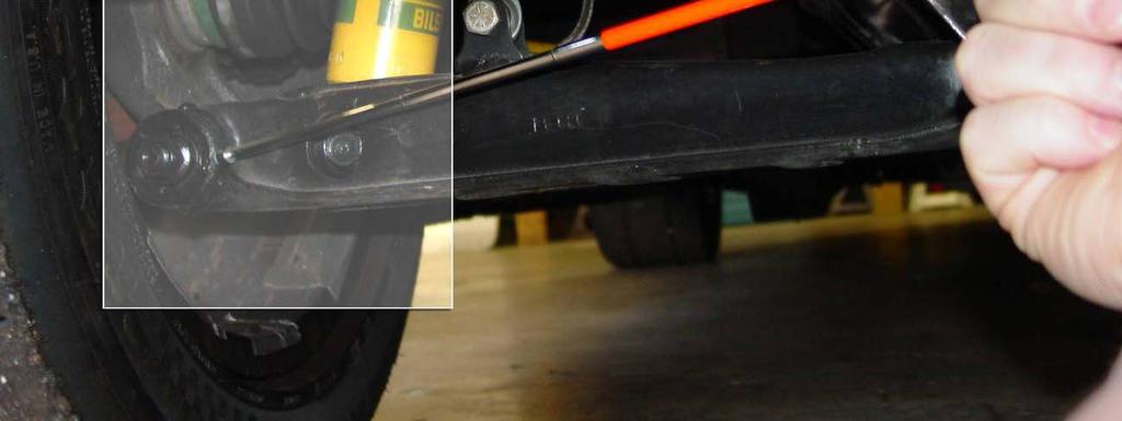
2 centerline of the car and will be used to square the car up in later steps (see Picture 1). 7. I make the assumption that no parts are bent and you have used your thumb to get toe and camber where it looks ok. 2 of toe out or +3 camber on one wheel is what I mean, correct that NOW by eye, do not spend too much time on it. 8. After each setting adjustment, bounce the car in place STOP, roll it 8-10 back then forward to where it was. NEVER, bounce again after you start rolling forward and always end your bounce going up, not down on the car. 9. You have a factory manual and know how to use it for finding out the procedures needed to make the setup adjustments. 10. Empty all fuel and put one gallon back in. 11. Using a fish scale, and after all prep is done, I measure the car s resistance on a flat surface. Record what it takes to just roll the car. Later, as you do maintenance, compare the freshly prepared car to the after raced car. If you gain resistance, look to see if there is a reason for that gain (brakes, fluid break down, bearings etc ). Correct if you can keeping in mind that you might establish a new resistance number after the car has seen the track and become seated in. Regarding setup and especially for new builds this process below will not be very fun as you will chase yourself narrowing the gap of the different settings. You will find out that when you make a change to one setting, others may be altered. Be patient, the gap will lesson until it is right. It Begins Step #1 (Ride Height) Using the spring perches, adjust the ride height to 5-1\4 at the pinch weld on the bottom of the car at the rocker panel (see Picture 2 & 3). It is normal for the LR to have more threads showing on the bottom compensating for the driver s weight. This will take sometime as you get used to how the car moves on one corner while you adjust another. BE PATIENT, keep going back and forth till it is near perfect. Remember this step, you will be back here again many times. You will not be showing the same amount of threads corner to corner. Remember, the floor where your car sits AND where you measure from needs to be level!!! Step #2 (LR Toe and Camber) We now need to square the car up so we can run through the first of several settings adjustments. Remember those bolts I had you install, now is the time to use them. They are used to measure the lower control arm on the driver s side rear wheel verse the centerline of the car. Using a telescopic measuring device, adjust the lower cam bolts until the distance between the bolts you installed, front and rear, and the back of the outboard bushing flange of the lower control arm are the same, front and rear (see picture 4). You now have zero toe on that wheel and that wheel is pointing straight. 2
3 While doing this wheel, go ahead and make the camber -2. You are adjusting the cam bolts anyway, this is what I like to do. Often, I do not have to touch this wheel again. JUST REMEMBER, if you get out of whack, set this wheel again and go from there, keep reading. Keeping this wheel square is vital to this process!! Step #3 (LF Toe, Camber and Caster) Time to get that kite string and jack stands out. Adjust 2 stands where they are slightly above the center wheel hub height. Tie your string securely to the portion of the stands that is adjustable. Now make final corrections so the string is level with the center line of the wheel hubs and tight enough to not be drooping. Ok, the Miata is wider in the rear, this is a pain. You should now have a string tied to the stands with it level with the hubs centerline with the stands stretched out about 3 past the front and rear wheels string tight. Basically, you will see a string running along the side of your car connected to the stands. Move the stands around until you have a 1 gap on the LR between the string and the wheel lip front and rear of that wheel. Once this is done, you have aligned the string to the wheel that you already aligned to the chassis, coming together for you now? As you set toe and make other adjustments, you will have to continue to square up the string to the LR wheel. BUT, after we get further along, we will drop the string and use toe plates, stay with me. Move to the front left wheel, measure from the string to the wheel lip, front and rear of the wheel, and inline with the string. Since the rack is centered and locked down and you have that 1 gap on the rear, you are looking at how far the toe is off verse the centerline of the car. Adjust toe on the LF to zero. Of course, you will have to resquare your string each time you roll the car. While doing this corner, you are going to set your camber to -2, your caster to +3-5 (just make sure the other side matches on caster later). Once the toe is zero, and the other settings are correct, secure this corner but do not tighten all the way just yet. Step #4 (RR Toe and Camber) We now are going to move to the passenger side of the car. Dust off them toe plates, their up now. Start by using your toe plates to get the RR to zero toe. While there, you guessed it, set the camber to -2. Once you are done, move to the RF corner. Remember, tighten to keep form moving only, no need to gorilla it at this point. Step #5 (LF Toe, Camber and Caster) Use the toe plates to match the left side, just like you did in the rear. Set the caster and camber to match the left front. At this point, the car is aligned with the centerline of the car, our ride height is set and our settings are in basic form. I call this the pre-scale setup. Good for you, these cars are not that corky, meaning not much chasing compared to other types of race cars. 3
4 Step #6 (Scaling) I assume you have been on the scales this whole time, the extra height helps for all the floor work you needed to do. Some even setup their scales to coincide with a lift, that s great as long as you check everything to make sure it is square. First, let s record the total weight of the car. Add/subtract ballast now. Once it is where you are comfortable we can move on to the scaling. We will only be dealing with percentages not the actual weight numbers. We will never get the corners to even out AND have a level platform for the suspension. So, we change balance with percentages on this car. Percentage to total weight is a common feature on most scales (as everyone else in racing uses them too). This is what I will be referring to from here on out. Record the Cross (always defined as the left rear and right front to total) weight % Record the left to right % Record the front to rear % Trade offs have to be made so we will concentrate on Wedge (cross weight) while maintaining ride height. NOTE: If a car has 49% of CW (cross weight) it is considered de-wedged. If it has 51% CW it is considered wedged. De-wedge helps the car turn left while tightening up the balance on rights. Vise versa with 51% wedge. I ll explain it more later. The fun begins! You are either REAL lucky and have a 50% car, it happens, or you see a car that is wedged or de-wedged. Based on your CW %, you need to make adjustments to the spring perches. The following procedure is crucial, a must. Keeping the ride height the same is your friend on track and in doing this setup. Forget what your brain tells you, just do what I say for this part. If you are de-wedged (less that 50%) you need to do the following. Up on the LR & RF Down on the RR & LF Make the adjustments in equal turns up and down (from whole turns to quarter turns). This will increase the CW with hardly any ride height change. One round is about 1.2%, your car may differ. Get it exactly 50%, not 50.1 or 49.9, 50.00%. If you are wedged (more than 50%) you need to do the following. Up on the RR & LF Down on the LR & RF 4
5 Make the adjustments in equal turns up and down (from whole turns to quarter turns). This will decrease the CW with hardly any ride height change. One round is about 1.2%, your car may differ. Get it exactly 50%, not 50.1 or 49.9, 50.00%. Step #5 (the recheck) GO BACK OVER ALL SETTINGS! If anything is out, repeat all the above steps, something has changed. Keep going through the steps until your step #5 yields the numbers we are after with no adjustments needed. It might take a few times or you might be blessed with the racing gods and get it right the first time. Once it is right, it should also be TIGHT!!!!!! Make sure you measure LAST, not tighten last. Step #6 (completion) Once you are finished either because it is right or because you just gave up, we have more things to do. First, set the sway bars to full stiff up front and full soft in the rear, NO PRELOAD!! Then, remove the vise grips from the column and let the guy that has been sitting in the car this whole time get out or remove the weight you used to simulate your body weight. The car will not look right, with no driver the platform is not level, and that s GOOD. We now have the car sitting there with zero toe all four, -2 camber all four, +3-5 caster both fronts (but the same side to side), 50% CW AND sitting with driver at 5-1/4 pinch weld to ground. Next, I will tell you what I do at the track to tune this beast! BUT, I ve won many competitive races with this very setup and all but the last 3-6 tenths is capable with the settings above. Enjoy, hope it helps! 5

6 Picture 1 6


7 Picture 2 7


8 Picture 3 8

9 Picture 4 9
Part 3: CHECKING TOE ANGLE -
 CHECKING TOE ANGLE - Part 3: With the caster and camber out of the way and the vehicle on a properly leveled surface, it's time to lay out the string network that will allow you to take accurate measurements
GR40 SLA Installation and Set Up Instructions.
 GR40 SLA Installation and Set Up Instructions. Read these instructions completely before beginning. These instructions are written for experienced installer/technicians with a strong idea as to how a chassis
Adjustable Tie-rod Ends (Mm5TR-1)
") 3430 Sacramento Dr., Unit D San Luis Obispo, CA 93401 Telephone: 805/544-8748 Fax: 805/544-8645 www.maximummotorsports.com 2005-10 Adjustable Tie-rod Ends (Mm5TR-1) 3. Remove the front wheels. 4. Loosen
3430 Sacramento Dr., Unit D San Luis Obispo, CA 93401 Telephone: 805/544-8748 Fax: 805/544-8645 www.maximummotorsports.com 2005-10 Adjustable Tie-rod Ends (Mm5TR-1) 3. Remove the front wheels. 4. Loosen
ALIGNING A 2007 CADILLAC CTS-V
 ALIGNING A 2007 CADILLAC CTS-V I ll describe a four-wheel alignment of a 2007 Cadillac CTS-V in this document using homemade alignment tools. I described the tools in a previous document. The alignment
DODGE OFF ROAD T-STYLE STEERING KIT INSTALLATION INSTRUCTIONS
 Dodge Off Road, LLC Specializing in Dodge Ram Solid-Axle 4x4 Suspension and Steering for Off Road Applications 855.9009.DOR sales@dodgeoffroad.com dodgeoffroad.com DODGE OFF ROAD T-STYLE STEERING KIT INSTALLATION
CHASSIS DYNAMICS TABLE OF CONTENTS A. DRIVER / CREW CHIEF COMMUNICATION I. CREW CHIEF COMMUNICATION RESPONSIBILITIES
 CHASSIS DYNAMICS TABLE OF CONTENTS A. Driver / Crew Chief Communication... 1 B. Breaking Down the Corner... 3 C. Making the Most of the Corner Breakdown Feedback... 4 D. Common Feedback Traps... 4 E. Adjustment
How to Set the Alignment on Ford Mustangs
 How to Set the Alignment on 1967-1973 Ford Mustangs Let's Get This Straight - Mustang Monthly Magazine Christopher Campbell Technical Editor March 25, 2015 Frontend alignment is one of the most basic adjustments
2011+ Adjustable Tie-rod Ends (Mm5TR-2)
") 3430 Sacramento Dr., Unit D San Luis Obispo, CA 93401 Telephone: 805/544-8748 Fax: 805/544-8645 www.maximummotorsports.com 2011+ Adjustable Tie-rod Ends (Mm5TR-2) Instructions 1. Set the parking brake
3430 Sacramento Dr., Unit D San Luis Obispo, CA 93401 Telephone: 805/544-8748 Fax: 805/544-8645 www.maximummotorsports.com 2011+ Adjustable Tie-rod Ends (Mm5TR-2) Instructions 1. Set the parking brake
350 S. St. Charles St. Jasper, In Ph Fax
 350 S. St. Charles St. Jasper, In. 47546 Ph. 812.482.2932 Fax 812.634.6632 www.ridetech.com Part # 11167197 67-69 GM F Body AirBar Components: 1 90000527 Upper cradle assembly 1 90002077 Lower axle bracket
For all Ram x4 Trucks, and all Ram x4 trucks.
 Dodge Off Road, LLC Specializing in Dodge Ram Solid-Axle 4x4 Suspension and Steering for Off Road Applications 855.9009.DOR sales@dodgeoffroad.com dodgeoffroad.com DODGE OFF ROAD 5 th GEN STEERING KIT
7211 A-ARM FRONT, 4-LINK, 3 X 2 FRAME, INTERMEDIATE, ELIMINATOR CHASSIS ITEM QTY SIZE/PART NO. TUBE CODE DESCRIPTION
 #917211 Page 1 of 6 7211 A-ARM FRONT, 4-LINK, 3 X 2 FRAME, INTERMEDIATE, ELIMINATOR CHASSIS ITEM QTY SIZE/PART NO. TUBE CODE DESCRIPTION 1 2 4138 Cage Side 2 2 4208 Forward strut 3 1 4038 Main Hoop 4 1
Next, chase the threads in the lower A-arm mounts with the 5/8-18 tap and blowout any remaining particles.
 Next, chase the threads in the lower A-arm mounts with the 5/8-18 tap and blowout any remaining particles. Now, apply some anti-seize to the threads of the pivot stud. Also put anti-seize inside the bore
Hub Stands -- VERSION 5.0
 Hub Stands -- VERSION 5.0 Thanks for choosing our Alignment Hub Stands for your chassis setup needs. We hope you'll find them as handy, accurate, and easy to use as we do! Each stand has a max capacity
Chrysler A-Body Tubular A-Arms Installation Instructions A-ARM INSTALLATION
 1967-1976 Dodge Demon 1112 67-72 Chrysler A-Body Tubular A-Arms Installation Instructions Thank you for your purchase of this Hotchkis Performance product. Your A-Arm set was designed with the performance
J&M Mustang Adjustable Panhard Rod (05-09) - Installation Instructions
 - Installation Instructions") J&M Mustang Adjustable Panhard Rod (05-09) - Installation Instructions The below installation instructions work for the following products: J&M Mustang Adjustable Panhard Rod (05-09) Please read through
J&M Mustang Adjustable Panhard Rod (05-09) - Installation Instructions The below installation instructions work for the following products: J&M Mustang Adjustable Panhard Rod (05-09) Please read through
PRESEASON CHASSIS SETUP TIPS
 PRESEASON CHASSIS SETUP TIPS A Setup To-Do List to Get You Started By Bob Bolles, Circle Track Magazine When we recently set up our Project Modified for our first race, we followed a simple list of to-do
7260 INSTRUCTIONS FOR ELIMINATOR II STRUT FRONT, 4-LINK REAR, MILD STEEL, FULL SIZE, SERIES CHASSIS
 #917260 Page 1 of 6 7260 INSTRUCTIONS FOR ELIMINATOR II STRUT FRONT, 4-LINK REAR, MILD STEEL, FULL SIZE, SERIES CHASSIS ITEM QTY SIZE/PART NO. TUBE CODE DESCRIPTION 1 2 4139 Cage Side 2 2 4250 Forward
Perfect Park 7000 Installation & Unloading Instructions Operating Manual
 Perfect Park 7000 Installation & Unloading Instructions Operating Manual 1) Always file a claim with the truck line if the lift has been damaged! (If you don t originally notice the damage, but find some
7256 INSTRUCTIONS FOR ELIMINATOR II A-ARM FRONT, 4-LINK REAR, MILD STEEL, INTERMEDIATE, SERIES CHASSIS
 #917256 Page 1 of 7 7256 INSTRUCTIONS FOR ELIMINATOR II A-ARM FRONT, 4-LINK REAR, MILD STEEL, INTERMEDIATE, SERIES CHASSIS ITEM QTY SIZE/PART NO. TUBE CODE DESCRIPTION 1 2 4138 Cage Side 2 2 4208 Forward
BIG BAR SOFT SPRING SET UP SECRETS
 BIG BAR SOFT SPRING SET UP SECRETS Should you be jumping into the latest soft set up craze for late model asphalt cars? Maybe you will find more speed or maybe you won t, but either way understanding the
Hub Stands -- VERSION 5.0
 Hub Stands -- VERSION 5.0 Thanks for choosing our Alignment Hub Stands for your chassis setup needs. We hope you'll find them as handy, accurate, and easy to use as we do! Each stand has a max capacity
Installation Procedure GR40 S197 SLA Front Suspension System (Does not include Aluminum Spindle and Hub Instructions)
") Installation Procedure GR40 S197 SLA Front Suspension System (Does not include Aluminum Spindle and Hub Instructions) Please take the time and read these instructions first! The GR40 S197 system is designed
Installation Procedure GR40 S197 SLA Front Suspension System (Does not include Aluminum Spindle and Hub Instructions) Please take the time and read these instructions first! The GR40 S197 system is designed
SIM RIG GT. Product Manual
 SIM RIG GT Product Manual Introduction Thank you for purchasing the Heusinkveld Engineering Sim Rig GT! This is a compact, clean, adjustable and very stiff simulator frame for a GT-style simracing experience.
RZR 900 spring/shock installation
 RZR 900 spring/shock installation Thank you for purchasing the Shock Therapy Dual Rate Spring Kit for your RZR 900. Your item list: 2 Front upper coil springs, 2 Front lower coil springs, 2 Rear upper
RHINO SUSPENSION SYSTEM INSTALLATION INSTRUCTIONS
 PARTS INCLUDED: 2 FRONT UPPER A-ARMS 2 FRONT LOWER A-ARMS 2 UNI-BALL JOINTS 2 UNI-BALL JOINT STUDS 2 UNI-BALL JOINT CAPS 2 RETAINING RINGS 1 FRONT SHOCK ASSEM. 2 DELRON STEERING STOPS 2 SHOCK MOUNT SPACERS
Global West Suspension 655 South Lincoln Ave San Bernardino Ca Phone Fax Web address globalwest.
 Global West Suspension 655 South Lincoln Ave San Bernardino Ca. 92408 Phone 877-470-2975 Fax 909-890-0703 Web address globalwest.net Mustang coilover instruction sheets for 64-66 Kit includes the following
Pro/Series 2000 Tubular A-Arm Front Suspension
 11 Mennonite Church Road Spring City, PA 19475 (610) 948-7303 Installation Instructions Pro/Series 2000 Tubular A-Arm Front Suspension (Pinto-Style) CAUTION!!! The most important requirement for a successful
*NOTE* The following suspension system will not work with heavy duty axle housings as pictured below.
 1964 ½ - 1970 Ford Mustang Triangulated 4-Link Suspension Installation Instructions Tech Line: 1-855-693-1259 www.totalcostinvolved.com Read and understand these instructions before starting any work!
USE THE PARTS LIST BELOW TO MAKE SURE YOUR KIT IS COMPLETE BEFORE INSTALLATION. IF ANY PIECES ARE MISSING, PLEASE CONTACT:
 55-59 Chevy Truck Chassis Custom IFS & 4-Link Install Instructions Tech line: 1-855-693-1259 www.totalcostinvolved.com Read and understand these instructions before starting any work! USE THE PARTS LIST
INSTRUCTIONS FOR STRUT FRONT, 4-LINK REAR, 1 5/8 FRAME, FULL SIZE, 4130 ELIMINATOR CHASSIS
 #917230 Page 1 of 6 7230 INSTRUCTIONS FOR STRUT FRONT, 4-LINK REAR, 1 5/8 FRAME, FULL SIZE, 4130 ELIMINATOR CHASSIS ITEM QTY SIZE/PART NO. TUBE CODE DESCRIPTION 1 2 4350 Cage Side 2 2 4351 Forward strut
INSTRUCTIONS FOR STRUT FRONT, 4-LINK REAR, ROADSTER CHASSIS
 #917406 Page 1 of 5 7406 INSTRUCTIONS FOR STRUT FRONT, 4-LINK REAR, ROADSTER CHASSIS ITEM QTY SIZE/PART NO. TUBE CODE DESCRIPTION 1 1 4215 Front frame rail strut 1 5/8 (pair) 2 1 4236 Roadster firewall
2005 to 2008 #08 Metric Nova Chassis Set Up Sheet
 Springs 1 2005 to 2008 #08 Metric Nova Chassis Set Up Sheet Flat end of spring down on tubular lower a-arms. Left Front 800lb. Right Front 750lb. Left Rear 200lb. Right Rear 225lb. On Top of Tube Axle
Installing the Custom IFS
 35-40 Ford Car & 35-41 Ford Truck Chassis Custom IFS & 4-Link Install Instructions Tech Line: 1-855-693-1259 www.totalcostinvolved.com Read and understand these instructions before starting any work! USE
LG CORVETTE GT2 COIL OVERS
 LG CORVETTE GT2 COIL OVERS THE MOST POWERFUL HEADERS ON THE PLANET Brought to you by LG Motorsports 972-429-1963 Parts Inventory: 1. Assembled Front shock and spring 2. Assembled Rear shock and spring
Installing the Custom IFS Installing the lower control arms:
 33-34 Ford Car & Truck Chassis Custom IFS & 4-Link Install Instructions Tech Line: 1-855-693-1259 www.totalcostinvolved.com Read and understand these instructions before starting any work! USE THE PARTS
AEV30308AA Last Updated: 05/31/18. 4 DUALSPORT sc SUSPENSION system for RAM 1500 air ride standard and rebel INSTALLATION GUIDE
 AEV30308AA Last Updated: 05/31/18 4 DUALSPORT sc SUSPENSION system for RAM 1500 air ride standard and rebel INSTALLATION GUIDE PLEASE READ BEFORE YOU START TO GUARANTEE A QUALITY INSTALLATION, WE RECOMMEND
SMARTSTRINGSTM. Owner's Manual
 SMARTSTRINGSTM Owner's Manual Welcome! Thank you for purchasing our SmartStrings alignment kit. You are now the owner of what we believe to be the best and most universal way to quickly perform accurate
First, check and record the camber and caster readings, they will be adjusted later.
 First, check and record the camber and caster readings, they will be adjusted later. The caliper-mounting bosses are machined perpendicular to the spindle so they are an excellent place for the level.
1 Bordnersville Rd. Jonestown, Pa Phone Fax On The Web at
 Serial #2023 and up Updated 12/14/17 Manufactured By: 1 Bordnersville Rd. Jonestown, Pa 17038 Phone 717-865-3119 Fax 717-865-0904 E-mail lazerchassis@comcast.net On The Web at www.lazerchassis.com Dear
Tech Tip: Trackside Tire Data
 Using Tire Data On Track Tires are complex and vitally important parts of a race car. The way that they behave depends on a number of parameters, and also on the interaction between these parameters. To
Troubleshooting Guide for Limoss Systems
 Troubleshooting Guide for Limoss Systems NOTE: Limoss is a manufacturer and importer of linear actuators (motors) hand controls, power supplies, and cables for motion furniture. They are quickly becoming
Note: The transmission mount just happened to be upside down in this picture. (c) 2015 Total Cost Involved Engineering, Inc. All Rights Reserved.
 2015 Total Cost Involved Engineering, Inc. All Rights Reserved.") 1970-1981 Chevy Camaro & Pontiac Firebird Custom IFS Installation Instructions 1-855-693-1259 www.totalcostinvolved.com CHECK ALL PARTS INCLUDED IN THIS KIT TO THE PARTS LIST BEFORE INSTALLATION. IF ANY
1970-1981 Chevy Camaro & Pontiac Firebird Custom IFS Installation Instructions 1-855-693-1259 www.totalcostinvolved.com CHECK ALL PARTS INCLUDED IN THIS KIT TO THE PARTS LIST BEFORE INSTALLATION. IF ANY
INSTALLATION GUIDE Avenger 4-Link, Scalloped for 1-5/8 Clips and Chassis
 INSTALLATION GUIDE 6260 Avenger 4-Link, Scalloped for 1-5/8 Clips and Chassis WARRANTY NOTICE: There are NO WARRANTIES, either expressed or implied. Neither the seller nor manufacturer will be liable for
The Life of a Lifter, Part 2
 Basics Series: The Life of a Lifter, Part 2 -Greg McConiga Last time we looked at some complicated dynamics and compared flats to rollers. Now for the hands-on. 6 FEATURE This off-the-shelf hydraulic lifter
7333 INSTRUCTIONS FOR MILD STEEL A-ARM AVENGER CHASSIS MUSTANG
 #917333 Page 1 of 5 7333 INSTRUCTIONS FOR MILD STEEL A-ARM AVENGER CHASSIS 1994-2004 MUSTANG ITEM QTY PART NO/SIZE TUBE CODE DESCRIPTION 1 1 4080 Main hoop 2 1 pr 4180 Cage side (driver & passenger side)
Sport Sway Bar Kit Mustang
 Sport Sway Bar Kit 22102 2005 Mustang Installation of Hotchkis Front Sway Bar 1F Raising Vehicle Securely block the rear wheels of the vehicle. Use a jack to lift up the front of the vehicle and use jack
Learning to Set-Up Your Warrior Drive Belt Arizona Warrior (Rev4) BEFORE GETTING STARTED
 BEFORE GETTING STARTED") BEFORE GETTING STARTED 1. A noise one guy calls 'howling' is the same noise another guy calls 'squealing' so unless you are both hearing the noise with your own ears its better to not assume a drive belt
BEFORE GETTING STARTED 1. A noise one guy calls 'howling' is the same noise another guy calls 'squealing' so unless you are both hearing the noise with your own ears its better to not assume a drive belt
Slide the billet aluminum cap over the bushing and secure with the 3/8-16 x 2 1/2 socket head allen and locknuts provided.
 Slide the billet aluminum cap over the bushing and secure with the 3/8-16 x 2 1/2 socket head allen and locknuts provided. Put the urethane bushings into the upper antiroll-bar-link eyebolt. Coat the bushings
Steeda Sport Mustang Lowering Springs (2005+) - Installation Instructions
 - Installation Instructions") Steeda Sport Mustang Lowering Springs (2005+) - Installation Instructions The below installation instructions work for the following products: Steeda Sport Mustang Lowering Springs (2005+) Please read
Steeda Sport Mustang Lowering Springs (2005+) - Installation Instructions The below installation instructions work for the following products: Steeda Sport Mustang Lowering Springs (2005+) Please read
OTK CHASSIS- SET UP GUIDE
 OTK CHASSIS- SET UP GUIDE Introduction This setup guide is created to facilitate a user of OTK equipment to reach an optimal chassis setup and on-track performance. The different tuning possibilities and
STAGE 1 COIL-OVER SUSPENSION KIT INSTALLATION INSTRUCTIONS PART NUMBER D APPLICATION: 2016 M2 (F87 without EDC)
") STAGE 1 COIL-OVER SUSPENSION KIT INSTALLATION INSTRUCTIONS PART NUMBER D190-8701 APPLICATION: 2016 M2 (F87 without EDC) Congratulations for being selective enough to use a Dinan Coil-Over Suspension Kit.
STAGE 1 COIL-OVER SUSPENSION KIT INSTALLATION INSTRUCTIONS PART NUMBER D190-8701 APPLICATION: 2016 M2 (F87 without EDC) Congratulations for being selective enough to use a Dinan Coil-Over Suspension Kit.
Setting The Sag. We ve gathered up a few tutorials on setting the sag. Read them over and decide which one makes the most sense to you.
 Setting The Sag Setting the sag on your bike is the first step in correctly adjusting your suspension. We here at MotorPsycle.com want you to have a safe, great-handling bike. A suspension set up too hard
Part # Galaxie Air Suspension System
 350 S. St. Charles St. Jasper, In. 47546 Ph. 812.482.2932 Fax 812.634.6632 www.ridetech.com Part # 12160298 60-64 Galaxie Air Suspension System Front Components: 1 12162401 Master Series Single Adjustable
The Mark Ortiz Automotive
 July 2004 WELCOME Mark Ortiz Automotive is a chassis consulting service primarily serving oval track and road racers. This newsletter is a free service intended to benefit racers and enthusiasts by offering
Installation Notes: #86000-R Race Series +3.5 L/T Kit
 159 North Maple St. Unit J, CORONA CA 92880 P. 951-737-9682 F. 951-737-9006 WWW.CHAOSFAB.COM Installation Notes: #86000-R Race Series +3.5 L/T Kit Factory manual is recommended for removal and re-installation
Part # Mustang Rear AirBar
 350 S. St. Charles St. Jasper, In. 47546 Ph. 812.482.2932 Fax 812.634.6632 www.ridetech.com Part # 12087199 64-70 Mustang Rear AirBar Components: 1 90000513 Lower Shockwave mount 1 90000514 Lower Shockwave
Fig 1 An illustration of a spring damper unit with a bell crank.
 The Damper Workbook Over the last couple of months a number of readers and colleagues have been talking to me and asking questions about damping. In particular what has been cropping up has been the mechanics
STAGE 1 COIL-OVER SUSPENSION KIT INSTALLATION INSTRUCTIONS PART NUMBER R APPLICATION: E90/E92 335i (not xi)
") STAGE 1 COIL-OVER SUSPENSION KIT INSTALLATION INSTRUCTIONS PART NUMBER R190-9111 APPLICATION: 2007-11 E90/E92 335i (not xi) Congratulations for being selective enough to use a Dinan Engineering Coil-Over
STAGE 1 COIL-OVER SUSPENSION KIT INSTALLATION INSTRUCTIONS PART NUMBER R190-9111 APPLICATION: 2007-11 E90/E92 335i (not xi) Congratulations for being selective enough to use a Dinan Engineering Coil-Over
STAGE 1 COIL-OVER SUSPENSION KIT INSTALLATION INSTRUCTIONS PART NUMBER D APPLICATION: F10 M5 (EDC only) F06 M6 GC (EDC only)
 F06 M6 GC (EDC only)") STAGE 1 COIL-OVER SUSPENSION KIT INSTALLATION INSTRUCTIONS PART NUMBER D190-1011 APPLICATION: 2013-15 F10 M5 (EDC only) 2013-15 F06 M6 GC (EDC only) Congratulations for being selective enough to use a
STAGE 1 COIL-OVER SUSPENSION KIT INSTALLATION INSTRUCTIONS PART NUMBER D190-1011 APPLICATION: 2013-15 F10 M5 (EDC only) 2013-15 F06 M6 GC (EDC only) Congratulations for being selective enough to use a
COIL-OVER SUSPENSION KIT INSTALLATION INSTRUCTIONS PART NUMBER D
 COIL-OVER SUSPENSION KIT INSTALLATION INSTRUCTIONS PART NUMBER D190-4102 APPLICATIONS: 2002-05 Audi A4 Sedan Quattro (B6) 2005-08 Audi A4 Sedan Quattro (B7) 2002-05 Audi A4 Avant Quattro (B6) 2005-08 Audi
Maximum Motorsports Camber Caster Plates (05-10):
:") Maximum Motorsports Camber Caster Plates (05-10): Tools Required: Lug Wrench 21mm Deep Socket 18mm Deep Socket 15mm Deep Socket 17mm Socket 13mm Socket 10mm Socket Torque Wrench (requires 166lb-ft capacity
Maximum Motorsports Camber Caster Plates (05-10): Tools Required: Lug Wrench 21mm Deep Socket 18mm Deep Socket 15mm Deep Socket 17mm Socket 13mm Socket 10mm Socket Torque Wrench (requires 166lb-ft capacity
What s in the Box? AMT Motorsport C5/C6 Corvette Steel Frame Camber Kit User s Guide
 AMT Motorsport C5/C6 Corvette Steel Frame Camber Kit User s Guide Thank you for purchasing the AMT Motorsport Camber Kit. We believe this is the most versatile camber kit available on the market, but with
What s in the Box? AMT Motorsport C5/C6 Corvette Steel Frame Camber Kit User s Guide
 AMT Motorsport C5/C6 Corvette Steel Frame Camber Kit User s Guide Thank you for purchasing the AMT Motorsport Camber Kit. We believe this is the most versatile camber kit available on the market, but with
SPORT MOD SET UP MANUAL. 1
 SPORT MOD SET UP MANUAL www.harrisautoracing.com 1 Sportmod Set-up Manual Technical Information Available at 515-432-6972: 8:30am-4:30pm Monday thru Thursday 8:30am-3:30pm Friday At Harris Auto Racing
HEIDTS SUPERIDE INSTALLATION INSTRUCTIONS OPEN WHEEL SUPERIDE INDEPENDENT FRONT SUSPENSION
 HEIDTS SUPERIDE INSTALLATION INSTRUCTIONS OPEN WHEEL SUPERIDE INDEPENDENT FRONT SUSPENSION Please read these instructions completely before starting your installation. Remember the basic rule for a successful
Troubleshooting Guide for Okin Systems
 Troubleshooting Guide for Okin Systems More lift chair manufacturers use the Okin electronics system than any other system today, mainly because they re quiet running and usually very dependable. There
Installation Instructions Tubular A-Arm Front Suspension
 11 Mennonite Church Road Spring City, PA 19475 (610) 948-7303 Installation Instructions Tubular A-Arm Front Suspension (Mustang II -Style) CAUTION!!! The most important requirement for a successful installation
Brake, suspension and side slip testers... the facts! October 2009 Technical Newsletter
 October 2009 Technical Newsletter Brake, suspension and side slip testers... the facts! VTEQ brake test lane at Jim Wright Nissan AECS Ltd is the NZ distributor of the VTEQ test equipment since 2001. AECS
INSTRUCTION S G-Comp Front Suspension: Chevy Nova Speedway Motors, Inc. 2017
 INSTRUCTION S 350-100 G-Comp Front Suspension: 62-67 Chevy Nova Speedway Motors, Inc. 2017 Kit Contents: 91035700 G-Comp Bare Subframe 350101 G-Comp Support Tubes 91035702 G-Comp Front Subframe Hardware
The man with the toughest job in F1
 The man with the toughest job in F1 Tyres are the key to performance in Formula 1, and as Caterham s Head of Tyres, Peter Hewson s job is to know as much about them as possible. There s only one problem:
AMT Motorsport C7 Corvette Camber Kit User s Guide. 8 Upper Control Arm Studs and hardware for rear upper control arm adjustments
 AMT Motorsport C7 Corvette Camber Kit User s Guide Thank you for purchasing the AMT Motorsport Camber Kit for the C7 Corvette. We believe this is the most versatile camber kit available on the market,
BBK Ceramic Long Tube Headers (99-04 Cobra and Mach 1) - Installation Instructions
 - Installation Instructions") BBK Ceramic Long Tube Headers (99-04 Cobra and 03-04 Mach 1) - Installation Instructions The below installation instructions work for the following products: BBK Ceramic Long Tube Headers (99-04 Cobra
BBK Ceramic Long Tube Headers (99-04 Cobra and 03-04 Mach 1) - Installation Instructions The below installation instructions work for the following products: BBK Ceramic Long Tube Headers (99-04 Cobra
Next, set the bar level and tighten it down. Do this on both the driver and passenger sides.
 Next, set the bar level and tighten it down. Do this on both the driver and passenger sides. Using two tape measures, measure the outside width at the front and the rear of the tubes. The front dimension
Thanks for Ordering The Kawasaki KLX Adjustable Lowering Kit From
 www.scootworks.com Thanks for Ordering The Kawasaki KLX Adjustable Lowering Kit From READ THIS BEFORE UNPACKING YOUR KIT! This instruction booklet contains detailed steps for installing the rear suspension
Part # Mustang Complete CoilOver Kit
 Front Components: 1 12103509 Front CoilOvers 1 12102899 Lower StrongArms 1 12103699 Upper StrongArms 350 S. St. Charles St. Jasper, In. 47546 Ph. 812.482.2932 Fax 812.634.6632 www.ridetech.com Part # 12100109
Ford Racing BOSS 302 Engine Oil Cooler (11-14 GT)
") Tools needed: 14mm hex socket 7mm socket/wrench 8mm socket/wrench Ford Racing BOSS 302 Engine Oil Cooler (11-14 GT) 10mm socket (for airbox removal) ¾ inch or 19mm wrench Torque wrench Appropriate ratchets
Tools needed: 14mm hex socket 7mm socket/wrench 8mm socket/wrench Ford Racing BOSS 302 Engine Oil Cooler (11-14 GT) 10mm socket (for airbox removal) ¾ inch or 19mm wrench Torque wrench Appropriate ratchets
STAGE 1 COIL-OVER SUSPENSION KIT INSTALLATION INSTRUCTIONS PART NUMBER R APPLICATION: M3 (E90, E92, E93; non-edc only)
") STAGE 1 COIL-OVER SUSPENSION KIT INSTALLATION INSTRUCTIONS PART NUMBER R190-9134 APPLICATION: 2007-12 M3 (E90, E92, E93; non-edc only) Congratulations for being selective enough to use a Dinan Engineering
STAGE 1 COIL-OVER SUSPENSION KIT INSTALLATION INSTRUCTIONS PART NUMBER R190-9134 APPLICATION: 2007-12 M3 (E90, E92, E93; non-edc only) Congratulations for being selective enough to use a Dinan Engineering
Minimising Bump Steer in the TR
 Minimising Bump Steer in the TR Bump Steer is when your wheels steer themselves without input from the steering wheel. The undesirable steering is caused by bumps in the road interacting with improper
Assembly Manual. For G17. Economy Kit
 Assembly Manual For G17 Economy Kit INTRODUCTION At NC Chassis we greatly appreciate your purchase of our Economy Kit. We are continuing our effort to provide the best product packages in Quarter Midget
Eibach Pro-System-Plus
 Eibach Pro-System-Plus Tools : - Floor Jack - 3 Jack Stands (4 preferred) - 2 wheel stoppers - Car wrench set - Fire torch - Bolt thread locker (use on every bolt you tight) Disclaimer: This guide is not
»Product» Safety Warning
 C2402, C2602 Installation Instructions 2007-2013 Chevy 1/2 Ton 2wd Pickup 4.5", 6.5" Suspension System Read and understand all instructions and warnings prior to installation of product and operation of
Welcome! mhtml:file://c:\newgti\technical Resources\SmartCamber Manual.mht
 Page 1 of 8 Welcome! Thank you for your purchase of our SmartCamber tool with the SmartTool digital module. You are now the owner of what we believe is the best portable camber and caster measuring tool
GENERAL INFORMATION. Wheel Alignment Theory & Operation
 Fig. 1: Checking Steering Linkage GENERAL INFORMATION Wheel Alignment Theory & Operation ADJUSTMENTS NOTE: This article is intended for general information purposes only. This information may not apply
How I installed new brake pads on my i with Sport Package (should be fine for other E39 s) By Robert B.
 By Robert B.") How I installed new brake pads on my 1999 528i with Sport Package (should be fine for other E39 s) How I installed new brake pads on my 1999 528i with Sport Package (should be fine for other E39 s) By
How I installed new brake pads on my 1999 528i with Sport Package (should be fine for other E39 s) How I installed new brake pads on my 1999 528i with Sport Package (should be fine for other E39 s) By
»Product» Safety Warning
 Zone C2350 Installation Instructions 2007-2013 Chevy 1500 3.5" Lift Read and understand all instructions and warnings prior to installation of product and operation of vehicle. Zone Offroad Products recommends
1 Bordnersville Rd. Jonestown, Pa Phone Fax On The Web at
 Serial #1755 and up Updated 11/05/13 Manufactured By: 1 Bordnersville Rd. Jonestown, Pa 17038 Phone 717-865-3119 Fax 717-865-0904 E-mail lazerchassis@comcast.net On The Web at www.bernheiselracecars.com
Part # Mustang Complete SA CoilOver Kit
 Front Components: 350 S. St. Charles St. Jasper, In. 47546 Ph. 812.482.2932 Fax 812.634.6632 www.ridetech.com Part # 12100210 67-70 Mustang Complete SA CoilOver Kit 1 12103510 Single Adjustable Front CoilOvers
INSTALLATION INSTRUCTIONS Chevrolet Nova Superide II Independent Front Suspension
 INSTALLATION INSTRUCTIONS 1962 1967 Chevrolet Nova Superide II Independent Front Suspension Please read these instructions completely before starting your installation. Assemble suspension on vehicle before
STEP #1: Remove the wheels from the truck. There are (6) 21mm lug nuts holding each wheel on... Remember Lefty Loosy, Righty Tighty.
 21mm lug nuts holding each wheel on... Remember Lefty Loosy, Righty Tighty.") - CustomTacos.com Page 1 of 36 How-To: Toytec Lift Install Read all of these install instructions prior to installing Toytec's suspension lift. I cannot be held responsible for any damages or personal
- CustomTacos.com Page 1 of 36 How-To: Toytec Lift Install Read all of these install instructions prior to installing Toytec's suspension lift. I cannot be held responsible for any damages or personal
Wench With a Wrench. By Gail Wagner. A Shocking Discussion. Should I or Shouldn t I? That is The Question
 By Gail Wagner Wench With a Wrench A Shocking Discussion There are lots of things you want out of your Miata driving experience and one of them is a smooth ride. A key factor that contributes to this experience
PORSCHE V r Valve Timing Instructions. Copyright 2009 Written by Mike Frye Edited my Adam G.
 PORSCHE 928 32V r Valve Timing Instructions Copyright 2009 Written by Mike Frye Edited my Adam G. Sections: Overview.3 Disclaimer/warnings/things to watch for 4 Terms and naming conventions used in this
GM A-Body Instructions 3 & 2½ Header Applications w/ Balance Tube Crossover
 GM A-Body Instructions 3 & 2½ Header Applications w/ Balance Tube Crossover Included with this kit are the following: 2 Collector Reducers 1 Balance Tube Kit A 2 Headpipes 2 Tailpipes 2 Tailpipe Extensions
WIDE RIDE IFS (STOP --- READ ALL THE DIRECTIONS FIRST!)
") WIDE RIDE IFS We are happy to inform you that you have purchased the best I.F.S. kit on the market for you truck. The NO LIMIT WIDE-RIDE I.F.S. is our own design, based on years of truck building experience.
WIDE RIDE IFS We are happy to inform you that you have purchased the best I.F.S. kit on the market for you truck. The NO LIMIT WIDE-RIDE I.F.S. is our own design, based on years of truck building experience.
Before fitting the steering rack, cut off 5 threads from each rod end.
 11.0 Steering 11.1 Steering Rack The Cat uses a Ford Cortina steering rack. Before fitting the steering rack, cut off 5 threads from each rod end. The two brackets for holding down the steering rack have
Our goal is to make the install a breeze. Please read the entire guide before beginning.
 www.airkewld.com Page 1 of 6 IRS Axle Kit Install IRS Axle Kit Install Our goal is to make the install a breeze. Please read the entire guide before beginning. KITS SHOULD INCLUDE 2 - Control-arm mounting
ATASA 5 th. Wheel Alignment. Please Read The Summary. ATASA 5 TH Study Guide Chapter 47 Pages: Wheel Alignment 64 Points
 ATASA 5 TH Study Guide Chapter 47 Pages: 1403 1423 64 Points Please Read The Summary Before We Begin Keeping in mind the Career Cluster of Transportation, Distribution & Logistics Ask yourself: What careers
Technical Support Line: (952) Fax Line: (952) Hanover Ave. Lakeville, MN
 Fax Line: (952) Hanover Ave. Lakeville, MN") Technical Support Line: (952) 985-5675 Fax Line: (952) 985-5679 21730 Hanover Ave. Lakeville, MN 55044 www.qa1.net INSTALLATION INSTRUCTIONS QA1 P/N CC104MU Camber Caster Plates 1994-2004 Mustang 5.0/4.6
Technical Support Line: (952) 985-5675 Fax Line: (952) 985-5679 21730 Hanover Ave. Lakeville, MN 55044 www.qa1.net INSTALLATION INSTRUCTIONS QA1 P/N CC104MU Camber Caster Plates 1994-2004 Mustang 5.0/4.6
INSTRUCTION S G-Comp Front Suspension: Chevy Camaro Speedway Motors, Inc Kit Contents:
 INSTRUCTION S 350-500 G-Comp Front Suspension: 70-81 Chevy Camaro Speedway Motors, Inc. 2017 Kit Contents: 350500.1 G-Comp Subframe, Camaro 350500.2 G-Comp Sway Bar Kit, Camaro 350500.3 Hardware Kit, G-Comp
Improving the gearshift feel in an SW20.
 Improving the gearshift feel in an SW20. Part one In 3 parts. The SW20 gearshift can be often be greatly improved by eliminating play in the shift linkages, and this article covers three areas that need
 INSTALLATION INSTRUCTIONS REAR STABILIZER BAR Thank you for purchasing a quality Hellwig Product. PLEASE READ THIS INSTRUCTION SHEET COMPLETELY BEFORE STARTING YOUR INSTALLATION 1 Threaded Plate Threaded