Converting a Chevy Non-positraction rear-end to a positraction rear using an Eaton posi unit.
|
|
|
- Cecil Preston
- 6 years ago
- Views:
Transcription
1 Converting a Chevy Non-positraction rear-end to a positraction rear using an Eaton posi unit. Tom Parsons Non-posi unit Posi unit 1
2 Converting a Chevy Non-positraction rear-end to a positraction rear using an Eaton posi unit. Several months ago, I posted a somewhat detailed procedure for converting the NON-posi rears to positraction by installing an Eaton positraction unit. This also applies for passenger car rears. The same would be applicable for installing an original style factory GM positraction unit, but those are becoming so scarce and expensive that it is much more practical and economical to just buy one of the new Eaton positraction units and install it. Once installed, no one will know if it s a factory positraction unit or an Eaton unit. I'm repeating this post because I made some changes to my Photobucket account and the pictures in the original post no longer appear. This article will be specifically directed at converting the Chevrolet full -size passenger car and Corvette NON-positraction rear end to positraction using an Eaton aftermarket positraction unit. But, much of the information will be applicable to the original factory positraction units (originally made for GM by DANA). I am not going to include detailed assembly and setup procedures in this article. Here is a link to the factory 56 Chevrolet rear-end rebuilding procedures which is applicable for rear-ends and is very complete. This manual was provided by courtesy of Keith Hardy and is located in the Chevytalk forum. This manual can be downloaded and printed if you wish to add it to your library. There were primarily 2 different rear-end center cases between 55 and 64 along with multiple casting numbers, but the two primary differences were the case and the case. To convert the rear to positraction is a VERY straight-forward process of installing the ring gear on the positraction unit, installing the positraction with ring gear in the case, and then setting the bearing preload and backlash. THERE IS NO NEED TO REMOVE THE PINION GEAR to convert a rear to positraction. Also, depending on the ring gear used with a positraction unit in a case (ESPECIALLY if the ring gear is an original ring gear), it MAY be necessary to use a ring gear spacer. The reason for the spacer is that original ring gears are thinner than ring gears. Ring-gear spacers are readily available from the aftermarket sources. Also, for added information, the case is not as beefy, thus, not quite as strong as the case. The conversion that was done in this article is on a 57 center section which eventually is going into a customer s 52 Chevy with a 57 passenger car axle housing. Note: for reference, an exploded diagram of the rear axle is attached at the end of the article. 2


3 Below is a style case with a positraction unit already installed. Posi unit This is a style NON-positraction rear before disassembly. As can be clearly seen, the case has thicker, stronger webbing for the carrier bearings. Non-posi unit 3

4 The photo below shows the non-positraction case after disassembly and before cleaning. Notice the +1 which was hand painted on the assembly line during the original factory assembly process. This +1 marking is related to the shim thickness installation on the pinion gear. Also notice that there are two protrusions cast inside the case. The squared off one (red arrow) is in all cases; both positraction and non-positraction. The angled protrusion (green arrow), or gusset, is ONLY in the NON-positraction cases. THIS IS WHERE A MODIFICATION OF THE NON-POSITRACTION CASE IS REQUIRED BEFORE A POSITRACTION UNIT CAN BE INSTALLED. A portion of this gusset must be removed to provide clearance for the positraction unit, and it does not matter if an original factory style positraction is used or an aftermarket positraction unit such as the Eaton is used. Found only in NON-posi rears Found in posi and non-posi rears I use a die grinder and a thin cutoff disc to remove the major portion of the gusset. The gusset only needs to be cut off about 1 ½ inches from the mating surface for the bearing cap. It is important to remove the portion of the gusset ALL THE WAY to the inner wall of the case (See photo below). 4


5 Here is the case after the portion of the gusset is removed. After cutting the larger portion of the gusset with a cutoff disc, I use a rotary file in the die grinder to remove the remainder of the gusset, then a small sanding disc to smooth out the grinding marks. I also smoothed out the parting lines from the casting mold. Portion of gusset removed from here The next step is blasting the case inside and out. I concentrate blasting on the areas where the grinding was done just to make an even finish all over. This step is not necessary, but this is how I do it. 5

 on the passenger")
6 Once the case is cleaned and blasted, it is much easier to read the casting numbers and casting date on the driver side of the case and the ratio code and assembly date (AB 523-May 23) on the passenger side. 6


7 Often the stamped code and assembly date seen below is VERY difficult to find and usually requires thoroughly cleaning the case down to the bare cast-iron. Painting the case is optional and it s your choice. Many early cases were painted a red oxide inside and outside, similar to that below. As you see below, I hand brushed green paint to attempt to duplicate the original marking from the factory. This step is totally unnecessary because it will never be seen after installation in the axle housing, but some people like it. No extra charge! 7


8 As you will also note, once the housing is painted on the outside, the numbers and codes are not quite so easy to distinguish. 8


9 A B 5 Here are all the parts that will go into this case. This customer wanted a brand new ring and pinion gear set. However, I d like to mention that if an original Chevy ring and pinion gear set in good condition is available, use it! The original Chevy gears are excellent quality and there is no reason to not re-use them. This is also the new Eaton positraction unit, all new bearings, crush sleeve and pinion seal. 9
 of old races and slightly ground down the outer diameter so that they just slip into the holes in the case.")

10 The first step in assembly is to drive in the new pinion races. I have taken a pair (front/rear) of old races and slightly ground down the outer diameter so that they just slip into the holes in the case. I use the old races to do the final driving of the new races to the bottom of their respective holes. Since the gears are new, even though the new pinion is marked for pinion depth, I have quit trying to set the depth. I start out selecting a pinion shim of in, slip it on and then press on the pinion bearing. Lightly lube the pinion bearings and slip the pinion into the case, slip on the crush sleeve (--- NO PINION SEAL YET---), then the front pinion bearing, the yoke, big washer and finally the pinion nut. Depending on the condition of the old pinion nut, you may or may not choose to re-use it. For an original pinion nut that has never been removed, I frequently re-use it (I ll get a lot of flak over this!). 10


11 Years ago, I made my own companion-flange-holding-tool from a piece of ½-in steel plate. I cut it to shape with my die grinder and cutoff disc. Then I drilled the holes for the yolk and drilled four holes for the corners to make the square hole to fit a 3/4in drive breaker bar into. I also drilled two holes for attachment of a very long handle which I made from a piece of steel rod. Home-made companionflange-holding tool 11


. Or here http://chevy.oldcarmanualproject.com/booklet s/56top03/index.")
12 Next, bolt the ring gear onto the positraction unit and drive the new carrier bearings onto the positraction unit. Place the bearing races on the bearings and set the entire assembly into the case. I m not going into detail here because all of the information for assembly is in the 56 Chevy rear-end manual located at the link at the beginning of this article. ( Or here s/56top03/index.htm trans/56spcra/56spcra00.html 12


13 You can see from the next two pictures where the removed portion of the gusset has provided plenty of clearance for the positraction unit. Gusset portion removed 13
 prior to disassembly so that there is no confusion which cap goes on")

14 Also, notice the two punch marks on the case and the cap. I do this (failed to mention it much earlier) prior to disassembly so that there is no confusion which cap goes on which side. I make one punch mark on one side, two punch marks on the other side. Again, the 56 rear-end manual is quite clear about how to set bearing preload and backlash. Here is my dial indicator showing in backlash in two different locations. The ideal range is


15 0.005 in in Once the backlash and carrier bearing preload are established, I check the tooth-contact pattern with white marking compound brushed on BOTH sides of 4-5 teeth. Also, the 56 rear-end manual is quite clear about how to apply pressure on the gears to obtain a pattern. The pattern below was ultimately achieved with a pinion shim. This is NOT the perfect pattern, but it was the best I could achieve and the MOST DESIRABLE PATTERN IS ON THE DRIVE side of the teeth, which is what I ended up with here. By changing to a thinner shim, to get the drive side pattern deeper, it makes toe coast pattern go further than desirable in the opposite direction. So, this is what I got. UNDERSTAND, YOU MAY NOT ALWAYS GET A PATTERN AS SHOWN IN THE ILLUSTRATIONS OF CONTACT PATTERNS. Thus, you just have to go with the BEST pattern that can be achieved. Also, with USED gears, this is the ONLY way to get an optimal pattern. Of course, this may (and probably will) require tearing down the rear times, pressing off and on the pinion bearing to change shims until you end up with an acceptable pattern. 15


16 Pattern on drive side of ring gear teeth Illustration from page 30 of Servicing the 1956 Passenger Car Rear Axle 16


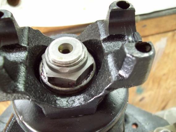
17 Once all adjustments and setup are complete, remove the nut, washer and yoke and install the new pinion seal. I like to use a VERY light coating of gasket sealer around the seal before carefully tapping it into the case. Before putting the yoke back on, I THOROUGHLY clean the splines of the pinion and yoke and paint gasket sealer in the splines of the yoke to seal against any oil leaking through the splines. Put the yoke back on, then the washer and nut. 17

18 Holding tool 18


19 When I first setup the pinion with the new crush sleeve, BEFORE installing the new seal, I only tighten the nut to achieve about 20 in/lbs preload on the pinion bearings. Once the seal is installed and the yoke, washer and nut are finally installed, I also use gasket sealer on the washer and nut, then finish tightening the pinion nut to achieve the 25 in/lbs specified in the rear-end manual. 20 in/lbs 25 in/lbs 19


20 Finally finished: Tom Parsons 20
 When rebuilding a FACTORY style positraction unit (made for GM by DANA), it is VERY IMPORTANT to have the splines of the 2-piece axle gears lined up BEFORE pulling the 2 case halves")
21 Here is an additional picture that I didn't include in the original information. ( When rebuilding a FACTORY style positraction unit (made for GM by DANA), it is VERY IMPORTANT to have the splines of the 2-piece axle gears lined up BEFORE pulling the 2 case halves together with the 8 bolts. It is TOOOOOOOO EASY to do! You need 2 axles to do this with, or the splined ends from 2 junk axles. Insert each axle end ALLLLLLLL the way into both sides of the posi unit, assuring that they go all the way through BOTH of the 2-piece axle gears. I place an axle in the vice, and then insert the end of a junk axle in the other side of the posi unit and start tightening the bolts, finally torqueing them to 45lbs. If the splines are not aligned when the posi unit is being reassembled, it may be VERY difficult to get the axles back into the axle housing because they cannot go into the splines of the second part of the axle gears. 21


22 Here is what the 2 parts of the axle gears look like when the axle splines are inserted into both parts. Tom Parsons 22


23 The Nitro Power Lock Positraction Unit: :21 PM - Post# UPS delivered 2 Nitro Power Lock posi units today. Here is my assessment after inspecting one of the units. At first glance, the Nitro posi unit looks like the original GM/DANA unit. However, there are some changes which, in my opinion, are very nice improvements. The Nitro units only come in a 3-series version. To use it with 4.11-up gears, it will be necessary to either use thick ring gears, or, use a ring-gear spacer. Here are two overall views of the Nitro unit: 23


24 Here is a comparison of the internal axle gears of the DANA (left) and the Nitro axle gears: DANA Nitro 24
.")
.")
25 The axle gears of the original DANA unit are 2-piece whereas the Nitro axle gear is ONE piece. This is an improvement; PLUS, an added benefit is that it is not necessary to assure that each pair of axle-gear splines is lined up (as was described above). The splines for the clutch plates are slightly longer on the Nitro axle gear. Another improvement! All 10 (5 per side) clutch plates are the THICK versions (one Belleville per side). There are NO thin plates. What this means is that the clutch plate pocket on each half of the unit must be machined slightly deeper (maybe about 0.030in per side???). I like the idea of all plates being the same thickness. The bolts are RIGHT-HAND FINE-THREAD (grade 8), as opposed to left-hand threads on the original DANA units. The benefit is that it will be much easier to obtain regular grade 8 fine thread bolts if replacement is needed. Below is the Nitro unit separated to show its internal parts. 25

26 Five clutch plates of equal thickness. There is ONE very minor down-side, but to me it s a non-issue. If this unit is used in a axle housing along with axles, then it will STILL be necessary to cut off 1/8 inch from the splined end of each axle. The price of the Nitro unit is comparable to the Eaton unit, however, if you are installing an Eaton posi unit in a axle housing, it won't be necessary to trim the axles. Is this a better unit than an Eaton? I don't have an opinion. BUUUUUUUUUUUUT, I like the design of the one-piece Eaton case. In the past, I have seen DANA posi units with all 8 bolts sheared. The internal parts/gears of the Nitro unit can be purchased separately, which is good, and they can also be used to upgrade an original DANA unit. Tom Parsons 26

27 Servicing the 1956 Passenger Car Rear Axle Pg
CONVERTING NON POSI REAR END TO POSI Chevrolet passenger car and Corvette
 By Tom Parsons CONVERTING NON POSI REAR END TO POSI 55 64 Chevrolet passenger car and 56 62 Corvette This article will be specifically directed at converting the 55-64 Chevrolet full size pass car and
PPM-D44538RJK JK Rear 5.38 Ring and Pinion Installation Instructions Version 1
 PPM-D44538RJK JK Rear 5.38 Ring and Pinion Installation Instructions Version 1 GENERAL NOTES: Gear set up and installation should be performed by someone experienced in gear and axle set up Special tools
Critical Areas of Setup: Although there are many steps to differential repair, there are 4 critical areas of setup that all differentials share:
 DISASSEMBLY: Integral style with rear cover (aka salisbury) 1. Support vehicle or rearend on suitable lift or stands. 2. Drain oil by removing differential cover. 3. Remove wheels, brake drums, rotors
DRIVE AXLE - INTEGRAL HOUSING
 DRIVE AXLE - INTEGRAL HOUSING 1993 Toyota Celica 1993 DRIVE AXLES Toyota Differentials & Axle Shafts - Integral Housing Toyota; Celica All-Trac DESCRIPTION Drive axle assembly is a hypoid type with integral
DRIVE AXLE Nissan 240SX DESCRIPTION & OPERATION AXLE RATIO & IDENTIFICATION AXLE SHAFT & BEARING R & I DRIVE SHAFT R & I
 DRIVE AXLE 1990 Nissan 240SX 1990 DRIVE AXLES Rear Axle - R200 240SX, 300ZX DESCRIPTION & OPERATION The axle assembly is a hypoid type gear with integral carrier housing. The pinion bearing preload adjustment
CHEVROLET 12-BOLT PASSENGER CAR
 Ring and Pinion Sets We offer complete coverage of ratios for your 12-bolt rears. The first letter of the part number indicates manufacturer. The last three numbers are the gear ratios. 8.875 Ring Gear
REMOVAL & INSTALLATION
 REMOVAL & INSTALLATION AXLE SHAFTS & BEARINGS Removal CAUTION: Failure to turn off air suspension power before raising vehicle may result in unexpected inflation or deflation of air springs. DO NOT reconnect
BW 9-bolt positraction cone repair
 BW 9-bolt positraction cone repair Article & photos by 88 350 tpi formula, GM Tech, Editing by Duck [Hawaii], Rev 5, Nov. 30, 2004 This article describes how to repair the posi cones used in Borg Warner
COMPONENTS REAR DIFFERENTIAL COMPONENTS
 COMPONENTS REAR DIFFERENTIAL COMPONENTS REMOVAL 1. Drain the differential gear oil. 2. Remove the rear disk brake. 3. Remove the parking brake and cable. 4. Remove the stabilizer bar. 5. Pull out the
The Ryan Overdrive by Tom Endy
 The Ryan Overdrive by Tom Endy The Ryan overdrive is a factory built overdrive designed for the Model a Ford. They were manufactured in Denver, Colorado and marketed between 1990 and 2000. They were discontinued
1994 Mitsubishi Eclipse GS
 APPLICATIONS CHRYSLER MOTORS MANUAL TRANS OVERHAUL - MITSUBISHI W5M & W6M SERIES MANUAL TRANSMISSIONS Mitsubishi W5M31, TRANSMISSION APPLICATIONS (CHRYSLER MOTORS) Vehicle Application Transmission Model
ADVANCE ADAPTERS INC. Fixed Yoke kit (S.Y.E. Kit)
") ADVANCE ADAPTERS INC. Fixed Yoke kit (S.Y.E. Kit) Instruction Sheet P/N: 50-7905 & 50-7906 KIT CONSISTS OF: No. Qty Part No. Description 1. 1 51-7906 TAILHOUSING, DIECAST 2. 1 52-7905 SHAFT, MAIN OUTPUT
ADVANCE ADAPTERS INC. Fixed Yoke kit (S.Y.E. Kit) Instruction Sheet P/N: 50-7905 & 50-7906 KIT CONSISTS OF: No. Qty Part No. Description 1. 1 51-7906 TAILHOUSING, DIECAST 2. 1 52-7905 SHAFT, MAIN OUTPUT
DRIVE AXLE - 4WD MODELS WITH INTEGRAL HOUSING
 DRIVE AXLE - 4WD MODELS WITH INTEGRAL HOUSING 1988 Toyota Celica DRIVE AXLES Toyota Integral Housing Celica (Rear) DESCRIPTION housing. Drive axle assembly is hypoid type with integral carrier AXLE RATIO
Installation Kit Instructions
 Installation Kit Instructions Please read completely before beginning. Over the years we have gathered information from Gleason gear design manuals, Dana Spicer instruction manuals, technical bulletins,
PROPELLER SHAFT & DIFFERENTIAL CARRIER SECTIONPD CONTENTS
 PROPELLER SHAFT & DIFFERENTIAL CARRIER SECTIONPD CONTENTS PREPARATION...2 PROPELLER SHAFT...5 On-Vehicle Service...6 Removal and Installation...7 Inspection...7 Disassembly...7 Assembly...8 ON-VEHICLE
LoMax 205 CASE & 3:1 GEAR SET. Manufactured by JB CONVERSIONS, INC. Phone: Installation Instructions for the GM NP205 Transfer Case
 LoMax 205 CASE & 3:1 GEAR SET Part No. 2800 Instruction Rev: 2007.08.16 Manufactured by JB CONVERSIONS, INC. Phone: Installation Instructions for the GM NP205 Transfer Case Kit Components: 1. (1) 42x25
DIFFERENTIALS & AXLE SHAFTS
 DIFFERENTIALS & AXLE SHAFTS 2001 Chevrolet Camaro 2000-01 DRIVE AXLES General Motors Differentials & Axle Shafts Chevrolet; Camaro Pontiac; Firebird DESCRIPTION & OPERATION Drive axle is a semi-floating,
INSTALLATION KIT INSTRUCTIONS
 INSTALLATION KIT INSTRUCTIONS Please read completely before beginning This installation guide was written to provide the novice and professional with easy guidelines for differential setup. Over the years
ADVANCE ADAPTERS INC. P/N: NP231 SHORT SHAFT "FIXED YOKE" KIT
 Paso Robles, CA 93447 PAGE 1 OF 10 Telephone: (800) 350-2223 Fax: (805) 238-4201 Page Rev. Date: 06-24-02 KIT CONSISTS OF: No. Qty Part No. Description 1. 1 51-7906 TAILHOUSING, DIECAST 2. 1 52-7905 SHAFT,
DF 78. HINT: Face the rough side of the thrust washer marked by # to the differential case. INSPECTION
 78 DIFFERENTIAL REAR DIFFERENTIAL CARRIER ASSEMBLY (w/ Differential Lock) Face the rough side of the thrust washer marked by # to the differential case. INSPECTION 1. DIFFERENTIAL SIDE GEAR (w/ LSD Differential)
Amarillo PUMP DRIVES (250 HP THROUGH 350 HP) INSTRUCTIONS FOR REPAIRING MODELS 250, 300, and 350
 INSTRUCTIONS FOR REPAIRING MODELS 250, 300, and 350") Amarillo PUMP DRIVES (250 HP THROUGH 350 HP) INSTRUCTIONS FOR REPAIRING MODELS 250, 300, and 350 Amarillo Right Angle Pump Drives, if properly installed and maintained, should provide years of service
Amarillo PUMP DRIVES (250 HP THROUGH 350 HP) INSTRUCTIONS FOR REPAIRING MODELS 250, 300, and 350 Amarillo Right Angle Pump Drives, if properly installed and maintained, should provide years of service
Mustang Differential Gears - Installation Instructions
 Mustang Differential Gears - Installation Instructions The below installation instructions work for the following products: Ford Racing Gears - 3.73 Gears for 8.8" Ford Rear End Ford Racing Gears - FRPP
M Ring and Pinion Installation
 !!! PLEASE READ ALL OF THE FOLLOWING INSTRUCTIONS CAREFULLY PRIOR TO INSTALLATION. Axle Shaft Removal (1994-2012 Mustang typical) STEP 1: STEP 2: Remove the 10 differential housing cover bolts and drain
Instructions to install the early ( ) Limited Slip Differential in the Late-model ( ) G28 Transaxle
 Limited Slip Differential in the Late-model ( ) G28 Transaxle") Instructions to install the early (1978-83) Limited Slip Differential in the Late-model (1985-1995) G28 Transaxle BACKGROUND: Most 928 owners know about the improvements to the 5- speed transaxle that
Instructions to install the early (1978-83) Limited Slip Differential in the Late-model (1985-1995) G28 Transaxle BACKGROUND: Most 928 owners know about the improvements to the 5- speed transaxle that
Take off case cover.
 33 14 520 Removing complete locking differential. (Type K) - final drive removed - Removing and installing final drive, refer to 33 10 010 Drain off fluid. Secure final drive to special tool 33 1 010 (retaining
*Some speedometers have these additional electronic connections. If yours does, then remove the smaller slotted screws shown.
 www.odometergears.com 1981-1985 240 Cable-Driven Speedometers (NOT for 1986 and later electronic units) http://www.davebarton.com/240-odometer-repair.html For this set of instructions below, I will not
NP231 SHORT SHAFT "FIXED YOKE" KIT FOR NON-CV YOKES AND FLANGE YOKES
 KIT CONSISTS OF: No. Qty Part No. Description 1. 1 51-7906 TAILHOUSING, DIECAST 2. 1 52-7905 SHAFT, MAIN OUTPUT 3. 1 300474 SEAL WASHER, REAR YOKE 4. 1 300476 NUT, REAR YOKE 5. 1 300480 SEAL WASHER, FRONT
SISU DP-330 DRIVE GEAR. Maintenance Manual
 SISU DP-330 DRIVE GEAR Maintenance Manual Sisu Axles, Inc. Autotehtaantie 1 PO Box 189 Fin-13101 Hameenlinna Finland Phone +358 204 55 2999 Fax +358 204 55 2900 DP330DG.PDF (3/2007) TABLE OF CONTENTS
NP231 SHORT SHAFT "FIXED YOKE" KIT
 Page 1 of 11 KIT CONSISTS OF: No. Qty Part No. Description 1. 1 51-7905 TAILHOUSING, DIECAST 2. 1 52-7905 SHAFT, MAIN OUTPUT 3. 1 300474 SEAL WASHER, REAR YOKE 4 1 300475 YOKE, C.V. REAR 5. 1 300476 NUT,
DISASSEMBLY AND ASSEMBLY
 205-03-1 Front Drive Axle/Differential Ford 8.8-Inch Ring Gear 205-03-1 DISASSEMBLY AND ASSEMBLY Axle Front Drive Special Tool(s) 2-Jaw Puller 205-D072 (D97L-4221-A) Special Tool(s) Carrier Bearing Replacer
Steer Axles. Spicer. Service Manual. AXSM-0070 November Front Drive Steer Axle Model 60
 Spicer Steer Axles Service Manual AXSM-0070 November 2017 Front Drive Steer Axle Model 60 General Information The description and specifications contained in this service publication are current at the
Gearbox Assembly 101. Introduction. Before Beginning. By Mark Schutzer 4/13/06
 Gearbox Assembly 101 By Mark Schutzer 4/13/06 Introduction If you are planning to re-motor an old brass locomotive you may want to upgrade to a new gearbox at the same time. The early 60 s and 70 s gearboxes
Take off case cover.
 33 14 520 Replacing complete locking differential (Type M) - final drive removed - Removing and installing final drive, included in Repair Manual MF, model-dependent, from '85, refer to 33 10 010. Drain
DRIVE AXLE Volvo 960 DESCRIPTION & OPERATION AXLE IDENTIFICATION DRIVE AXLES Volvo Differentials & Axle Shafts
 DRIVE AXLE 1994 Volvo 960 1994 DRIVE AXLES Volvo Differentials & Axle Shafts 960 DESCRIPTION & OPERATION All 960 station wagon models use type 1041 rear axle assembly. All 960 4-door models use type 1045
23.Front Differential Assembly
 23.Front Differential Assembly A: REMOVAL 1) Remove the manual transmission assembly. 2) Prepare the transmission for overhaul.
Ford 9 XD Aussie-Locker Install Instructions.
 Ford 9 XD-45831 Aussie-Locker Install Instructions. Before the install check the following. 1. Must be 31 spline 4-pinion carrier. 2. Must be an open carrier not a limited slip. 3. Refer to Ford or vehicle
Rear Axle Assembly Rebuild Pictorial 2015 by Tom Endy
 Rear Axle Assembly Rebuild Pictorial 2015 by Tom Endy The following series of photos were taken during the rebuild of a Model A rear axle assembly. Bearings, races, seals, gaskets and new shackle bushings
1999 F-150/250 Workshop Manual
 Page 1 of 30 SECTION 205-03: Front Drive Axle/Differential Ford 8.8-Inch Ring Gear 1999 F-150/250 Workshop Manual DISASSEMBLY AND ASSEMBLY Procedure revision date: 01/08/2003 Axle Front Drive Special Tool(s)
SA 82 Front Differential (Disassembly and Assembly of Differential w/ ADD) Disassembly and Assembly of Differential (with A.D.D.)
 Disassembly and Assembly of Differential (with A.D.D.)") SA82 SUSPENSION AND AXLE Disassembly and Assembly of Differential (with A.D.D.) DISASSEMBLY OF DIFFERENTIAL 1. REMOVE ACTUATOR (a) Remove the four bolts. (b) Using a hammer, remove the actuator. SA83 2.
SA82 SUSPENSION AND AXLE Disassembly and Assembly of Differential (with A.D.D.) DISASSEMBLY OF DIFFERENTIAL 1. REMOVE ACTUATOR (a) Remove the four bolts. (b) Using a hammer, remove the actuator. SA83 2.
TO INDEX DIFFERENTIAL FRONT DIFFERENTIAL CARRIER OIL SEAL (4WD) FRONT DIFFERENTIAL CARRIER ASSEMBLY (4WD) REAR DIFFERENTIAL CARRIER OIL SEAL
 FRONT DIFFERENTIAL CARRIER ASSEMBLY (4WD) REAR DIFFERENTIAL CARRIER OIL SEAL") TO INDEX DRIVE LINE / AXLE DIFFERENTIAL DIFFERENTIAL SYSTEM PRECAUTIONS.............................................. OPERATION CHECK......................................... PROBLEM SYMPTOMS TABLE.................................
TO INDEX DRIVE LINE / AXLE DIFFERENTIAL DIFFERENTIAL SYSTEM PRECAUTIONS.............................................. OPERATION CHECK......................................... PROBLEM SYMPTOMS TABLE.................................
PROPELLER SHAFT & DIFFERENTIAL CARRIER SECTIONPD CONTENTS IDX. PROPELLER SHAFT...3 Preparation...3 C200. REAR FINAL DRIVE...40 Preparation...
 PROPELLER SHAFT & DIFFERENTIAL CARRIER SECTIONPD GI MA EM LC EC CONTENTS FE PROPELLER SHAFT...3 Preparation...3 SPECIAL SERVICE TOOLS...3 Noise, Vibration and Harshness (NVH) Troubleshooting...4 NVH TROUBLESHOOTING
Ball splines can be configured for an endless number of automated operations. Demystifying Ball Spline Specs
 Ball splines can be configured for an endless number of automated operations. Demystifying Ball Spline Specs Place a recirculating-ball bushing on a shaft and what do you get? Frictionless movement of
TL REPAIR MANUAL. Telma model FV61-00 (FU831310) replacement on Dana 19060S axle. Page 1 of 8 30jun10
 replacement on Dana 19060S axle. Page 1 of 8 30jun10") TL103035 REPAIR MANUAL Telma model FV61-00 (FU831310) replacement on Dana 19060S axle Page 1 of 8 30jun10 Exploded view TL103035 Stator carrier Telma Unit Flange Yoke Page 2 of 8 30jun10 Disassembly 1.
TL103035 REPAIR MANUAL Telma model FV61-00 (FU831310) replacement on Dana 19060S axle Page 1 of 8 30jun10 Exploded view TL103035 Stator carrier Telma Unit Flange Yoke Page 2 of 8 30jun10 Disassembly 1.
Suzuki Samurai to Toyota Front Spring Swap Kit, with Missing Link Shackles (SKU#SSP-TSFM) Installation Instructions
 Installation Instructions") Suzuki Samurai to Toyota Front Spring Swap Kit, with Missing Link Shackles (SKU#SSP-TSFM) Installation Instructions CAUTION: Safety glasses should be worn at all times when working with vehicles and related
Suzuki Samurai to Toyota Front Spring Swap Kit, with Missing Link Shackles (SKU#SSP-TSFM) Installation Instructions CAUTION: Safety glasses should be worn at all times when working with vehicles and related
TROUBLESHOOTING SPECIAL TOOL ASSEMBLY AND ADJUSTMENT
 1 INDEX Models FD, FE, FF and SG REAR AXLE 10-1 10-108E-07 CHAPTER 10 REAR AXLE Models FD, FE, FF and SG TROUBLESHOOTING...10-2 10 SPECIAL TOOL...10-3 WHEEL HUB AND RELATED PARTS DISASSEMBLY...10-7 INSPECTION...10-9
STERNDRIVE UNIT 3 B GEAR HOUSINGS MR/ALPHA ONE/ALPHA ONE SS
 STERNDRIVE UNIT 3 B 23146 GEAR HOUSINGS MR/ALPHA ONE/ALPHA ONE SS Table of Contents Page Identification........................... 3B-1 Specifications.......................... 3B-1 Torque Specifications................
TRANSMISSION PARTS Instructions
 TRANSMISSION PARTS Instructions Sure Cure Kit Part No. SC-4T65E GM 4T65-E Valve Body Parts Boost Valve Kit 84754-30K Patent No. 6,832,632 TCC Apply Valve Kit 84754-43K Patent No. 7,100,753 TCC Regulated
AUSSIE LOCKER. Aussie lockers are 100% made in the USA. Installation Supplement for Carrier Clearance Dana 35 Models (XD & XD-13530)
") AUSSIE LOCKER Aussie lockers are 100% made in the USA. Installation Supplement for Carrier Clearance Dana 35 Models (XD-13527 & XD-13530) Table of Contents Table of Contents... 2 Introduction... 3 Installation
AUSSIE LOCKER Aussie lockers are 100% made in the USA. Installation Supplement for Carrier Clearance Dana 35 Models (XD-13527 & XD-13530) Table of Contents Table of Contents... 2 Introduction... 3 Installation
REAR DIFFERENTIAL LOCATION INDEX
 2007 DRIVELINE/AXLES Differential - MX-5 Miata REAR DIFFERENTIAL LOCATION INDEX Fig. 1: Identifying Location Of Rear Differential Components DIFFERENTIAL OIL INSPECTION 1. Park the vehicle on level ground
MANUAL TRANSMISSIONS Mitsubishi F4M20, F5M20, F5M30 & KM200 Series TRANSMISSION APPLICATION
 Article Text ARTICLE BEGINNING MANUAL TRANSMISSIONS Mitsubishi F4M20, F5M20, F5M30 & KM200 Series APPLICATION TRANSMISSION APPLICATION Vehicle Application Transmission Model Chrysler Motors (2WD) 4-Speed
Transmission Overhaul Procedures-Bench Service
 How to Assemble the Lower Reverse Idler Gear Assembly Special Instructions In 1996 Eaton changed the reverse idler system design. In the nut design, the reverse idler bearing was lubricated through a hole
Part # Mustang Complete HQ Series Coil-Over Kit
 350 S. St. Charles St. Jasper, In. 47546 Ph. 812.482.2932 Fax 812.634.6632 www.ridetech.com Front Components: Part # 12090210 64-66 Mustang Complete HQ Series Coil-Over Kit 1 12093509 HQ Series Front Coil-Overs
60-65 Falcon, Comet & Ranchero Coil Spring IFS
 60-65 Falcon, 62-65 Comet & 62-65 Ranchero Coil Spring IFS All engine installations with this front end will require a rear sump oil pan. 289-302 Small Block Ford Motors Milodon rear sump pan holds 7 quarts
REAR AXLE Click on the applicable bookmark to selected the required model year
 REAR AXLE 27-2 REAR AXLE General Information GENERAL INFORMATION 27100010118 The rear axle is a banjo-type semi-floating type. The axle shaft bearings are: *Single taper bearings for vehicles without
Mikuni RS Carburetor Conversion
 Mikuni RS Carburetor Conversion After putting your carbies on the bench or the kitchen table if the wife is out, you will see that the linkages may be in different positions depending on which brand of
Purposes of a Drive Axle Assembly
 Differentials Purposes of a Drive Axle Assembly To transmit power from the drive shaft to the wheels To turn the power flow 90 degrees on RWD cars To allow the wheels to turn at different speeds while
-7 I Remove the brake shoe return springs.
 REAR AXLE 9-A.REAR AXLE SHAFT... 9: 1 9.A.1. Removing Rear Axle Shaft... 9 : 1 9.A.2 Disassembling Rear Axle Shaft... 9 : 2 9.A.3. Inspecting Rear Axle Shaft and Bearing... 9 : 3 9.A-4 Assembling Rear
13. DRIVE TRAIN 13-0 DRIVE TRAIN MXU 500
 13 DRIVE TRAIN SERVICE INFORMATION------------------------------------------------ 13-2 TROUBLESHOOTING----------------------------------------------------- 13-2 FRONT DRIVE SHAFT REMOVAL/INSPECTION/ INSTALLATION
DIFFERENTIAL. OL = Overall Length
 3 Rear Axle Shafts Blazer 3- Jimmy 3-34-4 REAR AXLE SHAFT -/ GEAR WD BLZ JIM 3- ().44 4. 34- REAR AXLE SHAFT -/ GEAR WD BLZ JIM - () 4.4. 34- REAR AXLE SHAFT -/ GEAR 4WD BLZ JIM 3- ().44 4. 34- REAR AXLE
The many different faces of the T5
 The many different faces of the T5 Not all Borg Warner/TREMEC T-5's are the same. The first T-5 five speeds were introduced to market in 1980, in all things, an AMC Spirit/Concord. In 1983, T-5's were
SECTION Front Drive Axle/Differential
 205-03-i Front Drive Axle/Differential 205-03-i SECTION 205-03 Front Drive Axle/Differential CONTENTS PAGE Axle... 205-03-2 205-03-2 Front Drive Axle/Differential 205-03-2 Axle Special Tool(s) C-Frame
STERNDRIVE UNIT 3 A DRIVE SHAFT HOUSING
 STERNDRIVE UNIT 3 A 23262 DRIVE SHAFT HOUSING Table of Contents Page Specifications............................ 3A-1 Torque Specifications.................. 3A-1 Upper Drive Shaft Bearing Preload.......
REAR AXLES CONTENTS. Page SERVICE DIAGNOSIS. torque. Damaged gears. (k) Replace gears as required. (c) Clean breather thoroughly. (d) Oil seals worn.
 Replace gears as required. (c) Clean breather thoroughly. (d) Oil seals worn.") REAR AXLE GROUP 3 CONTENTS Page DESCRIPTION 1 SERVICE DIAGNOSIS 1 SERVICE PROCEDURES 1 SURE GRIP DIFFERENTIAL. SPECIFICATIONS AND TIGHTENING REFERENCE Page. 15 (In Back of Manual) Description The rear
REAR AXLE GROUP 3 CONTENTS Page DESCRIPTION 1 SERVICE DIAGNOSIS 1 SERVICE PROCEDURES 1 SURE GRIP DIFFERENTIAL. SPECIFICATIONS AND TIGHTENING REFERENCE Page. 15 (In Back of Manual) Description The rear
X GM / Chevrolet Model 70 /267 Rear Axles for. C-30 DRW G-Van, SRW G-Van G-Van Extended G-300 K-30 P-30, P-300 R-30 V-30
 GM / Chevrolet 1979-1994 Model 70 /267 Rear Axles for C-30 DRW G-Van, SRW G-Van G-Van Extended G-300 K-30 P-30, P-300 R-30 V-30 261 Exploded View 262 Parts Listing ITEM NO. PART NUMBER DESCRIPTION 1 (3)
Turbo 400 Trans Brake Valve Body Shift Pattern: Park Reverse Neutral 1st 2nd 3rd
 TCI 221500 Turbo 400 Trans Brake Valve Body Shift Pattern: Park Reverse Neutral 1st 2nd 3rd This Valve Body will neutralize at shut-down by putting shifter In 2nd gear position This Kit Contains: (1) Turbo
Re-building a Caliper
 Re-building a Caliper by Leslie Henson The pistons in the calipers on the 90 are in very poor condition, and although the brakes work ok, it plays on our mind that the pistons are badly corroded, and it
AMARILLO PUMP DRIVES MODEL 1 OOOA, 1200, 1500, 1800
 AMARILLO PUMP DRIVES MODEL 1 OOOA, 1200, 1500, 1800 INSTRUCTIONS FOR REPAIRING MARCH 1, 1993 AMARILLO GEAR COMPANY Post Office Box 1789, Amarillo, Texas 79105 806 / 622-1273 FAX 806 / 622-3258 INSTRUCTIONS
Mopar 8 3/4 & 9 3/4 (Dana) Installation Instructions Rear Disc Conversion
 Installation Instructions Rear Disc Conversion") Mopar 8 3/4 & 9 3/4 (Dana) Installation Instructions Rear Disc Conversion This kit is for either Mopar 8 ¾ or Mopar 9 ¾ (Dana). This kit is designed to work with axles with either GM 5 x 4.75 Bolt Pattern
Mopar 8 3/4 & 9 3/4 (Dana) Installation Instructions Rear Disc Conversion This kit is for either Mopar 8 ¾ or Mopar 9 ¾ (Dana). This kit is designed to work with axles with either GM 5 x 4.75 Bolt Pattern
Corvette Set Separator (Glove Box) Lock Removal
 Lock Removal") 1956-62 Corvette Set Separator (Glove Box) Lock Removal The materials here were gathered from several Corvette Forum Threads as well as from the Web Pages of Rich Mozzetta (rich5962 on the CF). Our colleagues
1956-62 Corvette Set Separator (Glove Box) Lock Removal The materials here were gathered from several Corvette Forum Threads as well as from the Web Pages of Rich Mozzetta (rich5962 on the CF). Our colleagues
DF 43 DIFFERENTIAL REAR DIFFERENTIAL CARRIER ASSEMBLY REMOVAL
 DIFFERENTIAL REAR DIFFERENTIAL CARRIER ASSEMBLY 43 REMOVAL 1. DISCONNECT CABLE FROM NEGATIVE BATTERY TERMINAL 2. REMOVE REAR WHEEL 3. DRAIN BRAKE FLUID 4. REMOVE REAR BRAKE DRUM SUB-ASSEMBLY (See page
'99-03 CHEVROLET/GMC IFS 4WD 6" SUSPENSION SYSTEM P/N INSTALLATION INSTRUCTIONS
 1/16/04 '99-03 CHEVROLET/GMC IFS 4WD 6" SUSPENSION SYSTEM P/N. 10-41099 INSTALLATION INSTRUCTIONS NOTE: Each Lift Kit and options to Lift Kits are packaged separately. Therefore, installation procedures
Timing the 9N/2N Steering Sector Gears
 Timing the 9N/2N Steering Sector Gears by John Korschot - www.johnsoldiron.com (May 2010) The procedure for timing a set of steering gears in the 9/2n tractors is published in the I&T FO4 shop manual.
Converting a Series Land Rover to front wheel disc brakes using the kit made by Torrel Industries Ltd,
 Converting a Series Land Rover to front wheel disc brakes using the kit made by Torrel Industries Ltd, Torrel Industries ltd Series Land Rover front brake conversion kit: Difficulty - Low Except for one
Detroit Speed, Inc. Mini-Tub Kit Chevy Nova, Oldsmobile Omega, Pontiac Ventura P/N: &
 Detroit Speed, Inc. Mini-Tub Kit 1968-74 Chevy Nova, Oldsmobile Omega, Pontiac Ventura P/N: 041207 & 041208 Item Component Quantity 1 DSE Mini Tubs 1968-74 X-Body 2 2 Rear Upper Shock Crossmember 1 3 Upper
Part # Mustang Coil-Over System
 350 S. St. Charles St. Jasper, In. 47546 Ph. 812.482.2932 Fax 812.634.6632 www.ridetech.com Front Components: 1 12093509 HQ Series Front Coil-Overs Part # 12090201 64-66 Mustang Coil-Over System 1 12099599
Installation Manual Clayton Off Road Suspension: XJ 6.5 Coil Conversion Long Arm Lift Kit Jeep Cherokee Last Revision No.: 3/1/11 PN
 Thank you for purchasing a Clayton Off Road suspension. Please check to make sure you have all necessary parts before you start your install. XJ 8.0 Coil 1100107 3 Link Bridge W/mount 1100108 Front Spring
Chevrolet Generator Rebuild and Restoration
 Rich Mozzetta PDF compiled by Dave Zuberer Chevrolet Generator Rebuild and Restoration I had 2 old Chevy generators and I used parts from both to create a new one for a 1960 Corvette project. Both generators
SECTION 3A FRONT DRIVE AXLE TABLE OF CONTENTS SPECIFICATIONS GENERAL SPECIFICATIONS. Description Drive Shaft Type. CV Joint Axle Housing Type
 SECTION 3A FRONT DRIVE AXLE TABLE OF CONTENTS Specifications........................ 3A-1 General Specifications.................. 3A-1 Fastener Tightening Specifications......... 3A-2 Component Locator...................
1984 Dodge W250 PICKUP
 1984 Dodge W250 PICKUP Submodel: Engine Type: V8 Liters: 5.2 Fuel Delivery: CARB Fuel: GAS Dana 44 MODELS THROUGH 1984 2. Raise and safely support the vehicle, then remove the wheel hub and bearings as
1967 (Late) CORVETTE STANDARD (NON-ADJUSTABLE) STEERING COLUMN DISASSEMBLY & REPAIR INSTRUCTIONS PAPER #2
 CORVETTE STANDARD (NON-ADJUSTABLE) STEERING COLUMN DISASSEMBLY & REPAIR INSTRUCTIONS PAPER #2") Last Revision: 03SE2012 1967 (Late) - 1968 CORVETTE STANDARD (NON-ADJUSTABLE) STEERING COLUMN DISASSEMBLY & REPAIR INSTRUCTIONS PAPER #2 Disassembly and Repair Instructions Addressed in this Paper Degree
Last Revision: 03SE2012 1967 (Late) - 1968 CORVETTE STANDARD (NON-ADJUSTABLE) STEERING COLUMN DISASSEMBLY & REPAIR INSTRUCTIONS PAPER #2 Disassembly and Repair Instructions Addressed in this Paper Degree
Section II REAR AXLE CONTENTS
 REAR AXLE 1 Section II REAR AXLE CONTENTS Page Removal of Differential Carrier Assembly 5 Removing Drive Gear and Case Assembly 6 Drive Pinion and Bearing Disassembly 8 Pinion Bearing Pre-Load and Pinion
REMOVAL & INSTALLATION
 REMOVAL & INSTALLATION CENTER BEARING SUPPORT ASSEMBLY Removal 1. With transmission in neutral and parking brake off, raise vehicle. Scribe alignment marks on all flange/yokes and slip joints to be disassembled
DrVanos.com Stage II Installation Instructions. Tool rental is available with the purchase of a vanos kit *See website for more info*
 DrVanos.com Stage II Installation Instructions Special Tools Needed: Camshaft locking tool TDC Crank pin Sprocket turning tool Tool rental is available with the purchase of a vanos kit *See website for
XD Aussie Locker XD Installation Supplement Dana 35 Ford TTB
 XD-13527 Aussie Locker XD-13527 Installation Supplement Dana 35 Ford TTB Thank you for your purchase of the XD-13527 Aussie Locker for Dana 35 Ford TTB The following installation review is from username
This file is available for free download at
 This file is available for free download at http://www.iluvmyrx7.com This file is fully text-searchable select Edit and Find and type in what you re looking for. This file is intended more for online viewing
2 of 10. Bronco Parts. Dana 44 Yukon Hardcore Chrome Moly Axle Set $ Dana 44 Chrome Moly 4340 Axle Set With $325.00
 1 of 10 Next, remove the long main filter bolts and the 9 shorter VB bolts. Notice the correct location of the ID tag. This picture shows the throttle pressure limit valve and spring have not yet been
GROUP 3 REAR AXLE CONTENTS. Page SPECIFICATIONS
 REAR AXLE 3-1 GROUP 3 REAR AXLE CONTENTS Page Specifications 1 Special Tools. 2 Torque Reference < v v".-. 2 Axle Drive Shafts 3 Axle Drive Shaft End Play... 4 Differential Carrier- Removal "... 5 Differential
HAYS HYDRAULIC RELEASE BEARING INSTALLATION INSTRUCTIONS
 HAYS HYDRAULIC RELEASE BEARING INSTALLATION INSTRUCTIONS PRELIMINARY INSTALLATION NOTES IMPORTANT! DO NOT RETURN THIS PRODUCT TO YOUR DISTRIBUTOR. If you have questions, please review additional information
655 South Lincoln Avenue / San Bernardino CA Phone / Fax / Web address: globalwest.net
 655 South Lincoln Avenue / San Bernardino CA. 92408 Phone 877-470-2975 / Fax 909-890-0703 / Web address: globalwest.net Part # TBC-9 or TBC-10 --- 1963-82 Corvette Rear swing arm installation instructions:
Building a Bulletproof NP205 Tips and tricks for the toughest transfer case available. Photography by Rick Péwé 4Wheel & Off-Road, February, 2009
 Building a Bulletproof NP205 Tips and tricks for the toughest transfer case available. Photography by Rick Péwé 4Wheel & Off-Road, February, 2009 The venerable NP205 transfer case has a reputation for
GR 4.0 Liter To Chevy Trans Adapter Kit GR 4.0 Liter Bell Housing Adaptor GR 4.0 Liter Flexplate Adaptor
 Revision 12/20/12 1033040 1GR 4.0 Liter To Chevy Trans Adapter Kit 1033039 1GR 4.0 Liter Bell Housing Adaptor 1052025 1GR 4.0 Liter Flexplate Adaptor 1033039 Kit Contents 1 Bell housing Adapter Plate 2
Dodge Light Duty Axle Applications. X510-5 September, Supersedes X510-5DSD dated January 1999
 Dodge 1999-2001 Light Duty Axle Applications X510-5 September, 2001 Supersedes X510-5DSD dated January 1999 SAFETY INFORMATION WARNING - Failure to follow these instructions could affect vehicle performance
Maintenance Instructions
 General Note These instructions contain information common to more than one model of Bevel Gear Drive. To simplify reading, similar models have been grouped as follows: GROUP 1 Models 11, 0, 1,, (illustrated),,
1964 1/2-70 Mustang Torque Arm Rear Suspension Installation Instructions
 1964 1/2-70 Mustang Torque Arm Rear Suspension Installation Instructions 1-800-984-6259 www.totalcostinvolved.com Version 2 (c) 2008 Total Cost Involved Engineering, Inc. All Rights Reserved. Page 1 of
FRONT AXLE 26-1 CONTENTS GENERAL INFORMATION... 2 HUB AND KNUCKLE ASSEMBLY SERVICE SPECIFICATIONS... 4 DRIVE SHAFT LUBRICANTS...
 26-1 FRONT AXLE CONTENTS GENERAL INFORMATION.................. 2 SERVICE SPECIFICATIONS................. 4 LUBRICANTS.............................. 4 SEALANTS AND ADHESIVES.............. 5 SPECIAL TOOLS...........................
LIMITED SLIP DIFFERENTIALS MINI-SPOOLS SPOOLS
 LIMITED SLIP DIFFERENTIALS MINI-SPOOLS SPOOLS The answer to faster and smoother torque transfer, at any speed, in any driving condition INNOVATION AT WORK From over the road daily driving to muddy trails
DF 15. DIFFERENTIAL 1GR-FE FRONT DIFFERENTIAL CARRIER ASSEMBLY (for 4WD) REMOVAL
 REMOVAL") DIFFERENTIAL 1GR-FE FRONT DIFFERENTIAL CARRIER ASSEMBLY (for 4WD) 15 REMOVAL 1. REMOVE FRONT WHEELS 2. REMOVE REAR ENGINE UNDER COVER ASSEMBLY (a) Remove the 6 bolts and engine under cover assembly. 3.
DIFFERENTIAL 1GR-FE FRONT DIFFERENTIAL CARRIER ASSEMBLY (for 4WD) 15 REMOVAL 1. REMOVE FRONT WHEELS 2. REMOVE REAR ENGINE UNDER COVER ASSEMBLY (a) Remove the 6 bolts and engine under cover assembly. 3.
SA 66 Front Differential (Disassembly and Assembly of Differential w/o A D D ) Disassembly and Assembly of Differential (with out A.D.D.
 Disassembly and Assembly of Differential (with out A.D.D.") SA66 SUSPENSION AND AXLE Differential w/o A D D ) Disassembly and Assembly of Differential (with out A.D.D.) SUSPENSION AND AXLE Differential w/o A D D ) DISASSEMBLY OF DIFFERENTIAL 1. REMOVE DIFFERENTIAL
SA66 SUSPENSION AND AXLE Differential w/o A D D ) Disassembly and Assembly of Differential (with out A.D.D.) SUSPENSION AND AXLE Differential w/o A D D ) DISASSEMBLY OF DIFFERENTIAL 1. REMOVE DIFFERENTIAL
Dana Spicer Tandem Drive Axles
 Dana Spicer Tandem Drive Axles S400-S Service Manual AXSM-1951 September 1997 For the most current information, visit the Roadranger web site at www.roadranger.com TABLE OF CONTENTS Axle Identification...
HIGH PERFORMANCE TRANSMISSION PARTS Instructions. Line Pressure Booster Kit. TCC Control Plunger Valve Kit. Line Pressure Modulator Plunger Valve Kit
 Performance Pack Ford 4R100 Part No. HP-4R100-01 Line Pressure Booster Kit Line-to-Lube Pressure Regulator Valve Line Pressure Booster Kit Valve Sleeve O-Rings (2) TCC Control Plunger Valve Kit Front Lube/Drainback