|
|
|
- Christian Melton
- 5 years ago
- Views:
Transcription
1

2

3

4
5

6 American R/D SOLID WEDGE GATE VALVE C-500 2" THROUGH 96" SERIES 100 SERIES 105 2" Through 96" Ductile IRON Construction Full Waterway AWWA C-500 Rated up to 250 psi
7 100-LINE SOLID WEDGE GATE VALVE FEATURES The American R/D series 100-line is supplied in both NRS and OS&Y styles. The 100-line is a solid wedge NRS gate valve and the 105-line is a solid wedge OS&Y gate valve. Both series of valves are available in 2" through 96" NPS. Designed in accordance with AWWA C500 and applicable ANSI, ASTM and other industry standards. For higher pressure systems or highly corrosive environments the valves are produced in ductile iron or 3% nickel iron. All valves 16" NPS and larger are designed with bronze body and wedge guides. Available with hand wheels, operating nuts and when required, integrally cast mounting pads for gears or electric actuators. Valves are protected externally and internally with coatings conforming with AWWA C500. The American R/D Gate 100-Line Solid Wedge NRS Gate Valve and 105-Line Solid Wedge OS&Y have three standard features: Conforms with AWWA C500, ANSI B16.1-Class 125 Drilling Available with flanged, MJ or grooved ends Working pressure: 2"-12" NPS up to-250 p.s.i. max., 14"-96" NPS up to-150 p.s.i. max. Bronze trim with 304 stainless steel stems Bronze body and wedge guides in all valves 16" NPS and larger One piece solid wedge design SAMPLE SPECS Gate valves for wastewater and sewage applications should be designed and produced in accordance with AWWA C500. Pressure containing components should be ductile iron ASTM A536, GR 65/45/12. Wedge seating surfaces and body seat rings are to be cast from ASTM B62 bronze. Stems should have integral collars and be machined from corrosion resistant stainless steel conforming with grade 304 or materials offering equal or greater physical and material properties. All valves 16" NPS or larger require bronze body and wedge guides with a length equal to at least 50 percent of the normal pipe size. Body and bonnet fastener should be of External and internal protective coatings Valves may be produced with accessories such as by-passes, cleanouts, indicators, rollers, tracks and scrapers, extension stems, and floorstands. Ductile iron construction For stress corrosion environments we can supply stainless steel grade 304 or 316 seats and disc. rustproof material having the physical properties of ASTM A307. Packing and gaskets shall be of non-asbestos materials. Valves are to be designed with minimal moving parts to prevent clogging or excessive build-up of foreign matter. Valve coatings should be consistent with AWWA C500. Testing and inspections shall conform to AWWA C500 section five. Valves should be marked with the requirements of AWWA C500. Valves to be equal in all respects to the American R/D AWWA Solid Wedge Gate Valve, 100 Series for NRS style and 105 Series for OS&Y style. D100-LINE SOLID WEDGE HIGH PRESSURE GATE VALVE FEATURES The American R/D series D100-line is a solid wedge NRS gate valve available in nominal pipe sizes 2" through 48". Designed in accordance with AWWA C500 and applicable ANSI, ASTM and industry standards. Constructed of ductile iron ASTM A536 GR65/45/12 with bronze trim and 304 stainless steel stems. All valves 16" NPS or larger are designed with bronze body and wedge guides. Available with handwheels, operating nuts and when required, integrally cast mounting pads. Valves are protected externally and internally with coatings conforming with AWWA C500. The American R/D D100-Line Solid Wedge Gate Valve has these standards features: Conforms with AWWA C500, ANSI B16.1-Class 250 Drilling Available with flanged or MJ ends Working pressure: 2"-48" NPS up to-250 p.s.i. max. Valves may be produced with accessories such as by-passes, cleanouts, indicators, rollers, tracks and scrapers, extension stems and floorstands. SAMPLE SPECS Gate valves for wastewater and sewage applications should be designed and produced in accordance with AWWA C500. Pressure containing components should be cast from ductile iron ASTM A536 GR65/45/12. Wedge seating surfaces and body seat rings are to be cast from ASTM B62 bronze. Stems should have integral collars and be machined from corrosion resistant stainless steel conforming with grade 304 or materials offering equal or greater physical and material properties. All valves 16" NPS or larger require bronze body and wedge guides with a length equal to at least 50 percent of the normal pipe size. Body and bonnet Bronze trim with 304 stainless steel stems Bronze body and wedge guides in all valves 16" NPS and larger One piece solid wedge design External and internal protective coatings For stress corrosion environments we can supply stainless steel grade 304 or 316 seats and disc. fasteners should be of rustproof material having the physical properties of ASTM A307. Packing and gaskets shall be of nonasbestos materials. Valves are to be designed with minimal moving parts to prevent clogging or excessive build-up of foreign matter. Valve coatings should be consistent with AWWA C500. Testing and inspections shall conform to AWWA C500 section five. All valves should be hydrostatically seat tested to 300 psi minimum. Valves should be marked with the requirements of AWWA C500 section six and MSS-SP25. Valves to be equal in all respects to the American R/D Solid Wedge D100AWWA Series,

8 100-LINE SOLID WEDGE GATE VALVE Valve available in NRS or OS&Y, in sizes 2"-96" Series 100 and 105 2"-12" rated up to 250 psi and 14-96" rated up to 150 psi. Series D100 2"-48" rated up to 250 psi Available with class #125 and #250 drilling, flange, mechanical Joint, grooved and any combination O-ring design and/or adjustable Teflon impregnated packing available on NRS and OS&Y configurations Heavy duty full body wall thickness made in Ductile Iron Solid one piece tapered wedge assures excellent performance and prevents clogging Liquid applied epoxy coating inside and exterior with industry accepted coatings Full flow waterway Full wedge guides engage with body guides to maintain parts in position: 16" and larger sizes use bronze wedge end body guides Close fitting stem to wedge engagement maintains components aligned Extra wide bronze surfaces on disc and seat ring provide large seating area Corrosion resistant one piece stem made of high strength stainless steel May be manufactured with: bypasses, integral cast flushing ports/cleanouts, Stainless steel grade 304 or 316 seating surfaces, rollers-tracks-scrapers, extension stems, floor stands, accuators, and position indicators. Rollers, tracks and scrapers recommended for horizontal applications over 16" in size.
9 American R/D In-Plant Products 3"-72" Rotating-Revolving Disc Gate Valves 2"-96" Solid Wedge Gate Valves 2"-48" Resilient Wedge Gate Valves 4"-30" Swing Check Valves 3"-24" Eccentric Plug Valves 4"-30" Flap Valves 4"-30" Shear Gates 4"-14" Sluice Gates 4"-24" Mud Valves Pressure Relief Valves- Wall & Floor In Plant Accessories Chainwheels Floorstands Stem Guides Extension Stems Actuators For dimensions and drawings of our 2"-96" Solid Wedge Gate valve, please contact American R/D at (256) American R/D 1800 Greenbrier Dear Rd. Anniston, Al Phone Fax A Division of McWane, Incorporated For Generations
10

11

12

13


14 Kennedy Swing Check Valves A.W.W.A. C508 was developed in 1976 to set a standard for the manufacture, testing and application of Iron Body Bronze Mounted (IBBM) Check Valves. The valves are designed with an iron body and include either metal-tometal or composition-to-metal seating. Kennedy Swing Check Valves are designed and manufactured in conformance with A.W.W.A. C508 and are for use on water, oil and gas lines. Under certain circumstances where it is desirable to have more positive control of the closing of the disc, the valves can be supplied with either lever-and-spring or lever-and-weight. For restricted spacing requirements Kennedy Valve manufactures a Wafer Check Valve that also helps to control water hammer. Features Swing Check Valve-AWWA Stainless steel hinge pin. Working parts are removable through the top of the valve. Tapped bosses available. Available with lever-and-spring or lever-and-weight. Double bronze side plug construction. Bodies are made of high strength cast iron with reinforced flanges ANSI B 16.1/125 # flanges. May be installed in a vertical line with the flow up. Figure #1106 Series 2"-12" Test Pressure Seat and Shell 400 PSI Working Pressure non-shock CWP 200 PSI Figure #106 Series 14"-24" Test Pressure Seat and Shell 300 PSI Working Pressure non-shock CWP 150 PSI Flow Versus Pressure Drop Data Representative of Fig and 1106A Updated 08/24/10 Kennedy Valve / Check Valves 15-1
15 Kennedy Check Valves It is generally recommended, that when using Kennedy swing check valves, that you locate the valve at least 5 to 10 pipe diameters down stream from any flow disturbance or obstruction (valve, pump, elbow, reducer, etc.). Turbulence close to the check valve may result in valve "chatter" resulting in premature failure of the check valve. As stated in AWWA C508, "Conditions of water hammer, hydraulic pulsation, and excessive operating noise are results of system design rather than valve design and are beyond the scope of this standard and require special design and construction considerations." 15-2 Kennedy Valve / Check Valves Updated 08/24/10
 Part No. Qty. Description Material & ASTM Spec.")
16 AWWA SWING CHECK VALVES 2"-12" TECHNICAL DATA & PARTS LIST Resilient/Bronze - Figure # 1106A, 1106AW, 1106AS KENNEDY VALVE Bronze/Bronze - Figure # 1106, 1106LW, 1106LS (1106A, 1106AW, 1106AS) (1106, 1106LW, 1106LS) Part No. Qty. Description Material & ASTM Spec. 1A With 2 Side Plug With O-Ring Bronze 1AB (O-Ring) 1 for LS/LW 2A * SEE FOOT NOTE Cap Bolts Stainless Steel, ASTM F593C (18-8) 3A 1 O-Ring Syn. Rubber 4A 1 Cap Cast Iron, ASTM A126 Class B 5A 1 Body Cast Iron, ASTM A126 Class B 6A 1 Hinge Pin SS A-276 (304) 7AA 1 Hinge Bronze (2'-3") D.I. A-536 (4"-12") 7AB 1 Hinge w/keyway for LS/LW Bronze (2"-3") Ductile Iron ASTM A536 (4"-12") 8AA 1 Disc Bolt (4"-12")*** Bronze (10"-12") Steel (4"-8") 8AB 1 Disc Bolt (4"-12")*** Bronze (10"-12") Steel (4"-8") 9AA 2 Disc Bolt O-Ring (4"-12" 1106A, 8"-12" 1106) Syn. Rubber 9AB 2 Disc Bolt Gasket (4" & 8" 1106) 10A 1 Disc Holder Bronze (2"-3") Cast Iron, ASTM A126 Class B (4"-12") 11A 1 Disc Plate Bronze 12AA 1 Disc Nitrile (Buna N) Rubber 12AB** 1 Disc Bronze (2"-3") Cast Iron, ASTM A126 Class B (4"-12") 13A 1 Disc Nut Stainless Steel, ASTM F593C (18-8) 2 w/resilient disc (2"-3") 14AA** 1 Disc Ring (4"-12") Bronze 15A 1 Seat Ring Bronze 16A 1 Spring Steel 17A 1 Extended Hinge Pin for LS/LW Stainless Steel, ASTM A-276 (304) 18A 2 Key for LS/LW Stainless Steel, ASTM A-276 (304 19A 1 Set Screw Steel 20AA 1 Lever Arm for LS Steel 20AB 1 Lever Arm for LW Steel 21A 1 Bracket Steel 22A 2 Hex Head Bracket Bolt Steel 23A 1 Eye Bolt w/2 Hex Nuts Steel 24A 1 Stuffing Box Bronze 25A Packing Graphite Filled 26A 1 Gland Bronze 27A 1 Weight Cast Iron, ASTM A126 Class B 28A 1 Set Screw Steel * **See Q on page 6. ** *Denotes that part is available only as part of an assembly. *** Cast inegral (2"-3"). Updated 08/24/10 Kennedy Valve / Check Valves 15-3

 A.W.W.A. KENNEDY BODY MARKINGS CAP MARKINGS YEAR KENNEDY SIZE (OPPOSITE SIDE) FIG.")
17 Dimensional Data 2"-12" 1106/1106LW/106LS AND 1106AW AND 1106AS AND 1106A * *Face to face dimensions conform to ASME B16.10 * SIZE A B C D E F G H J L M N Q* R 2" /2" " " " " " " (ONE SIDE) A.W.W.A. KENNEDY BODY MARKINGS CAP MARKINGS YEAR KENNEDY SIZE (OPPOSITE SIDE) FIG. NO. 200 W BOSS AND DRAIN TAPPING SCHEDULE VALVE SIZE (In.) / ,10,12 MAX. SIZE PIPE TAP (NPT) 3 / /4 2 When ordering Check Valves tapped for bypass or drain, specify exact location and size of tap using letters above for boss designation. These locations of drain and by-pass tappings conform to the Manufacturers Standardization Society Specification SP Kennedy Valve / Check Valves Updated 08/24/10 Conforms to MSS SP-71 and AWWA C508
18 SPRING AND LEVER CHECK VALVE STYLE NO /106ALS 16 LEVER AND WEIGHT CHECK VALVE STYLE NO /106ALW F PLAIN CHECK VALVE 14" STYLE NO /106A PART NO. A.S.T.M. NO. REQ D PART MATERIAL SPEC. NO. 1 1 Body Cast Iron A126 CL B 2 1 Cover Cast Iron A-126 CL B 3 1 Body Ring Bronze CDA Clapper 1 See Note No Clapper Arm Bronze B Clapper Stud Bronze B-21 7 Varies Clapper Nut Bronze CDA Hinge Pin Stn Stl. A Side Plug (Plain Valve) Bronze CDA Varies Cover Bolts & Nuts Steel A-307GR B 11 1 Cover Gasket Non-Asbestos 12 1 Clapper Ring Neoprene 13 2 Gasket Copper Non-Asbestos 14 2 Side Plug Gasket Copper Non-Asbestos 15 1 Weight Lever Arm 2 Cast Iron A-126 CL B 16 1 Weight Cast Iron A-126 CL B 17 1 Spring Lever Arm 3 See Note No Spring Steel 19 1 Spring Bracket Steel 20 1 Spring Eyebolt Steel A-307GR B 21 2 Stuffing Box Assembly Bronze CDA Capscrew Bolt Bronze B Clamping Ring Bronze CDA Lock Washer Steel 25 Varies Cotter Pin Bronze 26 2 Spring Bracket Cap Screw Steel A-307GR B 27 2 O Ring Side Plug Bronze CDA O Ring Rubber 14" SWING CHECK VALVE-RUBBER FACED- FLANGED END Kennedy Valve DRAWN BY CHECKED APPRoVED KM DATE 2/28/74 SCALE None DWG No REV. Kennedy Valve / Check Valves 15-5 Updated 08/24/10
19 SPRING AND LEVER CHECK VALVE STYLE NO /106LS LEVER AND WEIGHT CHECK VALVE STYLE NO /106LW PART NO. A.S.T.M. NO. REQ D PART MATERIAL SPEC. NO. 1 1 Body Cast Iron A-126 CL B 2 1 Cover Cast Iron A-126 CL B 3 1 Body Ring Bronze CDA Clapper Cast Iron A-126 CL B 5 1 Clapper Arm Bronze CDA Varies Lockwasher Steel 7 Varies Capscrew Bronze B Hinge Pin Stn. Stl. A Gland (Bronze Bushed) Cast Iron A-126CL. B 10 Varies Cover Bolt and Nuts Steel A-307GR B 11 1 Cover Gasket Non-Asbestos 12 1 Clapper Ring Neoprene 13 1 Ring Clamp Bronze CDA Varies Ring Clamp Capscrew Bronze B Weight Lever Arm Bronze B Weight Cast Iron A-126CL. B 17 1 Spring Lever Arm Bronze B Spring Steel 19 1 Spring Bracket Steel 20 1 Spring Eyebolt Steel A-307GR.B 21 1 Cap Plate Cast Iron A-126CL. B 22 Varies Spring Bracket Capscrew Steel A-307GR B 23 1 Lockwire Copper B DIMENSIONS IN INCHES VALVE SIZE E 25 3 /8 F / / /2 G 1 7 / / / /8 2 1 /8 H 23 1 / / /4 J 21 1 / / /2 36 K / / / /4 Q 27 1 / / / /4 R / /8 SPRING & LEVER VALVES S 17 3 / / / /8 LEVER & WEIGHT VALVES T 19 1 / / / /8 U 34 1 / / /2 1 PLAIN CHECK VALVE STYLE NO /106 16"-30" SWING CHECK VALVE-RUBBER FACED- FLANGED END KM Kennedy Valve DRAWN BY CHECKED APPRoVED DATE SCALE DWG No. None REV Kennedy Valve / Check Valves Updated 08/24/10


20 Kennedy Iron Swing Check Valves UL/FM Underwriters /Factory Mutual Underwriters Canada Kennedy Swing Check Valves are for use where backflow is to be prevented. The disc is designed with ample tolerances to compensate for seat ring wear. The spinning action of the disc creates a regrinding effect that cleans the seat ring of foreign particles. The disc is also self-adjusting. All moving parts of these valves are bronze to bronze, minimizing wear and corrosion problems. These valves are listed by Underwriters Laboratories and approved by Factory Mutual Fire Research Corp. and have body markings UL and FM signifying the listing and approval. Working Pressure: Cold Water, Non-Shock, 175 Lbs. (2 1 /2"-12") Hydrostatic Test Pressure: Seat and shell, 350 PSI. (2 1 /2"-12") Construction: Bronze Mounted with Bronze Disc or Resilient Disc Updated 08/24/10 Kennedy Valve / Check Valves 15-7

21 Iron Swing Check Valves Underwriters /Factory Mutual/ULC APPROVED BY N.Y.C. BOARD OF STDS. Bronze Mounted with: Rubber Faced Disc or Bronze Faced Disc Working Pressures: 2 1 /2"-12" Cold Water, Non-Shock, 175 lbs. Approvals: UL/FM/ULC 2 1 /2"-12" Fig and 1126A Factory Test Pressure: Seat and Shell 350 PSI End Flange Drilling: 125 LB American Standard Work with Page 15-9 FIG Fig. 126a Flanged Ends Common Parts: Use with all Figures Part No. Description Material A.S.T.M. Spec. 1 Cap Bolts Stainless Steel 18-8 F593C 2 Cap Cast Iron A-126 Class B 3 "O" Ring Buna "N" 5 Body Cast Iron A-126 Class B 6 Hinge Pin Stainless Steel A-276 (304) 7 Hinge Bushings Sint. Bronze + 4" Thru 12" 12 Seat Ring Bronze B Drain Plug Steel Socket 3/4" Pipe Plug@ A-126 Class B 28 Side Plugs with O-Ring 28A Bronze Rod B-16 28A O-Ring for Side Plug 28 Buna "N" + Cannot be ordered separately, only with Allen Wrench Req'd for Removal/Installation Fig Bronze Disc Assembly Sizes 2 1 /2" and 3" 8 Hinge Mang. Bronze B584 Alloy C Disc Nut Bronze Rod B Disc Bronze B-62 Fig Bronze Faced Disc Assembly Sizes 4" through 14" 14 O Rings Buna N 15 Disc Bolt Bronze Rod B Hinge Malleable Iron A Disc Malleable Iron A Disc Ring Bronze B-62* *Cannot be ordered separately. Fig. 1126A Rubber Faced Disc Sizes 2 1 /2" and 3" 29 Disc Holder Bronze B Disc 4,6 EPDM Rubber 30 Disc Plate Bronze Rod B Disc Nut (2 Req'd) Bronze Rod B Disc Bolt Bushing Sint. Bronze + +Cannot be ordered separately. Fig. 1126A Rubber Faced Disc Sizes 4" through 12" 20 Disc Holder Malleable Iron A Disc 8-12 Nitrile (Buna N) Rubber 22 Disc Plate Bronze B Disc Bolt Bronze Rod B Disc Nut (1 Req'd) Bronze Rod B O Rings Buna N 27 Disc Bolt Bushing Sint. Bronze + +Cannot be ordered separately, only with hinge. Common Reference Dimansions SIZE A B C D E F G R 2 1 / / / /32 3 / /4 3 /4 7 1 /2 6 5 /8 7 1 /2 7 /16 3 / / / /2 3 / / /8 3 / / / / /2 3 /4 3 / / / /4 1 3 /16 3 / / / /8 3 / WEIGHT POUNDS SIZE 21/2" 3" 4" 5" 6" 8" 10" 12" FIG FIG. 126A Kennedy Valve / Check Valves Updated 08/24/10
22 Iron Swing Check Valves Underwriters /Factory Mutual Underwriters Canada Bronze Mounted with Rubber Faced Disc or Bronze Faced Disc Exploded View A FIG Bronze Disc Assembly, Size 2 1/2" and 3" Center B FIG Bronze Faced Disc Assembly, Size 4" thru 12" Bottom C FIG. 1126A Rubber Disc Assembly, Size 4" thru 12" FIG. 1126A Rubber Disc Assembly, Size 2 1/5" and 3" - Not Shown See Page 15-8 for Detail. Also see Page 15-8 for Number Identification Updated 08/24/10 Kennedy Valve / Check Valves 15-9
 (OPPOSITE SIDE) size 300 Kennedy 706 year Part No. Qty. Description Material & ASTM Spec.")

23 Wafer Check Valves Technical/Dimensional Data Size A B C D E 4" " " BODY MARKINGS (ONE SIDE) (OPPOSITE SIDE) size 300 Kennedy 706 year Part No. Qty. Description Material & ASTM Spec. 1 1 Spring Stainless Steel, A-313 (302) 2 1 Hinge Pin Stainless Steel, A-276 (304/316) 3 2 Side Plug Bronze 4 1 Body Cast Iron A-126 Class B 5 2 O-Ring Syn. Rubber 6* 1 Seal Syn. Rubber 7* 1 Seat Ring Bronze 8 1 Clapper Bronze *Denotes part is only available as part of an assembly. Features Wafer Check Valve-UL/FM Short laying length. Spring loaded for more effective control of water hammer. Stainless steel spring. Resilient seating. Easy maintenance with a minimum number of parts. Built-in O-Ring flange seals gaskets not required. Mounts between standard ANSI B 16.1/125 lb. flanges. Mounting between 250 lb. flanges requires use of spacers. May be installed in a vertical line with flow up or down. Testing Test Pressure Seat and Shell 600 PSI Working Pressure Non-Shock 300 PSI Figure # Kennedy Valve / Check Valves Updated 08/24/10


24 Kennedy Wafer Check Valves UL-FM/A.W.W.A/ULC APPROVED BY N.Y.C. BOARD OF STDS. Sizes 4, 6 & 8 Inch Iron Body Bronze Disc Resilient Seating O Ring End Seals Working Pressure: 300 PSI, Non-Shock Compact, for installation between standard flanges, Kennedy WAFER CHECK VALVES have spring loaded bronze discs, resilient seating, and utilize O rings rather than gaskets for end seals. HYDROSTATIC TEST PRESSURE: Seat and Shell 600 PSI. UL LISTED/FM APPROVED ULC LISTED fig. 706 DET. DESCRIPTION QTY. MATERIAL and ASTM SPEC. 01 Spring 1 Stainless Steel ASTM 313-AISI Type Hinge Pin 1 Stainless Steel ASTM A276-AISI Type 302/ Side Plug 2 Bronze 04 Valve Body 1 Cast Iron ASTM A126 Class B 05 O Ring 2 BUNA-N-ASTM D Seal 1 BUNA-N, U/L Seat Ring 1 Bronze ASTM B Clapper 1 Aluminum Bronze ASTM B806 Alloy C95400/C95500 WT. Size A B C D E LBS. F G WT Updated 08/24/10 Kennedy Valve / Check Valves 15-11


25 Grooved Check Valves FIGURE 426 UL LISTED/FM APPROVED SIZES 2 1 /2", 3", 4", 6", 8" Working Pressure: 250 PSI The Kennedy Figure 426 Grooved End Swing Check Valve is a lightweight unit that features a top access cover for field maintenance. The valves are intended to be easily installed with approved grooved couplings. They may be installed either with the flow in a vertical position or horizontally. All valves have a 1 /2" NPT connection on the inlet side for installation of a 1 /2" Ball drip. PARTS LIST ITEM NO. QTY. PART NAME MATERIAL 1 1 Valve Body Ductile Iron 2 3 Nut Plated 3 1 Cover Cast Iron 4 3 Bolt Plated 5 1 Cover Seal SBR Duro Hinge Support Stainless Steel 7 2 Nut Stainless Steel 8 2 Washer Red Fiber 9 2 Hinge Support Bolt Stainless Steel 10 1 Hinge Pin Stainless Steel 11 1 Hinge Stainless Steel 12 1 Valve Disk EPDM 13 1 Disk Plate Stainless Steel 14 1 Disk Holder Cast Iron * 15 1 Disk Nut Stainless Steel 16 1 Seal Washer Red Fiber ** 17 1 Disk Bolt Stainless Steel 18 1 Seat Ring Tin Plated Bronze 19 1 Drain Plug Zinc Plated **6 and 8 in. sizes only (others are integral to hinge) **2.5, 3 and 4 in. sizes only DIMENSIONAL DATA Height Width A B 2.5" = " = " = " = " = Weight/Pounds 2.5" = 19 lb. 3" = 21 lb. 4" = 29 lb. 6" = 61 lb. 8" = 81 lb Kennedy Valve / Check Valves Updated 08/24/10
26 Kennedy Grooved Check Valves RISER CHECK VALVE FIGURE 426 R UL LISTED / FM APPROVED SIZES 2 1 /2", 3", 4", 6" Working Pressure: 250 PSI The Kennedy Figure 426 R Grooved Check Valve may also be used as a Riser Check Valve. This valve would be a lightweight substitute for an Alarm Valve Assembly. The valve is intended to be installed vertically in a sprinkler riser, with appropriate trim (optional purchase). Each valve is tapped 1 /4" NST both above and below the clapper for pressure gauges, and 1 1 /4" or 1 1 /2" NSP (depending on valve size) for the drain outlet. Features: Complete size range 2 1 /2"-6" 250 PSI Rating EPDM Disc, Ductile Iron Body & Clapper 304 S.S. Clapper Assembly Top Entry Design Friction Loss 2 1 /2" GPM 3" GPM 4" GPM 6" GPM Updated 08/24/10 Kennedy Valve / Check Valves 15-13

27 NOTES: 1. 6" VALVE SHOWN 2. VALVE SHOWN WITH CUSHION ARRANGEMENT ON RIGHT HAND SIDE (FACING INLET) LEFT HAND VERSION AVAILABLE 3. VALVE OPENING IS SUDDEN INSTALL GUARDS OR OTHERWISE ASSURE THAT PERSONS ARE WELL CLEAR 4. DIMENSIONS ARE APPROXIMATE and FOR LAYOUT PURPOSES ONLY 5. CONFIGURATION FOR VERTICAL INSTALLATION DIFFERENT THAN SHOWN See Page ITEM NO. DESCRIPTION 1 Body Gray Iron A126 B Special Boss Drill & Tap 2 Cap Gray Iron A126 B 3 Cap Gasket Rubber Reinforced by GARLOCK 4 Cap Bolts & Nuts Steel, Plated A307 5 Seat Ring Bronze CDA Stuffing Box Bronze B16 8 Packing (not shown) Non-Asbestos by GARLOCK 9 Gland Follower Bronze B16 10 Hinge (Keyed) Ductile Iron 11M Disc Metal Iron 11R Disc Holder Iron 12M Disc Facing Ring Bronze CDA 844 Intergral with Disc 12R Disc, Resilient Rubber 13R Disc Plate Bronze CDA Disc Bolt Sizes 2-8" Steel 10&12" Bronze 15 Nut, Disc Bolt Sizes 2-8" Steel 10&12" Bronze 16 Disc Bolt Gasket Fibre 10&12" Sizes Use O-Ring 17 Hinge Pin (Special) Stainless 431 Heat Treated 18 Lever (Special) Steel 19 Key for Lever Stainless 20 Set Screw for Lever Steel 21 Key for Hinge Stainless 22 Weight Gray Iron A126 B 23 Set Screw for Weight Steel, Plated A Cylinder Arm Steel 25 Set Screw for Arm Steel 26 Body Bracket Steel 27 Outer Cylinder Bracket Steel 28 Inner Cylinder Bracket Steel 4 & 6" Sizes 29 Cylinder Per Catalogue 30 Bushing(s) Bronze 31 Rod End Steel 32 Pin Steel 33 Cotter Pin Stainless 34 Control Valve Per Catalogue 35 Nipple Brass 36 Muffler Per Catalogue 37 Body Bracket Bolts Steel, Plated Grade 5 38 Cylinder Bracket Bolts Steel, Plated Grade 5 39 Lock Washer (HiCollar) Steel, Plated 40 Nuts (Jam) Steel, Plated SIZE A D E CC1 CC2 CC3 CC4 CC5 CC6 CC Dimensions Approximate For Checking Clearances Only Allow Clearance Two Sides to Remove Side Plug & Access Hinge Pin ASSEMBLY DRAWING CUSHION CHECK SIZES 4"-12" FLOW HORIZONTAL Kennedy Valve DRAWN BY CHECKED APPRoVED L2C DATE 9/15/96 SCALE None DWG No REV. Cushion Check (Must specify vertical or horizontal installation when ordering) If possible, it is preferable to eliminate water hammer. The best way to eliminate water hammer is in the design of the piping system. For most cases where water hammer exists it is preferable to reduce its effects by causing the check valve to close so quickly that the flow is not able to reverse. Kennedy Valve makes a Figure 706 Wafer Check Valve that is intended as an anti-water hammer valve. Kennedy Valve also has available lever and weight and lever and spring arrangements on the Figure 1106 Check Valve. In some cases the customer may want an arrangement that retards the closing of the check valve. The customer may want such an arrangement for those cases where the water column actually has an opportunity to reverse or even separate, such as might occur when the check valve is not at the lowest elevation in the system Kennedy Valve / Check Valves Updated 08/24/10
28 NOTES: 1. 6" VALVE SHOWN 2. VALVE SHOWN WITH CUSHION ARRANGEMENT ON RIGHT HAND SIDE (FACING INLET) LEFT HAND VERSION AVAILABLE 3. VALVE OPENING IS SUDDEN INSTALL GUARDS OR OTHERWISE ASSURE THAT PERSONS ARE WELL CLEAR 4. DIMENSIONS ARE APPROXIMATE and FOR LAYOUT PURPOSES ONLY 5. CONFIGURATION FOR VERTICAL INSTALLATION DIFFERENT THAN SHOWN See Page ITEM NO. DESCRIPTION 1 Body Gray Iron A126 B Special Boss Drill & Tap 2 Cap Gray Iron A126 B 3 Cap Gasket Rubber Reinforced by GARLOCK 4 Cap Bolts & Nuts Steel, Plated A307 5 Seat Ring Bronze CDA Stuffing Box Bronze B16 8 Packing (not shown) Non-Asbestos by GARLOCK 9 Gland Follower Bronze B16 10 Hinge (Keyed) Ductile Iron 11M Disc Metal Iron 11R Disc Holder Iron 12M Disc Facing Ring Bronze CDA 844 Intergral with Disc 12R Disc, Resilient Rubber 13R Disc Plate Bronze CDA Disc Bolt Sizes 2-8" Steel 10&12" Bronze 15 Nut, Disc Bolt Sizes 2-8" Steel 10&12" Bronze 16 Disc Bolt Gasket Fibre 10&12" Sizes Use O-Ring 17 Hinge Pin (Special) Stainless 431 Heat Treated 18 Lever (Special) Steel 19 Key for Lever Stainless 20 Set Screw for Lever Steel 21 Key for Hinge Stainless 22 Weight Gray Iron A126 B 23 Set Screw for Weight Steel, Plated A Cylinder Arm Steel 25 Set Screw for Arm Steel 26 Body Bracket Steel 27 Outer Cylinder Bracket Steel 28 Inner Cylinder Bracket Steel 4 & 6" Sizes 29 Cylinder Per Catalogue 30 Bushing(s) Bronze 31 Rod End Steel 32 Pin Steel 33 Cotter Pin Stainless 34 Control Valve Per Catalogue 35 Nipple Brass 36 Muffler Per Catalogue 37 Body Bracket Bolts Steel, Plated Grade 5 38 Cylinder Bracket Bolts Steel, Plated Grade 5 39 Lock Washer (HiCollar) Steel, Plated 40 Nuts (Jam) Steel, Plated SIZE A D E VC1 VC2 VC3 VC4 VC5 VC6 VC NA NC Dimensions Approximate For Checking Clearances Only Allow Clearance Two Sides to Remove Side Plug & Access Hinge Pin ASSEMBLY DRAWING CUSHION CHECK SIZES 4"-12" FLOW UP Kennedy Valve DRAWN BY CHECKED APPRoVED L2C DATE 9/15/96 SCALE None DWG No V REV. For those customers, Kennedy Valve makes available the Figure 1206 Cushion Check Valve. The Figure 1206 Cushion Check Valve is a Figure 1106, AWWA valve with a lever and weight and a pneumatic cylinder arrangement. The pneumatic cylinder has a needle valve that allows the customer to adjust the time required for the valve to close. The Figure 1206 Check Valve may be ordered from the factory either as flow horizontal or flow up. The cylinder arrangement is available mounted on either side unless specified the Figure 1206 valve will be supplied with the cylinder on the right side (when facing the inlet) and for horizontal flow. The Figure 1206 has internal components identical to the Figure 1106 except that the hinge pin is made from heat treated, type 431 stainless steel and is unique to the Figure Updated 08/24/10 Kennedy Valve / Check Valves 15-15
29 KENFLEX RESILIENT HINGED CHECK VALVE FIG Kennedy Valve / Check Valves Updated 08/24/10
30 POSITION INDICATOR POA (NOT SHOWN) Part No Part Material NO. Req'd 1 1 body ductile iron 2 1 cover plate Ductile Iron 3 1 FLAPPER RESILIENT flapper, met. insert 4 varies cover bolts and nuts steel 5 1 back flow jack subassembly steel components SIZE A ØB C D ØE F G H I (aprox) (nom.) (nom.) Updated 08/24/10 L004 Kennedy Valve / Check Valves 15-17
31 FEATURES: Utilizes same components as the 106 Swing Check Valve 200 Working Pressure 400 Test Pressure Available in sizes: 4 x 6, 4 x 8, 6 x 8, 6 x 10, 8 x 10, 8 x 12, 10 x 12 Resilient Seat (Rubber Disk, Bronze Seat) Ring Available in either Plain, Lever & Spring or Lever & Weight H SIZE A B C D E F G APPROX. I J K L M N P Q R 4X X X X X X X INCREASING CHECK DIMENSIONS W/LEVER & WEIGHT PMP Kennedy Valve DRAWN BY CHECKED APPRoVED DATE SCALE DWG No. None REV Kennedy Valve / Check Valves Updated 08/24/10
32 FEATURES: Utilizes same components as the 106 Swing Check Valve 200 Working Pressure 400 Test Pressure Available in sizes: 4 x 6, 4 x 8, 6 x 8, 6 x 10, 8 x 10, 8 x 12, 10 x 12 Resilient Seat (Rubber Disk, Bronze Seat) Ring Available in either Plain, Lever & Spring or Lever & Weight SIZE A B C D E F G H I J K L M N 4X X X X X X X INCREASING CHECK DIMENSIONS W/SPRING & LEVER PMP Kennedy Valve DRAWN BY CHECKED APPRoVED DATE SCALE DWG No. None REV. Updated 08/24/10 Kennedy Valve / Check Valves 15-19


33 Kennedy Valve GUARD YOUR WATER SYSTEM FROM ACCIDENT OR ATTACK Patriot Hydrant Check Valve Threats to water supply can come from either accidental or deliberate acts. Our nation s water superintendents have safeguarded nearly all of the access points to our drinking water. At this time one critical access point left unprotected is the fire hydrant. The Patriot Hydrant Check Valve prevents reverse flow through the fire hydrant, safely protecting our drinking water while providing a full port unobstructed waterway that allows our firefighters the water they need when they need it. Unlike locks and special external devices, the Patriot is installed underground which prevents tampering and allows the hydrant to be operated the moment the firefighters arrive on the scene. The Patriot check valve can be installed on any 6" mechanical joint connection, nec ensuring compatibility with all hydrant brands providing the flexibility and cost effectiveness you demand. Updated 08/24/10 Kennedy Valve


, with NSF approved")


34 Specifications 1. The Patriot Fire Hydrant Check Valve shall be manufactured to all of the testing and performance standards of AWWA C508 and AWWA C550. The Check Valve shall be designed for 250 PSI working pressure and tested to 500 PSI hydrostatic pressure. 2. The Check Valve shall be a stand alone unit able to be positively restrained to any 6" mechanical joint fire hydrant shoe. 3. The Check Valve shall be ductile iron ASTM Standard A536 ( ), with NSF approved fusion bonded epoxy coating (interior/exterior). 4. The Check Valve shall be lead free, with no exposed lead bearing surfaces. 5. The Check Valve shall have an unobstructed waterway. No reduction of port or redirection of flow will be allowed. 6. The seat shall be retained via a double dove tail o-ring retaining groove design to ensure a positive seal. 7. The Check Valve shall incorporate integral positive restraint connections that maintain a restrained connection between the fire hydrant and the gate valve. 8. The Check Valve shall incorporate a stainless steel spring that hastens positive closure and prevents water hammer. 9. All fasteners shall be 304 stainless steel and all interior rubber components shall be EPDM rubber. 10. The Check Valve shall be produced with no less than 80% post consumer recycled content while being cast, manufactured, assembled and tested in the United States of America. Kennedy Valve Updated 08/24/10 PUB_PHC2_309

35 Kennedy Valve A Division of McWAne, inc e. Water street elmira, new York P.o. Box 981 Phone: (607) fax: Updated 08/24/10


36


37


38


39


40


41

42 CONCORD D-73 DAIG-O-PER UNDER PRESSURE DRILLING MACHINE Designed for installing water services with D-46 saddle or conventional corporation stops and separate saddles. Machine No Capacity: 3/4" and 1" Machine No Capacity: 1 1/4" - 1 1/2" - 2" Working pressure 200 p.s.i. First choice of the "man-in-the-trench" because the "0-73" is: CONVENIENT... For all watermains SIMPLE... Few components EASY TO OPERATE... With thrust bearing VERSATILE... For most popular types of connections STRONG... Manganese bronze barrel, handle, adapters ECONOMICAL... Less expensive, less maintenance cost LIGHT WEIGHT... Machine only 9 Ibs. approx. CLOW CLOW CANADA

43 CONCORD D-73 DAIG-O-PER PARTS PART NUMBER REF. NO DESCRIPTION BARREL FEED TUBE THRUST BEARING AND PLATES FEED TUBE HANDLE STEM DRIVE NUT STEM "0" RING (2) (INSIDE BARREL) ALLEN SCREW "0" RING (OUTSIDE BARREL) EQUIPMENT SUPPLIED WITH EACH MACHINE PART NUMBER REF. NO DESCRIPTION ALLEN KEY WRENCH (OPEN ENDS) RATCHET SOCKET 1" HEX. 1/2" DR. STEEL CASE Blades OPTIONAL EQUIPMENT (To be selected) REF. NO. 15 PART NUMBER 3/4" I 1" I 1 1/4" I 11/2" I 2" 7331 I 7332 I 7333 I 7334 I 7335 BLADE DESCRIPTION OPTION NO.1 When using 0-41 Saddle-stop PART NUMBER REF. NO. 3/4" 1" 11/4" 11/2" 2" DESCRIPTION ADAPTER I.P.T. MALE N/A N/A N/A ADAPTER WWT. MALE OPTION NO.2 - When using saddle and corporation stop PART NUMBER REF. NO. 3/4" 1" 11/4" 11/2" 2" DESCRIPTION ADAPTER, FEMALE FOR COPPER FLARED JOINT 7386 STEM EXTENSION 2 1/4" STEM EXTENSION 2 3/4" 7388 STEM EXTENSION 4 1/2" NOW AVAILABLE FOR PVC PIPES CLOW Hamilton, CLOWCANADA HEAD OFFICE WESTERN CANADA EASTERN CANADA 1757 Burlington Street East P.O. Box 1000 P.O. Box 700 P.O. Box Smelter Ave. S.E. Saint John, NB E2L 4B3 ant. L8H 3L5 Medicine Hat, AB T1A 7H1 Tel: (506) Tel: (905) Tel: (403) Fax: (506) Fax: (905) Fax: (403)

44 ( CONCORD (,! CURB BOXES, TOOLS and ACCESSORIES CLew CLOWCANADA
45 CLOWCANADA NOW AVAILABLE WITH ANTI-CORROSION STAINLESS UPPER SECTION AND EPOXY FINISH 0-11 Brass 0-10 Ribbed Pentagon Plug -- Cover Upper Section 1" diameter Standard or Stainless Steel Rod ( Ductile Iron or Welded "U" Clip Brass or Stainless Steel Cotter Pin Cast Iron Base -... ERIE/ECLIPSE PATTERN (BOTTOM ADJUSTMENT) D-1 Cast iron Base D-2 Cast Iron Base - for 1/2", 5/8", 1" Services - for 1 1 /4", ", 2" Services

46 CURB BOX LIDS D-10 Regular ribbed cover and brass pentagon plug. D-10A Ribbed repair cover c/w set screw and brass pentagon plug. D-10D 1%" ribbed cover and brass pentagon plug. D-10DR 1%" ribbed repair cover with set screw and brass pentagon plug. D-10F Flat cover with 1" brass thread. NOTE: Brass hexagon plugs available on all models if specified. CURB BOX PARTS D-11 ( D D-17F Brass pentagon or hexagon plug (specify) Frost ring washer Brass or stainless steel cotter pin Base for D-1, D-6, cast iron Base for D-1 P, D-6P, polyethylene Base for D-2, D-7, cast iron Base for D-8, cast iron. Standard repair coupling with two set screws. Repair coupling with one female end threaded and one end with set screw D-18 D-18A Extensions 1" male end threaded and female end with set screw. Fixed length-1" pipe. 6,12,18,24,30,36,42,48inches. Same as above-1 %" pipe fully adjustable within each length. SHUT OFF KEYS D-12 Combination Key For flat lids, pentagon or hexagon plugs Standard sizes: 30", 48", 60", 72" Longer sizes available upon request D-13 D-14 Standard Key Standard sizes: 30", 48", 60", 72" Longer sizes available upon request. Service Box Cleaners Eliminates digging up box to reach curb stop D-19 Double Key 5" x 5" or 10" x 10" Fits pentagon and hexagon plug.
 SIZE EXT IN FT.")
47 STATIONARY RODS FOR SERVICE BOXES T-5 T-4 T-2 T-8 9/16" 1/2" 5/8" 5/8" Std. Rod c/w Welded "U" Clip and Brass Cotter Pin. Type 304 Stainless Steel Rod c1w Welded "U" Clip. Brass or Stainless Steel Cotter Pin. Std. Rod c/w Ductile "U" Clip and Brass Cotter Pin. Std. Rod c/w Welded "U" Clip and Brass Cotter Pin. SIZES AVAILABLE WEIGHTS (LBS) SIZE EXT IN FT. ROD WITH ROD WITHOUT ROD NO. MIN-MAX LENGTH D-1P % 12" " %-3% 12" " %-4% 24" " %-5% 36" " %-6 1 /2 48" " %-7% 60" " %-8% 72" c9 84" %~9% 84" " %-10% 96" " I \~ Vllhen Ordering Specify: 1) Model Number 2) Depth of bury 3)Type and length of stationary rod from charts above. CLew Hamilton, HEAD OFFICE WESTERN CANADA EASTERN CANADA 1757 Burlington Street East P.O. Box 1000 P.O. Box 700 P.O. Box Smelter Ave. S.E. Saint John, NB E2L 4B3 Ont. L8N 3R5 Medicine Hat, AB T1A 7H1 Tel: (506) CLOWCANADA Tel: (905) Tel: (403) Fax: (506) Fax: (905) Fax: (403) Printed in Canada
48 L W CLOW CANADA D-1 SERVICE BOX PENTAGON PLUG D-1 SERVICE BOX LID SERVICE BOX BASE SPRING CLIP D-1 SERVICE BOX BASE 1/2", 5/8" & 1" SERVICES SERVICE BOX TUBE (UPPER SECTION) SERVICE BOX ROD COTTER PIN MADE IN CANADA
49 '.: :: ~ ;.; > :,", ',', CONCORD D 50 SEWER SADDLES When connecting 4", 5" or 6" AC or PVC building sewer pipes to AC, concrete or PVC mains 8" to 20". Larger sizes available upon request. Each Saddle fits a wide range of pipe O.D.'s A small inventory can therefore service all your installation needs. ---STAINLESS STEEL "0" RING r-... HEXAGONAL NUT ----(J'H /?--_CAST IRON J-+--BUNA N HALF MOON WASHER_--(. 4",5" OR 6" SADDLE-----;/ 1---CAST IRON RUBBER GASKET---v 1---NEOPRENE, HEXHEADBOLT-+ ~ STAINLESS STEEL HALF MOON WASHER WITH GROOVE ADJUSTABLE STRAP 45" long=8"-12" dia 72" long=14"-20" dia -\.:ll 1. The length of the stainless steel strap, assembled without welding, is determined by the nominal size of the sewer pipe main. 2. For a perfect seal, it is important to choose the proper "0" ring for building sewer pipe. By knowing the O.D. check the table below and choose the "0" ring you need. 3. IMPORTANT.- 4".' 6".'.,M)~~'::...:-"M A.~. ()"RING. "0" RING "II,. MIN: MAX..13} /32 '. ' ;5.65,0' 1/ ;650 Excess strap should not be cut off. Fold 5" excess strap inward toward and against main to form a secure pocket for the T-head bolt. Failure to fold strap inward may cause the strap to tear in installation. It is unnecessary to apply a torque load above 30 foot-pounds. CLew HEAD OFFICE WESTERN CANADA EASTERN CANADA 1757 Burlington Street East P.O. Box 1000 P.O. Box 700 P.O. Box Smelter Ave. S.E. Saint John, NB E2L 4B3 Hamilton. ON L8N 3R5 Medicine Hat. AB T1 A 7H 1 Tel: (506) Tel: (905) Tel: (403) Fax: (506) CLOWCANADA Fax: (905) Fax: (403) /4 Printed in Canada

50 D.73 PVC DAIG O PER -. UNDER PRESSURE DRILLING MACHINE Designed for installing water services with corporation stops and service saddles. Machrne No D73-1-PVC Capacity: % " and 1" Machine No D73-2-PVC Capacity: 1 W' - 1 W' - 1" _ Working pressure 200 psi. First choice of the "man-in-thearench" because the "D-73"is: - CONVENIENT... For all watermains - SIMPLE... Few components -EASY to OPERATE... With thrust bearing -. VERSATILE... For most popular types of connections - STRONG... Manganese bronze barrel, handle, adapters - ECONOMIICAL... Less expensive, less maintenance cost - LIGHTWEIGHT... -Machine only 9 Ibs. approx. ANOTHER... ~ '..... '-.' CL~W QUALITY,PRODUCT. CLOW~NADA

51 ",,, ".... D 73~PVCDAIG O PER PARTS., REF. NO. PART NUMBERS DESCRIPTION ' 7320 BARREL FEED TUBE THRUST BEARING AND PLATES FEED TUBE HANDLE STEM DRIVE NUT ' STEM "0" RING(2) (INSIDE BARREL) ALLEN SCREW "0" RING (OUTSIDE BARREL) EQUIPMENT SUPPLIED WITH EACH MACHINE, REF. NO. PART NUMBERS DESCRIPTION WRENCH (OPEN ENDS) RATCHET SOCKET 1" HEX, ~ DR, STEEL CASE OPTIONAL EQUIPMENT (To be selected) Shell Cutters I PART NUMBERS, REF NO. \'X" 1 " 1 ~" 1W 2" DESCRIPTION SHELL CUTTER OPTION No.1:'" For flared main stops PART NUMBERS REF NO. 'X" 1 " 1 ~" 1 ~ " 2" DESCRIPTION ADAPTERS.. OPTION No.2 For Mueller or Emco compression main stops PART NUMBERS REF NO. DESCRIPTION 'X" 1 " 1 ~ " 1 Y.;" 2" ms 7380ms ADAPTER,S To convert regular 0-73 to D-73-PVC machine 6 'X" & 1" 1 ~" & 1 W 2" or 6 & PVC PVC PVC i~~--~~~ ~----~~~~------~------{ 'HEAD OFFICE WESTERN-CANADA EASTERN ;:C~NADA " CLCW CLOWCANADA -" 600 Kenilworth'Ave, N:. P:O,'Box tooo P,O, Box7bO:, _ P,O. Box 2849, 801 Smelter Ave, S.E. Saint John, NB E2L4B.3 Hamilton, Ont.L8N 3R5 'Medidne 'Hat, AB. HA7H1 Tel:: (506) Tel: (416) 548'9604 ' 'Tel: (403) 52' ' Fax: (506) ~$4 "8936.' Fax: (416) 548"6885 Fax (403) 527 ~7454

52

53 A groundbreaking alternative to conventional distribution poles. If you're unhappy with the consistency and durability of wood poles, but can't justify the cost of steel or concrete, McWane Ductile Iron Poles are the perfect solution. Our durable, eco-friendly poles are a groundbreaking alternative to conventional distribution poles. Why Use Ductile Iron Poles? - Durability - our ductile iron poles are highly corrosion resistant and have an extended service life. -low Maintenance - strong, lightweight, and corrosion resistant, McWane poles are not affected by rot, insects, freezing weather, or woodpeckers. - Consistent Strength - unlike wood, our ductile iron poles are engineered with a minimum yield strength of 42 ksi. - low Investment - McWane ductile iron poles cost less than steel or concrete poles. - Green Solution - our poles are composed of recycled materials, and can be recycled after the end of their long service life. - Simple Installation - Ductile iron poles can be easily drilled. The round, tapered design simplifies orientation for installers.
. '\" Co C1J U 80.")
54 Properties of Ductile Iron: Yield strength (minimum psi) 42,000 Ultimate strength (minimum psi) 60,000 Elongation (minimum %) 10% Modulus of elasticity (ksi) 25,000 Coating Options: Ci) Co :i: Embed section: ~ 1. Metalized zinc base coat with ceramic epoxy top coat, 'i:> C1J feet above the ground line (standard embed coating). '" Co C1J U 80.0 Wood Pole Equivalents - Class B Above ground: No coating, weathered appearance Metalized zinc base coat with gray acrylic barrier coat above grade, exterior only. 0.0.j!.'--+---l---}-...==I==--I-==<"""""+~9f==.~+-.-J 3. Other color options available for large quantity orders. o Distance From Tip (tt) Other Information: Attachment holes can be pre-drilled to meet customer - Class 1 - Class 2 - Class 3 - Class 4 requirements. All poles provided with ground lug and - Class 5 - McWane Class 2 - McWane Class 3 nameplate.
 (inches) (inches) Capacity (ft-kips) C145W 45' 38 1003 0,26 7 13,3 3 106 C150W 50' 33 1245 0,26 6,36 13.3 3 120 Embed Depth (feet) 6,5 7.")
55 Ductile Iron Utility Pole Technical Information Sheet Class I Minimum Tip Truck Load Minimum Base Number of Ultimate Part Number Length Quantity Weight (Ib) Thickness Diameter Diameter Sections Ground Line (inches) (inches) (inches) Capacity (ft-kips) C145W 45' , , C150W 50' ,26 6, Embed Depth (feet) 6,5 7.0 Class II Minimum Tip Truck Load Minimum Base Number of Ultimate Part Number Length Quantity Weight (Ib) Thickness Diameter Diameter Ground Line Sections (inches) (inches) (inches) Capacity (ft-kips) C235W 35' C240W 40' C245W 45' , C250W 50' , Embed Depth (feet) 5, Class III Minimum Tip Truck Load Minimum Base Number of Ultimate Part Number Length Quantity Weight (Ib) Thickness Diameter Diameter Ground Line Sections (inches) (inches) (inches) Capacity (ft-kips) C335W 35' , C340W 40' C345W 45' , C350W 50' Embed Depth (feet) ,5 7.0 Class IV Truck Load Minimum Minimum Tip Base Number of Ultimate Part Number Length Quantity Weight (Ib) Thickness Diameter Diameter Ground Line Sections (inches) (inches) (inches) Capacity (ft-kips) C435W 35' , C440W 40' C445W 45' , , C450W 50' , Embed Depth (feet) 5, NEETRAC testing verified that McWane Ductile Iron poles meet and exceed tile load requirements. Third party conductivity tests on a 40' ductile iron coated pole resulted in 2,000 micro-ohms impedance, which approximates the resistance of a 4/0 copper ground. Patent pending.

56 Grounded pole Grounding RivNut

57 Load bearing plate with standard embed coating Poles are topped-off with a standard Ductile iron cap or an optional HOPE cap All poles provided with ground lug and nameplate Up to 75 pre-drilled holes are included at no additional charge
 Class I Poles Class II, III & IV Poles")
58 Part Number Logic Class Number Pole Lengths Class 1 35' C 2 40' 3 45' 4 50' I I c 2 45 G Finish W = Weathered - embed section metalized zinc base coat with ceramic epoxy top coat G= Gray Acrylic top coat with metalized zinc base coat -embed section ceramic epoxy top coat Holes - up to 75 holes at no charge H109---' H = holes required in pole (ex: 109 holes) Class I Poles Class II, III & IV Poles A - Overall Length 45' 50' 35' 40' 45' 50' B - Top Section Length 11' 4" 16' 4" 18' 18' 18' 18' C- Middle Section Length 18' 18' N/A 18' 18' 18' D- Bottom Section Length 18' 18' 18' 6' 4" 11' 4" 16' 4" E- Embed Depth 6' 5" 7' 5' 5" 6' 6' 5" 7'

59

60 CLOW ECCENTRIC PLUG VALVES MADE IN THE USA SERVING THE WATER & WASTE WATER INDUSTRY SINCE 1878 MADE EXCLUSIVELY IN THE USA

61 FEATURES J. STEM PACKING SEALS - Clow u'~i1izes Buna-N multiple "V" ring stem packing seals, This sealing system conforms to AWWA C504 and AWWA C507 standards, The Clow valve is repackable while under pressure without removing the actuator, The packing seal is held in place with an adjustable gland follower to provide many years of reliable service. 2. BOLTED BONNET - Valve bonnets are fully sealed and securely bolted to the valve body for easy removal of the plug should maintenance be required. 3. SHAFT BEARINGS - Sintered 316 stainless steel shaft bearings are used in the upper and lower trunnions. These bearings are permanently lubricated for ease of operation even after long periods of inactivity. 4. VALVE BODY - The body and cover of the Clow valve are cast iron ("Semi-Steel") conforming to ASTM A 126 Class B, Flanged valves are in full compliance with ANSI B16,1 Class 125 standards including flange thickness. Mechanical Joint valves are in compliance with AWWA C111/ANS121,11, Grooved End valves are in compliance with AWWA C WELDED NICKEL SEAT - Clow welds a corrosion resistant nickel seat to a raised area in the body. The weld is of 90% pure nickel, at least 1/8" thick after it is machined, The nickel covers the entire seat surface so that there is no possibility of corrosion that could damage the plug face. 6. PLUG - The valve plug is cast iron ASTM A126, Class B, The portion of the plug in the valve body cavity is coated with Buna-N rubber using an injection molding process, This allows for the entire surface to be covered, not just the plug face. With this injection molding process you do not have to worry about the rubber dis-bonding from the iron. 7. O-RING BONNET SEAL - The seal between the body and the bonnet is an o-ring allowing for easier maintenance, and since o-rings seal better than flat gaskets the number of bonnet bolts is reduced, 8. POSITION INDICATOR AND MEMORY STOP - Clow quarter-turn valves are equipped with a position indicator marked at 10 degree increments and an open position memory stop that can be used for balancing applications, CLOSED OPENING OPEN As the plug component is rotated to valve clo Upon opening the valve the initial rotation of In the full-open position, the plug is rotated out sure, the offset condition of the plug causes the the plug causes the resilient seating surface of the main fluid stream as shown. This allows seating surface to move axially downstream to move axially away from the nickel seat in for high capacity flow through the valve. into the nickel. This results in a high seating the body. This action minimizes wear and force thereby crushing trapped solids and scraping of the resilient seat. thereby resulting in a bubble-tight seal. The upstream improving the life of the valve. The plug pressure acting on the convex side of the plug can be positioned at any position between further improves the bubble-tight seal. open and closed for throttling applications.

62 FEATURES Valves 4" through 8" are available with lever actuators. Geared actuators are recommended on 6 11 and larger valves. It is also recommended that valves installed in pipelines with high velocity or where water hammer conditions can be caused by sudden valve shut-off that geared actuators be installed. Lever actuators can only be used for pressure ratings of 100 psi maximum and 25 psi in the reverse flow condition.

63 SPECIFICATIONS Eccentric Plug Valves sholl be of the tightly closing, resilient faced, non-lubricating variety and sholl be of eccentric design such that the valve's pressure member (plug) rises off the body seat contact area immediately upon shaft rota"l"ion during the opening movement. Valves sholl be drop-tight at the rated pressure (175 psi through 12 11, 150 psi and above) and sholl be satisfactory for applications involving throttling service as well as frequent or infrequent on-off service. The valve closing member should rotate approximately 90 degrees from the full-open to full-closed position and vice-verso. The valve body sholl be constructed of cost iron (semi-steel) conforming to ASTM A 126, Closs B. Body ends sholl be: 1) Flanged with dimensions, facing, and drilling in full conformance with ANSI B16.1, Closs 125. This includes flange thickness. 2) Mechanical Joint to meet the requirements of AWWA Clll fansi A ) Grooved Ends to meet the requirements of AWWA C606. Eccentric Plug Valves sholl have a rectangular shaped port. Port areas for valves sholl be a minimum 80% full pipe area. Port area for valve sholl be a minimum 70% of full pipe area. Valve seat surface sholl be welded-in overlay; cylindrically shaped of not less than 90% pure nickel. Seat area sholl be raised, with raised area completely covered with weld to ensure proper seat contact. The machined seat area sholl be a minimum of thick and wide. The valve plug sholl be constructed of cost iron (semi-steel) conforming to ASTM A 126, Closs B. The plug sholl have a cylindrical seating surface '~hat is offset from '~he center of the plug shafts. The plug shafts sholl be integral. The entire plug sholl be 100% encapsulated with Buna-N rubber in all valve sizes. The rubber compound sholl be approximately 70 (Shore A) durometer hardness. The rubber to metal bond must withstand 75 Ibs. pull under test procedure ASTM D Method B. Shaft bearings, upper and lower, sholl be sleeve type metal bearings, sintered, oil impregnated, and permanently lubricated Type 316 stainless steel. Thrust bearings sholl be Nylatron. Plug valve shaft seals sholl be of the multiple V-ring type (Chevron) and sholl be adjustable. All pocking sholl be replaceable without removing the bonnet or ac'~uator and while the valve is in service. Shaft seals sholl be mode of Buna-N. Each valve sholl be given a test against the seat at the full rated working pressure and a hydrostatic shell test at twice the rated working pressure. Certified copies of individual tests sholl be submitted when requested. Certified copies of proof-of-design tests sholl be submitted upon request. Manual valves sholl have lever or worm gear type actuators with handwheels, 2 11 square nuts, chainwheels attached. Lever actuators sholl be furnished on valves 8 11 and smaller where the maximum unseating pressure is 25 psig or less. Worm gear type actuators sholl be furnished on all 4 11 or larger valves where the maximum unseating pressure is 25 psig or more.

64 AVAILABLE END CONNECTIONS [ S~-r o f J (No. holes tapped eacllllangel L~ F 5412 FLANGE END,(No. '" size of bolts) F 5414 GROOVED END Flanged ends are faced and drilled to ANSI B Ibs. standard Cast Iron Mechanical Joint Ends per ANSI A "E" & "F" dimensions for 10" thru 24" are to end of stem - operating nuts not available / / / / /8 91/8 11 1/8 133/4 153/ / /2 243/ / /2 9 1/2 11 3/4 14 1/ /4 21 1/4 223/ /2 63/16 71/2 91/2 11 3/ /4 187/ /4 251/ /2 11 1/ /4 21 1/2 23 1/ /8 12 1/4 141/8 17 1/2 193/8 203/4 24 1/2 243/4 285/8 303/ /2 151/2 171/ /8 22 1/2 NA NA NA 3 15/32 47/16 6 1/8 75/8 9 3/4 11 5/16 127/ /8 17 3/4 19 1/8 NA 93/16 107/8 123/8 14 1/2 161/16 * * * * * 63/ / /2 201/4 21 1/2 231/2 251/8 26 NA /16 163/8 123/ /4 241/4 163/8 253/ /16 291/4 * 34 1/2 * 37 1/4 * 405/8 * 451/8 * NA 3/4 4-5/8 167/ /4 22 1/2 611/16 30 * * 1 1 1/16 1 3/16 1 1/4 1 1/4 1 3/8 1 7/16 8-5/8 8-3/4 8-3/4 12-7/8 12-7/ * * 1 9/ /8 1 11/ /8 * 1 7/ /4 * Consult Factory 4-5/8 4-3/4 6-3/4 6-3/4 8-3/4 8-3/4 10-3/4 12-3/4 12-3/4 14-3/4 16-3/ /8 7 1/4 91/8 12 1/2 143/8 153/4 171/2 173/4 21 5/8 233/ /2 21/2 21/2 2 1/2 2 1/2 21/2 3 1/2 31/2 31/2 3 1/2 31/2 * * * * * * * * * * * * * * * NA 31/4 31/4 31/4 31/4 31/4 * * * * *

65 ACCESSORIES. I FLOOR STANDS F5500 Standard Pattern N.R.S. F5505 Standard Pattern N.R.S. Indicating F551 0 Standard Pattern Rising Stem F5520 Heavy Pattern N.R.S. F5515 Heavy Pattern N.R.S. Indicating F5525 Heavy Pattern Rising Stem F5535 Extra Heavy Pattern N.R.S. F5540 Extra Heavy Pattern N.R.S. Indicating FLOOR BOX F5690 Plain Length up to 12" F5695 Bushed Max. Length 12" Min. Length 7" Max. Stem Dia. 1 3 /4" STEM GUIDES F5660 SIZE MIN. LENGTH MAX. LENGTH #1 17/8" 5" #2 2'/4" 12'/2" #3 6lf2" 163/," #5 15" 25" #6 15" 35" T-HANDLE VALVE WRENCHES F2520 Rigid Wrench F2522 Flexible Socket EXTENSION STEMS Any Length Diameters up to " CLOW VALVE CO. CLew CLOW VALVE CO Magnolia Avenue 902 South 2nd Street Corona, California Oskaloosa, Iowa Phone Phone FAX VALVE COMPANY' FAX A Division of McWane, Incorporated

66

67

68

69

70

71

72

73

74

75
 5 4, 6, 8 Style 4500 (Lever Operator) 6 Page ***Please check our website www.")
76 Section M&H Valve Class 150 Wafer End Butterfly Valves 4-12 Style Style Style 4500 (Buried Operator) Style 4500 (Hand Wheel Operator) 5 4, 6, 8 Style 4500 (Lever Operator) 6 Page ***Please check our website for any product updates and/or changes***
77
78
79
80
81

82 ( (.CONCORD CLeW ALL STAINLESS STEEL PIPE REPAIR CLAMPS CLOW CANADA

83 ALL STAINLESS STEEL REPAIR CLAMP DESIGN FEATURES When unexpected pipe damage calls for an immediate solution, turn to the extensive line of Concord All-Stainless Repair Clamps.. With no loose parts or special toots~to contend with, the Concord Repair Clamp is the logical choice for quick, easy and economical one-man installations. weldments used in the Concord Repair Clamp are fully protected against corrosion by an improved non-chemical passivation process. ELECTRICAL CONDUCTIVITY PLATES MATERIAL SPECIFICATIONS Shell Type 304 stainless steel Lugs/Sidebars Type 304 stainless steel Lifter Bar Type 304 stainless steel Bridge Plate Type 304 stainless steel The Concord Repair Clamp is constructed of premium grade, corrosion resistant, type 304 stainless steel. Using the heaviest possible gauge, the Clamp allows optimum flexibility and provides uniform pressure over the entire damaged pipe section. Concord Repair Clamps can be used in all situations on virtually all kinds of pipe ranging in size from 2" to 24", with special sizes available on request, to any diameter. FEATURES Lifter Bar - The Concord Lifter bar provides a dependable, tight seal by equalizing the pressure over the entire lengt~ of the Clamp. This special design actually locks the lugs in place allowing quicker tightening with less effort. GASKET The Repair Clamp gasket forms evenly to the rough sedimented surface of active pipe. It's tapered, waffled and overlapping design actually moulds to the pipe providing a totally encircled seal. When the Clamp is completely tightened, the gasket will expand slightly beyond the edge of the stainless steel shell, providing added protection against galvanic corrosion. WELDS Both MIG and TIG stainless steel Copper conductivity plates to permit electrical thawing of frozen pipelines are available with all Concord Repair Clamps. Please specify if conductivity plates are required. HEAVY DUTY CONSTRUCTION The clamps sturdy construction makes it a logical choice even for complete circumferential pipe breaks. Simply specify the diameter and type of pipe effected. When pipe misalignment occurs, a longer clamp is recommended, to ensure positive seal. TAPPED OUTLETS The Concord Repair Clamp is also available with stainless steel tapped outlets with iron pipe (I.P.) or AWWA (C. C.) thread sizes (3/ /4-1-1/2-2 inch). DOUBLE LUG DESIGN The exclusive Concord double lug design offers a unique feature not available in other clamps. The solid lug/lifter bar allows the Clamp to "hinge" open rather than completely separate like other double lug models. This gives the Concord Clamp twice the range of the conventional single lug clamp, while still allowing convenient, one-man installation. This means one Clamp will fit every 0.0. in it's size range, making it the most versatile Repair Clamp on the market today. Stud Bolts Type 304 stainless steel 5/8. 11 x 7 with 4" rolled thread c/w chamfered ends Bolt Lubricant Coated with molybdenum disulfide MOS to prevent galling. Nuts Type stainless steel 5/8 x 11 (oversized 1/64" to ensure ( anti-galling) Gaskets SBR (Buna-N) Ozone resistant CPD 6053 Durometer hardness Temp. range -20 F +150 F. Adhesive Polycol -#400

84 ( SINGLE LUG PATTERN SERIES CAPACITY RANGE: 0.25" I DOUBLE LUG PATIERN SERIES 200 I CAPACITY RANGE: 0.80" I NOMINAL PIPE SIZE 2" 21/2" CLAMP RANGE MIN. - MAX " APPROX. WEIGHT X3" LENGTH 1.25 Lb 1.5 Lb NOMINAL PIPE SIZE CLAMP RANGE MIN - MAX. APPROX WEIGHT X 4" LENGTH 4" Lb 6" Lb 8' Lb 10' Lb 31/2" Lb LENGTHS 6" 9" 12" 15" 18" 21" 24" 27" BOLTQTY BOLT SIZE 3/8" x 4 1/2" I ~ ~ f-- - NOMINAL PIPE SIZE CAPACITY RANGE: 0.40" CLAMP RANGE MIN. - MAX. 4" , " " " " APPROX. WEIGHT X4" LENGTH 4.5 Lb 5 Lb 5.5 Lb 6 Lb 7Lb I 12" Lb 14" Lb LENGTHS 8" 112"116"120"124"128" STUDQTY. 4 I 6 I STUD SIZE 5/8' x 7' TRIPLE LUG PATTERN SERIES 300 I CAPACITY RANGE: 1.20" I NOMINAL PIPE SIZE CLAMP RANGE MIN MAX. APPROX. WEIGHT X 4" LENGTH " 12 Lb " Lb FOUR LUG PATTERN SERIES 400 CAPACITY RANGE: 1.60" NOMINAL PIPE SIZE CLAMP RANGE MIN - MAX. APPROX. WEIGHT X 4" LENGTH I I, LENGTHS STUD QTY. STUD SIZE 8" 2 12" 16" 20" 24" 28" /8" x 7" WITHIN THE CAPACITY RANGE OF EACH SERIES, CLAMPS CAN BE PROVIDED FOR ANY PIPE DIAMETER ON REQUEST. 20" " Lb 17 Lb
85 Easy installation with Concord's all stainless steel repair clamp ( Concord clamps are completely preassembled.the "open finger" design provides easy handling and allows: 1 - lifting and disengaging of lifter bar without removing the nuts. 2 - Fast positioning on the pipe. 3 - Reengaging lifter bar. Then rotate clamp half a turn in the direction indicated by arrow and finally, starting from center, tighten nuts alternately and gradually. Hydrostatic test pressures Test: two section of cast iron pipe 4" to 12" diameter. gap of 1/8" between pipes Torque: 80 and 120 foovpound Series 100 and 200 clamps used, 8" and 12" long '00 '00 300, ~ 2 " ~ '-, " " ",~,,, ~, - ( 1 - Double lug, pressure maintained for 24 hours. 2 - Single lug, pressure maintained for 24 hours '00 " " t ~ '00 0 ~1j)F DIA.M( T(RS '0 " When ordering FOR POSITIVE REPAIR. CLAMP LENGTH SHOULD EQUAL OR EXCEED THE PIPE DIAMETER. Remember that, indicating clamp number when ordering will Therefore, a double lug clamp, 12" long for a 6" diameter pipe eliminate errors and speed up shipment will become number First digit of'series" number indicates lug quantity - Two following digits of "Series" number determine length of clamp - Last digits indicate maximum range of clamp. A single lug clamp 8" long for 8" asbestos cement pipe will become number CLew HEAD OFFICE WESTERN CANADA EASTERN CANADA 1757 Burlington Street East P,O. Box 1000 P.O. Box 700 P.O. Box Smelter Ave. S.E. Saint John, NB E2L 4B3 Hamilton, ON L8N 3R5 Medicine Hat, AB T1 A 7H 1 Tel: (506) CLOWCANADA Tel: (905) Tel: (403) Fax: (506) Fax: (905) Fax: (403)
86 ( / ( Factory Mutual Approved SERIES 300 RESTRAINERS 4"TO 12" ONLY CERTIFIED TO UNIBELL B~13~94 AND ASTM F SERIES 300 RESTRAINERS SERIES 350/360/390 RESTRAINERS SERIES 90 ADAPTER FLANGE

87 TYPES OF THRUST RESTRAINT Clow Canada is committed to the manufacture and.delivery of superior products, supported by superior services. Strict quality control measures govern every step of the manufacturing process, with all castings poured and machining done in Canada, to ensure precision and consistency. We provide the knowledge, the technology and the products to serve industry's changing needs, efficiently and effectively. Fbr more information about our products or services, please contact the Clow Serrations Canada sales office nearest you. Thru line connection, tee Thru line connection, cross used as tee ( Direction change, elbow Clow Canada's Series 300, 350, 360 and 390 Restrainers provide a fast way to anchor PVC pipe to mechanical joint fittings, push-on fittings, and bell to spigot PVC pipe joints. They provide full 360 degree contact, with the gripping action of the serrated inside surface securing the clamp to the pipe. These restrainers provide high resistance to thrust force, and they eliminate the need for concrete thrust blocks or other restraining devices. Clow's 300/350/360/390 Restrainers have many superior design/construction features, for example: serrations provide full circumferential grip on pipe, preventing point loading caused by use of foot pads side-bolt tightening provides even pressures on pipe, no pipe distortion separate from mechanical Joint, does not interfere vvlth joint allovvs for pipe deflection only 2 side bolts, for easy Inspection; no foot pads to Inspect can be used vvlth standard gland rings machined to pipe tolerances for better quality control Advantages ofclow Restrainers over concrete include: QUALITY CONTROL - integral part of pipe system, requiring only visual inspection to determine installation quality EASY INSTALLATION - can be assembled above ground and lowered into trench COST EFFECTIVENESS - eliminates contractor waiting time for concrete delivery and setting EASY MAINTENANCE - mechanical apparatus; can be installed independent of joint for field repairs or future construction VERSATILITY - ideal for poor soil conditions DURABILITY - if corrosion protection is used on fitting, no further protection is required Direction change vertical, bend Direction change Direction change, cross used as elbow Thru line connection, Hydrant runout / (

88 Restrainer and retaining ring 2"-16" size - Ductile iron ASTM A536 18"-24" size - Structural steel ASTM A36 or Ductile iron ASTM A536 Restraining rods ( Steel or Ductile iron ASTM A307 or Ductile iron ASTM A536 Clamping bolts & nuts Stee l hex bolts ANSI B Dimensions shovvn In Inches unless othervvlse noted Series vvelghts include restrainer, restraining rods, clamping bolts and nuts Series 350/360 - vvelghts Include restrainer, retainer ring, restraining rods, clamping bolts and nuts 300 (2" - 12") Series 360 manufactured In 4", 6", and 8" sizes for AWWA - C907 PVC fittings (t) Number In parentheses represents C max./restralnlng rod length for Series Not manufactured In this size 300 (14" - 30") SERIES 300S/300C 350C/360C/390C RES Rlds:tralnlng rod Series 300 (2" 12"). Sel'ies 3 3.r----'- GI..nd Ser-r-a-t1ons. l.. - I.., _ Pipe.Sizes 2 " -16 " :- Series 300 "-~-- VC pipe (Ser~e$ 3150/360$imjl,;;or but With ret.alnerrlng) Series 300 (14" - 3Q"). Series 35 PVC PIPE PVC PIPE RESTRAINING -.. NOM. W/STEEL W/D.I. A B C RODS PIPE PIPE O.D. PIPE O.D. APPROX. MAX SIZE 300S 300C (t, NO. SIZE N o *N/A I 1/ /4 x 7 TB /8 I 1/ /4 x 7 TB J/ /4 x 7 TB /8 I 1/4 6.0 (8.0) 2 3/4 x 9 TB /8 I 3/8 6.0 (8.0) 4 3/4 x 9 TB /4 I 3/8 6.0 (8.0) 4 3/4 x 9 TB *N/A /4 I 3/ /4 x 17 ROD 2 16 *N/A / /4 x 17 ROD 2 I 18 *N/A / (17.5) 8 3/4 x 17 ROD 4 20 *N/A / (21.5) 8 3/4 x 24 ROD 4 24 *N/A / (21.5) 12 3/4 x 24 ROD 4 30 *N/A /8 53/ /4 x 36 ROD 4
 '--'-L--\" PVC pipe o (14\", ~ 30\") LAMPING BOLTS. SIZE WGT. APPROX. (LBS., 5/8 X 4 5 l ~, :--:--\"~-~~ + -'- ' --:~-,-,---:-,- -, Pipe sizes '14\" ~ 30\" - Seri~s :360.")
89 350 (14" 30") (2" - 16") rrainers SPECIFICATIONS & DESIGN DETAILS Retaln.e~ ring, (I;>~vel~d far snug" flt) T-ba)t,(restralnlhg rod),, 'I' SO (2"-_12") " 50_(4 "/6 1 '18 'I.) '--'-L--" PVC pipe o (14", ~ 30") LAMPING BOLTS. SIZE WGT. APPROX. (LBS., 5/8 X 4 5 l ~, :--:--"~-~~ + -'- ' --:~-,-,---:-,- -, Pipe sizes '14" ~ 30" - Seri~s : /8 X 4 II 3/4 X 5 17 I X 7 58 I X 7 75 CLOW CANADA 1I8x9 175
.")
90 Clow Canada's 90 Adapter Flange joins plain-end PVC pipe to liquid and process equipment, valves, compressors, etc. It provides a powertight, rigid flanged connection, allowing easy maintenance (simply loosen bolts and remove flange). When the flange halves are brought together by tightening the clamping bolts, these serrations lock the flange onto the pipe. The exclusive dual seal gasket is then added. Tightening the flange bolts compresses the gasket against the facing flange and down onto pipe surface, providing a leakproof seal. This product is not designed as a restraining device and should not be used to flange off a pressurized line. If this application is required, the use of a Clow Canada Series 300 restrainer is recommended in conjunction with the Series 90 Flange Adapter. Material Ductile iron ASTM A536 Grade Drilling In accordance with ANSI B Class 125 and ANSI B Class 150 Testing Flanges meet all test requirements of AWWA C-900. ASTM D2241, ASTM D1599 and ASTM D2992 Serrtltl"na I.ock flange onto pipe and restrpln prpe SymmetJ'lcal force will not distort pipe ~ ~--~~ A SDP..., gtls!<et creates a dual seat against f a ce of mating flange and around p'lpe NOM. PVC PIPE PVC PIPE BOLT FLANGE BOLTS CLAMPING BOLTS WGT PIPE wisteel w/d.i. A B BIC HOLE APPROX. SIZE PIPEO.D. PIPEO.D. DIA. NO. SIZE NO. SIZE (LBS.) 90S 90C /4 8 5/8 X 3 2 5/8 X /8 8 3/4 X 3 1/4 2 5/8 X B /8 8 3/4 X 3 1/2 2 3/4 X 3 1/ *N/A 1l.l /8X33/4 2 7/8 X *N/A /8 X 3 3/4 2 7/8 X 6 54,." Dimensions shovlin In inches unless othervllise noted 90 Adapter Flange not furnished VIIith flange bolts CLOW CANADA Weights include clamping bolts and nuts * Not manufactured in this size
 30 8\" 14 lis\" I 3/4\" I S 34 10\" IT' 1 112\" 6.0 (8.0) 44 10\" 16 SIS\" 1 3/S\" 16 54 12\" 195/8\" 1 112\" 6.0 (8.0) 54 12\" 19 1/4\" 1 3/S\" 18 60 14\" 2 1 3/4\" I 3/4\" 13.")
91 SIZE 350 B A C K I NG R I N G S 390 RESTRAINERS A a c WGT. SIZE A a c WGT. APPROX. (Las. ) APPROX. (Las.) 4" 9 1/8" I 1/8" " 9 lis" I 1/8" " 12 1/8" I 1/8" " II lis" I 1/8" " 143/4" 1 1/4" 6.0 (8.0) 30 8" 14 lis" I 3/4" I S 34 10" IT' 1 112" 6.0 (8.0) 44 10" 16 SIS" 1 3/S" " 195/8" 1 112" 6.0 (8.0) 54 12" 19 1/4" 1 3/S" " 2 1 3/4" I 3/4" " " 1 3/4" " 243/4" 2" " 241 /4" 2" " 27 3/8" 3" 15.0 ( 17 5) " 26 1/2" 3" " " 3" 22.0 (21.5) " 2S 3/4" 3" " 32 11/1 6" 3" 22.0 (21.5) " 32 lis" 3" " 43" 3" " 417/S" 5 3/4" SIZE A a c WGT. APPROX. (L as.) 360 RESTRAINERS SIZE A a c WGT. APPROX. (Las.) 4" 95/8" I 118" " 173/S" I 3/S" 6.0 (S.O) 44 6" 12 1/8" I 114" " 203/4" I 3/S" 6.0 (S.O) 54 8" 147/8" I 1/4" 6.0 (8.0) 30 14" " I 1/2" " - 12" Series " - 30" Series 300 SALES DESKS HAMILTON, ONTARIO TOLL FREE NUMBER Tel. (905) Fax (905) EASTERN CANADA WESTERN CANADA P.o. B ox Smelter Ave. S.E. Saint John, N.B. E2L 4B3 P.O. Box 1000 Tel. (506) Medicine Hat, Alta. T1A 7H1 Fax (506) Tel. (403) Fax (403) c CLOW CANADA HEAD OFFICE 1757 Burlington Street East P.O. Box 2849 Hamilton, Ont. L8H 3L5 Tel. (905) Fax (905)


")

92 AVAILABLE END CONNECTIONS & DIMENSIONS American R/D In Plant Products American R/D Inplant Valves A Division of McWane Co., Inc Rotating-Revolving Disc Gate Valves Solid Wedge Gate Valves 2-54 Resilient Wedge Gate Valves 2-36 Swing Check Valves 3-36 Eccentric Plug Valves 4-30 Flap Valves 4-30 Shear Gates 4-16 Sluice Gates 4-30 Mud Valves Pressure Relief Valves- Wall & Floor In Plant Accessories Chainwheels Floor stands Stem Guides Extension Stems Actuators For dimensions and drawings of our Rotating Disc Gate valve, please contact American R/D at (256) American R/D 1800 Greenbrier Dear Rd. Anniston, AL Phone Fax A Division of McWane, Incorporated ROTATING DISC GATE VALVE C AWWA C-500 Rated up to 250psi Ductile Iron Construction Full water way for wet tapping service applications SERIES SERIES SERIES SERIES


93 ROTATING DISC GATE VALVE 1 The American R/D Series 50 line of double rotating disc gate valves has been utilized successfully since 1908 in water/ wastewater treatment plants and water lines all over the United States. If you are looking for an extended life valve, this valve should be your choice for generations of service. American R/D Revolving Disc gate valves clean themselves with every operation. Deposits are removed in travel, so nothing builds up on the seating surfaces that could cause leakage. Also the discs are free of pockets that could collect solids. The revolving action of the discs creates a different seating position each time the valve is closed. Uneven or excessive wear is prevented, so the sealing components remain smooth and operational years longer without maintenance or replacement. Applications: Clean water, raw water, wastewater Complies with AWWA C-500 NFS-61 approved Size range 3 through 108 Working pressures up to 250psi Shell test up to 500psi Full body ductile iron ASTM A-536 Stainless steel stems 304 or 316 ASTM A-276. B62-Low Zinc Bronze Body & seat rings By-passes standard 16 & larger Features And because the discs revolve, they cannot foul on the body guides. The superior American R/D design provides independent wedging and seating action for smoother valve opening and closing with less operating force. Internal parts are both interchangeable and reversible, ensuring simple and inexpensive maintenance if ever required. These advantages, along with uncompromising quality control assure that American R/D revolving disc gate valves will be ideal for water and wastewater applications. American R/D s unique design features make these valves fully capable of taking on services no other metal-seated gate valve can handle. So for reliability, versatility and long-life, specify American R/D revolving disc gate valves. Rollers, tracks & scrapers tandard 14 & larger Disc-face tracking available or horizontal-flat Installations Rotating/revolving disc design Self-cleaning disc seats Non-rising stem or OS&Y configurations Internal & external coating uitable for potable water and complying with AWWA C550. For vertical installations integrally casted flushing ports available 1 Rotating Disc Valve History The Darling Pump Company in Williamsport, PA developed a revolutionary (parallel seat, revolving disc) gate valve for use in the oil field and in waterworks Darling sales skyrocketed Company is renamed Darling Valve & Mfg Darling Valve was purchased by American Cast Iron Pipe Company and relocated to Birmingham, AL 1997 The American Darling parallel seat revolving disc gate valve is sold to American R/D LLC, Danbury, CT. Thousands of revolving disc gate valves have been sold globally McWane acquires American R/D LLC and relocates the business to Anniston, AL ROTATING DISC GATE VALVE SERIES 50 Stand Ductile Iron Bonnet Ductile Iron Thick Wall Casting Stem Stainless Steel (Bronze Available) Intermediate Ductile Iron Thick Wall Casting Bolts,Nuts Stainless Steel Disc Ductile Iron (4140 Available) Tracker Bronze Disc Seat Ring Bronze Body Seat Ring Bronze All Working Parts Are Perfectly Plain With No Pockets To Collect Sediment Or Prevent Free And Easy Movement. Non-Rising Stem Valve (NRS) No Links Or Auxiliary Means Are Necessary To Hold Parts In Position. Discs Are Suspended By Their Center Turnnions. Discs And Wedges (Shown Separated) Gear Actuator Rotork Thrust Collar with 2 Thrust Washers Delrin or Celcon Acetal Upper Wedge Bushing Bronze Upper wedge Ductile Iron Mud Scraper Bronze Rubber Gasket EPDM Lower wedge Ductile Iron Bypass Valve RDGV Body Ductile Iron Thick Wall Casting Two Part Epoxy Coated Inside and Outside per AWWA C550 Casted Flushing Port Extra Wide Disc And Seat Ring Faces Provide Large Seating Area. Discs And Wedges (Shown Assembled) Wedges And Discs Cannot Be Assembled Incorrectly. No Links Or Auxiliary Means Are Necessary To Hold Parts In Position. SPECIFICATIONS - SERIES 50 Double Rotating-Revolving Disc Gate Valves 3 TO Manufacturers: a. American R/D 2. Provide valve in compliance with AWWA C500 (latest edition). 3. Materials: a. Valve Body, Bonnet, Discs, Wedges: Ductile Iron ASTM-A536 (65/45/12). 4 and smaller valves may have ASTM B62 low zinc bronze discs and wedges. Valves 108 High strength steel disc ASTM 4140 b. Provide valve body and bonnet of ductile iron full body thickness c. Scraper, Stem Nut, Disc and Body Seat Rings: B62- Low Zinc Bronze. d. Ductile Iron Wedge Bearing Surfaces: Type 316 stainless steel ASTM-A276 e. Stem: Type 316 or Type 304 Stainless Steel ASTM- A276. Valves 108 stem type 630 stainless steel f. Valve Bolts and Nuts: Type ASTM Grade 304 or 316 Stainless Steel Bolts and Nuts as specified by engineer 4. Valve Construction: a. Rated Working Pressure: i. Valves 3 [75 mm] through 54-in [1400 mm]: 250 psi [17 bar] ii. Valves 60-in [1500 mm] through 66-in 150 psi : iii. Valves psi iv. Valves psi 5. Exposed valves: Flanged OS&Y valves. Face-to-face dimensions to comply with ANSI B16.10, flanges to comply with ANSI B16.1. a. Provide conventional packing in OS&Y valves. b. Provide Type 316 or Type 304 stainless steel bolts and bronze nuts for stuffing box follower. 6. Buried Valves: NRS with gear operator. a. Mechanical joint b. Provide conventional packing or double o-rings in non-rising stem valves 7. Where specified and indicated provide a bypass valve bolted to bottom or side of main valve body. Provide valve type and material as specified and indicated. 8. Provide valve body with two integrally cast flushing ports for gate valves sized 14 and larger for valve in an upright installation. 9. Provide two 360 degree ductile iron rotating discs, interchangeable and field replaceable without removal of valve body from the pipeline. Visit our Website: AWWA Gate Valves A Division of McWane, Inc. 10. Provide self-adjusting bronze scrapers to allow valve to be mounted in the horizontal position or angle as indicated from vertical or horizontal center lines. 11. Provide Type 304 or Type 316 Stainless Steel stem with an integrally cast thrust collar 12. When required, provide each valve body with integrally cast electric motor mounting pads 13. Provide a full port body design with full port completely through the entire valve body and seat rings to allow for pigging of pipelines. 14. Valve in full open position shall provide a clear and unobstructed water way. 15. Provide valve body guides and tracks with a bronze bearing surface throughout the entire travel of the bottom side of a horizontally installed valve. a. Guide contact area: ASTM B21 Bronze 16. Provide valve design to allow complete re-packing of valve stem under pressure when the valve is in the full open position. 17. End connections, provide type as indicated and specified: a. Flanged ANSI B.16.1 Class 125 or Class 250 as required b. Grooved c. Mechanical Joint. 18. Provide all discs and wedges free of any type pockets, linkages and pins. 19. Provide geared operators for all valves 14 [350mm] and larger. a. Gearing: Steel with enclosed cases. b. Provide spur or bevel gearing as determined by valve application and orientation c. Provide buried valves with totally enclosed gear cases. 20. Chainwheels: Provide where required as specified herein. 21. Testing a. Factory test each valve per AWWA C-500 (latest Revision): 22. Provide a two part NSF-61 approved liquid epoxy on the exterior and interior of valve 23. Manufacturer shall have at least 10 years water works or treatment plant experience.
94 ( TROY VALVE A Division of Penn-Troy Manufacturing Inc. Toll Free: (800) sales@troyvalve.com 650 Railroad Street, Troy, PA Ph: (570) Fax: (570) Telesco gvalves ( ',,'<l ',',:'.':' [>. ~: " "I ~.II I I ',' t.,. I,',.1, I ILl,'. ' fit' : <1 I :':<3 ':'.:','," D;. ~: 'I D.' I ',' 6. " I i1, I 1'.4 : I I I, 'V,' : <1 II'~ ','.:', ','I >,. I I '" b.,1 I ',' 1:)..,', L1, 'Ll,'. I' fi: : <l Standard with Floorstand Mounting Bracket Standard with Floorstand Offset S~andard ( Special gearbox for easier operation Patented self-locking, self-braking worm gear Stainless steel or PVC slip tubes Less maintenance Greater durability Rack and pinion gearbox Increased mechanical advantage for easier operation Stainless steel suspension rod & bale Improved wiper gasket design Safer for personnel to operate
 These stem guides offer maximum adjustment, strength, and are light weight. They are also our best priced Stem Guide. NsF-61 Epoxy Coated.")
95 Stem Guide Floor Stand Extension Stems and Floor Boxes ( ' top view bottom view A , L & XL Bronze Bushed A25650 Floor Stand-NRS Extension Stems Fully adjustable Ductile Iron Stem Guides ("5" from 2 V2" -17"; "L" from 15"- 24"; "XL" from 24"-36") These stem guides offer maximum adjustment, strength, and are light weight. They are also our best priced Stem Guide. NsF-61 Epoxy Coated. The A25650 Floor Stands are of high strength ductile iron, and are a full 34 1,4" tall. They can be provided with extension stems of any material specified. NsF-61 Epoxy Coated. A25655 & A2S6SS-SS Indicating Floor Stands Extension Stems made to your specifications as to length, material and operators. Extension Stems are available for almost any type of valve and configuration. ( The A25655 Indicating Floor Stand is designed to be used with non-rising type valves where open/close position is needed. Position is shown utilizing a bronze pointer on a threaded internal stem. NSF-61 Epoxy Coated. A25700 Floor Box Plain A25700-B Bushing Type Stainless Steel Stem Guides Fully adjustable Light weight The A25655-SS Line is our fabricated Stainless Steel Floor Stand. It can be provided as indicating or non-indicating, with extension stems. The A25700 &A25700-B Floor Boxes are designed for use with non-rising stem valves. Installed in concrete floors or slabs, they provide support for the extension stem and a cover for the operating nut on the stem. Available in standard length 2 W'-24'; other lengths available NSF-61 Epoxy Coated.

96 Flap Valve Shear Gates Sluice Gates Iron Body-Class 30 Cast Iron Bronze Seat & Disc Rings Bronze, B62 Hinge Pin-Stainless Steel NSF-61 Epoxy Coated Iron Body-Class 30 Cast Iron Bronze Seat & Disc Rings Bronze, B62 Bolt & Nut Bronze, B62 NSF-61 Epoxy Coated Body-Cast Stainless Steel or NSF-61 Epoxy Coated Ductile Iron A Flanged Frame Troy Valve Flap valves are designed to open under direct pressure and close when direct pressure from outfall fluid is relieved. The valve disc is offset from vertical to ensure positive closing. 125 Pound Standard Bolt Pattern Sizes: 4" 6" 8" 10" 12" 14" 16" 18" 20" 24" 30" B..ll Dimensions in inches Order by Quantity, Size, and Catalog Number Valve Size A B C 4" 9 % 3% 6" 11 'Y'6 3 Y2 8" 13% % 4 10" 16 13;\6 4 % 12" 19 7/8 4 Y2 14" 21 '!6 4 % 16" 23 Y2 1 % 4 Y2 18" 25 1 Y8 7 Y2 20" 27 Y2 1% 6 24" 32 1% 6 9 ;\6 30" 38% 1 Y2 8 % A A Flanged Frame Troy Valve Shear gates are designed to be used in lines of low seating pressure only for filling and emptying tanks, low pressure sludge discharge lines, and similar applications. 125 Pound Standard Bolt Pattern Sizes: 4" 6" 8" :~ 10" 12" T A 14" 16" 18" 1 20" 24" Valve Size A B F G H 4" 9 % 5% 5% 5 6" 11 ";\6 6% 6% 5% s,., 13 Y2 % 8 8 5% 10" 16 '3;\6 9 % 9% 6 % 12" 19 7/ % 14" Y2 13 % 7 % 16" 23 Y2 1 Y8 14 Y2 14 Y2 8 % 18" 25 1% 15 % 15 Y2 8 % 20" 27 Y2 1% % 24" 32 1 % % 30" 53 Y2 1 Y % Sluice Gate, Circular The A3500 Sluice gate is available in non-rising stem only. They are recommended for use in applications of low seating or unseating pressure. The flanged connector is a 125 pound ANSI flange. Call for availability of sizes and stainless steel version. Rugged self contained design Available in Cast Stainless Steel or NSF-61 coated Cast Ductile Iron Resilient or Bronze-to-Bronze Seating Available is Sizes 4"-16" Manufactured in Troy, Pennsylvania Valve Size A B C Fig Face tocllot stem 4" " " " " "

97 Pressure Relief Valves A2SS0-RS Resilient Seat Floor Type Pressure Relief Valve Body, Cover, Grate-Cast I ron A 126B Seating-Bronze/Resilient 4" and 6" Diameters are available The 8" cast iron body is designed to accept a C900 PVC Nipple or Ductile Iron Nipple. NSF-61 Epoxy Coated. A2SS0-RS-SS Stainless Steel Floor Type Pressure Relief Valve Resilient Seat in Cover Removable Stainless Steel Grate Integrally Cast Water Stop Same Proven Design as Our Standard Floor Rel ief Valves! A2580 Wall Type Pressure Relief Valve The Troy Valve A2580 Wall type pressure relief valve is designed for side wall installation in tanks and digesters. Body and disc are class 30 cast iron, seat ring is bronze, B62. Disc seat is a resilient seat. Available in 4" ID or 6" ID models. The flange is drilled to 125 pound bolt pattern for mounting on flanged wall pipe. NSF-61 Epoxy Coated. A2580SS Wall Type Pressure Relief Valve Resilient Seat in Disc Use with Stainless Wall Pipe Same Proven Design as Our Standard Wall Relief Valve! "Wall Pipe 6"Wall Pipe Troy Valve Wall Pipes are designed for use with the A2580 Wall type pressure relief valve. A removeable internal grate is standard. Body and grate are class 30 cast iron. The flange is drilled and tapped to 125 pound template. Available in 4" ID and 6" ID in 12" length. It can be extended to any length by using C900 PVC pipe. I\JSF-61 Epoxy Coated. Also Available in Stainless Steel! Doesn't it make sense to use stainless steel for your concrete embedded items?
 I\JSF-61 Epoxy Coated.")
98 Mud Valves (or Plug Drain) ( ~ I!I WI - f - 't}...\,. ' ~'i..~.... ~.. ~. t~. ~ \ ~. ~ A25600RB Flanged Frame Non-Rising Stem Iron Body-Class 30 Cast Iron Bronze Disc Ring Seat Ring Resilient Can Be Furnished with Sliding Stem ( (not illustrated) I\JSF-61 Epoxy Coated. Sizes: 3" 4" 6" 8" 10" 12" 14" 16" 18" 20" 24" A Dimensions in inches Order by Quantity, Size, and Catalog Number A25612RB Flanged Frame Rising Stem Bronze and Resilient seats are beveled for positive closure. Recommended for use in lines of low seating or unseating pressures. Regularly furnished with 2" square wrench nut. May be furnished with handwheel, extension stem or extension stem and floor stand when specified. When ordering extension stem state length and give distance from bottom face of flange to top of handwheel or nut, or to base of floor stand. NSF-61 Epoxy Coated. Sizes: 4" 6" 8" 10" 12" 16" 18" Stainless Steel Mud Valves All stainless steel construction with resilient seat. S.s. 2" Square operating nut or sleeve coupling for extension stems, 125# mounting pattern. All Stainless Steel Construction Lightweight, Medium Duty Resilient-to-Stainless Steel Seating Rising or Non-Rising Stem Sizes 4"-12" standard Special sizes available Size A B C 0 E F G H 3" 7 V, 314 l1'/s 1314 * * * * 4" 9 ' % % " % 3% % " 13 V, 1 Vs 19% 4 5 /'6 BY> 1% % 10" 's 5% % 16 % 12" 19 1% % " 21 1% 27 V. 7%., X * * 16" 23 V, /s V, 1 'l V. 18" 's 'l16 23 ]1,6 20" 27 V, 1 ']1, 's * 24" /S 411's 12 ]1,6.,.,. x.,.,.,x TROY VALVE A DiviSion of Penn-Troy Manufacturing Inc. Call for pricing: Toll Free (800) or sales@troyvalve.com

99 Bonnet Extensions Combination (AirNacuumJ Wastewater Valve Extended Bonnet... Torque Tube... Buried Service Extension... WI,afever you call it. Troy Valve can provide an econom ical solution for your buried or submerged valvesl Carbon Steel or Stainless Steel construction Completely enclosed slem extension. Extensions supplied ready for valve and actuator mounting: Pneumatic, Electric, Hydraulic or Gear Actuators. Valves and actuators can be shipped to Troy Valve for extension mounting or the ExtenSIons can be field mounted. Standard extension siems, slem guides, indicating and Non-indicating IlODrstands also available. All available in sleel or stainless sleel. All this from Troy Valve, 100 most trusted name In spec.jally valves and accossoriosl Can for 01 quolatlon today. AOivl\l(lfl of Penn Troy Manufacturing Inc TROY VALVE... Simply The Best. 650 Railroad Street. Troy, Pennsylvania Toll Free: Fax: Or: Features: O-ring cap seal -eases maintenance of valve Lightweight ductile iron parts -saves shipping costs -may ship UPS Stainless steel cap bolts standard -eases maintenance High-performance fusion powder coated iron parts inside and out ). -prevents buildup -reduces backflush frequency -reduces maintenance -prolongs life of valve Teflon hinge points Truly all stainless steel internal parts, includes seat frame Bronze pipe plugs on side ports standard -backflush fittings available 150 PSI rating standard -shell tested to 300 PSI Reduced size design increases sensitivity to surges Body ribs guide float properly Air/vacuum seat has stainless steel insert, for consistant sealing I I.\ II Fast Delivery on Most Sizes! MudValves Resilient Seated Mud Valves Stainless Steel Mud Valves Flap Valves Shear Gates Floor Stands Stem Guides Floor Boxes Telescoping Valves Wall Pressure Relief Valves Floor Pressure Relief Valves Air Release Valves Extension Stems Sluice Gates Municipal Products TROY VALVE offers the best delivery, quality, and service in the industry. ( TROY VALVE A Division of Penn-Troy Manufacturing Inc. Toll Free: (800) sales@troyvalve.com 650 Railroad Street. Troy. PA Ph: (570) Fax: (570)

100

101

102

103

104

105

106

107

108 j BRIGADIER SERIES M

109 Clow Canada is committed to the manufacture and delivery of superior products, supported by superior services. Strict quality control measures govern every step of the manufacturing process, to ensure precision and consistency. We provide the knowledge, the technology and the products to serve industry's changing needs, efficiently and effectively. For more information about our products or services, please contact the Clow Canada sales office nearest you. External allen screw locks nozzle into place ( Lower valve assembly Clow Canada's Brigadier SERIES M incorporates several new design features and improved components for increased performance in firefighting, along with greater durability, economy and convenience. These hydrants are manufactured in Canada to the highest standards of quality - every unit is thoroughly tested before leaving the Clow factory. Lubrication is assured through the Brigadier's unique Hydra-lube mechanism. The Brigadier can be rotated to any position - during or after installation - without disturbing the working mechanism. The rugged Brigadier SERIES M stands up easily to traffic damage. It is designed for easy upkeep, repair and replacement of parts; its internal assembly can be removed and replaced in 20 minutes, without excavation. Alternative design options and accessories serve a wide range of municipal and industrial needs. The Brigadier's advantages include: efficient compression-type hydrant factory-lubricated operating mechanism effectively O-ring sealed for long and efficient operation very low opening and closing torques automatic drainage positive sealing with O-rings at operating nut, operating housing, seat, bronze casing and seat durable and positive seating easy multiple positioning safety stem coupling and four safety segments internal parts easily removed - increased threaded hose and pumper nozzles - replacement if needed bury easily simple complete interchangeability with previous M-67 and M-59-M model hydrants conforms to AWWA specifications Section through lubricating groove Hydra.lube operating nut

110 Hydra-lube'./The Brigadier's innovative Hydra-lube'"./ system incorporates an internal grease channel for self-lubrication during operation. ~ Stainless steel rod Stainless steel upper stem provides corrosion~free seating for O-rings. JH.~'--_ Nozzles An external allen screw mechanically locks nozzles into place; this offers greater assurance that nozzles will not turn or back out. Safety flanges The safety flange consists of four identical segments grooved on the underside. The strength of these sections is less than the strength of the intermediate section flange; if severe impact occurs, breakage will be at the safety segment. The hydrant body, working mechanism, intermediate section and connecting flange remain undamaged. ~----:~... Automatic drain To prevent corrosion and freeze-up, the hydrant body is automatically drained quickly through the drip valve after each usc. Lower valve assembly The lower valve plate assembly is extended to fully encapsulate the lower rod threads. This allows for increased corrosion resistance and ease of disassembly. Epoxy coating A durable epoxy coating on the interior and exterior of the elbow guards against corrosion. Listed by Underwriters' Laboratories of Canada. CLe w CLOW CANADA Factory M utual Approved
( 34 38 ~rr.")
111 NO. DESCRIPTION MATERIAL rf-;...jfo1iij...if FM~ 175 BRIGADIER CLOW CANADA / Ground line 28 )( ~rr...it- 32* (49) '"""""=~ Permanent bro seat casing wi O-ring seal BOLT DOWN: 77nSn9/S0 t SCREW DOWN:

112 16.43 (418 n'lln) 10 LI) ('II c::i ~45t I~~ 2a r-r----.-rTTr 46t Optional monitor flange and elbow Ground line Optional Storz connection ~ 56 ::l m 55 Dimensions shown In Inche. unles. otherwise noted Dimensions X Is 9" (229mm) less then bury required t Parts 45,46 & 47 are assembled togather to form seat removal wrench '" Permanently as.embled parts supplied with elbow ref. no. 44 ~. b Hydrant end joints A to CL --- Flanged Mechanical Joln-tite 4" 6" 8" Flanged 8.25" 8.75" Mechanical 5.50" 6.00" 7.50" Joln-tlte 4.62" 0 I M E N S I 0 N A

113 1 Pumper, 2 Hose Hydrant shall be manufactured in accordance with AWWA Standard C502, and shall be listed with ULC and FM. Hydrant shall be designed for 175 p.s.i. working pressure and tested to 350 p.s.i. hydrostatic pressure. Hydrant shall be backed by manufacturer's 5 year limited warranty. Hydrant shall be a compression type, dry barrel design with centre operating stem construction. The O-ring seating surface on the upper operating stem shall be constructed of stainless steel. Hydrant lower operating rod shall be 1_1/4 inches in diameter. Hydrant shall have an internally lubricated bronze operating nut with O-ring seals. Operating nut shall be of the Hydra-lube" design to ensure self-lubrication during operation. Hydrant hose nozzles shall be mechanically locked into place by an external allen screw, and have O-ring seals. Epoxy coating to be applied to interior and exterior of hydrant shoe for corrosion protection. Hydrant shall be manufactured with operating nut and integral thrust collar made of bronze. Delrin washer bearing shall be located above thrust collar for ease of hydrant operation. Hydrant shall have a lower valve assembly that fully encapsulates the lower operating rod threads. This allows for increased corrosion resistance and ease of disassembly. Hydrant shall be manufactured with a lower valve plate that bottoms out in the shoe for maximum opening. Hydrant shall have a main valve opening of 5-1 / 4 inches. Hydrant shall be a traffic model, complete with safety flanges and stem coupling. Nozzle section must rotate 360 degrees. Intermediate section shall be ductile iron. Hydrant shall be the Clow Canada Brigadier as manufactured by Clow Canada. (
114 Accessories/Alternatives/Options ( Monitor flange The Brigadier is available with monitor flange for use in industrial fire protection in pulp and paper mills, lumber yards or storage areas for inflammable materials. The hydrant's 3" (76mm) flanged outlet is faced and drilled to ANSI 125, suitable for connecting a long radius flanged elbow and standpipe for mounting a monitor nozzle. Conversion kit Previous M-67 models may be converted to incorporate important features of the Brigadier - easily and without excavation. Kit consists of: Operating nut conversion: two-piece stainless upper stem Hydra-Iube'Moperating nut nut retainer gland, gasket and fasteners Delrin thrust bearing Lower valve plate conversion: Brigadier extended lower valve plate complete with O-ring and locking device valve disc (urethane or SBR) All Brigadier components are fully interchangeable with previous M-67 and M-59 models On-line hydrant Clow's on-line fire hydrant is suitable for service in cold climates where buries are lengthy, and it is feasible and economical to bolt the hydrant directly on a tee installed on a main. An 8" (203mm) flanged spool piece replaces the conventional hydrant elbow; the spool piece flange has 8 holes of 7/8" (22mm) diameter, on a 9 1/2" (242mm) bolt circle diameter. Flush hydrant Clow provides a flush-type hydrant especially designed for areas which must be kept clear of all obstructions, such as airports. Nozzles and operating nut are located in a cast iron box, the top of which is level with the groundline. "Clow" and year of manufacture are cast on the cover, with special lettering supplied to order. Other industrial applications include places where the surface is kept clear of snow or ice by underground heating. This hydrant is available with two hose connections or one hose and one pumper connection. Surface box may have piped drain (which could be connected to elbow drain) or with drain plugged requiring pumping out after each use. Wall hydrant Clow's wall-type hydrant is of special interest where space is at a premium. The interior parts of the hydrant are located inside the building, and the hydrant protrudes from the face of the wall approximately 8" (203mm). Note: When ordering, please specify wall thickness (X) and distance from outside of wall to centre of hydrant inlet (Y), as well as other required specifications. Further details on Clow Canada's Brigadier options and/or accessories are available upon request. CLew CLOW CANADA
115 HAMILTON, ONTARIO TOLL FREE NUMBER Tel. (905) Fax (905) CLew CLOW CANADA EASTERN CANADA P.O. Box 700 Saint John, N.B. E2L 4B3 Tel. (506) Fax (506) WESTERN CANADA 801 Smelter Ave. S.E. P.O. Box 1000 Medicine Hat, AB TIA 7H1 Tel. (403) Fax (403) HEAD OFFICE 1757 Burlington Street East P.O. Box 2849 Hamilton, ON L8H 3L5 Tel. (905) Fax (905)

 7 BONNET GASKET 40 HOSE NOZZLE CHAIN & \"S\" HOOK (optional) 9 HOUSING OPERATING NUT O RING 41 PUMPER NOZZLE CHAIN \"S\" HOOK (optional) 10 BREAKING COUPLING 43 RETAINING RING (SQUARE) 11 HYDRANT")
116 L W CLOW CANADA PREMIER 250 PSI FM APPROVED , * , * , * , *38-1, * , * , *38-1, * No. DESCRIPTION No. DESCRIPTION 2 BONNET OPERATING NUT O RING *37-2 STORZ 100 PUMPER NOZZLE BRONZE 3 BONNET *38-1 STORZ 100 PUMPER CAP (INT. THREAD) 5 OPERATING NUT BEARING *38-2 STORZ 100 PUMPER CAP (EXT. THREAD) 7 BONNET GASKET 40 HOSE NOZZLE CHAIN & "S" HOOK (optional) 9 HOUSING OPERATING NUT O RING 41 PUMPER NOZZLE CHAIN "S" HOOK (optional) 10 BREAKING COUPLING 43 RETAINING RING (SQUARE) 11 HYDRANT BODY 44 LOWER STEM 12 HEX HEAD BOLT & NUT (COUPLING) 45 DRAIN HOLE LINING 13 HYDRANT BODY RING GASKET 46 DRAIN VALVE SPRING 14 HEX HEAD BOLT & NUT (INTERSECTION)) 47 FLOATING FLANGE 16 BREAKING FLANGE 49 SPIROL PIN HEAVY DUTY 17 STEM GUIDE 50 GUIDE PLATE ASSEMBLY (optional) 18 STEM GUIDE SET SCREW 51 INTERIOR WRENCH (optional) 19 INTERMEDIATE SECTION 59 HYDRALUBE OPERATING NUT 20 DRAIN VALVE TRIPOD 60 OPERATING NUT RETAINING GLAND 21 DRAIN VALVE SCREW 61 OPERATING STEM UPPER 22 DRAIN VALVE RIVET 62 HOSE NOZZLE 23 DRAIN VALVE RUBBER 62-1 PUMPER NOZZLE 24 INTERMEDIATE GASKET 63 HOSE CAP 25 M.V. SEAT UPPER O RING 63-1 PUMPER CAP 26 VALVE SEAT 64 HOSE NOZZLE O RING 27 M.V. SEAT LOWER O RING 64-1 PUMPER NOZZLE O RING 29 VALVE CARRIER 64 GLAND OPERATING NUT O RING 30 VALVE RUBBER or BLUE POLY 67 NOZZLE SET SCREW 31 LOWER VALVE PLATE 67-1 PUMPER NOZZLE PIN 32 BASE (STATE INLET REQUIRED) *69 STORZ 65 HOSE NOZZLE 34 BONNET ALLEN SCREW *70 STORZ 65 HOSE CAP 36 HOSE CAP GASKET *71 STORZ 65 HOSE CAP O RING 36-1 PUMPER CAP GASKET 73 COUPLING CLEVIS BOLT AND PIN *36-2 PUMPER CAP O RING, STORZ OIL HOLE SCREW *37-1 STORZ 100 PUMPER NOZZLE ST. STL. *OPTIONAL PARTS , MADE IN CANADA

117 Hydra-lube'" self-lubricating system Non-freeze operating nut Stainless steel upper rod Break flange feature HERITAGE M-67 BRIGADIER Intermediate section of ductile iron 5 year warranty
118 HERITAGE HYDRANT SPECIFICATIONS Hydrant shall be manufactured in accordance with AWWA Standard C502, and shall be listed with ULC and FM. Hydrant shall be designed for 175 p.s.i. working pressure and tested to 5p.s.i. hydrostatic pressure. Hydrant shall be backed by manufacturer's 5 year limited warranty. Hydrant shall be a compression type, dry barrel design with centre operating stem construction. The a-ring seating surface on the upper operating stem shall be constructed of stainless steel. Hydrant lower operating rod shall be 1_1,4 inches square. Hydrant shall have an internally lubricated bronze operating nut with a-ring seals. Operating nut shall be of the Hydra-Iube'w design to ensure self-lubrication during operation. Epoxy coating to be applied to interior and exterior of hydrant shoe for corrosion protection. Hydrant shall be manufactured with operating nut and integral thrust collar made of bronze. Delrin washer bearing shall be located above thrust collar for ease of hydrant operation. Hydrant shall have a main valve opening of 5-1,4 inches. Hydrant shall be a traffic model, complete with safety flange and stem coupling. Nozzle section must rotate 360 degrees. Intermediate section shall be ductile iron. Hydrant shall be the Clow Canada Heritage Brigadier as manufactured by Clow Canada. HAMILTON. ONTARIO TOLL FREE NUMBER Tel. (90S) Fax (90S) CLew CLOW CANADA EASTERN CANADA WESTERN CANADA HEAD OFFICE Grandview Industrial Park 801 Smelter Ave. S.E Burlington Street East P.o. Box 700 P.o. Box 1000 P.O. Box 2849 Saint John NB E2L 4B3 Medicine Hat AB TIA 7H I Hamilton. ON L8N 3R5 Tel. (506) Tel. (403) Tel. (905) Fax (506) Fax (403) Fax (905)
119 Clow M-67 Brigadier Fire Hydrant Specification Monitor Style Body 2-Hose 1 - Pumper 6 Mechanical Joint Inlet Hydrant shall be manufactured in accordance with AWWA C502 Hydrant shall be designed for 250 p.s.i. working pressure and tested to 500 p.s.i. hydrostatic pressure. Hydrant shall be rated for 250 p.s.i. FM working pressure and 200 p.s.i. ULC working pressure. Hydrant shall be backed by manufacturer s 12 year limited warranty Hydrant shall be a compression type, dry barrel design with centre operating stem construction. The O-ring seating surface on the upper stem shall be constructed of stainless steel. Hydrant Lower rod shall be 1-1/4 in diameter Hydrant shall have an internally lubricated bronze operating nut with O-ring seals. Operating nut shall be of the Hydra-lube TM design to ensure self lubrication during operation. Hydrant hose nozzles shall be mechanically locked into place by an external allen screw, and have O- ring seals. Nozzles must be installed at the time of manufacture. Epoxy coating to be applied to interior and exterior of hydrant shoe for corrosion protection. Hydrant shall be manufactured with operating nut and integral thrust collar made of bronze. Delrin washer bearing shall be located above thrust collar for ease of hydrant operation. Hydrant shall have a lower valve assembly that fully encapsulates the lower operating rod threads. This allows for increased corrosion resistance and ease of disassembly. Hydrant shall be manufactured with a lower valve plate that bottoms out in the shoe for maximum opening. Hydrant shall have a main valve opening of 5-1/4. Hydrant shall be a traffic model, complete with safety flanges and stem coupling. Nozzle section must rotate 360 degrees. Intermediate section shall be ductile iron. Hydrant shall be equipped with 2 hose nozzles and 1 - pumper nozzle with a 6 mechanical joint inlet. Hydrant body shall have a 3 flanged connection complete with 3 short body elbow to accommodate fire water monitor (supplied by others). Hydrant shall be the Clow Canada Brigadier as manufactured by Clow Canada.
120
121

 12 OPERATING NUT BEARING 56 RETAINING RING (SQUARE) 13 CAP SCREWS (1/2\" x 1 1/4\") 57 MONITOR BOLT & NUT (5/8\" x 2 3/4\") 17 HOSE CAP GASKET 58 MONITOR ELBOW")

 68 LOWER VALVE PLATE \"O\" RING 29 OPERATING STEM LOWER 69 HOSE NOZZLE SET SCREW (1/4\" x 3/4\") 30 INTERMEDIATE SECTION 70 OPERATING STEM UPPER")
 74 STORZ HOSE CAP 35 MAIN VALVE DISC 75 STORZ 100 PUMPER NOZZLE 38 MAIN VALVE \"O\" RING 76 STORZ 100 PUMPER CAP 39 DRIP VALVE FACING 77 BODY CAP ALLEN")

122 L BRIGADIER 250 PSI FM APPROVED 77 W CLOW CANADA a b No. DESCRIPTION No. DESCRIPTION 2 HOSE NOZZLE 48 HOLDING CLAMP SCREW 3 HOSE NOZZLE CAP 49 DRAIN HOLE PLUG 4 HOUSING STEM "O" RINGS 50 INTERSECTION EXTENSION 5 HOSE CAP CHAIN & "S" HOOK 51 EXTENSION STEM 6 HOUSING JOINT GASKET 52 ALIGNMENT COUPLING 7 OIL HOLE SCREW 53 EXTENSION STEM BOLTS & NUTS (3/8" x 3") 9 OPERATING NUT "O" RING 55 PIPE FLANGE (BOTTOM) 12 OPERATING NUT BEARING 56 RETAINING RING (SQUARE) 13 CAP SCREWS (1/2" x 1 1/4") 57 MONITOR BOLT & NUT (5/8" x 2 3/4") 17 HOSE CAP GASKET 58 MONITOR ELBOW 18 STORZ 100 PUMPER CAP "O" RING 59 MONITOR GASKET 19 PUMPER NOZZLE CAP 61 PUMPER CAP GASKET 20 PUMPER NOZZLE 62a HOSE NOZZLE "O" RING 21 PUMPER CAP CHAIN & "S" HOOK 62b PUMPER NOZZLE "O" RING 22 PUMPER NOZZLE PIN 63 OPERATING NUT RETAINING GLAND 24 INTERSECTION BOLTS & NUTS 64 HYDRALUBE OPERATING NUT 25 SAFETY FLANGE (SEGMENTS) 65 OPERATING NUT "O" RINGS (RETAINING GLAND) 26 INTERSECTION GASKET 66 LOWER VALVE PLATE 27 SAFETY COUPLING 67 LOCKWASHER (1 1/8") 28 SAFETY COUPLING BOLT & NUT (3/8" x 3") 68 LOWER VALVE PLATE "O" RING 29 OPERATING STEM LOWER 69 HOSE NOZZLE SET SCREW (1/4" x 3/4") 30 INTERMEDIATE SECTION 70 OPERATING STEM UPPER 31 DRIP VALVE 71 STORZ 100 PUMPER NOZZLE 32* DRAIN HOLE LINING 72 STORZ 65 HOSE NOZZLE 34a SEAT "O" RING (TOP) 73 STORZ 65 HOSE CAP "O" RING 34 SEAT "O" RING (BOTTOM) 74 STORZ HOSE CAP 35 MAIN VALVE DISC 75 STORZ 100 PUMPER NOZZLE 38 MAIN VALVE "O" RING 76 STORZ 100 PUMPER CAP 39 DRIP VALVE FACING 77 BODY CAP ALLEN SCREWS OR HEX BOLTS 40 HOLDING CLAMP 78 BODY CAP 42 MAIN VALVE SEAT 79 BODY CAP GASKET 44* ELBOW (STATE INLET REQUIRED) 80 BODY 45** GUIDE PLATE ASSEMBLY 81* SEAT RING 47 HOLDING NUT 83 SAFETY COUPLING CLEVIS BOLT & PIN 97 PIPE TO ELBOW BOLTS & NUTS & , 32 & a MADE IN CANADA 66 & 68
123 L W CLOW CANADA BRIGADIER WITH MONITOR 250 PSI FM APPROVED a b DESCRIPTION DESCRIPTION 2 HOSE NOZZLE 42 MAIN VALVE SEAT 3 HOSE NOZZLE CAP 44* ELBOW ( M.J., FLGD, P.O. & ON-LINE) 4 HOUSING STEM "O" RINGS 48 HOLDING CLAMP SCREW 5 HOSE CAP CHAIN & "S" HOOK 49 DRAIN HOLE PLUG 6 HOUSING JOINT GASKET 49a EXTERNAL DRAIN HOLE PLUGS 7 OIL HOLE SCREW 50 INTERSECTION EXTENSION 9 OPERATING NUT "O" RING 55 PIPE FLANGE (BOTTOM) 12 OPERATING NUT BEARING 56 RETAINING RING (SQUARE) 13 CAP SCREW 1/2" x 1 1/4"(RET. GLD. BOLTS) 57 MONITOR BOLTS & NUTS (5/8"x2 3/4") 17 HOSE CAP GASKET 58 MONITOR ELBOW 19 PUMPER CAP 59 MONITOR GASKET 20 PUMPER NOZZLE 61 PUMPER CAP GASKET 21 PUMPER CAP CHAIN & S HOOK 62a HOSE NOZZLE "O" RING 22 PUMPER NOZZLE PIN 62b PUMPER NOZZLE "O" RING 24 INTERSECTION BOLTS & NUTS 63 OPERATING NUT RETAINING GLAND 25 SAFETY FLANGE SEGMENTS 64 HYDRALUBE OPERATING NUT 26 INTERSECTION GASKET 65 RETAINING GLAND "O" RINGS 27 SAFETY COUPLING 66 LOWER VALVE PLATE 28 SAFETY COUPLING BOLT & NUT (3/8"x3") 67 MAIN VALVE LOCKWASHER 29 LOWER OPERATING STEM 68 LOWER VALVE PLATE "O" RING 30 INTERMEDIATE SECTION 69 HOSE NOZZLE SET SCREW 31 DRIP VALVE 70 UPPER OPERATING STEM 32* DRAIN HOLE LINING 77 BODY CAP ALLEN SCREWS OR HEX BOLTS 34a MAIN VALVE SEAT "O" RING (UPPER) 78 BODY CAP 34 MAIN VALVE SEAT "O" RING (LOWER)) 79 BODY CAP GASKET 35 MAIN VALVE DISC 80 BODY 38 MAIN VALVE "O" RING 81* SEAT RING 39 DRIP VALVE RUBBER 82 PIPE FLANGE (TOP) 40 HOLDING CLAMP 83 SAFETY COUPLING CLEVIS BOLT & PIN 44,32 & a a MADE IN CANADA
124 DRN. L.G. MCKAY DATE: DEC 01/2011 CLOW CANADA M67 BRIGADIER IN-LINE HYD. WITH MONITOR MATERIAL LIST REF No DESCRIPTION MATERIAL REF No DESCRIPTION MATERIAL 2 HOSE NOZZLE COPPER ALLOY 50 INTERSECTION EXTENSION DUCTILE IRON 3 HOSE NOZZLE CAP CAST IRON 51 EXTENSION STEM STEEL 4 HOUSING STEM O RINGS BUNA - N 52 ALIGNMENT COUPLING CAST IRON 5 HOSE CAP CHAIN & S HOOK STEEL ZINC PLATED 53 EXTENSION STEM BOLTS & NUTS (3/8 x 3 ) STEEL ZINC PLATED 6 HOUSING JOINT GASKET COMPRESSED NON-ASBESTOS 55 PIPE FLANGE ( BOTTOM ) CAST IRON 7 OIL HOLE SCREW BRASS 56 RETAINING RING (SQUARE) STEEL ZINC PLATED 9 OPERATING NUT O RING BUNA N 57 MONITOR BOLTS & NUTS (5/8 X 2 ¾ ) STEEL ZINC PLATED 12 OPERATING NUT BEARING DELRIN 58 MONITOR ELBOW DUCTILE IRON 13 CAP SCREW (½ x 1 ¼ ) STEEL ZINC PLATED 59 MONITOR GASKET RED RUBBER 17 HOSE CAP GASKET RED RUBBER 62a HOSE NOZZLE O RING BUNA N 18 STORZ 100 PUMPER CAP O RING BUNA N 62b PUMPER NOZZLE O RING BUNA N 19 PUMPER NOZZLE CAP CAST IRON 63 OPERATING NUT RETAINING GLAND CAST IRON 20 PUMPER NOZZLE COPPER ALLOY 64 HYDRALUBE OPERATING NUT COPPER ALLOY 21 PUMPER CAP CHAIN & S HOOK STEEL ZINC PLATED 65 OPERATING NUT O RINGS (RETAINING GLAND) BUNA N 22 PUMPER NOZZLE PIN BRASS 66 LOWER VALVE PLATE CAST IRON 24 INTERSECTION BOLTS & NUTS STEEL ZINC PLATED 67 LOCKWASHER (1 1/8 ) 18-8 STAINLESS STEEL 25 SAFETY FLANGE (SEGMENTS) CAST IRON 68 LOWER VALVE PLATE O RING BUNA N 26 INTERSECTION GASKET RED RUBBER 69 HOSE NOZZLE SET SCREW (1/4 x ¾ ) 18-8 STAINLESS STEEL 27 SAFETY COUPLING CAST IRON 70 OPERATING STEM UPPER 416 MX STAINLESS STEEL 28 SAFETY COUPLING BOLT & NUT (3/8 x 3 ) STEEL ZINC PLATED 71 STORZ 100 PUMPER NOZZLE STAINLESS STEEL 29 OPERATING STEM LOWER STEEL 72 STORZ 65 HOSE NOZZLE COPPER ALLOY 30 INTERMEDIATE SECTION DUCTILE IRON 75 STORZ 100 PUMPER NOZZLE COPPER ALLOY 31 DRIP VALVE COPPER ALLOY 76 STORZ 100 PUMPER CAP CAST IRON 32 * DRAIN HOLE LINING BRASS 77 BODY CAP ALLEN SCREWS OR HEX BOLTS 18-8 STAINLESS STEEL 34a SEAT O RING (TOP) BUNA N 78 BODY CAP CAST IRON 34 SEAT O RING (BOTTOM) BUNA N 79 BODY CAP GASKET RED RUBBER 35 MAIN VALVE DISC RUBBER OR POLYURETHANE 80 BODY CAST IRON 38 MAIN VALVE O RING BUNA N 81 * SEAT RING COPPER ALLOY 39 DRIP VALVE FACING RUBBER 82 PIPE FLANGE ( TOP ) CAST IRON 40 HOLDING CLAMP PLASTIC 83 SAFETY COUPLING CLEVIS BOLT & PIN STEEL ZINC PLATED 42 MAIN VALVE SEAT COPPER ALLOY 84 HANDWHEEL CAST IRON 44 ELBOW (NON DRAINING) DUCTILE 85 ½ X 3 BOLT WITH H/W SPINNER 18-8 STAINLESS STEEL 45 ** GUIDE PLATE ASSEMBLY STEEL 86 IN-LINE CHAMBER CAST IRON 46 ** INTERIOR WRENCH STEEL 87 ON LINE SPIDER CAST IRON 47 HOLDING NUT COPPER ALLOY 88 3/8 X 1 ¼ BOLT 18-8 STAINLESS STEEL 48 HOLDING CLAMP SCREW BRASS * PERMANENTLY ASSEMBLED PARTS SUPPLIED WITH ELBOW REF. No. 44 ** SUPPLIED AS ASSEMBLY ONLY

 62a HOSE NOZZLE \"O\" RING 17 HOSE CAP GASKET 62b PUMPER NOZZLE \"O\" RING 19 PUMPER NOZZLE CAP 63 OPERATING NUT RETAINING CLAND 20 PUMPER NOZZLE 64 HYDRALUBE OPERATING NUT 21")
125 L W CLOW CANADA BRIGADIER 6" ON-LINE HYDRANT 250 PSI FM APPROVED 62a b Ref No M67B 6" ON-LINE HYDRANT STANDARD PARTS DESCRIPTION Ref No DESCRIPTION 2 HOSE NOZZLE 40 HOLDING CLAMP 3 HOSE NOZZLE CAP 42 MAIN VALVE SEAT 4 HOUSING STEM "O" RINGS 48 HOLDING CLAMP SCREW 5 HOSE CAP CHAIN & "S" HOOK 49 DRAIN HOLE PLUG 6 HOUSING JOINT GASKET 49a 3/8" PIPE PLUGS EXTERNAL 7 OIL HOLE SCREW 55 PIPE FLANGE (BOTTOM) 9 OPERATING NUT "O" RING 56 RETAINING RING (SQUARE) 12 OPERATING NUT BEARING 61 PUMPER CAP GASKET 13 CAP SCREW (1/2" X 1 1/4") 62a HOSE NOZZLE "O" RING 17 HOSE CAP GASKET 62b PUMPER NOZZLE "O" RING 19 PUMPER NOZZLE CAP 63 OPERATING NUT RETAINING CLAND 20 PUMPER NOZZLE 64 HYDRALUBE OPERATING NUT 21 PUMPER CAP CHAIN & "S" HOOK 65 RETAINING GLAND "O" RINGS 22 PUMPER NOZZLE PIN 66 LOWER VALVE PLATE 24 INTERSECTION BOLTS & NUTS 67 MAIN VALVE LOCKWASHER 25 SAFETY FLANGE (SEGMENTS) 68 LOWER VALVE PLATE "O" RING 26 INTERSECTION GASKET 69 HOSE NOZZLE SET SCREW (1/4" x 3/4") 27 SAFETY COUPLING 70 UPPER OPERATING STEM 28 SAFETY COUPLING BOLT & NUT (3/8" X 3") 77 BODY CAP HEX BOLTS or ALLAN SCREWS 29 OPERATING STEM LOWER 78 BODY CAP 30 INTERMEDIATE SECTION 79 BODY CAP GASKET 31 DRIP VALVE 80 BODY 32* DRAIN HOLE LINING C/W CHAMBER 81* SEAT RING C/W CHAMBER 34a SEAT "O" RING (TOP) 82 PIPE FLANGE TOP 34 SEAT "O" RING (BOTTOM) 83 SAFETY COUPLING CLEVIS BOLT & PIN 35 MAIN VALVE DISC 87 ON-LINE SPIDER 38 MAIN VALVE "O" RING 88 3/8" x 1 1/4" BOLT 39 DRIP VALVE FACING 91 6" ON-LINE CHAMBER a a MADE IN CANADA

126

127
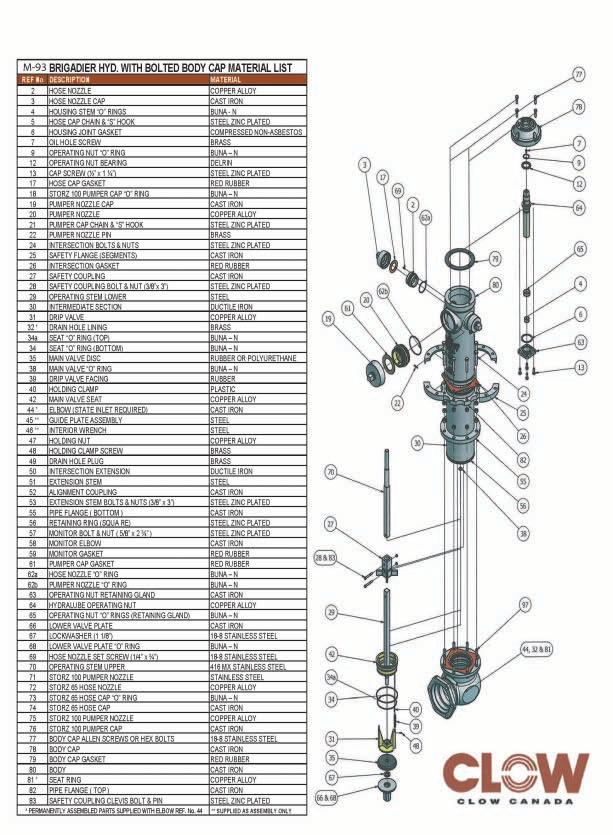
128

129
130 DESCRIPTION M&H POST TYPE HYDRANT Style 33 Style 133 Style 233 Style 333 Post type hydrants are special purpose hydrants for use where fire fighting is not the primary function. They are smaller in size than standard AWWA hydrants and are furnished with main valve opening diameter of 2 ½. They are most often used for wash down service at treatment plants. Other uses may be in water systems to flush, bleed air, or fill tank trucks in non-emergency service. Although the 2 ¼ post type model is not recognized by AWWA C502 standards for dry barrel fire hydrants, they are nonetheless manufactured to the same strict quality of materials and workmanship as full size M&H hydrants. Rated working pressure is 150 psi and each hydrant is hydrostatically tested to 300 psi. Available options for hose nozzles configurations: Style 33 Post hydrant has 1-2 ½ hose nozzle *Style 133 Post hydrant has 1-1 ½ hose nozzle *Style 233 Post hydrant has 2-1 ½ hose nozzles *Style 333 Post hydrant has 1-1 hose nozzle *Note: Consult factory for availability of custom hose nozzle sizes. Available options for shoe inlet connections: 2 or 3 Mechanical Joint 2, 2 ½, 3 Flanged Joint 2, 2 ½ Screwed joint September 2012 / M&H C502 / Post Type Hydrant
131
132 SUGGESTED SPECIFICATIONS (1 of 2) M&H 2 ¼ POST TYPE HYDRANT Style 33 Style 133 Style 233 GENERAL Post Type Hydrants shall comply, where applicable, with AWWA Standard C-502, latest revision. Post Hydrants shall be of the compression type, with the main valve opening against the pressure and closing with the pressure. The main valve opening shall be 2 1/4 diameter. Post Hydrants shall be of a dry barrel design. RATING Post Hydrants shall be rated at 250 psi water working pressure, tested at 500 pounds hydrostatic for structural soundness in the following manner; 300 pound hydrostatic test supplied from the inlet side, first with the main valve open for the testing of the drain valves and hydrant barrel. END Hydrants shall be connected to the main by a ((specify One) 2, 2 ¼, 3 ) mechanical joint, screwed or CONFIGURATION flange shoe. Mechanical joint shoes shall be fitted with strapping lugs. DESIGN Hydrants shall be constructed of ASTM A-126. The main valve facing of the hydrant shall be made of rubber. The bottom stem treads of the main valve rods shall be fitted with a bronze acorn nut, or suitable means, for sealing the threads away from the water. Hose nozzles shall be threaded and screwed into the nozzle section and then mechanically locked to prevent turning. Hose cap(s) shall be individually chained to the hydrant. The hydrant shall be so designed that when it is in place, no excavation will be required to remove the main valve assembly. The operating threads of the hydrant shall be so designed as to avoid the working of any iron or steel parts against either iron or steel. The operating stem and operating nut threads shall be square or acme type. Bonnet shall be weather proof, free draining, and of a type that will maintain the operating mechanism in readiness for use under freezing conditions. The operating nut shall be provided with a convenient means to afford lubrication to insure ease of operating and the prevention of wear and corrosion. Hydrants shall be of dry barrel type. Hydrant shoe shall have two positive acting non-corrodible drain valves that shall drain the hydrant completely by opening when the main valve is closed, and also to close tightly when the main valve is open. All like parts of hydrants of the same size and model produced by the same manufacturer shall be interchangeable. Hydrants shall open by turning to the (specify one (left or right)). September 2012 / M&H C502 / Post Type Hydrant
133 MH VALVE AWWA PRICE LIST EFFECTIVE DATE 2/10/2012 DESCRIPTION PART NO. LIST PRICE DESCRIPTION PART NO.LIST PRICE 1. Shoe - 2" M.J $ Operating Locknut - L.H $ Shoe - 3" M.J $ Operating Locknut - R.H $ Shoe - 2" Screwed $ Bonnet Bolt $ Standpipe - 2'0" Trench $ Bonnet Nut $8.00 Standpipe - 2'6" Trench $ Bonnet Gasket $13.00 Standpipe - 3'0" Trench $ Hose Nozzle - 2 1/2 NST $ Standpipe - 3'6" Trench $ Hose Nozzle - 1 1/2 NST $ Standpipe - 4'0" Trench $1, Hose Nozzle Set Screw $3.00 Standpipe - 4'6" Trench $1, Hose Nozzle Cap (inc. 16 & 17) $0.00 Standpipe - 5'0" Trench $1, /2" NST 1 1/2" PF $85.00 Standpipe - 5'6" Trench $1, /2" NST $85.00 Standpipe - 6'0" Trench $1, Hose Nozzle Cap Gasket $ Nozzle Section - 1-Way 2 1/ $ /2" NST $10.00 Nozzle Section - 2-Way 1 1/ $ /2" NST $10.00 Nozzle Section - 1-Way 1 1/ $ Hose Nozzle Cap Chain $ Bonnet - L.H $ * Standpipe Gasket $13.00 Bonnet - R.H $ * Standpipe Bolt $ Main Valve Rod (3/4" Dia.) - 3'0" T $ Standpipe Nut $8.00 Main Valve Rod (3/4" Dia.) - 3'0" T $ Drain Valve (inc. 26 & 27) $ Main Valve Rod (3/4" Dia.) - 3'6" T $ Main Valve Lower Plate $23.00 Main Valve Rod (3/4" Dia.) - 3'6" T $ Main Valve Rubber $70.00 Main Valve Rod (3/4" Dia.) - 4'0" T $ Main Valve Rod Acorn Nut $35.00 Main Valve Rod (3/4" Dia.) - 4'0" T $ Main Valve Seat $ Main Valve Rod (3/4" Dia.) - 4'6" T $ Main Valve Seat O-Ring $15.00 Main Valve Rod (3/4" Dia.) - 4'6" T $ Drain Valve Facing $13.00 Main Valve Rod (3/4" Dia.) - 5'0" T $ Drain Valve Rivet $3.00 Main Valve Rod (3/4" Dia.) - 5'0" T $ Stem Pin $5.00 Main Valve Rod (3/4" Dia.) - 5'6" T $ Hose Nozzle O-Ring $15.00 Main Valve Rod (3/4" Dia.) - 5'6" T $ Felt Washer NA (use oring) $8.00 Main Valve Rod (3/4" Dia.) - 6'0" T $ Weatherproof O-Ring $8.00 Main Valve Rod (3/4" Dia.) - 6'0" T $ Lubricating Plug $ Operating Nut - 1 1/2" P-F L.H $ Shoe Bolt $15.00 Operating Nut - 1 1/2" P-F R.H $ Shoe Nut $ Lub Screw $ Flanged Lug (Half) L $ Bonnet O-Ring $ Lower O-Ring Stem Seal $8.00 *Prior to 2012 Parts Listed Above. For 2012 and after see Below: 18. Standpipe O-Ring $ Standpipe Bolt $ /4" HYDRANT PARTS STYLE #0033, 0133,

134 PREMIER SERIES D-67-M

135 Drain valve tripod, valve seat and lower valve assembly Clow Canada is committed to the manufacture and delivery of superior products, supported by superior services. Strict quality control measures govern every step of the manufacturing process, to ensure precision and. consistency. We provide the knowledge, the technology and the products to serve industry's changing needs, efficiently and effectively. For more information about our products or services, please contact the Clow Canada sales office nearest you. External allen screw locks nozzle into place Clow Canada's Premier D-67-M incorporates several new design features and improved components for increased performance in firefighting, along with greater durability, economy and convenience. These hydrants are manufactured in Canada to the highest standards of quality every unit is thoroughly tested before leaving the Clow factory. Lubrication is assured through the Premier's unique Hydra-lube"" mechanism. The Premier can be rotated to any position - during or after installation - without disturbing the working mechanism. The rugged Premier D-67-M stands up to traffic-accident damage. It is designed for easy upkeep, repair and replacement of parts; its internal assembly can be removed and replaced in 20 minutes, without excavation. Alternative design options and accessories serve a wide range of municipal and industrial needs. The Premier's advantages include: efficient compression-type hydrant factory-lubricated operating mechanism effectively O-ring sealed for long and efficient operation very lovv opening and closing torques automatic drainage positive sealing vvith O-rings at operating nut, operating housing, seat, optional bronze casing and seat durable and positive seating easy multiple positioning safety stem coupling and safety flange internal parts easily removed - bury easily increased threaded hose and pumper nozzles - simple replacement if needed interchangeability vvith previous D-67-M model hydrants conforms to AWWA specifications Section through lubricating groove Hydra-lube'" operating nut

136 Hydra-lube The Premier's innovative Hydra-Iube T " system incorporates an internal grease channel for self-lubrication during operation. Stainless steel rod Stainless steel upper stem provides corrosion-free seating for O-rings. Nozzles An external allen screw mechanically locks nozzles into place; this offers greater assurance that nozzles will not turn or back out. Safety flange The Premier is equipped with a cast iron safety flange and grooved safety coupling. The safety flange is snap ring mounted onto a ductile iron intermediate section. If severe impact occurs, breakage will be at the safety flange and coupling. The hydrant body, working mechanism and intermediate section will remain undamaged. A...tomatlc drain To prevent corrosion and freeze-up. the hydrant body is automatically drained quickly through the drain tripod. Lower valve assembly The lower valve plate assembly is extended to fully encapsulate the lower rod threads. This allows for increased corrosion resistance and ease of disassembly. ~----,f tfo-epoxy coating A durable epoxy coating on the interior and exterior of the elbow guards against corrosion. OPEN CLOSED Listed by Underwriters' Laboratories of Canada. CLew CLOW CANADA Factory Mutual Approved

137 ti;l;;;~---rT-" t-<:I l Optional Storz connections ~ H l f ~---tt Ground line Optional brass to brass seat 4g55!lt~~ 46 )~45 /---23 /ooloitf+j+"' Dimensions shown In Inches unl_ othe'l'vi(l8!et I)oted DimensIOn X,Is 8.7,5" (222mm) less than bury required Parts 50 & 51 ate assembled together to form seat removal wrench Hydrant end joints 4" Flanged 8,50" Mechanical.Join-tlte DIMENSION 6" 8,50" 8,50" 8,75" A Flanged Mechanical.Join-tlte

138 NO. DESCRIPTION MATERIAL I 2 Bonnet operating nut O-ring Buna-N 3 Bonnet Cast iron ill 5 Operating nut bearing Delrin! ( 7 Bonnet gasket Red rubber I 62 9 Housing operating nut O-ring Buna-N 10 breaking coupling Cast iron i!i, ~ t~-+- ~64 11 Body 2 hose I pumper Cast iron 12 Hex. hd. bolt & nut Steel gr FM~ /11 13 Body gasket Fibre (non asbestos) 175 t- E 'ri c Hex. hd. bolt & nut Steel E D-67-M Itl "-.Jr Breaking flange Cast iron o CO PREMIER -I..I~ 17 Stem guide Cast iron ~ ~ Stem guide set screw Steel I CONCORD I 19 Intermediate section Ductile CANADA 20 Drain valve tripod Bronze 21 Drain valve screw 22 Drain valve rivet Copper II) 23 Drain valve rubber Gum rubber.. '" 150 P.S.1. ai 24 Gasket Red rubber 25 Upper O-ring Buna-N 26 Valve seat Bronze 26-1 Valve seat (optional) Bronze n+ I-+n 27 Lower O-ring Bu na-n I ' I 29 Valve carrier Cast iron '---'----- I!! I 30 Valve rubber Rubber '------r~ttn----n+rr----n"llf+n---j 1IIII _~3~1_+V~ailll~v~eE're::It<1alIinl<:e:t:r ~C~as~t~i~ro~n~ 1 Ground line 32 Base Cast iron 34 Bonnet allen screw Stainless steel 36 Hose cap gasket Red rubber 36-1 Pumper cap gasket Red rubber x 37-1 Pumper nozzle. Storz Stainless steel 37-2 Pumper nozzle. Storz Bronze 38-1 Pumper cap. Storz Cast iron 40 Hose nozzle chain & S-hook Steel 41 Pumper nozzle chain & S-hook Steel 43 Retaining ring Mild steel 44 Lower stem 1.25 sq. Steel 45 Drain hole lining Copper 46 Drain valve spring Stainless steel 47 Floating flange Cast iron 48 Threaded flange Cast iron 49 Spiral pin h.d. Stainless steel 50 Guide plate assembly Steel 51 Interior wrench Steel 52 Intersection extension Ductile 53 Monitor elbow Cast iron 54 Stud & nut Steel 55 Seat ring Bronze 56 Spiral pin Stainless steel 57 Extension coupling Cast iron 58 Ring gasket Fibre (non asbestos) 59 Operating nut Bronze 60 Operating nut retaining gland Cast iron 61 Operating stem upper Stainless steel 62 Hose nozzle Bronze 62-1 Pumper nozzle Bronze II).. l'i - T - 63 Hose cap Cast iron CLOW 63-1 Pumper cap Cast iron 64 Hose nozzle O-rino Buna-N 64-1 Pumper nozzle O-ring Buna-N 65 Gland operating nut O-ring Buna-N CLOW CANADA 66 Nozzle pin Brass 67 Hose nozzle set screw Stainless steel 68 P o B N PARTS LIST

139 1 Pumper, 2 Hose 1 Storz Pumper, 2 Hose Hydrant shall be manufactured in accordance with AWWA Standard C502, and shall be listed with ULC and FM. Hydrant shall be designed for 175 p.s.i. working pressure and tested to 350 p.s.i. hydrostatic pressure. Hydrant shall be backed by manufacturer's 5 year limited warranty. Hydrant shall be a compression type, dry barrel design with centre operating stem construction. The O-ring seating surface on the upper operating stem shall be constructed of stainless steel. Hydrant lower operating rod shall be J-l/4 inches in diameter. Hydrant shall have an internally lubricated bronze operating nut with O-ring seals. Operating nut shall be of the Hydra-Iube Tw design to ensure self-lubrication during operation. Hydrant hose nozzles shall be mechanically locked into place by an external allen screw, and have O-ring seals. Epoxy coating to be applied to interior and exterior of hydrant shoe for corrosion protection. Hydrant shall be manufactured with operating nut and integral thrust collar made of bronze. Delrin washer bearing shall be located above thrust collar for ease of hydrant operation. Hydrant shall have a lower valve assembly that fully encapsulates the lower operating rod threads. This allows for increased corrosion resistance and ease of disassembly. Hydrant shall have a main valve opening of 5 inches. Hydrant shall be a traffic model, complete with safety flange and stem coupling. Nozzle section must rotate 360 degrees. Intermediate section shall be ductile iron. Hydrant shall be the Clow Canada Premier as manufactured by Clow Canada.
 flanged outlet is faced and drilled to ANSI 125.")
140 Accessories/Alternatives/Options ( Monitor flange The Premier is available with monitor flange for use in industrial fire protection in pulp and paper mills. lumber yards or storage areas for inflammable matel'ials, The hydrant's 3" (76mm) flanged outlet is faced and drilled to ANSI 125. suitable for connecting a long radius flanged elbow and standpipe for mounting a monitor nozzle, M ConversIon kit Pl'evious 0-67 and 0-67-M models may be converted to incorporate important features of the Premier 0-67-M easily and without excavation by using the operating nut conversion kit. Kit consists of: two-piece stainless upper stem Hydl'a-Iube'" operating nut nut retainer gland and gasket Oelrin thrust bearing Specify 0-67 kit (I-IN' sq, stem) or 0-67-M kit (l-w' sq. stem). All Pl'emier 0-67-M components are interchangeable with pl'evious 0-67-M models, Safety flange Clow's Premier 0-67-M is equipped with a cast iron safety flange and grooved safety coupling. The safety flange is snap ring mounted onto a ductile il'on intermediate section. If severe impact occurs, breakage will be at the safety flange and coupling. The hydrant body, working mechanism and intel'mediate section will remain undamaged, Storz connectors The Premier is available with a complete line of integral 2-Yz" (65mm) and 4" (loomm) Storz quick connect couplings. The 2-Yz" coupling is bronze; the 4" is made type 316 stainless steel. Both come equipped with a cast iron cap. A complete line of retrofit stainless steel Storz couplings and adapters is available to convert existing 0-67 and 0-67-M hydrant models in most sizes, Some units are also available to retrofit different bl'ands of discontinued hydrants. ( Further details on Clow Canada's Premier 0-67-M, options and/or accessories are available upon request. CLew CLOW CANADA
141 ( HAMILTON, ONTARIO TOLL FREE NUMBER Tel. (905) Fax (905) SALES DESK CLew CLOW CANADA EASTERN CANADA Grandview Industrial Park P.D. Box 700 Saint John NB E2L 4B3 Tel. (506) Fax (506) WESTERN CANADA 801 Smelter Ave. S.E. P.O. Box 1000 Medicine Hat AB TIA 7Hl Tel. (403) Fax (403) HEAD OFFICE 600 Kenilworth Ave. N. P.D. Box 2849 Hamilton ON L8N 3R5 Tel. (905) Fax (905)
142 LISTEL) ~i>s88h <8> APPROVED Complies with applicable requirements of AVVVVA C509 n I I, I 8068A 2" -12" RlS VALVE FLANGE ENDS OS&YGENERAL DIMENSIONS KENNEDY VALVE MODEL KS-FW I------~H------t F (Open) E (Closed) STD. TAP SIZE 1/2": 2 112"-4", 3/4": 6" 12" G No. & Size Of Bolls "-Flanges ANSI CL 12: VALVE SIZE A B C D E F G H WEIGHT /2 6 11/ /8 7 1/4 N/A 21/2 71/2 3 3/4 7 11/16 137/8 163/8 4 5/8 71/ /2 3/4 155/8 187/8 45/ /2 9 15/ /4 223/4 8 5/ /2 51/ /4 301/8 8 3/ /2 5 3/4 131/2 1 1/8 291/4 373/4 83/ / /16 353/8 453/4 127/ /4 405/8 531/8 127/ ALL FLANGE VALVES TAPPED & POSITIQN "A" Kennedy Valve/KS-FW C
 ASTM B584 CDA 844 R-2 HAND WHEEL CAST IRON ASTM A126 CLASS B R-3 UPPER THRUST WASHER BRONZE ASTM B36 CDA 260 R-4 LOWER THRUST WASHER BRONZE --------")
143 ITEM DESCRIPTION MATERIAL ASTM SPEC. R-1 HAND WHEEL HOLD DOWN NUT BRONZE (AWWA GRADE A) ASTM B584 CDA 844 R-2 HAND WHEEL CAST IRON ASTM A126 CLASS B R-3 UPPER THRUST WASHER BRONZE ASTM B36 CDA 260 R-4 LOWER THRUST WASHER BRONZE R-5 YOKE NUT BRONZE ASTM B584 CDA 862 R-6 COVER/YOKE BOLTS & NUTS ZINC PLATED STEEL ASTM A307 GRADE B R-7 COVER/YOKE CAST IRON ASTM A126 CLASS B R-8 HEX HEAD PACKING GLAND BOLTS ZINC PLATED STEEL ASTM A307 GRADE B HEX HEAD PACKING GLAND BOLTS BRASS ASTM A563 R-9 PACKING GLAND DUCTILE IRON ASTM A R-10 PACKING BRAIDED LUBRICATED (NON-ASBESTOS) FIBER R-11 O-RING (COVER/YOKE) NBR R-12 O-RING (STEM) NBR R-13 STEM BRONZE ASTM B584/B21 R-14 STEM NUT BRONZE ASTM A584 CDA <-1::> WEDGE/GATE/DISK CAST IRON & SBR COATED ASTM A126 CL 8/D2000 I"<-lb BODY - ALL TYPES CAST IRON ASTM A126 CLASS B I"< 1 / PIPE PLUG GALVANIZED IRON R-4 R-5 R-7 ~R-8 R-6~ ---- R-9 R-11 R-13 l ~_r_- R-1 2 R-1 4 -~H-r~_r R-17 R-15 ~-16 I-D_W_N:_T_RIJ_--i 3" TH RU 12" KENNEDY VALVE ~ DATE: 7/1/05 RESILIENT SEAT GATE VALVE ELMIRA, NEW YORK lh), A DIVISION OF MCWANE INC ~ DWG. NO. VALVE ASSEMBLY / MATERIAL LIST C509-0S&Y-STYLE 8068 THIS DRAWING AND ALL INFORMATION IS OUR PROPERTY AND SHALL NOT BE USED. COPIED. OR REPROOUCED WITHOUT WRITTEN CONSDIT. DE:SIGN AND INVENTION RIGHTS RESEIMll.
144 C) OSYSU-1, -2 OUTSIDE SCREW AND YOKE VALVE SUPERVISORY SWITCH OSYSU-1 Stock No OSYSU-2 Stock No UL and CSFM Listed, FM Approved, NYMEA Accepted, CE Marked Dimensions: 6.19"L X 2.25"WX 5.88"H 15,7cm LX 5,7cm W X 14,6cm H Weight: 2lbs. (0,9 kg.) Enclosure: Cover - Die-Cast Finish - Red Spatter Enamel Base - Die Cast Zinc All parts have corrosion resistant finishes. Cover Tamper: Tamper resistant screws, Optional cover tamper kit available. Contact Ratings: OSYSU-1: One set of SPOT (Form C) OSYSU-2: Two sets of SPOT (Form C) Amps at 125/250VAC 2.50 Amps at 30VDC resistive Environmental Limitations: NEMA 4 and NEMA 6P Enclosure (IP67) when used with appropriate watertight conduit fittings. Indoor or Outdoor use (Not for use in hazardous locations. See bulletin no OSYS-U-EX for hazardous locations.) Temperature Range: -40 F to 140 F (-40 C to 60 C) Conduit Entrances: 2 knockouts for 1/2" conduit provided Service Use: Automatic Sprinkler NFPA-13 One or two family dwelling NFPA-13D Residential occupancy up to four stories NFPA-13R National Fire Alarm Code NFPA-72 o Potter GENERAL INFORMATION The OSYSU is used to monitor the open position of an OS & Y (outside screw and yoke) type gate valve. This device is available in two models; the OSYSU-1, containing one set of SPDT (Form C) contacts and the OSYSU-2, containing two sets of SPOT (Form C) contacts. These switches mount conveniently to most OS & Y valves ranging in size from 2" to 12" (50mm to 300mm). They will mount on some valves as small as 1/2" (12,5mm). The cover is held in place by two tamper resistant screws that require a special tool to remove. The tool is furnished with each device and should be left with the building owner or responsible party. Replacement or additional cover screws and hex keys are available. See ordering informa tion on page 4. OPTIONAL COVER TAMPER SWITCH A field installable cover tamper switch is available as an option which may be used to indicate removal of the cover. See ordering information on page 4. TESTING The OSYSU and its associated protective monitoring sys tem should be inspected and tested in accordance with applicable NFPA codes and standards and/or the authority having jurisdiction (manufacturer recommends quarterly or more frequently). Electric Signal Company 2081 Craig Road I St. Louis; MO Phone: /Canada PRINTED IN USA MKT. # REV P PAGE10F
145 OSYSU-1, -2 OUTSIDE SCREW AND YOKE VALVE e The Symbol of Protection SUPERVISORY SWITCH FIG. 1 SMALL VALVE INSTALLATION.1/2" THRU 21/2" (12,5mm THRU 63,5mm) SIZES THESE SWITCHES MOUNT CONVENIENTLY TO MOST 2 11 TO OS & Y VALVES. THEY WILL MOUNT ON SOME VALVES AS SMALL AS 1/2 11 (12,5MM). J-HOOKS MAY BE REQUIRED ON VALVES WITH LIMITED CLEARANCE. SLOTTED MOUNTING HOLES MAY BE USED FOR FINE ADJUSTMENT OF SWITCH ON BRACKET CLAMP BAR BRACKET CARRIAGE BOLT C) DWG. #979-3 SMALL VALVE INSTALLATION 1. Remove and discard "c" washer and roller from the trip rod. 2. With the valve in the FULL OPEN position, locate the OSYSU across the valve yoke as far as possible from the valve gland, so that the trip rod lays against the nonthreaded portion of the valve stem. 3. Loosen the locking screw that holds the trip rod in place and adjust the rod length (see Fig. 4). When adjusted properly, the rod should extend past the valve screw, but not so far that it contacts the clamp bar. Tighten the locking screw to hold the trip rod in place. NOTE: If trip rod length is excessive, loosen the locking screw and remove the trip rod from the trip lever. Using pliers, break off the 1" (25mm) long notched section (see Fig. 5). Reinstall trip rod and repeat Step 3 procedure. 4. Mount the OSYSU loosely with the carriage bolts and clamp bar supplied. On valves with limited clearance use..i-hooks supplied instead of the carriage bolts and clamp bar to mount the OSYSU. 5. Mark the valve stem at the center of the trip rod. 6. Remove the OSYSU. File a 1/8" (3,2mm) deep groove centered on the mark on the valve stem utilizing a 3/16" (4,8mm) round, non-tapered file. Round and smooth the edges of the groove to prevent damage to the valve packing and to allow the trip rod to move easily in and out of the groove as the valve is operated. 7. Mount the OSYSU with the trip rod centered in groove. 8. Final adjustment is made by loosening 2 screws (see Fig. 1) and sliding the OSYSU on the bracket. Adjustment is correct when switches are not activated with the trip rod seated in the valve stem groove and that the switches activate when the trip rod moves out of the groove. 9. Tighten the adjustment screws and all mounting hardware. Check to insure that the rod moves out of the groove easily and that the switches activate within one turn when the valve is operated from the FULL OPEN towards the CLOSED position. NOTE: CLOSE THE VALVE FULLY TO DETERMINE THAT THE STEM THREADS DO NOT ACTIVATE THE SWITCH. THE SWITCH BEING ACTIVATED BY THE STEM THREADS COULD RESULT IN A FALSE VALVE OPEN INDICATION. PRINTED IN USA MKT. # REV P PAGE 2 OF
146 ('.."\ ~_) POTTER The Symbol of Protection OSYSU-1, -2 OUTSIDE SCREW AND YOKE VALVE SUPERVISORY SWITCH FIG. 2 LARGE VALVE INSTALLATION - 3" THRU 12" (76mm THRU 300mm) SIZES 3" THRU 12" (76mm THRU 300mm) VALVES USE CARRIAGE BOLTS. BOLTS MOUNT ON INSIDE OF YOKE, IF THERE IS SUFFICIENT CLEARANCE. CLAMP BAR CARRIAGE BOLTS (2 REQUIRED) SLOTTED MOUNTING HOLES. MAY BE USED ROLLER FOR FINE ADJUSTMENT GROOVE OF SWITCH ON BRACKET. YOKE VALVE STEM TRIP ROD DWG. #979-4 LARGE VALVE INSTALLATION 1. With the valve in the FULL OPEN position, locate the OSYSU across the valve yoke as far as possible from the valve gland, so that the trip rod lays against the nonthreaded portion of the valve stem. 2. Mount the OSYSU loosely with the carriage bolts and clamp bar supplied. 3. Loosen the locking screw that holds the trip rod in place and adjust the rod length (see Fig. 4). When adjusted properly, the rod should extend past the valve screw, but not so far that it contacts the clamp bar. Tighten the locking screw to hold the trip rod in place. \, NOTE: If trip rod length is excessive, loosen the locking screw and remove the trip rod from the trip lever. Using pliers, break off the one 1" (25mm) long notched section (see Fig. 5). Reinstall trip rod and repeat Step 3 procedure. 4. Mark the valve stem at the center of the trip rod. 5. Remove the OSYSU. File a 1/8" (3,2mm) deep groove centered on the mark of the valve stem utilizing a 3/8" (9,5mm) round, non-tapered file. Round and smooth the edges of the groove to prevent damage to the valve packing and to allow the trip rod to move easily in and out of the groove as the valve is operated. 6. Mount the OSYSU loosely with the trip rod centered in groove. 7. Final adjustment is made by loosening 2 screws (see Fig. 2) and sliding the OSYSU on the bracket. Adjustment is correct when switches are not activated with the trip rod seated in the valve stem groove and that the switches activate within one tum when the valve is operated from the FULL OPEN towards the CLOSED position. 8. Tighten the adjustment screws and mounting hardware. Check to insure that the rod moves out of the groove easily and that the switches activate within one tum when the valve is operated from the FU LL OPEN towards the CLOSED position. NOTE: CLOSE THE VALVE FULLY TO DETERMINE THAT THE STEM THREADS DO NOT ACTIVATE THE SWITCH. THE SWITCH BEING ACTIVATED BY THE STEM THREADS COULD RESULT IN A FALSE VALVE OPEN INDICATION. PRINTED IN USA MKT. # REV P PAGE30F
147 OSYSU-1, -2 OUTSIDE SCREW AND YOKE VALVE SUPERVISORY SWITCH FIG. 3 DIMENSIONS FIG. 4 PARTS KNOCKOUIS FOR ELECTllICAL CONNECTIONS BREAKING EXCESSIVE ROD LENGTH FIG.S SWITCH TERMINAL CONNECTIONS CLAMPING PLATE TERMINAL TYPICAL ELECTRICAL CONNECTIONS LOCAL CIRCUIT TO POWER FOR INDICATING DEVICE INDICATING DEVICE o For ORDERING INFORMATION CAUTION: An uninsulated section of a single conductor should not be looped around the terminal and serve as two separate connections. The wire must be severed, thereby providing supervision ofthe connection in the eventthat the wire becomes dislodged from under the terminal. MODEL DESCRIPTION STOCK NO. OSYSU-1 Outside Screw & Yoke-Supervisory Switch (Single switch) OSYSU-2 Outside Screw & Yoke-Supervisory Switch (Double switch) Cover Screw Hex Key for Cover Screws and Installation Adjustments Optional Cover Tamper Switch Kit pressure reducer type valve installation kits (if required) contact yalve ma~~facturer. TO SUPERVISORY CIRCUIT OF CONTROL PANEL Contacts shown in normal (valve open) condition. TYPICAL SWITCH ACTION OPEN VI>LVE POSITION COM. ~ SWll~ N.C, I I COM.I~ SW 12~"'" n..,. ~ DWG. CLOSED VALVE POSITION C~O' N.O. SWll It=- I C~M.~ SW '2 r.j~liir_ t=- #979-2 END OF LINE RESISTOR DWG PRINTED IN USA MKT. # REV P PAGE 4 OF
148 TTS TANK TEMPERATURE SUPERVISORY SWITCH TTS-S The Model TTS is a water tank temperature supervisory switch preset to give a low temperature signal at 40 F/4,5 C and a high temperature signal at 140 F/60 C (±5 F/3 C). It is UL Listed and FM Approved. A bi-metal thermostat is used for low temperature sensing and a bi-metal thermostat for high temperature sensing. A diode is used in this unit as a testing aid. When the polarity of DC current is reversed at the feed wires to a TTS, the diode in the circuit prevents the flow of current, proving the absence of a short circuit fault in the wiring or the device itself. Testing To test for a short or open in the TTS, connect an ohmmeter across the white and black TTS leads. With the meter connected positive to white and negative to black, the meter will read continuity (about 1 meg ohm). With the meter connected reverse polarity, the meter will read open. If using the diode tester setting on the meter, the meter will read.5 observing polarity and open with reverse polarity. To test the thermostat, the device must be exposed to temperatures of 40 F and 140 F. The appropriate thermostat will open creating an open circuit regardless of polarity. Wiring The TTS is normally closed device that opens when the probe is exposed to the operating temperature of the thermostats. The device is polarity sensitive. The positive leg of the initiating device circuit must CUL, UL and CSFM Listed, FM Approved, and NYMEA Accepted 2 1/2" DIA x 17 1/2"L (63,5mm DIA x 445mm L) Ordering Information Model Number Stock Number TTS-S (steel) TTS-W (wood) Accessories 1" Flange Buttress Nut Gasket be connected to the white wire lead. The negative leg of the initiating device circuit must be connected to the black wire lead. If the TTS is the last or only device on the initiating circuit, the EOLR must be wired in series with the TTS. It can be wired in series with either the black or white wire. Contacts:.15 Amp at 115 VDC The TTS, tank temperature switch is supplied with a one inch pipe thread for steel tanks (Model TTS-S) or with a buttress thread for wood tanks (Model TTS-W). A buttress thread nut and gasket are available for use with the TTS-W for installations where the inside of the tank is accessible and it is not convenient to weld a flange on the tank. The nut and gasket can also be used on a wood tank, which is not sound enough to hold a thread (see Fig. 1). Locate the switch at a point 24" (60cm) below the required water level of the tank. For steel tanks, weld in a No pipe flange or drill and tap tank to receive the one inch pipe thread of the bushing (see Fig. 2). For wood tanks, drill a 1 3/16" (30mm) hole in the center of a stave and thread the bushing into the tank allowing the buttress bushing to cut its own thread (see Fig. 3). Installation Fig. 1 TTS-W (Wood or Steel) 1-3/8 (35mm) HOLE WOOD OR STEEL TANK WALL Fig. 2 TTS-S (Steel) TANK WALL NUT GASKET 1 (25mm) STANDARD PIPE THREAD 1 (25mm) PIPE FLANGE #282-1 BUTTRESS THREAD DWG# CONDUIT OPENING 1/2 DWG# WELDED FLANGE CONDUIT OPENING 1/2 Potter Electric Signal Company 2081 Craig Road, St. Louis, MO, Phone: /Canada PRINTED IN USA MKT. # REV L MFG. # /07 PAGE 1 OF 2
149 TTS TANK TEMPERATURE SUPERVISORY SWITCH Fig. 3 TTS-W (Wood) Fig. 4 TTS-S Simplified Schematic WOOD TANK WALL WHITE LEAD 40 THERMOSTAT NORMALLY CLOSED BUTTRESS THREAD DIODE CONDUIT OPENING 1/2 BLACK LEAD 140 THERMOSTAT NORMALLY CLOSED DWG# DWG# Important: Observe lead polarity for use in normally closed circuit. WHITE LEAD EOLR 40 THERMOSTAT NORMALLY CLOSED DIODE BLACK LEAD 140 THERMOSTAT NORMALLY CLOSED DWG# Important: Observe lead polarity for use in normally open circuit. PRINTED IN USA MKT. # REV L MFG. # /07 PAGE 2 OF 2
150 OSYSU 1, 2 OUTSIDE SCREW AND YOKE VALVE SUPERVISORY SWITCH UL, ULC, and CSFM Listed, FM Approved, NYMEA Accepted, CE Marked Dimensions: 6.19"L X 2.25"W X 5.88"H 15,7cm L X 5,7cm W X 14,6cm H Weight: 2 lbs. (0,9 kg.) Enclosure: Cover Die Cast Finish Red Spatter Enamel Base Die Cast Zinc All parts have corrosion resistant finishes. Cover Tamper: Tamper resistant screws, Optional cover tamper kit available. Contact Ratings: OSYSU 1: One set of SPDT (Form C) OSYSU 2: Two sets of SPDT (Form C) Amps at 125/250VAC 2.50 Amps at 30VDC resistive Environmental Limitations: NEMA 4 and NEMA 6P Enclosure (IP67) when used with appropriate watertight conduit fittings. Indoor or Outdoor use (Not for use in hazardous locations. See bulletin no OSYS U EX for hazardous locations.) Temperature Range: 40 F to 140 F ( 40 C to 60 C) Conduit Entrances: 2 knockouts for 1/2" conduit provided Service Use: Automatic Sprinkler One or two family dwelling Residential occupancy up to four stories National Fire Alarm Code NFPA 13 NFPA 13D NFPA 13R NFPA 72 General Information The OSYSU is used to monitor the open position of an OS&Y (outside screw and yoke) type gate valve. This device is available in two models; the OSYSU 1, containing one set of SPDT (Form C) contacts and the OSYSU 2, containing two sets of SPDT (Form C) contacts. These switches mount conveniently to most OS&Y valves ranging in size from 2" to 12" (50mm to 300mm). They will mount on some valves as small as ½" (12,5mm). The cover is held in place by two tamper resistant screws that require a special tool to remove. The tool is furnished with each device and should be left with the building owner or responsible party. Replacement or additional cover screws and hex keys are available. See Ordering Information. Optional Cover Tamper Switch A field installable cover tamper switch is available as an option which may be used to indicate removal of the cover. See Ordering Information. Testing The OSYSU and its associated protective monitoring system should be inspected and tested in accordance with applicable NFPA codes and standards and/or the authority having jurisdiction (manufacturer recommends quarterly or more frequently). Ordering Information Model Description Stock No. OSYSU 1 Outside Screw & Yoke Supervisory Switch (Single switch) OSYSU 2 Outside Screw & Yoke Supervisory Switch (Double switch) Cover Screw Hex Key for Cover Screws and Installation Adjustments Optional Cover Tamper Switch Kit For pressure reducer type valve installation kits (if required) contact valve manufacturer. Potter Electric Signal Company, LLC 2081 Craig Road, St. Louis, MO, Phone: /Canada PRINTED IN USA MKT. # REV R MFG# /08 PAGE 1 OF 3
151 OSYSU 1, 2 OUTSIDE SCREW AND YOKE VALVE SUPERVISORY SWITCH Fig. 1 Small Valve Installation ½" thru 2½" (12,5mm thru 63,5mm) Sizes Fig. 2 Large Valve Installation 3" thru 12" (76mm thru 300mm) Sizes These switches mount conveniently to most 2" to 12" OS&Y valves. They will mount on some valves as small as ½" (12,5mm). J hooks may be required on valves with limited clearance. Small Valve Installation 1. Remove and discard "C" washer and roller from the trip rod. 2. With the valve in the FULL OPEN position, locate the OSYSU across the valve yoke as far as possible from the valve gland, so that the trip rod lays against the non threaded portion of the valve stem. 3. Loosen the locking screw that holds the trip rod in place and adjust the rod length (see Fig. 4). When adjusted properly, the rod should extend past the valve screw, but not so far that it contacts the clamp bar. Tighten the locking screw to hold the trip rod in place. Note: If trip rod length is excessive, loosen the locking screw and remove the trip rod from the trip lever. Using pliers, break off the 1" (25mm) long notched section (see Fig. 5). Reinstall trip rod and repeat Step 3 procedure. 4. Mount the OSYSU loosely with the carriage bolts and clamp bar supplied. On valves with limited clearance use J hooks supplied instead of the carriage bolts and clamp bar to mount the OSYSU. 5. Mark the valve stem at the center of the trip rod. 6. Remove the OSYSU. File a 1/8" (3,2mm) deep groove centered on the mark on the valve stem utilizing a 3/16" (4,8mm) round, non tapered file. Round and smooth the edges of the groove to prevent damage to the valve packing and to allow the trip rod to move easily in and out of the groove as the valve is operated. 7. Mount the OSYSU with the trip rod centered in groove. 8. Final adjustment is made by loosening 2 screws (see Fig. 1) and sliding the OSYSU on the bracket. Adjustment is correct when switches are not activated with the trip rod seated in the valve stem groove and that the switches activate when the trip rod moves out of the groove. 9. Tighten the adjustment screws and all mounting hardware. Check to insure that the rod moves out of the groove easily and that the switches activate within one turn when the valve is operated from the FULL OPEN towards the CLOSED position. Note: Close the valve fully to determine that the stem threads do not activate the switch. The switch being activated by the stem threads could result in a false valve open indication. Large Valve Installation 1. With the valve in the FULL OPEN position, locate the OSYSU across the valve yoke as far as possible from the valve gland, so that the trip rod lays against the non threaded portion of the valve stem. 2. Mount the OSYSU loosely with the carriage bolts and clamp bar supplied. 3. Loosen the locking screw that holds the trip rod in place and adjust the rod length (see Fig. 4). When adjusted properly, the rod should extend past the valve screw, but not so far that it contacts the clamp bar. Tighten the locking screw to hold the trip rod in place. Note: If trip rod length is excessive, loosen the locking screw and remove the trip rod from the trip lever. Using pliers, break off the one 1" (25mm) long notched section (see Fig. 5). Reinstall trip rod and repeat Step 3 procedure. 4. Mark the valve stem at the center of the trip rod. 5. Remove the OSYSU. File a 1/8" (3,2mm) deep groove centered on the mark of the valve stem utilizing a 3/8" (9,5mm) round, non tapered file. Round and smooth the edges of the groove to prevent damage to the valve packing and to allow the trip rod to move easily in and out of the groove as the valve is operated. 6. Mount the OSYSU loosely with the trip rod centered in groove. 7. Final adjustment is made by loosening 2 screws (see Fig. 2) and sliding the OSYSU on the bracket. Adjustment is correct when switches are not activated with the trip rod seated in the valve stem groove and that the switches activate within one turn when the valve is operated from the FULL OPEN towards the CLOSED position. 8. Tighten the adjustment screws and mounting hardware. Check to insure that the rod moves out of the groove easily and that the switches activate within one turn when the valve is operated from the FULL OPEN towards the CLOSED position. Note: close the valve fully to determine that the stem threads do not activate the switch. The switch being activated by the stem threads could result in a false valve open indication. PRINTED IN USA MKT. # REV R MFG# /08 PAGE 2 OF 3
152 OSYSU 1, 2 OUTSIDE SCREW AND YOKE VALVE SUPERVISORY SWITCH Fig. 3 Dimensions Fig. 4 Parts Fig. 5 Breaking Excessive Rod Length Typical Electrical Connections Switch Terminal Connections Clamping Plate Terminal Contacts shown in normal (valve open) condition. Typical Switch Action An uninsulated section of a single conductor should not be looped around the terminal and serve as two separate connections. The wire must be severed, thereby providing supervision of the connection in the event that the wire becomes dislodged from under the terminal. PRINTED IN USA MKT. # REV R MFG# /08 PAGE 3 OF 3

153 PCVS-1, -2 CONTROL VALVE SUPERVISORY SWITCH Conduit Entrances: Two knockouts for 1/2" conduit provided. Service Use: Automatic Sprinkler NFPA-13 One or two family dwelling NFPA-13D Residential occupancy up to four stories NFPA-13R National Fire Alarm Code NFPA-72 The Model PCVS is a weather proof and tamper resistant switch for monitoring the open position of fire sprinkler control valves of the post indicator, butterfly and other types. Depending on the model, one or two SPDT (Form C) contacts are provided which will operate when the valve position is altered from an open state. The unit mounts in a 1/2" NPT tapped hole in the post indicator or butterfly valve housing. The device is engaged by the indicating assembly of the post indicator or the operating mechanism of the butterfly valve, actuating switch(es) when the valve is fully open. The unit should be installed where it is accessible for service. The cover is held in place by two tamper resistant screws that require a special tool to remove. The tool is furnished with each device and UL, ULC, and CSFM Listed, FM Approved, NYMEA Accepted, CE Marked Dimensions: 4.75"L x 2.25"W x 8.2"H (stem extended) 12,1cm L x 5,7cm W x 18,3cm H Weight: 1.35 lb. (0,61 kg.) Enclosure: Cover - Die-cast Finish - Red Spatter Enamel Base - Die Cast Zinc All parts have corrosion resistant finishes. Cover Tamper: Tamper Resistant Screws, Optional cover tamper kit available Mounting: 1/2" NPT Contact Rating: PCVS-1: One set of SPDT (Form C) PCVS-2: Two sets of SPDT (Form C) Amps at 125/250VAC 2.50 Amps at 30VDC resistive Environmental Limitations: -40 F to +140 F (-40 C to 60 C) NEMA 4 and NEMA 6P Enclosure (IP67) when used with appropriate watertight conduit fittings. Indoor or Outdoor Use (Not for use in hazardous locations. See bulletin no PIVS-U-EX for hazardous locations.) should be left with the building owner or responsible party. Replacement or additional cover screws and hex keys are available. See ordering information. Optional Cover Tamper Switch A field installable cover tamper switch is available as an option which may be used to indicate removal of the cover. See ordering information. Testing The PCVS and its associated protective monitoring system should be tested in accordance with applicable NFPA codes and standards and/or the authority having jurisdiction (manufacturer recommends quarterly or more frequently). Ordering Information Model Description Stock No. PCVS-1 Potter Control Valve Switch (single switch) PCVS-2 Potter Control Valve Switch (double switch) Cover Screw Hex Key for Cover Screws and Installation Adjustments PBK-S Pratt Butterfly Valve Kit - Up to 12" (300mm) PBK-L Pratt Butterfly Valve Kit - 14" (355mm) and Up PVK Pratt Valve Kit Optional Cover Tamper Switch Kit KBK Kennedy Butterfly Valve Kit For pressure reducer type valve installation kits (if required) contact valve manufacturer. Potter Electric Signal Company 2081 Craig Road, St. Louis, MO, Phone: /Canada PRINTED IN USA MKT. # REV U MFG. # /07 PAGE 1 OF 4
154 PCVS-1, -2 CONTROL VALVE SUPERVISORY SWITCH Fig. 1 Dimensions Fig. 2 Parts 4.75 (12,1cm) 3.62 (9,2cm) 2.25 (5,7cm) 2,00 (12,1cm) 8.20 (20,8cm) 5.20 (13,2cm) 3.00 (7,6cm).75 (1,9cm).85 (2,2cm) 1.20 ROD RETRACTED AND (3,0cm).12 BREAKAWAY SECTION (0,30cm) REMOVED ROD EXTENDED 3.12 (7,9cm) 1.12 (2.8cm).85 (2,2cm) 1.56 (4,0cm) (WHITE) COM. (RED) N.O. BLACK N.C. KNOCKOUTS FOR ELECTRICAL CONNECTIONS DWG# TRIP ROD LOCKING SCREW SOCKET HEAD SCREW NIPPLE LOCKNUT TRIP ROD GROUND SCREW DWG# Typical Installations On Post Indicator Valve Housings (See Figs. 3 Thru 6) Refer to Fig. 2 for the location of parts described in the following instructions. Note: If the sprinkler system is in service the owner or authorized representative should be notified, before any work is done on the system, that the valve controlling the water supply to the system may be closed for periods of time during the installation and testing of this device, resulting in all or portions of the system being inoperative during these periods. If the system is not in service and valve is closed, be sure that opening the valve will not allow any unwanted water flow due to openings in the system, such as heads off, broken or incomplete piping, etc. 1. Position the valve to fully open ( OPEN should appear in the window of the housing). Partially close the valve while observing the direction that the target assembly moves. Reopen the valve. If the valve housing is predrilled with a 1/2" NPT for installation of a monitoring switch, remove the 1/2" plug and fully open the valve. Make sure that OPEN appears in the window of the housing. GO TO STEP NO Remove the head and target assembly (consultation with valve manufacturer is recommended). 3. If the target assembly moved up as the valve was closed, measure the distance from the bottom of the head to the lower part of the target assembly that will contact the trip rod of the PCVS (see Fig. 3). This is usually a plate or bar on the target assembly, on a side adjacent to the OPEN/SHUT plates. Subtract 1/8" from the measurement. If the target moved down as the valve was closed, measure the distance from the bottom of the head to the upper portion of the target assembly that will contact the trip rod of the PCVS (see Fig. 4). Add 1/8" (3,2mm) to this measurement. 4. Mark the housing at the proper location. Using a 23/32" (18,2mm) drill bit, drill and then tap a 1/2" NPT in the housing on the side that coincides with the portion of the target assembly that will engage the trip rod of the PCVS. 5. Replace the head and target assembly. 6. Loosen the socket head screw that holds the nipple in the PCVS and remove the nipple. 7. Screw the locknut that is provided onto the nipple. 8. Screw the nipple into the 1/2" NPT hole in the valve housing - hand tighten. Tighten the locknut against the valve housing to secure the nipple firmly in place. 9. Insert a scale or probe thru the nipple to measure the distance from the open end of the nipple to the target assembly. Subtract 1/2" (12,5mm) from this measurement. NOTE: In some cases, it may be necessary to attach an angle bracket to the target assembly to engage the PCVS trip rod. 10. Using the special tool provided, loosen the two cover screws and remove the cover from the PCVS. 11. Loosen the locking screw that holds the trip rod in place and adjust the rod length, from the end of the collar to the end of the rod, using the dimension determined in Step 9. Tighten the locking screw to hold the rod in place. NOTE: If trip rod length is excessive, loosen the locking screw and remove the trip rod from the trip lever. Using pliers, break off the one (1) inch long notched section (see Fig. 7). Reinstall trip rod and repeat Step 11 procedure. 12. Partially close the valve (3 to 4 revolutions of the handle/hand wheel). 13. Slide the PCVS unit as far as possible onto the nipple, observing which direction the rod will move when the valve is closed. Orient the device to actuate the switches when the valve is open. Tighten the socket head screw in the collar. 14. Carefully open the valve to the fully open position. As the target moves to the open position it should engage the trip rod and actuate the switch(es). There should be a minimum overtravel of 1/2 revolution of the handle/ hand wheel after the switch(es) actuate (a continuity meter connected to each set of contacts is one method that could be used to determine this). 15. Slowly close the valve. The switch must operate during the first two revolutions of the handle/hand wheel or during 1/5 of the travel distance of the valve control apparatus from its normal condition. NOTE: Small adjustments of the target position may be necessary (consultation with valve manufacturer is recommended). 16. Complete the required electrical wiring, connections and tests. The valve should be operated through the entire cycle of fully closed and fully open to determine the integrity of the PCVS installation and the signaling system. Check that all electrical and mechanical connections are secure. 17. When the installation and testing are complete, return valve to its proper position. 18. Alternative installation for other post indicator valve housing shown in Fig. 5 and 6. PRINTED IN USA MKT. # REV U MFG. # /07 PAGE 2 OF 4
155 Fig. 3 Fig. 4 Fig. 5 Fig. 6 PCVS-1, -2 CONTROL VALVE SUPERVISORY SWITCH OPEN UT TARGET MOVES UP AS VALVE IS SHUT TAMPER SWITCH UT OPEN TAMPER SWITCH TARGET MOVES DOWN AS VALVE IS SHUT STEEL TRIPPING BLOCK - REPLACES OPEN MARKER SHUT MARKER METAL PLATE REPLACES GLASS TARGET ASSEMBLY LOCKNUT TAMPER SWITCH FLEXIBLE CONDUIT 11 3/8 (28,9cm) TARGET MOVES UP AS VALVE IS SHUT HOOD MOVES DOWN AS VALVE IS SHUT DWG# Notes: 1. Subject to the approval of the authority having jurisdiction the alternate method of installation shown in Fig. 5 may be used. In this method, one of the glass windows of the housing is replaced with a 1/4" thick metal plate that is cut to fit in place of the glass and drilled and tapped to receive the 1/2" NPT pipe nipple. In some cases it may be necessary to attach an angle bracket to the target assembly to engage the PCVS trip rod. Typical Installation On A Butterfly Valve (See Figs. 9 And 10) Refer to Fig. 2 for location of parts described in the following instructions: B1. Remove the 1/2" NPT plug from the gear operator case. B2. Loosen the set screw that holds the nipple in the PCVS and remove the nipple. B3. Screw the locknut that is provided onto the nipple. B4. Screw the nipple into the 1/2" NPT hole in the gear operator - hand tighten. Tighten the locknut against the case, to secure the nipple firmly in place. B5. Partially close the valve (3 or 4 revolutions of the hand wheel or crank). B6. Using the special tool provided, loosen the two cover screws and remove the cover from the PCVS. B7. Loosen the locking screw that holds the trip rod in place. Estimate trip rod length required and extend slightly past that point. Slide the PCVS unit as far as possible onto the nipple, observing which direction the rod will move when the valve is closed. Orient the device to actuate switches when valve is open. Note: If trip rod length is excessive, loosen the locking screw and remove the trip rod from the trip lever. Using pliers, break off the one (1) inch long notched section (see Fig. 7). Reinstall trip rod and repeat Step B7 procedure. 2. If the target is stationary and a hood arrangement is used, such as is shown in Fig. 6, the hood must be drilled with a 23/32" drill and tapped with a 1/2" NPT. The center line of this hole should be 1/8" below the portion of target assembly that strikes the PCVS trip rod. The 11 3/8" dimension shown is for a Clow Valve. Flexible conduit must be used for this type of installation. B8. Remove device from nipple and withdraw trip rod 1/32" (0,80mm) (this dimension is important). Tighten the locking screw to hold the rod in place. Re-install the device on the nipple. Tighten the screw in the collar against the nipple. Note: In some cases it may be necessary to remove the gear box cover to ensure correct operation (consultation with the valve manufacturer is recommended). B9. Carefully open the valve to its full open position, as the boss on the gear hub moves to the open position it must engage the PCVS trip rod and actuate the switch(es). There should be a minimum overtravel or revolution of the crank or hand wheel after the switch(es) actuate (a continuity meter connected to each set of contacts is one method that could be used to determine this). Note: Slight adjustment of gear stops may be necessary to prevent overtravel of the trip rod (consultation with valve manufacture is recommended). B10. Carefully close the valve. The switch(es) must operate during the first two revolutions of the crank or hand wheel or during 1/5 of the travel distance of the valve control apparatus from its normal condition. B11. Complete the required electrical wiring, connections and tests. The valve should be operated through the entire cycle of fully closed and fully open to determine the integrity of the PCVS installation Fig. 7 Breaking Excessive Rod Length Fig. 8 Switch Terminal Connections Clamping Plate Terminal DWG# DWG# OUTGOING INCOMING An uninsulated section of a single conductor should not be looped around the terminal and serve as two separate connections. The wire must be severed, thereby providing supervision of the connection in the event that the wire becomes dislodged from under the terminal. PRINTED IN USA MKT. # REV U MFG. # /07 PAGE 3 OF 4
156 PCVS-1, -2 CONTROL VALVE SUPERVISORY SWITCH ITT Grinnell/Kennedy Indicating Butterfly Valve Fig. 9 Dresser Indicating Butterfly Valve Fig. 10 Typical Pressure Reducer Type Valve Installation Fig. 11 COLLAR LOCKNUT NIPPLE PCVS 1/32 (0,8mm) 1/16 (1,6mm) MIN. GAP DWG# VALVE PARTIALLY CLOSED VALVE OPEN DWG# /2 (13mm) DWG# This figure shows the Model PCVS mounted on the valve yoke, with a bracket supplied by the valve manufacturer, to supervise a pressure reducer type valve. Note: This application is subject to the approval of the authority having jurisdiction. PBK - Pratt IBV Butterfly Valve Kit Fig. 12 PVK - Pratt PIVA Post Indicator Valve Kit (Stock No ) Fig. 13 Typical Electrical Connections Please Note: This device should be wired in accordance with the applicable parts of the National Electrical Code, all state and local codes, applicable NFPA Standards and the requirements of the authority having jurisdiction. Fig. 14 LOCKNUTS BOTH SIDES LOCAL CIRCUIT N.O. MACHINE SCREW #8-32 COM. TO POWER FOR INDICATING DEVICE N.C. INDICATING DEVICE BRACKE AND LOCHNU SUPPLIE WITH PB MOUNTI KIT TO SUPERVISORY CIRCUIT OF CONTROL PANEL COM. N.O. N.C. END OF LINE RESISTOR Contacts shown in normal (valve open) condition. Model PBK-L Stock No (MDT-4S Actuator) Model PBK-M Stock No (MDT-3S Actuator) Model PBK-S Stock No (MDT-2S Actuator) Pratt Butterfly Valve Kit as used to mount a PCVS on a Pratt Model IBV Valve. Kits contain: Bracket, nuts and instructions Note: This application is subject to the approval of the authority having jurisdiction. DWG# Pratt Valve Kit as used to mount a PCVS on a Pratt Model PIVA Valve. Kit contains: Instructions, template, screw and nut. Note: This application is subject to the approval of the authority having jurisdiction. Typical Switch Action OPEN VALVE POSITION CLOSED VALVE POSITION COM. N.O. SW #1 COM. N.O. SW #1 N.C. N.C. COM. N.O. N.O. SW #2 SW #2 N.C. N.C. DWG# Switches Shown in Valve Open Position PRINTED IN USA MKT. # REV U MFG. # /07 PAGE 4 OF 4
 General The Model RBVS is designed to monitor the fully open position of a ball valve installed in a sprinkler system.")
157 RBVS UNIVERSAL BALL VALVE SWITCH US Patent No. 6,945,509 RBVS Stock No (w/o Cover Tamper) RBVS-T Stock No (w/cover Tamper) General The Model RBVS is designed to monitor the fully open position of a ball valve installed in a sprinkler system. The unit will fit on most ball valves installed on back-flow-preventers and alarm trim lines of dry, alarm, and deluge sprinkler valves. The switch operates if the ball valve handle is moved from the open position. However, the switch does not track the position of the handle or ball. When the ball valve handle is in the open position, a spring-loaded switch button will contact the valve handle. When the handle is moved from the open position, this switch button extends to the tripped position, and the RBVS contacts change state, thereby opening or closing a circuit. A cover tamper switch is available and is activated by the removal of the RBVS housing cover. If an attempt is made to remove the RBVS by the removal of the mounting brackets, the unit will be set into the tripped mode by this action. The RBVS can be mounted to the hex portion of the ball valve or back-flowpreventer or to the adjoining pipe via two clamps. The RBVS is shipped with two sets of mounting clamps to accommodate various pipe and valve sizes, refer to Table 1. An "L" shaped and offset bracket for mounting the switch enclosure and an extension bracket add to the mounting flexibility of the RBVS. See "Typical Mounting Diagram" and "Installation and Operation" on following page. Testing The RBVS and its associated protective monitoring system should be tested in accordance with applicable NFPA codes and standards and/or the authority having jurisdiction (manufacturer recommends quarterly or more frequently). Fig.1 Internal Components UL and cul Listed, FM, CSFM Approved Dimensions: (including mounting clamps) Large Clamps: 6" L x 5" W x 5.2" H 15,2 cm L x 12,7 cm W x 13,2 cm H Small Clamps: 6" L x 4" W x 5.2" H 15,2 cm L x 10,2 cm W x 13,2 cm H Weight: With Large Clamps: 13.6 oz. (386,9 g.) With Small Clamps: 11.0 oz. (311,2 g.) Enclosure: Non-Corrosive Composite Material Environmental Limitations: NEMA 4 rated enclosure when proper electrical fittings are used. (IP67) Temperature range: -40 F to 150 F (-40 C to 65 C) Not for use in hazardous locations Housing Cover Tamper: Activated by housing cover removal (Stock No only) Contact Ratings: SPDT Contacts: 10A at 125/250 VAC 2A at 30 VDC SPDT Cover Tamper: 3A at 250 VAC Installation On Lever Handle (See Fig. 2) 1. Select clamps and clamping bolts based upon pipe/valve size, see Table Insert rubber clamp grippers into clamps, see Fig Place one clamp on top of pipe/ball valve near the valve handle and insert clamping bolts through it. 4. Place other clamp over clamping bolts from beneath the installation and thread hex nuts onto the clamping bolts, but do not fully tighten, (be sure hex nuts seat properly in clamp hex recesses). (NOTE: Some installations may require one of the mounting bolts to be inserted from the bottom of the brackets and then trimmed to allow the extension bracket to clear. See Fig. 4) 5. Attach extension bracket (if necessary to use for positioning) to top clamp using ¼-20 X ¾" Hex bolt and washer, but do not fully tighten. 6. Attach "L" bracket (RBVS switch enclosure is loosely attached to "L" bracket) to extension bracket using ¼-20 X ¾" Hex bolt and washer, but do not fully tighten. 7. Be sure ball valve is in the fully open position. 8. Slide loosely assembled RBVS switch enclosure to a position that permits the switch button to contact the valve handle approximately 1" from its inside end. See Fig. 1 for approximate location. Cut and remove the plastic coating from the ball valve handle to allow the RBVS switch button to contact (and be activated by) the metal of the handle. 9. Tighten clamping screws alternately to an eventual 30 in-lbs. (minimum) of torque. 10. Maintain position of switch enclosure over valve handle and secure bolt that holds the extension bracket to the clamping assembly. It may be necessary to close valve to access this bolt. 11. Position "L" bracket so that it contacts the back edge of the valve handle, and secure its bolt. It may be necessary to close valve to access this bolt. 12. With the actuator fully retracted, position RBVS switch enclosure to contact the valve handle squarely, see Fig With RBVS switch enclosure held squarely in contact with valve handle, securely tighten the two tamper resistant screws on the backside of the enclosure. 14. Close and open the valve to verify operation. The actuator should easily retract when the valve handle is in the open position. 15. Fully open the valve. 16. Remove the cover and wire main switch and tamper switch if applicable. Carefully route tamper switch wires through strain relief channel in switch enclosure. Fully seat the wires into the bottom of the channel. See Fig Replace RBVS switch enclosure cover and securely tighten cover screw. Potter Electric Signal Company 2081 Craig Road, St. Louis, MO, Phone: /Canada PRINTED IN USA MKT. # REV T MFG.# /07 PAGE 1 OF 2
158 RBVS UNIVERSAL BALL VALVE SWITCH Fig. 2 Typical Mounting Diagram Table 1 Clamp Sizing Pipe Valve/Size Clamp Clamping Bolts 1/2" to 3/4" (12,5 to 19mm) Small x 2 1/2 1" to 2" (25 to 50mm) Large 1/4-20 x 4" Switch Terminal Connections, Clamping Plate Terminal DWG# OUTGOING INCOMING An uninsulated section of single conductor should not be looped around the terminal and serve as two seperate connections. The wire must be severed, thereby providing supervision of the connection in the event that the wire becomes dislodged from under the terminal. Typical Electrical Connections Tamper Switch Connections Fig. 3 Installation on Tee Handle (See Fig. 3) 1. Select clamps and clamping bolts based upon pipe/valve size, see Table Insert rubber clamp grippers into clamps, See Fig Place one clamp on top of pipe/ball valve near the valve handle and insert clamping bolts through it. 4. Place other clamp over clamping bolts from beneath the installation and thread hex nuts onto the clamping bolts, but do not fully tighten, (be sure hex nuts seat properly in clamp hex recesses). 5. Loosely attach "L" bracket to the "offset" bracket and "offset" bracket to the RBVS housing. 6. Be sure ball valve is in the fully open position. 7. Slide loosely assembled RBVS switch enclosure to a position that permits the switch button to contact the valve handle approximately 1/2" from the end of the handle. Cut and remove the plastic coating from the ball valve handle to allow the RBVS switch button to contact (and be activated by) the metal of the handle. 8. Tighten clamping screws alternately and ¼-20 X ¾" bolt to 30 in-lbs. (minimum) of torque. 9. With the valve handle fully open, slide the RBVS housing down until the switch operates plus 1/8 inch. Tighten the screws holding the RBVS to the "offset" bracket. 10. Remove the RBVS switch enclosure cover. 11. Close and open the valve to verify operation. The actuator should easily retract up when the valve handle is in the open position. 12. Fully open the valve. 13. Wire main switch and tamper switch (if applicable). Carefully route tamper switch wires through strain relief channel in switch enclosure. Fully seat the wires into the bottom of the channel. See Fig Replace RBVS switch enclosure cover and securely tighten cover screw. Fig. 4 RBVS SOME INSTALLATIONS MAY CAUSE INTERFERENCE BETWEEN MOUNTING BOLT AND OFFSET BRACKET. INSTALL BOLT FROM BOTTOM AND TRIM AS NEEDED TO CORRECT. DWG# PIPE PRINTED IN USA MKT. # REV T MFG.# /07 PAGE 2 OF 2
 (17,7 cm x 9,5 cm x 7,6 cm) Weight: 13.6 oz. (385,5 g.")
159 PTS-C PLUG TYPE SUPERVISORY SWITCH Stock No UL and CUL Listed, FM Approved, CSFM Listed, NYMEA Accepted Dimensions: 7" L x 3.75 W x 3" D (including bracket) (17,7 cm x 9,5 cm x 7,6 cm) Weight: 13.6 oz. (385,5 g.) Enclosure: Non-Corrosive Composite Material Environmental Limitations: NEMA 4 and NEMA 6P rated enclosure when proper electrical fittings are used. (IP67) Temperature range: -40 F to 140 F (-40 C to 60 C) Housing Cover Tamper: Activated by housing cover removal. Contact Ratings: SPDT Plug Contacts: 100 ma at 28 VDC/AC 250 ma at 12 VDC/AC SPDT Cover Tamper: 250 ma at 28 VDC/AC Cable: 2-wire, 18 Ga. Waterproof - Approx. 8' (2,43m) long GENERAL The Model PTS-C is designed to supervise sprinkler system control valves and may also be used to secure gates and other applications. This unit is particularly useful for unusual conditions, such as non-rising stem valves. Nema 6P enclosure allows the device to be mounted outdoors, even in areas subject to flooding such as pits and wells. Sealed reed switch operation virtually eliminates contact corrosion. Turning the valve wheel will pull the plug out of the receptacle. The plug cannot be reinserted after operation until the plug receptacle cover is removed with the special hex key provided. This key should be left with the building owner or responsible party. Replacement or additional cover tamper screws and hex keys are available. For cover tamper screws, order stock no For hex key, order stock no INSTALLATION Insert plug into housing, take the loose end of the cable and loop it through the valve handle and into the housing. Adjust the length of cable so the plug must be pulled from the housing when the valve is closed. Cut off excess cable and terminate on the plug terminals of the PC board. Do not leave more than 2" (50mm) of excess wiring in the housing. Dress wires to outside edge of housing so as not to interfere with cover tamper. WIRE CHECKOUT With the plug wired to the two P terminals and the plug inserted fully into the receptacle, place an ohmmeter across the C and N.O. terminals. The meter will show Open. Unplug the plug from the receptacle. The meter will show continuity. NOTE: The two P terminals will always show continuity when the plug is connected regardless of whether the plug is inserted or not. The cover tamper switch can be wired into the plug circuit or wired as a separate circuit. (See wiring diagrams.) TESTING The PTS-C and its associated protective monitoring system should be tested in accordance with applicable NFPA codes and standards and/or the authority having jurisdiction (manufacturer recommends quarterly or more frequently). CAUTION: Be sure valve is fully open before restoring PTS-C. WARNING As Stipulated By Factory Mutual And Underwriters Laboratories This unit is not intended or designed for ordinary use. It is a special application device to be used for unusual conditions such as non-rising stem gate valves where no other approved or listed method of protection is available or practical. As this unit does not meet NFPA codes and standards, requiring restoration signal when the valve is positioned to normal, special attention should be given by the responsible parties to assure that the proper operation of this device is maintained. This device should only be restored to normal when the valve is in the normal condition. Potter Electric Signal Company 2081 Craig Road, St. Louis, MO, Phone: /Canada PRINTED IN USA MFG. # REV H MKT. # /04 PAGE 1 OF 2
160 PTS-C PLUG TYPE SUPERVISORY SWITCH TYPICAL INSTALLATION NON-RISING STEM VALVE WIRING DIAGRAMS PLUG AND COVER TAMPER WIRED TO SAME CIRCUIT Note: The two P terminals will always show continuity when the plug is connected regardless of whether the plug is inserted or not. FOR SINGLE DEVICE FOR MULTIPLE DEVICES PLUG AND COVER TAMPER WIRED TO SEPARATE CIRCUITS FOR SINGLE DEVICE FOR MULTIPLE DEVICES PRINTED IN USA MFG. # REV H MKT. # /04 PAGE 2 OF 2

161 RTS O/RTS C ROOM TEMPERATURE SWITCH Enclosure: White ABS Dimensions: 2 1/16"W x 3 7/16"L x 1 1/4"H (5,2cm W x 8,7cm L x 3,2cm H) Sensor: Epoxy sealed stainless steel case, bi metallic operating mechanism. Contacts: Silver clad, available normally open or normally closed Electrical Rating: 1 Amp at 24VDC Temperature Setting: 40 ±5 F (4,5 ±3 C) Terminals: Screw Terminals Mounting: Surface RTS O Stock No RTS C Stock No Features: Easily installed Completely sealed sensor, moisture and vapor resistant Highly resistant to vibration and corrosion Highly sensitive to temperature changes No sensitivity loss due to aging Repetitive operation without the need to replace sensing elements Small compact design Precision and quality at low cost Operation The normally open detector, RTS O, will close the contact when the temperature drops below 40 F (4,5 C). The normally closed detector, RTS C, will open the contact when the temperature drops below 40 F (4,5 C). The detector will automatically reset to the normal state when the temperature rises above 40 F (4,5 C). The RTS Series Room Temperature Sensors are precision engineered, designed and manufactured for commercial or residential use. Available at factory preset temperature rating of 40 F. Designed to warn of potential sprinkler pipe freezing or other cold detection applications. Each unit consists of a bi metal operating mechanism, featuring hermetically sealed precious metal contacts, N.O. or N.C., which automatically reset for repetitive operation, eliminating the need for sensing element replacement. Small compact design, highly resistant to vibration and corrosion. Easily installed using the enclosed hardware or adhesive mounting pad. Screw terminals permit easy installation in single or multiple detector circuits. Potter Electric Signal Company 2081 Craig Road, St. Louis, MO, Phone: /Canada PRINTED IN USA MKT. # REV G PAGE 1 OF 1 12/01

162 WLS TANK WATER LEVEL SWITCH Stock No UL and CSFM Listed Dimensions: Housing "H x 3.50"W x 2.56"D 14,1cm H x 8,9cm W x 6,5cm D Weight: 3.25 lb / 1.47 Kg Enclosure: Cast aluminum with red enamel finish Applications: Steel or wood tanks (With the optional wood bushing adapter, Stock No ) Contacts: Two sets SPDT (Form C) One set for high / One set for low Rated Amps at 125/250VAC 0.50 Amp at 125VDC 0.25 Amp at 250VDC Detection Range: Before 3" (7,6cm) Rise /Before 3" (7,6cm) Fall Environmental Specifications: Suitable for indoor or outdoor use Temperature range: 40 F to 140 F (4,5 C to 60 C) NEMA 4 rated enclosure - when used with proper conduit fittings Maximum Pressure: 175 PSI (12,1 BAR) The Model WLS Water Level Switch is a float operated device for supervising water level in a sprinkler supply gravity or pressure tank. The Model WLS has a bushing with 11/2" American Standard Pipe Threads for mounting in steel tanks. A 11/2" x 2" adapter bushing is available for mounting in existing 2" steel flanges. An optional bushing adapter with a buttress thread is available for mounting in wooden tanks. The unit is capable of detecting the level of water before a 3" (7,6cm) rise and/or a 3" (7,6cm) fall in the water level in a pressure tank, as required. The cover is held in place with two tamper resistant screws (provided), which require a special key for removal. Fig. 1 Potter Electric Signal Company 2081 Craig Road, St. Louis, MO, Phone: /Canada PRINTED IN USA MKT. # REV J MFG. # /04 PAGE 1 OF 2
163 WLS TANK WATER LEVEL SWITCH Installation Instructions A buttress thread nut and gasket are available for use with devices on installations where the inside of the tank is accessible and it is not convenient to weld a flange on the tank. The nut and gasket can also be used in a wood tank that is not sound enough to hold a thread (see Fig. 2). For installation in steel gravity tanks, weld a 1 1/2" NPT threaded flange (# ) 9" (23cm) below the required water level to receive the 1 1/2" bushing (see Fig. 3). For wood gravity tanks, bore a 2 3/8" (60mm) hole in the center of a stave 9" (23cm) below the required water level and screw the buttress bushing adapter (# ) in place, allowing the bushing to cut its own thread, then install the WLS into the adapter (see Fig. 4). Note: The high signal is not required for gravity tanks and the WLS can be wired so that either High or Low or both switches may be used (see Fig. 5). For pressure tanks, weld the 1 1/2" NPT threaded flange (# ) into the tank at the desired water level and use both high and low signals. To replace an existing Potter WLS in a steel tank with a welded flange a 1 1/2" x 2"NPT bushing adapter (# ) is available. Thread the bushing adapter into the 2" welded flange securely then install the WLS into the adapter. Do not lift or hold device by float or float rod as bending may occur. Fig. 2 Wood or Steel Tank Installation Fig. 3 Steel Tank Installation Fig. 4 Wood Tank Installation Fig. 5 Note: Device must be oriented vertically with conduit entrance toward bottom of water tank. Switch Terminal Connections Clamping Plate Terminal DWG# OUTGOING INCOMING An uninsulated section of a single conductor should not be looped around the terminal and serve as two separate connections. The wire must be severed, thereby providing supervision of the connection in the event that the wire becomes dislodged from under the terminal. Ordering Information Device Stock No. WLS Accessories Flange 1 1/2" Buttress Nut Gasket Buttress Adapter /2" NPT x 2 1/2" Bushing Adapter /2" NPT x 2" NPT PRINTED IN USA MKT. # REV J MFG. # /04 PAGE 2 OF 2
 Temperature range: 0 F to 120 F (-17 C to 49 C) Input Power: 12 VAC.2 Amps Max.")
164 PSTA POTTER SYSTEM TROUBLE ALARM Dimensions: 5.5"H x 3.0"W x 1.7"D Weight: PSTA.4 LBS. Transformer 1.1 LBS. Enclosure: Red Polycarbonate Environmental Limitations: NEMA 1 rated enclosure (Indoor use only) Temperature range: 0 F to 120 F (-17 C to 49 C) Input Power: 12 VAC.2 Amps Max. Contact Ratings: VAC Resistive VDC Resistive PSTA Supplied with (1) 12VAC Transformer and (2) 2.2K E.O.L.R. Stock No The Model PSTA is a system trouble alarm that is designed to monitor supervisory conditions on fire sprinkler components where a fire alarm is not present or if an additional localized annunciator is desirable. The system has specific applications on dry pipe sprinkler systems to monitor low and high air pressure and low room temperature on the dry pipe sprinkler riser. The PSTA also can be used to provide notification of the operation of Potter's PAAR (Potter Automatic Air Release). The unit consists of a micro-processor based annunciator with an LED system status monitor, an internal buzzer and a set of S.P.D.T. dry relay contacts that may be used for remote annunciation. Operation In the normal stand-by condition, the system status LED blinks at a rate of.1 second on and 4 seconds off. When a trouble condition occurs the system status LED lights continuously, the buzzer sounds, and the relay contacts transfer. The buzzer and relay contacts can be reset by pressing the large (P) located in the center of the enclosure. At this point the system status LED will flash a code indicating what zone is in trouble. The code sequence is as follows: ZONE 1: ZONE 2: ZONES 1 & 2: Resound Feature The PSTA has an automatic resound feature that will resound the buzzer and transfer the relay contacts if the source of trouble is not corrected after a 1 or 4 hour delay (time selected by a slide switch on the printed circuit board). The PSTA may again be reset by pressing the reset switch (P). This sequence will continue until the source of trouble is corrected. Dry Pipe Installation And Wiring Instructions Mount the PSTA enclosure on a wall adjacent to the dry pipe riser, or the PSTA may be directly mounted to the sprinkler pipe using hose clamps (not supplied) as shown in Figure 1. Connect wiring from Zone 1 on the PSTA to the low/high air pressure switch. Connect wiring from Zone 2 to the room temperature switch. Plug in the 12-volt ac transformer (supplied) into a continuously powered 110-volt ac outlet. The auxiliary contacts may be used to operate a remote audio or visual device as shown in Figure 3. Paar Installation And Wiring Instructions Mount the PSTA enclosure on a wall or the PSTA may be directly mounted to the sprinkler pipe using hose clamps (not supplied) as shown in Figure 1. On the PAAR, remove and discard the fuse cover from the shutoff valve terminals and plug the supplied wiring harness connectors into the shutoff valve. Connect wiring from Zone 1 on the PSTA to the wiring harness of the PAAR. The PAAR is a normally closed contact that opens upon operation. The EOLR of the PSTA must be wired in series with the PAAR harness, see Figure 2. Plug the 12-volt ac transformer (supplied) into a continuous powered 110-volt ac outlet. The auxiliary contacts may be used to operate a remote audio or a visual device as shown in figure 3. Testing Lower the system air pressure below the pressure switch setting. The PSTA should go into a trouble condition. Press the reset switch (P) and the system status LED should indicate Zone 1 trouble. Raise the system air pressure to normal pressure. The PSTA should restore to normal. Lower the temperature of the room temperature switch by applying circuit cooler. The PSTA should again indicate a trouble condition. Press the reset switch (P) and the system status LED should indicate Zone 2 trouble. When the room temperature switch warms above the set position, the PSTA should restore to normal. If a remote audio or visual device is used it should operate when either zone goes into trouble. Potter Electric Signal Company 2081 Craig Road, St. Louis, MO, Phone: /Canada PRINTED IN USA MFG. # REV E MKT. # /03 PAGE 1 OF 2
165 PSTA POTTER SYSTEM TROUBLE ALARM Fig. 1 Mount PSTA With Hose Clamps To Pipe As Shown Fig. 2 PAAR Installation And Wiring Fig. 3 PSTS Circuit Board PRINTED IN USA MFG. # REV E MKT. # /03 PAGE 2 OF 2


166 c~j)us USTED KENNEDY VALVE UL/FM Butterfly Valves APPROVED Designed for the Fire Protection Industry Sizes: 2-1/2", 3", 4", 6", 8" 300 PSI Rated Double Seal Design For Bubble Tight Shut Off UL Listed and FM Approved Outdoor Rated Wetted Components NSF Approved C.S.F.M. Approved N.Y.C. Acceptance Pending Light Weight Corrosion Resistant Fusion Bond Coating Low Torque Operation, High Cycle Life Easy to read Flag Type Position Indicator 08-Nov24 lube IN U$!
167
168
169

170
171 MED KENNEDY VALVE Division of McWane, Inc. us1021 East Water St., Elmira, NY (607) Wafer Butterfly Valves 2-1/2" to 8" Figure 01W 300 psi with Supervisory Tamper Switch UL Rated for Outdoor Use APPROVED 6" Dia. 0 "A T-r "D" WAFER BOLTING SIZE 2-1/2" 3" 4" 6" 8" Number of Studs Stud size (inch) 5/8 5/8 5/8 3/4 3/4 Stud Length Min. (inch) Recommended Min.Torque (Ft-Lbs: "F s" "E" 1. UPPER AND LOWER SHAFTS: 416 SS 2. BODY COATING: EPDXY 3. DISC ENCAPSULATION MTL: SBR Note: Dimensions B, D, and E are referenced in Installation Instructions. This is to avoid installation damge to disc and gaskets. "E" will be MINIMUM allowed pipe I.D. Exercise care handling and during installation SIZE 2-1/2" T 4" 6" 8" A B C D HdWhl E F A. Ht Wt Jot IN go

172 BUTTERFLY VALVE - G3001G300E101G101W102G SUPPLEMENTARY INSTALLATION INSTRUCTIONS Information shown here is intended to supplement, not replace, instructions that is shipped with each valve. Dimensional information regarding minimum pipe I.D. and disc protrusion are shown on dimensional page for particular valve. Exercise care handling and during assembly. Grooved Body For use with cut grooves in steel pipe schedule 40 to 80 See valve dimensional information for min. pipe I.D (dimension E) Valves shall be installed by person(s) certified to install grooved end fittings in a fire protection system by authority having jurisdiction. 1) Place gasket over pipe or fitting to which valve will be joined. 2) Position valve against mating pipe/fitting. 3) Slide gasket into position on valve and adjacent pipe/fitting and install coupling according to coupling manufacturer's instructions. 01G & 02G 8" 01W Sizes 2-1/2" to 8" Switch Position Valve Open Supervisory Switch Auxiliary Switch Black Black Ground White r. From Liste d End of Line Screw I a, Alarm Panel I Device or 1 i ;_.. Next Valve Blue Blue Green Blue/ White Rated: 120 VAC, 28 VDC,.25 A Wafer Body For installation between two ANSI B16.1, 125 lb. flanges pipe schedule 10 to 80 See valve dimensional information for min. pipe I.D. (dimension E) 1) Two flanged mating pieces should be placed at a distance apart that is slighty more than the thickness of the body (dim.b on wafer table) 2) A minimum of 2 studs shall be placed through adjacent flange holes so that the lower trunnion of the valve can fit between them. Normally this is the bottom 2 holes if the valve will be vertical with open/closed indicator on top. 3) Place the valve between the flanges-take care not to disturb the body gaskets. 4) Place remaining studs around the valve and tighten using an alternating pattern until desired torque is reached. Switch Wiring 1) Valve has internal switches that operate from the OPEN position. 2) One switch has dual leads that is for connection to the SUPERVISORY circuit of an alarm panel. The other switch has single leads and is intended to be connected to AUXILIARY equipment. 3) Unused leads can be tucked into junction box (not provided) 4) Always comply with national codes, local codes, and NPFA 13, 71, and 72. G300 & G300E Sizes 2-1/2" to 6" Switch Position Valve Open Supervisory Switch Auxiliary Switch From Listed Alarm Panel Blue Yellow Brown Case Blue/ Brown/ Orange' Orange End of Line Ground Device or I Next Valve Green Rated: 120 VAC, 28 VDC,.25 A Yellow/ Orange ua
173
174 PROJECT OWNER CONTRACTOR DISTRIBUTOR CONSULTANT 600mm R/W GV M.J. RTS SPUR GEAR & INDICATOR POST ADAPTER METRIC DIMENSIONS MODEL F6100 CLOW CANADA (16)Ø 3/4" BOLTS DRILLING PER ANSI/AWWA C111/A21.11 ALL DIMENSIONS IN MILLIMETERS
175

 13 SPRING PIN 1/4\" x 2 1/2\"LG 14 3/4\"-10 SQUARE HEAD SET SCREW 15 ADJUSTABLE INDICATOR POST BODY 16 ADJUSTABLE LOWER SECTION PIPE 17 BASE FLANGE 18")
176 L W CLOW CANADA 2945HDG INDICATOR POST ULC APPROVED B 6 8D 8C 8E A REF. No. DESCRIPTION 1 LOCKING WRENCH HDG OPERATING NUT 3 RETAINER "O" RING HDG INDICATOR POST CAP 5 WINDOW GLASS 6 TARGET "OPEN" 7 TARGET "SHUT" HDG TARGET CARRIER ASSEMBLY 8A TARGET CARRIER NUT 8B 2945HDG TARGET CARRIER PLATE 8C 2945HDG TARGET RETAINER CLAMP 8D PAN HEAD SCREW #10-24 x 1/2" 8E HEX NUT # EYEBOLT 3/8" x 1" LG 10 HEX HEAD BOLT 3/8"-16 x 1" LG HDG OPERATING STEM 12 BOTTOM NUT (COUPLE STEM TO VALVE) 13 SPRING PIN 1/4" x 2 1/2"LG 14 3/4"-10 SQUARE HEAD SET SCREW 15 ADJUSTABLE INDICATOR POST BODY 16 ADJUSTABLE LOWER SECTION PIPE 17 BASE FLANGE 18 HEX HEAD BOLT 5/8"-11 x 1" LG 19 HEX HEAD BOLT 5/8"-11 x 2 1/4" LG 20 HEX NUT 5/ /8" x 3 HEX BOLT 22 HEX NUT 3/ /4" SQ. STEM COUPLING MADE IN CANADA
177 REF. No. DESCRIPTION MATERIAL QUANTITY 1 WRENCH CAST IRON 1 2 OPERATING NUT BRONZE 1 3 OPERATING NUT "O" RING BUNA N A INDICATOR POST CAP CAST IRON 1 5 WINDOW GLASS LEXAN 2 6 TARGET OPEN CAST ALUMINUM 2 7 TARGET SHUT CAST ALUMINUM 2 8 TARGET CARRIER ASSEMBLY 8.1 TARGET CARRIER NUT BRONZE TARGET CARRIER PLATE 1/16" STEEL SHEET TARGET RETAINER CLAMP 16GA ST. STEEL 8.4 PAN HEAD SCREW #10-24 x 1/2" STEEL Z.P. 8.5 HEX NUT #10-24 STEEL Z.P. 9 PIPE PLUG 1/2" NPT STEEL 1 10 EYEBOLT 3/8" x 1" LG STEEL 1 11 HEX HEAD BOLT 3/8"-16 x 1" LG STEEL Z.P OPERATING STEM 1" SQUARE STEEL 1 13 BOTTOM NUT CAST IRON 1 14 SPRING PIN 1/4" x 2 1/2"LG STEEL /4"-10 SQUARE HEAD SET SCREW STEEL 2 16 ADJUSTABLE INDICATOR POST BODY 5" DUCTILE IRON PIPE 1 17 ADJUSTABLE LOWER SECTION PIPE 4" DUCTILE IRON PIPE 1 18 BASE FLANGE CAST IRON /8"-11 SQUARE HEAD SET SCREW STEEL Z.P. 3
178
179


180 2945A INDICATOR POST FM & ULC APPROVED CLOW CANADA REF. No. DESCRIPTION 1 WRENCH 2 OPERATING NUT 3 OPERATING NUT "O" RING A INDICATOR POST CAP 5 WINDOW GLASS 6 TARGET OPEN 7 TARGET SHUT 8 TARGET CARRIER ASSEMBLY 8.1 TARGET CARRIER NUT 8.2 TARGET CARRIER PLATE 8.3 TARGET RETAINER CLAMP 8.4 PAN HEAD SCREW #10-24 x 1/2" 8.5 HEX NUT # PIPE PLUG 1/2" NPT 10 EYEBOLT 3/8" x 1" LG 11 HEX HEAD BOLT 3/8"-16 x 1" LG 12 OPERATING STEM 13 BOTTOM NUT 14 SPRING PIN 1/4" x 2 1/2"LG 15 3/4"-10 SQUARE HEAD SET SCREW 16 ADJUSTABLE INDICATOR POST BODY 17 ADJUSTABLE LOWER SECTION PIPE 18 BASE FLANGE 19 5/8"-11 SQUARE HEAD SET SCREW MADE IN CANADA
ADMIRAL HYDRANT. clowvalve.com
 clowvalve.com ADMIRAL HYDRANT AWWA C502 UL LISTED FM APPROVED NSF 61/372 CERTIFIED 250 PSI WORKING PRESSURE 350 PSI WORKING PRESSURE AVAILABLE 10-YEAR LIMITED WARRANTY Clow Valve, A Division of McWane,
MEDALLION HYDRANT. clowvalve.com AWWA C502 UL LISTED FM APPROVED NSF 61/372 CERTIFIED 250 PSI WORKING PRESSURE 10-YEAR LIMITED WARRANTY
 clowvalve.com MEDALLION HYDRANT AWWA C50 UL LISTED FM APPROVED NSF 6/37 CERTIFIED 50 PSI WORKING PRESSURE 0-YEAR LIMITED WARRANTY Clow Valve, A Division of McWane, Inc. MEDALLION HYDRANT FIRE PROTECTION
mh-valve.com 129 HYDRANT AWWA C502 NSF 61/372 CERTIFIED UL LISTED FM APPROVED 250 PSI WORKING PRESSURE 10-YEAR LIMITED WARRANTY
 mh-valve.com 129 HYDRANT AWWA C502 NSF 61/372 CERTIFIED UL LISTED FM APPROVED 250 PSI WORKING PRESSURE 10-YEAR LIMITED WARRANTY 129 HYDRANT YESTERDAY, TODAY, & TOMORROW For more than 85 years, the M&H
516509_tabs 11/16/10 4:55 AM Page 1 FIRE HYDRANTS
 Date Printed: November 2010 FIRE HYDRANTS or Tyton (6"),6, or 8" A EDDY FIRE HYDRANTS PARTS LIST WORKING PRESSURE: 150 PSI Note: Discontinued For Reference Only 350 PSI Working Pressure
Available End Connections & Size Range
 ECCENTRIC PLUG VALVES Size Range 3"-24" Water Working Hydrostatic Size Range Pressure psi Test psi 3"-12" 175 350 14"-24" 150 300 Available End Connections & Size Range Figure No. Flanged 3"-24" F-5412
ECCENTRIC PLUG VALVES
 Serving the Water & Waste Water Industry Since 1878 ECCENTRIC PLUG VALVES C517 3 24 sizes available Multiple end connections available M&H Valve is a division of McWane, Inc. www.mh-valve.com AVAILABLE
Valve Selection. 1. Function and service considerations
 1. Function and service considerations Valve Selection Selection Valves serve the purpose of controlling the fluids in building services piping. Valves are produced in a variety of design types and materials.
SECTION GENERAL-DUTY VALVES FOR PLUMBING PIPING
 SECTION 220523 - GENERAL-DUTY VALVES FOR PLUMBING PIPING PART 1 - GENERAL 1.1 RELATED DOCUMENTS A. Drawings and general provisions of the Contract, including General and Supplementary Conditions and Division
mh-valve.com 129 HYDRANT AWWA C502 NSF 61/372 CERTIFIED UL LISTED FM APPROVED 250 PSI WORKING PRESSURE 10-YEAR LIMITED WARRANTY
 mh-valve.com 129 HYDRANT AWWA C502 NSF 61/372 CERTIFIED UL LISTED FM APPROVED 250 PSI WORKING PRESSURE 10-YEAR LIMITED WARRANTY 129 HYDRANT YESTERDAY, TODAY, & TOMORROW For more than 85 years, the M&H
AWWA C515 REDUCED WALL DUCTILE IRON
 30" - 54" R/W VALVES AWWA C515 Resilient Wedge Gate Valves Meet or Exceed the Requirements of AWWA Standard C515 Water Working Bubble Tight Hydrostatic Shell Size Range Pressure psi Test psi Test psi AWWA
The SWL Series Swing Check Valves Meets AWWA C Standards (Full Waterway) Accepts Air Cushions Cost-effective Swing Check Valve Solution
 Accepts Air Cushions Cost-effective Swing Check Valve Solution") The Series Meets AWWA C-508-01 Standards (Full Waterway) Accepts Air Cushions Cost-effective Swing Check Valve Solution Crispin Since 1905 Crispin Multiplex Manufacturing Co. 600 Fowler Avenue Berwick,
The Series Meets AWWA C-508-01 Standards (Full Waterway) Accepts Air Cushions Cost-effective Swing Check Valve Solution Crispin Since 1905 Crispin Multiplex Manufacturing Co. 600 Fowler Avenue Berwick,
FIRE PROTECTION PRODUCTS
 SUPER CENTURION FIRE HYDRANT Mueller Super Centurion Fire Hydrant Since its introduction in 1976, millions of Centurion fire hydrants have been installed throughout North America. There are a number of
SECTION COMMON WORK RESULTS FOR FIRE SUPPRESSION. A. Pipe, fittings, valves, and connections for sprinkler systems.
 SECTION 210500 - COMMON WORK RESULTS FOR FIRE SUPPRESSION PART 1 GENERAL 1.1 SECTION INCLUDES A. Pipe, fittings, valves, and connections for sprinkler systems. 1.2 RELATED REQUIREMENTS A. Section 099000
ISO RESILIENT WEDGE GATE VALVE. Engineering Creative Solutions for Fluid Systems Since 1901
 ISO RESILIENT WEDGE GATE VALVE Engineering Creative Solutions for Fluid Systems Since 1901 TABLE OF CONTENTS ISO RESILIENT WEDGE GATE VALVE Scope of Line...1 Features and Benefits...1 Suggested Specification...2
KENNEDY VALVE KS-RW RESILIENT WEDGE VALVES
 KENNEDY VALVE KS-RW RESILIENT WEDGE VALVES KENNEDY VALVE AWWA C515 Resilient Wedge Gate Valves Meet or Exceed the Requirements of AWWA Standard C515 UL-262/FM-1120/1130 ULC-Underwriters of Canada 2 1/2
AUTOMATION ACCESSORIES IN-PLANT VALVE PRODUCTS EXTENSION STEMS FLOORBOX STEM GUIDES FLOORSTANDS COMMITTED TO ENVIRONMENTAL RESPONSIBILITY FLAP VALVES
 INCREASING SWING CHECK VALVES FLAP VALVES SWING CHECK VALVES AUTOMATION ACTUATION CLOW VALVE has furnished valves with many assorted types of motorized to operate our valves. The gate valves use multi-turn,
September 2012 / M&H C502 / Model 129
 GENERAL FEATURES / GENERAL SPEC M&H AWWA C502 FIRE HYDRANTS Model 129 Traffic Model 250 PSI Working Pressure 500 PSI Hydrostatic Test AWWA UL / FM Approved Type: Compression type, opening against line
SECTION GENERAL-DUTY VALVES FOR HVAC PIPING. A. Contents of Division 23, HVAC and Division 01, General Requirements apply to this Section.
 SECTION 23 05 23 PART 1 - GENERAL 1.1 SUMMARY A. Work Included: 1. Gate Valves 2. Balancing Valves 3. Ball Valves 4. Butterfly Valves 5. Swing Check Valves 1.2 RELATED SECTIONS A. Contents of Division
SECTION GENERAL-DUTY VALVES FOR PLUMBING PIPING
 SUNY GENESEO 220523-1 PART 1 - GENERAL 1.1 RELATED DOCUMENTS A. Drawings and general provisions of the Contract, including General and Supplementary Conditions and Division 01 Specification Sections, apply
MILLCENTRIC FULL/100% POR T ECCENTRIC PLUG VALVE
 ISO 9001 CERTIFIED MILLCENTRIC FULL/100% POR T ECCENTRIC PLUG VALVE Suggested Specifications The Milliken criteria of quality, reliability, safety and value are embodied in the Millcentric Eccentric valve,
Suggested Specifications
 ISO 9001 Certified Suggested Specifications The Milliken criteria of quality, reliability, safety and value are embodied in the Millcentric Eccentric valve, setting higher standards for dependable performance
SWING CHECK VALVES SERIES 52-SC SERIES 600
 SWING CHECK VALVES SERIES 52-SC SERIES 600 FEATURES/BENEFITS/SPECIFICATIONS AMERICAN Flow Control Series 52-SC Swing Check Valves incorporate design features to help increase service life for water and
Series 800 AWWA Butterfly Valves
 Series 800 AWWA Butterfly Valves Valve and Gate Group A Century of Experience GA valves are known for long term reliability in the most demanding water and wastewater applications. Whether a simple check
M&H AWWA C508 STANDARD SWING CHECK VALVES
 GENERAL M&H AWWA C508 STANDARD SWING CHECK VALVES Style 59-02 plain / 159-Lever & Weight / 259-02 Lever & Spring Sizes 2 Through 36 Water / Sewage Service M&H Swing Check valves are widely specified by
Water Distribution Solutions
 Water Distribution Solutions Table of Contents WaterMaster 5CD250 Fire Hydrants 6 WaterMaster 5BR250 Fire Hydrants 8 FlowMaster Resilient Wedge Gate Valves 11 Valve Boxes 17 Meter Boxes 22 Table of Contents
VALVE AND HYDRANT PRICE BOOK
 VALVE AND HYDRANT PRICE BOOK HTTP://WWW.CLOWVALVE.COM EFFECTIVE DATE February 10, 2012 CLOW VALVE COMPANY 902 SOUTH SECOND ST. OSKALOOSA, IA 52577 PH# 800-829-2569 FAX# 641-673-8269 CLOW VALVE COMPANY
K81-D FIRE HYDRANT GUARDIAN AWWA C502 NSF YEARS. For Generations CERTIFICATIONS ISO 9001 ISO BS OHSAS
 GUARDIAN K81-D FIRE HYDRANT CERTIFICATIONS ISO 9001 ISO 14001 BS OHSAS 18001 AWWA C502 NSF 61 140 YEARS WWW.KENNEDYVALVE.COM C For Generations COMPONENTS AND FEATURES A B C E D F G H J L M K N P Q S R
AWWA SWING CHECK VALVES. Engineering Creative Solutions for Fluid Systems Since 1901
 AWWA SWING CHECK VALVES Engineering Creative Solutions for Fluid Systems Since 1901 TABLE OF CONTENTS AWWA SWING CHECK VALVE Series 8001 Lever & Weight or Spring...1 Series 9001 Lever & Weight or Spring...2
M&H AWWA C508 STANDARD SWING CHECK VALVES
 GENERAL M&H AWWA C508 STANDARD SWING CHECK VALVES Style 59-02 plain / 159-Lever & Weight / 259-02 Lever & Spring Sizes 2 Through 36 Water / Sewage Service M&H Swing Check valves are widely specified by
1. Valves shall conform to the latest version of AWWA Standard C-509 covering Resilient Seated gate Valves for Water Supply Service.
 KENNEDY KENNEDY VALVE MODEL VALVE KS-RW 1. Valves shall conform to the latest version of AWWA Standard C-509 covering Resilient Seated gate Valves for Water Supply Service. 2. The valves shall have a cast
PROJECT TITLE PROJECT NO: CONTRACT TITLE GRANT NO: UNIVERSITY OF CALIFORNIA, DAVIS CITY, CALIFORNIA
 The following standard specification is intended to be edited according to the specifics of the project. Brackets [ ] and areas shaded in gray [e.g. format] indicate requirements that are optional depending
 GENERAL FEATURES / SPEC M&H AWWA C502 FIRE HYDRANTS Style 929 Traffic Model 250 PSI Working Pressure 500 PSI Hydrostatic Test AWWA UL / FM Approval Type: Compression type, opening against line pressure.
Milliken Valve offers the following for your water and wastewater needs:
 Milliken Valve offers the following for your water and wastewater needs: s Series 601/600 Flanged & MJ Series 601S Stainless Steel Series 601RL Rubber Lined Series 602 High Pressure Series 613A Threaded
Approved Branded Traceable Fire Protection & Waterworks Valves
 Approved Branded Traceable Fire Protection & Waterworks Valves (800) 766-0076 www.smithcooper.com Los Angeles, CA Atlanta, GA Vancouver, WA Chicago, IL AWWA C515 Compliant CONSIDER Your Options Tamper
SECTION GENERAL-DUTY VALVES FOR PLUMBING PIPING
 PART 1 - GENERAL 1.1 DESCRIPTION OF WORK A. Provide labor, materials, equipment, and services necessary to install valves required to complete the work indicated on drawings. B. ASME Compliance: 1. ASME
BS 5163 Resilient Wedge Gate Valve
 BS 516 Resilient Wedge Gate Valve BS 516 Flanged Resilient OS&Y Gate Valve, Type A, (XZ41X), /16, Gate valves serve to cut the medium flow in the piping system, widely used in the field of potable water,
American Flow control Series 2500
 American Flow control 14-66 Series 2500 Resilient wedge gate valve FLOW CONTROL Construction Ductile iron operating nut Provides strength and durability. Lifting DEVICES 14-66 Valve is constructed of high-strength
UNIVERSITY SERVICES ANNEX James Madison University Harrisonburg, Virginia State Project Code: Architect s Project Number:
 SECTION 230523 GENERAL DUTY VALVES FOR HVAC PIPING PART 1 - GENERAL 1.1 RELATED DOCUMENTS A. Provisions of the Contract and of the Contract Documents apply to this Section. 1.2 DEFINITIONS A. The following
Technical Data. Sizes 2 in. to 24 in. (DN50 to DN600) Approvals UL and ULC Listed FM Approved
 Approvals UL and ULC Listed FM Approved") Worldwide Contacts www.tyco-fire.com Model TJP Resilient-Seated Gate Valves with Vertical or Cross Wall Post Indicator General Description TYCO Model TJP Resilient-Seated Gate Valves with Vertical and
Worldwide Contacts www.tyco-fire.com Model TJP Resilient-Seated Gate Valves with Vertical or Cross Wall Post Indicator General Description TYCO Model TJP Resilient-Seated Gate Valves with Vertical and
AMERICAN FLOW CONTROL 3-16 SERIES 2100 RESILIENT SEATED CHECK VALVE
 AMERICAN FLOW CONTROL 3-16 SERIES 2100 RESILIENT SEATED CHECK VALVE CONSTRUCTION STAINLESS STEEL PIPE PLUG Allows installation of pressure gauge. STAINLESS STEEL FASTENERS Helps provide corrosion resistance.
Henderson Engineers, Inc. SECTION GENERAL DUTY VALVES FOR PLUMBING PIPING PART 1 - GENERAL REQUIREMENTS
 SECTION 220523 - GENERAL DUTY VALVES FOR PLUMBING PIPING PART 1 - GENERAL REQUIREMENTS 1.1 SUMMARY A. This Section includes general duty valves common to most plumbing piping systems. 1. Special purpose
American Flow control 5 1/4 b-84-b-5
 American Flow control 5 1/4 b-84-b-5 Fire Hydrant FLOW CONTROL Construction Fully complies with AWWA C502 and is available UL Listed and FM Approved in applicable configurations. one-piece bronze OPERATING
SECTION GENERAL-DUTY VALVES FOR PLUMBING PIPING
 SECTION 22 05 23 PART 1 - GENERAL 1.1 SUMMARY A. Work Included: 1. Valves, General 2. Gate Valves 3. Balancing Valves 4. Ball Valves 5. Swing Check Valves 6. Backflow Prevention Assemblies 7. Pressure
K81-DD FIRE HYDRANT GUARDIAN AWWA C502 NSF YEARS. For Generations CERTIFICATIONS ISO 9001 ISO BS OHSAS
 GUARDIAN K81-DD FIRE HYDRANT CERTIFICATIONS ISO 9001 ISO 14001 BS OHSAS 18001 AWWA C502 NSF 61 140 YEARS WWW.KENNEDYVALVE.COM C For Generations COMPONENTS AND FEATURES A B C E D F G H J K M L N P Q S R
SECTION VALVES PART 1 -GENERAL
 SECTION 1571 0 VALVES PART 3- EXECUTION General Shut-off Valves Balancing Valves Drain Valves RELATED WORK Section 15430- Plumbing Specialties Section 15450- Plumbing Equipment PART 1 -GENERAL SCOPE This
SECTION GENERAL-DUTY VALVES FOR HVAC. A. Section includes valves for building services piping.
 SECTION 23 05 23 GENERAL-DUTY VALVES FOR HVAC PART 1 - GENERAL 1.1 SUMMARY A. Section includes valves for building services piping. 1.2 REFERENCES A. AGA Z21.22 (American Gas Association) - Relief Valves
Water Distribution Solutions
 Water Distribution Solutions Table of Contents WaterMaster 5CD250 Fire Hydrants 6 WaterMaster 5BR250 Fire Hydrants 8 FlowMaster Resilient Wedge Gate Valves 11 Valve Boxes 17 Meter Boxes 22 Table of Contents
Mueller Super Centurion 250 Fire Hydrant
 Mueller Super Centurion 250 Fire Hydrant Designed for efficient flow and outstanding, long-term reliability Mueller Super Centurion 250 Fire Hydrant...250 psig rating, high flow, dependable performance,
INSTALLATION, OPERATION, and MAINTENANCE GUIDE NIBCO Wall Mount Indicator Posts Series NIP-2AW
 INSTALLATION, OPERATION, and MAINTENANCE GUIDE NIBCO Wall Mount Indicator Posts Series NIP-2AW PATENT #US 9,541,218 NIBCO Series NIP-2AW Wall Mount Indicator Posts are designed and manufactured to: Operate
Check Valve MODEL. Schematic Diagram. Product Dimensions Data:
 Check Valve Simple Proven Design No-Slam Operation Drip-Tight Shut-Off No Packing Glands or Stuffing Boxes Easy to Install & Maintain 8-0 (Full Internal Port) MODEL 68-0 (Reduced Internal Port) The Cla-Val
AMERICAN FLOW CONTROL 5 1/4 B-84-B-5 FIRE HYDRANT
 AMERICAN FLOW CONTROL 5 1/4 B-84-B-5 FIRE HYDRANT CONSTRUCTION Fully complies with ANSI/AWWA C502 and is available Listed by Underwriters Laboratories, Inc. and Approved by FM Approvals in applicable configurations.
Michigan State University Construction Standards. GENERAL-DUTY VALVES FOR PLUMBING PIPING Page
 Page 220523-1 SECTION 220523 - PART 1 - GENERAL 1.1 RELATED DOCUMENTS A. Drawings and general provisions of the Contract, including General and Supplementary Conditions and Division 01 Specification Sections,
A. American National Standards Institute: 1. ANSI Z Relief Valves for Hot Water Supply Systems.
 SECTION 220523 - PLUMBING VALVES PART 1 - GENERAL 1.1 SUMMARY A. Section Includes: 1. Ball valves. 2. Butterfly valves. 3. Swing check valves. 4. Spring loaded check valves. 5. Water pressure reducing
Iron Check Valves Illustrated Index
 Iron Check Valves Illustrated Index Iron Body Swing Check Valve Bronze Mounted or All Iron 125 lb. SWP 200 lb. CWP Iron Body Swing Check Valve Bronze Mounted 250 lb. SWP 500 lb. CWP Iron Body Silent Check
AWWA C515 REDUCED WALL DUCTILE IRON
 30" - 54" R/W VALVES AWWA C515 Resilient Wedge Gate Valves Meet or Exceed the Requirements of AWWA Standard C515 Water Working Bubble Tight Hydrostatic Shell Size Range Pressure psi Test psi Test psi AWWA
American Flow control 5 1/4 B-62-B-5
 American Flow control 5 1/4 B-62-B-5 Fire Hydrant FLOW CONTROL Construction Fully complies with AWWA C502 and is available UL Listed and FM Approved in applicable configurations. one-piece bronze OPERATING
SECTION VIII. (Sub-section 430) Wastewater Valves and Appurtenances. 1. General thru Gate Valves thru 430-3
 Wastewater Valves and Appurtenances. 1. General thru Gate Valves thru 430-3") SECTION VIII (Sub-section 430) Wastewater Valves and Appurtenances Article Page 1. General 430-1 thru 430-2 2. Gate Valves 430-2 thru 430-3 3. Plug Valves 430-3 thru 430-4 4. Check Valves 430-4 5. Tapping
SECTION VIII (Sub-section 430) Wastewater Valves and Appurtenances Article Page 1. General 430-1 thru 430-2 2. Gate Valves 430-2 thru 430-3 3. Plug Valves 430-3 thru 430-4 4. Check Valves 430-4 5. Tapping
SECTION VALVES
 PART 1 GENERAL 1.1 RELATED DOCUMENTS A. Drawings and general provisions of the Contract, including General and Supplementary Conditions Specification Sections, apply to this Section. B. Related Sections:
CLOW CANADA - M-67 HERITAGE BRIGADIER FIRE HYDRANT SPECIFICATION
 CLOW CANADA - M-67 HERITAGE BRIGADIER FIRE HYDRANT SPECIFICATION TESTING AND DESIGN SPECIFICATIONS (PER AWWA C502 / NSF /ULC & FM) 1. Hydrant shall be manufactured in accordance with AWWA C502 latest revision
PIPE OUTSIDE DIAMETER GUIDE
 June 7, 2018-1 PIPE OUTSIDE DIAMETER GUIDE PIPE OUTSIDE DIAMETER GUIDE - SMALL DIAMETER PIPE SIZES NOMINAL PIPE SIZES 1 /2" 3 /4" 1" 1 1 /4" 1 1 /2" 2" 2 1 /2" THIS O.D. GUIDE IS FOR YOUR CONVENIENCE &
SECTION VALVES PART 1 - GENERAL
 1.01 RELATED DOCUMENTS SECTION 15100 VALVES PART 1 - GENERAL A. The work in this section includes the furnishing and installation of all control valves and accessories shown on the construction plans and
Ford Service Saddles and Tapping Sleeves
 DQS Inc. Section AA 09/2017 THE FORD METER BOX COMPANY, INC. CERTIFIED TO ISO 9001:2015 10004466 Ford Service Saddles and Tapping Sleeves Contents Recommended Product Application *Steel *C900/909*** Cast
A. This Section includes general duty valves common to several HVAC piping systems.
 SECTION 23 05 23 - PART 1 - GENERAL 1.1 RELATED DOCUMENTS A. Drawings and general provisions of the Contract, including General and Supplementary Conditions and Division 01 Specification Sections, apply
Herpteraium SECTION VALVES GENERAL
 SECTION 22 05 23 VALVES GENERAL 1.01 RELATED DOCUMENTS A. Drawings and general provisions of the Contract, including General and Supplementary Conditions and Division 01 Specification Sections, apply to
Check valves are for the prevention of backflow. Particular check valves perform additional services as follows:
 KENNEDY VALVE Division of McWane, Inc. 1021 East Water Street P.O. Box 931 Elmira, New York 14902-0931 Telephone (607) 734-2211 Fax (607) 734-1003 KENNEDY VALVE RESILIENT SWING CHECK MAINTENANCE MANUAL
Division 23 - HVAC Section Switzerland Beallsville K-12 GENERAL DUTY VALVES FOR HVAC PIPING
 SECTION 23 05 23 GENERAL-DUTY VALVES FOR HVAC PIPING PART 1 - GENERAL 1.1 RELATED DOCUMENTS A. Drawings and General Provisions of the Contract, including General and Supplementary Conditions and Division
YARWAY HANCOCK Y-PATTERN FORGED STEEL GLOBE STOP VALVES SERIES 4000
 Direct contact and metal-to-metal seating make this Y-pattern globe stop valve ideal for most shut-off applications. FEATURES All valves feature integral Stellite hardfacing on both body and disc seating
Ford Brass Saddles Style 101B and 202B
 101B Ford Brass Saddles 101B and 202B 101B, 3/4" and 1" Taps 202B, 3/4" through 2" Taps Specifications Body - 85-5-5-5 brass alloy as per ASTM B62, ASTM B584 and AW WA C800. Threads may be FIP, AW WA,
Ford Fabricated Steel Products
 Ford Fabricated Steel Products Section N2 12/2000 The Ford Meter Box Co., Inc. 775 Manchester Avenue, P.O. Box 443, Wabash, Indiana, USA 46992-0443 Telephone: 219/563-3171 FAX: 1-800-826-3487 Overseas
5 1/4 AMERICAN-DARLING B-84-B-5 FIRE HYDRANT BY AMERICAN FLOW CONTROL
 5 1/4 AMERICAN-DARLING B-84-B-5 FIRE HYDRANT BY AMERICAN FLOW CONTROL CONSTRUCTION Fully complies with ANSI/AWWA C502 and is available UL Listed and FM Approved in applicable configurations. ONE-PIECE
Easy Riser swing check valve Models E-1 & F-1
 Page 1 of 7 1. DESCRIPTION The Viking Easy Riser Swing Check Valve is a general purpose rubber-faced approved for use in fire service systems. The valve is for use in wet system risers, preaction system
DEMCO Resilient-Seated Butterfly Valve
 Document Number: TC003001-01 Revision: Rev 2 DEMCO Resilient-Seated Butterfly Valve Installation, Operation, and Maintenance Manual TABLE OF CONTENTS BILL OF MATERIALS... 3 SCOPE... 5 NAMEPLATE INFORMATION...
DEMCO Resilient Seated Butterfly Valve
 Page 1 of 12 DEMCO Resilient Seated Butterfly Valve Page 2 of 12 Published May 2000 DEMCO is a trademark of Cooper Cameron Corporation Cooper Cameron Corporation, Cooper Cameron Valves Division, 2000.
Harlingen Water Works System Approved Products List For Subdivisions. January 11, 2005
 Harlingen Water Works System Approved Products List For Subdivisions January 11, 2005 Revised March 24, 2016 Harlingen Water Works System Approved Products List for Subdivisions Table of Contents: 1. Valves
AGRICULTURAL WATER CONTROL PRODUCTS PRODUCTS AT-A-GLANCE
 AGRICULTURAL WATER CONTROL PRODUCTS PRODUCTS AT-A-GLANCE WATER DISTRIBUTION & CONTROL / DRAINAGE CONTROL / IRRIGATION CAST IRON CANAL GATES C-10 & C-20 "RED TOP" SERIES Waterman Canal Gates offer reliable
Michigan State University Construction Standards. GENERAL-DUTY VALVES FOR HVAC PIPING Page
 Page 230523-1 Copyright 2005 by The American Institute of Architects (AIA) Exclusively published and distributed by Architectural Computer Services, Inc. (ARCOM) for the AIA Modified by MSU Physical Plant
Titan Check Valves. Call. Fax. . Visit. Titan Flow Control. Your Pipeline to the Future
 Your Pipeline to the Future TITAN 290 Corporate Drive Lumberton, NC 28358 Titan Check Valves, Inc. is a high quality manufacturer of check valves. With a dedication to great customer service, cutting edge
DEMCO DEMCO RESILIENT SEATED BUTTERFLY VALVE. Installation, Operation and Maintenance Manual D I S T R I B U T E D V A L V E S DEM-RSBV-IOM
 DEMCO RESILIENT SEATED BUTTERFLY VALVE DEMCO TABLE OF CONTENTS DEMCO RESILIENT SEATED BUTTERFLY VALVE Bill of Materials... 1 Scope... 3 Nameplate Information... 3 Storage... 3 Installation... 4 End-of-Line
Data Sheet Issue A
 General Description The Rapidrop Fig 601/602 dry barrel post / flushing fire hydrant is designed to be a trouble free, easy to maintain hydrant. The Fig 601/602 fire hydrant is rated for a working pressure
BUTTERFLY VALVES KENNEDY 140 YEARS AWWA C504 CLASS 150B & 250B CERTIFICATIONS ISO 9001 ISO BS OHSAS
 KENNEDY BUTTERFLY S CERTIFICATIONS ISO 9001 ISO 14001 BS OHSAS 18001 AWWA C504 CLASS 150B & 250B STYLE 4500 3-24 STYLE 1450 30-54 CONSULT KENNEDY FOR SIZES LARGER THAN 54 INCHES. 140 YEARS WWW.KENNEDY.COM
CCNE Check Valves Engineering Creative Solutions for Fluid Systems Since 1901
 CCNE Check Valves Engineering Creative Solutions for Fluid Systems Since 1901 A Tradition of Excellence With the development of the first rubber seated butterfly valve more than 70 years ago, the Henry
SECTION 1019 VALVES AND APPURTENANCES GENERAL: Valves shall have manufacturer's name and pressure rating cast in raised letters.
 SECTION 1019 VALVES AND APPURTENANCES Delete this Section in its entirety and replace with the following: SECTION 1019 VALVES AND APPURTENANCES 1019-1 GENERAL: Valves shall have manufacturer's name and
Utilities Catalog. PC-U2008, February, 2008
 Utilities Catalog PC-U2008, February, 2008 Tyler Utilities 11910 CR. 492 Tyler, Texas 75706 (800) 527-8478 Union Foundry Company Box 309 Anniston, Alabama 3602 (800) 226-7601 TABLE OF CONTENTS Item Page
TABLE OF CONTENTS. Pipe Diameter Chart (Reference Only)..50 Extensions 38,40,42,44
..50 Extensions 38,40,42,44") TABLE OF CONTENTS Item Page Item Page ANSI/AWWA Compact & Full Body Pipe Fittings: Product Submittals and Installation: Mechanical & Flange Joint C153. 3-9 20U Protective Fusion Bonded Epoxy....5,5 Mechanical
TABLE OF CONTENTS Item Page Item Page ANSI/AWWA Compact & Full Body Pipe Fittings: Product Submittals and Installation: Mechanical & Flange Joint C153. 3-9 20U Protective Fusion Bonded Epoxy....5,5 Mechanical
AWWA Swing Check Valves
 AWWA Swing Check Valves Engineering Creative Solutions for Fluid Systems Since 1901 A Tradition of Excellence With the development of the first rubber seated butterfly valve more than 70 years ago, the
SECTION MISCELLANEOUS VALVES
 SECTION 05140 - PART 1 - GENERAL 1.1 WORK OF THIS SECTION A. The WORK of this Section includes providing miscellaneous valves as indicated, complete and operable, including accessories and operators. 1.2
2-6 FIRE HYDRANT---(MODEL ½ & 5 ¼
 M&H PDF PAGE INDEX Page PRODUCT 2-6 FIRE HYDRANT---(MODEL 129 4 ½ & 5 ¼ ) 7 How to Order Fire Hydrants 8 FIRE HYDRANT WARRANTY 9-13 FIRE HYDRANT---(MODEL 929 5 ¼ ) 14-18 FIRE HYDRANT---(POST HYDRANT 2
CLASS 400 FORGED BRASS BALL VALVE
 CLASS 400 FORGED BRASS BALL VALVE FIG. 214 Screwed body cap, PTFE seats, Blowout-proof stem. Screwed ends to BS 21. Nickel plated body. Chrome plated ball. UNI-FLO NYLON BALL VALVES FIG. 214NS/NB Features:
AMERICAN FLOW CONTROL 5 1/4 B-62-B-5 FIRE HYDRANT
 AMERICAN FLOW CONTROL 5 1/4 B-62-B-5 FIRE HYDRANT CONSTRUCTION Fully complies with ANSI/AWWA C502 and is available UL Listed and Approved by FM Approvals in applicable configurations. ONE-PIECE BRONZE
Union County Vocational - Technical Schools Scotch Plains, New Jersey
 SECTION 220523 - GENERAL-DUTY VALVES FOR PLUMBING PIPING PART 1 - GENERAL 1.1 SUMMARY A. Section Includes: 1. Brass ball valves. 2. Iron swing check valves. 3. Iron gate valves. 4. Iron globe valves. B.
SUB WATER DEPARTMENT STANDARD CONSTRUCTION SPECIFICATIONS TABLE OF CONTENTS SECTION WATER DISTRIBUTION VALVES
 SUB WATER DEPARTMENT STANDARD CONSTRUCTION SPECIFICATIONS TABLE OF CONTENTS SECTION 33 12 16 WATER DISTRIBUTION VALVES PART 1 GENERAL... 2 1.1 Description... 2 1.2 Reference Specifications, Codes, and
KVC VALVES AND PEX FITTINGS
 KVC VALVES AND PEX FITTINGS 2011 KVC VALVES & PEX FITTINGS CATALOGUE 2 P a g e Table of contents 1. Cast Steel Valves..4 FIG. 272-CS-15 ( Gate ).....5 FIG. 272-CS-300 ( Gate )......6 FIG. 272-CS-600 (
Cast-Iron Valves G101 DI BUTTERFLY VALVE LEVER... 2 G401 CI GLOBE VALVE CL G403 CI GLOBE VALVE PN G103 DI BUTTERFLY VALVE GEAR...
 Cast-Iron Valves PAGE G101 DI BUTTERFLY VALVE LEVER.... 2 PAGE G401 CI GLOBE VALVE CL125.... 9 G103 DI BUTTERFLY VALVE GEAR.... 3 G403 CI GLOBE VALVE PN16.... 10 G201 CI Y STRAINER CL125.... 4 G501 CI
TECHNICAL DATA OBSOLETE
 August 31, 2006 Check Valve 815a 1. PRODUCT NAME Viking Easy Riser Swing Check Valve Model E-1: Available since 1992 Model F-1: Available since 1994 2. MANUFACTURER The Viking Corporation 210 N. Industrial
Bolted Bonnet Valves. (BL Series) Cast Steel. Cast Steel Bolted Bonnet Valves - BL Series
 Cast Steel. Cast Steel Bolted Bonnet Valves - BL Series") Cast Steel Bolted Bonnet Valves (BL Series) Gate Valve - BL5 Series Gate Valve Features Globe Valve - BL6 Series Globe Valve Features Swing Check Valve - BL7 Series Optional Features Model Numbers GATE
Cast Steel Bolted Bonnet Valves (BL Series) Gate Valve - BL5 Series Gate Valve Features Globe Valve - BL6 Series Globe Valve Features Swing Check Valve - BL7 Series Optional Features Model Numbers GATE
1.1 PURPOSE A. This section is intended to define the general installation and minimum product requirements for hydronic and steam valves.
 Date Description of Change Pages / Sections Modified ID 6/15/16 Entire document - mgl44 PART 1 - INTRODUCTION 1.1 PURPOSE A. This section is intended to define the general installation and minimum product
BUTTERFLY VALVES. An industry leader in underground and in-plant applications. STYLE STYLE Consult factory for sizes
 An industry leader in underground and in-plant applications. BUTTERFLY VALVES STYLE 4500 3 24 STYLE 1450 30 54 Consult factory for sizes 60 120 C504 Class 150B & 250B M&H Valve is a division of McWane,
Kennedy Valve. A Division of McWane, Inc. AWWA PRODUCTS
 Kennedy Valve A Division of McWane, Inc. AWWA PRODUCTS 1021 East Water Street Elmira, NY 14902 Phone: (607)734-2211 Fax: (607)734-3288 Fax: (800)952-4771 E-Mail: sales@kennedyvalve.com www.kennedyvalve.com
SERIES 900 PLUG VALVES
 K - F L O VA LV E S SERIES 900 PLUG VALVES VA LV E S F R O M 1 4 T H R U 4 8 PO Box 411 Berwick PA 18603 800-247-VALV www.crispinvalve.com 900 SerieS Plug Valve Sizes 14-48 Crispin/K-Flo Series 900 is
5 1 /4 PACER. It s AMERICAN What We Know. DARLING MARK 73 2 FIRE HYDRANT AMERICAN FLOW CONTROL WATEROUS FIRE HYDRANT
 WATEROUS FIRE HYDRANT DUCTILE IRON 250 P.S.I.G. WATEROUS FIRE HYDRANT AMERICAN FLOW CONTROL It s AMERICAN What We Know. DARLING MARK 73 2 FIRE HYDRANT CONSTRUCTION WATEROUS FIRE HYDRANT TWO PIECE OPERATING