September 2012 / M&H C502 / Model 129
|
|
|
- Estella Roberts
- 6 years ago
- Views:
Transcription
1
2
3
4

5 GENERAL FEATURES / GENERAL SPEC M&H AWWA C502 FIRE HYDRANTS Model 129 Traffic Model 250 PSI Working Pressure 500 PSI Hydrostatic Test AWWA UL / FM Approved Type: Compression type, opening against line pressure. Main valve will remain closed should hydrant be broken off by traffic accident. Classification and Size: Hydrants are classified by the main valve size, number and size of hose and pumper nozzles. Hydrant sizes are designated as 4 ½ and 5 ¼ inches, size being the inside diameter of the main valve seat opening. Length: Hydrant lengths are determined by depth of trench below ground level. Lengths are in multiples of six inches. Barrel: Upper section of barrel (nozzle section) contains the hose and pumper nozzles. The water way is uniform in diameter for entire length of barrel. Hydrant Inlet: Hydrant shoe or elbow is provided with flange or mechanical joint connection to fit connecting pipe. All shoe types except flanged are provided with lugs for strapping. The two drain openings in the hydrant shoe are bronze bushed. All shoes are protected from corrosion with fusion bonded epoxy coating. Hose and Pumper Nozzles: Threaded with fine thread and screwed (no quarter turns) into tapped openings in nozzle section of hydrant. Hose and pumper nozzle caps are provided with rubber gaskets and chained to nozzle section. Dry Top: Operating threads are isolated from the waterway by a double O-ring seal in the one piece bonnet. Operating nut has lubricating hole for lubrication of operating threads and thrust bearing. Dry Barrel: When the valve of the hydrant is closed, two drain valves in the hydrant shoe automatically open and allow rapid and complete drainage of the hydrant barrel. This dry barrel eliminates danger of damage to the hydrant by freezing. Operating Mechanism and Working Parts: A tamper resistant cast iron weather shield protects the operating mechanism and rubber O-ring seals from environmental elements and painting solvents. The bronze operating nut drives a steel main valve rod, which is bronze sheathed where it passes through the one-piece bonnet. A bronze-to-bronze seat assembly allow for all working parts to be easily removable through the top of the hydrant without excavating. The bronze seat ring threads into a bronze retainer ring bushing, which is permanently affixed into the shoe. The dual positive acting drain valve is constructed of a high strength aluminum bronze to provide additional strength for operation and disassembly. The rubber drain valve facings are water pressure activated and effectively eliminate the drain valve as a maintenance issue. Component Materials: All gray iron parts conform to ASTM A-126, Class B. Ductile Iron components conform to ASTM A536. All non-corrosive metal parts are made of copper alloys conforming to AWWA Standard C502 requirements. Remaining components are performance selected from some of the highest quality materials available today. Shop Tests: Main valve tested from inlet side to 250psi. With main valve open, drain valve and entire hydrant, hydrant hydrostatic pressure tested to 500psi. September 2012 / M&H C502 / Model 129
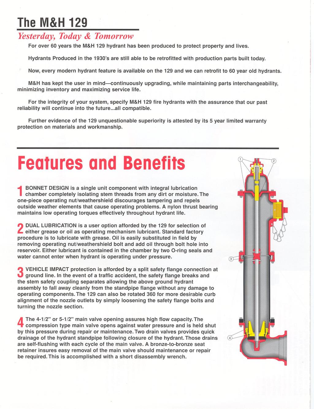
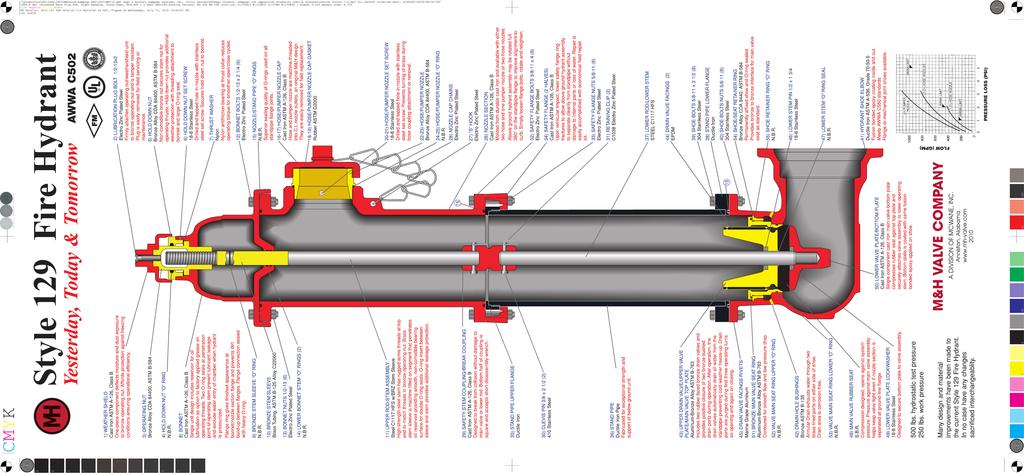
6 FEATURES AND BENEFITS M&H AWWA C502 MODEL 129 FIRE HYDRANTS YESTERDAY, TODAY, AND TOMORROW----An American Company with an American made product. M&H has been around since 1854 and have been producing hydrants since We back up our M&H 129 Fire Hydrants with a 10 Year Limited Warranty. (1) WEATHER SHIELD---One-piece cast iron component deflects moisture and dust exposure to bronze stem nut. Affords protection against freezing conditions ensuring operational efficiency. Protects bronze operating nut from pipe wrench damage commonly seen on all bronze actuated hydrants. (2) LUBRICATION PLUG BOLT---Firmly attaches operating nut / weather shield unit to bronze stem nut. Bolt fits flush with top of weather shield causing it to be tamper resistant. Using Allen wrench, plug is easily removed for field servicing or maintenance. (3) BRONZE OPERATING NUT---Primary operating component. Is a heavy duty design. Ample amounts of brass along the throat of nut. (4 & 5) HOLD DOWN NUT---Non-corrodible bronze nut secures stem nut for operating thrusts. Lock nut provides additional weather protection with threading attachment to bonnet and large O-ring seal. (6) HOLD DOWN NUT SET SCREW Stainless Steel set screw keeps hold down nut from backing out during operation. Is removed / re-installed with Allen wrench. (7) NYLON THRUST WASHER---Nylon antifriction bearing at thrust collar reduces operating torque up to 40% for smoother open / close cycles. Standard on 5 ¼ hydrants (8, 14, & 15) BONNET DESIGN / HYDRANT DUAL LUBRICATION With the single unit design, an M&H 129 Fire Hydrant customer is afforded the option of using either grease or oil as an operating mechanism lubricant. Standard factory procedure is to lubricate with grease. Oil is easily substituted in field by removing lubrication plug bolt. Two O-ring seals in bonnet prevents pressurized water from entering and lubricant from escaping into the hydrant. Bonnet flange ring gives finished appearance at bonnet / nozzle section flange. Prevents dirt build-up between flanges. Hidden flange connection sealed with heavy O-ring. (11) UPPER STEM ASSEMBLY---High strength steel stem has rugged acme threads at top end to match threads in bronze stem nut. Brass stem sleeve is machined fitted on segment that penetrates grease / oil reservoir providing smooth, non-corrodible bearing surface for double O-ring seals. O-ring inset between sleeve and stem provides additional leakage protection. (22, 23, 24, & 25) BRASS NOZZLES / NOZZLE O-RINGS---Hose and pumper nozzles are machine threaded into nozzle outlets, an original M&H design. They are easily removed for field replacement. Nozzle leak protection afforded by O-ring behind each nozzle. (20 & 21) NOZZLE SET SCREWS---Nozzles are firmly set into place by stainless steel set screw. Prevents turning of nozzle during hose coupling attachment or removal. If nozzles ever need to be replaced, setscrew can be removed using standard Allen wrench. (26) NOZZLE SECTION---Molded from durable cast iron and available with either two hose and one pumper nozzle or two hose nozzles. Has generous cross-sectional area and smoothly contoured hose outlets to deliver maximum available flow. Entire nozzle section coated with a fusion bonded polyester (26) NOZZLE SECTION 360 ROTATION / ALIGNMENT--- Above ground hydrant assembly may be rotated full 360 degrees on the standpipe flange to improve alignment to curb. This is accomplished without dismantling. Simply loosen flange bolts, rotate and re-tighten. (34) TRAFFIC IMPACT PROTECTION---Upon vehicular impact, two lower safety flange rings fracture and stem couple separates below break line. This allows the above ground hydrant assembly to separate cleanly from standpipe and keeps accidental opening of hydrant from vehicle tire. Repair is easily accomplished with economical field repair kit. (15) O-RING SEALS---Heavy Duty O-Rings provides superior sealing contact between standpipe flange joints. O-ring at break joint makes hydrant rotation easier than traditional flat gaskets. (29) TRAFFIC STEM COUPLING---Designed to break from collision without damage to main valve or rod assembly. Bottom half of coupling is square and accepts short disassembly wrench. Square design provides a direct drive area below break area for main valve seat removal and maintenance. (36) DUCTILE IRON STANDPIPE---Fabricated for exceptional strength and support below grade. HYDRANT EXTENSIONS---M&H 129 Fire Hydrants may be lengthened where ground level is being raised without digging up hydrant or requiring complete new barrel. Simply add an M&H hydrant extension available in 6 increments to the existing standpipe. (43, 44, & 45) UPPER DRAIN VALVE---Made of high strength aluminum-bronze alloy Includes double drains with rubber facings. Design provides positive closure of two bronze-bushed drain ports during operation. After operation, the drain valve quickly drains all water from the standpipe preventing cold weather freeze-up. Drain ports are purged during first three operating turns on opening and again on closing. (51) BRONZE MAIN VALVE SEAT RING---Generous amount of material and contoured design provide smooth flow and low-pressure drop. (54) BRONZE SHOE RETAINER RING----Permanently affixed to hydrant shoe with O-ring seal. Shoe Retainer Ring provides a bronze-to-bronze interface with the Main Valve Seat Ring for years for easy seat disassembly. (41) HYDRANT SHOE / ELBOW---Ductile iron hydrant shoe designed to provide smooth, even flow around valve assembly assuring highest possible flow through main valve. Coated internal and externally with fusion bonded epoxy that meets AWWA C550 standards. Provides corrosion resistance to water or soil. Mechanical Joint shoes come standard with strapping lugs for restraining hydrant shoe to pipeline. (49 & 50) LOCK WASHER / BOTTOM PLATE---Bottom plate is single component made from cast iron. Bottom plate compresses lock washer and rubber seat against top plate and securely attaches valve assembly to lower operating stem. Bottom plate is coated with same fusion bonded epoxy applied to shoe. PARTS INTERCHANGABILITY---Several design and material improvements have been made to the current Style 129 Fire Hydrant. In no case have any changes sacrificed interchangeability. Parts produced today will work on M&H hydrants produced since VALVE DISASSEMBLY---Disassembly of internal valve is achieved with the use of a Short Disassembly Wrench that engages the square end of our traffic coupling. No large removal wrench needed. VALVE OPENING SELECTION---We offer the choice between a 4 ½ and 5 ¼ valve opening on our 129 fire hydrants. APPROVALS---M&H 129 Fire Hydrants meet or exceed AWWA C502. Underwriters Laboratory and Factory Mutual approvals. TESTING---M&H 129 Fire Hydrants are individually seat tested at 250 psi followed by a 500 psi shell test to assure material and seal quality. September 2012 / M&H C502 / Model 129
7 SUGGESTED SPECIFICATIONS (1 of 2) M&H AWWA C502 FIRE HYDRANTS Model 129 Traffic Model 250 PSI Working Pressure 500 PSI Hydrostatic Test - AWWA UL / FM Approved GENERAL Fire hydrants shall comply in all respects with AWWA Standard C-502, latest revision. Fire hydrants shall be of the compression type, with the main valve opening against the pressure and closing with the pressure. The main valve opening shall be (4 ½ or 5 ¼ ) in diameter. Fire Hydrant shall be of a dry barrel, dry top design. The nozzle section shall consist of two (2) hose nozzles and one (1) pumper nozzle or other as specified. RATING Fire hydrants shall be rated at 250 psi water working pressure, tested at 500 pounds hydrostatic for structural soundness in the following manner: 500 pound hydrostatic test supplied from the inlet side, first with the main valve closed for the testing of the valve seat: second, with the main valve open for testing of the drain valves and the hydrant barrel. Testing to be complete in accordance with AWWA C-502 and UL & FM requirements. END Hydrants shall be connected to the main by a 4 or 6 fusion bonded, epoxy coated mechanical joint or CONFIGURATION flanged shoe. Mechanical joint shoes shall be fitted with strapping lugs. DESIGN The main valve seat of the hydrant shall be made of rubber and be supported by a one-piece bronze top plate / drain valve mechanism. Drain valve shall have replaceable rubber facings. The bottom stem threads of the main valve rod shall be fitted with an epoxy coated, cast iron bottom plate, sealing lower rod threads from the water. Changes in size or shape of the waterway (hydrant nozzles) shall be accomplished by means of easy curves. Exclusive of the main valve opening, the net area of the waterway of the barrel and the foot piece at the smallest part shall not be less than 120% of that of the net opening of the main valve. Hose and pumper nozzles shall be threaded and screwed into the nozzle section. And then mechanically locked to prevent turning. Hose and pumper caps shall be chained to the hydrant The hydrant shall be so designed that when it is in place, no excavation will be required to remove the main valve and movable parts of the drain valve. Further, the hydrant shall be of the type that can be extended without excavating. Hydrants shall be so designed that, in the event of accident, or breaking of the hydrant above or near grade level; the main valve will remain closed. The main valve rod shall be made in two parts and fitted with breakable coupling at the ground line flange. The ground line connection between nozzle section and the barrel shall incorporate the use of two traffic flange. This connection shall be so designed that the nozzle section can be rotated in any increment of 360. The ground line connection between the barrel and nozzle sections shall have a rubber o-ring gasket to provide a seal. The operating threads of the hydrant shall be so designed as to avoid the working of any iron or steel parts against either iron or steel. The operating stem and operating nut threads shall be square or acme type. September 2012 / M&H C502 / Model 129
8 SUGGESTED SPECIFICATIONS (2 of 2). DESIGN The operating thread shall be lubricated at factory with food grade grease. Access shall be provided (Continued) to field lubricate the operating mechanism. The operating thread shall be sealed from water at all times when the valve is either in the opened or closed position. The operating rod shall be bronze sheathed where it passes through the double O ring seal in the bonnet. The bonnet shall be weather proof and utilize a weather shield integral with the external wrench operating nut. The operating nut shall be made of bronze with a self-lubricating design. Hydrants shall be of the dry barrel type and hydrant shoe shall have two positive acting non-corrosive drain valves that shall drain the hydrant completely by opening when the main valve is closed, and close tightly in accordance with AWWA C-502 requirements when main valve is open. The main valve assembly shall be seated in the hydrant with a bronze-to-bronze interface to facilitate removal of the main valve, should maintenance be required. The nozzle section shall consist of two-2 1/2 hose nozzles to the specified thread designation (NST or other, as specified) and one pumper nozzle 4 ½ in diameter to the specified thread designation (NST or other, as specified), or other combination of nozzle outlets, including independent hose gate valves, as specified. Two O-ring seals shall be utilized where the main hydrant rod passes through the 1 piece bonnet. Hydrant standpipe shall be ductile iron and single piece for all bury depths. All like parts of hydrants of the same size and model produced by the same manufacturer shall be interchangeable. Hydrant shall open by turning to the (left or right). Direction of opening to be permanently marked on hydrant bonnet. Threads on hose and steamer nozzles shall be National Standard unless otherwise specified. Size and shape of operating nuts cap nuts shall conform to National Standard unless otherwise specified. Bury shall be (specify depth of bury) measuring depth from grade line to bottom of trench or connecting pipe. Auxiliary shut-off (isolation) gate valves, when required, shall be of the same manufacture as the hydrant. COATING Hydrant shoes shall have an interior and exterior thermosetting epoxy coating of 5 to 6 mils meeting AWWA C550. Exterior of hydrant nozzle section shall be Fire Hydrant Red (or as specified). MARKINGS Hydrant shall be marked with the name of the manufacturer, size of valve opening, direction of opening and the year of manufacture all in accordance with the AWWA C-502. Country of origin to be cast on all major hydrant castings. SOURCE Hydrants shall be M&H Model 129 or approved equal September 2012 / M&H C502 / Model 129
9 M&H VALVE COMPANY Anniston, Alabama M&H C502 Fire Hydrants TEN-YEAR LIMITED WARRANTY M&H Valve Company warrants that its AWWA C502 Fire Hydrant will be free from defects in material and workmanship under normal and customary use and maintenance for a period of ten (10) years from the date of purchase, provided the hydrant is installed and maintained according to M&H instructions, and applicable codes. The foregoing warranty does not cover failure of any part or parts from external forces, including, but not limited to, earthquake, vandalism, vehicular or other impact, application of excessive torque to the operating mechanism or frost heave. Should any M&H Valve Company part or parts fail to conform to the foregoing warranty, M&H shall, upon prompt written notice thereof, repair or replace, F.O.B. point of manufacture, such defective part or parts. Purchaser shall, if requested, return the part or parts to M&H, transportation prepaid. Purchaser shall bear all responsibility and expense incurred for removal, reinstallation and shipping in connection with any part supplied under the foregoing warranty. THE FOREGOING WARRANTY IS IN LIEU OF AND EXCLUDES ALL OTHER WARRANTIES NOT EXPRESSLY SET FORTH HEREIN, WHETHER EXPRESS OR IMPLIED BY OPERATION OF LAW OR OTHERWISE, INCLUDING, BUT NOT LIMITED TO, ANY WARRANTIES OF MERCHANTABILITY OR FITNESS. IN NO EVENT SHALL M&H VALVE COMPANY BE RESPONSIBLE OR LIABLE FOR ANY INCIDENTAL OR CONSEQUENTIAL LOSSES, DAMAGES, OR EXPENSES. September 2012 / M&H C502 Fire Hydrants
10
11
12
 GENERAL FEATURES / SPEC M&H AWWA C502 FIRE HYDRANTS Style 929 Traffic Model 250 PSI Working Pressure 500 PSI Hydrostatic Test AWWA UL / FM Approval Type: Compression type, opening against line pressure.
mh-valve.com 129 HYDRANT AWWA C502 NSF 61/372 CERTIFIED UL LISTED FM APPROVED 250 PSI WORKING PRESSURE 10-YEAR LIMITED WARRANTY
 mh-valve.com 129 HYDRANT AWWA C502 NSF 61/372 CERTIFIED UL LISTED FM APPROVED 250 PSI WORKING PRESSURE 10-YEAR LIMITED WARRANTY 129 HYDRANT YESTERDAY, TODAY, & TOMORROW For more than 85 years, the M&H
2-6 FIRE HYDRANT---(MODEL ½ & 5 ¼
 M&H PDF PAGE INDEX Page PRODUCT 2-6 FIRE HYDRANT---(MODEL 129 4 ½ & 5 ¼ ) 7 How to Order Fire Hydrants 8 FIRE HYDRANT WARRANTY 9-13 FIRE HYDRANT---(MODEL 929 5 ¼ ) 14-18 FIRE HYDRANT---(POST HYDRANT 2
mh-valve.com 129 HYDRANT AWWA C502 NSF 61/372 CERTIFIED UL LISTED FM APPROVED 250 PSI WORKING PRESSURE 10-YEAR LIMITED WARRANTY
 mh-valve.com 129 HYDRANT AWWA C502 NSF 61/372 CERTIFIED UL LISTED FM APPROVED 250 PSI WORKING PRESSURE 10-YEAR LIMITED WARRANTY 129 HYDRANT YESTERDAY, TODAY, & TOMORROW For more than 85 years, the M&H
K81-D FIRE HYDRANT GUARDIAN AWWA C502 NSF YEARS. For Generations CERTIFICATIONS ISO 9001 ISO BS OHSAS
 GUARDIAN K81-D FIRE HYDRANT CERTIFICATIONS ISO 9001 ISO 14001 BS OHSAS 18001 AWWA C502 NSF 61 140 YEARS WWW.KENNEDYVALVE.COM C For Generations COMPONENTS AND FEATURES A B C E D F G H J L M K N P Q S R
K81-DD FIRE HYDRANT GUARDIAN AWWA C502 NSF YEARS. For Generations CERTIFICATIONS ISO 9001 ISO BS OHSAS
 GUARDIAN K81-DD FIRE HYDRANT CERTIFICATIONS ISO 9001 ISO 14001 BS OHSAS 18001 AWWA C502 NSF 61 140 YEARS WWW.KENNEDYVALVE.COM C For Generations COMPONENTS AND FEATURES A B C E D F G H J K M L N P Q S R
ADMIRAL HYDRANT. clowvalve.com
 clowvalve.com ADMIRAL HYDRANT AWWA C502 UL LISTED FM APPROVED NSF 61/372 CERTIFIED 250 PSI WORKING PRESSURE 350 PSI WORKING PRESSURE AVAILABLE 10-YEAR LIMITED WARRANTY Clow Valve, A Division of McWane,
MEDALLION HYDRANT. clowvalve.com AWWA C502 UL LISTED FM APPROVED NSF 61/372 CERTIFIED 250 PSI WORKING PRESSURE 10-YEAR LIMITED WARRANTY
 clowvalve.com MEDALLION HYDRANT AWWA C50 UL LISTED FM APPROVED NSF 6/37 CERTIFIED 50 PSI WORKING PRESSURE 0-YEAR LIMITED WARRANTY Clow Valve, A Division of McWane, Inc. MEDALLION HYDRANT FIRE PROTECTION
5 1 /4 PACER. It s AMERICAN What We Know. DARLING MARK 73 2 FIRE HYDRANT AMERICAN FLOW CONTROL WATEROUS FIRE HYDRANT
 WATEROUS FIRE HYDRANT DUCTILE IRON 250 P.S.I.G. WATEROUS FIRE HYDRANT AMERICAN FLOW CONTROL It s AMERICAN What We Know. DARLING MARK 73 2 FIRE HYDRANT CONSTRUCTION WATEROUS FIRE HYDRANT TWO PIECE OPERATING
MUELLER Super Centurion fire hydrants
 MUELLER Super Centurion fire hydrants MUELLER SUPER CENTURION FIRE HYDRANT Since its introduction in 1976, millions of Centurion fire hydrants have been installed throughout the world. There are a number
Mueller Super Centurion 250 Fire Hydrant
 Mueller Super Centurion 250 Fire Hydrant Designed for efficient flow and outstanding, long-term reliability Mueller Super Centurion 250 Fire Hydrant...250 psig rating, high flow, dependable performance,
AMERICAN FLOW CONTROL 4 3/4 WATEROUS TREND FIRE HYDRANT
 AMERICAN FLOW CONTROL 4 3/4 WATEROUS TREND FIRE HYDRANT CONSTRUCTION Fully complies with ANSI/AWWA C502 and is available Listed by Underwriters Laboratories Inc. and Approved by FM Approvals in applicable
AMERICAN FLOW CONTROL 4 3/4 WATEROUS TREND FIRE HYDRANT
 AMERICAN FLOW CONTROL 4 3/4 WATEROUS TREND FIRE HYDRANT CONSTRUCTION Fully complies with ANSI/AWWA C502 and is available UL Listed and Approved by FM Approvals in applicable configurations. DUCTILE IRON
Sentinel 250 Fire Hydrant. Solid design and features to meet any municipal requirement.
 Sentinel 250 Fire Hydrant Solid design and features to meet any municipal requirement. Product Features That meet any municipal requirement. 1 Operating Nut Shields the hold down nut from tampering and
Data Sheet Issue A
 General Description The Rapidrop Fig 601/602 dry barrel post / flushing fire hydrant is designed to be a trouble free, easy to maintain hydrant. The Fig 601/602 fire hydrant is rated for a working pressure
FIRE HYDRANT SPECIFICATION CHANGE SUBMITTAL
 FIRE HYDRANT SPECIFICATION CHANGE SUBMITTAL PACKAGE CONTENT 1. Reason for Change 2. Features and Benefits Provided 3. Specification Text 4. Specification Diagram JUSTIFICATION FOR FIRE HYDRANT SPECIFICATION
AMERICAN FLOW CONTROL 5 1/4 B-84-B-5 FIRE HYDRANT
 AMERICAN FLOW CONTROL 5 1/4 B-84-B-5 FIRE HYDRANT CONSTRUCTION Fully complies with ANSI/AWWA C502 and is available Listed by Underwriters Laboratories, Inc. and Approved by FM Approvals in applicable configurations.
Super Centurion Hydrants Designed for efficient flow and outstanding, long-term reliability
 Super Centurion Hydrants Designed for efficient flow and outstanding, long-term reliability Mueller Super Centurion Fire Hydrants High flow and dependable long time performance. 1 Hold-down nut Features
American Flow control 5 1/4 B-62-B-5
 American Flow control 5 1/4 B-62-B-5 Fire Hydrant FLOW CONTROL Construction Fully complies with AWWA C502 and is available UL Listed and FM Approved in applicable configurations. one-piece bronze OPERATING
Water Distribution Solutions
 Water Distribution Solutions Table of Contents WaterMaster 5CD250 Fire Hydrants 6 WaterMaster 5BR250 Fire Hydrants 8 FlowMaster Resilient Wedge Gate Valves 11 Valve Boxes 17 Meter Boxes 22 Table of Contents
FIREFLO - MODEL F-06 INSPECTION, INSTALLATION & MAINTENANCE MANUAL. Item No.s/Description
 FIREFLO - MODEL F-06 INSPECTION, INSTALLATION & MAINTENANCE MANUAL Item No.s/Description Item No. Description Material Specification HYDRANT Qty. Req d Item No. Description Material Specification 1 Operating
Water Distribution Solutions
 Water Distribution Solutions Table of Contents WaterMaster 5CD250 Fire Hydrants 6 WaterMaster 5BR250 Fire Hydrants 8 FlowMaster Resilient Wedge Gate Valves 11 Valve Boxes 17 Meter Boxes 22 Table of Contents
American Flow control 5 1/4 b-84-b-5
 American Flow control 5 1/4 b-84-b-5 Fire Hydrant FLOW CONTROL Construction Fully complies with AWWA C502 and is available UL Listed and FM Approved in applicable configurations. one-piece bronze OPERATING
AMERICAN AVK COMPANY AVK SERIES 67 - HIGH PRESSURE, POST/FLUSHING HYDRANT FIELD MAINTENANCE AND INSTRUCTION MANUAL TABLE OF CONTENTS
 AMERICAN AVK COMPANY AVK SERIES 67 - HIGH PRESSURE, POST/FLUSHING HYDRANT FIELD MAINTENANCE AND INSTRUCTION MANUAL TABLE OF CONTENTS EXPLODED ASSEMBLY / PARTS LIST INTRODUCTION / DESCRIPTION RECEIVING
Sentinel 250 Fire Hydrant
 Maintenance Instructions manual table of contents PAGE Sentinel 250 Fire Hydrant Inspection and Lubrication 2 Rotating Hydrant to Face Desired Direction 3 Installing Extension Section 3-6 Restoring Service
CLOW CANADA - M-67 HERITAGE BRIGADIER FIRE HYDRANT SPECIFICATION
 CLOW CANADA - M-67 HERITAGE BRIGADIER FIRE HYDRANT SPECIFICATION TESTING AND DESIGN SPECIFICATIONS (PER AWWA C502 / NSF /ULC & FM) 1. Hydrant shall be manufactured in accordance with AWWA C502 latest revision
Kennedy Valve. A Division of McWane, Inc. AWWA PRODUCTS
 Kennedy Valve A Division of McWane, Inc. AWWA PRODUCTS 1021 East Water Street Elmira, NY 14902 Phone: (607)734-2211 Fax: (607)734-3288 Fax: (800)952-4771 E-Mail: sales@kennedyvalve.com www.kennedyvalve.com
FIRE PROTECTION PRODUCTS
 SUPER CENTURION FIRE HYDRANT Mueller Super Centurion Fire Hydrant Since its introduction in 1976, millions of Centurion fire hydrants have been installed throughout North America. There are a number of
AMERICAN FLOW CONTROL 5 1/4 B-62-B-5 FIRE HYDRANT
 AMERICAN FLOW CONTROL 5 1/4 B-62-B-5 FIRE HYDRANT CONSTRUCTION Fully complies with ANSI/AWWA C502 and is available UL Listed and Approved by FM Approvals in applicable configurations. ONE-PIECE BRONZE
BUTTERFLY VALVES. An industry leader in underground and in-plant applications. STYLE STYLE Consult factory for sizes
 An industry leader in underground and in-plant applications. BUTTERFLY VALVES STYLE 4500 3 24 STYLE 1450 30 54 Consult factory for sizes 60 120 C504 Class 150B & 250B M&H Valve is a division of McWane,
AMERICAN AVK COMPANY AVK SERIES 24 - HIGH PRESSURE, WET BARREL HYDRANT FIELD MAINTENANCE AND INSTRUCTION MANUAL TABLE OF CONTENTS
 AMERICAN AVK COMPANY AVK SERIES 24 - HIGH PRESSURE, WET BARREL HYDRANT FIELD MAINTENANCE AND INSTRUCTION MANUAL TABLE OF CONTENTS EXPLODED ASSEMBLY / PARTS LIST INTRODUCTION / DESCRIPTION RECEIVING AND
TABLE OF CONTENTS. 3 Outlet Stainless Steel Body. 3 Outlet Ductile Body. 2 Outlet Ductile Body 2 Outlet Bronze Body
 AVK SERIES 24 - HIGH PRESSURE, WET BARREL HYDRANT FIELD MAINTENANCE AND INSTRUCTION MANUAL TABLE OF CONTENTS EXPLODED ASSEMBLY / PARTS LIST INTRODUCTION / DESCRIPTION RECEIVING AND STORAGE INSTALLATION
5 1/4 AMERICAN-DARLING B-84-B-5 FIRE HYDRANT BY AMERICAN FLOW CONTROL
 5 1/4 AMERICAN-DARLING B-84-B-5 FIRE HYDRANT BY AMERICAN FLOW CONTROL CONSTRUCTION Fully complies with ANSI/AWWA C502 and is available UL Listed and FM Approved in applicable configurations. ONE-PIECE
AVK SAUDI VALVES MANUFACTURING COMPANY
 AVK SAUDI VALVES MANUFACTURING COMPANY AVK SERIES 24 - HIGH PRESSURE, WET BARREL HYDRANT FIELD MAINTENANCE AND INSTRUCTION MANUAL TABLE OF CONTENTS EXPLODED ASSEMBLY / PARTS LIST INTRODUCTION / DESCRIPTION
SECTION VIII. (Sub-section 430) Wastewater Valves and Appurtenances. 1. General thru Gate Valves thru 430-3
 Wastewater Valves and Appurtenances. 1. General thru Gate Valves thru 430-3") SECTION VIII (Sub-section 430) Wastewater Valves and Appurtenances Article Page 1. General 430-1 thru 430-2 2. Gate Valves 430-2 thru 430-3 3. Plug Valves 430-3 thru 430-4 4. Check Valves 430-4 5. Tapping
SECTION VIII (Sub-section 430) Wastewater Valves and Appurtenances Article Page 1. General 430-1 thru 430-2 2. Gate Valves 430-2 thru 430-3 3. Plug Valves 430-3 thru 430-4 4. Check Valves 430-4 5. Tapping
OPERATION AND MAINTENANCE MANUAL 5-1/4 AMERICAN-DARLING B-84-B-5 FIRE HYDRANT
 OPERATION AND MAINTENANCE MANUAL 5-1/4 AMERICAN-DARLING B-84-B-5 FIRE HYDRANT INDEX 5-1/4 AMERICAN-DARLING B-84-B-5 FIRE HYDRANT OPERATION AND MAINTENANCE MANUAL OPERATION AND MAINTENANCE REPAIRS Operation
K81 Guardian Fire Hydrants. Operation & Maintenance Guide
 Kennedy Valve K81 Guardian Fire Hydrants Operation & Maintenance Guide Installation 1. When hydrants are received from manufacturer they should be handled carefully to avoid breakage and damage to flanges.
VSI. Series BFII WATERWORKS. BUTTERFLY VALVES CONFORMING TO AWWA C504 Replaceable Seated 24-Inch and Greater Butterfly Valve
 M M Series BFII BUTTERFLY VALVES CONFORMING TO AWWA C504 Replaceable Seated 24-Inch and Greater Butterfly Valve Publication 504-106 Issue 06/12 Design Features General All AWWA Butterfly Valves are of
MUELLER Hydrant Security Device
 MUELLER HYDRANT DEFENDER SECURITY DEVICE 9A. Rev. 8-04 When conducting a vulnerability assessment (V.A.), infiltration of a municipal water supply through an unsecured fire hydrant should be a primary
OPERATION AND MAINTENANCE MANUAL 5-1/4 AMERICAN-DARLING B-62-B-5 FIRE HYDRANT
 OPERATION AND MAINTENANCE MANUAL 5-1/4 AMERICAN-DARLING B-62-B-5 FIRE HYDRANT INDEX 5-1/4 AMERICAN-DARLING B-62-B-5 FIRE HYDRANT OPERATION AND MAINTENANCE MANUAL OPERATION AND MAINTENANCE REPAIRS Operation
SIGELOCK SPARTAN FIRE HYDRANT. Operation and Maintenance Guide. Sigelock Systems, LLC 10 Bulaire Road East Rockaway, NY sigelock.
 SIGELOCK SPARTAN FIRE HYDRANT Operation and Maintenance Guide Sigelock Systems, LLC 10 Bulaire Road East Rockaway, NY 11518 sigelock.com CONTACING SIGELOCK SYSTEMS If after reading the following instructions,
FIRE HYDRANTS. Wet Barrel Fire Hydrants
 FIRE HYDRANTS Wet Barrel Fire Hydrants Jones Wet Barrel Fire Hydrants With over 100 years of experience on the west coast the heart of the wet barrel market James Jones Company is the innovator in the
VALVES, FIRE HYDRANTS, AND APPURTENANCES
 VALVES, FIRE HYDRANTS, AND APPURTENANCES PART 1 - GENERAL 1.01 SECTION INCLUDES A. Butterfly Valves B. Gate Valves C. Tapping Valve Assemblies D. Fire Hydrant Assemblies E. Flushing Devices (Blowoffs)
1. Valves shall conform to the latest version of AWWA Standard C-509 covering Resilient Seated gate Valves for Water Supply Service.
 KENNEDY KENNEDY VALVE MODEL VALVE KS-RW 1. Valves shall conform to the latest version of AWWA Standard C-509 covering Resilient Seated gate Valves for Water Supply Service. 2. The valves shall have a cast
516509_tabs 11/16/10 4:55 AM Page 1 FIRE HYDRANTS
 Date Printed: November 2010 FIRE HYDRANTS or Tyton (6"),6, or 8" A EDDY FIRE HYDRANTS PARTS LIST WORKING PRESSURE: 150 PSI Note: Discontinued For Reference Only 350 PSI Working Pressure
SIGELOCK SPARTAN FIRE HYDRANT. Operation and Maintenance Guide. Sigelock Systems, LLC 3205 Lawson Boulevard Oceanside, NY sigelock.
 SIGELOCK SPARTAN FIRE HYDRANT Operation and Maintenance Guide Sigelock Systems, LLC 3205 Lawson Boulevard Oceanside, NY 11572 sigelock.com CONTACTING SIGELOCK SYSTEMS If after reading the following instructions,
Harlingen Water Works System Approved Products List For Subdivisions. January 11, 2005
 Harlingen Water Works System Approved Products List For Subdivisions January 11, 2005 Revised March 24, 2016 Harlingen Water Works System Approved Products List for Subdivisions Table of Contents: 1. Valves
Hydrants. Waterous WB The Pacer. American-Darling B-84-B. American-Darling B-62-B. Clow Eddy F Abbreviations Common to Hydrants
 Revised 6/01 Hydrants Waterous WB-67-250 The Pacer In 1886, Waterous introduced their line of Frost Jacket fire hydrants. The traffic model WB-67-250 brings the developments of the last one hundred plus
Trend Hydrants. Installation, Operation, Maintenance and Overhaul Instructions. Table of Contents. Illustrations. Tables H /16/10 12/04/95
 Installation, Operation, Maintenance and Overhaul Instructions Form No. H-351 Date 12/04/95 Revision Date 02/16/10 Trend Hydrants New Style Trend Old Style Trend Model WB77 Wet Top Model WT77 Dry Top Model
AMERICAN AVK COMPANY AVK SERIES HIGH PRESSURE, MODERN, DRY BARREL HYDRANT FIELD MAINTENANCE AND INSTRUCTION MANUAL TABLE OF CONTENTS
 AMERICAN AVK COMPANY AVK SERIES 2700 - HIGH PRESSURE, MODERN, DRY BARREL HYDRANT FIELD MAINTENANCE AND INSTRUCTION MANUAL TABLE OF CONTENTS EXPLODED ASSEMBLY / PARTS LIST INTRODUCTION / DESCRIPTION RECEIVING
EXPECT RELIABILITY AVK RESILIENT SEATED GATE VALVES
 EXPECT RELIABILITY AVK RESILIENT SEATED GATE VALVES AVK VALVES STANDARD FEATURES AVK STANDARD FEATURES AVK Gate Valves are made of ductile iron and meet or exceed AWWA C509 or C515 ASTM A582 stainless
INDEX WATEROUS 5 1/4 IN. PACER FIRE HYDRANT
 INDEX WATEROUS 5 1/4 IN. PACER FIRE HYDRANT PAGE INTRODUCTION AND HISTORY............................................................. 2B 2 ORDERING Dimensions: Overall Hydrant...............................................................
MUELLER. Centurion Series Fire Hydrant. Centurion Super Centurion 200 Super Centurion 250. Reliable Connections. Background and Forward 2
 operating Instructions manual MUELLER table of contents PAGE Background and Forward 2 Centurion Series Fire Hydrant Centurion Super Centurion 200 Super Centurion 250 Handling and Inspection 3 Installation
SUB WATER DEPARTMENT STANDARD CONSTRUCTION SPECIFICATIONS TABLE OF CONTENTS SECTION WATER DISTRIBUTION VALVES
 SUB WATER DEPARTMENT STANDARD CONSTRUCTION SPECIFICATIONS TABLE OF CONTENTS SECTION 33 12 16 WATER DISTRIBUTION VALVES PART 1 GENERAL... 2 1.1 Description... 2 1.2 Reference Specifications, Codes, and
FLOAT CONTROL VALVES
 PROJECT NAME LOCATION FLOAT CONTROL VALVES INTRODUCTION This specification covers the design, manufacture, and testing of 8 in. (200 mm) through 36 in. (900 mm) Control Valves PART 1 - GENERAL 1. Standard
PRODUCT MANUAL 5-1/4 AMERICAN-DARLING B-84-B-5 FIRE HYDRANT
 PRODUCT MANUAL 5-1/4 AMERICAN-DARLING B-84-B-5 FIRE HYDRANT INDEX 5-1/4 AMERICAN - DARLING B-84-B-5 FIRE HYDRANT INTRODUCTION AND HISTORY... 1B-2 ORDERING Dimensions: Overall Hydrant... 1B-3 Optional Bases...1B-4
AMERICAN AVK COMPANY AVK SERIES HIGH PRESSURE, NOSTALGIC, DRY BARREL HYDRANT FIELD MAINTENANCE AND INSTRUCTION MANUAL TABLE OF CONTENTS
 AMERICAN AVK COMPANY AVK SERIES 2780 - HIGH PRESSURE, NOSTALGIC, DRY BARREL HYDRANT FIELD MAINTENANCE AND INSTRUCTION MANUAL TABLE OF CONTENTS EXPLODED ASSEMBLY / PARTS LIST INTRODUCTION / DESCRIPTION
Rev. 2/16 MUELLER Fire Hydrant Reference Manual Mueller Co. Printed in the U.S.A.
 Rev. 2/16 MUELLER Fire Hydrant Reference Manual 2016 Mueller Co. Printed in the U.S.A. Index 1 Fire Hydrant Reference Material Index Index...1 Identification...2-36 Dry Barrel Hydrants - AWWA...3-21 Dry
Slide Gate Hydrant Maintenance Manual
 Slide Gate Maintenance Manual Terminal City Iron Wks Ltd. Unit#3 99 19th Street, Langley, BC V1M 3C This Maintenance Manual is intended to give a guide to Maintenance. The Manual covers: Maintenance and
SECTION FIRE HYDRANTS WITH HYDRANT LOCKS
 SECTION 33 12 19 FIRE HYDRANTS WITH HYDRANT LOCKS PART 1: GENERAL 1.01 SCOPE A. Fire hydrants. B. Adjustment of fire hydrants and gate valves. 1.02 SUBMITTALS A. Conform to requirements of Section 01 33
SECTION 8 Fire Protection
 Bronze Wet Barrel Fire Hydrants With over 100 years of experience on the west coast the heart of the wet barrel market James Jones Company, LLC is the innovator in the bronze wet barrel hydrant industry.
American Flow control Series 2500
 American Flow control 14-66 Series 2500 Resilient wedge gate valve FLOW CONTROL Construction Ductile iron operating nut Provides strength and durability. Lifting DEVICES 14-66 Valve is constructed of high-strength
SWING CHECK VALVES SERIES 52-SC SERIES 600
 SWING CHECK VALVES SERIES 52-SC SERIES 600 FEATURES/BENEFITS/SPECIFICATIONS AMERICAN Flow Control Series 52-SC Swing Check Valves incorporate design features to help increase service life for water and
Val-Matic 3-Way Tapered Plug Valve
 Val-Matic 3-Way Tapered Plug Valve Manual No. CCPV-OM4-1 Operation, Maintenance and Installation Manual INTRODUCTION.2 RECEIVING AND STORAGE 2 VALVE CONSTRUCTION..2 DESCRIPTION OF OPERATION. 3 INSTALLATION
of wet barrel hydrants, hydrant valves and hydrant tools.
 JONES WET BARREL FIRE HYDRANTS The most complete selection of wet barrel hydrants, hydrant valves and hydrant tools. Bronze wet barrel fire hydrants Jones is the leader. With over 100 years of experience
SOLENOID CONTROL VALVE
 PROJECT NAME LOCATION SOLENOID CONTROL VALVE INTRODUCTION This specification covers the design, manufacture, and testing of 4 in. (100 mm) through 36 in. (900 mm) Control Valves PART 1 - GENERAL 1. Standard
PROJECT TITLE PROJECT NO: CONTRACT TITLE GRANT NO: UNIVERSITY OF CALIFORNIA, DAVIS CITY, CALIFORNIA
 The following standard specification is intended to be edited according to the specifics of the project. Brackets [ ] and areas shaded in gray [e.g. format] indicate requirements that are optional depending
PRESSURE REDUCING CONTROL VALVES
 PROJECT NAME LOCATION PRESSURE REDUCING CONTROL VALVES INTRODUCTION This specification covers the design, manufacture, and testing of 1 in. (25 mm) through 36 in. (900 mm) Control Valves PART 1 - GENERAL
INDEX WATEROUS 5-1/4 IN. PACER FIRE HYDRANT
 INDEX WATEROUS 5-1/4 IN. PACER FIRE HYDRANT PAGE INTRODUCTION AND HISTORY.............................................................. 2B-2 ORDERING Dimensions: Overall Hydrant...............................................................
ALTITUDE CONTROL VALVES FOR ONE WAY FLOW
 PROJECT NAME LOCATION ALTITUDE CONTROL VALVES FOR ONE WAY FLOW INTRODUCTION This specification covers the design, manufacture, and testing of 2 in. (50 mm) through 36 in. (900 mm) Control Valves PART 1
MILLCENTRIC FULL/100% POR T ECCENTRIC PLUG VALVE
 ISO 9001 CERTIFIED MILLCENTRIC FULL/100% POR T ECCENTRIC PLUG VALVE Suggested Specifications The Milliken criteria of quality, reliability, safety and value are embodied in the Millcentric Eccentric valve,
According to AWWA-standard
 According to -standard Water Fire fighting - UL/FM 304 Gate valves - Cast iron 320 Gate valves OS&Y 306 Service connection valves 322 Post indicators 306 Combi valves 307 Gate valves - 310 Gate valves
Butterfly Valve. Product Training Presentation Danfoss Flomatic Corporation
 Click to see: Butterfly Valves in our Online Catalog Butterfly Valve Product Training Presentation Danfoss Flomatic Corporation REV:082303 Butterfly Valve SYLAX SERIES 149G BUTTERFLY VALVES Wafer and Lug
ECCENTRIC PLUG VALVES
 Serving the Water & Waste Water Industry Since 1878 ECCENTRIC PLUG VALVES C517 3 24 sizes available Multiple end connections available M&H Valve is a division of McWane, Inc. www.mh-valve.com AVAILABLE
Lineseal Butterfly Valves 150B, 250B, & 350B Class; Sizes 3-48
 Lineseal Butterfly Valves 0B, 0B, & 0B Class; Sizes -8 Mueller Lineseal Butterfly Valves Sizes -8 Performance is key. Designed specifically for the waterworks industry, Lineseal butterfly valves offer
Suggested Specifications
 ISO 9001 Certified Suggested Specifications The Milliken criteria of quality, reliability, safety and value are embodied in the Millcentric Eccentric valve, setting higher standards for dependable performance
PRESSURE RELIEF / SUSTAINING CONTROL VALVES
 PROJECT NAME LOCATION PRESSURE RELIEF / SUSTAINING CONTROL VALVES INTRODUCTION This specification covers the design, manufacture, and testing of 1 in. (25 mm) through 36 in. (900 mm) Control Valves PART
SAN ANTONIO WATER SYSTEM SPECIFICATIONS FOR RUBBER-SEATED BUTTERFLY VALVES 3 INCHES THROUGH 72 INCHES ANSI/AWWA C504 Class 150/250 December 2012
 SAN ANTONIO WATER SYSTEM SPECIFICATIONS FOR RUBBER-SEATED BUTTERFLY VALVES 3 INCHES THROUGH 72 INCHES ANSI/AWWA C504 Class December 2012 1. SCOPE This product specification covers class rubber-seated butterfly
MUELLER. Super Centurion 350 Fire Hydrant. Reliable Connections. Inspection and Maintenance 2. Filling Oil Reservoir 3. Facing the Hydrant 4
 operating Instructions manual MUELLER Super Centurion 350 Fire Hydrant table of contents PAGE Inspection and Maintenance 2 Filling Oil Reservoir 3 Facing the Hydrant 4 Restoring Service after Traffic Knockover
Watts Series CSM-91. Grooved/Flanged Flow Measurement/Balancing Valves. Installation and Operating Instructions. Table of Contents. 1.
 Watts Series CSM-9 Grooved/Flanged Flow Measurement/Balancing Valves Installation and Operating Instructions IS-CSM-9 Table of Contents Item Description Page. Installation of Valve Angle Design 2. Installation
TABLE OF CONTENTS. American AVK Company An ISO registered company
 AVK SERIES 2780 - HIGH PRESSURE, NOSTALGIC, DRY BARREL HYDRANT FIELD MAINTENANCE AND INSTRUCTION MANUAL TABLE OF CONTENTS EXPLODED ASSEMBLY / PARTS LIST INTRODUCTION / DESCRIPTION RECEIVING AND STORAGE
AMERICAN FLOW CONTROL 3-16 SERIES 2100 RESILIENT SEATED CHECK VALVE
 AMERICAN FLOW CONTROL 3-16 SERIES 2100 RESILIENT SEATED CHECK VALVE CONSTRUCTION STAINLESS STEEL PIPE PLUG Allows installation of pressure gauge. STAINLESS STEEL FASTENERS Helps provide corrosion resistance.
SECTION COMMON WORK RESULTS FOR FIRE SUPPRESSION. A. Pipe, fittings, valves, and connections for sprinkler systems.
 SECTION 210500 - COMMON WORK RESULTS FOR FIRE SUPPRESSION PART 1 GENERAL 1.1 SECTION INCLUDES A. Pipe, fittings, valves, and connections for sprinkler systems. 1.2 RELATED REQUIREMENTS A. Section 099000
SECTION 17 FIRE HYDRANT ASSEMBLIES General
 SECTION 17 FIRE HYDRANT ASSEMBLIES 17-1.01 Scope 17-1 General This section describes the requirements for furnishing and installing as appurtenances to treated water mains. These requirements include the
24-48 HP250II Butterfly Valve. Operation and Maintenance Manual. Job Name: Contractor: Date: Document #: 2448HP250OOOM Revision Date: 1/10/11
 24-48 HP250II Butterfly Valve Operation and Maintenance Manual Job Name: Contractor: Date: Document #: 2448HP250OOOM Revision Date: 1/10/11 SAFETY MESSAGES All safety messages in the instructions are flagged
COMBINATION PRESSURE REDUCING AND SOLENOID SHUTOFF CONTROL VALVES 2.01 COMBINATION RESSURE REDUCING AND SOLENOID SHUTOFF CONTROL VALVE
 PROJECT NAME LOCATION COMBINATION PRESSURE REDUCING AND SOLENOID SHUTOFF CONTROL VALVES INTRODUCTION This specification covers the design, manufacture, and testing of 1 in. (25 mm) through 36 in. (900
SECTION SWING CHECK VALVES
 PART 1 GENERAL 1.1 DESCRIPTION This section includes materials, testing, and installation of swing check valves as shown in the Drawings and specified herein, in accordance with the requirements of the
PRESSURE RELIEF / SURGE ANTICIPATOR CONTROL VALVE
 PROJECT NAME LOCATION PRESSURE RELIEF / SURGE ANTICIPATOR CONTROL VALVE INTRODUCTION This specification covers the design, manufacture, and testing of 2-1/2 in. (65 mm) through 18 in. (450 mm) Control
Sanitary Roof Hydrant Installation Instructions
 Installation Instructions Freeze Flow hydrants are designed for heavy-duty commercial use where safe potable water is needed. This hydrant drains into the canister below the roof line to prevent freeze
BUTTERFLY VALVES KENNEDY 140 YEARS AWWA C504 CLASS 150B & 250B CERTIFICATIONS ISO 9001 ISO BS OHSAS
 KENNEDY BUTTERFLY S CERTIFICATIONS ISO 9001 ISO 14001 BS OHSAS 18001 AWWA C504 CLASS 150B & 250B STYLE 4500 3-24 STYLE 1450 30-54 CONSULT KENNEDY FOR SIZES LARGER THAN 54 INCHES. 140 YEARS WWW.KENNEDY.COM
Val-Matic 1-4 Combination Air Valve (Single Housing Type)
") Manual No. ARCO-OM1-2 Val-Matic 1-4 Combination Air Valve (Single Housing Type) Operation, Maintenance and Installation Manual INTRODUCTION... 1 RECEIVING AND STORAGE... 1 DESCRIPTION OF OPERATION... 1
Manual No. ARCO-OM1-2 Val-Matic 1-4 Combination Air Valve (Single Housing Type) Operation, Maintenance and Installation Manual INTRODUCTION... 1 RECEIVING AND STORAGE... 1 DESCRIPTION OF OPERATION... 1
Val-Matic 3-72 Cam-Centric Plug Valve
 Manual No. CCPV-OM2-8 Val-Matic 3-72 Cam-Centric Plug Valve Operation, Maintenance and Installation Manual INTRODUCTION... 2 RECEIVING AND STORAGE... 2 DESCRIPTION OF OPERATION... 2 VALVE CONSTRUCTION...
HP250II AND HP250 BUTTERFLY VALVES Engineering Creative Solutions for Fluid Systems Since 1901
 H250II AND H250 BUTTERFLY VALVES Engineering Creative Solutions for Fluid Systems Since 1901 TABLE OF CONTENTS RATT H250II Scope of Line... 1 Design and Construction Details... 1 ipe Mating Chart... 1
MODULATING FLOAT CONTROL VALVE
 PROJECT NAME LOCATION MODULATING FLOAT CONTROL VALVE INTRODUCTION This specification covers the design, manufacture, and testing of 2 in. (50 mm) through 36 in. (900 mm) Control Valves PART 1 - GENERAL
M&H AWWA C508 STANDARD SWING CHECK VALVES
 GENERAL M&H AWWA C508 STANDARD SWING CHECK VALVES Style 59-02 plain / 159-Lever & Weight / 259-02 Lever & Spring Sizes 2 Through 36 Water / Sewage Service M&H Swing Check valves are widely specified by
Val-Matic 3"-24" Butterfly Valve With LSA Actuator and External Stops
 Manual No. BFV-OM3-6 Val-Matic 3"-24" Butterfly Valve With LSA Actuator and External Stops Operation, Maintenance and Installation Manual INTRODUCTION... 2 RECEIVING AND STORAGE... 2 DESCRIPTION OF OPERATION...
AVK SERIES 41 SWING CHECK VALVE FIELD MAINTENANCE AND INSTRUCTION MANUAL FOR SWING CHECK VALVES 3" - 12"
 AMERICAN AVK COMPANY AVK SERIES 41 SWING CHECK VALVE FIELD MAINTENANCE AND INSTRUCTION MANUAL FOR SWING CHECK VALVES 3" - 12" TABLE OF CONTENTS EXPLODED ASSEMBLY / PARTS LIST INTRODUCTION / DESCRIPTION
2-12 Grooved End Dual Disc Check Valve. Operation, Maintenance and Installation Manual
 Manual No. DDCV-OM4-1 2-12 Grooved End Dual Disc Check Valve Operation, Maintenance and Installation Manual INTRODUCTION... 1 RECEIVING AND STORAGE... 1 DESCRIPTION OF OPERATION... 1 INSTALLATION... 2
BUTTERFLY VALVE - WAFER FAF 3500
 PRODUCTION STANDARDS DN40 DN600 PN 6-10-16 CLASS 150 Design EN 593 Connection Wafer Type ISO 7005-1 EN 1092-1 Face to Face EN 558 Series 20 Marking EN 19 Tests EN 12266-1 Corrosion Protection Electrostatic
AVK SERIES 41 SWING CHECK VALVE FIELD MAINTENANCE AND INSTRUCTION MANUAL FOR SWING CHECK VALVES 3" - 12"
 AMERICAN AVK COMPANY AVK SERIES 41 SWING CHECK VALVE FIELD MAINTENANCE AND INSTRUCTION MANUAL FOR SWING CHECK VALVES 3" - 12" TABLE OF CONTENTS EXPLODED ASSEMBLY / PARTS LIST INTRODUCTION / DESCRIPTION