Fieldbus Electronics. G3 Communication Node and I/O 580 Communication Node.
|
|
|
- Cory Simmons
- 5 years ago
- Views:
Transcription

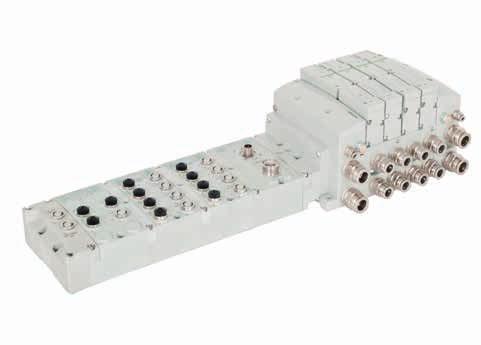


1 Fieldbus Electronics G3 Communication Node and I/O 580 Communication Node
2
3 Table of Contents G3 Electronics Features and Benefits 2 G3 Platform Distribution Options 4 DeviceNet 6 Ethernet 7 PROFIBUS DP 8 PROFINET 9 CANopen 10 DeviceLogix 11 Ethernet POWERLINK EtherCAT 13 EtherNet/IP DLR 14 CC-Link IE Field 15 I/O Modules 16 Input Modules - RTD & NAMUR IS 18 Sub-bus Modules 19 Miscellaneous Modules & Accessories 21 G3 Fieldbus Manifold Assembly 23 G3 Electronics 24 Sub-bus Valve Manifolds 26 G3 Assembly Kit and G3 Electronics 27 Complete G3 Manifold Assembly Series Series R2 & 02 Series Series Series Series 39 ISO mm Series 41 ISO mm Series 43 ISO 5599/2 Series 45 Cables & Connectors 47 DeviceNet /CANopen Cables & Connectors 50 PROFINET Cables & Connectors 51 Ethernet POWERLINK Cables & Connectors 52 PROFIBUS DP Cables & Connectors 53 EtherCAT Cables & Connectors 54 Ethernet Cables & Connectors 55 CC-Link IE Field Cables & Connectors 56 I/O Cables & Connectors 57 Sub-bus Cables & Connectors Series Features and Benefits 62 DeviceNet 63 EtherNet/IP 64 PROFIBUS DP 65 PROFINET 66 EtherCAT 67 EtherNet/IP DLR 68 IO-Link CHARM Node Fieldbus Communication Assembly Dimensions 71 How to Order 580 Assembly Kit and 580 Electronics 72 How to Order Complete 580 Manifold Assembly 73 Cables and Connectors 74
 Set baud rate Set auto or manual I/O sizes Set fault/idle output states Set brightness Set factory defaults")


4 G3 Fieldbus - Electronics Made Easy! Innovative Graphic Display is used for easy commissioning, visual status & diagnostics. Commissioning Capabilities Set network address (including IP & Subnet mask for Ethernet) Set baud rate Set auto or manual I/O sizes Set fault/idle output states Set brightness Set factory defaults Visual diagnostics Shorted and open load detection Shorted sensor/cable detection Low & missing power detection Missing module detection Self-test activation Log of network errors Distribution errors Graphic Display for Configuration & Diagnostics Auto Recovery Module G3 Fieldbus Communications Electronics Why use Numatics Fieldbus communication electronics? Modular Reality... No internal wiring simplifies assembly SPEEDCON M connector technology allows for fast and efficient ½ turn I/O connector attachment Power connector allows output power to be removed while inputs and communication are left active IP65 protection Up to 00 Input/00 Output capability with one communication node! (Present physical I/O combinations allows 00 I/544 O) 32 valve solenoids per manifold, up to 17 manifolds per communication node! One node supports 16 I/O modules Analog I/O, Digital I/O (NPN & PNP) and Specialty Innovative clip design allows easy module removal/ replacement without dismantling manifold Auto Recovery Module (ARM) protects configuration information during a critical failure. Allows configuration information to be saved and reloaded to replacement module automatically Highly Distributable Supported Protocols DeviceNet DeviceNet w/ QuickConnect DeviceNet w/ DeviceLogix Ethernet PROFIBUS DP Easy, Robust Connections CANopen PROFINET Ethernet POWERLINK EtherCAT EtherNet/IP DLR w/quickconnect CC-Link IE Field 2 * Numatics I/O with SPEEDCON technology 1/2 turn for faster I/O connections Backwards compatible with standard M cables/connectors Meets the same IP/NEMA standards as M/Micro cables/connectors Same cost as standard M/Micro cables/connectors See page 56 for cables with SPEEDCON connector technology DeviceNet and QuickConnect are trademarks of ODVA. DeviceLogix is a trademark of Rockwell Automation, Inc. PROFIBUS and PROFINET are registered trademarks of Profibus Nutzerorganisation e.v. CANopen is a registered Community trademark of CAN in Automation e.v. Ethernet POWERLINK is a registered trademark of Bernecker + Rainer Industrie Elektronik Ges.m.b.H. CC-Link is a registered trademark and CC-Link IE Field is a trademark of the CC-Link Partner Association. *

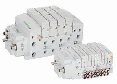
5 G3 Electronics Modularity Discrete I/O The G3 Series product line is a completely modular system. All of the G3 electronic modules plug together, via mechanical clips, allowing easy assembly and field changes. This makes the system highly distributable. Additional flexibility is incorporated because the same modules can be used in either centralized or distributed applications. The G3 electronics interfaces with the highly modular Numatics 500 Series, Generation 2000 Series, ISO 5599/2 and ISO Series valve lines to further enhance the modularity and flexibility of the entire system. Sub-bus Out or Terminator Module Jumper Clips I/O Labels Auto Recovery Module (ARM) I/O Modules - Analog or Digital, NPN or PNP Communication Module (Node) Valve Manifold Assembly 501, 502, 503, 2002, 2005, 20, 2035, ISO & ISO 5599/2 Series Valves DIN Rail Mounting Option 3
 Sub Manifold with Valves I/O Only Sub Manifold with I/O & Valves Sub-bus Out 24 VDC Power Supply Sub-bus 24 VDC")

6 G3 Platform Distribution Options Easy, Cost Effective Solutions for Digital I/O and Valve Automation using G3 Electronics. Main Fieldbus Manifold Sub-bus Sub-bus Out Sub-bus In 24 VDC Power Supply (optional) Sub Manifold with Valves I/O Only Sub Manifold with I/O & Valves Sub-bus Out 24 VDC Power Supply Sub-bus 24 VDC Power Supply Unique distribution system allows system efficiency by allowing the same modules to be used in either centralized or distributed applications Distribution options include: Inputs OR Outputs Inputs AND Outputs Valves with Inputs AND Outputs Valves with Inputs OR Outputs Valves Only Maximum Sub-bus length not to exceed 30 meters. Maximum Sub-bus cable current not to exceed 4 amps or excessive cable voltage drops per segment. Auxiliary power connections available for currents above 4 amps. Consult factory for possible deviations 4


 Modules include analog and")
7 G3 Platform Distribution Options The G3 platform is flexible to the point that there are a virtually infinite number of I/O distribution options using the few basic G3 modules. The following basic rules should be followed in the configuration of your control architecture. Typical Main Fieldbus Manifold Valve Side Up to a total of 32 valve solenoids can be driven in a manifold assembly integrated into the Main Fieldbus Manifold. This can be any number of single or double solenoid valves with a total number of solenoids not to exceed 32 A valve side output module is available. If a valve side output module is used, 16 outputs are allocated to the solenoids in the integral manifold and 16 are allocated to the output module in the manifold Comm. Module I/O Side Valve Side I/O Side Distribution A total of 16 modules can be integrated into the network and controlled by the main fieldbus communication module (node) Modules include analog and digital I/O modules providing addressing capacity for up to 00 Inputs/00 Outputs per node Unique distribution system allows system efficiency by allowing the same modules to be used in either centralized or distributed applications Distribution options include Inputs only, Outputs only, I/O only, valves with Inputs, valves with Outputs and valves with I/O Configuration can include up to 16 of the following modules: Digital I/O modules Sub-bus valve modules Analog I/O modules Comm. Module I/O Side 16 Modules can be supported on this side of the comm. module Comm. Module 5
8 DeviceNet DeviceNet is an open bus fieldbus communication system developed by Allen-Bradley based on Controller Area Network (CAN) technology. The governing body for DeviceNet is the Open DeviceNet Vendors Association (ODVA). The ODVA controls the DeviceNet specification and oversees product conformance testing. Numatics G3 nodes for DeviceNet have an integrated graphic display and are capable of addressing combinations of up to 00 outputs and 00 inputs. They have been tested and approved for conformance by the ODVA. More information about DeviceNet and the ODVA can be obtained from the following website: Technical Data Description DeviceNet Communications Module (node) Electrical Data Voltage Current Node Power at Max. Brightness 24 VDC +/- 10% Amps Bus Power VDC Amps Valves & Discrete I/O 24 VDC +/- 10% 8 Amps Maximum Power Connector Single key 4 pin 7/8" MINI type (male) Communication Connector Single key 5 pin 7/8" MINI type (male) LEDs Module Status and Network Status Replacement Part Number Temperature Range (ambient) Humidity Vibration/Shock Moisture Protection Operating Data -23 C to 46 C (-10 F to 115 F) 95% relative humidity, non-condensing IEC , IEC IP65 (with appropriate assembly and termination) Graphic Display Configuration Data Display used for setting Node Address, Baud Rate, Fault/Idle Actions, DeviceNet w/quickconnect and all other system settings ARM (Auto Recovery Module) Optional module that contains automatic recovery of system setting in the event of total or partial system failure Maximum Valve-Solenoid Outputs 32 Maximum Addressable I/O Points Various combinations of 00 outputs and 00 inputs Supported Baud Rates Supported Connection Type Bus Connector Diagnostics Special Features Network Data 5K Baud, 250K Baud, 500K Baud, with Auto-Baud detection Polled, Cyclic, Change of State (COS) and combination Message Capability Single key 5 pin 7/8" MINI type (male) Power, short, open load conditions and module health are monitored Supports Auto-Device Replacement (ADR) and fail-safe device settings 6 Weight DeviceNet Communications Module 252g/8.9 oz
9 Ethernet (EtherNet/IP & Modbus TCP/IP) Ethernet used throughout the world to network millions of PCs has now evolved into a viable industrial network. Ethernet is an open architecture high-level communication network that meets the demands of today s industrial applications requiring high-speed (10/100 Mbit/s), high-throughput and flexibility. Additionally, Ethernet technology can integrate an on-board web server, which can make the node readily accessible to any standard web browser for configuration, testing and even retrieval of technical documentation. Numatics G3 nodes for Ethernet have an integrated graphic display and are capable of addressing combinations of up to 00 outputs and 00 inputs. The G3 EtherNet/IP nodes have been tested and approved for conformance by the ODVA. More information about EtherNet/IP and the ODVA can be obtained from the following website: Technical Data Description EtherNet/IP Communications Module (node) Modbus TCP/IP Communications Module (node) Electrical Data Voltage Current Node Power at Max. Brightness 24 VDC +/- 10% Amps Valves & Discrete I/O 24 VDC +/- 10% 8 Amps Maximum Power Connector Single key 4 pin 7/8" MINI type (male) Communication Connector D-coded 4 pin M type (female) LEDs Module Status, Network Status and Activity/Link Replacement Part Number Temperature Range (ambient) Humidity Vibration/Shock Moisture Protection Operating Data -23 C to 46 C (-10 F to 115 F) 95% relative humidity, non-condensing IEC , IEC IP65 (with appropriate assembly and termination) Configuration Data Graphic Display Display used for setting IP Address, Subnet mask, Fault/Idle Actions, DHCP/BootP and all other system settings ARM (Auto Recovery Module) Optional module that contains automatic recovery of system setting in the event of total or partial system failure Maximum Valve-Solenoid Outputs 32 Maximum Addressable I/O Points Various combinations of 00 outputs and 00 inputs Supported Baud Rates Bus Connector Diagnostics Special Features Network Data 10 Mbit/100 Mbit D-coded 5 pin M type (female) Power, short, open load conditions and module health are monitored Integrated web server, fail-safe device settings, HTTP, FTP, and UNICAST (for EtherNet/IP ) Weight Ethernet Communications Module 255g/9 oz 7
10 PROFIBUS DP PROFIBUS DP is a vendor-independent, open fieldbus protocol designed for communication between automation control systems and distributed I/O at the device level. Numatics G3 nodes for PROFIBUS DP have an integrated graphic display and are capable of addressing combinations of up to 00 outputs and 00 inputs. The G3 nodes for PROFIBUS DP have been designed and tested to conform to the PROFIBUS standard EN Certification has been done by the PROFIBUS Interface Center (PIC) according to the guidelines determined by the PROFIBUS Trade Organization (PTO). The certification process ensures interoperability for all PROFIBUS devices. More information regarding PROFIBUS can be obtained from the following website: Technical Data Description PROFIBUS DP Communications Module (node) Replacement Part Number Electrical Data Voltage Current Node Power at Max. Brightness 24 VDC +/- 10% Amps Valves & Discrete I/O 24 VDC +/- 10% 8 Amps Maximum Power Connector Single key 5 pin 7/8 MINI type (male) Communication Connector Single reverse key (B-Coded) 5 pin M type (1 male and 1 female) LEDs Module Status and Network Status Temperature Range (ambient) Humidity Vibration/Shock Moisture Protection Operating Data -23 C to 46 C (-10 F to 115 F) 95% relative humidity, non-condensing IEC , IEC IP65 (with appropriate assembly and termination) Graphic Display ARM Maximum Valve-Solenoid Outputs 32 Maximum Addressable I/O Points Configuration Data Display used for setting Node Address, Baud Rate, Fault/Idle Actions, and all other system settings (Auto Recovery Module) Optional module that contains automatic recovery of system setting in the event of total or partial system failure Various combinations of 00 outputs and 00 inputs Supported Baud Rates Bus Connector Diagnostics Special Features Network Data 5K Baud, 250K Baud, 500K Baud, with Auto-Baud detection Single key 5 pin 7/8" MINI type (male) Power, short, open load conditions and module health are monitored Supports Auto-Device Replacement (ADR) and fail-safe device settings PROFIBUS DP Communications Module 227g/8 oz Weight 8
11 PROFINET PROFINET is the innovative open standard for Industrial Ethernet, developed by Siemens and the PROFIBUS User Organization (PNO). PROFINET complies to IEC and IEC standards. PROFINET products are certified by the PNO user organization, guaranteeing worldwide compatibility. Numatics G3 nodes for PROFINET IO (PROFINET RT) have an integrated graphic display and are capable of addressing combinations of up to 00 outputs and 00 inputs. PROFINET is based on Ethernet and uses TCP/IP and IT standards and complements them with specific protocols and mechanisms to achieve Real Time performance. More information regarding PROFINET can be obtained from the following website: Technical Data Description PROFINET Communications Module (node) Replacement Part Number Electrical Data Voltage Current Node Power at Max. Brightness 24 VDC +/- 10% Amps Valves & Discrete I/O 24 VDC +/- 10% 8 Amps Maximum Power Connector Single key 5 pin 7/8 MINI type (male) Communication Connector Two D-coded 4 pin M type (female) LEDs Module Status, Network Status and Activity/Link Temperature Range (ambient) Humidity Vibration/Shock Moisture Protection Operating Data -23 C to 46 C (-10 F to 115 F) 95% relative humidity, non-condensing IEC , IEC IP65 (with appropriate assembly and termination) Graphic Display Configuration Data Display used for setting IP Address, Subnet Mask, Fault/Idle Actions, and all other system settings ARM (Auto Recovery Module) Optional module that contains automatic recovery of system setting in the event of total or partial system failure Maximum Valve-Solenoid Outputs 32 Maximum Addressable I/O Points Various combinations of 00 outputs and 00 inputs Supported Baud Rates Bus Connector Diagnostics Special Features Network Data 10 Mbit/100 Mbit Two D-coded 4 pin M type (2-Female) Power, short, open load conditions and module health and configuration are monitored Integrated web server, Integrated 2 port switch, fail-safe device settings, and FSU PROFINET Communications Module 227g/8 oz Weight 9
12 CANopen CANopen is an open protocol based on Controller Area Network (CAN). It was designed for motion-oriented machine control networks but has migrated to various industrial applications. CAN in Automation (CIA) is the international users and manufacturers organization that develops and supports CAN-based protocols. Numatics G3 nodes for CANopen have an integrated graphic display and are capable of addressing combinations of up to 00 outputs and 00 inputs. More information regarding this organization can be found at: Description CANopen Communications Module (node) Replacement Part Number Technical Data Electrical Data Voltage Current Node Power at Max. Brightness 24 VDC +/- 10% Amps Bus Power VDC Amps Valves & Discrete I/O 24 VDC +/- 10% 8 Amps Maximum Power Connector Single key 4 pin 7/8 MINI type (male) Communication Connector Single key 5 pin 7/8 MINI type (male) LEDs Module Status and Network Status Temperature Range (ambient) Humidity Vibration/Shock Moisture Protection Operating Data -23 C to 46 C (-10 F to 115 F) 95% relative humidity, non-condensing IEC , IEC IP65 (with appropriate assembly and termination) Graphic Display ARM Maximum Valve-Solenoid Outputs 32 Maximum Addressable I/O Points Configuration Data Display used for setting Node Address, Baud Rate, Fault/Idle Actions, and all other system settings (Auto Recovery Module) Optional module that contains automatic recovery of system setting in the event of total or partial system failure Various combinations of 00 outputs and 00 inputs Supported Baud Rates Bus Connector Diagnostics Network Data 5K Baud, 250K Baud, 500K Baud, 1M Baud Single key 5 pin 7/8 MINI type (male) Power, short, open load conditions and module health are monitored and fail-safe device settings CANopen Communications Module 252g/8.9 oz Weight 10

13 DeviceLogix DeviceLogix is a Rockwell Automation technology that allows a DeviceNet node to be programmed to execute a sequence independently from the control for the main PLC/ IPC. A DeviceLogix enabled DeviceNet node can be used in conjunction with a standard DeviceNet network, providing simple distributed control functionality. Additionally it can also be used in a standalone application, without a network connection or PLC/IPC, to sequence pneumatic valves and control I/O. Numatics has integrated this licensed technology into its DeviceNet compatible valve manifold series, which combine the functionality of a modular pneumatic valve system with integrated I/O. Programming of the DeviceLogix enabled node is done using the industry standard DeviceNet commissioning software tool RSNetWorx for DeviceNet from Rockwell Automation. The programming software features an easily understandable graphics environment where the users can simply drag and drop logic function blocks (i.e. AND, NAND, OR, NOR, XOR, XNOR, RS LATCHES, COUNTERS and TIMERS) onto a page and interconnect them to develop the required sequence, or ladder logic programming can be used to develop a sequence. The programmed sequence is downloaded to the node via standard DeviceNet communication connection, thus multiple nodes can be programmed on the same network. Technical Data Description DeviceLogix Communications Module (node) Replacement Part Number Electrical Data Voltage Current Node Power at Max. Brightness 24 VDC +/- 10% Amps Bus Power VDC Amps Valves & Discrete I/O 24 VDC +/- 10% 8 Amps Maximum Power Connector Single key 4 pin 7/8 MINI type (male) Communication Connector Single key 5 pin 7/8 MINI type (male) LEDs Module Status and Network Status Temperature Range (ambient) Humidity Vibration/Shock Moisture Protection Operating Data -23 C to 46 C (-10 F to 115 F) 95% relative humidity, non-condensing IEC , IEC IP65 (with appropriate assembly and termination) Communication Module Configuration Data Display used for setting Node Address, Baud Rate, Fault/Idle Actions, and all other system settings ARM (Auto Recovery Module) Optional module that contains automatic recovery of system setting in the event of total or partial system failure including embedded DeviceLogix logic instructions Maximum Valve-Solenoid Outputs 32 Supported Baud Rates Supported Connection Type Bus Connector Diagnostics Special Features Network Data 5K Baud, 250K Baud, 500K Baud, with Auto-Baud detection Polled, Cyclic, Change of State (COS) and combination Message Capability Single key 5 pin 7/8 MINI type (male) Power, short, open load conditions and module health are monitored and fail-safe device settings Supports function block diagram and ladder logic programming Weight DeviceLogix Communications Module 252g/8.9 oz 11
14 Ethernet POWERLINK Ethernet POWERLINK is an open fieldbus protocol designed by B&R for communication between automation control systems and distributed I/O at the device level. Numatics' G3 Ethernet POWERLINK nodes have an integrated graphic display and are capable of addressing combinations of up to 00 outputs and 00 inputs. The G3 Ethernet POWERLINK nodes have been designed and tested to conform to the Ethernet POWERLINK specifications available at EPSG group (Ethernet Powerlink Standardization Group). The certification process ensures interoperability for all Ethernet POWERLINK devices and compatible with B&R systems. More information regarding Ethernet POWERLINK can be obtained from the following website: Description POWERLINK communications Communications module (node) Module (node) Technical Data Replacement Part Number Electrical Data Voltage Current Node Power at Max. Brightness 24 VDC +/- 10% Amps Valves & Discrete I/O 24 VDC +/- 10% 8 Amps Maximum Power Connector Single key 5 pin 7/8 MINI type (male) Communication Connector Two D-coded 4 pin M type (female) LEDs Module Status, Network Status and Activity/Link Temperature Range (ambient) Humidity Vibration/Shock Moisture Protection Operating Data -23 C to 46 C (-10 F to 115 F) 95% relative humidity, non-condensing IEC , IEC IP65 (with appropriate assembly and termination) Graphic Display Configuration Data Display used for setting IP Address, Subnet Mask, Fault/Idle Actions, and all other system settings ARM (Auto Recovery Module) Optional module that contains automatic recovery of system setting in the event of total or partial system failure Maximum Valve-Solenoid Outputs 32 Maximum Addressable I/O Points Various combinations of 00 outputs and 00 inputs Supported Baud Rates Bus Connector Diagnostics Special Features Network Data 10 Mbit/100 Mbit Two D-coded 4 pin M type (2-Female) Power, short, open load conditions and module health and configuration are monitored Integrated web server, Integrated 2 port switch and fail-safe device settings POWERLINK Communications Module 227g/8 oz Weight
15 EtherCAT EtherCAT is an open ethernet-based fieldbus protocol developed by Beckhoff. EtherCAT sets new standards for real-time performance and topology flexibility with short data update/cycle times and low communication jitter. Numatics G3 EtherCAT node has an integrated graphic display for simplified commissioning and diagnostics. It is capable of addressing combinations of up to 00 outputs and 00 inputs. The G3 nodes for EtherCAT have been designed and tested to conform with EtherCAT specifications set forth by the ETG. More information regarding EtherCAT can be obtained from the following website: Technical Data Description EtherCAT Communications Module (node) Replacement Part Number Electrical Data Voltage Current Node Power at Max. Brightness 24 VDC +/- 10% Amps Valves and Discrete I/O 24 VDC +/- 10% 8 Amps Maximum Power Connector Single key 5 pin 7/8 MINI type (male) Communication Connector Two D-coded 4 pin M type (female) LEDs Module Status, Network Status and Activity /Link Operating Data Temperature Range -23 C to 46 C (-10 F to 115 F) Humidity 95% relative humidity, non-condensing Vibration/Shock IEC , IEC Moisture IP65 (with appropriate assembly and termination) Graphic Display Configuration Data Display used for setting IP address, Subnet Mask, Fault/Idle Actions, and all other system settings ARM (Auto Recovery Module) Optional module that contains automatic recovery of system settings in the event of total or partial system failure Maximum Valve Solenoid Outputs 32 Maximum Sub-bus I/O Points Various combinations of 00 outputs and 00 inputs Network Data Supported Baud Rates Bus Connector Diagnostics Special Features 10 Mbit/100 Mbit Two D-coded 4 pin M type (female) Power, short, open load conditions and module health and configuration are monitored Integrated web server, fail-safe device settings EtherCAT Communications Module 227g /8 oz Weight 13
, high-throughput and flexibility.")
16 EtherNet/IP DLR EtherNet/IP used throughout the world to network millions of PCs has now evolved into a viable industry network. EtherNet/IP is an open architecture high-level communication network that meets the demands of today s industrial applications requiring high-speed (10/100 Mbit/s), high-throughput and flexibility. Additionally, EtherNet/IP technology can integrate an on-board web server, which can make the node readily accessible to any standard web browser for configuration, testing and even retrieval of technical documentation. Numatics G3 EtherNet/IP DLR (Device Level Ring) node with integrated display has an embedded switch which allows the unit to be used in simplified networks with linear topology configurations (daisy chain). This technology alleviates the need for an external Ethernet switch device in a single subnet configuration. Additionally, the DLR compatibility allows the node to be used in a fault tolerant ring network, when using appropriate EtherNet/ IP DLR scanners. DLR configuration allows communication recovery from a single point failure on the network ring (e.g. failed network connection or cable). Numatics G3 EtherNet/IP nodes are capable of addressing combinations of up to 00 outputs and 00 inputs. Technical Data Electrical Data Voltage Current Node Power at Max. Brightness 24 VDC +/- 10% Amps Valves and Discrete I/O 24 VDC +/- 10% 8 Amps Maximum Power Connector Single key 4 pin 7/8 MINI type (male) Communication Connector Two D-coded 4 pin M type (female) LEDs Module Status, Network Status and Activity/Link Operating Data Temperature Range -23 C to 46 C (-10 F to 115 F) Humidity 95% relative humidity, non-condensing Vibration/Shock IEC , IEC Moisture IP65, (with appropriate assembly and termination) Description EtherNet/IP DLR Communications Module (node) The G3 EtherNet/IP nodes have been tested and approved for conformance by the ODVA. More information about EtherNet/IP and the ODVA can be obtained from the following website: Replacement Part Number Configuration Data Graphic Display Display used for setting IP address, Subnet Mask, Fault/Idle Actions, and all other system settings ARM (Auto Recovery Module) Optional module that contains automatic recovery of system settings in the event of total or partial system failure Maximum Valve Solenoid Outputs 32 Maximum Sub-bus I/O Points Various combinations of 00 outputs and 00 inputs Supported Baud Rates Bus Connector Diagnostics Special Features 10 Mbit/100 Mbit Network Data Two D-coded 4 pin M type (female) Power, short, open load conditions and module health and configuration are monitored Embedded two port switch, Device Level Ring (DLR) compatibility, Linear network topology, QuickConnect capability, fail-safe device settings, integrated web server, HTTP, TFTP, UNICAST 14 Weight EtherNet/IP DLR Communications Module 227g/8 oz
17 CC-Link IE Field CC-Link IE Field is an open standard 1 Gbps Ethernet Manufacturing network that enables seamless data communication from the plant-level enterprise network to the production floor network. The CC-Link Partner Association (CLPA) oversees and manages CC-Link specifications. Numatics G3 nodes for CC-Link IE Field have an integrated graphic display and are capable of addressing combinations of up to 00 outputs and 00 inputs. CC-Link IE Field is based on 1 Gbps Ethernet standards and complements them with specific protocols and mechanisms to achieve real time performance. More information regarding CC-Link IE Field can be obtained from the following website: Technical Data Description CC-Link IE Field Communications Module (node) Replacement Part Number Electrical Data Voltage Current Node Power at Max. Brightness 24 VDC +/- 10% Amps Valves & Discrete I/O 24 VDC +/- 10% 8 Amps Maximum Power Connector Single key 5 pin 7/8 MINI type (male) Communication Connector Two X-coded 8 pin M type (female) LEDs Run, ERR, Link, D Link, L.ERR, L.ER Temperature Range (ambient) Humidity Vibration/Shock Moisture Protection Operating Data -23 C to 46 C (-10 F to 115 F) 95% relative humidity, non-condensing IEC , IEC IP65 (with appropriate assembly and termination) Graphic Display Configuration Data Display used for setting Node Number, Network Number, Fault/Idle Actions, and all other system settings ARM (Auto Recovery Module) Optional module that contains automatic recovery of system setting in the event of total or partial system failure Maximum Valve-Solenoid Outputs 32 Maximum Addressable I/O Points Various combinations of 00 outputs and 00 inputs Supported Baud Rates Bus Connector Diagnostics Special Features Network Data 1 Gbps Two D-coded 8 pin M type (2-Female) Power, short, open load conditions and module health and configuration are monitored Integrated 2 port switch, fail-safe device settings CC-Link IE Field Communications Module 269g/9.5 oz Weight 15
18 I/O Modules Digital Inputs - Terminal Strip Modules Description 16 PNP Inputs NPN Inputs PNP Inputs PNP outputs Part Number Technical Data Temperature Range (ambient) Humidity Vibration/Shock Wire Range Strip Length Tightening Torque Ingress Protection Operating Data -23 C to 46 C (-10 F to 115 F) 95% relative humidity, non-condensing IEC , IEC to 24 AWG 7mm 0.5 Nm IP20 Spare Parts Replacement Terminal Strip (I/O 0-7) Replacement Terminal Strip (I/O 8-15) Keying Element for terminal strip Keying Element for Module Input Module Weight 292g/10.3 oz 16
19 I/O Modules Digital I/O 5 pin M Modules Description Part Number Inputs 8 PNP Inputs NPN Inputs PNP Inputs NPN Inputs Outputs 8 PNP Outputs PNP High Current Outputs (Fig. A Only) PNP Outputs Inputs and Outputs 8 PNP Inputs and PNP Outputs Analog I/O with settable high and low alarms 5 pin M Modules Figure A Description Signal Type Part Number Inputs 4 Analog Inputs 0 10 VDC Analog Inputs 4 20 ma Inputs and Outputs 2 Analog Inputs & 2 Analog Outputs 0 10 VDC Analog Inputs & 2 Analog Outputs 4 20 ma Analog Inputs & 2 Analog Outputs High Current (Figure A Only) 4 Analog Inputs & 4 Analog Outputs High Current (Figure A Only) 0 10 VDC ma Technical Data Temperature Range (ambient) Humidity Vibration/Shock Ingress Protection Connector Resolution I/O Module-Analog I/O Module-Digital Operating Data Weight -23 C to 46 C (-10 F to 115 F) 95% relative humidity, non-condensing IEC , IEC IP65 (with appropriate assembly and termination) M 4 Pin Female, Speedcon (Compatible with 5 Pin) 16 bit 244g/8.6 oz 274g/9.7 oz Dust Cover - M Male

20 G3 RTD Temperature Module The RTD module is for use with RTD (Resistive Temperature Detectors), supporting up to four RTD devices simultaneously. The module supports various RTD types including: Pt100, Pt200, Pt500, Pt1000, Ni100 and Ni1000. Technical Data Electrical Data Voltage 24 VDC Module Supply (Via G3 System Aux. Power Connection) Input Type RTD (Resistive Temperature Detector), 4 per Module Supported Sensor Type Pt100, Pt200, Pt500, Pt1000, Ni100, Ni1000 Supported Temperature Coefficients.00385;.00392;.Ω/Ω/ C Resolution 15 bits plus sign Data Format Signed Integer Calibration Factory Calibrated Field Calibration w/ high tolerance (±.005%) 100 ohm and 350 ohm resistors. Input Update (filter) Rate Adjustable (5 20ms), factory default: 5ms Accuracy 0.1% of full 25 C Mechanical Data I/O Connector Mass M 4 Pin Female. Speedcon (Compatible with 5 Pin) 247g/8.7 oz Operating Data Temperature Range Ambient -23 ºC to 46 ºC (-10 ºF to 115 ºF ) Humidity Ingress Protection 95% relative humidity: non-condensing IP65 (with appropriate assembly and terminations) G3 [Ex ia] NAMUR Input Module The [Ex ia] module is for use with NAMUR certified intrinsically safe (IS) sensors. Technical Data Electrical Data Voltage Input Type NC (Normally Closed) Safety Parameter Output Maximums Diagnostics 24 VDC Module Supply Sensor Supply = 8.2 VDC Nominal NAMUR Signal Current (0) 2.1 ma Signal Current (1) 1.2 ma Short Circuit Monitoring < 100 Ω Open/Broken Wire Detection < 0.05 ma Uo 9.6 V Io 13 ma Po 31 mw Open (broken wire) and Short Circuit Certification Module Marking (ATEX) II(1)GD [Ex ia Ga] IIC [Ex ia Da] IIIC Mechanical Data I/O Connector Mass M 4 Pin Female Speedcon (Compatible with 5 Pin) 284g/10.0 oz Operating Data Temperature Range Ambient -23 ºC to 46 ºC (-10 ºF to 115 ºF ) Humidity 95% relative humidity: non-condensing 18 Ingress Protection IP65 (with appropriate assembly and terminations)

21 Sub-bus Modules Sub-bus Valve Module Provides Sub-bus In and Aux. Power In connections to a distributed valve manifold. Description Part Number Weight Sub-bus Valve Module w/io g/8.3 oz Sub-bus Valve Module w/o IO P580AEDS4010A00 336g/10.8 oz Sub-bus Valve Module w/o IO, with DIN Rail Clips P580AEDS4010DRM 347g/11.2 oz Sub-bus Out Module Provides Sub-bus Out and Aux. Power Out connections for I/O distribution. Description Part Number Weight Sub-bus Out Module with DIN Rail Clips g/5.0 oz Sub-bus Out Module g/4.6 oz Sub-bus Out Module for Intrinsically Safe g/5.3 oz Sub-bus In Module Provides Sub-bus In and Aux. Power In connections for I/O distribution. Dust Cover - M Male Description Part Number Weight Sub-bus In Module with DIN Rail Clips g/5.0 oz Sub-bus In Module g/4.6 oz Sub-bus In Module for Intrinsically Safe g/5.3 oz Dust Cover - M Female
22 G3 4 Branch Sub-bus HUB Module The G3 HUB module allows for branch distribution from the I/O side of the G3 System and can be integrated into the existing G3 Series Sub-bus configuration. Auto Addressing allows for trouble free set up and configuration. Input, output, as well as Valve manifolds can be attached to the available four Branches on a HUB module. Each G3 System can support up to two HUB modules, allowing for maximum flexibility. The HUB module is transparent to the I/O side of the G3 and does not reserve one of the potential sixteen positions. As with all other G3 I/O modules, standard G3 display and ARM functionality (storing of all parameters) is supported. Technical Data Voltage No. of HUB Branches HUB Branch Length Addressing Display/Diagnostics G3 System Integration Topology 24 VDC Module Supply Electrical Data 4 Per HUB Module, 2 HUB Modules per G3 System (A HUB module cannot be connected to the Branch of another HUB module) 30 Meters Per Branch Auto Addressing on Power Up (Branch I/O reserve capability) Onboard LCD Multi Function Display Integrated into existing G3 I/O Side Star, Tree and Hybrid Branch Connector Mass M 5 Pin Female 255g/9.0 oz Mechanical Data Temperature Range Humidity Ingress Protection Operating Data -23 ºC to 46 ºC (-10 ºF to 115 ºF) 95% relative humidity: non-condensing IP65 (with appropriate assembly and terminations) 20

23 Miscellaneous Modules Auto Recovery Module (ARM) Protects configuration information during a critical failure. Allows configuration information to be saved and reloaded to replacement module automatically. Description Part Number Weight ARM Module g/4.5 oz Terminator Module Provides termination for the Sub-bus. Must be installed after the last I/O module or after the communications module if there are no I/O modules installed. Terminator Module w/din Rail Clips Description Part Number Weight g/3.6 oz Terminator Module g/3.2 oz Jumper Clip Provides electrical connections between modules. Description Part Number Weight Jumper Clip g/1.6 oz Jumper Clip for Intrinsically Safe g/2.3 oz 21


24 Miscellaneous Modules Valve Driver Module Provides connections between the communication module or Sub-bus valve module and the valve manifold. Generation 2000, ISO 5599/2 and ISO Series Description Part Number Weight Valve Driver Module w/din Rail Clips g/5.2 oz Valve Driver Module g/4.8 oz 501, 502 and 503 Series Valves Description Valve Driver Module Valve Driver Module w/din Rail Clips Part Number P599AE P599AE Right Hand Mounting Cover Used when a communications module is used without local valves installed. Description Part Number Weight Right Hand Mounting Cover w/din Rail Clips* g/2.9 oz Right Hand Mounting Cover* g/2.5 oz * Not for use in combination with ARM Module Accessories For use with Murrplastik Type 20 Software. Labels Material Color Temperature Range Technical Data Polycarbonate (PC) White -40 ºC to 140 ºC (-40 ºF to 284 ºF) Label Dimensions 0.19" x 0.39" Label - Printable Area 0.19" x 0.39" { 22
25 Dimensions: mm (inches) G3 Fieldbus Manifold Assembly 503 Series Valve Manifold Assembly with G3 Electronics and Sub-bus Output Ø Wide Slot (2) Places F G H J K AD Y Z AA W X P Q N AB AC B A E D C L M R S T U V A B C D E F G H J K L M N P (4.154) 6.3 (0.248) 38 (1.5) 52.8 (2.08) 33.8 (1.33) 7 (0.28) 57.5 (2.264) 67.5 (2.66) 71.7 (2.82) 39.1 (1.54) 75.8 (2.984) Q R S T U V W X Y Z AA AB AC AD 68.1 (2.68) 56.3 (2.217) 54 (2.13) 24.8 (0.98) 67.5 (2.66) 36.9 (1.45) (8.713) (14.51).5 (0.49) 24.8 (0.976) 53 (2.087) 55.1 (2.17) (3.98) 1.9 (4.445) 207 (8.2) NOTE: For valve manifold dimensions refer to Valve Series product catalogs. 23
26 Dimensions: mm (inches) G3 Fieldbus I/O Assembly I/O Assembly with G3 Electronics and Sub-bus Input FOR USE WITH OPTIONAL DIN RAIL HARDWARE E F G ADDITIONAL MOUNTING HOLES (4) FOR USE WITH M5 OR #10 SCREWS H D A B C P N R K L M J S T U VIEW SHOWN WITH OPTIONAL DIN RAIL HARDWARE AND 35mm DIN RAIL A B C D E F G H J K L M N P R S T U (1.82) (2.66) (2.26) 6.90 (0.27) (4.15) (1.50) (1.33) 6.25 (0.25) (7.29) (0.53) (2.65) (1.45) (2.13).50 (0.49) (2.46) 5.05 (0.20) (2.32) (4.65) 24
27 How To Order Manifold Assembly Port Type 8 = NPTF 1 G = ISO228/1-G 1 K = Push-in Fittings Product Series 501 = 11mm Valve 502 = 18mm Valve 503 = 26mm Valve Revision A = Initial Release Product Type V = Valve Manifold Assembly Electronics 3 = G3 Fieldbus Electronics Number of Valve Stations 2 B = 2 R = 18 C = 3 S = 19 D = 4 T = 20 F = 6 U = 21 G = 7 V = 22 H = 8 W = 23 I = 9 X = 24 J = 10 Y = 25 K = 11 Z = 26 L = 2 = 27 M = 13 3 = 28 N = 14 4 = 29 O = 15 5 = 30 P = 16 6 = 31 Q = 17 7 = 32 K 501 A V 3 D V A00 Options A00 = Standard (No Options) MUF = Muffler in End Plates DRM = DIN Rail Mount DWM = DIN Rail with MUF 14X = External Pilot Supply from Port # 14 D = (14X) External Pilot Supply from Port #14 and (MUF) Muffler in End Plates D14 = (14X) External Pilot Supply from Port #14 and (DRM) DIN Rail Mount F06 = (14X) External Pilot Supply from Port #14, (MUF) Muffler in End Plates, and (DRM) DIN Rail Mount End Plate Style V = Vertical Second Valve Series 4 0 = No Second Valve Series 1 = = 502 Port Size 3 1 = 1/8 2 = 1/4 G = 5/16 3 = 3/8 4 = 1/2 H = 8mm K = 10mm M = mm 1 Port Type '8' and 'G' only available in Port Size 3/8 for 502 & 503 and 1/8 for not available with 2 Stations, 502 and 503 only available with even number of stations Port Sizes 1/8, 1/4, 5/16, 8mm, 502 and 503 Port Sizes 3/8, 1/2, 10 and mm 4 With mm (501) valve available, with mm (502) valve available 25
28 How to Order Sub-bus Valve Manifold without I/O or Additional Distribution Shaded components are described by the manifold assembly number. The communications module is described by the Electronic Interface model number designation. Each valve station is listed in sequential order from left to right when facing the port side of the manifold as shown. NOTE: A total of 32 solenoid outputs are available. Either 32 single solenoid valves or 16 double solenoid valves or any combination of singles and doubles not to exceed 32 outputs can be specified. Example Order Shown Assembly Kit 8503AV8H100VMUF Valve Station #1 R503A2B40MA00F1 Valve Station #2 R503A2B40MA00F1 Mounting #1 8503AMM22MA0010 Valve Station #3 R503A2B40MA00F1 Valve Station #4 R503A2B40MA00F1 Mounting #2 8503AMM22MA0010 Valve Station #5 R503A2B40MA00F1 Valve Station #6 R503A2B40MA00F1 Mounting #3 8503AMM22MA0010 Valve Station #7 R503A2B40MA00F1 Valve Station #8 R503A2B40MA00F1 Mounting #4 8503AMM22MA0010 Electronics P580AEDS4010A00 Assembled 26
29 How To Order G3 Assembly Kit A K 3 E D L STD Electrical/Electronic Type & Location 3 = G3 Electronics Valve Series* 0 = N/A 6 = /R2 E = 2005 G = 20 B = 2035 W = ISO mm X = ISO mm Q = ISO 5599/2 Size 1 R = ISO 5599/2 Size 2 S = ISO 5599/2 Size 3 Number of Valve Stations A = 1 B = 2 C = 3 D = 4 E = 5 F = 6 G = 7 H = 8 I = 9 J = 10 K = 11 L = M = 13 N = 14 O = 15 P = 16 Q = 17 R = 18 S = 19 T = 20 U = 21 V = 22 W = 23 X = 24 Y = 25 Z = 26 2 = 27 3 = 28 4 = 29 5 = 30 6 = 31 7 = 32 *For manifold assembly with multiple valve series - consult factory Special Options STD = Standard DRM = DIN Rail Mounting - Not available w/2035 and ISO 5599/2 MUF = Muffler - Not available with ISO 5599/2 DWM = DIN Rail w/muffler - Not available w/2035 and ISO 5599/2 End Plate Port Type L = Push-in Fitting N = NPTF Pressure Ports (NPTF Conduit Ports if applicable) G = ISP 228/1-G Tap Pressure Ports (ISO 228/1-G Conduit Ports if applicable) End Plate Port Size 2 = 1/4 3 = 3/8 4 = 1/2 6 = 1 8 = 8mm (5/16) K = 10mm X = Two or more valve groups resulting in different standard end plate port sizes How To Order G3 Electronics G3 EP1 00 R 0 STD Series G3 = G3 Electronics Electronics Protocol CC1 = CC-Link IE Field CO1 = CANopen DL1 = DeviceLogix DN1 = DeviceNet EC1 = EtherCAT ED1 = EtherNet/IP DLR EM1 = Ethernet Modbus TCP/IP EP1 = EtherNet/IP PL1 = Ethernet POWERLINK PT1 = PROFIBUS DP PN1 = PROFINET DS2 = Sub-bus Valve Manifold DS3 = Sub-bus I/O Assembly Options STD = Standard DRM = DIN Rail Mounting E23 = Fieldbus Assembly without Valves E40 = Auto Recovery Module (ARM) E41 = G3 PROFIBUS Module with pass through protective earth G32 = E40 + DRM G36 = E28 + E40 Modification 0 = Initial Release Left Mounting D = w/sub-bus Out R = w/terminating Resistor Number of I/O Modules 00 = 0 09 = 9 01 = 1 10 = = 2 11 = = 3 = 04 = 4 13 = = 5 14 = = 6 15 = = 7 16 = = 8 27
30 How to Order Valve Manifold Assemblies w/g3 Electronics & Discrete I/O For valve series 2002, 2005, 20, 2035, ISO & ISO 5599/2 (2005 shown) Shaded components are described by the assembly kit (AK) model number (see page 27). The communications module and number of I/O modules are described by the Electronic Interface (G3) model number designation (see page 27). Each valve station is listed in sequential order from left to right when facing the port side of the manifold as shown. Each discrete I/O module is listed in sequential order from RIGHT to LEFT starting from the communication module as shown. NOTE: 1. A total of 32 solenoid outputs are available. Either 32 single solenoid valves or 16 double solenoid valves or any combination of singles and doubles not to exceed 32 outputs can be specified. 2. For manifold assemblies that exceed 16 solenoids, the assembly MUST be configured so that an even number of solenoids are utilized prior to the station using the ribbon cable feature. The 16th and the 17th solenoids cannot be on the same valve. Example Order Shown Assembly Kit AK3EP00003LMUF Station 1 052BB4Z2ML00061 Station 2 052BB4Z2ML00061 Station 3 052BB4Z2ML00061 Station 4 052BB4Z2ML00061 Station 5 052BB4Z2ML00061 Station 6 052BB4Z2ML00061 Station 7 052BB4Z2ML00061 Station 8 052BB4Z2ML00061 Station 9 052BB4R2ML00061 Station BB4Z2ML00061 Station BB4Z2ML00061 Station 052BB4Z2ML00061 Station BB4Z2ML00061 Station BB4Z2ML00061 Station BB4Z2ML00061 Station BB4Z2ML00061 Electronics G3DN116R0E40 Station Station How To Order G3 Electronics Station Station Refer to the selection table on page 27 to specify the control electronics and I/O configuration. 2. Each discrete I/O module is listed in sequential order from RIGHT to LEFT as shown. 3. A maximum of 16 I/O modules are supported by a single communication node. Analog I/O & digital I/O (NPN & PNP) Example Order - I/O Assembly w/sub-bus In and Sub-bus Out Modules Shown Electronics G3DS316D0STD Station Station Station Station
31 501 SERIES SERIES 501 Performance Data Valve Data Min. Max. Pilot Pressure Range 29 PSI (2 Bar) 115 PSI (8 Bar) Valve Operating Pressure Range 4-Way 28" HG Vacuum 115 PSI (8 Bar) Dual 3-Way 29 PSI (2 Bar) 115 PSI (8 Bar) Ambient Temperature Range -10 C (-14 F) 50 C (2 F) Valve Flow Data Cv NL/m (6-5 Bar) 5/2, Single Solenoid & Double Solenoid, Spring Return x 3/2 NC-NC x 3/2 NO-NO Double Solenoid, 3 pos. 4 way, Spring Centered - Open to 4 and 2 in center Operating Data All Solenoids Are Continuous Duty Rated Double Solenoid, 3 pos. 4 way, Spring Centered -Open Center Double Solenoid, 3 pos. 4 way, Spring Centered - Closed Center VDC single solenoid air pilot 2 position 4-way double solenoid air pilot 2 position 4-way double solenoid air pilot 3 position 4-way open center double solenoid air pilot 3 position 4-way closed center (B) (B)(A) (EB)(P)(EA) (A) Power (Watts) 0.8 Holding Current (Amps) double solenoid air pilot 3 position 4-way pressure center Response Time (ms) Rubber Seal Energize Deenergize 5/2, Single Solenoid, Spring Return /2, Double Solenoid 11 N/A 5/3 Spring Centered x 3/2 NC double solenoid 2 position dual 3-way 14 & NO double solenoid 2 position dual 3-way 14 & NC x 3/2 NO Special Fittings Fitting Kit Thread Type Tube Size Quantity H850A104B004B10 M7 4mm 10 H850A104B006B10 M7 6mm 10 H850A104B104B10 M7 1/4in 10 29
32 SERIES 501 How to Order Valve R 501 A 2 B 4 0 M A00 F1 Product Series 501 = 11mm Valve Revision A = Initial Release Actuation 2 = Rubber Packed Valve Type B = Solenoid Pilot w/ Flush Non-Locking Override Function 1 = 2 Position 4-Way (5/2), Spring Return 4 = 2 Position 4-Way (5/2), Dual Solenoid 5 = 3 Position 4-Way (5/3), Open Center, Dual Pressure 6 = 3 Position 4-Way (5/3), Blocked Center 7 = 3 Position 4-way (5/3), Open to 2 & 4 in Center A = Dual 3-way, A Normally Open - B Normally Open C = Dual 3-way, A Normally Closed - B Normally Open D = Dual 3-way, A Normally Closed - B Normally Closed F = Dual 3-way, A Normally Open - B Normally Closed N = Differential Air Return w/o Spring Voltage F1 = 24 DC Options A00 = Standard (No Options) 11B = Flush Locking Manual Override 11M = Without Manual Override Electrical M = Plug-in, w/ Light, VDC Port Size 0 = No Port Size Regulator R 501 A R S 5 1 J A Product Series 501 = 11mm Valve Revision A = Initial Release Product Type R = Regulator Regulator Type S = Single Reg. - Pressure to Port 1 Pressure Range 5 = PSIG (bar) Interface 1 = Proprietary Options A00 = Standard (No Options) 18V = Regulator with Gauge in Offset Port Wiring Option J = Plug-in, Receptacle Assembly Gauge Type 0 = Less Gauge (plugged) 1 = PSI 2 = bar 30

33 503 SERIES SERIES Ported, 2 and 3 position, 4-way, Spool & Sleeve and Rubber Seal, Cv: Solenoid air pilot actuated Low wattage 1.7 watt for DC application DC solenoids polarity insensitive with surge suppression Plug together circuit boards eliminate internal wiring Integral recessed gaskets IN Fittings to accommodate various tube sizes Simple conversion from internal to external pilot G3 Fieldbus electronics IP65 Certified Performance Data Valve Data Min. Max. Pilot Pressure Range 29 PSI (2 Bar) 115 PSI (8 Bar) Valve Operating Pressure Range 28" Hg Vacuum 115 PSI (8 Bar) Ambient Temperature Range -10 C (-14 F) 50 C (2 F) Valve Flow Data 5/2, Double Solenoid & Single Solenoid, Spring Return (Spool & Sleeve) 5/2, Double Solenoid & Single Solenoid, Spring Return (Rubber Seal) Cv ISO NL/m (6-5 Bar) Proprietary Cv NL/m (6-5 Bar) x 3/2 NC-NC x 3/2 NO-NO Double Solenoid, 3 pos. 4 way, Spring Centered - Open to 4 and 2 in center Double Solenoid, 3 pos. 4 way, Spring Centered - Open Center Double Solenoid, 3 pos. 4 way, Spring Centered - Closed Center single solenoid air pilot 2 position 4-way double solenoid air pilot 2 position 4-way double solenoid air pilot 3 position 4-way open center double solenoid air pilot 3 position 4-way closed center double solenoid air pilot 3 position 4-way pressure center double solenoid 2 position dual 3-way 14 & NO (B) (B)(A) (A) (EB)(P)(EA) Operating Data All Solenoids Are Continuous Duty Rated 24 VDC double solenoid 2 position dual 3-way 14 & NC Power (Watts) 1.7 Holding Current (Amps.) 0.10 Spool & Sleeve Rubber Seal Response Time (ms) Energize Deenergize Energize Deenergize 5/2, Single Solenoid, Spring Return /2, Double Solenoid 15 N/A 20 N/A 5/3, Spring Centered x 3/2 NC x 3/2 NO
34 SERIES 503 How to Order Valve R 503 A 2 B 4 0 M A00 F1 1 Product Series 503 = 26mm Valve Revision A = Initial Release Valve Type 1 = Spool and Sleeve 2 = Rubber Packed Actuation B = Solenoid Pilot w/ Flush Non-Locking Override Function 1 = 2 Position 4-Way (5/2), Spring Return 4 = 2 Position 4-Way (5/2), Dual Solenoid 5 = 3 Position 4-Way (5/3), Open Center, Dual Pressure 6 = 3 Position 4-Way (5/3), Blocked Center 7 = 3 Position 4-way (5/3), Open to 4 & 2 in Center A = Dual 3-way (2 x 3/2), 14 Normally Open - Normally Open D = Dual 3-way (2 x 3/2), 14 Normally Closed - Normally Closed N = 2 Position 4-Way (5/2), Differential Air Return w/o Spring S = 5/3 Open Center, Spring and Detent Voltage F1 = 24 VDC Options A00 = Standard (No Options) 11B = Flush Locking Manual Override 11M = Without Manual Override Electrical M = Plug-in, w/ Light, VDC N = M Connector Pin 1 = Not Used; Pin 2 = Coil ; Pin 3 = Common; Pin 4 = Coil 14 Port Size 0 = No Port Size 1 Available with Functions 1, 4, 5 & 7 Regulator R 503 A R S 1 1 J A Product Series 503 = 26mm Valve Revision A = Initial Release Product Type R = Regulator Regulator Type S = Single Reg. - Pressure to Port 1 D = Double Reg. - Pressure to Ports 5 & 3 * E = Double Reg. - Pressure to Ports 4 & 2, w/o Valve T = Double Reg. - Pressure to Ports 1 & 3, 2 Pressure Selector Pressure Range 1 = PSIG (0.7 9 bar) 3 = 3-30 PSIG (0.2 2 bar) 4 = 5-60 PSIG ( Plug-in) * For Regulator Type E must select 0 Wiring Option and 0 Interface Interface 0 = No Valve Interface 1 = Proprietary 2 = ISO = ISO Options A00 = Standard (No Options) 16N = Jumper for Supply Pressure to Valve, 14 End 16P = Jumper for Supply Pressure to Valve, End 14M = Tamperproof Needle Cartridge Assembly or Regulator Wiring Option J = Plug-in, Receptacle Assembly 0 = Non Plug-in Gauge Type 1 = PSI 2 = bar 8 = with NPTF adaptor for external gauge G = with G tap adaptor for external gauge 32
35 2002 R2 & 02 SERIES G R2 & 02 Series Functions (B) double solenoid air pilot 3 position 4-way open center (B) (B)(A) (EB)(P)(EA) (B)(A) (EB)(P)(EA) double solenoid air pilot dual 3-way (B) & 14(A) NO (A) 14 (A) 14 (B) (B) double solenoid air pilot 3 position 4-way closed center (B) (B) 2 3 (EB) (B)(A) (EB)(P)(EA) 2002-R2 Series Only Functions 1 (P) (B)(A) (EB)(P)(EA) (A) 4 5 (EA) (A) 14 (A) 14 (A) 14 5 Ported, 2 and 3 position, 4-way and dual 3-way, Packed Spool Cv: 0.25 (4-way) 0.25 (Dual 3-way) R2 Series Spool and Sleeve Cv: 0.20 (4-way) 02 Series Solenoid air pilot actuated Low wattage coil Elimination of internal wiring Buna-N seals provide leakproof sealing Pusher piston high spool shifting force Adjustable port sizes utilizing interchangeable cartridge fittings double solenoid air pilot (B) (B) 2 (A) 4 (A) 14 dual 3-way (B) & 14(A) NC 3 (EB) 1 (P) 5 (EA) double solenoid air pilot (B) (B) 2 (A) 4 (A) 14 2 position dual 3-way (B) NO, 14(A) NC 3 (EB) 1 (P) 5 (EA) Technical Data Valve Data Operating Data English Metric R2 Series 02 Series R2 Series 02 Series Cv Flow Capacity PSIG upstream pressure to atmosphere PSIG upstream pressure to atmosphere bar upstream pressure to 5 bar downstream bar upstream pressure to 5 bar downstream Operating Pressure Range 28" Hg to 100 PSIG 28" Hg to 150 PSIG Vacuum to 7 bar Vacuum to 10 bar Pilot Pressure Range 35 to 100 PSIG 35 to 100 PSIG 2.5 to 7 bar 2.5 to 7 bar Temperature Range (Ambient) -10 F to 115 F -10 F to 115 F -23 C to 50 C -23 C to 50 C All Solenoids are Continuous Duty Rated 24 VDC Power (Watts) 0.5 Holding Current (Amps) 0.02 Response Time in Seconds Energize De-Energize R2 Series 02 Series R2 Series 02 Series 2-Position, Single, Spring Return Position, Double, Detented N/A N/A 3-Position, Spring Centered Dual 3-way N/A N/A 33
36 How To Order Valves R2 1 BB A Z4 M K Series Identifier 02 = Spool/Sleeve with Body to Base Plug R2 = Rubber Packed Spool with Body to Base Plug Port Size 1 = 1/8 2 = 1/4 D = 5/32 (4mm) (Port Type "K" Only) F = 6mm (Port Type "K" Only) Valve Type BW = Solenoid Pilot w/flush Non-Locking Manual Override & Differential Air Return BB = Double Solenoid Pilot w/flush Non-Locking Manual Override 00 = Blank Station Function 4 = 2 Position 4-Way 5 = 3 Position 4-Way, Open Center, Dual Pressure 6 = 3 Position 4-Way, Closed Center A = Dual 3-way, A Normally Open - B Normally Open C = Dual 3-Way, A Normally Closed - B Normally Open D = Dual 3-way, A Normally Closed - B Normally Closed P = Blank Station Plate Voltage 61 = 24 VDC 00 = Use w/blank Station Plate Options 11B = Flush Locking Manual Override 14A = External Pilot Supply 000 = No Option Port Type K = Push-in Fitting H = Barbed Fitting Wiring Option M = Plug-in DC, w/light 0 = Blank Station Mounting Z3 = Manifold Block, Side Ports Only, Single Solenoid Output Z4 = Manifold Block, Side Ports Only, Double Solenoid Output 34
37 2005 SERIES G3 single solenoid air pilot 2 position 4-way double solenoid air pilot 2 position 4-way 5 Ported, 2 and 3 position, 4-way, Spool & Sleeve Cv: double solenoid air pilot 3 position 4-way open center double solenoid air pilot 3 position 4-way closed center Dual 3-Way Pack Spool Cv: 0.56 Solenoid air pilot actuated Low wattage coil DC solenoids polarity insensitive with spike suppression Plug together circuit boards eliminate internal wiring Integral recessed gaskets double solenoid air pilot 3 position 4-way pressure center Interchangeable Push-in fittings to accommodate various tube sizes Simple conversion from internal to external pilot supply double solenoid 2 position dual 3-way 14(A) & (B) NO (B) (B) 2 3 (EB) 1 (P) (A) 4 5 (EA) (A) 14 NEMA 4/IP65 double solenoid 2 position dual 3-way 14(A) & (B) NC (B) (B) 2 (A) 4 (A) 14 3 (EB) 1 (P) 5 (EA) double solenoid 2 position dual 3-way 14(A) NC, (B) NO (B) (B) 2 3 (EB) 1 (P) (A) 4 5 (EA) (A) 14 Technical Data Valve Data English Metric Cv Flow Capacity PSIG upstream pressure to atmosphere bar upstream to 5 bar downstream Operating Pressure Range 28" Hg Vacuum to 150 PSIG Vacuum to 10 bar Operating Pressure Range 3 Way 22" Hg Vacuum to 100 PSIG Vacuum to 7 bar Pilot Pressure Range 26 to 0 PSIG 1.8 to 8.2 bar Pilot Pressure Range 3 Way 26 to 100 PSIG 1.8 to 7 bar Pilot Pressure Vacuum 50 to 100 PSIG 3.5 to 7 bar Temperature Range (Ambient) -10 F to 115 F -23 C to 50 C Operating Data All Solenoids are Continuous Duty Rated 24 VDC Power (Watts) 1.35 Holding Current (Amps) Response Time in Seconds Energize De-Energize 2-Position, Single, Spring Return Position, Double, Detented N/A 3-Position, Spring Centered Dual 3-way
38 How to Order Valves 051 BB 4 Z6 M N Valve Series & Port Size 051 = 1/8 (Threaded Only) 052 = 1/4 (Push-in Only) 05F = 6mm 05H = 8mm Valve Type BA = Single Solenoid Pilot (Spring Return) w/flush Non-Locking Override BB = Double Solenoid Pilot w/flush Non-Locking Override 00 = Blank Station Function 4 = 2 Position 4-Way 5 = 3 Position 4-Way, Open Center 6 = 3 Position 4-Way, Closed Center 7 = 3 Position, 4-Way Pressure Center A = Dual 3-Way, A Normally Open - B Normally Open B = Dual 3-Way, Vacuum Service, A Normally Open - B Normally Open D = Dual 3-way, A Normally Closed - B Normally Closed E = Dual 3-Way, Vacuum Service, A Normally Closed - B Normally Closed P = Blank Station Plate Regulators Valve Series & Port Size 051 = 1/8 052 = 1/4 (Push-in Only) 05F = 6mm 05H = 8mm * Use for Regulator Unit Only (Mounting = 00) Regulator Type RS = Single Pressure to Port 1 (P) RD = Dual Pressure to Ports 3 (EB) & 5 (EA) RE = Dual Pressure to Ports 4 (4) & 2 (B) RT = 2 Pressure Selector * For Metric Gauge replace R with E in 4th digit 051 RS 1 Z1 J K Pressure Range 1 = PSIG (0.7 9 bar) 3 = 3 30 PSIG (0.2 2 bar) 4 = 5 60 PSIG (0.5 4 bar) Mounting Z0 = Manifold Block w/side and Bottom Ports, Transfer board, used w/re Regulators Z1 = Manifold Block w/side and Bottom Ports, Single Solenoid Internal Circuit Board Z2 = Manifold Block w/side and Bottom Ports, Double Solenoid Internal Circuit Board Z5 = Z1 w/speed Control Z6 = Z2 w/speed Control R1 = Z1 w/ribbon Cable Connector R2 = Z2 w/ribbon Cable Connector R5 = Z5 w/ribbon Cable Connector R6 = Z6 w/ribbon Cable Connector Voltage 61 = 24 VDC 00 = Use w/blank Station Plate Options 11B = Flush Locking Manual Override 11M = No Override 000 = No Option Port Type L = Push-in Fitting N = NPTF (1/8 Only) G = G Tap (1/8 Only) Wiring Option M = Plug-in DC, w/light 0 = Blank Station Mounting Z1 = Manifold Block w/side and Bottom Ports, Single Solenoid Internal Circuit Board Z2 = Manifold Block w/side and Bottom Ports, Double Solenoid Internal Circuit Board Z5 = Z1 w/speed Control Z6 = Z2 w/speed Control R1 = Z1 w/ribbon Cable Connector R2 = Z2 w/ribbon Cable Connector R5 = Z5 w/ribbon Cable Connector R6 = Z6 w/ribbon Cable Connector Options H = Less Gauge 16N = Jumper on 14 (A) End 16P = Jumper on (B) End 16W = Top Facing Gauge 61Y = Extended Gauge 63D = 16W + 61Y Extended Top Facing Gauge 000 = No Option Port Type K = Push-in P = NPTF (1/8 Only) Q = G Tap (1/8 Only) Wiring Option J = Plug-in Receptacle Assembly See NOTE Below 36 NOTE: Regulator Gauges must be offset on alternating stations to prevent interference (see photo) * Odd numbered stations will use either standard (no option) or top facing ( 16W option) gauges Even numbered stations will use either extended standard ( 61Y option) or extended top facing ( 63D option) gauges
39 20 SERIES G3 (B ) (B ) single solenoid air pilot 2 position 4-way (B) (A ) (EB)(P)(EA) (B) (A ) 2 4 (A ) 14 double solenoid air pilot 3 position 4-way open center (A ) 14 (B ) (B ) double solenoid air pilot 2 position 4-way (B) (A ) (EB)(P)(EA) (B)(A ) 2 4 (A ) 14 double solenoid air pilot 3 position 4-way closed center (A ) 14 5 Ported, 2 and 3 position, 4-way, Spool & Sleeve Cv: 1.2 Solenoid air pilot actuated Low wattage coil DC solenoids polarity insensitive with spike suppression Plug together circuit boards eliminate internal wiring Integral recessed gaskets Interchangeable Push-in fittings to accommodate various tube sizes Simple conversion from internal to external pilot NEMA 4/IP (EB)(P)(EA) (EB)(P)(EA) double solenoid air pilot 3 position 4-way pressure center Technical Data Valve Data English Metric Cv Flow Capacity PSIG upstream pressure to atmosphere bar upstream to 5 bar downstream Operating Pressure Range 28" Hg Vacuum to 150 PSIG Vacuum to 10 bar Pilot Pressure Range 26 to 0 PSIG 1.8 to 8.2 bar Temperature Range (Ambient) -10 F to 115 F -23 C to 50 C Operating Data All Solenoids are Continuous Duty Rated 24 VDC Power (Watts) 2.5 Holding Current (Amps) 0.10 Response Time in Seconds Energize De-Energize 2-Position, Single, Spring Return Position, Double, Detented N/A 3-Position, Spring Centered
40 How to Order Valves 2 BB 4 Z6 M L Valve Series & Port Size 2 = 1/4 3 = 3/8 H = 8mm K = 10mm Valve Type BA = Single Solenoid Pilot (Spring Return) w/flush Non-Locking Override BB = Double Solenoid Pilot w/flush Non-Locking Override 00 = Blank Station Function 4 = 2 Position 4-Way 5 = 3 Position 4-Way, Open Center 6 = 3 Position 4-Way, Closed Center 7 = 3 Position, 4-Way Pressure Center P = Blank Station Plate Voltage 61 = 24 VDC 00 = Use w/blank Station Plate Options 11B = Flush Locking Manual Override 11M = No Override 000 = No Option Port Type L = Push-in Fitting N = NPTF G = G Tap Wiring Option M = Plug-in DC, w/light 0 = Blank Station Mounting Z1 = Manifold Block w/side and Bottom Ports, Single Solenoid Internal Circuit Board Z2 = Manifold Block w/side and Bottom Ports, Double Solenoid Internal Circuit Board Z5 = Z1 w/speed Control Z6 = Z2 w/speed Control R1 = Z1 w/ribbon Cable Connector R2 = Z2 w/ribbon Cable Connector R5 = Z5 w/ribbon Cable Connector R6 = Z6 w/ribbon Cable Connector Regulators 2 RS 3 Z1 J L Valve Series & Port Size 2 = 1/4 3 = 3/8 H = 8mm K = 10mm Regulator Type RS = Single Pressure to Port 1 (P) RD = Dual Pressure to Ports 3 (EB) & 5 (EA) RC = Dual Pressure w/non-relieving Checks RQ = Dual Pressure w/relieving Checks RE = Dual Pressure to Ports 4 (4) & 2 (B) RT = 2 Pressure Selector * For Metric Gauge replace R with E in 4th digit Pressure Range 1 = PSIG (0.7 9 bar) 3 = 3 30 PSIG (0.2 2 bar) 4 = 5 60 PSIG (0.5 4 bar) Options H = Less Gauge 16N = Jumper on 14 (A) End 16P = Jumper on (B) End 16W = Top Facing Gauge 000 = No Option Port Type L = Push-in N = NPTF G = G Tap Wiring Option J = Plug-in Receptacle Assembly O = Non-Plug-in (Type RE Only) Mounting Z0 = Manifold Block w/side and Bottom Ports, Transfer board, used w/re Regulators Z1 = Manifold Block w/side and Bottom Ports, Single Solenoid Internal Circuit Board Z2 = Manifold Block w/side and Bottom Ports, Double Solenoid Internal Circuit Board Z5 = Z1 w/speed Control Z6 = Z2 w/speed Control R1 = Z1 w/ribbon Cable Connector R2 = Z2 w/ribbon Cable Connector R5 = Z5 w/ribbon Cable Connector R6 = Z6 w/ribbon Cable Connector 38
41 2035 SERIES G3 (B ) single solenoid air pilot 2 position 4-way (B) (A ) (EB)(P)(EA) (A ) 14 double solenoid air pilot 3 position 4-way open center (B ) double solenoid air pilot 2 position 4-way (B) (A ) (EB)(P)(EA) (A ) 14 double solenoid air pilot 3 position 4-way closed center 5 Ported, 2 and 3 position, 4-way, Spool & Sleeve Cv: 3.5 Solenoid air pilot actuated Low wattage coil DC solenoids polarity insensitive with spike suppression Plug together circuit boards eliminate internal wiring Integral recessed gaskets Simple conversion from internal to external pilot supply Designed to meet NEMA4/IP65 Manifold connection allows disassembly at any station (B ) (B) (A ) 2 4 (A ) 14 (B ) (B)(A ) 2 4 (A ) (EB)(P)(EA) (EB)(P)(EA) Technical Data Valve Data English Metric Cv 3.5* 3.5* Flow Capacity PSIG upstream pressure to atmosphere bar upstream pressure to 5 bar atmosphere Operating Pressure Range 28" Hg Vacuum to 145 PSIG Vacuum to 10 bar Pilot Pressure Range 26.1 to 0 PSIG 1.8 to 8.2 bar Temperature Range (Ambient) -10 F to 115 F -23 C to 50 C Operating Data All Solenoids are Continuous Duty Rated 24 VDC Power (Watts) 2.5 Holding Current (Amps) 0.10 Response Time in Seconds** Energize De-Energize 2-Position, Single, Spring Return Position, Double, Detented N/A 3-Position, Spring Centered * Valve on 1/2 NPTF Sub-Plate ** Per ISO 238 Standard 39
42 How to Order Valves 353 BB 4 Z6 M N Valve Series & Port Size 353 = 3/8 354 = 1/2 Valve Type BA = Single Solenoid Pilot (Spring Return) w/flush Non-Locking Override BB = Double Solenoid Pilot w/flush Non-Locking Override 00 = Blank Station Function 4 = 2 Position 4-Way 5 = 3 Position 4-Way, Open Center 6 = 3 Position 4-Way, Closed Center P = Blank Station Plate Voltage 61 = 24 VDC 00 = Use w/blank Station Plate Options 11B = Flush Locking Manual Override 11M = No Override 000 = No Option Port Type N = NPTF G = G Tap Wiring Option M = Plug-in DC, w/light 0 = Blank Station Mounting Z1 = Manifold Block w/side and Bottom Ports, Single Solenoid Internal Circuit Board Z2 = Manifold Block w/side and Bottom Ports, Double Solenoid Internal Circuit Board Z5 = Z1 w/speed Control Z6 = Z2 w/speed Control R1 = Z1 w/ribbon Cable Connector R2 = Z2 w/ribbon Cable Connector R5 = Z5 w/ribbon Cable Connector R6 = Z6 w/ribbon Cable Connector Regulators 353 RS 3 Z1 J N Valve Series & Port Size 353 = 3/8 354 = 1/2 Regulator Type RS = Single Pressure to Port 1 (P) RD = Dual Pressure to Ports 3 (EB) & 5 (EA) RC = Dual Pressure w/non-relieving Checks RQ = Dual Pressure w/relieving Checks RE = Dual Pressure to Ports 4 (4) & 2 (B) RT = 2 Pressure Selector * For Metric Gauge replace R with E in 4th digit Pressure Range 1 = PSIG (0.7 9 bar) 3 = 3 30 PSIG (0.2 2 bar) 4 = 5 60 PSIG (0.5 4 bar) Options H = Less Gauge 16N = Jumper on 14 (A) End 16P = Jumper on (B) End 16W = Top Facing Gauge 000 = No Option Port Type N = NPTF G = G Tap Wiring Option J = Plug-in Receptacle Assembly O = Non-Plug-in (Type RE Only) Mounting Z0 = Manifold Block w/side and Bottom Ports, Transfer board, used w/re Regulators Z1 = Manifold Block w/side and Bottom Ports, Single Solenoid Internal Circuit Board Z2 = Manifold Block w/side and Bottom Ports, Double Solenoid Internal Circuit Board Z5 = Z1 w/speed Control Z6 = Z2 w/speed Control R1 = Z1 w/ribbon Cable Connector R2 = Z2 w/ribbon Cable Connector R5 = Z5 w/ribbon Cable Connector R6 = Z6 w/ribbon Cable Connector 40
43 ISO mm SERIES G3 single solenoid air pilot 2 position 4-way double solenoid air pilot 3 position 4-way open center double solenoid air pilot 2 position 4-way double solenoid air pilot 3 position 4-way closed center 5 Ported, 2 and 3 position, 4-way, Spool & Sleeve Cv: 0.56 Solenoid air pilot actuated Low wattage coil DC solenoids polarity insensitive with spike suppression Plug together circuit boards eliminate internal wiring Integral recessed gaskets Interchangeable Push-in fittings to accommodate various tube sizes Simple conversion from internal to external pilot NEMA 4/IP65 Technical Data - 18mm Valve Data English Metric Cv Flow Capacity PSIG upstream pressure to atmosphere bar upstream to 5 bar downstream Operating Pressure Range 28" Hg Vacuum to 150 PSIG Vacuum to 10 bar Pilot Pressure Range 26 to 0 PSIG 1.8 to 8.2 bar Temperature Range (Ambient) -10 F to 115 F -23 C to 50 C Operating Data All Solenoids are Continuous Duty Rated 24 VDC Power (Watts) 1.35 Holding Current (Amps) Response Time in Seconds Energize De-Energize 2-Position, Single, Spring Return Position, Double, Detented N/A 3-Position, Spring Centered
 w/flush Non-Locking Override BB = Double Solenoid Pilot w/flush Non-Locking Override 00 = Blank Station Function 4 = 2 Position 4-Way 5 = 3 Position 4-Way, Open Center 6 = 3 Position 4-Way,")
44 How to Order mm Valves I51 BB 4 Z6 M N Valve Series & Port Size I51 = 1/8 (Threaded Only) I52 = 1/4 (Push-in Only) I5F = 6mm I5H = 8mm Valve Type BA = Single Solenoid Pilot (Spring Return) w/flush Non-Locking Override BB = Double Solenoid Pilot w/flush Non-Locking Override 00 = Blank Station Function 4 = 2 Position 4-Way 5 = 3 Position 4-Way, Open Center 6 = 3 Position 4-Way, Closed Center P = Blank Station Plate Regulators Valve Series & Port Size I51 = 1/8 I52 = 1/4 (Push-in Only) I5F = 6mm I5H = 8mm Regulator Type RS = Single Pressure to Port 1 (P) RD = Dual Pressure to Ports 3 (EB) & 5 (EA) RE = Dual Pressure to Ports 4 (4) & 2 (B) RT = 2 Pressure Selector Pressure Range 1 = PSIG (0.7 9 bar) 3 = 3 30 PSIG (0.2 2 bar) 4 = 5 60 PSIG (0.5 4 bar) I51 RS 1 Z1 J K Voltage 61 = 24 VDC 00 = Use w/blank Station Plate Options 11B = Flush Locking Manual Override 11M = No Override 000 = No Option Port Type L = Push-in Fitting N = NPTF (1/8 Only) or Valve Unit Only G = G Tap (1/8 Only) ISO 228/I-G Wiring Option M = Plug-in DC, w/light 0 = Blank Station Mounting Z1 = Manifold Block w/side and Bottom Ports, Single Solenoid Internal Circuit Board Z2 = Manifold Block w/side and Bottom Ports, Double Solenoid Internal Circuit Board Z5 = Z1 w/speed Control Z6 = Z2 w/speed Control R1 = Z1 w/ribbon Cable Connector R2 = Z2 w/ribbon Cable Connector R5 = Z5 w/ribbon Cable Connector R6 = Z6 w/ribbon Cable Connector Options H = Less Gauge 16N = Jumper on 14 (A) End 16P = Jumper on (B) End 16W = Top Facing Gauge 61Y = Extended Gauge 63D = 16W + 61Y Extended Top Facing Gauge 000 = No Option Port Type L = Push-in N = NPTF (1/8 Only) G = G Tap (1/8 Only) ISO 228/I-G Wiring Option J = Plug-in Receptacle Assembly See NOTE Below Mounting Z1 = Manifold Block w/side and Bottom Ports, Single Solenoid Internal Circuit Board Z2 = Manifold Block w/side and Bottom Ports, Double Solenoid Internal Circuit Board Z5 = Z1 w/speed Control Z6 = Z2 w/speed Control R1 = Z1 w/ribbon Cable Connector R2 = Z2 w/ribbon Cable Connector R5 = Z5 w/ribbon Cable Connector R6 = Z6 w/ribbon Cable Connector 42 NOTE: Regulator Gauges must be offset on alternating stations to prevent interference (see photo) * Odd numbered stations will use either standard (no option) or top facing ( 16W option) gauges Even numbered stations will use either extended standard ( 61Y opton) or extended top facing ( 63D option) gauges
45 ISO mm SERIES G3 single solenoid air pilot 2 position 4-way double solenoid air pilot 3 position 4-way open center double solenoid air pilot 2 position 4-way double solenoid air pilot 3 position 4-way closed center 5 Ported, 2 and 3 position, 4-way, Spool & Sleeve Cv: 1.2 Solenoid air pilot actuated Low wattage coil DC solenoids polarity insensitive with spike suppression Plug together circuit boards eliminate internal wiring Integral recessed gaskets Interchangeable Push-in fittings to accommodate various tube sizes Simple conversion from internal to external pilot Modular plug-together Fieldbus electronics NEMA 4/IP65 Technical Data - 26mm Valve Data English Metric Cv Flow Capacity PSIG upstream pressure to atmosphere bar upstream to 5 bar downstream Operating Pressure Range 28" Hg Vacuum to 150 PSIG Vacuum to 10 bar Pilot Pressure Range 26 to 0 PSIG 1.8 to 8.2 bar Temperature Range (Ambient) -10 F to 115 F -23 C to 50 C Operating Data All Solenoids are Continuous Duty Rated 24 VDC Power (Watts) 2.5 Holding Current (Amps) 0.10 Response Time in Seconds Energize De-Energize 2-Position, Single, Spring Return Position, Double, Detented N/A 3-Position, Spring Centered
46 How to Order mm Valves I62 BB 4 Z6 M L Valve Series & Port Size I62 = 1/4 I63 = 3/8 I6H = 8mm I6K = 10mm Valve Type BA = Single Solenoid Pilot (Spring Return) w/flush Non-Locking Override BB = Double Solenoid Pilot w/flush Non-Locking Override 00 = Blank Station Function 4 = 2 Position 4-Way 5 = 3 Position 4-Way, Open Center 6 = 3 Position 4-Way, Closed Center P = Blank Station Plate Voltage 61 = 24 VDC 00 = Use w/blank Station Plate Options 11B = Flush Locking Manual Override 11M = No Override 000 = No Option Port Type L = Push-in Fitting N = NPTF G = G Tap ISO 228/I-G Wiring Option M = Plug-in DC, w/light 0 = Blank Station Mounting Z1 = Manifold Block w/side and Bottom Ports, Single Solenoid Internal Circuit Board Z2 = Manifold Block w/side and Bottom Ports, Double Solenoid Internal Circuit Board Z5 = Z1 w/speed Control Z6 = Z2 w/speed Control R1 = Z1 w/ribbon Cable Connector R2 = Z2 w/ribbon Cable Connector R5 = Z5 w/ribbon Cable Connector R6 = Z6 w/ribbon Cable Connector Regulators I62 RS 3 Z1 J L Valve Series & Port Size I62 = 1/4 I63 = 3/8 I6H = 8mm I6K = 10mm Regulator Type RS = Single Pressure to Port 1 (P) RD = Dual Pressure to Ports 3 (EB) & 5 (EA) RC = Dual Pressure w/non-relieving Checks RQ = Dual Pressure w/relieving Checks RE = Dual Pressure to Ports 4 (4) & 2 (B) RT = 2 Pressure Selector Pressure Range 1 = PSIG (0.7 9 bar) 3 = 3 30 PSIG (0.2 2 bar) 4 = 5 60 PSIG (0.5 4 bar) Options H = Less Gauge 16N = Jumper on 14 (A) End 16P = Jumper on (B) End 16W = Top Facing Gauge 000 = No Option Port Type L = Push-in N = NPTF G = G Tap IOO 228/I-G Wiring Option J = Plug-in Receptacle Assembly O = Non-Plug-in (Type RE Only) Mounting Z0 = Manifold Block w/side and Bottom Ports, Transfer board, used w/re Regulators Z1 = Manifold Block w/side and Bottom Ports, Single Solenoid Internal Circuit Board Z2 = Manifold Block w/side and Bottom Ports, Double Solenoid Internal Circuit Board Z5 = Z1 w/speed Control Z6 = Z2 w/speed Control R1 = Z1 w/ribbon Cable Connector R2 = Z2 w/ribbon Cable Connector R5 = Z5 w/ribbon Cable Connector R6 = Z6 w/ribbon Cable Connector 44
47 ISO 5599/2 SERIES G3 single solenoid 2 position 4-way Direct Solenoid Actuated double solenoid 2 position 4-way single solenoid 2 position 4-way Solenoid Pilot Actuated double solenoid 2 position 4-way double solenoid 3 position 4-way open center double solenoid 3 position 4-way closed center double solenoid 3 position 4-way open center double solenoid 3 position 4-way closed center B double solenoid 3 Position 4-Way (5/3), open to 4 (A) and 2 (B) in center EB B A 5 Ported, 4-way, 2 and 3 position, Spool & Sleeve, Cv: 1.2 to 5.3 Direct and Solenoid Pilot Actuated Complies with ISO Standard 5599/2- Sizes 1, 2 & 3 NEMA 4/IP 65 P EA A B double solenoid 3 Position 4-Way (5/3), open to 4 (A) and 2 (B) in center B A A EB P EA double solenoid pilot 3 Position 4-Way (5/3), open to 4 (A) and 2 (B) in center double solenoid pilot 3 Position 4-Way (5/3), open to 4 (A) and 2 (B) in center Technical Data Valve Data Cv Flow Capacity Main valve operating pressure range - All sizes Operating Data - All solenoids continuous duty rated All Solenoids are Continuous Duty Rated Size 1 Size 2 Size 3 Size 1 Size 2 Size 3 Direct Acting 24 VDC Direct Acting 24 VDC Solenoid Pilot Sizes 1 & 2 Size 3 Size 1 & 2 Size 3 Power (Watts) - All Sizes 6.0 NA Holding Current (Amps).25 NA In-Rush Current (Amps) - All Sizes NA NA NA NA Solenoid Pilot Actuated English Metric English Metric NA 55.5 SCFM SCFM NA 80 PSIG upstream pressure to atmosphere NA 1181 NI/m 2168 NI/m NA 6 bar upstream to 5 bar downstream SCFM SCFM SCFM 80 PSIG upstream pressure to atmosphere NI/m 2857 NI/m 5222 NI/m 6 bar upstream to 5 bar downstream Pilot pressure range - All sizes 28" Hg to 232 PSIG Vacuum to 16 bar 15 to 5 PSIG 1 to 8.6 bar Temperature Range (Ambient) - All sizes -10 F to 115 F -23 C to 50 C -10 F to 115 F -23 C to 50 C Response Time in Seconds Direct Acting Solenoid Pilot Actuated Energize (Sec) De-Energize (Sec) Energize (Sec) De-Energize (Sec) Sizes 1 & 2 Size 3 Sizes 1 & 2 Size 3 Size 1 Size 2 Size 3 Size 1 Size 2 Size 3 2-Position, Single, Spring Return NA 0.0 NA Position, Double, Detented 0.0 NA NA NA NA NA NA 3-Position, Spring Centered NA NA NA
48 How to Order Valves I24 BA 4 Z1 M P Valve Series & Port Size I = ISO 5599/2 Size 1 1/4" I13 = ISO 5599/2 Size 1 3/8" I23 = ISO 5599/2 Size 2 3/8" I24 = ISO 5599/2 Size 2 1/2" I34* = ISO 5599/2 Size 3 1/2" I35* = ISO 5599/2 Size 3 3/4" 1st Letter = "14" Actuator 2nd Letter = "" Actuator BA = Single Solenoid Pilot w/spring Return BB = Double Solenoid BW = Solenoid Pilot w/differential Air Return SA = Direct Solenoid w/spring Return SS = Double Direct Solenoid 00 = Blank Station Function 4 = 2 Position 4-Way 5 = 3 Position 4-Way, Open Center 6 = 3 Position 4-Way, Closed Center 7 = 3 Position 4-Way (5/3), Open to 4 (A) and 2 (B) in Center P = Blank Station Plate Mounting Z1 = Manifold Block w/side and Bottom Ports, Single Solenoid Internal Circuit Board Z2 = Manifold Block w/side and Bottom Ports, Double Solenoid Internal Circuit Board Z5 = Z1 w/speed Control Z6 = Z2 w/speed Control R1 = Z1 w/ribbon Cable Connector R2 = Z2 w/ribbon Cable Connector R5 = Z5 w/ribbon Cable Connector R6 = Z6 w/ribbon Cable Connector Voltage 61 = 24 VDC 00 = Use w/blank Station Plate Options 11B = Flush Locking Manual Override 11Z = Extended Locking Manual Override (Direct Acting Only) A = FKM Seals on Sleeve Assembly B = Lubricant Free Assembly 14C = Internal Pilot Supply from Port 3 (Solenoid Pilot Only) 14D = Internal Pilot Supply from Port 5 (Solenoid Pilot Only) 14X = External Pilot Supply 000 = No Option Port Type 0 = NPTF (Direct Solenoid Valves) G = G Tap (Direct Solenoid Valves) (Conforms to ISO Standards and 228-1) P = NPTF (Solenoid Pilot Valves) Q = G Tap (Solenoid Pilot Valves) (Conforms to ISO Standards and 228-1) Wiring Option M = Plug-in DC, w/light 0 = Blank Station NOTE: Standard for all ISO 5599/2 Solenoid Pilot Valve Series is internal pilot supply from Port 1 * Not available in Direct Operated SA and SS Series Regulators I24 RS 1 Z1 J P Valve Series & Port Size I = ISO 5599/2 Size 1 1/4" I13 = ISO 5599/2 Size 1 3/8" I23 = ISO 5599/2 Size 2 3/8" I24 = ISO 5599/2 Size 2 1/2" I34 = ISO 5599/2 Size 3 1/2" I35 = ISO 5599/2 Size 3 3/4" Regulator Type RS = Single Pressure to Port 1 (P) RD* = Dual Pressure to Ports 3 (EB) & 5 (EA) RC* = Dual Pressure w/non-relieving Checks Air Return (Sizes 2 & 3 Only) RQ* = Dual Pressure w/relieving Checks RE = Dual Pressure, External Outlet Pressure Range 1 = PSIG (0.7 9 bar) 3 = 3 30 PSIG (0.2 2 bar) 4 = 5 60 PSIG (0.5 4 bar) 6 = PSIG ( bar) * Solenoid Pilot Valves used with RC, RD & RQ Regulators must have the pilot supply from other than internally from Port 1 (P) Options 16N = Jumper on 14 (A) End 16P = Jumper on (B) End 000 = No Option Port Type P = NPTF Q = G Tap Wiring Option J = Plug-in Receptacle Assembly O = Non-Plug-in (Type RE Only) Mounting Z0 = Manifold Block w/side and Bottom Ports, Transfer board, used w/re Regulators Z1 = Manifold Block w/side and Bottom Ports, Single Solenoid Internal Circuit Board Z2 = Manifold Block w/side and Bottom Ports, Double Solenoid Internal Circuit Board Z5 = Z1 w/speed Control Z6 = Z2 w/speed Control R1 = Z1 w/ribbon Cable Connector R2 = Z2 w/ribbon Cable Connector R5 = Z5 w/ribbon Cable Connector R6 = Z6 w/ribbon Cable Connector 46
49 POWER CABLES & CONNECTORS G3 7/8" MINI Cables 4 Pin Cables for DeviceNet, DeviceLogix, Ethernet, Modbus TCP/IP, CANopen, and Sub-bus 7/8" MINI Straight 4 Pin Female Single Ended Cable, Euro Color Code MC0405MAC Meter MC0410MAC Meter 7/8" MINI 90 4 Pin Female Single Ended Cable, Euro Color Code MD0405MAC Meter MD0410MAC Meter 5 Pin Cables for PROFIBUS DP, PROFINET, POWERLINK, and EtherCAT 7/8" MINI Straight 5 Pin Female Single Ended Cable, Euro Color Code MC0505MAG Meter MC0510MAG Meter 7/8" MINI 90 5 Pin Female Single Ended Cable, Euro Color Code MD0505MAG Meter MD0510MAG Meter 7/8" MINI Field Wireable Connectors 4 Pin Connectors for DeviceNet, DeviceLogix, Ethernet, Modbus TCP/IP, CANopen, and Sub-bus 7/8" MINI Straight 4 Pin Female Field Wireable Connector MC04F Cable Gland One size fits all 7/8" MINI 90 4 Pin Female Field Wireable Connector MD04F PG 9 Cable Gland 5 Pin Connectors for PROFIBUS DP, PROFINET and POWERLINK, and EtherCAT 7/8" MINI Straight 5 Pin Female Field Wireable Connector MC05F Cable Gland One size fits all 7/8" MINI 90 5 Pin Female Field Wireable Connector MD05F PG 9 Cable Gland 47
50 M to 7/8" MINI Cable 4 Pin Cable for Sub-bus Power M Straight 4 Pin Male to 7/8" MINI 4 Pin Female Extension TA0401MA0MC0471T 1 Meter TA0405MA0MC0471T 5 Meter TA0410MA0MC0471T 10 Meter M Cables 4 Pin Cables for Sub-bus Power M Straight 4 Pin Female Single Ended Cable, Euro Color Code TC0405MAE Meter TC0410MAE Meter M 90 4 Pin Female Single Ended Cable, Euro Color Code TD0405MAE Meter TD0410MAE Meter M Straight 4 Pin Male to Female Cable Extension TC0401MAETA Meter TC0405MAETA Meter TC0410MAETA Meter M Field Wireable Connectors 4 Pin Connectors for Sub-bus Power M Straight 4 Pin Female Field Wireable Connector TC04F PG 7 Cable Gland TC04F PG 9 Cable Gland M 90 4 Pin Female Field Wireable Connector TD04F PG 7 Cable Gland TD04F PG 9 Cable Gland 48
51 Pin Out and Technical Data M Cable - Pin Out/Euro Color Code (Male View) /8" MINI Cable - Pin Out/Euro Color Code (Male View) Technical Data M 7/8" MINI Molded Body/Insert Cable = PVC Field Wireable = Polyamide Cable = PVC Field Wireable = Polyamide or PBT Coupling Nut Nickel Copper Alloy Black Anodized Aluminum/Die Cast Zinc Cable Jacket Material PVC PVC Cable O.D. 7.4mm 7.4mm (4 Pin & 5 Pin) Voltage Rating (Nominal) 250 V 105 C (221 F) 250 V 105 C (221 F) Current Rating Cables = 4.0 Amps Field Wireable = 4.0 Amps Cables = 5.5 Amps Field Wireable = 8.0 Amps Degree of Protection IP67 (mated) IP67 (mated) Operating Temperature -25 C to 85 C (-13 F to 185 F) -40 C to 85 C (-40 F to 185 F) Conductor Gauge Cable = 18 AWG Cable = 18 AWG Bend Radius Cable = 74mm Cable = 74mm (4 Pin & 5 Pin) Maximum Wire AWG Field Wireable = 18 AWG Field Wireable = 16 AWG Wire Connection Field Wireable = Screw Terminal Field Wireable = Screw Terminal PG 7 Range 4 6mm N/A PG 9 Range 6 8mm 5 13mm -One size fits all PG 13.5 Range N/A 5 13mm - One size fits all 49

52 G3 DEVICENET / CANOPEN CABLES & CONNECTORS 7/8" MINI Drop Cables 7/8" MINI Straight 5 Pin Female Single Ended Cable - Shielded MC0505MGD Meter MC0510MGD Meter M Drop Cables M Straight 5 Pin Female Single Ended Cable - Shielded TC0505MGD Meter TC0510MGD Meter 7/8" MINI 3 Way "T" 3 Way 7/8" MINI "T" MC MT05000 Terminating Resistors "TR" 7/8" MINI & M Straight 5 Pin Male Terminators TA05TR M Male MA05TR MINI Male 7/8" MINI Field Wireable Connectors 7/8" MINI Straight 5 Pin Field Wireable Connectors MC05F Female - Cable Gland - One size fits all MA05F Male - Cable Gland - One size fits all MINI Cable - Pin Out/Color Code M Cable - Pin Out/Color Code (Male View) (Male View) DRAIN V+ (RED) V- (BLACK) CAN_H (WHITE) CAN_L (BLUE) Technical Data Cable T & TR Field Wireable Molded Body/Insert PVC PVC Body = Glass Filled Polyamide 50 Coupling Nut Nickel Plated Brass or Anodized Aluminum Clear Anodized Aluminum Black Anodized Aluminum Cable Jacket Material PVC N/A N/A Cable O.D. MINI = 8mm M = 8mm N/A 5 13mm - One size fits all Voltage Rating (Nominal) 150 Volts T = 300 Volts 600 Volts Current Rating MINI = 4.0 Amps MR = 3.0 Amps T = 8.0 Amps TR = NA 8.0 Amps Degree of Protection IP65 (mated) IP65 (mated) IP65 (mated) Operating Temperature -40 C to 80 C (-40 F to 176 F) -40 C to 105 C (-40 F to 221 F) -40 C to 90 C (-40 F to 194 F) Conductor Gauge 22 AWG Power 24 AWG Signal N/A AWG Bend Radius Minimum Cable = 72mm N/A N/A Wire Connection NA N/A Screw Terminal
53 PROFINET CABLES & CONNECTORS G3 M D-Coded Cables M Straight 4 Pin Male D-Coded Single Ended Cable QA0405MR Meter QA0410MR Meter M Straight 4 Pin Male D-Coded Double Ended Cable QA0405MR0QA Meter QA0410MR0QA Meter M Straight 4 Pin Male D-Coded to Male RJ45 Cable QA0405MR0VA Meter QA0410MR0VA Meter M Straight 4 Pin Male D-Coded to RJ45 Female Socket Convertor QA04D2MK0VC Meter M D-Coded Field Attachable Connectors M Straight 4 Pin Male D-Coded Field Wireable Connector QA04F PG 9 Cable Gland Screw Terminal M Straight 4 Pin Male D-Coded Field Wireable Connector W/IDC QA04F200R000071N PG 9 Cable Gland IDC RJ45 Field Attachable Connectors RJ45 Field Wireable Connector with IDC VA08F200R000071N PG 9 Cable Gland M D-Coded Cable - Pin Out/Color Code (Male View) YE WH OG BU Technical Data Cable RJ45 Field Attachable M Field Attachable Molded Body/Insert TPU Housing = PA Carrier = PC Body = Nickel Plated Zinc Insert = PA 66 Coupling Nut Nickel Plated Zinc N/A Nickel Plated Brass Cable Jacket Material PVC N/A N/A Cable O.D. 6.5 to 7.4mm Accepts 4.5 to 8.0mm Accepts 6.0 to 8mm Voltage Rating (Nominal) 250 Volts N/A 60 Volts Current Rating 4.0 Amps 1.75 Amps Screw 4.0 Amps IDC 1.75 Amps Degree of Protection IP65 (mated), RJ45 IP20 IP20 IP 65 (mated) Operating Temperature -25 C to 60 C (-13 F to 140 F) -10 C to 60 C (14 F to 140 F) -40 C to 85 C (-40 F to 185 F) Conductor Gauge 22 & 24 AWG 22 AWG Solid/Stranded Bend Radius Minimum 19.5mm (fixed) 45.5mm (Flexible) N/A N/A Screw AWG IDC AWG Wire Connection N/A IDC Screw Terminal, IDC 51
54 G3 POWERLINK CABLES & CONNECTORS M D-Coded Cables M Straight 4 Pin Male D-Coded Double Ended Cable QA0405MS0QA Meter QA0410MS0QA Meter M Straight 4 Pin Male D-Coded to Male RJ45 Cable QA0405MS0VA Meter QA0410MS0VA Meter M Straight 4 Pin Male D-Coded to RJ45 Female Socket Converter QA04D2MK0VC Meter M D-Coded Field Attachable Connectors M Straight 4 Pin Male D-Coded Field Wireable Connector QA04F PG 9 Cable Gland Screw Terminal M Straight 4 Pin Male D-Coded Field Wireable Connector W/ IDC QA04F200R000071N PG 9 Cable Gland IDC RJ45 Field Attachable Connectors RJ45 Field Wireable Connector with IDC VA08F200R000071N PG 9 Cable Gland M D-Coded Cable & RJ45 Pin Out/Color Code (Male View) shield yellow orange white blue RJ45 to M shield yellow white blue orange M to M Technical Data Cable RJ45 Field Attachable M Field Attachable Molded Body/Insert N/A Housing = PA Carrier = PC Body = Nickel Plated Zinc Insert = PA 66 Coupling Nut Nickel Plated Zinc or Brass N/A Nickel Plated Brass Cable Jacket Material PUR N/A N/A Cable O.D. 6.5mm Accepts 4.5 to 8.0mm Accepts 6.0 to 8mm Voltage Rating (Nominal) N/A N/A 60 Volts Current Rating N/A 1.75 Amps Screw 4.0 Amps IDC 1.75 Amps Degree of Protection IP65 (mated), RJ45 IP20 IP20 IP 65 (mated) Operating Temperature -25 C to 60 C (-13 F to 140 F) -10 C to 60 C (14 F to 140 F) -40 C to 85 C (-40 F to 185 F) Conductor Gauge 22 AWG 22 AWG Solid/Stranded Screw AWG IDC AWG Bend Radius Minimum 45.5mm N/A N/A Wire Connection N/A IDC Screw Terminal, IDC 52
55 PROFIBUS DP CABLES & CONNECTORS G3 M Reverse Key B-Coded Cables M Straight 5 Pin Male Reverse Key Single Ended Cable - Shielded RA0505MHP Meter RA0510MHP Meter M Straight 5 Pin Female Reverse Key Single Ended Cable - Shielded RC0505MHP Meter RC0510MHP Meter M Straight 5 Pin MALE TO FEMALE Reverse Key EXTENSION CABLE RC0505MHPRC Meter RC0510MHPRC Meter M Reverse Key B-Coded Field Wireable Connectors M Straight 5 Pin Male Reverse Key Field Wireable Connector RA05F200P PG 9 Cable Gland M Straight 5 Pin Female Reverse Key Field Wireable Connector RC05F200P PG 9 Cable Gland M Reverse Key B-Coded Terminating Resistor M Straight 5 Pin Male Reverse Key Terminating Resistor RA05TR Male M Reverse Key B-Coded Cable - Pin Out/Color Code (Male View) Technical Data Cable RJ45 Field Attachable M Field Attachable Molded Body/Insert TPU TR = TPU Body = Nickel Plated Zinc Insert = PA 66 Coupling Nut Nickel Plated Zinc Nickel Plated Zinc or Brass Nickel Plated Brass Cable Jacket Material PUR N/A N/A Cable O.D. 7.4 mm N/A 8.5 mm Max. Voltage Rating (Nominal) 250 Volts 60 Volts 60 Volts Current Rating 4.0 Amps 4.0 Amps 4.0 Amps Degree of Protection IP65 (mated) IP65 (mated) IP 65 (mated) Operating Temperature -20 C to 80 C (-4 F to 176 F) -10 C to 60 C (14 F to 140 F) -40 C to 85 C (-40 F to 185 F) Conductor Gauge 24 AWG N/A 18 AWG Maximum Bend Radius Cable = 78mm N/A N/A Wire Connection N/A N/A Screw Terminal 53
56 G3 ETHERCAT CABLES & CONNECTORS M D-Coded Cables M Straight 4 Pin Male D-Coded Single Ended Cable QA0405MT Meter QA0410MT Meter M Straight 4 Pin Male D-Coded Double Ended Cable QA0405MT0QA Meter QA0410MT0QA Meter M Straight 4 Pin Male D-Coded to Male RJ45 Cable QA0405MT0VA Meter QA0410MT0VA Meter M Straight 4 Pin Male D-Coded to RJ45 Female Socket Convertor QA04D2MK0VC Meter M D-Coded Field Attachable Connectors M Straight 4 Pin Male D-Coded Field Wireable Connector QA04F PG 9 Cable Gland Screw Terminal M Straight 4 Pin Male D-Coded Field Wireable Connector W/IDC QA04F200R000071N PG 9 Cable Gland IDC RJ45 Field Attachable Connector RJ45 Field Wireable Connector with IDC VA08F200R000071N PG 9 Cable Gland ( ) M D-Coded Cable - Pin Out/Color Code (Male View) YE WH OG BU 54 Technical Data Cable RJ45 Field Wireable M Field Attachable Molded Body/Insert TPU/PE Housing = PA Carrier = PC Nickel Plated Zinc/PA 66 Coupling Nut Nickel Plated Zinc NA Nickel Plated Brass Cable Jacket Material PVC NA NA Cable O.D. 6.5mm Accepts 4.5 to 8.0mm Accepts 4.0 to 8mm Voltage Rating (Nominal) 250 Volts NA 60 Volts Current Rating 4.0 Amps 1.75 Amps Screw 4.0 Amps IDC 1.75 Amps Degree of Protection IP65 (mated), RJ45 IP20 IP20 IP 65 (mated) Operating Temperature -40 C to 70 C (-40 F to 158 F) -10 C to 60 C (14 F to 140 F) -40 C to 85 C (-40 F to 185 F) Conductor Gauge 22 & 24 AWG 22 AWG Solid/Stranded Screw AWG IDC AWG Bend Radius Minimum 19.5mm (fixed) 45.5mm (Flexible) NA NA Wire Connection NA IDC Screw Terminal, IDC
57 ETHERNET/IP - ETHERNET/IP DLR & MODBUS TCP/IP CABLES & CONNECTORS G3 M D-Coded Cables M Straight 4 Pin Male D-Coded Single Ended Cable QA0405MK Meter QA0410MK Meter M Straight 4 Pin Male D-Coded Double Ended Cable QA0405MK0QA Meter QA0410MK0QA Meter M Straight 4 Pin Male D-Coded to Male RJ45 Cable QA0405MK0VA Meter QA0410MK0VA Meter M Straight 4 Pin Male D-Coded to RJ45 Female Socket Convertor QA04D2MK0VC Meter M D-Coded Field Wireable Connectors M Straight 4 Pin Male D-Coded Field Wireable Connector QA04F PG 9 Cable Gland Screw Terminal M Straight 4 Pin Male D-Coded Field Wireable Connector W/IDC QA04F N PG 9 Cable Gland Screw Terminal RJ45 Field Wireable Connector RJ45 Field Wireable Connector with IDC VA08F N PG 9 Cable Gland M D-Coded Cable - Pin Out/Color Code (Male View) Technical Data Cable RJ45 Field Wireable M Field Attachable Molded Body/Insert TPU, PA, PA66 Housing = PA Carrier = PC Body = Nickel Plated Zinc Insert = PA 66 Coupling Nut Nickel Plated Zinc or Brass NA Nickel Plated Brass Cable Jacket Material PUR or PVC NA NA Cable O.D to 8.0mm 4.5 to 8.0mm 6.0 to 8.0mm Voltage Rating (Nominal) 42 Volts NA 60 Volts Current Rating 1.5 Amps 1.75 Amps Screw 4.0 Amps IDC 1.75 Amps Degree of Protection IP65 (mated) IP20 IP 65 (mated) Operating Temperature -20 C to 60 C (-4 F to 140 F) -20 C to 70 C (-4 F to 158 F) -40 C to 85 C (-40 F to 185 F) Conductor Gauge 26 & 24 AWG AWG Solid/Stranded Screw AWG IDC AWG Bend Radius 40mm NA NA Wire Connection NA IDC IDC, Screw Terminal 55
58 G3 CC-LINK IE FIELD CABLES & CONNECTORS M X-Coded Cables M Straight 8 Pin Male Single Ended Cable - Shielded XA0905MR P 5 Meter XA0910MR P 10 Meter M Straight 8 Pin Male Double Ended Cable - Shielded XA0905MR0EA0971P 5 Meter XA0910MR0EA0971P 10 Meter M Straight 8 Pin Male to Male RJ45 Cable - Shielded XA0905MR0VA0971P 5 Meter XA0910MR0VA0971P 10 Meter M X-Coded Field Wireable Connector M Straight 8 Pin Male Field Wireable Connector with IDC XA09F E PG 9 Cable Gland RJ45 Field Wireable Connector RJ45 Field Wireable Connector with IDC VA09F N PG 9 Cable Gland M X-Coded Cable - Pin Out/Color Code (Male View) 56 Technical Data Cable M Field Wireable RJ45 Field Wireable Molded Body/Insert TPU/PE Nickel Plated Zinc/PP Housing = PA Carrier = PC Coupling Nut Nickel Plated Zinc Nickel Plated Zinc NA Cable Jacket Material PUR NA NA Cable O.D. 6.4mm Accepts 4.0 to 8.0mm Accepts 4.5 to 8.0mm Voltage Rating (Nominal) 48 Volts 48 Volts 50 Volts Current Rating 0.5 Amps 0.5 Amps 1.75 Amps Degree of Protection IP65 (mated) IP65 (mated) IP 65 (mated) Operating Temperature -20 C to 80 C (-4 F to 176 F) -40 C to 85 C (-40 F to 185 F) -40 C to 70 C (-40 F to 158 F) Conductor Gauge 26 AWG 26 AWG AWG Bend Radius 51.2mm NA NA Wire Connection NA IDC IDC
59 I/O CABLES & CONNECTORS G3 I/O Cables with SPEEDCON Connector Technology M Straight 4 Pin Male Single Ended Cable, Euro Color Code TA04E5MIE000071P 1.5 Meter TA0403MIE000071P 3 Meter TA0405MIE000071P 5 Meter M 90 4 Pin Male Single Ended Cable, Euro Color Code TB04E5MIE000071P 1.5 Meter TB0403MIE000071P 3 Meter TB0405MIE000071P 5 Meter M Straight 4 Pin Male to Female Cable Extension TC04E5MIETA0471P 1.5 Meter TC0403MIETA0471P 3 Meter M Straight 3 Pin Male to M8 3 Pin Straight Female Extension TC03E5MIEPA0371P 1.5 Meter TC0303MIEPA0371P 3 Meter I/O Connectors M Straight 4 Pin Male Field Wireable Connector, IDC Connection TA04F E PG 9 Cable Gland w/speedcon connector technology M Straight 4 Pin Male Field Wireable Connector, Screw Terminal TA04F PG 7 Cable Gland TA04F PG 9 Cable Gland M 90 4 Pin Male Field Wireable Connector, Screw Terminal TB04F PG 7 Cable Gland TB04F PG 9 Cable Gland I/O Splitters M to M Y Splitter, 21mm Spacing TA JC05000 M to M8 Y Splitter TA KC
60 M Cable Splitter, 2 Straight M Female Connectors TA04D3MIEJC Meter TA04E5MIEJC Meter TA0403MIEJC Meter M Cable Splitter, 2 Straight M8 Female Connectors TA04D3MIEKC Meter TA04E5MIEKC Meter TA0403MIEKC Meter Wire Stripper Tool I/O Cable Connector Pin Out Diagrams M Cable - Pin Out/Color Code TA04XXMIE , TB04XXMIE (Male View) M Cable - Pin Out/Color Code TC03XXMIEPA0371P (Male to Female View) M Cable - Pin Out/Color Code TC03XXMIEPA0371P (Male to Female View) M to M "Y" Splitter - Pin Out TA JC05000 (Male to Female View) M to M8 "Y" Splitter - Pin Out TA KC03000 (Male to Female View) M Field Wireable (IDC) - Pin Out TA04F E (SPEEDCON ) (Male View) M to M Cable Splitter - Pin Out TA04XXMIEJC04000 (Male to Female View) M to M8 Cable Splitter - Pin Out TA04XXMIEKC03000 (Male to Female View) NOTE: XX denotes allowable length. See pages 56 &
61 Cable and Connector Technical Data Technical Data M Cables M/M8 Cables M Connectors Molded Body/Insert TPU TPU Polyamide (or) PA 66 Coupling Nut Nickel Plated Zinc Nickel Plated Zinc Nickel Plated Zinc Cable Jacket Material PUR PUR NA Cable O.D. 4.70mm 4.70mm Voltage Rating 250 Volts 60 Volts 50 Volts PG7 4.0 to 6.0mm PG9 4.0 to 8.0mm Current Rating (Cond.) 4.0 Amps 3.0 Amps 4.0 Amps Degree of Protection IP65 (mated) IP65 (mated) IP67 (mated) Operating Temperature -25 ºC to 80 ºC (-13 F to 176 F) (fixed instl.) -25 ºC to 80 ºC (-13 F to 176 F) (fixed instl.) -25 ºC to 80 ºC (-13 F to 176 F) Conductor Gauge 22 AWG 22 AWG 22 AWG Min. 18 AWG Max. Bend Radius 47mm 47mm NA Technical Data I/O "Y" Splitter I/O Cable Splitter Molded Body/Insert TPU TPU Coupling Nut Nickel Plated Zinc Nickel Plated Zinc Cable Jacket Material NA PUR Cable O.D. NA 4.40mm Voltage Rating 60 Volts 60 Volts Current Rating (Cond.) 3.0 Amps 3.0 Amps Degree of Protection IP67 (mated) IP67 (mated) Operating Temperature -25 ºC to 90 ºC (-13 F to 194 F) -25 ºC to 80 ºC (-13 F to 176 F) Conductor Gauge NA 22 AWG or 24 AWG Bend Radius NA 44mm Technical Data Use with Stripping Range Cutting Range (Flexible) Cutting Range (Rigid) Wire Stripper PVC Insulation 28 AWG to 10 AWG 10 AWG AWG 59
62 SUB-BUS CABLES & CONNECTORS Sub-bus Cables M Straight 5 Pin Male to Female Sub-bus Cable - Shielded TA0501MGDTC0571P 1 Meter TA0505MGDTC0571P 5 Meter TA0510MGDTC0571P 10 Meter M Straight 5 Pin Female FIELD WIREABLE CONNECTOR, SPRING CAGE TC05F V PG9 Cable Gland M Straight 5 Pin Male FIELD WIREABLE CONNECTOR, SPRING CAGE TA05F V PG9 Cable Gland M 90º 5 Pin Female FIELD WIREABLE CONNECTOR, SPRING CAGE TD05F V PG9 Cable Gland M 90º 5 Pin male FIELD WIREABLE CONNECTOR, SPRING CAGE TB05F V PG9 Cable Gland Bulk Sub-bus Cable * MGD Meter Length 0005A0MGD Meter Length Technical Data * NOTE: Length of field wired cables should not exceed the maximum length of 30 meters for total Subbus communications link. See appropriate technical manual for Sub-bus length requirements. The cable assemblies and Bulk cable are the only approved cables for the G3 Sub-bus link. See technical document TDG3SBWD1-0EN for proper installation and wiring of field wireable connectors. Technical Data Cable Connectors Bulk Cable Molded Body / Insert TPU Zinc - Nickel Plated N/A Coupling Nut Zinc - Nickel Plated Brass - Nickel Plated N/A Cable Jacket Material PUR N/A Gray RAL 7001 Cable O.D. 6.70mm N/A 6.70mm Voltage Rating (Nominal) 60 Volts 60 Volts 60 Volts Current Rating 4.0 Amps 4.0 Amps 4.0 Amps Degree of Protection IP65 (mated) IP65 (mated) IP65 (terminated) Operating Temperature -40 C to 80 C (-40 F to 176 F) -40 C to 80 C (-40 F to 176 F) -20 C to 75 C (-4 F to 167 F) Conductor Gauge 24 AWG Signal 22 AWG Power AWG Bend Radius 67mm N/A 67mm 24 AWG Signal 22 AWG Power No. of Bending Cycles 5 Million N/A 5 Million 60


63 Example Sub-bus Layout and Cabling (DeviceNet /CANopen Network) Power Supply Cable Description Example Cable Part # Page Power Cable MC0405MAC Alternate Sub-bus Power Option TA0401MA0MC0471T 48 DeviceNet /CANopen Communication Cable MC0505MGD I/O Field Wireable Connector TA04F E 57 I/O Connector with Molded Cable TA0405MIE000071P 57 Sub-bus Cable TA0501MGDTC0571P 60 61
 Set baud rate Set brightness Set factory defaults Visual Diagnostics Shorted and open load detection Shorted")

64 SERIES Fieldbus - Electronics Made Easy! Innovative Graphic Display is used for easy commissioning, visual status & diagnostics. Commissioning Capabilities Set network address (including IP & Subnet mask for Ethernet) Set baud rate Set brightness Set factory defaults Visual Diagnostics Shorted and open load detection Shorted sensor/cable detection Low & missing power detection Self-test activation Log of network errors 580 Fieldbus Communications Electronics Why use Numatics Fieldbus communications electronics? Modular Reality... No internal wiring simplifies assembly Power connector allows output power to be removed while inputs and communications are left active IP65 protection 32 valve solenoids per manifold Direct Connection to Emerson DeltaV with Electronic Marshalling platform Graphic Display for configuration & diagnostics Supported Protocols DeviceNet EtherNet/IP PROFIBUS DP CANopen PROFINET EtherCAT EtherNet/IP DLR IO-Link * * IO-Link is a communication network that requires an IO-Link Master with a higher level fieldbus or Ethernet communication protocol. DeviceNet is a trademark of ODVA. ControlNet is a trademark of ControlNet International, Ltd. PROFIBUS, PROFINET, and IO-Link are registered trademarks of Profibus Nutzerorganisation e.v. EtherCAT is a registered trademark of Beckhoff Automation GmbH. 62
. The ODVA controls the DeviceNet specification and oversees product conformance testing.")
65 SERIES 580 DeviceNet DeviceNet is an open bus fieldbus communication system developed by Allen-Bradley based on Controller Area Network (CAN) technology. The governing body for DeviceNet is the Open DeviceNet Vendors Association (ODVA). The ODVA controls the DeviceNet specification and oversees product conformance testing. Numatics 580 nodes for DeviceNet have an integrated graphic display. They have been tested and approved for conformance by the ODVA. More information about DeviceNet and the ODVA can be obtained from the following website: Description DeviceNet Communications Module (node) Replacement Part Number P580AEDN1010A00 Technical Data Electrical Data Voltage Current Node Power 24 VDC +/- 10% 0.05 Amps Bus Power VDC 0.05 Amps Valves 24 VDC +/- 10% 4 Amps Maximum Power Connector A-Coded 4 Pin M (Male) Communication Connector A-Coded 5 Pin M (Male) LEDs Module Status and Network Status Temperature Range (ambient) Humidity Vibration/Shock Moisture Protection Operating Data -23 ºC to 46 ºC (-10 ºF to 115 ºF) 95% relative humidity, non-condensing IEC , IEC IP65 Certified Configuration Data Graphic Display Display used for setting Node Address, Baud Rate, Fault/Idle Actions, and all other system settings Maximum Valve-Solenoid Outputs 32 Supported Baud Rates Supported Connection Type Bus Connector Diagnostics Special Features Network Data 5K Baud, 250K Baud, 500K Baud, with Auto-Baud detection Polled, Cyclic, Change of State (COS) and combination Message Capability Single key 5 pin M (male) Power, short, open load conditions are monitored Supports Auto-Device Replacement (ADR) and fail-safe device settings DeviceNet Communications Module 252g/8.9 oz Weight 63
66 SERIES 580 EtherNet/IP Ethernet used throughout the world to network millions of PCs has now evolved into a viable industrial network. Ethernet is an open architecture high-level communication network that meets the demands of today s industrial applications requiring high-speed (10/100 Mbit/s), high-throughput and flexibility. Additionally, Ethernet technology can integrate an on-board Web server, which can make the node readily accessible to any standard Web browser for configuration, testing and even retrieval of technical documentation. Numatics 580 nodes for Ethernet have an integrated graphic display. The 580 EtherNet/IP nodes have been tested and approved for conformance by the ODVA. More information about EtherNet/IP and the ODVA can be obtained from the following website: Open Device Vendors Association (ODVA) Technical Data Description Ethernet/IP Communications Module (node) Replacement Part Number P580AEEP1010A00 Electrical Data Voltage Current Node Power 24 VDC +/- 10% 0.05 Amps Valves 24 VDC +/- 10% 4 Amps Maximum Power Connector A-Coded 4 pin M (male) Communication Connector D-Coded 4 pin M (female) LEDs Module Status, Network Status and Activity/Link Temperature Range (ambient) Humidity Vibration/Shock Moisture Protection Operating Data -23 ºC to 46 ºC (-10 ºF to 115 ºF) 95% relative humidity, non-condensing IEC , IEC IP65 Certified Configuration Data Graphic Display Display used for setting IP Address, Subnet mask, Fault/Idle Actions, DHCP/BootP and all other system settings Maximum Valve-Solenoid Outputs 32 Supported Baud Rates Bus Connector Diagnostics Special Features Network Data 10 Mbit/100 Mbit D-Coded 4 pin M (female) Power, short, open load conditions Integrated web server, fail-safe device settings, HTTP, FTP, and UNICAST (for EtherNet/IP) Ethernet Communications Module 336g/10.8 oz Weight 64

67 SERIES 580 PROFIBUS DP PROFIBUS DP is a vendor-independent, open fieldbus protocol designed for communication between automation control systems and distributed I/O at the device level. Numatics 580 nodes for PROFIBUS DP have an integrated graphic display. The 580 nodes for PROFIBUS DP have been designed and tested to conform to the PROFIBUS standard EN Certification has been done by the PROFIBUS Interface Center (PIC) according to the guidelines determined by the PROFIBUS Trade Organization (PTO). The certification process ensures interoperability for all PROFIBUS devices. More information regarding PROFIBUS can be obtained from the following website: Technical Data Description PROFIBUS DP Communications Module (node) Replacement Part Number P580AEPT1010A00 Electrical Data Voltage Current Node Power 24 VDC +/- 10% 0.08 Amps Valves 24 VDC +/- 10% 4 Amps Maximum Power Connector A-Coded 5 pin M (male) Communication Connector Single reverse key (B-Coded) 5 pin M (1 male and 1 female) LEDs Module Status and Network Status Temperature Range (ambient) Humidity Vibration/Shock Moisture Protection Operating Data -23 ºC to 46 ºC (-10 ºF to 115 ºF) 95% relative humidity, non-condensing IEC , IEC IP65 Certified Configuration Data Graphic Display Display used for setting Node Address, Fault/Idle Actions, and all other system settings Maximum Valve-Solenoid Outputs 32 Supported Baud Rates Bus Connector Diagnostics Network Data Auto-Baud (From 9.6k to m Baud) Single reverse key (B-Coded) 5 pin M (1 male and 1 female) Power, short, open load conditions and module health are monitored Weight PROFIBUS-DP Communications Module 342g/11.0 oz 65

68 SERIES 580 PROFINET PROFINET is the innovative open standard for Industrial Ethernet, development by Siemens and the Profibus User Organization (PNO). PROFINET complies to IEC and IEC standards. PROFINET products are certified by the PNO user organization, guaranteeing worldwide compatibility. Numatics 580 nodes for PROFINET IO (PROFINET RT) have an integrated graphic display. PROFINET is based on Ethernet and uses TCP/IP and IT standards and complements them with specific protocols and mechanisms to achieve Real Time performance. More information regarding PROFINET can be obtained from the following website: Technical Data Description PROFINET Communications Module (node) Replacement Part Number P580AEPN1010A00 Electrical Data Voltage Current Node Power 24 VDC +/- 10% 0.11 Amps Valves 24 VDC +/- 10% 4 Amps Maximum Power Connector A-Coded 5 pin M (male) Communication Connector Two D-Coded 4 pin M (female) LEDs System Fault, Bus Fault, and Activity Link Temperature Range (ambient) Humidity Vibration/Shock Moisture Protection Operating Data -23 ºC to 46 ºC (-10 ºF to 115 ºF) 95% relative humidity, non-condensing IEC , IEC IP65 Certified Configuration Data Graphic Display Display used for setting IP Address, Subnet Mask, Fault/Idle Actions, and all other system settings Maximum Valve-Solenoid Outputs 32 Supported Baud Rates Bus Connector Diagnostics Special Features Network Data 10 Mbit/100 Mbit Two D-Coded 4 pin M (Female) Power, short, open load conditions and module health and configuration are monitored Integrated web server, Integrated 2 port switch, fail-safe device settings PROFINET Communications Module 342g/11.0 oz Weight 66

69 SERIES 580 EtherCAT EtherCAT is an open ethernet based fieldbus protocol developed by Beckhoff. EtherCAT sets new standards for real-time performance and topology flexibility with short data update/cycle times and low communication jitter. Numatics 580 EtherCAT node has an integrated graphic display for simplified commissioning and diagnostics. The 580 nodes for EtherCAT have been designed and tested to conform with EtherCAT specifications set forth by the ETG. More information regarding EtherCAT can be obtained from the following website: Technical Data Description EtherCAT Communications Module (node) Replacement Part Number P580AEEC1010A00 Electrical Data Voltage Current Node Power 24 VDC +/- 10% 0.11 Amps Valves 24 VDC +/- 10% 4 Amps Maximum Power Connector Single key 5 pin M (male) Communication Connector Two D-Coded 4 pin M (female) LEDs Error/Run Operating Data Temperature Range -23 ºC to 46 ºC (-10 ºF to 115 ºF) Humidity 95% relative humidity, non-condensing Vibration/Shock IEC , IEC Moisture IP65 Certified Configuration Data Graphic Display Display used for Subnet Mask, Fault/Idle Actions, and all other system settings Maximum Valve Solenoid Outputs 32 Supported Baud Rates Bus Connector Diagnostics Special Features Network Data 10 Mbit/100 Mbit Two D-Coded 4 pin M (female) Power, short, open load conditions and module health and configuration are monitored Integrated web server, fail-safe device settings EtherCAT Communications Module 342g/11.0 oz Weight 67
, high-throughput and flexibility.")
70 SERIES 580 EtherNet/IP DLR EtherNet/IP used throughout the world to network millions of PCs has now evolved into a viable industry network. EtherNet/IP is an open architecture high-level communication network that meets the demands of today s industrial applications requiring high-speed (10/100 Mbit/s), high-throughput and flexibility. Additionally, EtherNet/ IP technology can integrate an on-board Web server, which can make the node readily accessible to any standard Web browser for configuration, testing and even retrieval of technical documentation. Numatics 580 EtherNet/IP DLR (Device Level Ring) node with integrated display, has an embedded switch which allows the unit to be used in simplified networks with linear topology configurations (daisy chain). This technology alleviates the need for an external Ethernet switch device in a single subnet configuration. Additionally, the DLR compatibility allows the node to be used in a fault tolerant ring network, when using appropriate EtherNet/IP DLR scanners. DLR configuration allows communication recovery from a single point failure on the network ring (e.g. failed network connection or cable). The 580 EtherNet/IP nodes have been tested and approved for conformance by the ODVA. Technical Data Description EtherNet/IP DLR Communications Module (node) Electrical Data Voltage Current Node Power 24 VDC +/- 10% 0.09 Amps Valves 24 VDC +/- 10% 4 Amps Maximum Power Connector A-Coded 4 pin M (male) Communication Connector Two D-Coded 4 pin M (female) LEDs Module Status, Network Status and Activity/Link Replacement Part Number P580AEED1010A00 More information about EtherNet/IP and the ODVA can be obtained from the following website: Operating Data Temperature Range -10 to 115 F (-23 to 46 C) Humidity 95% relative humidity, non-condensing Vibration/Shock IEC , IEC Moisture IP65 Certified Configuration Data Graphic Display Display used for setting IP address, Subnet Mask, Fault/Idle Actions, and all other system settings Maximum Valve Solenoid Outputs 32 Supported Baud Rates Bus Connector Diagnostics Special Features 10 Mbit/100 Mbit Network Data Two D-Coded 4 pin M (female) Power, short, open load conditions and module health and configuration are monitored Embedded two port switch, Device Level Ring (DLR) compatibility, Linear network topology, fail-safe device settings, integrated web server, HTTP, TFTP, UNICAST EtherCAT Communications Module 342g/11.0 oz Weight 68

71 SERIES 580 IO-Link (Class A & Class B) IO-Link is a globally standardized IO technology (IEC ) developed primarily for communication with smart sensors and actuators that can also be used with valves and other field devices. IO-Link is used to individually link field devices and resides below the I/O level. An IO-Link Master with a higher level fieldbus or Ethernet communication protocol is required. The IO-Link Consortium, which is a technical committee within PROFIBUS & PROFINET International (PI), oversees and manages IO-Link specifications. Numatics IO-Link communications node offers both event based as well as standard I/O mapped diagnostics, requires minimal commissioning, and is compatible with distributed modular I/O. Supports both Class A (4 pin) and Class B (5 pin with isolated ground) communication port types. More information regarding IO-Link can be obtained from the following website: Description IO-Link Class A (4 pin) Communications Module (node) IO-Link Class B (5 pin) Communications Module (node) Replacement Part Number P580AELM1010A00 P580AELM2010A00 Technical Data Electrical Data Voltage Current Node Power 24 VDC +/- 10% Amps Valves 24 VDC +/- 10% 4 Amps Maximum Power and Communication Connector Class A: A-Coded 4 pin M (male)/class B: A-Coded 5 pin M with isolated ground (male) LEDs Valve Power, Node Power, Communication Operating Data Temperature Range (ambient) -23 ºC to 46 ºC (-10 ºF to 115 ºF) Humidity 95% Relative Humidity, Non-condensing Vibration/Shock IEC , IEC Moisture IP65 Certified Maximum Valve Solenoid Outputs 32 Configuration Data Supported Baud Rates 38.4K Diagnostics Special Features Network Data Power, short, open load conditions with both standard I/O mapped diagnostics and event based diagnostics Fail-safe device settings IO-Link Communications Module Weight Class A: 298g/10.5oz, Class B: 303g/10.7oz 69

72 SERIES CHARM Node The 580 CHARM node provides direct connectivity of pneumatic manifolds to DeltaV with Electronic Marshalling. The node connects directly to the CHARM I/O baseplate via 2 cables which attach to CHARM column extender. The cables provide redundant communication and power to the pneumatic manifold and allow the 580 CHARM node to be directly controlled by DeltaV Explorer. The 580 CHARM node configures the same as a DO CHARM. Description 580 CHARM Module Replacement Part Number P580AECH1010A00 Technical Data Electrical Data Voltage Current Bus Power 6.3 V 100 ma Valve Power 24 V 1.07 Amps Power and Bus Connector A-Coded 5 Pin M Male LEDs Module Status and Network Status Operating Data Temperature Range -10 to 115 F (-23 to 46 C) Humidity 95% Relative Humidity, Non-condensing Vibration/Shock IEC , IEC Moisture IP65 Certified Configuration Data Graphic Display Display used for setting CHARM address and other system settings Maximum Valve Solenoid Outputs 48 for 501 and 32 for 502/503 Power and Bus Connector Diagnostics A-Coded 5 Pin M Male Network Data Power, short, open load conditions are monitored CHARM Communications Module 336g/10.8oz Weight 580 CHARM Power and Communication Cables and Accessories 1.5 Meter Cable with M and Sub-D Connectors P599AF Meter Cable with M and Sub-D Connectors P599AF Valve Power Isolator P599AF Replacement Part Number 70 NOTE: Cables are not included with node and must be ordered separately.
73 SERIES 580 Dimensions: mm (inches) 580 Fieldbus Manifold Assembly 503 Series Valve Manifold Assembly with 580 Electronics H 6.3 Wide Slot (2) Places E P Q R N K J A B C F G D M L A B C D E F G H J K L M N P Q R 77 (3.032) 7.5 (0.295) 38 (1.5) (5.79) 180 (7.087) 39.1 (1.539) 75.8 (2.984) * For valve manifold dimensions refer to Valve Series product catalogs 7.5 (0.295) 113 (4.449) 101 (3.976) 194 (7.638) 49.4 (1.945) 68.1 (2.681) 53 (2.087) 54 (2.13) 55.1 (2.169) 71
74 SERIES 580 How to Order Manifold Assembly K 501 A V 8 D V A00 Port Type 8 = NPTF 1 G = ISO 228/1-G 1 K = Push-in Fittings Product Series 501 = 11mm Valve 502 = 18mm Valve 503 = 22mm Valve Revision A = Initial Release Product Type V = Valve Manifold Assembly Electronics 8 = 580 Fieldbus Electronics D = CHARMs Electronics Number of Valve Stations 2 B = 2 R = 18 C = 3 S = 19 D = 4 T = 20 F = 6 U = 21 G = 7 V = 22 H = 8 W = 23 I = 9 X = 24 J = 10 Y = 25 K = 11 Z = 26 L = 2 = 27 M = 13 3 = 28 N = 14 4 = 29 O = 15 5 = 30 P = 16 6 = 31 Q = 17 7 = 32 Options A00 = Standard (No Options) MUF = Muffler in End Plates DRM = DIN Rail Mount DWM = DIN Rail with (MUF) Muffler in End Plates 14X = External Pilot Supply from Port #14 D = (14X) External Pilot Supply from Port #14 and (MUF) Muffler in End Plates D14 = (14X) External Pilot Supply from Port #14 and (DRM) DIN Rail Moung F06 = (14X) External Pilot Supply from Port #14, (MUF) Muffler in End Plates, and (DRM) DIN Rail Mount End Plate Style V = Vertical Second Valve Series 4 0 = No Second Valve Series 1 = = 502 Port Size 3 1 = 1/8 2 = 1/4 G = 5/16 3 = 3/8 4 = 1/2 H = 8mm K = 10mm M = mm 1 Port Type '8' and 'G' only available in Port Size 3/8 for 502 & 503 and 1/8 for not available with 2 Stations, 502 and 503 only available with even number of stations Port Sizes 1/8, 1/4, 5/16, 8mm, 502 and 530 Port Sizes 3/8, 1/2, 10 and mm 4 With mm (501) valve available, with mm (502) valve available How to Order Electronics P 580 A E DN A00 72 Product Series 580 = 580 Series Electronics Revision A = Initial Release Product Type E = Electronics Options A00 = Standard (No Options) DRM = DIN Rail Mount Connector Type 1 = M Connector Protocol CO1 = CANopen DN1 = DeviceNet EC1 = EtherCAT EP1 = EtherNet/IP PN1 = PROFINET PT1 = PROFIBUS DP PL1 = Ethernet POWERLINK LM1 = IO-Link Class A (4 pin) LM2 = IO-Link Class B (5 pin) CH1 = CHARM
75 SERIES 580 Ordering Valve Manifold Assemblies with 580 Electronics For Valve Series Shaded components are described by the manifold assembly number (see page 11). The communications module is described by the Electronic Interface model number designation (see page 11). Each valve station is listed in sequential order from left to right when facing the port side of the manifold as shown. NOTE: A total of 32 solenoid outputs are available. Either 32 single solenoid valves or 16 double solenoid valves or any combination of singles and doubles not to exceed 32 outputs can be specified. Example Order Shown Assembly Kit 8503AV8H100VMUF Valve Station #1 R503A2B40MA00F1 Valve Station #2 R503A2B40MA00F1 Mounting #1 8503AMM22MA0010 Valve Station #3 R503A2B40MA00F1 Valve Station #4 R503A2B40MA00F1 Mounting #2 8503AMM22MA0010 Valve Station #5 R503A2B40MA00F1 Valve Station #6 R503A2B40MA00F1 Mounting #3 8503AMM22MA0010 Valve Station #7 R503A2B40MA00F1 Valve Station #8 R503A2B40MA00F1 Mounting #4 8503AMM22MA0010 Electronics P580AEDN1010A00 Assembled 73


76 SERIES 580 POWER CABLES & CONNECTORS M A-Coded Cables M Straight 4 Pin Female Single Ended Cable, Euro Color Code TC0405MAE Meter TC0410MAE Meter M Straight 5 Pin Female Single Ended Cable, Euro Color Code TC0505MAE Meter TC0510MAE Meter M 90 4 Pin Female Single Ended Cable, Euro Color Code TD0405MAE Meter TD0410MAE Meter M 90 5 Pin Female Single Ended Cable, Euro Color Code TD0505MAE Meter TD0510MAE Meter M A-Coded Field Wireable Connectors M Straight 4 Pin Female Field Wireable Connector TC04F PG 7 Cable Gland TC04F PG 9 Cable Gland M Straight 5 Pin Female Field Wireable Connector TC05F PG 7 Cable Gland TC05F PG 9 Cable Gland M 90 4 Pin Female Field Wireable Connector TD04F PG 7 Cable Gland TD04F PG 9 Cable Gland TD05F PG 7 Cable Gland TD05F PG 9 Cable Gland M 90 5 Pin Female Field Wireable Connector Technical Data Cable Field Wireable Pin Out/Color Code Molded Body/Insert PVC/Polyamide Polyamide Coupling Nut Nickel Copper Alloy Female View Cable Jacket Material PVC NA Cable O.D. 7.4mm NA Voltage Rating 5 V 105 C Current Rating 4.0 Amps BN WH BU BK Degree of Protection IP65 (mated) Operating Temperature -25 C to 85 C Conductor Gauge 18 AWG NA Bend Radius 74mm NA Maximum Wire AWG NA 18 AWG BN WH BK Wire Connection NA Screw Terminal PG 7 Range NA 4 6mm BU GN/YE PG 9 Range NA 6 8mm 74
77 DEVICENET COMMUNICATION CABLES & CONNNECTORS SERIES 580 M A-Coded Cables M Straight 5 Pin Female Single Ended Cable - Shielded TC0505MGD Meter TC0510MGD Meter TD0505MGD Meter TD0510MGD Meter M 90 5 Pin Female Single Ended Cable - Shielded TC TT05000 M 3 Way M T M A-Coded Field Wireable Connectors M 90 5 Pin Female Field Wireable Connector Spring Cage TD05F V PG 9 Cable Gland M Straight 5 Pin Female Field Wireable Connector Spring Cage TC05F V PG 9 Cable Gland Technical Data Cable M Field Wireable "T" Pin Out/Color Code Molded Body/Insert PVC/Polyamide Nickel Plated Zinc/TPU TPU/TPU GF Coupling Nut Nickel Plated Brass Nickel Plated Brass Nickel Plated Zinc Cable Jacket Material PVC NA NA Cable O.D. 7mm 4.0 8mm NA Voltage Rating 300 Volts 60 Volts 60 Volts Current Rating 4.0 Amps 4.0 Amps 4.0 Amps Degree of Protection IP65 (mated) IP 65 (mated) IP 65 (mated) Operating Temperature -40 C to 80 C -40 C to 85 C -25 C to 90 C Conductor Gauge 24 AWG (power & data) AWG NA Minimum Bend Radius 74mm NA NA Wire Connection NA Spring Cage NA Female View Pin 1=Shield Pin 2= V+ Pin 3= V- Pin 4= CAN_H Pin 5= CAN_L 75
78 SERIES 580 ETHERNET/IP COMMUNICATION CABLES & CONNECTORS M D-Coded Cables M Straight 4 Pin Male D-Coded Single Ended Cable QA0405MK Meter QA0410MK Meter M Straight 4 Pin Male D-Coded to Male RJ45 Cable QA0405MK0VA Meter QA0410MK0VA Meter QB0405MK Meter QB0410MK Meter M 90 4 Pin Male D-Coded Single Ended Cable M Straight 4 Pin Male D-Coded to RJ45 Female Socket Convertor QA04D2MK0VC Meter M D-Coded Field Wireable Connectors M 90 4 Pin Male D-Coded Field Wireable Connector w/idc QB04F N PG 9 Cable Gland IDC M Straight 4 Pin Male D-Coded Field Wireable Connector w/idc QA04F N PG 9 Cable Gland IDC Technical Data Cable M Field Wireable Pin Out/Color Code Molded Body/Insert PUR/Polyamide Nickel Plated Zinc/PA 66 Coupling Nut Nickel Plated Brass Nickel Plated Brass Cable Jacket Material PUR NA Cable O.D. 5.6mm 4.0 8mm Voltage Rating (Nominal) 300 Volts 60 Volts Current Rating 2.0 Amps 1.75 Amps Degree of Protection IP65 (mated) IP 65 (mated) Operating Temperature -40 C to 75 C -40 C to 85 C Conductor Gauge 24 AWG IDC AWG Bend Radius 61mm NA Wire Connection NA IDC Male View WH/OG OG WH/GN GN 76
79 PROFINET COMMUNICATION CABLES & CONNNECTORS SERIES 580 M D-Coded Cables QA0405MR Meter QA0410MR Meter M Straight 4 Pin Male D-Coded Single Ended Cable QB0405MR Meter QB0410MR Meter M 90 4 Pin Male D-Coded Single Ended Cable M Straight 4 Pin Male D-Coded Double Ended Cable QA0405MR0QA Meter QA0410MR0QA Meter M Straight 4 Pin Male D-Coded to Male RJ45 Cable QA0405MR0VA Meter QA0410MR0VA Meter M Straight 4 Pin Male D-Coded to RJ45 Female Socket Convertor QA04D2MK0VC Meter M D-Coded Field Wireable Connectors M 90 4 Pin Male D-Coded Field Wireable Connector w/idc QB04F200R000071N PG 9 Cable Gland IDC M Straight 4 Pin Male D-Coded Field Wireable Connector w/idc QA04F200R000071N PG 9 Cable Gland IDC Technical Data Cable M Field Wireable Pin Out/Color Code Molded Body/Insert PUR/PUR or PE Nickel Plated Zinc/PA 66 Coupling Nut Nickel Plated Zinc and Brass Nickel Plated Brass Cable Jacket Material PVC NA Cable O.D. 6.5mm/74mm mm Voltage Rating (Nominal) 42 Volts 60 Volts Current Rating 1.5 Amps 1.75 Amps Degree of Protection IP65 (mated) IP65 (mated) Operating Temperature -25 C to C to 85 C Conductor Gauge 24 & 22 AWG AWG Bend Radius 19.5mm NA Wire Connection NA IDC Male View YE WH OG BU 77
80 SERIES 580 PROFIBUS DP COMMUNICATION CABLES & CONNECTORS M B-Coded (Reverse Key) Cables M Straight 5 Pin Male & Female Single Ended Cables RA0505MHP Meter MALE RA0510MHP Meter MALE RC0505MHP Meter FEMALE RC0510MHP Meter FEMALE M Straight 5 Pin Male to Female Double Ended Cables RC0505MHPRA Meter RC0510MHPRA Meter M 90 5 Pin Male & Female Single Ended Cable RB0505MHP Meter MALE RB0510MHP Meter MALE RD0505MHP Meter FEMALE RD0510MHP Meter FEMALE M B-Coded (Reverse Key) Field Wireable Connectors M 90 5 Pin Male & Female Field Wireable Connector w/idc RB05F200P000071V PG9 Cable Gland IDC MALE RD05F200P000071V PG9 Cable Gland IDC FEMALE M Straight 5 Pin Male & Female Field Wireable Connector RA05F200P PG7 Cable Gland MALE RC05F200P PG7 Cable Gland FEMALE RA05TR MALE M Straight 5 Pin Terminating Resistor RA050000PRT05000 M Bus T 78 Technical Data Cable Field Wireable "T" Pin Out/Color Code Molded Body PUR Nickel Plated Zinc/Brass Aluminum Insert Polyamide TPU/PVC Nylon Coupling Nut Nickel Plated Brass Nickel Plated Brass/Stainless Steel Nickel Plated Brass Cable Jacket Material PVC NA NA Cable O.D. 8.5mm mm/ mm NA Voltage Rating 300 Volts 60 Volts 250 Volts Current Rating 4.0 Amps 4.0 Amps 4.0 Amps Degree of Protection IP65 (mated) IP65 (mated) IP65 (mated) Operating Temperature -40 C to 80 C -40 C to 85 C -40 C to 80 C Conductor Gauge 22 AWG AWG/24 18 AWG NA Minimum Bend Radius 74mm NA NA Male View Wire Connection NA IDC/Screw Terminal NA GN RD
81 ETHERCAT COMMUNICATION CABLES & CONNNECTORS SERIES 580 M D-Coded Cables M Straight 4 Pin Male D-Coded Single Ended Cable QA0405MT Meter QA0410MT Meter M 90 4 Pin Male D-Coded Single Ended Cable QB0405MT Meter QB0410MT Meter M Straight 4 Pin Male D-Coded Double Ended Cable QA0405MT0QA Meter QA0410MT0QA Meter M Straight 4 Pin Male D-Coded to Male RJ45 Cable QA0405MT0VA Meter QA0410MT0VA Meter M Straight 4 Pin Male D-Coded to RJ45 Female Socket Convertor QA04D2MK0VC Meter M D-Coded Field Wireable Connectors M 90 4 Pin Male D-Coded Field Wireable Connector w/idc QB04F200R000071N PG 9 Cable Gland IDC M Straight 4 Pin Male D-Coded Field Wireable Connector w/idc QA04F200R000071N PG 9 Cable Gland IDC Technical Data Cable M Field Wireable Pin Out/Color Code Molded Body/Insert PVC/PE Nickel Plated Zinc/PA 66 Coupling Nut Nickel Plated Zinc Nickel Plated Brass Cable Jacket Material PUR NA Cable O.D. 6.5mm 8.0mm Voltage Rating (Nominal) 300 Volts 60 Volts Current Rating 2.0 Amps 1.75 Amps Degree of Protection IP65 (mated) IP65 (mated) Operating Temperature -5 C to 50 C -40 C to 85 C Conductor Gauge 22 AWG AWG Bend Radius 46mm NA Male View Wire Connection NA IDC YE WH OG BU 79
82 SERIES 580 IO-LINK COMMUNICATION CLASS A & B CABLES & CONNNECTORS M Class A & B Compatible Cables* M Straight 5 Pin Female Single Ended Cable - Unshielded TC0505MIE000071P 5 Meter TC0510MIE000071P 10 Meter M Straight 5 Pin Female to Male Double Ended Cable - Unshielded TC0505MIETA0571P 5 Meter TC0510MIETA0571P 10 Meter M 90 5 Pin Female Single Ended Cable - Unshielded TD0505MIE000071P 5 Meter TD0510MIE000071P 10 Meter M 90 5 Pin Female to Male Double Ended Cable - Unshielded TD0505MIETA0571P 5 Meter TD0510MIETA0571P 10 Meter * See page 57 for M 4 pin cables if the selected IO-Link Master does not accept 5 pin cables. Maximum IO-Link cable length is 20m. M Class A & B Compatible Field Wireable Connectors* M Straight 5 Pin Male Field Wireable Connector Screw Terminal TA05F PG 7 Cable Gland M 90 5 Pin Male Field Wireable Connector Screw Terminal TB05F PG 7 Cable Gland * See page 57 for M 4 pin field wireable connectors if the selected IO-Link Master does not accept 5 pin field wireable connectors. Maximum IO-Link cable length is 20m. Technical Data Cable M Field Wireable Pin Out/Color Code 80 Molded Body/Insert TPU Polyamide Coupling Nut Nickel Plated Zinc Nickel Plated Zinc Cable Jacket Material PUR NA Cable O.D. 5mm Accepts mm Voltage Rating 60 Volts 5 Volts Current Rating 4.0 Amps 4.0 Amps Degree of Protection IP65 (mated) IP65 (mated) Operating Temperature -25 C to 90 C (-13 F to 194 F) -20 C to 100 C (-4 F to 2 F) Conductor Gauge 22 AWG AWG Minimum Bend Radius 50mm NA Wire Connection NA Screw Terminal Female View
83
 7237-9960 India (91) 44-39197300 Italy (39) 02-356931 Japan (81) 798-65-6361 Mexico (52) 55-5809-5640 Netherlands (31) 33-277-7911 Singapore (65) 6556-1100 South Korea (82)")
84 Global Contacts Australia (61) Brazil (55) Canada (1) China (86) Czech Republic (420) Dubai - UAE (971) France (33) Germany (49) India (91) Italy (39) Japan (81) Mexico (52) Netherlands (31) Singapore (65) South Korea (82) Spain (34) United Kingdom (44) ASCO Headquarters (USA) Tel (1) info-valve@asco.com /16b V7728
Today Numatics is proud to be a part of the Industrial Automation Division of Emerson Electric Co.
 Numatics, Inc. is a leading manufacturer of pneumatic products and motion control products. Our broad spectrum of standard, custom developed products and application components, have made a significant
FIELDBUS ELECTRONICS 580 Electronics (Series : M7 to 1/2 (G or NPT) or with push-in fittings Ø4 to 10 mm)
 or with push-in fittings Ø4 to 10 mm)") FIELDBUS ELECTRONICS 580 Electronics (Series - : M7 to 1/2 (G or NPT) or with push-in fittings Ø4 to 10 mm) 580 Fieldbus - Electronics Made Easy! Innovative Graphic Display is used for easy commissioning,
FIELDBUS ELECTRONICS 580 Electronics (Series - : M7 to 1/2 (G or NPT) or with push-in fittings Ø4 to 10 mm) 580 Fieldbus - Electronics Made Easy! Innovative Graphic Display is used for easy commissioning,
Zone Safety Manifold. Fielbus Electronics Availability, design and specifications are subject to change without notice. All rights reserved.
 Zone Safety Manifold 503 Fielbus Electronics - 257 Table of Contents 503 Series Zoned Safety Manifold Introduction 259 Zoned Safety Manifold (SRP/CS) 260 Zoned Safety Circuit Examples/Analysis 262 Technical
A K 3 E D G
 005 Series. How to Order - G3 or Multipol Assembly Kit A K 3 E D 0 0 0 0 3 G A36 Electronic / Electrical Systems Type & Location 3 = T = Terminal Strip - 3 J = 5 pin SUB-D connector M = 37 pin SUB-D connector
503 series. GENERAL Operating pressure
 FEATURES rate up to 00 l/min Spool & Sleeve or rubber packed technology in the same dimension body Wide electrical connection selection : G3 or 580 Fieldbus Electronics, 25 or 37 Pin Sub-D connector, 19
2005 / 2012 / 2035 Series
 005 / 0 / 035 Series Accessories Sandwich Pressure Regulators Accessory Description 0. to bar - 005 Regulator repair kit 0.3 to bar - 0.7 to 9 bar -3 0. to bar 39-909 0 Regulator repair kit 0.3 to bar
PNEUMATIC VALVE MANIFOLDS 11 mm - Series 501 M7 or with push-in fittings Ø6 mm
 PNEUMATIC VALVE MANIFOLDS mm - Series 50 M7 or with push-in fittings Ø6 mm Series G3 50 Types MULTIPOL-BUS new 50 D/3D CAD models - In 3D 0056GB-0/R0 6 Manifold assemblies kit (Electronic + End plate)
Valve Manifolds Series
 Valve Manifolds 00 Series General Information Valve 00 series belongs to the new Numatics Valve Generation 000. It fulfills all requirements of automation. Characteristics: - Modular reality, true plug
2012 Series Solenoid Pilot Actuated Valves
 Series Solenoid Pilot Actuated Valves www.numatics.com Table of Contents 202 Series Terminal Strip, Sub-D, and Round Connector Options-Exploded View 3 Technical and Operating Data 4 How to Order 5 Individual
Valve Manifolds. Series Fielbus Electronics - 51
 Valve Manifolds 07GB-07/R0 Series 0 Fielbus Electronics - 0 Series General Information 0 Valve Series belong to the Numatics Valve Generation 000. With up to outputs and 96 inputs., depending on the protocols
2035 Series Solenoid Pilot Actuated Valves
 Solenoid Pilot Actuated Valves www.numatics.com Table of Contents...- Terminal Strip, Sub-D, and Round Connector Options... Technical and Operating Data.... How to Order-Valves and Regulators... How to
501 SERIES. 501 Series Directional Control Valve Platform. Featuring Higher Flow in a Compact Valve Package. Commissioning Capabilities
 501 Series irectional ontrol Valve Platform Featuring Higher Flow in a ompact Valve Package ommissioning apabilities Solenoid air pilot actuated Low wattage.8 wall for application solenoids Polarity insensitive
Electrical Interface Dimensional Drawings Connector Kits
 Table of Contents ISO 99/ Series...3-9 Technical and Operating Data....3- How to Order....-6 Valve and Regulator Dimensions... 7 Base Assembly... 8 Manifold Block Assembly... 9 Manifold Assembly Kits...
* Evaluated by TÜV Rheinland (Report No. 968/FSP /16) in accordance with ISO and ISO
 in accordance with ISO and ISO") * Evaluated by TÜV Rheinl (Report No. 968/FSP 1228.00/16) in accordance with ISO 13849-1 ISO 13849-2. Conditions for use of this product (1) Numatics Manifold ("the PRODUCT") shall be used in conditions;
* Evaluated by TÜV Rheinl (Report No. 968/FSP 1228.00/16) in accordance with ISO 13849-1 ISO 13849-2. Conditions for use of this product (1) Numatics Manifold ("the PRODUCT") shall be used in conditions;
Proportional Technology Precise Control of Pressure and Flow
 Precise Control of Pressure and Flow w w w. n u m a t i c s. c o m Numatics, Inc. is a leading manufacturer of pneumatic products and motion control products. Our broad spectrum of standard, custom developed
ISO 5599/ Series Technical and Operating Data
 ISO 5599/ Series...................................................................3-9 Technical and Operating Data......................................................................3- How to Order...................................................................................5-6
Select from 3 product types and 14 protocols.
 Fieldbus System Select from 3 product types and 14 protocols. * Some protocols are not UL-compliant. Type 1 Type 2 Type 3 Output type for solenoid valves Gateway type Integrated input-output type CAT.E02-27A
503 series. Level C to +50 C spool & sleeve metal-to-metal sealing. Aluminium, E-coating treatment
 FEATURES rate up to 00 l/min Spool & Sleeve or rubber packed technology in the same dimension body Wide electrical connection selection : G3 or 580 Fieldbus Electronics, 25 or 37 Pin Sub-D connector, 19
2002 Series Solenoid Air Pilot Actuated Valves
 Series Solenoid Air Pilot Actuated Valves www.numatics.com Table of Contents 00 Series F Series Hardwired and Plug-in Solenoid Valve Manifold-Exploded View 3 Technical and Operating Data How to Order 5
503 Series Solenoid Pilot Actuated Valves
 Solenoid Pilot ctuated Valves Offered by: Specialists in Valves, ontrols, Pneumatics, Fluid Measurement Phone: (203) 261-6711 www.okcautomation.com 5 Ported, 2 and 3 position, 4-way, Spool & Sleeve and
Remote Process Actuation Control System AirLINE WAGO Remote I/Os and Fieldbusses
 Remote Process Actuation Control System AirLINE WAGO Remote I/Os and Fieldbusses Type 8644 can be combined with... Fully compatible with WAGO I/O Combination of Fieldbus, pilot valves and I/O modules High
ThinkTop DeviceNetTM VDC DeviceNet is a Trademark of the Open DeviceNet Vendor Association, Inc. (ODVA).
.") PD 65493 GB1 20001-01 ThinkTop DeviceNetTM 11-25 VDC DeviceNet is a Trademark of the Open DeviceNet Vendor Association, Inc. (ODVA). Application The ThinkTop is designed to ensure optimum valve control
PD 65493 GB1 20001-01 ThinkTop DeviceNetTM 11-25 VDC DeviceNet is a Trademark of the Open DeviceNet Vendor Association, Inc. (ODVA). Application The ThinkTop is designed to ensure optimum valve control
EtherNet/IP EtherCAT POWERLINK PROFINET Modbus/TCP
 We are pleased to announce the release and availability of the MI/O-67 Fieldbus Platform. Our initial release includes several different protocol options in addition to several modules to ensure a complete
Prism PI Intelligent features offer advanced performance
 Prism PI Intelligent features offer advanced performance The Prism PI integrates an advanced position sensing system and integral pneumatic control for sanitary diaphragm and other linear applications.
Modular electrical and pneumatic automation system
 Modular electrical and pneumatic automation system Decentralised automatisation without control cabinet in protection type IP65 / IP67 Modular structure, also as central station with several decentralised
Valve Manifolds Type 44 VTSA, Type 45 VTSA-F Inch Series Overview
 Overview Modular multi-functional valve manifold for up to 3 valves: Type 44 VTSA, ISO 15407-/ISO 5599- Type 45 VTSA-F with optimized flow Different valve sizes on one valve manifold: 0.71 in (ISO 0) 1.0
42 Series MAConnect TM. 42 Series Plug-In Manifold
 42 Series MAConnect TM 42 Series Plug-In Manifold Specifications 42 Series Valve Operating Data Fluids: Lubrication: Safe Operating Temperature Range: Pressure Range: Electrical: Air or Inert Gas Not Required.
Valve Manifolds Type 44 VTSA, Type 45 VTSA-F Metric Series Overview
 Overview Modular multi-functional valve manifold for up to 3 valves: Type 44 VTSA, ISO 15407-/ISO 5599- Type 45 VTSA-F with optimized flow Different valve sizes on one valve manifold: 18 mm (ISO 0) 6 mm
Individual, Multipole and Fieldbus
 Valve Islands > 016 > Series Y valve islands Series Y valve islands, Individual, Multipole and Fieldbus Valve Island with integrated Pneumatics and Electronics. Available versions: Individual, Multipole,
EB 80 SUMMARY EB 80 DISTRIBUTORS P EB 80 ELECTRO-PNEUMATIC SYSTEM PAGE 4 P EB 80 BASIC PAGE 13 P EB 80 - SIGNAL MODULES - S PAGE 16
 EB 80 SUMMARY EB 80 P EB 80 ELECTRO-PNEUMATIC SYSTEM PAGE 4 P EB 80 BASIC PAGE 13 P EB 80 - SIGNAL MODULES - S PAGE 16 P EB 80 - ELECTRICAL CONNECTION - E PAGE 22 P EB 80 - MULTI-POLE ELECTRICAL CONNECTION
Automated Precision Weighing
 Automated Precision Weighing Designed for Automation in Hazardous Environment, Zone 2 High Precision Designed to meet the most demanding customer specifications. The WMS is a high speed high accuracy weigh
Electronic Limit Switch Type
 Electronic Limit Switch Type 3738-20 with optional solenoid valve for on/off rotary actuators Application Electronic limit switch for on/off applications to indicate the end position of rotary actuators.
2005 Series Solenoid Pilot Actuated Valves
 Series Solenoid Pilot ctuated Valves www.numatics.com Table of Contents 2005 Series Terminal Strip, Sub-D, and 26 & 12 Round Pin Options-Exploded View 3 Technical and Operating Data 4 How to Order 5 Individual
Unidrive M600 High performance drive for induction and sensorless permanent magnet motors
 Unidrive M600 High performance drive for induction and sensorless permanent magnet motors 0.75 kw - 2.8 MW Heavy Duty (1.0 hp - 4,200 hp) 200 V 400 V 575 V 690 V Unidrive M600 features Easy click-in keypad
CONTROLS. Bray Pneumatic Actuators & Accessories. Technical Manual. A Division of BRAY INTERNATIONAL, Inc.
 CONTROLS A Division of BRAY INTERNATIONAL, Inc. Bray Pneumatic Actuators & Accessories Technical Manual TM-056 Pneumatic Actuator - 08//00 Bray Pneumatic Actuators & Accessories Technical Manual - Table
Understanding Part Numbers
 Understanding Part Numbers NEMA 17 FRAME SM1725D NEMA 23 FRAME SM23165D SM23165DT SM23375D SM23375DT SM2315D SM2325D SM2335D SM2345D Animatics Class 5 SmartMotor Part Numbering Guidelines Frame Size Motor
92 Series MAConnect with Sub D
 9 Series MAConnect with Sub D MAXIMUM OF 0 SOLENOIDS CAN BE POWERED BY A SINGLE MULTI-PIN CONNECTOR. UP TO 40 SOLENOIDS CAN BE POWERED BY MEANS OF A SECOND MULTI-PIN CONNECTOR STATION. LEFT OR RIGHT END
Positioners Converters Limit Switches Position Transmitters Solenoid Valves Accessories. Selection and Application
 Positioners Converters Limit Switches Position Transmitters Solenoid Valves Accessories Selection and Application Associated s T 8355 EN ff. Edition January 2010 Information Sheet T 8350 EN Positioners,
82 Series MAConnect with Sub-D
 82 Series MAConnect with Sub-D Maximum of 20 solenoids can be powered by a single multi-pin connector. Up to 40 solenoids can be powered by means of a second multi-pin connector station. Left or right
INTECH Micro 2300-RTD6
 INTECH Micro 2300-RTD6 6 Channel RTD Input Station Overview. The Intech Micro 2300 Series is a system of modular I/O Remote Stations, that add an even lower cost option to Intech s already extensive intelligent
Remote Process Actuation Control System AirLINE - Rockwell 1734 Point I/O System
 Remote Process Actuation Control System AirLINE - Rockwell 1734 Type 8644 can be combined with... Fully compatible with Rockwell 1734 Point I/O System Combination of Fieldbus, pilot valves and I/O modules
VALVE CONTROLLERS Controllers for Dust Extr 2010 / 2011 action Technology
 VALVE CONTROLLERS Controllers for Dust Extraction 2010 Technology / 2011 Valve controllers for all cases HESCH has the skills and technology to tackle any control task for dedusting of filter and dust
Sub-Base Mounted Valves to ISO 5599/2 Fielbus Electronics - 239
 Valves Sub-Base Mounted Valves to ISO 5599/2 Fielbus Electronics - 239 General Information ISO 1, ISO 2 and ISO 3 valve series incorporate the famous Numatics lapped spool and sleeve for ultimate service
Fieldbus System Variations
 Fieldbus System Variations IP67/65 specification models I/O separated type Valve outputs only Inputs only Gateway-type valve outputs only inputs only I/O integrated type Valve outputs with multiple I/O
Solenoid valves "ENOVA" Series 2300
 Solenoid valves "ENOVA" Series 300.04 Series 300 Solenoid valves "ENOVA".05 Solenoid valves "ENOVA" Series 300 Solenoid - Differential (Monostable) 5/ 3eC.5.00.36.v ELECTRICAL CONTACTS 0=STANDARD-only
Sentronic PLUS 614 Series
 Sentronic PLUS 64 Series Proportional Technology www.asco.com PRESSURE CONTROL: 64 SERIES SENTRONIC PLUS Sentronic PLUS Sentronic PLUS is a digitally operated pressure regulator valve. This valve accurately
APS & APIS ATEX AIRPOWER SWITCH BOXES FEATURES DESCRIPTION
 page 1 DESCRIPTION The switch boxes are suitable for rotary actuators and are the industry leader in versatility, quality and approvals gained. Models include APS standard range with a variety of outputs
kyleave Surveillance to the Top
 HYGIENIC EQUIPMENT FOR FOOD & LIFE SCIENCES. kyleave Surveillance to the Top ThinkTop DeviceNet TM 11-25 VDC Application The ThinkTop is designed to ensure optimum valve control in conjunction with Alfa
Automated Precision Weighing
 Automated Precision Weighing Designed for Automation Compact Precision Weighing High precision Designed to meet the most demanding customer specifications. The WMS is a high speed high accuracy weigh module
LIMIT SWITCH Axiom - AX
 LIMIT SWITCH Axiom - AX with AS-Interface (Standard Addressing) Installation, Maintenance and Operating Instructions (AX9 ) 2 Table of Contents Table Of Contents... Page 2 Axiom Model Guide... Page 3 Dimensions
Unidrive M700 Class leading performance with onboard real-time Ethernet
 Unidrive M Class leading performance with onboard real-time Ethernet. kw -.8 MW Heavy Duty (. hp -, hp) V V V 9 V Unidrive M features Easy click-in keypad connection Range of multi-language LCD keypads
Series ITV1000/2000/3000
 Electro-Pneumatic Regulator Series ITV// How to Order [Option] RoHS ITV S Model type type type Pressure range 5 MPa MPa.9 MPa CE compliant Nil Q CE compliant Note) Refer to pages, 5, and 6 for information
Sentronic LP IO-Link CLASS A 617 Series. Proportional Technology
 Sentronic LP IO-Link CLASS A 617 Series Proportional Technology PROPORTIONAL PRESSURE CONTROL: 617 SERIES SENTRONIC LP IO-LINK VERSION ASCO NUMATICS Sentronic LP The Sentronic LP is a highly efficient
GE FANUC Parts. VersaPoint Power Terminal. Segment Terminal Fused, with Diagnostics 24VDC IC220PWR013. Features. Ordering Information
 Segment Terminal Fused, with Diagnostics 24VDC Segment Terminal module is used to create a protected partial circuit (segment circuit) within the main circuit. It is not used to supply power and has no
Type Electronic Limit Switch
 Type 3738-20 Electronic Limit Switch With optional solenoid valve Application Electronic limit switch for on/off applications to indicate the end position. Optionally with integrated solenoid valve. Special
Electro-Pneumatic Devices Valves and Positioners. The Drive & Control Company
 Electro-Pneumatic Devices Valves and Positioners The Drive & Control Company Electro-Pneumatic Devices Dynamic precision from Rexroth Why choose Rexroth E/P s? Rexroth electro-pneumatic pressure control
Proportional relief valves
 www.atos.com Table FS007-1/E Proportional relief valves digital, direct operated, open loop Valve body Proportional solenoid Spring Poppet Integral electronics US connector Fieldbus connector Main connector
Sentronic D 608 Series and 609 Series
 Sentronic D 608 Series and 609 Series Proportional Technology www.asco.com PRESSURE CONTROL: 608/609 SERIES SENTRONIC D Sentronic D Sentronic D is a digitally operated pressure regulator valve. Sentronic
Proportional pressure reducing valves type DHRZO direct operated, ISO 4401 size 06
 www.atos.com Table TF040-4/E Proportional pressure reducing valves type DHRZO direct operated, ISO 440 size 06 A DHRZO are 3 way, proportional pressure reducing valves, direct operated, with standard ISO
Electro-Pneumatic Regulator Electronic Vacuum Regulator
 Electro-Pneumatic Regulator Electronic Vacuum Regulator New Stepless control of air pressure proportional to an electrical signal Added Fieldbus compliant specifications to Series ITV//! Reduced wiring
Proportional reducing valves
 www.atos.com Table FS015-0/E Proportional reducing valves digital, direct operated, open loop Valve body Proportional solenoid Spool Integral electronics Main connector Fieldbus connector US connector
Series 581 ISO Pneumatic Directional Control Valves
 Series 581 ISO 5599-1 Pneumatic Directional Control Valves Series 581 Pneumatic Valves 01_1 st Headline_36 pt/14.4 mm 4-Way ISO Directional Control second line Series 581 - A complete series of standardized
Electro-Pneumatic Regulators. Electronic Vacuum Regulators
 Electro-Pneumatic Regulator Electronic Vacuum Regulator New Reduced wiring Applicable Fieldbus protocols Compact & light Weight: g Note ) (ITV) Power consumption: 4 W Note ) or less Electro-Pneumatic Regulators
Remote Process Actuation Control System AirLINE - Siemens ET 200S
 Remote Process Actuation Control System AirLINE - Siemens ET 200S Type 8644 can be combined with... Fully compatible with Siemens ET 200S Combination of Fieldbus, pilot valves and I/O modules High flexibility
Lexium integrated drives
 Description ILp for CANopen, PROFIBUS DP, RS ILE with brushless DC motor Description ILE comprise control electronics with a fieldbus interface for CANopen DS, PROFIBUS DP or RS and a brushless DC motor.
T 3965 EN Type 3965 Solenoid Valve Island To control pneumatic actuators
 T 365 EN Type 365 Solenoid Valve Island To control pneumatic actuators Application The Type 365 Solenoid Valve Island is a compact solution for the central control of pneumatic actuators in chemical and
ALIANT ULTRALIGHT BATTERY is a product by ELSA Solutions S.r.l
 Pg. 2 / 32 LIFEPO4 BATTERY CHARGER CB1203 3 Amp charger / Xtra Small Compact and inexpensive battery charger!!! Use with Aliant X, X-P and YLP series / from 2 to 20Ah ACCESSORIES This battery charger is
Series 77 & 78. Compact & Modular Valves. solutions. Series 77 - Compact Valves. Series 77 - Sub-D. Series 77 - Fieldbus
 PNEUMATIC valves Series 77 & 78 Compact & Modular Valves Series 77 - Compact Valves Series 77 - LPP770 Series 77 - Sub-D Series 77 - Fieldbus Series 77 - LPP772 Series 77 - Coils & Plug-in sockets Series
Electro-Pneumatic Regulators. Electronic Vacuum Regulators
 Electro-Pneumatic Regulator Electronic Vacuum Regulator New Reduced wiring Applicable Fieldbus protocols Compact & light Weight: g Note ) (ITV) Power consumption: 4 W Note ) or less Electro-Pneumatic Regulators
Lexium integrated drives
 Description ILp for DeviceNet, EtherCAT, Modbus TCP, ILE with brushless DC motor Description ILE comprise control electronics with a fieldbus interface for DeviceNet, EtherCAT, Modbus TCP or and a brushless
TECHNICAL BULLETIN. Logix 520MD Series Digital Positioner. Experience In Motion FCD LGENTB /09
 Logix 520MD Series Digital Positioner TECHNICAL BULLETIN FCD LGENTB0520-01 11/09 Experience In Motion Introduction The Logix 520MD Series combines superior positioning and tuning functions with convenient
Electro-Pneumatic Regulators. Electronic Vacuum Regulators
 Electro-Pneumatic Regulator Electronic Vacuum Regulator Stepless control of air pressure proportional to an electrical signal Added Fieldbus compliant specifications to New Series Reduced wiring Series
TECHNICAL BULLETIN. Logix 510si Series Digital Positioner. Experience In Motion FCD LGENTB /09
 Logix 510si Series Digital Positioner TECHNICAL BULLETIN FCD LGENTB0510-01 09/09 Experience In Motion Introduction The Logix 510si series are single acting, user-friendly digital positioners. As all positioners
Keeping up with Industry 4.0. By Frederik Langenhoven
 Keeping up with Industry 4.0 By Frederik Langenhoven SAFA Symposium 2018 - Emperors Palace, Kempton Park 24 May 2018 Agenda 1. Introduction 2. Process control architectures NAMUR Open Architecture (NOA)
BAPI-Stat 4 Room Humidity Sensor (BA/ B4 -H200 Series)
") Overview The BAPI-Stat 4 Style room unit is available as a humidity only sensor or as a combination temperature and humidity sensor with optional LCD display, temperature setpoint adjustment and occupant
Overview The BAPI-Stat 4 Style room unit is available as a humidity only sensor or as a combination temperature and humidity sensor with optional LCD display, temperature setpoint adjustment and occupant
Pendulum valve control system Series 65
 Pendulum valve control system Series 65 Series 65.0 Main applications Downstream pressure control and isolation valve for SEMI and FPD processes Optimal for corrosive etching and cleaning processes Ordering
DISTRIBUTORS. n o p q. hdm + multi-pole connection TECHNICAL DATA COMPONENTS
 + multi-pole connection HDMs are the ideal solution for those requiring the unbeatable performance, flexibility and modularity of Multimach valves combined with sturdy mechanics and a high degree of protection
LIMIT SWITCH Axiom - AX
 LIMIT SWITCH Axiom - AX with FOUNDATION Fieldbus Installation, Maintenance and Operating Instructions (AX93 ) 2 Table of Contents Table Of Contents... Page 2 Axiom Model Guide... Page 3 Dimensions and
THYRO-PX SERIES DIGITAL THYRISTOR SCR POWER CONTROLLER UP TO 2900 AMPS
 DIGITAL THYRISTOR SCR POWER CONTROLLER UP TO 2900 AMPS The Thyro-PX series are modular, easy-to-use premier performance SCR power controllers for heating elements, resistive loads and transformer loads,
Centralised Control Panel
 Centralised Control Panel ASCO Centralised Control Panel Customised to your needs ASCO latest solution is tailored to meet customer s requirements. We provide complete panel solution with valves built
Series ITV0000. Compact Electro-Pneumatic Regulator ITV N Q. IITV00 02 n. How to Order. For single unit and single unit for manifold
 Compact Electro-Pneumatic Regulator Series ITV How to Order For single unit and single unit for manifold ITV N Q Pressure range. MPa MPa.9 MPa Power supply voltage 4 VDC ±% to VDC Cable connector N S L
LEDEEN SEF. Smart electric fail-safe actuator and control systems
 LEDEEN SEF Smart electric fail-safe actuator and control systems The Cameron portfolio of LEDEEN* actuators includes a new compact, modular, onboard hydraulic power unit (HPU). This new technology is operated
Reduced-wiring Fieldbus System (Serial Transmission)
") Best Pneumatics 1 Fieldbus System Variations P.2040 Applicable Valve Series P.2042 SV P.2042 SZ P.2042 SY NEW P.2043 SY P.2044 SYJ P.2045 SJ P.2045 VQC P.2046 SQ P.2046 VQ P.2047 VQZ P.2047 P.2048 Reduced-wiring
Best Pneumatics 1 Fieldbus System Variations P.2040 Applicable Valve Series P.2042 SV P.2042 SZ P.2042 SY NEW P.2043 SY P.2044 SYJ P.2045 SJ P.2045 VQC P.2046 SQ P.2046 VQ P.2047 VQZ P.2047 P.2048 Reduced-wiring
Solenoid Pilot Actuated Valves
 Solenoid Pilot ctuated Valves 02 Series irectional ontrol Valve www.asco.com Table of ontents 02 Series Features and enefits Performance ata How to Order Sandwich Option Kit 9 Speed ontrol Kit 9 Shut
Low voltage AC drives
 General machinery drives Main features and dimensions Unique features Fast and extensive I/O PID control Application macros Many installation possibilities 200 to 480 V, 1-phase or 3-phase More value for
Prism PI Intelligent features offer advanced performance
 Prism PI Intelligent features offer advanced performance The Prism series integrates an advanced position sensing system and integral pneumatic control for sanitary diaphragm and other linear applications.
Series RE-46. Valve terminals > Technical details. Order code RE-46/**-*-***-*** Temperature range Medium -10 C C
 Technical details Temperature range Medium -0 C... +50 C Filtered, oil-free and dried compressed air according to ISO 857-:00, Class 7::, instrument air, free of aggressive additives. Alternatively the
The Intelligent Valve Sensor. DeviceNet
 Product Line * Valve Sensors The Intelligent Valve Sensor Advanced Continuous Sensing Technology Automatic Self-Calibration Valve Position Electronic Sensed Extra Bright LEDs for Valve Position Indicator
Solenoid Valve Island Type 3965
 Solenoid Valve Island Type 365 for the control of pneumatic actuators General The Type 365 Solenoid Valve Island is a compact solution for the centralized control of pneumatic actuators in chemical and
JUMO dtrans p20 DELTA
 Data Sheet 403022 Page 1/9 JUMO dtrans p20 DELTA Differential pressure transmitter Brief description The JUMO dtrans p20 DELTA differential pressure transmitter with HART interface combines maximum precision
CANBUS G. Up to mm ( in.) < ± 0.01% of full stroke or ± 0.04 mm ( in.), whichever is greater*
 < ± 0.01% of full stroke or ± 0.04 mm ( in.), whichever is greater*") 27295 8/11/03 T 7:42 AM Page 1 E M P O S O N I C S R S E R I E S CANBUS 550541 G P r o d u c t S p e c i f i c a t i o n s PARAMETER S P E C I F I C AT I O N Measured Variable: Resolution: Non-Linearity:
27295 8/11/03 T 7:42 AM Page 1 E M P O S O N I C S R S E R I E S CANBUS 550541 G P r o d u c t S p e c i f i c a t i o n s PARAMETER S P E C I F I C AT I O N Measured Variable: Resolution: Non-Linearity:
Solenoid Valves & Accessories. Incorporating Solenoid Valves in. Custom Products. Solenoid Operated. Custom Products
 PNEUMADYNE, INC. Catalog 24 Phone 763-559-177 Fax 763-559-547 Incorporating Solenoid Valves in Custom Products For over 3 years, manufacturers have relied on Pneumadyne for innovative solutions to their
These documents contain additional information concerning related products from Rockwell Automation.
 Additional Resources These documents contain additional information concerning related products from Rockwell Automation. Title PowerFlex 0-Series Drive Installation Instructions PowerFlex 0-Series Programming
INLINE Flow sensor for hazardous area II 1 G/D - II 2 D - II 3 GD - I M1
 INLINE Flow sensor for hazardous area II G/D - II D - II GD - I M Type SE0 Ex can be combined with... Flow meter with NAMUR or NPN/PNP output signal Mounting, dismounting of electronics by a Quarter-Turn
Modular pneumatic valve unit
 Modular pneumatic valve unit Compact design Modular configuration High flexibility Type 8640 can be combined with Simple exchange of valves (with option P-shut-off - also possible during operation) Type
Fieldbus Segment Protector F2-SP-IC* Features. Assembly. Function. Connection. Zone 2 Div. 2
 Fieldbus Segment Protector Features Assembly 4... 10 outputs Ex ic (FISCO or Entity) or non-incendive (Div 2) Advanced fault isolation at the spur Segment Protector in Zone 2/Div. 2 Instruments in Zone
ADVANCED AUTOMATION SYSTEM. Installation, Maintenance and Operating Instructions
 ADVANCED AUTOMATION SYSTEM Installation, Maintenance and Operating Instructions IMO-550EN 2/2016 2 IMO-550EN Table of Contents 1 GENERAL........................................ 3 1.1 Warning......................................
DL 01. Battery Powered Precision Digital Gauge for Leak Testing. Stainless Steel Sensor. class 0.05
 DL 0 Battery Powered for Leak Testing Stainless Steel Sensor class 0.05 Nominal pressure from 0 00 mbar up to 0... 00 bar Special characteristics modular sensor concept data logger graphic display stainless
Description. Fieldbus Optimized Through Junction Boxes
 Easy and safe connection for sensors, actuators and measuring instruments to the fieldbus - Foundation TM fieldbus, PROFIBUS-PA or HART Rugged assembly for industrial and hazardous areas Reduces wiring
Pendulum valve control system Series 65
 Pendulum valve control system Series 65 Series 65.2 Main applications Downstream pressure control and isolation valve for SEMI and FPD processes Optimal for corrosive etching and cleaning processes Ordering