Installation Guide For Universal Wiring Harness With Short Sweep Electric Gauges (Series 1 & 2)
|
|
|
- Hector Flowers
- 5 years ago
- Views:
Transcription
1 Installation Guide For Universal Wiring Harness With Short Sweep Electric Gauges (Series 1 & 2) $%&'()*+(,-.*/$%0,1+$*2-',3'(,--43, ::;<7=>?

2 WIRING HARNESS OVERVIEW (gauge-by-gauge details on following pages) RED WIRE Power to High Beam Indicator ORANGE WIRE Power to Left Turn Signal Indicator BLACK/WHITE STRIPED WIRE Power to Right Turn Signal Indicator YELLOW WIRE Ground to chassis 2
3 WATER TEMP GAUGE Green = Signal Black = Ground Pink = Ignition Gray = Gauge Light (see page 8 for details) TACHOMETER GAUGE White = Signal Black = Ground Pink = Ignition Gray = Gauge Light (see page 5 for details) OIL PRESSURE GAUGE Blue = Signal Black = Ground Pink = Ignition Gray = Gauge Light (see page 7 for details) PINK AND TAN WIRES = PARKING BRAKE LIGHT If a parking brake light is not necessary, disconnect both wires at the male/female connectors to create a terminated circuit. 3 BLACK WIRES / NO TERMINALS Grounding lights for Left, Right, and High Beam Indicator Lights. Bag 5203 includes all terminals needed for proper hookup. SPEEDOMETER GAUGE Purple = Signal Black = Ground Pink = Ignition Gray = Gauge Light (see page 4 for details) FUEL LEVEL GAUGE Brown = Signal Black = Ground Pink = Ignition Gray = Gauge Light (see page 6 for details) 3 VOLT GAUGE Black = Ground Pink = Ignition Gray = Gauge Light (see page 9 for details)
;,+$-.//9%+$%E/0=A3.,% -$.=$.405,);6(06(-.//0++0=$+)+$%B,);6(09F *+),--%.)./()%0)'+)1234)/$)52(066)./'+)2)(/04)'(&/02-)%0) /')./--)0$)'%)7)4(%30$$)'%)2)4%%$)4(%30$/04)%/0')%'+(./6) '+)6$%&'().")
4 $%&'() $%&'%%()*%+%,-.//$01%23.,%45).65+).+78.,4+-.//9%0:;,'/% 50;5%D.5$+45).65+)+$%D.5$+0978);,+$-.//9%+$%E/0=A3.,% -$.=$.405,);6(06(-.//0++0=$+)+$%B,);6(09F *+),--%.)./()%0)'+)1234)/$)52(066)./'+)2)(/04)'(&/02-)%0) /')./--)0$)'%)7)4(%30$$)'%)2)4%%$)4(%30$/04)%/0')%'+(./6) '+)6$%&'()./--)0%')(2$)8%((8'-,9)) ) 4
,+$% 50;5%D.5$+45).65+)+$%D.5$+0978);,+$-.//9%+$%E/0=A3.,% -$.=$.405,);6(06(-.")
5 *28+%&'() $%0=$)*%+%,-.//$01%23.,%45).65+).+78.,4+-.//9%03$.+% 50;5%D.5$+45).65+)+$%D.5$+0978);,+$-.//9%+$%E/0=A3.,% -$.=$.405,);6(06(-.//0++0=$+)+$%B,);6(09F 5
/*B)*'+%C-+$3,-/% 51/3$%+*'+%C-+$30+1-2+313$%C-+$3*7451'/3$6-((7%3$%8(*:A,-/%6$-:$-0*+/1'2;51/3$%+*'+%DE28*+F=GH1'6-((2%%;31")
6 $%&'(% $%&'%()*'+%,-(($*.%,-/% /036-((7%*8/162 51/3$%+*'+%C-+$ $%C-+$3*7451'/3$6-((7%3$%8(*:A,-/%6$-:$-0*+/1'2;51/3$%+*'+%DE28*+F=GH1'6-((2%%;31 '0%3$%I'JK%/6-/%*2;:122%:3-3313$%+*'+%(-+$3+/1'2;*2; :122%:33$%7(*:A6-/%313$%0%:12;*/BK-2123$%I'JK%/6-/%D 6
/*B)*'+%C-+$3,-/%51/3$%+*'+%C-+$30+1-2+313$%C-+$3*7451'/3$6-((7%3$% 8(*:A,-/%6$-:$-0*+/1'2;51/3$%+*'+%DE28*+F=GH1'6-(( 2%%;31'0%3$%I'JK%/6-/%*2;:122%:3-3313$%+*'+%(-+$3")
7 )*$%+,--,%&'(% @-2A,-/% $%<=>?*74$-/;6-((7%*)/*B)*'+%C-+$3,-/%51/3$%+*'+%C-+$ $%C-+$3*7451'/3$6-((7%3$% 8(*:A,-/%6$-:$-0*+/1'2;51/3$%+*'+%DE28*+F=GH1'6-(( 2%%;31'0%3$%I'JK%/6-/%*2;:122%:3-3313$%+*'+%(-+$3 +/1'2;*2;:122%:33$%7(*:A6-/%313$%0%:12;*/BK-2123$% I'JK%/6-/%D 7
($ 8/009%($%E0';B&/)%8$/;$/3'.)4,5<74)($%.',.%FG5E'.>H2 I4,8/005%%<(4,3%($%J,*+%)8/)%'5<;455%;(/((4($%.',.% 0/.$(.)4,5<'5<;455%;(($%90';B8/)%(4($%3%;45<')C+/545($% J,*+%)8/)%F 8")
8 $%&'$()$%*%$&+*,$ $%&'(%)%*+%)'(,)%-',.%&/00$'1%2&/)%3.4/5.(4/(67/)3( 8/009%'-)%%5%*+%)'(,)%&/)%(4($%:/.5'0'96:%;45<8/009% -',.%D/.$(&/)%74)($%.',.%D/.$(3.4/5.(4($%D/.$('9674,)($ 8/009%($%E0';B&/)%8$/;$/3'.)4,5<74)($%.',.%FG5E'.>H2 I4,8/005%%<(4,3%($%J,*+%)8/)%'5<;455%;(/((4($%.',.% 0/.$(.)4,5<'5<;455%;(($%90';B8/)%(4($%3%;45<')C+/545($% J,*+%)8/)%F 8
<8/009%($% E0';B&/)%8$/;$/3'.)4,5<74)($%.',.%FG5E'.>H2I4,8/00 5%%<(4,3%($%J,*+%)8/)%'5<;455%;(/((4($%.',.%0/.$(.)4,5<'5<;455%;(($%90';B8/)%(4($%3%;45<')C+/545($% J,*+%)8/)%F & & 9")
9 -./($$%&+*,$& &/)%74)($%.',.%D/.$(3.4/5.(4($%D/.$('96$/)<8/009%($% E0';B&/)%8$/;$/3'.)4,5<74)($%.',.%FG5E'.>H2I4,8/00 5%%<(4,3%($%J,*+%)8/)%'5<;455%;(/((4($%.',.%0/.$(.)4,5<'5<;455%;(($%90';B8/)%(4($%3%;45<')C+/545($% J,*+%)8/)%F & & 9
 /./$*0'-/.(7+%(%)8$'()*&&9*)8%)*-.:;'(/:*)/9.(&;**4.:*/*( &*)4%)86)%/< 10")
10 $%&'()*$+,-,.*/012*304*5$6*77 $%&$'()*&&+%,,-.)&%&/.0123%(*&',,.0+$%-$+%,,)**4/.5*(6) /./$*0'-/.(7+%(%)8$'()*&&9*)8%)*-.:;'(/:*)/9.(&;**4.:*/*( &*)4%)86)%/< 10
11 1< $*=,'->3%(*+%,,5*$'(4+%(*4%)/./$*8(.6)4+%(*<?< B< $*&$.(/C%)>+%(*+%,,5*$'(4+%(*4/.'1?D.,/E8)%/%.) 2< $*A.)8C%)>3%(*+%,,5*(6)4.+)/./$*F;**4.:*/*( F*)4%)8G)%/0.(/$*1?D%8)%/%.)H*I6%(*4/.(6)%/< J< $*3$%/*3%(*+%,,5*(6)/./$*)*8'/%K*&%4*.0/$*-.%, 0.(/$*/'-$.:*/*(&%8)',< < $*;6(;,*+%(*+%,,5*(6)4.+)/./$*F;**4.:*/*( F*)4%)8G)%/0.(/$*&%8)',< L< N< $*')3%(*+%,,5*$..>*4%)/./$*O:*(8*)-7=('>*A%8$/ 3%(* P< $*Q(')8*3%(*+%,,5*$'(4+%(*4%)/./$*&/.->A*0/6() F%8)',3%(* 1R< $*H*43%(*+%,,5*$'(4+%(*4%)/./$*F/.->S%8$=*': 3%(* 11< $*3$%/*')4=,'->&/(%;*4+%(*+%,,5*$'(4+%(*4%)/./$* &/.->H%8$/6()F%8)',3%(* 1?< -.:;'(/:*)/')4$..>*4/./$*+'/*(/*:;*('/6(* &*)4%)86)%/< 1B< $*A.)8=,6*3%(*+%,,5*(6)%)/./$**)8%)* -.:;'(/:*)/')4$..>*4/./$*.%,;(*&&6(*&*)4%)86)%/< 12< $*A.)8T*,,.+3%(*+%,,5*(6)4.+)/./$*F;**4.:*/*( F*)4%)8G)%/0.(/$*8(.6)4< 11
12 $%&'()*$+,-.$/&)$0123$4)*'156$713 $ $ $ 12
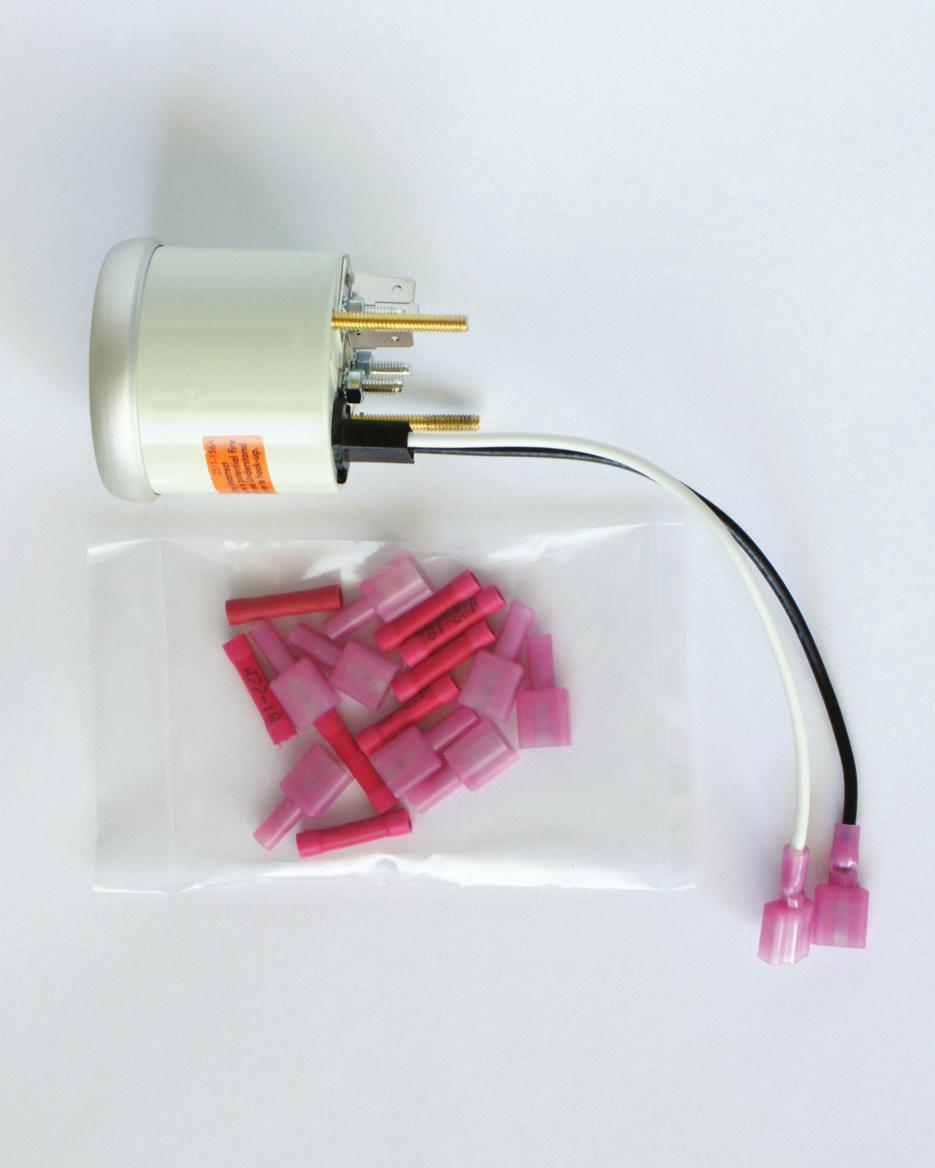
)&'((%1)'0*A,66-%5*%7)')$%2%+)EC,/$).(7F,/$ D%.G,(7,1.)'0*.(7)$%,00%*=%1),H%/0'5(7A,0%*B Step 1: Select an LED lamp from the panel, and attach the appropriate signal lead wire from the harness, as noted below.")
13 $%&'()%()*'+)$,*-./.0%+'0)$%1'((%1),'('+)$%23450( $%C%7D5))&'((%1)'0*A,66-%5*%7)')$%2%+)EC,/$).(7F,/$ D%.G,(7,1.)'0*.(7)$%,00%*=%1),H%/0'5(7A,0%*B Step 1: Select an LED lamp from the panel, and attach the appropriate signal lead wire from the harness, as noted below. Each signal wire will attach to the red LED lead wire from the panel. Trim the wires from the harness to the desired length before crimping. LED Color Function Power Wire Color Blue / Amber High Beam Red Green Left Turn Signal Orange Green Right Turn Signal White & Black Striped Red Parking Brake Tan Step 2: Install butt connectors, as shown, matching the wire functions noted above with the proper LED. Trim wires from the harness to the desired length before crimping. Match the black wire from each LED panel lamp with a black ground wire from the harness for all LED lamps except the red brake warning LED. If you are using the red brake warning LED lamp, remove the factory lamp socket and attach the black lead wire from this LED lamp to the factory brown wire. As noted above, the red will connect to the factory pink wire. /*8&5915$713:$ 13
6*,3,30-'77/*0)%*($,0%:*(4/8;%&'()*($<*,-4%0-'77/*0)*(,30 34%(0--*1,30=03*./0%0>'*%0-*,8 $%&'()*(+,-.,?270@A700)A0(-&%B?3*-*-49/4--*.")
14 connect to the factory pink wire. /*8&5915$713:$ $%&'()*($+*,*-*(./')0)1&%2&'%304)/*$3,56*70%-6*,.34() *$(*,*&(89&((0.,4--3&6(5%&',*($,&4$&&).34--*-$%&'()6*,3,30-'77/*0)%*($,0%:*(4/8;%&'()*($<*,-4%0-'77/*0)*(,30 34%(0--*1,30=03*./0%0>'*%0-*,8 A0()*($'(*,6*,3&',474--,3%&'$31&%.%'*-0.&(,%&/8?3*-6*// 6*//.&((0.,,&,30I&($E'%7/0D*%01&%,30A700)&:0,0%A*$(4/8 J/4.+D*%063*.36*//.&((0.,,&,30/&($K0//&6D*%063*.3*-4 ;%&'()*($D*%08?270FA700)A0(-&%B?3*-*-4',&L0,0%A,2/0A700)&:0,0% A0()*($'(*,6*,3474--,3%&'$31&%.%'*-0.&(,%&/8?3*-6*//34=0,3%006*%0-.&:*($&',&1*,8C0)D*%063*.36*//.&((0.,,&,30 J/4.+D*%063*.36*//.&((0.,,&,30/&($K0//&6D*%063*.3*-4 ;%&'()*($D*%08?270MA700)&:0,0%A0()*($N(*,B?3*-*-4',&L0,0%;EA A700)&:0,0%A0()*($'(*,8?3*-6*//34=0,3%006*%0-.&:*($&',&1 14


15 G&/,H$(*,*&(8D3*,0D*%063*.36*//.&((0.,,&,30I&($E'%7/0 D*%01&%,30A700)&:0,0%A*$(4/8J/4.+D*%063*.36*//.&((0.,,&,30/&($K0//&6D*%063*.3*-4;%&'()*($D*%08 /$0''-11%.-+2$3456(%*74.+,,1%2$4.%+62.8%+4'-+ %21%''+* **2-46--*6.-5+*%+6)-%+2-2$.1%, 9&(,*('0)&(,&(0O,74$08 15
= @&)2342/05,A **B9-&CD/-&)E*-/.9,8BB8,/*./.8FB899/75D.")
&-/.0/-*.<7-8O$0BD&P*%,/*.8BQ<8.")
16 $%&'(%&&)*+&,&-(&.)/.01./, $%&'()*+,-.(+ 7*-)B&99*-7*-)&))-/BB<=4-/BBI/,JK':L<F&.,&-%D.75*-/7&%/7M< N/-&7-/+%/.0,**B9*-89*B)&-/.0/-*.<7-8O$0BD&P*%,/*.8BQ<8.)8 +&89D-/.0,**B*E$*D-75*/7&A 16
17 (,&%=H 2*78,&,R*B*78,/*.9E*-,5&:;-&&.2342/05,9/0.8B/.)/78,*-9 8.)%-*7&&),*+8-M,5&B*78,/*.R/,5&/,5&-,5&7&.,&-%D.75*- /7&%/7MA4*,5/9*.,5&?87M*E,5&)895%8.&BA Step 2: Select a location for the Amber LED Light for the High Beam Indicator and an additional location for the Red LED Light for the Parking Brake Indicator and mark these locations with either the center punch or ice pick. Do this on the back of the dash panel. Step 3: Carefully drill the 4 holes you just located with the cordless or corded drill and the 5/32 drill bit. Step 4: Insert the 4 LED Lights in the holes drilled in step 3. You will need to insert the LED s from the front side of the dash panel. The LED s are barrel shaped so when you are inserting them make sure you get them fully seated all the way down. If you would like you may add a drop of crazy glue to the back of the LED housing on the back side of the panel after you fully seat the LED itself. Step 5: Select the Amber( High Beam) LED and attach it to the High Beam indicator wire in the wiring harness. Connect the Black lead to either a provided ground in the harness or a common ground of your choice. Step 6: Select the Left Green LED Light and attach the red lead from the LED to the Orange signal lead in your wiring harness. Connect the Black lead to either a provided ground in the harness or a common ground of your choice. Step 7: Select the Right Green LED Light and attach the red lead from the LED to the White and Black Striped signal lead in your wiring harness. Connect the Black lead to either a provided ground in the harness or a common ground of your choice. (,&%SH Select the Red (brake) LED and attach it to the long pink wire with a male and female spade connector in it. The Black Lead must be attached to a grounding circuit. Traditionally this is a dual connection. One connection is to the Emergency Brake Ground Switch. When the Emergency Brake is applied, the emergency brake switch sets the ground and will illuminate the light completing the electrical circuit. The Second side of the circuit is to the brake system equalization switch located in the brake fluid distribution manifold. If the Brake system equalization manifold senses an unequal pressure situation in the line, it sets a ground and will illuminate the Red Brake Led thus completing the electrical circuit. In the case of GM grounding circuits are through a Tan Wire at the emergency brake switch or the brake warning switch in the brake system distribution manifold. 17
'())&'*(1 ()*(*%&0/60&01(6)9-*+&5,/)9<-*%./0>?@8(6<-55'())&'**%& 0/60&5-0%*01(6)9()*(*%&+%(1*2A<-1&:$%&.")
18 $%&'()*$+,-.$/&)$0123$/*4&5615$713$ $ $%&'()*&)*+(,*%-+./0/1&,(1*%&234/55&1/67-5-/180/60&+ 5-0%*-)001(6)9+:;(6<-55=560*%&&)9<-*%/9(6.5&=-)'())&'*(1 ()*(*%&0/60&01(6)9-*+&5,/)9<-*%./0>?@8(6<-55'())&'**%& 0/60&5-0%*01(6)9()*(*%&+%(1*2A<-1&:$%&.5/'B<-1&-)*%& <-1-)0%/1)&++<-55=560()*(*%&+&'()9/18=-),1(4*%&9(6.5&=-) '())&'*(1: 18
19 89))64')3)*$:;1(*3145 C%&)6+-)0/*8=&(1*8=&?+=&&9(4&*&1+&)9-)06)-*D :C-*%*%&=(<&1(,,E=6+%/)9%(59*%&'/5-.1/*-().6**() F*1-=G1&+&*.6**()<%&)&H6-==&9I:C%-5&%(59-)0*%&.6**()E+*/1* *%&J&%-'5&/)9'()*-)6&*(%(59*%&.6**()6)*-5*%&=(-)*&1 +<&&=+*(,655+'/5&/)9+*/8+/*,655+'/5&:;(64/8)(<1&5&/+&*%&.6**():?:K1-J&*(*%&.&0-))-)0(,/=1&4/1B&9*<(4-5&+*1&*'%(,1(/9 F-&D/*(551(/9<-*%/''61/*&4-5&4/1B&1+I/)9'(4&*(/+*(=:L* 9(&+)M*4/**&1%(<,/1/</8*%&+*1&*'%(,1(/9-+:KNON$+%6*(,, *%&&)0-)&:P6+%*%&1&5&/+&.6**():$%&=(-)*&1<-5591(=*(%/5, 4/1B)(4/**&1<%/*+=&&98(6'%((+&*(91-J&*%&*<(4-5& +*1&*'%:L,*%&+=&&9(4&*&1%/+/)QRK9-+=5/8(9(4&*&1E-*<-55.& )(14/5*(+&&-*'(6)*-)01/=-958/+-*-+1&'&-J-)0/+=&&9+-0)/5:L, 8(6%/J&*(+*(=961-)0*%&'/5-.1/*-()*%/*-+(B:$%&+=&&9(4&*& =58'(6)*-)0=65+&+961-)0*%-+*-4&: 2:S**%&&)9(,*%&*<(4-5&9-+*/)'&E'(4&*(/'(4=5&*&+*(=E =6+%/)91&5&/+&*%&.6**():$%&=(-)*&1<-5591(=*(/)9*%& '/5-.1/*-()<-55.&+*(1&9: 9()(*%/J&*('/5-.1/*&-**(/$%6)9&1V(/9(1S6*(W&*&1X5&'*1-' 3=&&9(4&*&1U/60&1&H6-1-)0/YEPPWR/5-.1/*-()V/*-)0:L,,(1+(4&1&/+()8(61+=&&9(4&*&11&H6-1&+/9-,,&1&)*1/*-)0*%-+-+ %(<*('/5-.1/*&-*D :C-*%*%&+=&&9(4&*&1'())&'*&9/)9=(<&1&9E=1&++/)9%(59 *%&'/5-.1/*-().6**()()*%&*(=(,*%&4(965&:$%&)&&95&<-55.&0-)*('5-4.:S*,-1+*E-*<-554(J&J&18+5(<58.6*<-55=-'B6= +=&&9*%&5()0&1*%&.6**()-+%&59: 19
'B(,+/*((&'5'.E5)(F&3(,+01++.&2+(+3(& 3+(*3'(&:;<=6(,)00,&*-.,511+')'5/&*(@0+4&'.08$<3&1+3 45-)/35()&'5'.B5*B+544*354A53+.+1+'.+'(&'(,+'++.")
20 $%&'()'*+(&,&-.(,+/*((&'*'()-(,+01++.&2+(+3)'.)45(+0 4-&0+(&6/*('&(&7+389:;<=5' (,+/*((&'$ 3+5.)'B*'()-(,+01++.&2+(+3)'.)45(+0+C54(-A9:;<=$?,+' 3+54,+.D0(&113+00)'B(,+/*((&'5'.E5)(F&3(,+01++.&2+(+3(& 45-)/35()&'5'.B5*B+544*354A '.+'(&'(,+' ,)'B13+4)0+-A9:;<=$ G$HFA&*B&150(9:;<=D0(&113+00)'B(,+/*((&'5'.E5)(F&3(,+ 0+4&'.0$J(+10K>0,&*-.(,+'/+3+1+5(+.$ $%&$''()*+,-.+/0')1)234,3)54-6)%%7)42* '*+,-6)&.'4%%$8,62) %:46)'; J6)+=+,-462*1)86$8$46%&$''()4(')1+)'0*+,; K$/$141$+6+=K$4($'$1*LL&(,++C(+'(5--&E5/-+*' )45/-+-5ED %-500)4M*(&2&()7+J1+4)5-()+0-)5/)-)(AF&34&'0+N*+'()5-5'. )'4).+'(5-.525B+0)0+C13+00-A.)04-5)2+.$%-500)4M*(&2&()7+ J1+4)5-()+0-)5/)-)(A)'5--+7+'(0)0-)2)(+.(&5'.0,5--'&(+C4++.(,+ 1*34,50+13)4+15).$ Connect with the factory toll-free
Camaro Camaro
 Important facts about this kit. 1. The dash panel used in this picture is used by permission of Covan's Classic. We Make Wiring Easy! 2. This kit requires some modification to your original under dash
UNIVERSAL GAUGE WIRE HARNESS
 2650-1797-00 UNIVERSAL GAUGE WIRE HARNESS For Installing Auto Meter Electric Speedometer, Tachometer, And Short Sweep Electric Oil Pressure, Water Temperature, Fuel Level, and Volt Meter Gauges. This harness
Rear Body 40D 156A 24 17A 151 3D. 8A,8B,8C under hood light. Horn Relay 91
 fuse box as viewed from the wire entry side Mating connector is plugged into Power Accessory connector 40D Rear Body 19 18 9B 30 LH Courtesy Light 40A,D 4D, 43 156B,C 16 16A 4C 3D 3C 16A 3G 4B 3G 116 4A&130
Chevy INSTRUMENT CLUSTER CONNECTION KIT WIRING INFORMATION FOR A STOCK CHEVY CLUSTER GREY PINK S + FUEL TEMP S + LAMP LAMP HI BEAM
 WIRING INFORMATION FOR A STOCK 1955-56 CEVY CLUSTER 1955-56 Chevy Terminals and connectors are provided for installation to a stock 1955-56 dash cluster. Pigtail connections are provided for the instrument
Instrument Cluster 30 33B 39B A B C D E F E F G H J. Connector. Circuit Branch #4. Circuit Branch #5. Circuit. Branch #6 150A. Ground.
 16 4D, 43 4B 4A & 130 100 50 39A,B,C 300 4C 4B 4C 107 3C 3D 3C 3G 3B 3F 3A 16A 3G 116 104 93 3B 3D 2E 16A 2C 2D 2B 2A 44 40 27A 40B 115 27 40A,C,E 8A,B,C Mating is plugged into accessory connector Power
INTERFACE PART NUMBER NOTES
 2000 Saturn S-Series ALARM REMOTE START WIRING WIRE COLOR LOCATION 12V CONSTANT RED Ignition Harness STARTER YELLOW Ignition Harness IGNITION PINK Ignition Harness ACCESSORY ORANGE Ignition Harness SECOND
UNIVERSAL WIRING HARNESS Installation Manual
 UNIVERSAL WIRING HARNESS Installation Manual Terminals are provided for most connections on your wiring kit. Following the gauge manufacturer s instructions, use the terminals supplied with your gauge
Classic Update Series
 *** These are special instructions for connecting your wiring system to a stock instrument cluster. *** NOT: If you are using after market gauges, follow the instructions included in the 92965220 Gauge
jegs.com
 Contents Wiring Harness w/ Fuse Panel Installation Instructions Turn Signal Plug w/ Terminals 2 Headlight Plugs 3/4 Grommet 10 ¼ Terminals 4 Ring Terminals 10 Wire Ties Fusible Link 2 Screws & Nuts 2 Plastic
Replace light bulb with the same number bulb as the one removed. White Wire: Connect to +12 Volt Lighting
 INSTALLATION INSTRUCTIONS SHORT SWEEP ELECTRIC GAUGES 2650-1079-00 Rev. C CAUTION FOR ALL GAUGE INSTALLATION (AMMETERS EXCLUDED) As a safety precaution, the +12V wire attached to the positive I (+) terminal
INSTRUCTIONS. 20 Circuit Wiring Kit Instructions October 2009, Speedway Motors, Inc.
 1 MAIN FUSE PANEL The main fuse panel harness s designed to be mounted under the dash a the firewall in an area close to the steering column. The enclosed representation of the main dash harness shows
Classic Update Series
 lassic Update eries FOR 1967-69 APPLIATION TI AAW KIT O NOT UPPORT T U OF A FATORY AMMTR. A A RPLAMNT FOR T AMMTR W UGGT T U OF A VOLTMTR INTA. TRMINAL KIT 92965220 A BN PROVI FOR YOU TO ONNT TI LUTR KIT
Classic Update Series
 J Clamps Two J-Clamps have been provided to retain the Cluster Kit Wiring in place (see photographs on pages 7 and ). Remove the original J-Clamps from the Cluster and replace with the two J-Clamps item
Replace light bulb with the same number bulb as the one removed. White Wire: Connect to +12 Volt Lighting
 INSTALLATION INSTRUCTIONS SHORT SWEEP ELECTRIC GAUGES 2650-1079-00 Rev. C CAUTION FOR ALL GAUGE INSTALLATION (AMMETERS EXCLUDED) As a safety precaution, the +12V wire attached to the positive I (+) terminal
Mustang Classic Update Series Kit
 accessory rear body 19 9 11 instrument cluster and map 10A, 0 4 3 7 40G 18 30 17A 24 1A 14A 9C 8A instrument cluster 4E 31 3 121 11 401 10A 3 400 30 washer and wiper switch 93A, 93 glovebox, map light,
Installation Manual v1.0: Code Blocker Electronics Kit GM LBZ Duramax. Please read all instructions before installation.
 Installation Manual v1.0: Code Blocker Electronics Kit 2006-07 GM LBZ Duramax Please read all instructions before installation. 1. Mount the electronics package on the grill support as shown. Use the self-tapping
Classic Update Series
 Classic Update Series 1964-1966 Ford Mustang START HERE! PLEASE READ THIS EFORE STARTING INSTALLATION! This wiring kit is designed for ease of installation. Please read the guidelines below, EFORE STARTING
Classic Update Series
 page 1 *** These are special instructions for connecting your wiring system to a stock instrument cluster. *** NOTE: f you are using after market gauges, follow the instructions included in the 92965220
 510564 OPYRIGHT 2013 American Autowire / Factory-Fit Used with express permission of American Autowire / Factory- Fit Page 1 92971174 Rev 0.0 6/18/2015 UNSEALED ONNETORS The connectors, sockets, wires,
Classic Update Series
 START HERE! PLEASE READ THIS BEFORE STARTING INSTALLATION! This wiring kit is designed for ease of installation. Please read the guidelines below, BEFORE STARTING your installation to guarantee a successful
CLASSIC UPDATE WIRING KIT
 by Randy Irwin 1955-57 CLASSIC UPDATE WIRING KIT Randy Irwin - Technical Writer Randy has been involved in the Chevy parts business for over 25 years. He is a wizard at creating, making and modifying custom
Step 1 : Starting the installation
 Installation Instructions for GM Remote Start w/ INTSL Interface Pre-wired Review the remote start installation manual for safety instructions! Overview Your kit consists of two modules a remote start
Optional Wiring. This section deals with some of the optional wiring that may be needed depending on how you choose to construct your car.
 CHAPTER 23 Optional Wiring This section deals with some of the optional wiring that may be needed depending on how you choose to construct your car. OEM Tail light connections to Fiero harness The following
TELORVEK II RJ-32 Big Block RamJet Fuel Injection System
 Page #1 TELORVEK II RJ-32 Big Block RamJet Fuel Injection System This wiring system is compatible with the GM Performance part big block Ramjet 502 engine. The harness is designed to dress up the appearance
Ford Econoline
 Guardian Lift Interlock (GRD0-BB) Installation Instructions Ford Econoline 009-00 It is not necessary to cut any Ford wires during the installation of the Guardian wire harnesses. Always disconnect the
ISIS Power Manual and Installation Guide Race Car Replicas- Superlite Coupe
 ISIS Power Manual and Installation Guide Race Car Replicas- Superlite Coupe Table of Contents Overview... 2 System Details... 3 Kit Includes... 3 Technical Specifications... 3 Harness Descriptions... 4
Classic Update Series
 Classic Update Series 67-72 Ford Truck START HERE! PLEASE READ THIS EFORE STARTING INSTALLATION! This wiring kit is designed for ease of installation. Please read the guidelines below, EFORE STARTING your
Classic Update Series
 Classic Update Series *** These are special for connecting your wiring system to a stock instrument cluster. *** (Note: This kit does not support the use of a stock ammeter.) REFER TO THE TTCHED DIGRMS
WIRING DIAGRAM AND INSTALLATION INSTRUCTIONS
 WIRING DIAGRAM AND INSTALLATION INSTRUCTIONS FOR 99101307 ADAPTER KIT Sno-Way, Down Pressure and EIS are registered trademarks of Sno-Way International, Inc. ProControl, MegaBlade, V-Wing, E-Z Switch,
Repair harness. Repair Harnesses
 Repair harness Repair Harnesses Truck side repair harness (2 plugs) 53632-B......2 Truck side repair harness (1 plug) 53470-02-B..4 MPX truck side repair controller harness 53625-MPX....5 MPX truck side
HYFIRE 6.6 SERIES OF ELECTRONIC IGNITION CONTROL
 FORM 1486M 03/05 INSTALLATION INSTRUCTIONS HYFIRE 6.6 SERIES OF ELECTRONIC IGNITION CONTROL HYFIRE 6.6 IGNITION SYSTEM PART NO. 686M FOR APPLICATIONS TRIGGERED BY POINTS, MALLORY ELECTRONIC IGNITION DISTRIBUTOR
LSx Harness Installation. lsxeverything.com #BecauseYouShould
 LSx Harness Installation lsxeverything.com #BecauseYouShould Table of Contents Slide 1 Introduction Page Slide 2 Table of Contents Slide 3 Starting Instructions Slide 4 Power Connections Slide 5 Ground
accessory connection rear body connection 40G 17A instrument cluster and map lamp ground 150A,B 15A 14A Circuit Branch 500A fog lamp switch
 accessory rear body 19 9 11 instrument cluster and map 10A, 0 4 3 7 40G 18 30 17A 24 1A 14A 9 8A instrument cluster 4E 31 3 121 11 33 401 10A 39A 400 30 washer and wiper switch 93A, 94 93 glovebox, map
72 Mustang Mach 1 tachometer cluster and gauge conversion
 72 Mustang Mach 1 tachometer cluster and gauge conversion Dated: 02-17-2009 (drafted by a Chevy person working on his first Ford -not good-) Revised: 11-05-2010 The following information pertains to how
Classic Update Series
 Classic Update Series *** These are special for connecting your wiring system to a stock instrument cluster. *** (Note: This kit does not support the use of a stock ammeter.) REFER TO THE TTCHED DIGRMS
Classic Update Series
 Classic Update Series 62-65 Ford Fairlane and 62-63 Mercury Meteor end view of terminal START HERE! PLEASE READ THIS EFORE STARTING INSTALLATION! This wiring kit is designed for ease of installation. Please
Classic Update Series
 Classic Update Series 73-79 Ford F100-350 & 78-9 Ford ronco START HERE! PLEASE READ THIS EFORE STARTING INSTALLATION! This wiring kit is designed for ease of installation. Please read the guidelines below,
INSTALLATION INSTRUCTIONS
 Rear Vision System NAV Display 2009-Current Chevrolet Silverado, Silverado HD; GMC Sierra, Sierra HD (Kit part number 9002-9501) Kit Contents: Camera/Module/Bezel Assembly Chassis Harness NAV Harness 1
DASH/MAIN HARNESS. NOTE: wires 400 & 401, must be twisted together.
 Electric Speedo Ground 151 Turn Flasher 16A 4 150 8A, Cluster Connections 31 33 30 35 151 (electric speedo) 402 401 NOTE: wires 400 & 401, must be twisted together. 156D, E Panel Dimmer 8A 9, C 2D Headlight
Instructions for installing Extendable Replacement Mirrors for Ford HD vehicle.
 Instructions for installing Extendable Replacement Mirrors for Ford HD vehicle. Manual CIPA # 82100 Right Hand #82110 Left Hand #82111 Electric CIPA # 72100 #72110 #72111 Heated / Electric CIPA # 72500
SITRANS F flowmeters. SITRANS F O delta p - Primary differential pressure devices. Orifice plate with annular chambers. 4/358 Siemens FI
 Application Dimensional drawings Suitable for non-corrosive and corrosive gases, vapors and liquids; permissible operating temperature -60 to +550 C. Design Two support rings with replaceable orifice disk
Classic Update Series
 Classic Update Series *** These are special for connecting your wiring system to a stock instrument cluster. *** (Note: This kit does not support the use of a stock ammeter.) REFER TO THE TTCHED DIGRMS
FROG-D 3P. FREQUENCY READOUT OF GENERATOR THREE PHASE GENERATOR DISPLAY MODELS: FDA700 for Delta Winding FDA710 for Star Winding
 Document Number: XE-FDA7PM-R0A FDA700 Rev160509 FROG-D 3P FREQUENCY READOUT OF GENERATOR THREE PHASE GENERATOR DISPLAY MODELS: FDA700 for Delta Winding FDA710 for Star Winding FIRE RESEARCH CORPORATION
Installation Tips for your Crimestopper/ProStart Remote Start system (add-on for GM vehicles) v1.02 updated 1/16/2013
 v1.02 updated 1/16/2013") Installation Tips for your Crimestopper/ProStart Remote Start system (add-on for GM vehicles) v1.02 updated 1/16/2013 Thank you for purchasing your remote start from MyPushcart.com - an industry leader
Installation Tips for your Crimestopper/ProStart Remote Start system (add-on for GM vehicles) v1.02 updated 1/16/2013 Thank you for purchasing your remote start from MyPushcart.com - an industry leader
Installation Tips for your Add-on Remote Start (for GM vehicles with INTSL Install 2) v3.2 Updated 11/12/2012
 v3.2 Updated 11/12/2012") Installation Tips for your Add-on Remote Start (for GM vehicles with INTSL Install 2) v3.2 Updated 11/12/2012 Thank you for purchasing your remote start from MyPushcart.com - an industry leader in providing
Installation Tips for your Add-on Remote Start (for GM vehicles with INTSL Install 2) v3.2 Updated 11/12/2012 Thank you for purchasing your remote start from MyPushcart.com - an industry leader in providing
DP10001 UNIVERSAL 5 GAUGE DIGITAL PANEL
 Nordskog Performance Products DP10001 UNIVERSAL 5 GAUGE DIGITAL PANEL **Before beginning the installation, read through these instructions thoroughly. Also, disconnect the positive battery cable to avoid
INSTALLATION INSTRUCTIONS
 Rear Vision System Aftermarket Display 2007-Current Chevrolet Silverado, Silverado HD; GMC Sierra, Sierra HD (Kit part number 9002-9560) Kit Contents: Chassis Harness with RCA (Note: In some cases a RCA
WIRE HARNESS INSTALLATION INSTRUCTIONS. For Installing: Part # Circuit Universal CJ Jeep Harness ( ) Manual #90513
 Manual #90513") WIRE HARNESS INSTALLATION INSTRUCTIONS For Installing: Part #10110 12 Circuit Universal CJ Jeep Harness (1975-86) Manual #90513 Perfect Performance Products, LLC Painless Performance Division 2501 Ludelle
WIRE HARNESS INSTALLATION INSTRUCTIONS For Installing: Part #10110 12 Circuit Universal CJ Jeep Harness (1975-86) Manual #90513 Perfect Performance Products, LLC Painless Performance Division 2501 Ludelle
Classic Update Series
 Classic Update Series START HERE! PLEASE READ THIS EFORE STARTING INSTALLATION! This wiring kit is designed for ease of installation. Please read the guidelines below, EFORE STARTING your installation
INSTALLATION INSTRUCTIONS
 Rear Vision System Aftermarket Display 2007-Current Chevrolet Silverado, Silverado HD; GMC Sierra, Sierra HD (Kit part number 9002-9560) Kit Contents: Camera/Module/Bezel Assembly Chassis Harness with
WIRING DIAGRAM AND INSTALLATION INSTRUCTIONS
 WIRING DIAGRAM AND INSTALLATION INSTRUCTIONS FOR 99075 ADAPTER KIT Sno-Way, Down Pressure and EIS are registered trademarks of Sno-Way International, Inc. ProControl, MegaBlade, V-Wing, E-Z Switch, Revolution,
Installation Instructions
 Installation Instructions Jeep JK 2-Door (2011 Present) Mounting Bracket and Air Line System Kit for ARB On-Board Twin Air Compressor (CKMTA12) Made in the USA Kit Contents: 1 Flat Bracket 1 Formed Bracket
INSTRUCTIONS 12 Circuit Wiring Kit Instructions
 Fan 47 9 56 4 7 6 72 40 45 48 5 8 6 Gauge Power Temp Sender Headlight Power Power Radio Constant Power Instruments and Dash Rear of Vehicle Ignition and Lights Fuse Panel & Front of Vehicle Horn Alt Excitor
Intelligent Lift Interlock System (ILIS) Installation Instructions
 Installation Instructions") Intelligent Lift Interlock System (ILIS) Installation Instructions Part No: ILIS602-G 2000 2005 Chevrolet Venture Mini-Van To aid in installation, first gain access to the connection points. Remove the
Intelligent Lift Interlock System (ILIS) Installation Instructions Part No: ILIS602-G 2000 2005 Chevrolet Venture Mini-Van To aid in installation, first gain access to the connection points. Remove the
Quick Reference for International CF Series Electrical Circuit Diagrams
 Quick Reference for International CF Series Electrical Circuit Diagrams A N AV I S TA R C O M PA N Y Electrical Symbols Distributed splice Component with screw terminals Solenoid controlled valve or clutch
Bucket Harness. Installation Instructions. for Electric Club Car Precedent
 Bucket Harness for Electric Club Car Precedent Installation Instructions Electric Club Car Precedents manufactured after January 1, 2008 require an additional harness to allow the installation of light
TTR225/250 DUAL S PORT K IT I NSTALLATION I NSTRUCTIONS
 TTR225/250 DUAL S PORT K IT I NSTALLATION I NSTRUCTIONS KIT CONTENTS Inspect Your Kit Your kit will include the following items A. TTR225/250 Instructions and Wiring Diagrams Read through the entire instruction
Installation Tips for your Remote Start/Keyless Entry (for Ford Vehicles) v3.3 Updated 1/13/2013
 v3.3 Updated 1/13/2013") Installation Tips for your Remote Start/Keyless Entry (for Ford Vehicles) v3.3 Updated 1/13/2013 Thank you for purchasing your remote start from MyPushcart.com - an industry leader in providing remote
Installation Tips for your Remote Start/Keyless Entry (for Ford Vehicles) v3.3 Updated 1/13/2013 Thank you for purchasing your remote start from MyPushcart.com - an industry leader in providing remote
Installation Tips for your GMDLBP + Excalibur Remote Start system (for GM vehicles) v1.01 updated 10/09/13
 v1.01 updated 10/09/13") Installation Tips for your GMDLBP + Excalibur Remote Start system (for GM vehicles) v1.01 updated 10/09/13 Thank you for purchasing your remote start from MyPushcart.com - an industry leader in providing
Installation Tips for your GMDLBP + Excalibur Remote Start system (for GM vehicles) v1.01 updated 10/09/13 Thank you for purchasing your remote start from MyPushcart.com - an industry leader in providing
Classic Update Series
 Classic Update Series *** These are special for connecting your wiring system to a stock instrument cluster. *** (Note: This kit does not support the use of a stock ammeter.) REFER TO THE TTCHED DIGRMS
WIRING DIAGRAM AND INSTALLATION INSTRUCTIONS
 WIRING DIAGRAM AND INSTALLATION INSTRUCTIONS FOR 99101361 ADAPTER KIT Sno-Way, Down Pressure and EIS are registered trademarks of Sno-Way International, Inc. ProControl, MegaBlade, V-Wing, E-Z Switch,
INSTRUCTIONS Circuit Wiring Kit Instructions _2017. Fuse Box Connections. (viewed from underside) 2018, Speedway Motors, Inc.
 2018, Speedway Motors, Inc.") Fuse Box Connections (viewed from underside) 4D 4C 100 50 300 4D 4C 4B 4A 43 107 39 103 3B 2G 104 93 2F 2E 2D 2C 2B 40 69A 102 101 105 2G 2F 2E 3A A 2A B 40A,B 27 69A 106 201, Speedway Motors, Inc. 1 Fuse
Fuse Box Connections (viewed from underside) 4D 4C 100 50 300 4D 4C 4B 4A 43 107 39 103 3B 2G 104 93 2F 2E 2D 2C 2B 40 69A 102 101 105 2G 2F 2E 3A A 2A B 40A,B 27 69A 106 201, Speedway Motors, Inc. 1 Fuse
Electrical. Hardware & Fastening Solutions. Battery Supplies. J-Case Fuses - Regular... Page 162
 Flag Style... Page 156 Electrical Batteries... Page 153 Mounting Pads (Adhesive Backed)... Page 161 Battery Supplies J-Case Fuses - Regular... Page 162 Booster Cable Supplies... Page 153 J-Case Fuses -
BOM507-BC Black Out Module 2017 Ford F250-F550 Contact InterMotive for additional applications
 An ISO 9001:2008 Registered Company BOM507-BC Black Out Module 2017 Ford F250-F550 Contact InterMotive for additional applications Introduction The BOM507-BC module has the ability to eliminate all exterior
Rear Vision System Tailgate Emblem Camera Aftermarket Display 2009-Current Ford F-150 and 2010-Current Super Duty (Kit part number )
") Rear Vision System Tailgate Emblem Camera Aftermarket Display 2009-Current Ford F-150 and 2010-Current Super Duty (Kit part number 1008-6509) Kit Contents: Tailgate Emblem Mount with Camera Chassis Harness
Rear Vision System Tailgate Emblem Camera Aftermarket Display 2009-Current Ford F-150 and 2010-Current Super Duty (Kit part number 1008-6509) Kit Contents: Tailgate Emblem Mount with Camera Chassis Harness
Installation Tips for your Remote Start system (for RS4LX>GMBP for GM vehicles)
") Installation Tips for your Remote Start system (for RS4LX>GMBP for GM vehicles) Thank you for purchasing your remote start from MyPushcart.com - an industry leader in providing remote starts to doit-yourself
Installation Tips for your Remote Start system (for RS4LX>GMBP for GM vehicles) Thank you for purchasing your remote start from MyPushcart.com - an industry leader in providing remote starts to doit-yourself
30140 F5 Dual Fan Controller
 30140 F5 Dual Fan Controller 1 2501 Ludelle Street Fort Worth, Texas 76105 817-244-6212 Phone 817-244-4024 Fax 888-350-6588 Sales 800-423-9696 Tech E-mail: painless@painlessperformance.com Web: www.painlessperformance.com
Intelligent Lift Interlock ILISCT511-A (Manual Lift Door) Ford Transit Connect
 Ford Transit Connect") An ISO 9001:2000 Registered Company Intelligent Lift Interlock ILISCT511-A (Manual Lift Door) 2010-2013 Ford Transit Connect Introduction The ILISCT511 is a microprocessor driven system for controlling
An ISO 9001:2000 Registered Company Intelligent Lift Interlock ILISCT511-A (Manual Lift Door) 2010-2013 Ford Transit Connect Introduction The ILISCT511 is a microprocessor driven system for controlling
Classic Update Series
 Classic Update Series 0-4 Ford Falcon and 0- Mercury Comet end view of terminal START HERE! PLEASE READ THIS EFORE STARTING INSTALLATION! This wiring kit is designed for ease of installation. Please read
Installation Tips for your Excalibur Remote Start (for Honda and Acura Vehicles) rev 11/28/2012
 rev 11/28/2012") Installation Tips for your Excalibur Remote Start (for Honda and Acura Vehicles) rev 11/28/2012 Thank you for purchasing your remote start from MyPushcart.com - an industry leader in providing remote starts
Installation Tips for your Excalibur Remote Start (for Honda and Acura Vehicles) rev 11/28/2012 Thank you for purchasing your remote start from MyPushcart.com - an industry leader in providing remote starts
40A A 40B. Horn Relay Connector. Brake Switch. Third Brake Light. Brake Switch. Brake Switch. Wires. page 3. Rear Body Feed Wires.
 Fuse Box Connections (viewed from underside) 4D 4C 4D 0 50 300 4C 43 7 39 3 6 4 93 A 2G 2F 2E 2D 2C 2B 2G 2F 2E 40 69A 2 1 5 27 69A 3A B 40A,B 11A,B 40A 156 Dimmer Dome Feed page 2 Horn Relay 2D 2 29 40B
Chevy Equinox / GMC Terrain 2013-up (with color display) G
 G") INSTALLATION INSTRUCTIONS FOR PART 99-3308G Chevy Equinox / GMC Terrain 2013-up (with color display) 99-3308G KIT FEATURES ISO DIN radio provision with pocket ISO DDIN radio provision Painted gray to match
INSTALLATION INSTRUCTIONS FOR PART 99-3308G Chevy Equinox / GMC Terrain 2013-up (with color display) 99-3308G KIT FEATURES ISO DIN radio provision with pocket ISO DDIN radio provision Painted gray to match
Classic Update Series
 J lassic pdate eries page 1 www.americanautowire.com 56-9-001 J lamp Two J-lamps (item T on this page) have been provided to retain the luster it iring in place (see photographs on pages 5 and 6). plice
Installation Instructions - ECS Tuning Vent Pod Vacuum/Boost Gauge Kit
 Installation Instructions - ECS Tuning Vent Pod Vacuum/Boost Gauge Kit This tutorial is provided as a courtesy by ECS Tuning. Part Number for Audi B6 A4 (2002-2004) Proper service and repair procedures
Pantera Electronics LED Taillight Installation Manual
 Pantera Electronics LED Taillight Installation Manual (2nd Gen) This LED signal lamp conversion was designed to replace the incandescent lamp 1157 with a Light Emitting Diode Array designed specifically
1963 GEN IV SUREFIT VINTAGE AIR CONDITIONING INSTALLATION
 by Randy Irwin 1963 GEN IV SUREFIT VINTAGE AIR CONDITIONING INSTALLATION Randy Irwin - Technical Writer Randy has been involved in the Chevy parts business for over 30 years. He is a wizard at creating,
-----
 ----- - - -- - - -- - -- - - NOTE: #32 WIRE DOES NOT APPLY TO 8 AND 14 CIRCUIT HARNESSES ELECTRIC FAN #1 TO FAN SWITCH (GRAY) #21 TEMP. GAUGE (GREEN) #2 TO AC SWITCH (BLACK) JUMPER WIRE ALTERNATORS
Classic Update Series
 Classic Update eries 1966-1977 Ford Bronco TART HERE! We carry many accessories for your p/n 500649 OEM small terminal crimping tool (18-14 gauge) p/n 500523 OEM large terminal crimping tool (12-8 gauge)
INSTALLATION INSTRUCTIONS. Rear Vision System Aftermarket Display 2009-Current Dodge Ram (Kit part number )
") Rear Vision System Aftermarket Display 2009-Current Dodge Ram (Kit part number 1009-6503) Kit Contents: Chassis Harness with RCA Endgate Handle with Camera 1 bag containing: Wire Ties (Qty: 17) Bottle
Rear Vision System Aftermarket Display 2009-Current Dodge Ram (Kit part number 1009-6503) Kit Contents: Chassis Harness with RCA Endgate Handle with Camera 1 bag containing: Wire Ties (Qty: 17) Bottle
ATTENTION. Custom Dynamics UTV Turn Signal Kit Installation Instructions
 Custom Dynamics UTV Kit Installation Instructions We thank you for purchasing the Custom Dynamics UTV LED Kit. Our products utilize the latest technology and high quality components to ensure you the most
X-Charge Fitting Instructions
 X-Eng is a division of Foundry 4x4 Limited The Old Bakery, Rear of Vale Terrace, Tredegar, Gwent. NP22 4HT X-Charge Fitting Instructions Thank you for choosing to buy an X-Charge! Vehicle newer than 1995
INSTALLATION INSTRUCTIONS
 OEM Lip Mount Camera with Harness and OnStar Mirror for GM Vehicles with 10-pin Mirror Connector (Kit part number 9002-8723) Items Included in the Kit: Bubble bag containing: Camera with Mount Mirror Mirror
Installation Instructions - ECS Tuning Vent Pod Vacuum/Boost Gauge Kit
 Installation Instructions - ECS Tuning Vent Pod Vacuum/Boost Gauge Kit This tutorial is provided as a courtesy by ECS Tuning. Part Number for (2005-2008) Proper service and repair procedures are vital
Installation Instructions
 Installation Instructions Jeep JK Unlimited (2007 Present) Mounting Bracket and Air Line System Kit for ARB On-Board Twin Air Compressor (CKMTA12) Made in the USA Kit Contents: 1 Bracket for ARB Compressor
Installation Items: Cruise Module
 Installation Items: Rostra 250-1223, Electronic Cruise Control System (ECCS) includes the cruise module, harness, cruise cable, cruise module mounting bracket, cruise cable mounting bracket and hardware
INSTALLATION INSTRUCTIONS
 Rear Vision System Tailgate Emblem Camera Aftermarket Display 2009-Current Ford F-150 and 2010-Current Super Duty (Kit part number 1008-6509) Kit Contents: Tailgate Emblem Mount with Camera Chassis Harness
8436, 8437, 8438, 8439, 8442, 27480, 27780, 28028, & ISOLATION MODULE ELECTRICAL SYSTEM
 September 11, 2003 Lit. No. 27808 8436, 8437, 8438, 8439, 8442, 27480, 27780, 28028, & 28400 ISOLATION MODULE ELECTRICAL SYSTEM Installation Instructions Read this document before installing the snowplow.
Installation Tips for your Crimestopper/ProStart Remote Start system (for GM vehicles) v1.01 updated 2/27/2012
 v1.01 updated 2/27/2012") Installation Tips for your Crimestopper/ProStart Remote Start system (for GM vehicles) v1.01 updated 2/27/2012 Thank you for purchasing your remote start from MyPushcart.com - an industry leader in providing
Installation Tips for your Crimestopper/ProStart Remote Start system (for GM vehicles) v1.01 updated 2/27/2012 Thank you for purchasing your remote start from MyPushcart.com - an industry leader in providing
INSTALLATION INSTRUCTIONS FORD POWERSTROKE PICKUPS MODEL YEAR
 p p INSTALLATION INSTRUCTIONS FORD POWERSTROKE PICKUPS MODEL YEAR 2005-2006 www.dieselturbolifesaver.com Diesel Turbo Lifesaver (DTLS) is a computer controlled device that allows you to set an automatic
ADDICTIVE DESERT DESIGNS
 Preparation: Disconnect the negative battery terminal. Park the vehicle on level ground and set the emergency brake. We recommend reading through the installation instructions in whole before performing
2004 Scion xa. PARKING LIGHTS (+) GREEN At Harness On Top Of Fuse Box DOOR TRIGGER (-) RED/WHITE In 9-Pin On Top Of Fuse Box
 GREEN At Harness On Top Of Fuse Box DOOR TRIGGER (-) RED/WHITE In 9-Pin On Top Of Fuse Box") ALARM REMOTE START WIRING WIRE COLOR LOCATION 12V CONSTANT WIRE WHITE/BLUE and Ignition Harness WHITE/RED STARTER WIRE BLACK Ignition Harness 12V IGNITION WIRE BLACK/RED Ignition Harness SECOND IGNITION
ALARM REMOTE START WIRING WIRE COLOR LOCATION 12V CONSTANT WIRE WHITE/BLUE and Ignition Harness WHITE/RED STARTER WIRE BLACK Ignition Harness 12V IGNITION WIRE BLACK/RED Ignition Harness SECOND IGNITION
Installation Tips Crimestopper/ProStart Remote Start system + PLJX + DLRM + SPDT (for GM vehicles) T0760 v1.1 updated 2/5/14
 T0760 v1.1 updated 2/5/14") Installation Tips Crimestopper/ProStart Remote Start system + PLJX + DLRM + SPDT (for GM vehicles) T0760 v1.1 updated 2/5/14 Thank you for purchasing your remote start from MyPushcart.com - an industry
Installation Tips Crimestopper/ProStart Remote Start system + PLJX + DLRM + SPDT (for GM vehicles) T0760 v1.1 updated 2/5/14 Thank you for purchasing your remote start from MyPushcart.com - an industry
SCION xb QUARTER GARNISH NET Preparation
 Preparation Part Number: 08446-12800 (Light Gray) Part number of this accessory may not be the same as the part number shown. Kit Contents 1 1 Quarter Garnish Net RH 2 1 Quarter Garnish Net LH 3 8 Cap
SUM EFI Wiring Harness for GM LT-1/LT-4 Engine INSTALLATION INSTRUCTIONS
 SUM-890121 EFI Wiring Harness for GM LT-1/LT-4 Engine INSTALLATION INSTRUCTIONS INTRODUCTION This harness is designed for GM 1992-97 LT1/LT4 fuel injected engines. Even with minimal electrical experience,
TIP SHEET. Installation Tips for your RS OL-MDB-CH6 (1) (for Jeep vehicles) T1227 v1.0 3/19/14
 (for Jeep vehicles) T1227 v1.0 3/19/14") TIP SHEET Installation Tips for your RS-360 + OL-MDB-CH6 (1) (for Jeep vehicles) T1227 v1.0 3/19/14 Thank you for purchasing your remote start from MyPushcart.com - an industry leader in providing remote
TIP SHEET Installation Tips for your RS-360 + OL-MDB-CH6 (1) (for Jeep vehicles) T1227 v1.0 3/19/14 Thank you for purchasing your remote start from MyPushcart.com - an industry leader in providing remote
OEM Lip Mount Camera with Harness and OnStar Mirror for GM Vehicles with 16-pin Mirror Connector (Kit part number )
") OEM Lip Mount Camera with Harness and OnStar Mirror for GM Vehicles with 16-pin Mirror Connector (Kit part number 9002-8722) Please read thoroughly before starting installation and check that kit contents
OEM Lip Mount Camera with Harness and OnStar Mirror for GM Vehicles with 16-pin Mirror Connector (Kit part number 9002-8722) Please read thoroughly before starting installation and check that kit contents
Copyright Triple S Customs
 CADILLAC CONCOURS 1994-1997 VEHICLE WIRING Copyright 2002-2004 Triple S Customs WIRING INFORMATION: 1994 Cadillac Concours 12V CONSTANT WIRE RED Ignition Harness STARTER WIRE YELLOW Ignition Harness IGNITION
Classic Instruments & 1956 Chevy. Installation Manual
 Classic Instruments 1955 & 1956 Chevy Installation Manual Table of Contents Welcome from the Team at Classic Instruments!... 3 Disassemble Original Gauge... 4 Assemble New Gauge Cluster... 5 Speedo, Tach,
LGT-306L / LB Club Car Precedent LED Light Bar Bumper Kit Installation Instructions
 LGT-306L / LB Club Car Precedent LED Light Bar Bumper Kit Installation Instructions Caution: Please read through the instructions carefully. Before starting this project, remove the system s positive and
Read the entire installation manual. There are several safety tips there that you need to know before you start
 Installation Tips for RS4 + INTSL (2) TIP SHEET T0749 Buick Century: 2000-2005 Buick LeSabre: 2000-2005 Buick Park Avenue: 1999-2005 Buick Ranier: 2004-2007 Cadillac Escalade: 2003-2007 Chevrolet Avalanche: