WIRE HARNESS INSTALLATION INSTRUCTIONS. For Installing: Part # Circuit Universal CJ Jeep Harness ( ) Manual #90513
|
|
|
- Dominick Lamb
- 5 years ago
- Views:
Transcription
1 WIRE HARNESS INSTALLATION INSTRUCTIONS For Installing: Part # Circuit Universal CJ Jeep Harness ( ) Manual #90513 Perfect Performance Products, LLC Painless Performance Division 2501 Ludelle Street Fort Worth, Texas phone fax Web Address: Address:
2 NOTE : If your vehicle has an existing harness, you will want to retain it for the possible re-use of various Pigtails & Connector housings, particular to your application. Included in this kit is a sheet of pre-printed labels, to assist in identifying of connections as the existing harness is removed from the vehicle. If you do not have an existing harness, there is a package of terminals included with the harness that will enable you to make most of the connections needed. Replacement lighting pigtails & sockets can be readily obtained from your local parts distributor
3 The Painless harness is designed to be a complete chassis harness with most of the plugs, sockets and connectors needed for factory equipped Jeep CJ7 vehicles. The engine compartment wiring is not engine or charging system specific due to the large number of modified vehicles on the road. Due to this variance computer connections are not included. The harness is made in three parts: A. The dash section, which includes all the wiring for the fuse block, instruments, the dash illumination and switches. Note illustration A B. The engine section, which includes the front lighting along with the basic engine wiring. Note illustration B C. The tail section, which includes the wiring for the rear of the vehicle. Note illustration C All wiring in the system is factory color coded as near as possible for easy tracing and installation. The wires also have been labeled to help with your installation. The fuse block is the factory original style, which also uses the factory style bulkhead connector. NOTE: The insertion order of the wires in the fuse block and bulkhead connector is not the same as the original equipment harness and there for they are not interchangeable. At the end of these instructions are some general diagrams on charging and starting circuits to help in the proper hookup of the engine section wiring. Step 1 Contents of the Painless Kit Check the package to insure you have all the following components of the kit. The engine harness The fuse block and dash harness assembly The rear harness The parts bag which includes flashers, terminals and hardware The maxifuse assembly These instructions-manual Step 2 Pre-installation guidelines Lay out the harnesses beside the vehicle to get an idea where all the wires are to be routed and later attached. Make notes of areas where the harness will need to be supported and protected from sharp edges, moving objects or extremely hot objects. Be sure that care is taken not to remove any special wiring in the engine compartment that may attach electronic equipment together, such as the distributor and module or alternator and regulator. Refer to the drawings of the engine compartment accessories, in the rear of this manual, for assistance. 1
4 In the following steps, the connectors and individual wires will be referred to by letter and circuit number. These will match the drawings of each different harness section. The following glossary of wire color codes will aid in your installation. BK BLACK RD RED WT WHITE GY - GRAY PK PINK OR ORANGE TN TAN LTGN LIGHT GREEN BL BLUE GN GREEN BN BROWN LTBL LIGHT BLUE YL YELLOW PU PURPLE The first color of the wire in multiple colors, is the main color and the second is the stripe color. Rd/wt would indicate a red wire with a white stripe. Important; An X marked on the end of a wire, in an illustration, means the wire has no terminal on it and must be cut to length before terminating and attaching. CAUTION: Be sure the battery cables are not attached to the battery until the instructions say to do so! Step 3 Installing the fuse block and dash harness 1. Mount the fuse block in the factory hole in the firewall using the original bolts or ones supplied. Route the remaining harness up and over the brake pedal support. 2. Plug the dimmer switch connector A on to the dimmer switch 3. Connector C is provided for vehicles with dome lights or may be used for future installation of dome lights. The black wire is ground and the orange is power. 4. The tail harness connector B will be used later when the tail harness is installed. 5. The black wire with no terminal on the end Emer. Brake is to be attached to the brake switch on the park brake lever. 6. Plug the headlight connector D on to the headlight switch. Attach the ground wire to a good ground and mount the dash light fuse holder LL to a solid surface. 7. Route the black and white connectors for the ignition switch H and I to the steering column and plug them into the switch. The white connector plugs in first and then the black. 8. Plug the turn signal connector G on to the flat connector by the ignition switch. The flat column connector may have more wires in it than the new harness connector, only those wires in the new connector will be needed. 9. Plug the brake light connector F on to the brake light switch located near the brake pedal. 10. Plug the heater switch connector E on to the heater fan control at the top of the dash. 11. Plug the dash control illumination connectors KK on to each light in the dash. The extra orange and black wire is for use with an extra gauge or clock. 12. Remove the dash cluster assembly and plug in the panel lights MM into the cluster. These lights fit very snugly, so extra pressure may be needed to get them snapped in. 13. Plug in the high beam indicator light M, the left turn indicator light K, the right turn signal indicator light L, the brake warning indicator light O and the 4 wheel drive indicator light R into the dash cluster. Note: Indicator Lights are labeled per function. 14. Install the #721 purple/white temperature gauge sender wire on the single long post on back of the temperature gauge. 2
5 NOTE: These terminals were originally a push on terminal and now are an eyelet terminal. Nuts to attach each terminal are provided in the parts kit. 15. Install the #739 pink wire on the fuel gauge post closest to the glove box and secure with a nut. 16. Install the red wire on the remaining fuel gauge post and secure with a nut. 17. Attach the black wire to a good ground such as a cluster mounting screw. 18. Install the #735 yellow wire of the voltmeter to the driver side terminal and the black wire to the passenger side terminal of the voltmeter and secure with nuts. 19. Install the #722 purple oil gauge wire to the driver s side terminal, the black wire to the center terminal and the red wire to the passenger side terminal of the oil gauge and secure with nuts. Reinstall the dash cluster assembly. 20. Plug the wiper switch connector JJ on to the terminal closest to the steering column of the wiper switch and the washer connector NN on to the terminal closest to the dash cluster of the wiper switch. NOTE: The three original wires from the center of the switch to the wiper motor will need to be reused. 21. Plug the heater resister connector J on to the resister at the heater. In some cases the connector may need to be removed and the original connector installed on the new harness. If this is necessary, be sure to make note of the color code order of the connector. STEP 4 Installing the dash accessory wires NOTE: Not all vehicles will use any or all of these wires. 1. The #702 brown wire marked a/c comp attaches to the thermostat output terminal of the air conditioning thermostat control switch. 2. The #759 white/red wire marked clock is the power wire for the electric clock. 3. The #723 purple wire marked tach is from the distributor for tachometer signal. 4. The #703 red wire marked cig lighter is the power wire for the cigarette lighter or accessory port. 5. The #741 blue wire marked radio is the power wire for a radio. 6. There are two gray/white wires numbered 701 and 706 that are to control an electric fan relay when a fan switch is located in the dash. The #706 wire marked fan switch power is the power wire for the switch, from the fuse block and the #701 wire marked elect fan is the wire that goes to the fan relay from the switch. If no dash switch is used but an electric fan is used, connect these wires together for activation power to be transmitted to the fan relay. NOTE: Wire #701 Gry/Wht is not a power wire for a fan. This wire is an activation wire for a fan relay. See Diagram #2 3
6 STEP 5 Installing the front/engine harness 1. Attach the engine bulkhead connector to the fuse block connector and tighten the small bolt in the center to secure the two together. Take care not to over tighten the bolt. Harness connections will start here and move outward toward the front of the vehicle. Be sure to attach the harness with clips or wire ties when finished to prevent it from sagging, rubbing a moving part or getting to close to the exhaust system. NOTE: A small amount of grease applied to the bulkhead terminals will aid in coupling the connectors together. 2. Terminate the black wire with a ring terminal and attach to a good ground. 3. Plug in the two-wire connector BB to the brake failure switch. 4. The 4 wires marked backup switch neutral safety are attached as follows; Mopar style 3 terminal switch; Red #758 is ignition power, black #783 is relay ground and white/black #756 is back-up lights output. All other style switches; The #758 red wire and the #756 white/black wires attach to the back-up light switch. The black #783 wire will not be used. NOTE: The type of solenoid your vehicle is equipped with determines the proper hookup of the wiring. Please refer to the illustration that matches your vehicle and use it as a guide for wire connections. 5. The #720 red/white wire marked coil + attaches to one side of the ballast resister and the remaining length of wire attaches to the remaining terminal and goes to the + side of the ignition coil on Motorcraft, Prestolite and standard point style ignition systems. On GM HEI ignition systems the red/white wire attaches to the BAT terminal at the distributor. The Brn #781 will be used only when a Ballast Resistor is being used. It will be installed to the starter relay on the I post and goes to the coil + side of the coil. This is a Ballast Bypass wire to be used only when a Ballast Resistor is being used. 6. The #782 green wire marked coil (used only with Motorcraft and Prestolite ignition systems) and #723 purple wire marked tach, if a tachometer is used, 7. The #724 red/blk wire marked horn attaches to the horn. ( OO on illustration B ) 8. The 788 yellow wire marked washer motor attaches to the wiper washer. ( QQ on illustration B ) 9. The #754 red wire marked choke attaches to the electric choke if so equipped. 10. The #780 tan wire marked heater motor plugs on to the heater motor. ( II on illustration B ) 4
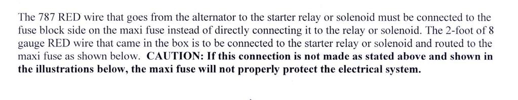
7 STEP 6 Wiring the engine and starter A. The starter solenoid group of wires. 1. The #719 Lt.Blu wire marked start attaches to the S terminal of the starter solenoid on Ford and GM style solenoids ( refer to illustrations H & G respectively ) and the ST terminal on Mopar style relays. This wire comes from the start terminal of the ignition switch and through the neutral safety switch on all systems except Mopar. 2. The #781 brown wire marked I term attaches to the I terminal of the Ford and GM style start solenoids and may be used with the Mopar start relay when a diode is included in the circuit (refer to illustration D.This wire is used as a resistor bypass only when a Ballast Resistor is installed. 3. The large #716 and #787 red wires attach to the battery cable post of the starter solenoid. NOTE: The kit includes a MAXIFUSE tto protect the entire electrical system.before attaching the large #716 and #787 red wires to the solenoid, mount the maxifuse in a convenient location near the solenoid. Cut the red wires to the correct length and attach to one side of the maxifuse with a terminal provided in the kit. Attach the other side of the maxifuse to the solenoid battery cable post with some of the remaining heavy red wire and terminals provided. This must be used for the overall system protection. 4. The #783 black wire attaches to the G terminal on the Mopar style relay. This wire is not used on Ford or GM style solenoids.. B. The ignition module group of wires Motorcraft (Refer to illustration E ) 1. The #720 red/white wire attaches to the red wire in the 2 way connector of the module. 2. The #719lt.blu wire attaches to the white wire in the 2-way connector of the module. 3. The #782 green wire attaches to the green wire in the 4-way connector of the module. Prestolite (Refer to illustration F ) 1. The #782 green wire attaches to the green wire of the control unit. 2. The #720 red/white attaches to the yellow wire of the control unit. HEI and point style ignition systems (Refer to illustration G ) 1. The #782 green, #719 lt.blu and #720 red/white wires are not used going to the ignition module.wires may be cut off or taped and stored. NOTE: On HEI ignition systems, the ballast resister is not used and the red/white wire referred to on line 5` of step 5 is the only wire used. 5
8 C. The alternator and accessory wires 1. The wires marked alt attach as follows; The large #715 and #787 red wires attach to the output post of the alternator and the brown #714 wire attaches to the I terminal of the regulator on Motorcraft systems ( refer to illustration I ), to the #1 terminal on internally regulated GM alternators ( refer to illustration J, to the #3&4 terminals of the GM externally regulated alternator regulator ( refer to illustration K ), to the ign and field terminals on Mopar regulators and alternators ( refer to illustration M ) and to the regulator plug on Motorola systems ( refer to illustration L ). 2. The purple #722 wire marked oil sender attaches to the oil pressure sending unit. 3. The purple/white #721 wire marked temp sender attaches to the engine temperature sending unit. 4. The gray/white #701 wire marked engine fan relay activates the electric fan relay if the vehicle is so equipped. 5. The brown #702 wire marked a/c comp powers the air conditioning compressor. STEP 7 Routing and attaching the front lighting harness 1. Feed the headlight harness through the hole in the radiator support. It may be necessary to remove the T connectors on the loom covering to get the wires through the hole and then reinstall them once the wiring is routed. Removing the headlight assemblies will aid in the installation. 2. Run the left marker lamp EE through the fender and plug in the light. 3. Plug in the left turn signal/park lamp DD. 4. Plug in the left headlight CC. 5. Run right light harness assembly under grill shell and attach with clips located behind grill. 6. Run the right marker lamp HH harness through the fender and plug in the light. 7. Plug in the right turn signal/park light GG. 8. Plug in the right headlight FF. STEP 8 Routing and installing the tail light harness 1. Starting from the rear, feed the wires for plug U through the hole in the left rear inner fender well and pull forward until the harness will reach the main harness connector B behind the emergency brake. The plug U is in with the parts in the bag kit and should be installed onto the wires after they have been routed through the fender well. Plug together plug U and B. 2. Install the grommet into the hole around the harness after the harness has been positioned along the floor pan. 3. Route the harness in the channel along the base of the wheel well. 4. Plug in the left rear marker light Y if so equipped. 5. Attach the pink wire marked fuel sender to the fuel tank sending unit with a terminal provided. 6. Terminate black ground wire marked ground to a suitable ground. 7. Plug in the left rear tail light connector X or install the new connector Z that is supplied. Black is ground, white is taillights, white/black is back-up lights and green/black is left turn. 8. Route the right side harness across under the body and secure with the factory clips or wire ties. 9. Plug in the right side marker W if so equipped. 10. Plug in the right rear taillight connector V or install the new connector AA that is supplied. Black is ground, white is taillights, white/black is back-up lights and green is right turn. 6
9 STEP 9 Testing the system 1. Attach a small battery charger, 10 amp or less, to the positive and negative battery cables. Cables should still not be attached to the battery. 2. Turn on the charger and check each system for proper operation. 3. If all systems are operating properly, then attach the battery cables to the battery. 4. Congratulations on your installation! 7
10 Color Ga. No. Connect to Origin Section of Origin ACCESSORY SECTION Gry/Wht Cooling Fan Switch Electric Fan Headlight Section A Brn AC/Heat Switch A/C Compressor Engine Section A Red Cigarette Lighter B+ Fuse Panel Fuse Panel Red AC/Heat Switch B+ Fuse Panel Fuse Panel Red/Wht Wiper Switch B+ Fuse Panel Fuse Panel Gry/Wht Cooling Fan Switch B+ Fuse Panel Fuse Panel Wht/Red Clock Fuse Panel Fuse Panel ALTERNATOR SECTION Brn Alternator Exciter Fuse Panel Fuse Panel Red Alternator B+ Fuse Panel Fuse Panel Red Alternator B+ Starter relay (B) Engine Section DIMMER SWITCH SECTION Red/Wht Dimmer Switch Headlight Switch Headlight Section B Gry/Red Dimmer Switch High Beam Headlight Section A Gry Dimmer Switch Low Beam Headlight Section A STARTER SOLENIOD SECTION Lt.Blu Start Solenoid (S) Term Ign. Switch Start Ign. Switch Section Brn Start Solenoid (I) Term Coil (+) Engine Section A Blk Starter Relay (G) Ground Backup Switch Backup Section Red Battery Starter Solenoid B+ Fuse Panel Fuse Panel Red Starter Relay (B) Alternator B+ Alternator Section EMERGENCY BRAKE SECTION Blk Emergency Brake Switch Brake Warn Indicator Instr. Panel Section Light Blk Brake Pressure Switch (master cylinder) Emergency Brake Indicator Instrument Panel Section BRAKE SWITCH SECTION Rd/Bk Brake Switch B+ Fuse Panel Fuse Panel Pnk Brake Switch Turn Signal Switch Turn Signal Section ENGINE SECTION A Red/Wht Coil B+ Fuse Panel Fuse Panel Ppl/Wht Temperature Sending Unit Temp. Gauge Inst. Panel Section Ppl Oil Pressure Sending Unit Oil Pressure Gauge Inst. Panel Section Ppl Tachometer Source Tachometer Inst. Panel Section Brn A/C Compressor Fuse Panel Accy. Section Switches Red Electric Choke Fuse Panel Fuse Panel Grn Coil (-) Ign. Module Engine Section A Brn Coil (+) Ballast Bypass Starter Relay Engine Section A Tan Heater Motor Heater Switch Heater Section Ylw Washer Motor Wiper Switch Accessory Switch Table 1.1 Wire Connection Index (1 of 3) 8
11 Color Ga. No. Connect to Origin Section of Origin BACKUP SECTION Blk Backup Switch Starter Relay Starter Solenoid Sect. Red Backup Switch Fuse Panel Fuse Panel Wht/Blk Backup Switch Backup Lights Tail Section Org Transfer Case 4WD Indicator Instr. Panel Section HEADLIGHT SECTION A Rd/Bk Horn B+ Horn Relay Fuse Panel Grn Right Front Turn Signal Turn Signal Switch Turn Signal Section Grn/Blk Left Front Turn Signal Turn Signal Switch Turn Signal Section Wht Park Lights Headlight Switch Headlight Section B Gry/Red High Beam Dimmer Switch Dimmer Sw. Section Gry Low Beam Dimmer Switch Dimmer Sw. Section Gry/Wht Cooling Fan Fan Switch Accy. Section B+ HEADLIGHT SECTION B Red Headlight Switch B+ Fuse Panel Fuse Panel Red/Wht Headlight Switch Dimmer Switch Dimmer Sw. Section Wht Headlight Switch Tail Lights Tail Section Wht Headlight Switch Park Lights Headlight Section A Orn Headlight Switch Instr. Panel Lighting Instr. Panel Section IGNITION SWITCH SECTION Red/Wht Ign. Switch (Coil Ign.) Fuse Panel Fuse Panel Ylw Ignition Switch (Hot) Fuse Panel Fuse Panel Red Ignition Switch B+ Fuse Panel Fuse Panel Lt. Blu Ignition Switch Start Starter Solenoid Engine Section A Brn Ignition Switch (Accessory) Fuse Panel Fuse Panel Blk Ignition Switch (Ground) Fuse Panel Fuse Panel INSTRUMENT PANEL SECTION Ylw Voltmeter Source and Fuse Panel Fuse Panel Gauges B+ Gy/Bk High Beam Indicator Dimmer Switch Dimmer Sw. Section Gn/Bk Left Turn Indicator L Front Turn Signal Turn Signal Section Grn Right Turn Indicator R Front Turn Signal Turn Signal Section Org Instr. Panel Lighting Headlight Switch Headlight Section B Pnk Fuel Gauge Fuel Sending Unit Tail Section Ppl/Wht Temperature Gauge Temp. Sending Unit Engine Section A Ppl Oil Pressure Gauge Oil Pres. Sending Unit Engine Section A Ppl Tachometer Tachometer Source Engine Section A Blk Emergency Brake Indicator Emer. Brake Switch Engine Section Red Emer. Brake Indicator B+ Fuse Panel Fuse Panel Org WD Indicator 4WD Switch Engine Section A Table 1.1 Wire Connection Index (2 of 3) 9
12 Color Ga. No. Connect to Origin Section of Origin TURN SIGNAL SECTION Pnk Emer. Flasher Switch B+ Emer. Flasher Relay Fuse Panel Red/Wht Turn Signal Sw.Flasher B+ Turn Flasher Relay Fuse Panel Blk/Wht Horn Switch Horn Relay Fuse Panel Lt.Grn Turn Signal Switch R Rear Turn Signal Tail Section Lt.Gn/Blk Turn Signal Switch L Rear Turn Signal Tail Section Grn Turn Signal Switch R Front Turn Signal Headlight Section A Pnk Turn Signal Switch Brake Switch Engine Section A Grn/Blk Turn Signal Switch L Front Turn Signal Headlight Section A RADIO SECTION Blu Radio B+ Switched Fuse Panel Fuse Panel TAIL SECTION Blk Grounding Point Tail lights Tail Section Lt.Grn R Rear Turn Signal Turn Signal Switch Turn Signal Section Lt.Gn/Bk L Rear Turn Signal Turn Signal Switch Turn Signal Section Pnk Fuel Sending Unit Fuel Gauge Instr. Panel Section Wht Tail Lights Headlight Switch Headlight Section B Wht/Blk Backup Lights Backup Switch Cruise Control Section HEATER SECTION Red Heater Switch B+ Fuse Panel Fuse Panel Brn Heater Switch Heater Resistor Heater section Brn/Wht Heater Switch Heater Resistor Heater section Tan Heater Switch Heater Resistor Heater section Tan Heater Switch Heater Motor Engine Section A HEATER RESISTOR SECTION Brn Heater Resistor Heater Switch Heater Section Brn/Wht Heater Resistor Heater Switch Heater Section Tan Heater Resistor Heater Switch Heater Section IGNITION MODULE SECTION Grn Coil Signal Coil (-) Engine Section A Red/Wht Ignition Power Coil (+) Engine Section A LtBlu Crank Signal Starter Solenoid (S) Terminal Starter Solenoid Section Table 1.1 Wire Connection Index (3 of 3) 10
13 11
14 12
15 13 (This connector is in the bag kit and is installed by the customer.)
16 Illustration D Mopar Ignition (Start/Run) System Illustration E Duraspark Electronic Ignition (Start/Run) System 14
17 Illustration F Prestolite BID Ignition (Start/Run) System Illustration G Delco Ignition (Start/Run) System 15
18 Illustration H Ford Ignition (Start/Run) System Illustration I Motorcraft Alternator 16
19 Illustration J Delco Alternator (Internal) Illustration K Delco Alternator (External) 17
20 Illustration L Motorola Charging System Illustration M Mopar Alternator 18
21 19 19
22 20 20
23 Diagram 2 Electric Fan Relay (Relay Kit Painless Part #30101) 21

24 22
25 Perfect Performance Products, LLC shall in no event be liable in contract or tort (including negligence) for special, indirect, incidental, or consequential damages, such as but not limited to, loss of property damage, or any other damages, costs or expenses which might be claimed as the result of the use or failure of the goods sold hereby, except only the cost of repair or replacement. P/N Painless Wiring Manual April 2005 Copyright 1996 by Perfect Performance Products, LLC Painless Performance Limited Warranty and Return Policy Chassis harnesses, fuel injection harnesses, and Striker ColdShot units are covered under a lifetime warranty. All other products manufactured and/or sold by Painless Performance are warranted to the original purchaser to be free from defects in material and workmanship under normal use. Painless Performance will repair or replace defective products without charge during the first 12 months from the purchase date. No products will be considered for warranty without a copy of the purchase receipt showing the sellers name, address and date of purchase. You must return the product to the dealer you purchased it from to initiate warranty procedures. 23
20 CIRCUIT ATO FUSE CENTER INSTALLATION INSTRUCTIONS
 2501 Ludelle Street Fort Worth, Texas 76105 817-244-6212 phone 817-244-4024 fax 800-423-9696 Tech E-Mail: painless@painlessperformance.com Web: www.painlessperformance.com 30003 20 CIRCUIT ATO FUSE CENTER
WIRE HARNESS INSTALLATION INSTRUCTIONS
 WIRE HARNESS INSTALLATION INSTRUCTIONS For Installing: #10206 Classic Plus Customizable GM Pickup Chassis Harness 1967-72 28 Circuit Manual #90510 PERFECT PERFORMANCE PRODUCTS, LLC Painless Performance
INSTRUCTIONS. 20 Circuit Wiring Kit Instructions October 2009, Speedway Motors, Inc.
 1 MAIN FUSE PANEL The main fuse panel harness s designed to be mounted under the dash a the firewall in an area close to the steering column. The enclosed representation of the main dash harness shows
jegs.com
 Contents Wiring Harness w/ Fuse Panel Installation Instructions Turn Signal Plug w/ Terminals 2 Headlight Plugs 3/4 Grommet 10 ¼ Terminals 4 Ring Terminals 10 Wire Ties Fusible Link 2 Screws & Nuts 2 Plastic
Modular Wire Harness Installation Instructions
 Modular Wire Harness Installation Instructions 10301 MODULAR 4-CIRCUIT CHASSIS HARNESS Manual #90529 Painless Performance Products Division Perfect Performance Products, LLC 2501 Ludelle Street, Fort Worth,
WIRE HARNESS INSTALLATION INSTRUCTIONS
 WIRE HARNESS INSTALLATION INSTRUCTIONS For Installing: #10205 Classic Plus Customizable GM Pickup Chassis Harness 1973-87 27 Circuit Manual #90507 Painless Performance Products, LLC 2501 Ludelle Street
Wire Harness Installation Instructions For Installing:
 Wire Harness Installation Instructions For Installing: #20106 Classic Plus Customizable Tri-Five Chevy Harness 28 Circuit #20107 Classic Customizable Tri-Five Chevy Harness 21 Circuit Manual #90553 Painless
Wire Harness Installation Instructions
 Wire Harness Installation Instructions For Installing: Part #10143 Landcruiser / Scout Weatherproof Harness Manual #90548 Painless Performance Products Division Perfect Performance Products, LLC 2501 Ludelle
Wire Harness Installation Instructions
 Wire Harness Installation Instructions For Installing: #10127 Customizable Mopar Chassis Harness 21 Circuit Manual #90542 Painless Performance Products, LLC 2501 Ludelle Street Fort Worth, TX 76105-1036
-----
 ----- - - -- - - -- - -- - - NOTE: #32 WIRE DOES NOT APPLY TO 8 AND 14 CIRCUIT HARNESSES ELECTRIC FAN #1 TO FAN SWITCH (GRAY) #21 TEMP. GAUGE (GREEN) #2 TO AC SWITCH (BLACK) JUMPER WIRE ALTERNATORS
Wire Harness Installation Instructions For Installing: #20102 Classic Plus Customizable GM Muscle Car Chassis Harness 25 Circuit
 Wire Harness Installation Instructions For Installing: #20102 Classic Plus Customizable 1969-74 GM Muscle Car Chassis Harness 25 Circuit Manual #90552 Painless Performance Products Division Perfect Performance
Wire Harness Installation Instructions
 Wire Harness Installation Instructions FOR INSTALLING: PART #10108 20 CIRCUIT BRONCO HARNESS Manual #90521 Painless Performance Products Division Perfect Performance Products, LLC 2501 Ludelle Street,
Wire Harness Installation Instructions
 Wire Harness Installation Instructions For Installing: #20101 Classic Plus Customizable 67-68 Camaro/Firebird Harness - 24 Circuit Manual #90551 Painless Performance Products Division Perfect Performance
Off-Road Switch Panel Installation Instructions
 Off-Road Switch Panel Installation Instructions 50330: Off-road 4 Toggle switches/dash Mount w/keyed Ignition Switch 50332: Off-road 6 Toggle switches/dash Mount w/keyed Ignition Switch Painless Performance
Wire Harness Installation Instructions
 Wire Harness Installation Instructions For Installing: Part #10107 Wiring Harness (Land Cruiser, Scout/12 circuit) Manual #90535 Painless Performance Products Division Perfect Performance Products, LLC
WIRE HARNESS INSTALLATION INSTRUCTIONS
 WIRE HARNESS INSTALLATION INSTRUCTIONS For Installing: 22 Circuit Chassis Harness Kits #10105 Classic Customizable Jeep CJ ( 74-back) #10106 Classic Customizable Jeep CJ (75-later) Manual #90504 Painless
Instrument Cluster 30 33B 39B A B C D E F E F G H J. Connector. Circuit Branch #4. Circuit Branch #5. Circuit. Branch #6 150A. Ground.
 16 4D, 43 4B 4A & 130 100 50 39A,B,C 300 4C 4B 4C 107 3C 3D 3C 3G 3B 3F 3A 16A 3G 116 104 93 3B 3D 2E 16A 2C 2D 2B 2A 44 40 27A 40B 115 27 40A,C,E 8A,B,C Mating is plugged into accessory connector Power
Wire Harness Installation Instructions
 Wire Harness Installation Instructions For Installing: Part #50001 Race Car Kit/8 Circuit Part #50201 8 Switch Dash Mounted Panel Part #50202 8 Switch Roll Bar Mounted Panel Manual #90502 Painless Performance
Wire Harness Installation Instructions
 Wire Harness Installation Instructions For Installing: #10123 Customizable Ford Color Coded Harness 21 Circuit Manual #90545 Painless Performance Products, LLC 2501 Ludelle Street Fort Worth, TX 76105-1036
Wire Harness Installation Instructions
 Wire Harness Installation Instructions FOR INSTALLING: PART #10130 14 CIRCUIT MICRO FUSE BLOCK REMOTE MOUNT HARNESS Manual #90525 Painless Performance Products Division Perfect Performance Products, LLC
40A A 40B. Horn Relay Connector. Brake Switch. Third Brake Light. Brake Switch. Brake Switch. Wires. page 3. Rear Body Feed Wires.
 Fuse Box Connections (viewed from underside) 4D 4C 4D 0 50 300 4C 43 7 39 3 6 4 93 A 2G 2F 2E 2D 2C 2B 2G 2F 2E 40 69A 2 1 5 27 69A 3A B 40A,B 11A,B 40A 156 Dimmer Dome Feed page 2 Horn Relay 2D 2 29 40B
INSTRUCTIONS Circuit Wiring Kit Instructions _2017. Fuse Box Connections. (viewed from underside) 2018, Speedway Motors, Inc.
 2018, Speedway Motors, Inc.") Fuse Box Connections (viewed from underside) 4D 4C 100 50 300 4D 4C 4B 4A 43 107 39 103 3B 2G 104 93 2F 2E 2D 2C 2B 40 69A 102 101 105 2G 2F 2E 3A A 2A B 40A,B 27 69A 106 201, Speedway Motors, Inc. 1 Fuse
Fuse Box Connections (viewed from underside) 4D 4C 100 50 300 4D 4C 4B 4A 43 107 39 103 3B 2G 104 93 2F 2E 2D 2C 2B 40 69A 102 101 105 2G 2F 2E 3A A 2A B 40A,B 27 69A 106 201, Speedway Motors, Inc. 1 Fuse
Wire Harness Installation Instructions
 Wire Harness Installation Instructions For Installing: Part #20122 14 Circuit 1969 1970 Ford Mustang Manual #90557 Perfect Performance Products, LLC Painless Performance Products Division 2501 Ludelle
Wire Harness Installation Instructions
 Wire Harness Installation Instructions For Installing: #10112 Classic Customizable Chevy P/U Harness 19 Circuit Manual #90519 Perfect Performance Products, LLC Painless Performance Products Division 2501
Wire Harness Installation Instructions For Installing:
 Wire Harness Installation Instructions For Installing: #10117 Direct Fit 1967-77 F-Series Ford Truck Harness w/o es 21 Circuit or #10118 Direct Fit 1967-77 F-Series Ford Truck Harness w/ es 21 Circuit
Wire Harness Installation Instructions For Installing:
 Wire Harness Installation Instructions For Installing: #10120 Classic Customizable Trunk Mount Harness 21 Circuit #10220 Classic Plus Customizable Trunk Mount Harness 28 Circuit Painless Performance Products,
Installation Instructions For 50330, 50331, 50332, and Off Road Switch Panels
 Installation Instructions For 50330, 50331, 50332, and 50333 Off Road Switch Panels 2501 Ludelle Street Fort Worth, Texas 76105 817-244-6212 Phone 817-244-4024 Fax 888-350-6588 Sales 800-423-9696 Tech
INSTRUCTIONS 12 Circuit Wiring Kit Instructions
 Fan 47 9 56 4 7 6 72 40 45 48 5 8 6 Gauge Power Temp Sender Headlight Power Power Radio Constant Power Instruments and Dash Rear of Vehicle Ignition and Lights Fuse Panel & Front of Vehicle Horn Alt Excitor
Wire Harness Installation Instructions
 Wire Harness Installation Instructions For Installing: #10101 Classic Customizable Harness-GM Keyed Column-21 Circuit #10102 Classic Customizable Harness-Non GM Keyed Column-21 Circuit #10103 Classic Customizable
Wire Harness Installation Instructions
 Wire Harness Installation Instructions FOR INSTALLING: #10308 Basic Customizable Chassis Harness 18 Circuit Manual #90527 Painless Performance Products, LLC 2501 Ludelle Street Fort Worth, TX 76105-1036
Wire Harness Installation Instructions
 Wire Harness Installation Instructions For Installing: #20121 Direct Fit Mustang Chassis Harness 1967-1968 22 Circuit Manual #90556 Perfect Performance Products, LLC Painless Performance Products Division
accessory connection rear body connection 40G 17A instrument cluster and map lamp ground 150A,B 15A 14A Circuit Branch 500A fog lamp switch
 accessory rear body 19 9 11 instrument cluster and map 10A, 0 4 3 7 40G 18 30 17A 24 1A 14A 9 8A instrument cluster 4E 31 3 121 11 33 401 10A 39A 400 30 washer and wiper switch 93A, 94 93 glovebox, map
Mustang Classic Update Series Kit
 accessory rear body 19 9 11 instrument cluster and map 10A, 0 4 3 7 40G 18 30 17A 24 1A 14A 9C 8A instrument cluster 4E 31 3 121 11 401 10A 3 400 30 washer and wiper switch 93A, 93 glovebox, map light,
Wire Harness Installation Instructions
 Wire Harness Installation Instructions For Installing: #10140 Customizable Weatherproof Chassis Harness 26 Circuit Manual #90531 Painless Performance Products, LLC 2501 Ludelle Street Fort Worth, TX 76105-1036
WIRE SYSTEM PRO15 ULTRA SMALL 15 FUSE 24 CIRCUIT 118 TERMINAL PANEL WIRE SYSTEM
 TECH UPPORT: 503.693.1918 WIRE YTEM WWW.KEEPITCLEANWIRING.COM PRO15 ULTRA MALL 15 FUE 24 CIRCUIT 118 TERMINAL PANEL WIRE YTEM IMPORTANT: The below instructions are referring to a general installation.
Wire Harness Installation Instructions
 Wire Harness Installation Instructions For Installing: Part #20120 14 Circuit Ford Mustang (1965-1966) Manual #90526 Perfect Performance Products, LLC Painless Performance Products Division 2501 Ludelle
Rear Body 40D 156A 24 17A 151 3D. 8A,8B,8C under hood light. Horn Relay 91
 fuse box as viewed from the wire entry side Mating connector is plugged into Power Accessory connector 40D Rear Body 19 18 9B 30 LH Courtesy Light 40A,D 4D, 43 156B,C 16 16A 4C 3D 3C 16A 3G 4B 3G 116 4A&130
UNIVERSAL WIRING HARNESS Installation Manual
 UNIVERSAL WIRING HARNESS Installation Manual Terminals are provided for most connections on your wiring kit. Following the gauge manufacturer s instructions, use the terminals supplied with your gauge
Wire Harness Installation Instructions
 Wire Harness Installation Instructions For Installing: Part #20120 22 Ford Mustang (1965-1966) Manual #90526 Perfect Performance Products, LLC Painless Performance Products Division 2501 Ludelle Street
200-4R TRANSMISSION LOCK-UP HARNESS INSTALLATION INSTRUCTIONS
 2501 Ludelle Street Fort Worth, Texas 76105 817-244-6212 Phone 817-244-4024 Fax 888-350-6588 Sales 800-423-9696 Tech E-mail: painless@painlessperformance.com Web: www.painlessperformance.com 60110 200-4R
Classic Update Series
 Classic Update Series 0-4 Ford Falcon and 0- Mercury Comet end view of terminal START HERE! PLEASE READ THIS EFORE STARTING INSTALLATION! This wiring kit is designed for ease of installation. Please read
Trail Rocker Installation Instructions
 Trail Rocker Installation Instructions Manual #90580 For Installing Painless Part Numbers: 57000 and 57001 Painless Performance Products recommends you, the installer, read this installation manual from
Trail Rocker Installation Instructions
 Trail Rocker Installation Instructions Manual #90581 For Installing Painless Part Numbers: 57002 Painless Performance Products recommends you, the installer, read this installation manual from front to
Classic Update Series
 Classic Update Series 1964-1966 Ford Mustang START HERE! PLEASE READ THIS EFORE STARTING INSTALLATION! This wiring kit is designed for ease of installation. Please read the guidelines below, EFORE STARTING
Classic Update Series
 Classic Update Series START HERE! PLEASE READ THIS EFORE STARTING INSTALLATION! This wiring kit is designed for ease of installation. Please read the guidelines below, EFORE STARTING your installation
30107 & PACK & 6-PACK RELAY BANK
 30107 & 30108 2501 Ludelle Street Fort Worth, Texas 76105 817-244-6212 Phone 817-244-4024 Fax 888-350-6588 Sales 800-423-9696 Tech E-mail: painless@painlessperformance.com Web: www.painlessperformance.com
Classic Update Series
 Classic Update Series 73-79 Ford F100-350 & 78-9 Ford ronco START HERE! PLEASE READ THIS EFORE STARTING INSTALLATION! This wiring kit is designed for ease of installation. Please read the guidelines below,
Headlight Switch Connector. Brake Switch. Lead Wires. Main Power Feed from Starter. Fuse Box Connections (viewed from underside)
") www.americanautowire.com 86-933-0801 TH KT DOE NOT UPPORT TOCK (ORGNAL) GENERATOR. THE DEGN OF THE KT DEGNED TO UPPLY MORE POWER THAN THE GENERATOR ALE TO UPPLY. 16 68A 4D 4C 4D 0 0 0 4C 4 43 7 39 3 Dimmer
www.americanautowire.com 86-933-0801 TH KT DOE NOT UPPORT TOCK (ORGNAL) GENERATOR. THE DEGN OF THE KT DEGNED TO UPPLY MORE POWER THAN THE GENERATOR ALE TO UPPLY. 16 68A 4D 4C 4D 0 0 0 4C 4 43 7 39 3 Dimmer
headlights [H only] dip switch hi beam flasher pillar interior lights rear interior panel switch C/D cubby A B boot map light LED strip
![headlights [H only] dip switch hi beam flasher pillar interior lights rear interior panel switch C/D cubby A B boot map light LED strip](/thumbs/74/70768506.jpg "headlights [H only] dip switch hi beam flasher pillar interior lights rear interior panel switch C/D cubby A B boot map light LED strip") to Alpine unit exterior lights [S or H or F] FUSE BOX LIGHTS ENGINE ACC reverse light, brake Note: diode (6a 50v) prevents triggering of Alpine backup camera when brake light is closed brake L tail plate
to Alpine unit exterior lights [S or H or F] FUSE BOX LIGHTS ENGINE ACC reverse light, brake Note: diode (6a 50v) prevents triggering of Alpine backup camera when brake light is closed brake L tail plate
Classic Update Series
 Classic Update Series 67-72 Ford Truck START HERE! PLEASE READ THIS EFORE STARTING INSTALLATION! This wiring kit is designed for ease of installation. Please read the guidelines below, EFORE STARTING your
Classic Update Series
 Classic Update Series 62-65 Ford Fairlane and 62-63 Mercury Meteor end view of terminal START HERE! PLEASE READ THIS EFORE STARTING INSTALLATION! This wiring kit is designed for ease of installation. Please
CLASSIC UPDATE WIRING KIT
 by Randy Irwin 1955-57 CLASSIC UPDATE WIRING KIT Randy Irwin - Technical Writer Randy has been involved in the Chevy parts business for over 25 years. He is a wizard at creating, making and modifying custom
Opel Manta/Ascona/1900 Wiring Diagram (Based on using Universal EZ20 wiring harness)
") Opel Manta/Ascona/1900 Wiring Diagram (Based on using Universal EZ20 wiring harness) Index: 1 - Notes, egend, & Shipping Check ist i thru v - Instructions, Dos and Don'ts 2 - Fuse Box Diagram 3 - Front
Opel Manta/Ascona/1900 Wiring Diagram (Based on using Universal EZ20 wiring harness) Index: 1 - Notes, egend, & Shipping Check ist i thru v - Instructions, Dos and Don'ts 2 - Fuse Box Diagram 3 - Front
INSTALLATION INSTRUCTIONS
 Accessory Application Publications No. INSTALLATION INSTRUCTIONS S (DX, HX, VP) 2005 CIVIC 2- AND 4- DOOR AII 27865-30866 Issue Date SEP 2005 NOTE: Fog Lights cannot be installed if the vehicle is equipped
Installation Instructions For 50340
 Installation Instructions For 50340 2501 Ludelle Street Fort Worth, Texas 76105 817-244-6212 Phone 817-244-4024 Fax 888-350-6588 Sales 800-423-9696 Tech E-mail: painless@painlessperformance.com Web: www.painlessperformance.com
Trail Rocker Installation Instructions
 Trail Rocker Installation Instructions Trail Rocker - Genesis Bracket For Installing Painless Part Number: 57200 Manual # 90591 To be used with Painless Kit # s: 57000-57005 Painless Performance Products
Headlight Switch Connector. Brake Switch. Lead Wires. Main Power Feed from Starter. Fuse Box Connections (viewed from underside)
") 0 Heller Pl #17 W ellmawr, NJ 0031 6-933-001 TH KT DOE NOT UPPORT TOCK (ORGNL) GENERTOR. THE DEGN OF THE KT DEGNED TO UPPLY MORE POWER THN THE GENERTOR LE TO UPPLY. 16 6 4D 4C 4D 0 0 0 4C 4 4 43 7 39 3
0 Heller Pl #17 W ellmawr, NJ 0031 6-933-001 TH KT DOE NOT UPPORT TOCK (ORGNL) GENERTOR. THE DEGN OF THE KT DEGNED TO UPPLY MORE POWER THN THE GENERTOR LE TO UPPLY. 16 6 4D 4C 4D 0 0 0 4C 4 4 43 7 39 3
Trail Rocker Installation
 Trail Rocker Installation Instructions Customizable Trail Rocker Control System For Installing Painless Part Number: 57100 Manual #90616 Painless Performance Products recommends you, the installer, read
ISIS Power Manual and Installation Guide Race Car Replicas- Superlite Coupe
 ISIS Power Manual and Installation Guide Race Car Replicas- Superlite Coupe Table of Contents Overview... 2 System Details... 3 Kit Includes... 3 Technical Specifications... 3 Harness Descriptions... 4
DASH/MAIN HARNESS. NOTE: wires 400 & 401, must be twisted together.
 Electric Speedo Ground 151 Turn Flasher 16A 4 150 8A, Cluster Connections 31 33 30 35 151 (electric speedo) 402 401 NOTE: wires 400 & 401, must be twisted together. 156D, E Panel Dimmer 8A 9, C 2D Headlight
INSTALLATION INSTRUCTIONS
 INSTALLATION INSTRUCTIONS Accessory Application Publications No. CIVIC AII 24171 S 2- AND 4-DOOR Issue Date (DX, HX) AUG 2002 NOTE: Fog Lights cannot be installed if the vehicle is equipped with an optional
Headlight Switch Connector. Brake Switch. Lead Wires. Main Power Feed from Starter
 40 3C 40, 2E 2C 2 2F Dimmer witch 12 11 & 11 2C 2 Horn Relay Dome Courtesy feed 40 16 Main Power Feed from tarter 2 12 V attery rake witch rake witch 40 17 17 rake witch Third rake Light Headlight witch
INSTALLATION INSTRUCTIONS
 INSTALLATION INSTRUCTIONS Accessory Application Publications No. S CIVIC 2 AND 4-DOOR (EX, LX) AII 24188 Issue Date AUG 2002 NOTE: Fog Lights cannot be installed if the vehicle is equipped with an optional
INSTALLATION INSTRUCTIONS
 INSTALLATION INSTRUCTIONS Accessory Application Publications No. S P/N 08V31-SCV-100B 2008 ELEMENT (SC) AII 36532 Issue Date MAY 2007 PARTS LIST Relay bracket Right fog light Relay Left fog light Fuse
INSTALLATION INSTRUCTIONS
 INSTALLATION INSTRUCTIONS Accessory Application Publications No. All 26124 CR-V Issue Date SEP 2003 P/N 08V31-S9A-112 PARTS LIST 4 Washer-bolts, 6 x 20 mm Left fog light 2 Small spring nuts Right fog light
INSTALLATION INSTRUCTIONS
 INSTALLATION INSTRUCTIONS Accessory Application Publications No. All 27176-28932 2005 CR-V Issue Date S P/N 08V31-S9A-115 FEB 2005 PARTS LIST 6 Washer-bolts Left fog light 6 Spring nuts Harness bracket
Perfect Performance Products, LLC Painless Performance Products Division 2501 Ludelle St. Fort Worth, Texas (800)
") PERFECT HI-VELOCITY 68MM THROTTLE BODY Installation Instructions Part # 65301 1991-1998 Jeep 4.0L Engines w/perfect Engine Management System P/N 65140, 65141 OR All Jeep 4.0L Engines in Cherokee, Grand
PERFECT HI-VELOCITY 68MM THROTTLE BODY Installation Instructions Part # 65301 1991-1998 Jeep 4.0L Engines w/perfect Engine Management System P/N 65140, 65141 OR All Jeep 4.0L Engines in Cherokee, Grand
P/N & GM LS1 FUEL INJECTION WIRE HARNESS INSTALLATION INSTRUCTIONS
 P/N 605 & 6053 00-04 GM LS1 FUEL INJECTION WIRE HARNESS INSTALLATION INSTRUCTIONS Manual P/N 90544 nd Edition July 014 PAINLESS PERFORMANCE PRODUCTS 501 Ludelle Street - Fort Worth, Texas 76105-1036 -
Classic Update Series
 START HERE! PLEASE READ THIS BEFORE STARTING INSTALLATION! This wiring kit is designed for ease of installation. Please read the guidelines below, BEFORE STARTING your installation to guarantee a successful
INSTALLATION INSTRUCTIONS
 Accessory Application Publications No. INSTALLATION INSTRUCTIONS S (LX, EX) CIVIC 2- AND 4- DOOR AII 25449 Issue Date SEP 2003 NOTE: Fog Lights cannot be installed if the vehicle is equipped with an optional
INSTALLATION INSTRUCTIONS
 INSTALLATION INSTRUCTIONS Accessory Application Publications No. All 27176 2005 CR-V Issue Date P/N 08V31-S9A-114 SEP 2004 PARTS LIST 25 Wire ties Left fog light 6 Washer-bolts Right fog light 6 Spring
Track Rocker Installation Instructions
 Track Rocker Installation Instructions For Installing Painless Part Numbers: 58103: 8-Switch Customizable Track Rocker Switch Panel w/ Flanged Mount 58106: 6-Switch Customizable Track Rocker Switch Panel
1962 Wiring Diagram. The Basics Part One. by Bob Mannel
 The Basics Part One 1962 Wiring Diagram by Bob Mannel Most restorers fear the wiring probably since it seems to be the most abused system in our Fairlanes. With cuts, splices, and extra wires running hither
TOYOTA YARIS HATCHBACK TVIP V3 (RS3200) Preparation
 Preparation") Preparation Part Number: 08586-53810 Kit Contents Item # Quantity Reqd. Description 1 1 V3 ECU 2 1 Piezo Buzzer 3 1 Wire Harness 4 1 ECU Mounting Bracket 5 2 Remote Control Transmitter 6 1 Butyl Tape 7
Preparation Part Number: 08586-53810 Kit Contents Item # Quantity Reqd. Description 1 1 V3 ECU 2 1 Piezo Buzzer 3 1 Wire Harness 4 1 ECU Mounting Bracket 5 2 Remote Control Transmitter 6 1 Butyl Tape 7
Installation Instructions. Part #65100
 Installation Instructions Part #65100 Perfect Performance Products, LLC Painless Performance Products Division 2501 Ludelle Street Fort Worth, TX 76105-1036 800-423-9696 phone 817-244-4024 fax Web Site:
PERFECT HI-VELOCITY 62MM THROTTLE BODY
 PERFECT HI-VELOCITY 62MM THROTTLE BODY Installation Instructions Part # 65300 1991-1998 Jeep 4.0L Engines OR All Jeep 4.0L Engines in Cherokee, Grand Cherokee and Wrangler 1991-2005 w/4 wire IAC ONLY.
POWER SOURCE (Current Flow Chart)
") The chart below shows the route by which current flows from the battery to each electrical source (Fusible Link, Circuit Breaker, Fuse, etc.) and other parts. The next page and following pages show the
The chart below shows the route by which current flows from the battery to each electrical source (Fusible Link, Circuit Breaker, Fuse, etc.) and other parts. The next page and following pages show the
INSTALLATION INSTRUCTIONS
 INSTALLATION INSTRUCTIONS Accessory Application Publications No. AII 24288 S ELEMENT Issue Date DEC 2002 PARTS LIST Fog Light Kit ( P/N 08V31-SCV-100 2 Fog lights Switch harness TOOL AND SUPPLIES REQUIRED
INSTALLATION INSTRUCTIONS
 INSTALLATION INSTRUCTIONS Accessory Application Publications No. S P/N 08V31-SCV-102 2008 ELEMENT AII 36531 Issue Date MAY 2007 PARTS LIST 15 Wire ties 2 Fog lights 4 Wire ties with clip Switch harness
Infinitybox, LLC Addendum to Factory Five 818 Configuration Sheet Installation Guide Table of Contents
 Infinitybox, LLC Addendum to Factory Five 818 Configuration Sheet Installation Guide Table of Contents Overview... 2 Wiring Ignition Input to MASTERCELL... 3 Wiring Ignition Outputs to POWERCELLs... 4
INSTALLATION INSTRUCTIONS
 INSTALLATION INSTRUCTIONS Accessory Application Publications No. P/N 08V31-SNA-100 2008 CIVIC 4-DOOR AII 37730 Issue Date AUG 2007 PARTS LIST Fog light harness Right fog light Left fog light Sub harness
Part # GM LS2, 3 & 7-95mm Throttle Body
 Part # 65303 2006-2011 GM LS2, 3 & 7-95mm Throttle Body Perfect Performance Products, LLC 2501 Ludelle St. Fort Worth, Texas 76105 (800) 423-9696 1 We are always concerned about any corrections or improvements
 1 of 37 2/25/18, 1:04 PM 2 of 37 2/25/18, 1:04 PM 3 of 37 2/25/18, 1:04 PM 4 of 37 2/25/18, 1:04 PM 5 of 37 2/25/18, 1:04 PM 6 of 37 2/25/18, 1:04 PM 7 of 37 2/25/18, 1:04 PM 8 of 37 2/25/18, 1:04 PM 9
Manual P/N Copyright Third Edition June 21, 2005
 P/N 60212, 60213, 60214 & 60215 1996-99 GM VORTEC WIRE HARNESS INSTALLATION INSTRUCTIONS Manual P/N 90524 Copyright 2003 Third Edition June 21, 2005 PAINLESS PERFORMANCE PRODUCTS 2501 Ludelle Street, Fort
Trail Rocker Installation
 Trail Rocker Installation Instructions 4, 6, or 8 - Switch Customizable Trail Rocker Switch Panel w/ Flanged Mount For Installing Painless Part Number: 57103, 57106, & 57109 Manual #90636 Painless Performance
WIRING DIAGRAM SYMBOLS
 WIRING DIAGRAM SYMBOLS Article Text 1989 Toyota MR2 For Ace Mechanics 123 Main Street San Diego Ca 92126 Copyright 1997 Mitchell International Friday, November 28, 2003 09:15AM ARTICLE BEGINNING WIRING
INSTALLATION INSTRUCTIONS
 INSTALLATION INSTRUCTIONS Accessory Application Publications No. P/N 08V31-SNA-100 2007 CIVIC HYBRID AII 33829 Issue Date SEP 2006 PARTS LIST Fog light harness Right fog light Left fog light Subharness
The engine exhaust from this product contains chemicals known to the State of California to cause cancer, birth defects, or other reproductive harm.
 The engine exhaust from this product contains chemicals known to the State of California to cause cancer, birth defects, or other reproductive harm. 95 2926 F 30 10 10 32 50 70 90 110 30 10W30,
Spreader and Vehicle Battery Kits
 May 5, 20 Lit. No. 922, Rev. 04 and Vehicle Battery Kits Hopper s Parts List and Installation Instructions CAUTION Read this document before installing the and Vehicle Battery Kit. CAUTION Use standard
P/N & GM LS2 FUEL INJECTION WIRE HARNESS INSTALLATION INSTRUCTIONS. Manual P/N 90543
 P/N 6050 & 6051 005-06 GM LS FUEL INJECTION WIRE HARNESS INSTALLATION INSTRUCTIONS Manual P/N 90543 1 Painless Performance Products, LLC 501 Ludelle Street Fort Worth, TX 76105-1036 800-43-9696 phone 817-44-404
21511 Commercial Light Kit Part # Qty Description
 21511 Commercial Light Kit Part # Qty Description * 1 Plug in 21563 1 Battery Cable, 90" 8324 6 Cable Ties, 3/16" x 14" 21651 3 Split Rubber Grommet 21652 3 Rosebud Clip -.413/.500 21288 1 Blade Terminal
Installation Instructions
 Installation Instructions Part #40120 Perfect Performance Products, LLC Painless Performance Products Division 2501 Ludelle Street Fort Worth, TX 76105-1036 800-423-9696 phone 817-244-4024 fax Web Site:
INSTALLATION INSTRUCTIONS
 INSTALLATION INSTRUCTIONS Accessory Application Publications No. P/N 08V31-SDA-102 2007 ACCORD 4-DOOR AII 32672 Issue Date JULY 2006 NOTE: Fog lights can be installed in a vehicle equipped with a factory
POWER SOURCE (Current Flow Chart)
") POWER SOURCE (Current Flow Chart) The chart below shows the route by which current flows from the battery to each electrical source (Fusible Link, Circuit Breaker, Fuse, etc.) and other parts. The next
POWER SOURCE (Current Flow Chart) The chart below shows the route by which current flows from the battery to each electrical source (Fusible Link, Circuit Breaker, Fuse, etc.) and other parts. The next
Volkswagen Cabriolet DIY Guide Relay/Fuse Diagrams & Electrical System
 Volkswagen Cabriolet DIY Guide Relay/Fuse Diagrams & Electrical System Notes: 1980-1982 cars use ceramic fuses! 1980-1982 cars had a recall for the fuel pump relay. These cars should have a relay bypass
INSTALLATION INSTRUCTIONS
 INSTALLATION INSTRUCTIONS Accessory Application Publications No. P/N 08V31-SVA-110 2007 CIVIC 2-DOOR All33536-34848 Issue Date FEB 2007 PARTS LIST 11 Wire ties Right fog light Clip Left fog light 4 Stepped
INSTALLATION INSTRUCTIONS
 INSTALLATION INSTRUCTIONS Accessory Application Publications No. P/N 08V31-SDA-102 2007 ACCORD HYBRID AII 32762 Issue Date JULY 2006 NOTE: The outside temperature gauge cannot be installed in a vehicle
For Installing Harness Number: Manual #90627
 Wire Harness Installation Instructions For Installing Harness Number: 20205: 27 Circuit 1973-1987 GM Truck Manual #90627 Painless Performance Products recommends you, the installer, read this installation
Powertrain Control Module Connector End Views
 1 of 13 3/7/2013 1:35 PM 2003 Chevrolet TrailBlazer - 4WD Document ID: 900311 Powertrain Control Module Connector End Views Table 1: Powertrain Control Module (PCM) C1 Table 2: Powertrain Control Module