Front Coil-Over Kit, MMD-FCxxxxx Series (MMCO-24)
|
|
|
- Myrtle Smith
- 5 years ago
- Views:
Transcription
 Overlooked by other companies, our threaded sleeve assembly is designed to fit the strut snugly.")
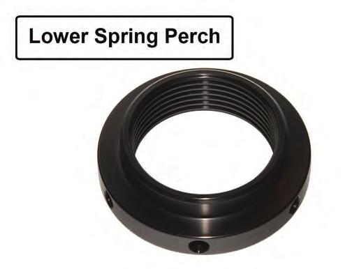
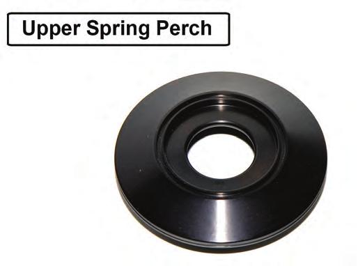
1 3430 Sacramento Dr., Unit D San Luis Obispo, CA Telephone: 805/ Fax: 805/ Front Coil-Over Kit, MMD-FCxxxxx Series (MMCO-24) Overlooked by other companies, our threaded sleeve assembly is designed to fit the strut snugly. A tight fit keeps the threaded sleeve from rattling on the strut. More importantly, the lower spring perch is kept square to the strut, preventing the spring from arcing and rubbing on the threaded sleeve. Finishing off the kit, we use only the highest quality springs on the market. Our extensive technical knowledge of rates, free lengths, and proper spring travel ensures that your car will perform to the max. We include dust boots to help protect your strut shaft from dirt and debris. Dirt and debris can damage seals and shorten the service life of your strut. Read all instructions before beginning work. Following instructions in the proper sequence will ensure the best and easiest installation. Thank you for purchasing Maximum Motorsports ultimate coil-over conversion kit manufactured specifically for MM Struts. There are many features that set our coil-over kit apart from the rest: Starting at the top, we maximize bump travel by providing an assortment of spacers to properly position the upper spring perch under the strut tower. Our upper spring perch assembly, shaped far better than others on the market, has been designed for optimum strength, clearance, and bump travel. Two O-rings seal the thrust needle bearings to keep dirt and water out, and the grease in. The lower spring perch is drilled for easy adjustment with a spanner wrench, if pre-loading the spring is necessary. A set screw ensures that the lower spring perch will never move. While other companies simply anodize their aluminum parts for appearance, we have critical components hard anodized, at over twice the cost, for maximum durability. With the use of a Coil-Over Kit, the entire front weight of the car is now transmitted through the pivot of your Caster/Camber (C/C) plates; you should use a well-designed steel C/C plate with a high-quality spherical bearing. Rubber or urethane C/C plate bushings will not be able to handle the load without excessive deformation and possible failure. Most aluminum C/C plates are not strong enough for coil-over applications. Aluminum C/C plates that are strong enough for use with a Coil-Over kit will be very thick and may unnecessarily reduce bump travel. The C/C plates only require three bolts because the strut top is captured within a triangle formed by these bolts (as viewed from the top). This means that each bolt carries a relatively equal portion of the vertical strut load, and the load is evenly distributed into the strut towers. For Mustangs, Maximum Motorsports makes the only C/C plate suitable for use with a Coil-Over kit: our innovative 4-bolt C/C plates. On cars, the strut top is outside of the triangle formed by the three factory mounting bolts (as viewed from the top). With a 3-bolt C/C plate the entire vertical load is carried by two bolts, and the plate is in a cantilevered bending situation. The load is unevenly distributed into the strut tower, resulting in a prying load which may bend the strut towers or result in failure of the C/C plates. MM added a fourth bolt, which results in the strut top being captured within the square formed by the four bolts (as viewed from the top). Now the load is evenly spread out into the strut towers. MMCO-24.indd 1 Copyright 2017 Maximum Motorsports, Inc.
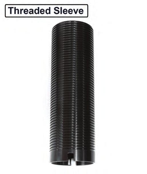
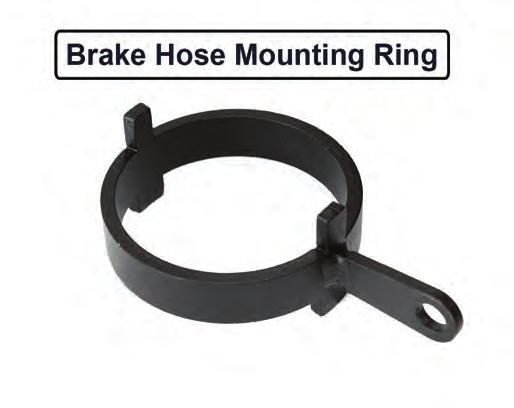
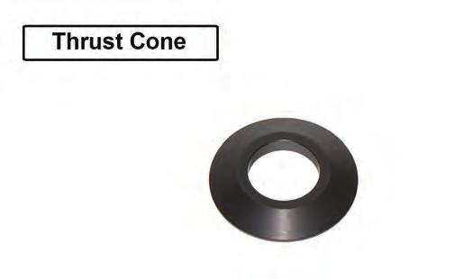
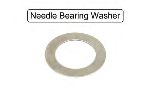
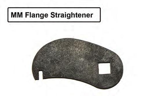
2 Read all instructions before beginning work. Following instructions in the proper sequence will ensure the best and easiest installation. Required Tools Floorjack Two jack stands Internal spring compressor 21mm wrench and 24mm 1/2 drive socket 2-3 1/2 drive extension Set of 3/8 drive shallow and deep metric sockets 3/8 drive ratchet Torque wrench with scale up to 160 ft-lbs. 8mm Allen wrench Small adjustable open end wrench (Crescent) Metal file Needlenose pliers Medium hammer Tape measure Mechanics/Dental mirror If the car has length FCAs, a drill and 1/8 drill bit will be required This Kit Contains: Description QTY Threaded Sleeve 2 Brake Hose Mounting Ring 2 Lower Spring Perch 2 Upper Spring Perch 2 Thrust Cone 2 Thrust Needle Bearing 2 Needle Bearing Washer 4 16mm ID x.12 long spacer bushing 2 16mm ID x.24 long spacer bushing 2 16mm ID x.48 long spacer bushing 4 7/8 ID x.5 long spacer bushing 2 17mm ID Thrust Washer 2 Thick O-ring 2 Thin O-ring 2 5/32 Allen wrench 1 Nylon-tip Set Screw 2 Dust Boot 2 Brake Hose Clamp 2 MM Flange Straightener 1 1/4-20 x 3/4 G5 zinc bolt 2 1/4-20 G5 zinc Nylock nut 2 1/4 SAE G8 flat yellow zinc washer 4 Installation Instructions 1 Required Supplemental Items Wheel bearing grease (Moly) Installation Time Shop: 2.5 Hours Home Mechanic: 4 Hours Copyright 2017 Maximum Motorsports, Inc. 2 MMCO-24.indd
3 Component Identification MMCO-24.indd 3 Copyright 2017 Maximum Motorsports, Inc.


4 Copyright 2017 Maximum Motorsports, Inc. 4 MMCO-24.indd


5 MMCO-24.indd 5 Copyright 2017 Maximum Motorsports, Inc.


6 Installation 1. Measure the front ride height to the top of the fender arch on both sides of the car. Record the measurements for future reference. 4. Unbolt the brake caliper assembly and hang it securely from the chassis. WARNING: Do NOT let the caliper hang from the brake hose, as this will cause unseen damage to the hose. 2. Loosen, but do not remove, the strut top retaining nuts. Then raise the front of the car and place it securely on jack stands. The car must be raised high enough on jack stands so that when the control arm pivots downwards to vertical, it will not touch the ground. 5. On vehicles, remove the front brake rotor. On vehicles, the rotor can remain on the spindle. 6. Disconnect the outer tie-rod end from the spindle. 3. Remove both front wheels. 7. Disconnect the swaybar end-link from the control arm. Copyright 2017 Maximum Motorsports, Inc. 6 MMCO-24.indd


7 8. If the car is equipped with ABS, carefully unhook the sensor s wire from the mounting bracket on the strut to get enough slack in the wire to remove the sensor from the spindle. Remove the sensor-to-spindle bolt, and carefully remove the sensor from the spindle. Remove the mounting bracket from the strut. 12. Remove the two bolts that hold the strut housing to the spindle, and carefully remove the strut from the car. 9. From the front of the car, place a floor jack under the control arm and slightly compress the spring to support the control arm when the strut top retaining nut is removed. 10. Loosen, but do not remove, the two bolts holding the strut housing to the spindle. 13. Carefully lower the control arm with the jack and remove the spring. If necessary, use a spring compressor. Often, aftermarket springs are shorter and can be gently popped out once the control arm is lowered far enough. Stock springs are quite long and require a spring compressor for safe removal. 11. Remove the strut top retaining nut. MMCO-24.indd 7 Copyright 2017 Maximum Motorsports, Inc.


8 14. Be sure to remove the upper spring isolator. Sometimes they stick to the upper spring perch. 15. On the inboard face of the driver side upper frame rail, there is an oval-shaped flange that protrudes from the frame rail. On cars with SN95 ( )-width front control arms, the coil-over spring may contact this flange, causing a clunking noise. The MM Flange Straightener can be used to bend the flange up, increasing clearance between it and the spring, and eliminating the potential interference. 16. Fit the MM Flange Straightener on a 3/8 drive ratchet as shown. Copyright 2017 Maximum Motorsports, Inc. 8 MMCO-24.indd


9 17. Fit the slotted end of the tool over the flange as shown. The flange can be bent by pushing down on the wrench. Reference the photo in the previous step to see where the tool needs to be used. NOTE: Do NOT attempt to bend the flange flush with the frame rail using the provided tool, as damage to the tool will occur. The tool is only designed to bend the flange ~50 from its starting position. If more clearance is needed, a small hammer can be used. 19. Check that the upper spring perch can slide down over the ring, which is located at the base of the threaded strut top. If it does not, file down the outside of the ring, being careful to remove material evenly to keep the ring circular. Note that there may be small divots on the outside of this ring. They should be filed down first. NOTE: The flange will bend easily, but we do NOT recommend attempting to bend the entire length in one step. Instead, bend the flange approximately 25, then move the tool forward along the flange in 1/4 increments until the required length of flange is bent. Then make another pass, bending the flange the remaining angle. Making smaller bends with the tool rather than one large one will minimize the risk of damaging the tool. NOTE: If the notch in the tool becomes enlarged, it can be hammered back to its original shape and size. 20. Once the Upper Spring Perch fits around the ring, remove it and clean all bare metal surfaces on the strut with a clean rag or paper towel. 21. Slide the Brake Hose Mounting Ring onto the strut. The shorter clocking tabs should face downwards and interlock with the mating notches on the strut housing. The brake hose mounting flange should point towards the rear of the vehicle. 18. Remove all hardware, dust boots, etc., from your MM struts. MMCO-24.indd 9 Copyright 2017 Maximum Motorsports, Inc.


10 22. Slide the threaded sleeve down over the strut housing, unthreaded end first, until the tabs on the Brake Hose Mounting Ring interlock with the notches on the bottom of the threaded sleeve. 26. Place the 2-1/2 diameter Coil-Over Spring onto the Lower Spring Perch. Position the Lower Spring Perch so the top of the spring is even with the top convolution in the dust boot. 23. If not already installed, thread the Lower Spring Perch onto the threaded sleeve. 24. Install the bellows-style dust boot onto the strut shaft. It should seat below the ring referenced in Step 19. NOTE: Check that the top of the dust boot has been trimmed down to the proper height, as shown below. If not, trim it enough (a power sander works well) so it seats below the ring referenced in Step Grease the thin O-ring and place it into the groove machined into the top surface of the Upper Spring Perch. 25. Use a Moly wheel bearing grease to lube the thick O- ring and slide it over the strut shaft until it rests on the top of the dust boot. Copyright 2017 Maximum Motorsports, Inc. 10 MMCO-24.indd


11 28. Place one Needle Bearing Washer into the recess on the top side of the Upper Spring Perch. Completely pack the Thrust Needle Bearing with a high-quality Moly wheel bearing grease. Place the Thrust Needle Bearing on top of the installed Needle Bearing Washer. Place the second Needle Bearing Washer on top of the Thrust Needle Bearing. 29. Grease the bottom of the Thrust Cone where it will contact the thin O-ring from Step 27 and place it on top of the upper spring perch assembly. 30. Slide the completed Upper Spring Perch Assembly down over the top of the strut shaft until it rests on the thick O-ring. MMCO-24.indd 11 Copyright 2017 Maximum Motorsports, Inc.


12 31. Slide the large 7/8 inside diameter Spacer Bushing over the strut shaft until it rests on the Thrust Cone. NOTE: Some companies C/C plates have a fixed-type spacer bushing pressed into the spherical bearing. With these types of C/C plates, and you may not be able to maximize bump travel in Step Take one of the provided 16mm ID x.48 long spacers and place it over the strut shaft. Slide it down until it sits on top of the Thrust Washer. 32. Place the 17mm inside diameter Thrust Washer over the top of the strut shaft. Don t be surprised if the Thrust Washer will not contact the shoulder of the shaft. The thick O-ring from Step 25 will be compressed and expanded during installation, and the Thrust Washer will then contact the shoulder of the strut shaft. NOTE: Install C/C plates if the car is not equipped with them at this time. Copyright 2017 Maximum Motorsports, Inc. 12 MMCO-24.indd


13 34. Take the entire strut assembly to the car and place the strut shaft top into the spherical bearing of the C/C plate. While holding the strut assembly as high as it will go in the C/C bearing, stack a.12,.24 and.48 long 16mm ID spacer on top of the strut shaft. Tighten the strut top retaining nut to a snug setting. NOTE: C/C plate not installed in car for visibility. Assembly and the bottom of the C/C plate. The tightest spot will be toward the rearward bolt heads on the C/C plate bottom plates. Check clearance at full droop while the suspension is being steered. Jack the control arm up to ride height and check for clearance while the suspension is being steered. The minimum clearance should be between 1/8 to 1/4. TIP: Remember that the relative position of the Upper Spring Perch will change with different front end alignment settings. Be sure to allow clearance for any future caster/camber settings you may use. A small mirror will be necessary to check all clearances. NOTE: Spring and dust boot not shown for clarity. 35. If the alignment has not been set, the caster must be roughly estimated before continuing. If using MM C/C plates: For Mustangs, slide the bearing cup of the C/C plate as far as it will go toward the firewall and torque to 32 lb-ft. For Mustangs, slide the bearing cup of the C/C plate in the middle of its caster adjustment range and torque to 32 lb-ft. 36. Slide the strut ears over the spindle ear, install both mounting bolts, and loosely thread on both nuts. 37. Loosely reattach the outer tie-rod to the steering arm on the spindle. 38. Check clearance between the Upper Spring Perch MMCO-24.indd 13 Copyright 2017 Maximum Motorsports, Inc.
 from the Upper Spacer Stack to the Lower Spacer Stack to gain necessary")
14 39. The vertical position of the Upper Spring Perch Assembly is adjusted by exchanging spacers between the upper and lower spacer stacks (see photo below). If the tightest clearance is less than 1/8, move the next appropriate Spacer Bushing (or combination of Spacer Bushings) from the Upper Spacer Stack to the Lower Spacer Stack to gain necessary clearance. If clearance is in excess of 1/4, use the next appropriate thinner Spacer Bushing (or combination of Spacer Bushings) to reduce the clearance and gain as much bump travel as possible. Whether you choose the maximum negative or maximum positive position is a function of other suspension parts on your car. See the charts below for suggested spindle orientation settings. Spindle Year Mustang Front Control Arm Model Ford or MMFCA for Ford or MMFCA for Negative Positive Negative Positive Mustang Auto-X or Road Race Use Drag Race or Street Use Negative Positive 40. After the proper combination of Spacer Bushings to place underneath the C/C plate has been determined, secure the strut shaft to the C/C plate with the strut top retaining nut. At a minimum, one Spacer Bushing is required between the spherical bearing and the strut top retaining nut. Wait until the car is on the ground to torque the retaining nut. NOTE: All the provided Spacer Bushings must be installed on the struts. They are required to prevent the strut top nut from running out of threads when tightening. 42. To position the spindle in the maximum negative position, push the strut housing inwards, near the spindle mounting ears, while tightening the strut-to-spindle bolts. To position the spindle in the maximum positive position, pull the strut housing outwards, near the spindle mounting ears, while tightening the strut-to-spindle bolts. Torque the strut-to-spindle bolts to 192 lb-ft. 43. Torque the outer tie-rod nut to factory specification and install a new cotter pin. 44. Do your first check for potential interference between the coil-over spring, and the brake hose where it attaches to the hard line. Use the jack to move the suspension from full droop to full bump, and check while someone moves the steering wheel back and forth cars usually do not have any interference problems, but cars or any car using length front control arms may require relocating the brake hard-line mounting bracket rearward 1. (Refer to addendum at the end of these instructions.) 41. The MM struts have a larger bottom bolt hole in the strut-mounting ear to allow for production variations in NOTE: In rare cases there may be an interference between the location of the holes in the spindles. This enlarged the Spring/Lower Spring Perch and the stock K- hole allows the spindle orientation, relative to the strut, member near where the stock spring was located. To to be changed by 1.4 degrees, before the bolts are remedy that situation you will need a hand-held grinder tightened. This provides 1.4 degrees of camber adjustment to clearance the K-member. After the installation is at the strut-to-spindle interface. It is important complete, with final ride height set, another check for to tighten this joint with the spindle held in either the interference between components must be made. maximum positive or maximum negative camber position on both sides of the car. This way, when you 45. Adjust the height of the Lower Spring Perch. If the disassemble the front suspension in the future, it will installed Spring has a rate of between 150 and 200lbs/ not be necessary to realign the car if you reassemble in, adjust the height of the Lower Spring Perch so that it with the spindle in the same maximum positive or the top of the Spring just touches the bottom of the maximum negative position relative to the strut ears. Upper Spring Perch. If the installed Spring has a rate of between 225 and 325lbs/in, adjust the Lower Spring Copyright 2017 Maximum Motorsports, Inc. 14 MMCO-24.indd


, the Spring may not touch the Upper Spring Perch when the suspension is")


15 Perch so that the top of the Spring is about 1.25 from the Upper Spring Perch. If the installed Spring is stiffer than 325lbs/in, adjust the Lower Spring Perch so that the top of the Spring is about 2 from the Upper Spring Perch. 49. Reattach the mounting bracket to the spindle and adjust the bends if necessary to keep the mounting bracket close to the strut. Install and tighten the retaining nut for the mounting bracket. NOTE: When using stiffer Springs (greater than about 200lbs/in), the Spring may not touch the Upper Spring Perch when the suspension is at full droop travel (car raised up off of the ground by the frame so that the tires are in the air). This is normal and does not indicate any problem with the installation. Changing to a different length Spring will NOT have any affect on this. If you have questions about this, contact Maximum Motorsports Tech department. 46. If the car has ABS, the mounting bracket for the sensor will need to be modified to clear the Lower Spring Perch. 50. Clean any dirt from the tip of the ABS sensor and reattach the ABS sensor to the spindle. Reattach the sensor s wire to the mounting bracket. 47. Use two sets of pliers to hold and bend the bracket forward near the base. 48. Then carefully bend it upward near the end where the wire attaches. MMCO-24.indd 15 Copyright 2017 Maximum Motorsports, Inc.
: The stack-up for the Brake Hose Clamp hardware is shown below. 52. If you removed the brake rotor, reinstall it now. 53.")

: Slide the Brake Hose Clamp onto the hose as shown. 57.")
: Pass the bolt through the Brake Hose Tab, place a washer onto the bolt, and secure the bolt with the Nylock nut.")
16 51. Reattach the swaybar end-link to the control arm. Do not overtighten the end-link bushings. 56. (Flexible Hoses ONLY): The stack-up for the Brake Hose Clamp hardware is shown below. 52. If you removed the brake rotor, reinstall it now. 53. Reattach the brake caliper and torque the mounting bolts to factory specifications. 54. If using a brake hose that has a long tubular metal section attached to the banjo fitting, skip to Step 59. This type of hose will not work with the Brake Hose Tab mounting feature. 55. (Flexible Hoses ONLY): Slide the Brake Hose Clamp onto the hose as shown. 57. (Flexible Hoses ONLY): Place a washer under the head of the bolt and slide it through the Brake Hose Clamp. 58. (Flexible Hoses ONLY): Pass the bolt through the Brake Hose Tab, place a washer onto the bolt, and secure the bolt with the Nylock nut. WARNING: The brake hose end that attaches to the caliper may need to be reclocked in order to provide enough slack in the hose to attach the Brake Hose Clamp to the Brake Hose Tab. If reclocked, the front brakes must be bled per the factory manual. Copyright 2017 Maximum Motorsports, Inc. 16 MMCO-24.indd
17 59. Mount the tire and wheel. Check for clearance to the Coil-Over components. Minimum clearance between the tire or wheel and any of the coil-over components is 1/8. Remember that the final ride height has not yet been set, and so the position of the Lower Spring Perch may change. 60. Lower the car to the ground. Torque the lug nuts to factory specifications. 61. Torque the strut shaft retaining nut to 65 lb-ft. 62. Roll the car back and forth to settle the suspension. 63. Measure the ride height, as in Step 1. Adjust the ride height to match the previous measurement, or change the ride height as desired. 64. To change ride height, carefully jack the front of the car up and place it on jack stands. Rotate the Lower Spring Perch to raise the car up or down. NOTE: The distance from the bottom of the lower spring perch, to the bottom of the threaded sleeve, on each side of the car must be the same. If these distances on each side of the car are set differently, in an attempt to level the car, the corner weights will most likely end up very unequal. This will result in poor handling and other problems. If you are attempting to make the ride heights on both sides of the car perfectly equal, take the car to a shop that specializes in road race or autocross setups and has corner weight scales. NOTE: Spring rates 200 lbs/in and lower usually need to be preloaded to achieve a proper ride height. The MMT-2 Spanner Wrench (available separately) is designed to help rotate the Lower Spring Perch in these cases. 65. After the ride height is set, tighten the set screw a little at a time until it takes some resistance to rotate the Lower Spring Perch on the Threaded Sleeve. Only a very small amount of friction is needed to keep the lower spring perch from rotating. Any extra force on the set screw will result in damage to the Nylon tip and the Threaded Sleeve. 66. Have the front end professionally aligned. Remember that any time the ride height is changed, the camber and toe settings will have to be adjusted. MMCO-24.indd 17 Copyright 2017 Maximum Motorsports, Inc.

 Follow the instructions below to relocate the bracket. Passenger side shown. 1. Remove the retaining clip that holds the brake hose in the brake line bracket. (Figure 1) 2.")
 3.")

18 3430 Sacramento Dr., Unit D San Luis Obispo, CA Telephone: 805/ Fax: 805/ Brake Line Relocation Addendum, ONLY This addendum is for Mustangs that have interference between the Coil Spring or Lower Spring Perch and the brake line bracket, after installing the MMCO-1, MMCO-2, or MMCO-24 front coilover kits. 4. Mark the new screw location for the brake line bracket. (Figure 2) Follow the instructions below to relocate the bracket. Passenger side shown. 1. Remove the retaining clip that holds the brake hose in the brake line bracket. (Figure 1) 2. Remove the 8mm hex-head size mounting screw retaining the brake line bracket to the frame rail. (Figure 1) 5. Move the brake line bracket out of the way and drill a 1/8 diameter hole on the mark made in Step 4. (Figure 3) 3. Slide the mounting tab rearward approximately 1 until the small clocking tab is resting in the nearest existing hole in the frame rail. (Figure 2) 6. Reattach the brake line mounting bracket to the frame rail in its new location and tighten the mounting screw. 7. Reinstall the brake hose retaining clip. NOTE: The brake lines may need to be adjusted slightly to accommodate the new position of the brake line bracket. The lines can be easily bent the small amount needed by hand; no tubing bender is necessary. 8. Repeat Steps 1-7 for the driver side bracket. Copyright 2017 Maximum Motorsports, Inc. 18 MMCO-24.indd
MM Rear Coil-Over Kit - Koni Single and Double Adjustable Shocks (MMCO-5)
") 3430 Sacramento Dr., Unit D San Luis Obispo, CA 93401 Telephone: 805/544-8748 Fax: 805/544-8645 www.maximummotorsports.com MM Rear Coil-Over Kit - Koni Single and Double Adjustable Shocks (MMCO-5) Read
3430 Sacramento Dr., Unit D San Luis Obispo, CA 93401 Telephone: 805/544-8748 Fax: 805/544-8645 www.maximummotorsports.com MM Rear Coil-Over Kit - Koni Single and Double Adjustable Shocks (MMCO-5) Read
MM Rear Coil-Over Kit - Bilstein Shocks (MMCO-3)
") 3430 Sacramento Dr., Unit D San Luis Obispo, CA 93401 Telephone: 805/544-8748 Fax: 805/544-8645 www.maximummotorsports.com MM Rear Coil-Over Kit - Bilstein Shocks (MMCO-3) Read all instructions before
3430 Sacramento Dr., Unit D San Luis Obispo, CA 93401 Telephone: 805/544-8748 Fax: 805/544-8645 www.maximummotorsports.com MM Rear Coil-Over Kit - Bilstein Shocks (MMCO-3) Read all instructions before
MM IRS Coil-Over Kit - Bilstein/MM Shocks (MMCO-4)
") 3430 Sacramento Dr., Unit D San Luis Obispo, CA 93401 Telephone: 805/544-8748 Fax: 805/544-8645 www.maximummotorsports.com MM IRS Coil-Over Kit - Bilstein/MM Shocks (MMCO-4) The lower spring perch is drilled
3430 Sacramento Dr., Unit D San Luis Obispo, CA 93401 Telephone: 805/544-8748 Fax: 805/544-8645 www.maximummotorsports.com MM IRS Coil-Over Kit - Bilstein/MM Shocks (MMCO-4) The lower spring perch is drilled
Coil-Over Kit, MMD-RC1xxxx Shock (MMCO-23)
") 3430 Sacramento Dr., Unit D San Luis Obispo, CA 93401 Telephone: 805/544-8748 Fax: 805/544-8645 www.maximummotorsports.com Coil-Over Kit, MMD-RC1xxxx Shock (MMCO-23) Supplemental Installation Notes This
3430 Sacramento Dr., Unit D San Luis Obispo, CA 93401 Telephone: 805/544-8748 Fax: 805/544-8645 www.maximummotorsports.com Coil-Over Kit, MMD-RC1xxxx Shock (MMCO-23) Supplemental Installation Notes This
MM Caster/Camber Plates, (Mm5CC-7)
") 3430 Sacramento Dr., Unit D San Luis Obispo, CA 93401 Telephone: 805/544-8748 Fax: 805/544-8645 www.maximummotorsports.com MM Caster/Camber Plates, 2005-14 (Mm5CC-7) Supplemental Installation Notes This
3430 Sacramento Dr., Unit D San Luis Obispo, CA 93401 Telephone: 805/544-8748 Fax: 805/544-8645 www.maximummotorsports.com MM Caster/Camber Plates, 2005-14 (Mm5CC-7) Supplemental Installation Notes This
MM Caster/Camber Plates, (MMCC7989)
") 3430 Sacramento Dr., Unit D San Luis Obispo, CA 93401 Telephone: 805/544-8748 Fax: 805/544-8645 www.maximummotorsports.com MM Caster/Camber Plates, 1979-89 (MMCC7989) IMPORTANT: The bearing used in our
3430 Sacramento Dr., Unit D San Luis Obispo, CA 93401 Telephone: 805/544-8748 Fax: 805/544-8645 www.maximummotorsports.com MM Caster/Camber Plates, 1979-89 (MMCC7989) IMPORTANT: The bearing used in our
Coil-Over Kit, MMD-RC1xxxx Shock (MMCO-22)
") 3430 Sacramento Dr., Unit D San Luis Obispo, CA 93401 Telephone: 805/544-8748 Fax: 805/544-8645 www.maximummotorsports.com Coil-Over Kit, MMD-RC1xxxx Shock (MMCO-22) Supplemental Installation Notes This
3430 Sacramento Dr., Unit D San Luis Obispo, CA 93401 Telephone: 805/544-8748 Fax: 805/544-8645 www.maximummotorsports.com Coil-Over Kit, MMD-RC1xxxx Shock (MMCO-22) Supplemental Installation Notes This
Coil-Over Kit, MMD-RC0xxxx Shock (MMCO-20)
") 3430 Sacramento Dr., Unit D San Luis Obispo, CA 93401 Telephone: 805/544-8748 Fax: 805/544-8645 www.maximummotorsports.com Coil-Over Kit, MMD-RC0xxxx Shock (MMCO-20) Supplemental Installation Notes OEM
3430 Sacramento Dr., Unit D San Luis Obispo, CA 93401 Telephone: 805/544-8748 Fax: 805/544-8645 www.maximummotorsports.com Coil-Over Kit, MMD-RC0xxxx Shock (MMCO-20) Supplemental Installation Notes OEM
US Patent You will find many features that set our Caster/Camber Plates apart from the rest.
 3430 Sacramento Dr., Unit D San Luis Obispo, CA 93401 Telephone: 805/544-8748 Fax: 805/544-8645 www.maximummotorsports.com US Patent 6485223 Read all instructions before beginning work. Following instructions
3430 Sacramento Dr., Unit D San Luis Obispo, CA Telephone: 805/ Fax: 805/
 3430 Sacramento Dr., Unit D San Luis Obispo, CA 93401 Telephone: 805/544-8748 Fax: 805/544-8645 www.maximummotorsports.com MM Caster/Camber Plates, 2005-10 (Mm5CC-1) Read all instructions before beginning
2. Remove front wheels.
 Read all instructions before beginning work. Following instructions in the proper sequence will ensure the best and easiest installation. Thank you for purchasing Maximum Motorsports Caster/Camber Plates.
2011+ Adjustable Tie-rod Ends (Mm5TR-2)
") 3430 Sacramento Dr., Unit D San Luis Obispo, CA 93401 Telephone: 805/544-8748 Fax: 805/544-8645 www.maximummotorsports.com 2011+ Adjustable Tie-rod Ends (Mm5TR-2) Instructions 1. Set the parking brake
3430 Sacramento Dr., Unit D San Luis Obispo, CA 93401 Telephone: 805/544-8748 Fax: 805/544-8645 www.maximummotorsports.com 2011+ Adjustable Tie-rod Ends (Mm5TR-2) Instructions 1. Set the parking brake
MM Caster Camber Plates, (Mm6CC-10)
") 3430 Sacramento Dr., Unit D San Luis Obispo, CA 93401 Telephone: 805/544-8748 Fax: 805/544-8645 www.maximummotorsports.com MM Caster Camber Plates, 2015+ (Mm6CC-10) Read all instructions before beginning
3430 Sacramento Dr., Unit D San Luis Obispo, CA 93401 Telephone: 805/544-8748 Fax: 805/544-8645 www.maximummotorsports.com MM Caster Camber Plates, 2015+ (Mm6CC-10) Read all instructions before beginning
Adjustable Tie-rod Ends (Mm5TR-1)
") 3430 Sacramento Dr., Unit D San Luis Obispo, CA 93401 Telephone: 805/544-8748 Fax: 805/544-8645 www.maximummotorsports.com 2005-10 Adjustable Tie-rod Ends (Mm5TR-1) 3. Remove the front wheels. 4. Loosen
3430 Sacramento Dr., Unit D San Luis Obispo, CA 93401 Telephone: 805/544-8748 Fax: 805/544-8645 www.maximummotorsports.com 2005-10 Adjustable Tie-rod Ends (Mm5TR-1) 3. Remove the front wheels. 4. Loosen
J&M CASTER/CAMBER PLATE INSTALLATION INSTRUCTIONS (#24213) Hardware:
 Hardware:") J&M CASTER/CAMBER PLATE INSTALLATION INSTRUCTIONS (#24213) Thank you for purchasing J&M Product s Caster/Camber Plates (#24213) for 1994-2004 Ford Mustang. The J&M Caster/Camber plates are the highest
J&M CASTER/CAMBER PLATE INSTALLATION INSTRUCTIONS (#24213) Thank you for purchasing J&M Product s Caster/Camber Plates (#24213) for 1994-2004 Ford Mustang. The J&M Caster/Camber plates are the highest
MM Adjustable IRS Tie-Rod (MMIRSTR-2)
") 3430 Sacramento Dr., Unit D San Luis Obispo, CA 93401 Telephone: 805/544-8748 Fax: 805/544-8645 www.maximummotorsports.com MM Adjustable IRS Tie-Rod (MMIRSTR-2) Sample Bumpsteer Curve: Read all instructions
3430 Sacramento Dr., Unit D San Luis Obispo, CA 93401 Telephone: 805/544-8748 Fax: 805/544-8645 www.maximummotorsports.com MM Adjustable IRS Tie-Rod (MMIRSTR-2) Sample Bumpsteer Curve: Read all instructions
Maximum Motorsports Camber Caster Plates (05-10):
:") Maximum Motorsports Camber Caster Plates (05-10): Tools Required: Lug Wrench 21mm Deep Socket 18mm Deep Socket 15mm Deep Socket 17mm Socket 13mm Socket 10mm Socket Torque Wrench (requires 166lb-ft capacity
Maximum Motorsports Camber Caster Plates (05-10): Tools Required: Lug Wrench 21mm Deep Socket 18mm Deep Socket 15mm Deep Socket 17mm Socket 13mm Socket 10mm Socket Torque Wrench (requires 166lb-ft capacity
Cobra IRS Aluminum Differential Bushings (MMIRSB-40.2)
") 3430 Sacramento Dr., Unit D San Luis Obispo, CA 93401 Telephone: 805/544-8748 Fax: 805/544-8645 www.maximummotorsports.com Cobra IRS Aluminum Differential Bushings (MMIRSB-40.2) The MM front differential
3430 Sacramento Dr., Unit D San Luis Obispo, CA 93401 Telephone: 805/544-8748 Fax: 805/544-8645 www.maximummotorsports.com Cobra IRS Aluminum Differential Bushings (MMIRSB-40.2) The MM front differential
2005-Pres. Ford Mustang Camber Plate Installation Instructions:
 2005-Pres. Ford Mustang Camber Plate Installation Instructions: J&M Products once again outdoes our competitors with these fully adjustable PATENT PENDING Camber & Caster plate assemblies for the 2005-2010
Global West Suspension 655 South Lincoln Ave San Bernardino Ca Phone Fax Web address globalwest.
 Global West Suspension 655 South Lincoln Ave San Bernardino Ca. 92408 Phone 877-470-2975 Fax 909-890-0703 Web address globalwest.net Mustang coilover instruction sheets for 64-66 Kit includes the following
Installations Instructions for Maier Racing Front Coilover Kit MS Ford Mustang
 22215 Meekland Avenue Hayward, CA 94541 Phone: (510) 581-7600 Fax: (510) 581-2406 Installations Instructions for Maier Racing Front Coilover Kit MS-02-001 1964-1973 Ford Mustang Contents Front Coilover
Mustang. MOD1 Coilover Kit FXXADK0100, FXXADK0200, FXXADK0400 FXXA1K0100, FXXA1K0200, FXXA1K0400
 1964.5-1973 Mustang MOD1 Coilover Kit FXXADK0100, FXXADK0200, FXXADK0400 FXXA1K0100, FXXA1K0200, FXXA1K0400 2276 Research Dr. Livermore, Ca 94550 Ph: (925)-443-6300 E: maier@mikemaierinc.com Page 1 of
Maximum Motorsports Caster/Camber Plates Installation Guide (94-04)
") Maximum Motorsports Caster/Camber Plates Installation Guide (94-04) The below installation instructions work for the following products: Maximum Motorsports Caster/Camber Plates (94-04) Please read through
Maximum Motorsports Caster/Camber Plates Installation Guide (94-04) The below installation instructions work for the following products: Maximum Motorsports Caster/Camber Plates (94-04) Please read through
MM Tubular K-Member, (Mm5KM-7)
") 3430 Sacramento Dr., Unit D San Luis Obispo, CA 93401 Telephone: 805/544-8748 Fax: 805/544-8645 www.maximummotorsports.com MM Tubular K-Member, 2005-14 (Mm5KM-7) This Kit Contains Congratulations on purchasing
3430 Sacramento Dr., Unit D San Luis Obispo, CA 93401 Telephone: 805/544-8748 Fax: 805/544-8645 www.maximummotorsports.com MM Tubular K-Member, 2005-14 (Mm5KM-7) This Kit Contains Congratulations on purchasing
MM Brake Line Kit for Fox-IRS Swap (MMBAK-21)
") 3430 Sacramento Dr., Unit D San Luis Obispo, CA 93401 Telephone: 805/544-8748 Fax: 805/544-8645 www.maximummotorsports.com MM Brake Line Kit for Fox-IRS Swap (MMBAK-21) Supplemental Installation Notes
3430 Sacramento Dr., Unit D San Luis Obispo, CA 93401 Telephone: 805/544-8748 Fax: 805/544-8645 www.maximummotorsports.com MM Brake Line Kit for Fox-IRS Swap (MMBAK-21) Supplemental Installation Notes
MM Brake Hose Kit (MMBK13R)
") 3430 Sacramento Dr., Unit D San Luis Obispo, CA 93401 Telephone: 805/544-8748 Fax: 805/544-8645 www.maximummotorsports.com MM Brake Hose Kit (MMBK13R) Read all instructions before beginning work. Following
3430 Sacramento Dr., Unit D San Luis Obispo, CA 93401 Telephone: 805/544-8748 Fax: 805/544-8645 www.maximummotorsports.com MM Brake Hose Kit (MMBK13R) Read all instructions before beginning work. Following
Maximum Motorsports Caster/Camber Plates (03-04 Cobra) - Installation Instructions
 - Installation Instructions") Maximum Motorsports Caster/Camber Plates (03-04 Cobra) - Installation Instructions The below installation instructions work for the following products: Maximum Motorsports Caster/Camber Plates (03-04 Cobra)
Maximum Motorsports Caster/Camber Plates (03-04 Cobra) - Installation Instructions The below installation instructions work for the following products: Maximum Motorsports Caster/Camber Plates (03-04 Cobra)
MM Brake Line Kit (MMBK14R)
") 3430 Sacramento Dr., Unit D San Luis Obispo, CA 93401 Telephone: 805/544-8748 Fax: 805/544-8645 www.maximummotorsports.com MM Brake Line Kit (MMBK14R) Read all instructions before beginning work. Following
3430 Sacramento Dr., Unit D San Luis Obispo, CA 93401 Telephone: 805/544-8748 Fax: 805/544-8645 www.maximummotorsports.com MM Brake Line Kit (MMBK14R) Read all instructions before beginning work. Following
MM Panhard Bar, Mustang (MMPBA)
") 3430 Sacramento Dr., Unit D San Luis Obispo, CA 93401 Telephone: 805/544-8748 Fax: 805/544-8645 www.maximummotorsports.com MM Panhard Bar, 1979-98 Mustang (MMPBA) Important Note for Customers with Baer
3430 Sacramento Dr., Unit D San Luis Obispo, CA 93401 Telephone: 805/544-8748 Fax: 805/544-8645 www.maximummotorsports.com MM Panhard Bar, 1979-98 Mustang (MMPBA) Important Note for Customers with Baer
Installation Instructions
 Installation Instructions Eibach Springs, Inc. 264 Mariah Circle Corona, California 92879-1751 USA Tech Support 800-222-8811 Ext 114 CASTER / CAMBER PLATE KIT # 5.3518K 1999-2004 SN95 Ford Mustang - All
MM K-Member, chassis with 4.6 engine (MMKM-2.1)
") 3430 Sacramento Dr., Unit D San Luis Obispo, CA 93401 Telephone: 805/544-8748 Fax: 805/544-8645 www.maximummotorsports.com MM K-Member, 1979-95 chassis with 4.6 engine (MMKM-2.1) most rigid, and yet our
3430 Sacramento Dr., Unit D San Luis Obispo, CA 93401 Telephone: 805/544-8748 Fax: 805/544-8645 www.maximummotorsports.com MM K-Member, 1979-95 chassis with 4.6 engine (MMKM-2.1) most rigid, and yet our
PPM-8023 / PPM-8043 JEEP JK SYNERGY STAGE 3 SUSPENSION SYSTEM Version 1
 SYNERGY MFG. 870 INDUSTRIAL WAY, SAN LUIS OBISPO, CA (805) 242-0397 PPM-8023 / PPM-8043 JEEP JK SYNERGY STAGE 3 SUSPENSION SYSTEM Version 1 GENERAL NOTES: These instructions are also available on our website;
PPM-8022 / PPM-8042 JEEP JK STAGE 2 SYNERGY SUSPENSION SYSTEM Version 1
 POLY PERFORMANCE MFG. 870 INDUSTRIAL WAY, SAN LUIS OBISPO, CA (805) 242-0397 PPM-8022 / PPM-8042 JEEP JK STAGE 2 SYNERGY SUSPENSION SYSTEM Version 1 GENERAL NOTES: These instructions are also available
MM K-Member, chassis with 5.0L engine (MMKM-1.1)
") 3430 Sacramento Dr., Unit D San Luis Obispo, CA 93401 Telephone: 805/544-8748 Fax: 805/544-8645 www.maximummotorsports.com Read all instructions before beginning work. Following instructions in the proper
3430 Sacramento Dr., Unit D San Luis Obispo, CA 93401 Telephone: 805/544-8748 Fax: 805/544-8645 www.maximummotorsports.com Read all instructions before beginning work. Following instructions in the proper
Part # Camber Caster Plates Ford Mustang All Ford Mustang GT500
 Part # 24220 Camber Caster Plates 2005-2010 Ford Mustang All 2007-2014 Ford Mustang GT500 J&M Products once again outdoes our competitors with these fully adjustable (Protected under US Patent No. 8,820,759
INSTALLATION INSTRUCTIONS
 INSTALLATION INSTRUCTIONS 2005-2012 Nissan Xterra/Frontier / Pathfinder PART NUMBERS: NP17500, NP17525, NP17550 FRONTIER PARTS & CORRESPONDING HARDWARE LIST XTERRA PATHFINDER ABOVE LISTED 1/2 Metal Lock
MM K-Member, chassis w/4.6l engine & Hellion Turbo Kit (MMKM-3.1)
") 3430 Sacramento Dr., Unit D San Luis Obispo, CA 93401 Telephone: 805/544-8748 Fax: 805/544-8645 www.maximummotorsports.com MM K-Member, 1979-95 chassis w/4.6l engine & Hellion Turbo Kit (MMKM-3.1) Proper
3430 Sacramento Dr., Unit D San Luis Obispo, CA 93401 Telephone: 805/544-8748 Fax: 805/544-8645 www.maximummotorsports.com MM K-Member, 1979-95 chassis w/4.6l engine & Hellion Turbo Kit (MMKM-3.1) Proper
MM Heavy Duty Torque-arm (MMTA-3 & -4) Engine Torque Table 4.56: : :
 Engine Torque Table 4.56: : :") 3430 Sacramento Dr., Unit D San Luis Obispo, CA 93401 Telephone: 805/544-8748 Orders Only: 800/839-0928 Fax: 805/544-8645 The ultimate rear suspension for your Mustang is now available from Maximum Motorsports.
3430 Sacramento Dr., Unit D San Luis Obispo, CA 93401 Telephone: 805/544-8748 Orders Only: 800/839-0928 Fax: 805/544-8645 The ultimate rear suspension for your Mustang is now available from Maximum Motorsports.
Installation Instructions
 Installation Instructions Eibach Springs, Inc. 264 Mariah Circle Corona, California 92879-1751 USA Tech Support 800-222-8811 Ext 114 CASTER / CAMBER PLATE KIT # 5.3510K 1990-1993 Ford Mustang All FOX Body
IRS Racing Brake Kit (MMBAK-15, -16)
") 3430 Sacramento Dr., Unit D San Luis Obispo, CA 93401 Telephone: 805/544-8748 Fax: 805/544-8645 www.maximummotorsports.com IRS Racing Brake Kit (MMBAK-15, -16) Floating rotors (MMBAK-16 ONLY) can move
3430 Sacramento Dr., Unit D San Luis Obispo, CA 93401 Telephone: 805/544-8748 Fax: 805/544-8645 www.maximummotorsports.com IRS Racing Brake Kit (MMBAK-15, -16) Floating rotors (MMBAK-16 ONLY) can move
Manual Brake Conversion Kit, (MMBAK-13)
") 3430 Sacramento Dr., Unit D San Luis Obispo, CA 93401 Telephone: 805/544-8748 Fax: 805/544-8645 www.maximummotorsports.com Manual Brake Conversion Kit, 1994-95 (MMBAK-13) The MM kit includes a CNC machined
3430 Sacramento Dr., Unit D San Luis Obispo, CA 93401 Telephone: 805/544-8748 Fax: 805/544-8645 www.maximummotorsports.com Manual Brake Conversion Kit, 1994-95 (MMBAK-13) The MM kit includes a CNC machined
Part # Mustang Complete HQ Series Coil-Over Kit
 350 S. St. Charles St. Jasper, In. 47546 Ph. 812.482.2932 Fax 812.634.6632 www.ridetech.com Front Components: Part # 12090210 64-66 Mustang Complete HQ Series Coil-Over Kit 1 12093509 HQ Series Front Coil-Overs
AEV30308AA Last Updated: 05/31/18. 4 DUALSPORT sc SUSPENSION system for RAM 1500 air ride standard and rebel INSTALLATION GUIDE
 AEV30308AA Last Updated: 05/31/18 4 DUALSPORT sc SUSPENSION system for RAM 1500 air ride standard and rebel INSTALLATION GUIDE PLEASE READ BEFORE YOU START TO GUARANTEE A QUALITY INSTALLATION, WE RECOMMEND
Camaro Camber Kit Installation
 Camaro Camber Kit Installation Part Name: Camaro Camber Kit Part Number: 1410120/1410111 Application: 2010 + Chevrolet Camaro V8 and V6 Level of Difficulty: Moderate Expected Installation Time: 2 Hours
Installation Notes: #86000-R Race Series +3.5 L/T Kit
 159 North Maple St. Unit J, CORONA CA 92880 P. 951-737-9682 F. 951-737-9006 WWW.CHAOSFAB.COM Installation Notes: #86000-R Race Series +3.5 L/T Kit Factory manual is recommended for removal and re-installation
RHINO SUSPENSION SYSTEM INSTALLATION INSTRUCTIONS
 PARTS INCLUDED: 2 FRONT UPPER A-ARMS 2 FRONT LOWER A-ARMS 2 UNI-BALL JOINTS 2 UNI-BALL JOINT STUDS 2 UNI-BALL JOINT CAPS 2 RETAINING RINGS 1 FRONT SHOCK ASSEM. 2 DELRON STEERING STOPS 2 SHOCK MOUNT SPACERS
'99-03 CHEVROLET/GMC IFS 4WD 6" SUSPENSION SYSTEM P/N INSTALLATION INSTRUCTIONS
 1/16/04 '99-03 CHEVROLET/GMC IFS 4WD 6" SUSPENSION SYSTEM P/N. 10-41099 INSTALLATION INSTRUCTIONS NOTE: Each Lift Kit and options to Lift Kits are packaged separately. Therefore, installation procedures
M-Force E36 Camber Plate Installation
 Thank you for purchasing the Adjustable Camber Plate kit from Vorshlag Motorsports. In order to ensure proper installation and longevity of your kit, Vorshlag Motorsports recommends that you have your
INSTALLATION GUIDE Bolt-On Drag-Race Strut Clip Chevy II
 INSTALLATION GUIDE 7702 Bolt-On Drag-Race Strut Clip 1962-67 Chevy II Description: STRUT CLIP 4130 BOLT ON 62-67 CHEVY II, INCLUDES 4130 ROUND TUBE FRAME CLIP, DOUBLE-ADJUSTABLE STRUTS, ADJUSTABLE-HEIGHT
KIT # CSS-C SUSPENSION LIFT KIT
 14385 Veterans Way Moreno Valley, CA 92553 Phone: (951) 571-0212 Fax: (951) 571-0215 2001-2010 CHEVROLET SILVERADO 1500 AND 2500 HD 4WD AND 2WD PICK-UP 1999-2010 CHEVY 2500 4WD PICK-UPS 2001-2010 2500
»Product» Safety Warning
 D1401 Installation Instructions 2013 Ram 3500, 2014 Ram 2500 4.5" Radius Arm Suspension Lift Read and understand all instructions and warnings prior to installation of product and operation of vehicle.
Suspension System RS6582B
 Suspension System RS6582B Tahoe/Yukon READ ALL INSTRUCTIONS THOROUGHLY FROM START TO FINISH BEFORE BEGINNING INSTALLATION IMPORTANT NOTES! WARNING: This suspension system will enhance the off-road performance
INSTALLATION INSTRUCTIONS
 INSTALLATION INSTRUCTIONS --1075 North Ave. Sanger, CA 93657-3539 local: 559-875-0222 fax: 559-876-2259 toll free: 800-445-3767-- 2505 Lowering Spindle Assembly Installation Instructions ½ TON SILVERADO
Installation Instructions
 Installation Instructions 6 Suspension System FTS25005BK / FTS25006BK 2006-2012 Nissan Frontier 2wd/4wd SHORT BED ONLY Tool List: (not included) Floor Jack & Jack Stands Assorted Metric & S.A.E Sockets
Part # GM A Body Complete SA CoilOver System
 Part # 11240210 68-72 GM A Body Complete SA CoilOver System Front Components: 1 11243510 Front Single-adjustable CoilOvers 1 11222899 Front Lower StrongArms 1 11223699 Front Upper StrongArms 1 11009300
Part # GM A Body CoilOver System
 350 S. St. Charles St. Jasper, In. 47546 Ph. 812.482.2932 Fax 812.634.6632 www.ridetech.com Part # 11240210 68-72 GM A Body CoilOver System Front Components: 1 11243510 Front Single-adjustable CoilOvers
Technical Support Line: (952) Fax Line: (952) Hanover Ave. Lakeville, MN
 Fax Line: (952) Hanover Ave. Lakeville, MN") Technical Support Line: (952) 985-5675 Fax Line: (952) 985-5679 21730 Hanover Ave. Lakeville, MN 55044 www.qa1.net INSTALLATION INSTRUCTIONS QA1 P/N CC104MU Camber Caster Plates 1994-2004 Mustang 5.0/4.6
Technical Support Line: (952) 985-5675 Fax Line: (952) 985-5679 21730 Hanover Ave. Lakeville, MN 55044 www.qa1.net INSTALLATION INSTRUCTIONS QA1 P/N CC104MU Camber Caster Plates 1994-2004 Mustang 5.0/4.6
2.5" & 3.5" SUSPENSION SYSTEM JEEP JK WRANGLER 2 & 4 DOOR MODELS
 2.5" & 3.5" SUSPENSION SYSTEM 2007-2018 JEEP JK WRANGLER 2 & 4 DOOR MODELS JSPEC2352 www.jksmfg.com jks@ridefox.com 517-278-1226 RV. 100818 GETTING STARTED Read all warnings, instructions, notes and cautions
2.5" & 3.5" SUSPENSION SYSTEM 2018 JEEP JL WRANGLER 4 DOOR MODELS
 2.5" & 3.5" SUSPENSION SYSTEM 2018 JEEP JL WRANGLER 4 DOOR MODELS JSPEC1202/JSPEC1203 www.jksmfg.com jks@sporttruckusainc.com 517-278-1226 RV. 050318 GETTING STARTED Read all warnings, instructions, notes
FORD F-250/350 SUPER DUTY 4WD FTS RADIUS ARM BOX KIT
 2005-2007 FORD F-250/350 SUPER DUTY 4WD FTS22099 10 RADIUS ARM BOX KIT 2005-2007 FORD F-250/350 SUPER DUTY 4WD FTS22099 10 RADIUS ARM BOX KIT Qua Part # Description FT30155 Hardware Kit 1 FT30125BK Custom
Chrysler A-Body Tubular A-Arms Installation Instructions A-ARM INSTALLATION
 1967-1976 Dodge Demon 1112 67-72 Chrysler A-Body Tubular A-Arms Installation Instructions Thank you for your purchase of this Hotchkis Performance product. Your A-Arm set was designed with the performance
Team Z Motorsports. K-Member installation instructions
 Team Z Motorsports K-Member installation instructions Parts Included: 1-Tubular K-Member Needed Items-Solid Steering Shaft Offset Steering Rack Bushings Optional-Heavy Duty Bolt Kit Tubular Front Lower
Roll Bar (MMRB-6.1 to -6.7)
") 3430 Sacramento Dr., Unit D San Luis Obispo, CA 93401 Telephone: 805/544-8748 Fax: 805/544-8645 www.maximummotorsports.com 1994-04 Roll Bar (MMRB-6.1 to -6.7) NOTE: These instructions cover Roll Bars with
3430 Sacramento Dr., Unit D San Luis Obispo, CA 93401 Telephone: 805/544-8748 Fax: 805/544-8645 www.maximummotorsports.com 1994-04 Roll Bar (MMRB-6.1 to -6.7) NOTE: These instructions cover Roll Bars with
Part # Mustang Coil-Over System
 350 S. St. Charles St. Jasper, In. 47546 Ph. 812.482.2932 Fax 812.634.6632 www.ridetech.com Front Components: 1 12093509 HQ Series Front Coil-Overs Part # 12090201 64-66 Mustang Coil-Over System 1 12099599
»Product» Safety Warning
 D1402 Installation Instructions 2013-14 Ram 3500, 2014 Ram 2500 4.5" Replacement Radius Arm Suspension Lift Read and understand all instructions and warnings prior to installation of product and operation
Drag Race Roll Bar (MMRB-6, -7)
") 3430 Sacramento Dr., Unit D San Luis Obispo, CA 93401 Telephone: 805/544-8748 Fax: 805/544-8645 www.maximummotorsports.com 1994-04 Drag Race Roll Bar (MMRB-6, -7) The Maximum Motorsports 6-point Drag Race
3430 Sacramento Dr., Unit D San Luis Obispo, CA 93401 Telephone: 805/544-8748 Fax: 805/544-8645 www.maximummotorsports.com 1994-04 Drag Race Roll Bar (MMRB-6, -7) The Maximum Motorsports 6-point Drag Race
»Product» Safety Warning
 D1402 Installation Instructions 2013-14 Ram 3500, 2014 Ram 2500 4.5" Replacement Radius Arm Suspension Lift Read and understand all instructions and warnings prior to installation of product and operation
Installation Instructions
 Preparing your vehicle to install your brake system upgrade 1. Rack the vehicle. 2. If you don t have a rack, then you must take extra safety precautions. 3. Choose a firmly packed and level ground to
GR40 SLA Installation and Set Up Instructions.
 GR40 SLA Installation and Set Up Instructions. Read these instructions completely before beginning. These instructions are written for experienced installer/technicians with a strong idea as to how a chassis
Part # GM A Body Complete CoilOver System
 350 S. St. Charles St. Jasper, In. 47546 Ph. 812.482.2932 Fax 812.634.6632 www.ridetech.com Part # 11230109 64-67 GM A Body Complete CoilOver System Front Components: 1 11233509 Front Non-adjustable CoilOvers
EVO EVO Enforcer PRO Stage 1
 EVO-201-1 EVO Enforcer PRO Stage 1 QTY PART # DESCRIPTION 1 EVO-11022B EVO Front Lower Control Arm, Driver 1 EVO-11023B EVO Front Lower Control Arm, Pass 1 EVO-11042B REARWARD BRACKET JK FRONT TRACKBAR
INSTALLATION INSTRUCTION 88146
 INSTALLATION INSTRUCTION 88146 Rev H FOR RANCHO SUSPENSION SYSTEM RS6547: 4WD SUBURBAN/YUKON XL, 4WD TAHOE/YUKON, & 4WD AVALANCHE READ ALL INSTRUCTIONS THOROUGHLY FROM START TO FINISH BEFORE BEGINNING
»Product» Safety Warning
 D1401 Installation Instructions 2013 Ram 3500, 2014 Ram 2500 4.5" Radius Arm Suspension Lift Read and understand all instructions and warnings prior to installation of product and operation of vehicle.
Sport Sway Bar Kit Mustang
 Sport Sway Bar Kit 22102 2005 Mustang Installation of Hotchkis Front Sway Bar 1F Raising Vehicle Securely block the rear wheels of the vehicle. Use a jack to lift up the front of the vehicle and use jack
»Product» Safety Warning
 #F2622 Installation Instructions 1997-2003 Ford F-150 4WD 6" Suspension System Read and understand all instructions and warnings prior to installation of product and operation of vehicle. Zone Offroad
Installation Instructions. 6 Basic System FTS21060BK / FTS21061BK / FTS21042BK GM 2WD C1500 P/U ONLY
 Installation Instructions 6 Basic System FTS21060BK / FTS21061BK / FTS21042BK 2007-13 GM 2WD C1500 P/U ONLY 2007-13 GM 1500 Truck Basic System FTS21060BK / FTS21061BK / FTS21042BK 2007-13 GM 2WD C1500
INSTALLATION INSTRUCTIONS QA1 P/N x400, x500, x600, x400, x500, x F100 Front Coil-over Suspension System
 INSTALLATION INSTRUCTIONS QA1 P/N 52620-x400, 52620-x500, 52620-x600, 52621-x400, 52621-x500, 52621-x600 65-72 F100 Front Coil-over Suspension System TOOLS AND SUPPLIES REQUIRED Floor Jack Two (2) Jack
60-65 Falcon, Comet & Ranchero Coil Spring IFS
 60-65 Falcon, 62-65 Comet & 62-65 Ranchero Coil Spring IFS All engine installations with this front end will require a rear sump oil pan. 289-302 Small Block Ford Motors Milodon rear sump pan holds 7 quarts
Part # GM F Body Complete CoilOver System
 350 S. St. Charles St. Jasper, In. 47546 Ph. 812.482.2932 Fax 812.634.6632 www.ridetech.com Part # 11170109 70-81 GM F Body Complete CoilOver System Front Components: 1 11173509 Front Fixed Valving CoilOvers
GM C10 Street Grip
 Part # 11365010/11365110-1973-1987 GM C10 StreetGrip Front Components 11369590 Delrin Control Arm Bushings 11369300 Drop Spindles 11362350/11362351 Front CoilSpring Kit 11369515 Front HQ Series Shocks
FTS & 8 RADIUS ARM BOX KIT
 FTS22139 6 & 8 RADIUS ARM BOX KIT 2008-2015 FORD F-250/350 SUPER DUTY 4WD 2008 2015 FORD F-250/350 SUPER DUTY 4WD FTS22139 6 & 8 RADIUS ARM KIT FTS22139 6"&8" Radius Arm Box Kit FT30287 Hardware Kit Qty
IRS-151 INSTALLATION INSTRUCTIONS `55-57 CHEVY INDEPENDENT REAR SUSPENSION
 IRS-151 INSTALLATION INSTRUCTIONS `55-57 CHEVY INDEPENDENT REAR SUSPENSION Please read these instructions completely before starting your installation. Remember the basic rule for a successful installation:
Commander SUSPENSION SYSTEM INSTALLATION INSTRUCTIONS
 PARTS INCLUDED: 2 - FRONT UPPER A-ARMS 2 - FRONT LOWER A-ARMS 4 - COTTER PINS 2-12MM JAM NUTS 2 - TIE ROD EXTENDERS 8- FLANGED DELRON BUSHINGS 4- DELRON CASTER SPACERS 6 - GREASE FITTINGS 3 - BEARING REMOVAL
Product: Variable Height Spring. Part Numbers: N. Applications: BMW F8x, M2/M3/M
 Product: Variable Height Spring Part Numbers: 415-503001-N Applications: BMW F8x, M2/M3/M4 2014-17 Contents in the box: Qty Part # Description 1 00P-0A1646-B Front Passenger Sleeve Assembly 1 00P-0A1645-N
Installation Instructions
 79-04 Ford Mustang Perfect Fit K-Member Part # 20022 Installation Instructions Congratulations on your purchase of the AFCO Perfect Fit K-member for the 79-04 Ford Mustang. Please read and understand each
2005+ Roll Bar (Mm5RB-20.1 to -20.6) Recommended Center punch 1/8" pilot drill 1-3/4" Hole saw 2" Hole saw
 Recommended Center punch 1/8 pilot drill 1-3/4 Hole saw 2 Hole saw") 3430 Sacramento Dr., Unit D San Luis Obispo, CA 93401 Telephone: 805/544-8748 Fax: 805/544-8645 www.maximummotorsports.com 2005+ Roll Bar (Mm5RB-20.1 to -20.6) Recommended Center punch 1/8" pilot drill
3430 Sacramento Dr., Unit D San Luis Obispo, CA 93401 Telephone: 805/544-8748 Fax: 805/544-8645 www.maximummotorsports.com 2005+ Roll Bar (Mm5RB-20.1 to -20.6) Recommended Center punch 1/8" pilot drill
INSTALLATION INSTRUCTION 88581
 INSTALLATION INSTRUCTION 88581 FOR RANCHO SUSPENSION SYSTEM RS6581B: DODGE RAM READ ALL INSTRUCTIONS THOROUGHLY FROM START TO FINISH BEFORE BEGINNING INSTALLATION Rev C IMPORTANT NOTES! WARNING: This suspension
Installation Procedure GR40 S197 SLA Front Suspension System (Does not include Aluminum Spindle and Hub Instructions)
") Installation Procedure GR40 S197 SLA Front Suspension System (Does not include Aluminum Spindle and Hub Instructions) Please take the time and read these instructions first! The GR40 S197 system is designed
Installation Procedure GR40 S197 SLA Front Suspension System (Does not include Aluminum Spindle and Hub Instructions) Please take the time and read these instructions first! The GR40 S197 system is designed
BBK LONG TUBE HEADERS (99-04 GT, Mach 1, Bullitt)
") BBK LONG TUBE HEADERS (99-04 GT, Mach 1, Bullitt) Install Time: Approx. 8-10 hrs Parts Needed: BBK Long Tube Headers Shorty mid pipe X/H O2 wiring harness extensions Hi-temp thread locker Tools Required:
BBK LONG TUBE HEADERS (99-04 GT, Mach 1, Bullitt) Install Time: Approx. 8-10 hrs Parts Needed: BBK Long Tube Headers Shorty mid pipe X/H O2 wiring harness extensions Hi-temp thread locker Tools Required:
97-06 JEEP TJ 4 SUSPENSION KIT
 92190600 Thank you for choosing Rough Country for your suspension needs. 97-06 JEEP TJ 4 SUSPENSION KIT Rough Country recommends a certified technician installs this system. In addition to these instructions,
JK 3 Install Kit Instruction Pack
 JK 3 Install Kit Instruction Pack 1 Contents: Rear Sway Bar Link Instructions Spring Instructions Bumpstop Instructions Rear Track Bar Bracket Instructions Extended Brake Line Instructions Quick Disconnect
FRONT & 4 REAR GM WD LOWERING KIT
 92725200 88-98 2 FRONT & 4 REAR GM 1500 2WD LOWERING KIT Thank you for choosing Rough Country for all your suspension needs. Rough Country recommends a certified technician install this system. In addition
»Product» Safety Warning
 C2402, C2602 Installation Instructions 2007-2013 Chevy 1/2 Ton 2wd Pickup 4.5", 6.5" Suspension System Read and understand all instructions and warnings prior to installation of product and operation of
»Product» Safety Warning
 #F1420 Installation Instructions 2011 Ford Super Duty F250/350 4wd 4" Suspension Lift Read and understand all instructions and warnings prior to installation of product and operation of vehicle. Zone Offroad
INSTRUCTION S G-Comp Front Suspension: Chevy Camaro Speedway Motors, Inc Kit Contents:
 INSTRUCTION S 350-500 G-Comp Front Suspension: 70-81 Chevy Camaro Speedway Motors, Inc. 2017 Kit Contents: 350500.1 G-Comp Subframe, Camaro 350500.2 G-Comp Sway Bar Kit, Camaro 350500.3 Hardware Kit, G-Comp
Part # GM F Body CoilOver System
 350 S. St. Charles St. Jasper, In. 47546 Ph. 812.482.2932 Fax 812.634.6632 www.ridetech.com Part # 11160201 67-69 GM F Body CoilOver System Front Components: 1 11163510 Front HQ Series CoilOvers 1 11162899
FRONT DRIVELINE MODIFICATION MAY BE NECESSARY!!!!
 INSTALLATION INSTRUCTIONS FOR 2009 DODGE 2500/3500 4WD & 1500 Mega Cab 6 SUSPENSION SYSTEM PART NUMBER 7206 Requires the following parts (sold separately) for a complete installation: Front Coil Spring
»Product» Safety Warning
 D2300 Installation Instructions 2006-2011 Dodge Ram 1500 4WD 2.5" Adventure Series Suspension System Read and understand all instructions and warnings prior to installation of product and operation of
INSTRUCTION S G-Comp Front Suspension: Chevy Nova Speedway Motors, Inc. 2017
 INSTRUCTION S 350-100 G-Comp Front Suspension: 62-67 Chevy Nova Speedway Motors, Inc. 2017 Kit Contents: 91035700 G-Comp Bare Subframe 350101 G-Comp Support Tubes 91035702 G-Comp Front Subframe Hardware
MM Standard Torque-arm (MMTA-1 & -2) Engine Torque Table. Differential Ratio. Standard TA Max. Engine Torque (lb-ft)
 Engine Torque Table. Differential Ratio. Standard TA Max. Engine Torque (lb-ft)") 3430 Sacramento Dr., Unit D San Luis Obispo, CA 93401 Telephone: 805/544-8748 Orders Only: 800/839-0928 Fax: 805/544-8645 The ultimate rear suspension for your Mustang is now available from Maximum Motorsports.
3430 Sacramento Dr., Unit D San Luis Obispo, CA 93401 Telephone: 805/544-8748 Orders Only: 800/839-0928 Fax: 805/544-8645 The ultimate rear suspension for your Mustang is now available from Maximum Motorsports.