MM Tubular K-Member, (Mm5KM-7)
|
|
|
- Norma May
- 5 years ago
- Views:
Transcription
 This Kit Contains Congratulations on purchasing Maximum Motorsports 2005-14 Mustang K-Member. Read all instructions before beginning work.")

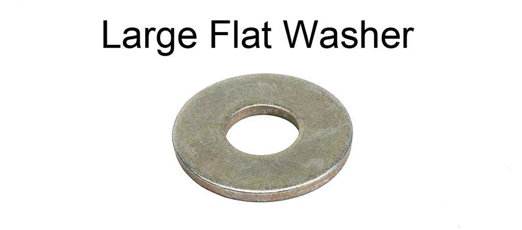
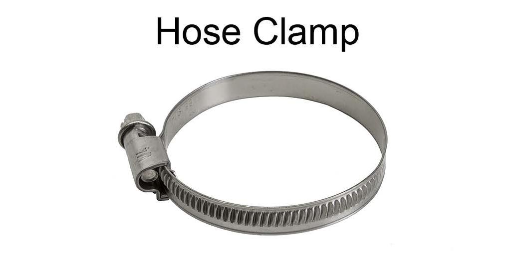
1 3430 Sacramento Dr., Unit D San Luis Obispo, CA Telephone: 805/ Fax: 805/ MM Tubular K-Member, (Mm5KM-7) This Kit Contains Congratulations on purchasing Maximum Motorsports Mustang K-Member. Read all instructions before beginning work. Following instructions in the proper sequence will ensure the best and easiest installation. Required Tools Standard assortment of hand tools Floor Jack & 4 jack stands 1/2 Torque Wrench Description QTY Alignment Pin 2 Aluminum Frame Rail Block, Driver 1 Aluminum Frame Rail Block, Passenger 1 Engine Mount Bracket, Stock-1 2 Engine Mount Bracket, Stock-2 2 Flange Nut, M Flange Nut, M Flange Bolt, M x 35mm 6 Hex Bolt, M x 25mm 16 Socket Head Cap Screw, M x 20mm 2 3/8 G8 Washer 16 Large Flat Washer 1 Hose Clamp 1 Zip Ties 2 Blue Loctite 1 MM K-member 1 Installation Instructions 1 Required Supplemental Items Mm5TR-2 Bumpsteer Kit MMT-11 Engine Support Brace or an engine hoist Mm5KM-9 Stock Crossmember Brace Adapter Kit (for vehicles that want to retain the OEM k-member to stock radiator core support brace) Installation Time Shop: 3.5 Hours Home Mechanic: 8 Hours Supplemental Installation Notes Alignment is required after installation Measuring and adjusting bumpsteer is recommended but not required Mm5KM-7r2.indd 1
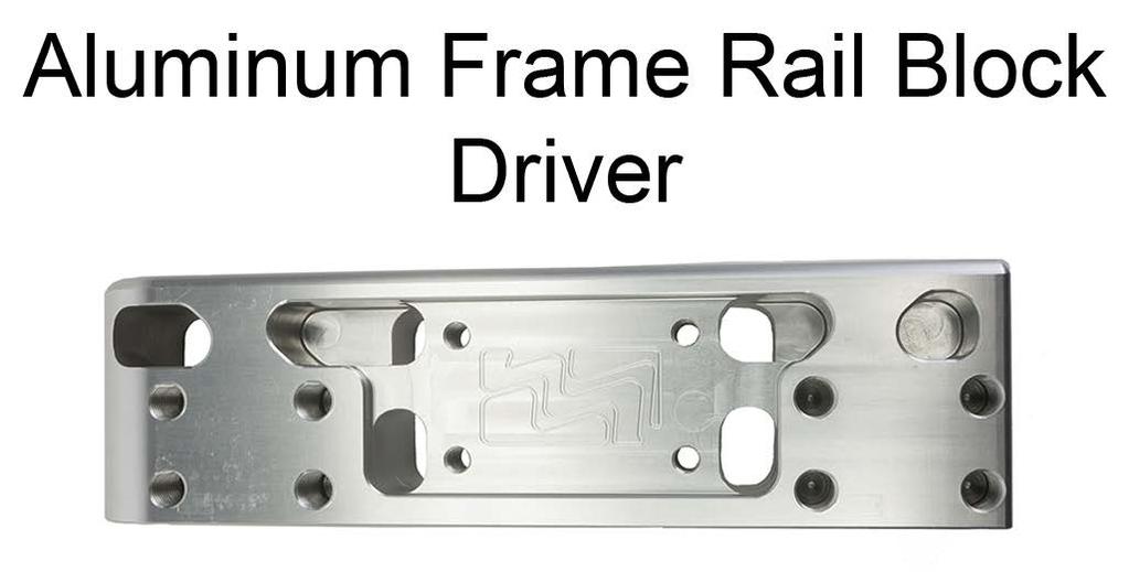
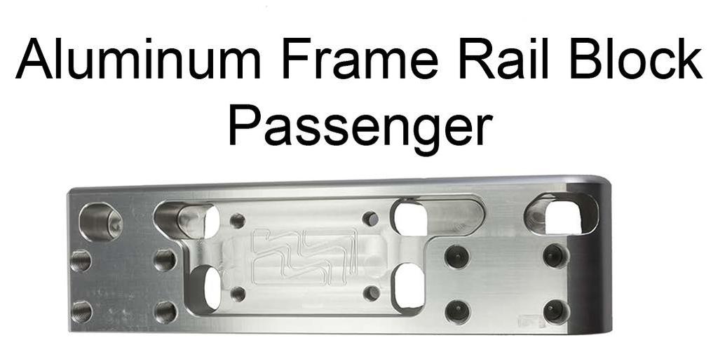
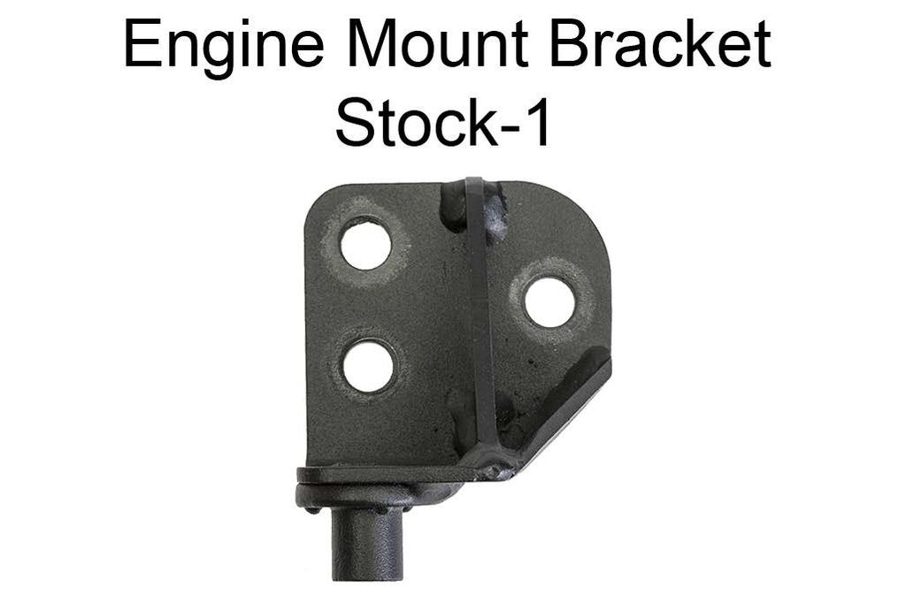
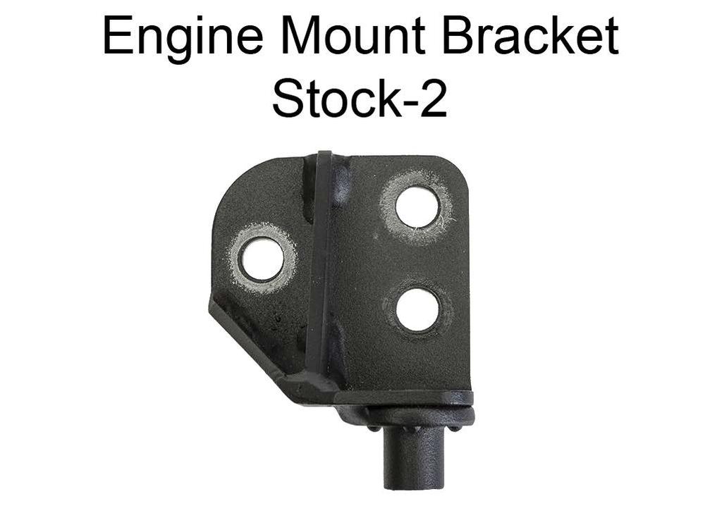
2 Component Identification 2 Mm5KM-7r2.indd


 Remove the 8 rear-most splitter screws using a 7mm nut driver.")

. 7.")
3 Installation 5. Support the engine securely from above. The MMT-11 Engine Support Beam can be used to support the engine. 1. Support the car level on 4 jack stands. Place the jack stands underneath the rocker panel pinch welds. WARNING: The engine must be properly supported from above before proceeding. Do NOT use a floor jack to hold the engine up from below, as it can move and allow the engine to fall. NOTE: The bottom of the rocker panel pinch welds should be at least 18 off the ground to allow easy removal of the k-member. 6. ( ONLY) Remove the 8 rear-most splitter screws using a 7mm nut driver. WARNING: Do NOT lift the car up from anywhere other than the rocker panel pinch welds, or damage will occur. 2. Remove the front wheels. 3. Disconnect the negative terminal of the battery. WARNING: Permanent damage to the electric steering rack control module can occur if it is removed while the battery is still connected. 4. Remove the two upper engine mount nuts using a deep 15mm socket (one on each side of car). 7. ( ONLY) Remove the 6 crossmember brace bolts and 2 nuts using a 15mm socket. Gently pull down the back edge of the splitter to gain access to the front mounting bolts. Mm5KM-7r2.indd 3


4 11. (Electric Rack ONLY) Disconnect both of the wiring harness plugs from the driver side of the steering rack. See the pictures below for proper removal. Each harness plug has two locking features to keep them connected to the steering rack. 8. Remove the outer steering tie-rod nuts from the spindle using a 18mm socket. (one on each spindle). 9. Remove the outer steering tie-rods from the spindle arms. If a bumpsteer kit is already installed, remove the rod-end from the tapered stud. 10. Remove the control arm ball joint pinch bolts using an 18mm socket and 15mm wrench. 4 Mm5KM-7r2.indd
 With the steering column unlocked, rotate the steering shaft so that the head of the bolt retaining the u-joint to the input shaft is accessible using a socket. 14.")
 Remove the bolt retaining the lower steering shaft u-joint to the steering rack input shaft using a 13mm socket. Stock K-member Removal 21.")
5 12. (Electric Rack ONLY) Disconnect the harness strain relief tab on the forward, outboard corner of the power steering rack control module. 13. (Electric Rack ONLY) With the steering column unlocked, rotate the steering shaft so that the head of the bolt retaining the u-joint to the input shaft is accessible using a socket. 14. (Electric Rack ONLY) Lock the steering column by removing the key from the ignition. WARNING: Do NOT rotate the steering wheel once the rack is removed. 15. (Electric Rack ONLY) Remove the bolt retaining the lower steering shaft u-joint to the steering rack input shaft using a 13mm socket. Stock K-member Removal 21. Remove the four (4) k-member lower frame rail mounting pad bolts using an 18mm socket. NOTE: These bolts require a lot of effort to remove due to the thread retaining compound used. 16. (Electric Rack ONLY) Proceed to the Stock K-member Removal section. 17. (Hydraulic Rack ONLY) Remove the bolt that holds the power steering hose to the center of the k-member. 22. Loosen, but not remove the four (4) k-member upper frame rail mounting nuts using an 18mm socket. 18. (Hydraulic Rack ONLY) With the steering column unlocked, rotate the steering shaft so that the head of the bolt retaining the u-joint to the input shaft is accessible using a socket. 19. (Hydraulic Rack ONLY) Lock the steering column by removing the key from the ignition. WARNING: Do NOT rotate the steering wheel once the rack is removed. 20. (Hydraulic Rack ONLY) Remove the bolt retaining the lower steering shaft u-joint to the steering rack input shaft using a 13mm socket. Mm5KM-7r2.indd 5

 Lower the k-member, while being careful to not over-stress the attached hydraulic lines, just far enough that the two rack mounting bolts can be accessed.")
6 23. Support the k-member with a floor jack and remove the nuts loosened in Step (Electric Rack ONLY) Gently lower the k-member to the ground. The spindles may need to be jiggled slightly to remove the control arm ball joints as the k-member is lowered. Stock K-member Disassembly 29. (Electric Rack ONLY) Remove the 3 bolts retaining the steering rack to the stock k-member. Retain the bolts as they will be reused. 25. (Hydraulic Rack ONLY) Lower the k-member, while being careful to not over-stress the attached hydraulic lines, just far enough that the two rack mounting bolts can be accessed. The spindles may need to be jiggled slightly to remove the control arm ball joints as the k-member is lowered. 26. (Hydraulic Rack ONLY) Remove the two rack mounting bolts using an 18mm socket. Retain the bolts as they will be reused. NOTE: The rack mounting bolts will be VERY difficult to remove due to thread retaining compound used. 27. Strap the steering rack to the front swaybar using the provided zip-ties. 30. Remove the 4 bolts holding the engine mounts to the stock k-member using a 13mm socket. Retain the bolts, they will be reused. 28. Safely lower the k-member to the ground. 31. Remove both front control arms from the stock k-member. Use an 18mm socket for the front bolts and a 21mm socket for the two rear nuts. 32. If heat shields are present on the rearward bushing shells of the stock control arms, remove them now. They will not be reused. 6 Mm5KM-7r2.indd


7 Aluminum Frame Rail Block Preparation 33. Insert one of the provided 8mm socket head caps screws into each of the provided alignment pins and thread them into the tops of the aluminum frame rail blocks. Tighten them to 20 Nm (16 lb-ft). 36. Take 12 of the provided 10mm x 25mm long bolts, with a washer under each head, and apply a drop of Blue Loctite to the first few threads of each bolt. Loosely thread them into the mounting holes for the engine mount adapter plates, but do not tighten. NOTE: The mounting holes are slightly oversized to allow for production tolerances. Torquing the bolts before installing the engine isolators may cause the mounting holes to be misaligned. 34. Lay the two aluminum frame rail blocks adjacent to each other so that the 6 threaded holes are facing you. The alignment pins should be facing up. 35. Locate the 4 engine mount brackets and place them on the aluminum frame rail blocks as shown. The welded on nuts should be oriented downwards. 37. Install the engine isolators onto the aluminum frame rail block assemblies. Loosely thread the factory mounting bolts down, but do not torque. 38. Torque the 10mm bolts installed in Step 36 to 41 Nm (30 lb-ft) and torque the factory engine isolator bolts installed in Step 37 to 55 Nm (41 lb-ft). Mm5KM-7r2.indd 7

. 41.")

8 MM K-member Preparation 39. Bolt the 2-point k-member brace to the k-member using 4 of the provided 10mm x 25mm long bolts with a washer under the head of each bolt. The bottom of the brace should be flush with the bottom of the k-member. NOTE: If installing the optional Mm5KB2-21 k-member brace with transmission cooling scoop, do so at this time. 43. Reuse the 4 factory nuts removed in Step 23 and loosely thread them onto the 4 upper frame rail mounting bolts so that the aluminum frame rail blocks can still be moved with slight effort. 44. Install the lower frame rail mounting bolts that were removed in Step 21 into the rear mounting pads of the k-member, but do not tighten. 40. Torque the k-member brace bolts to 48 Nm (35 lb-ft). 41. Apply the provided Blue Loctite to the threads of the 6 provided 12mm x 35mm long flange bolts and loosely bolt the aluminum frame rail blocks to the MM K-member so that they can slightly slide around. The corner of the blocks with the large radius faces forwards and outwards. 45. Slide the k-member assembly forward as far as it will go. 46. Set the k-member side-to-side position by aligning the two counter bored holes on the driver side aluminum frame rail mounting block with the edge of the k-member s upper frame rail mounting flange. 47. Torque the upper frame rail mounting nuts to 115 Nm (85 lb-ft). MM K-member Installation 42. Using a floor jack or helper, lift the k-member into position so that the 4 bolts protruding from the upper frame rails slide into the aluminum frame rail blocks. Once near the frame rail, the aluminum frame rail blocks must be moved backand-forth slightly to help position the alignment pins into the locating hole and slot on the frame rails. NOTE: Slide the driver side up into position first, then the passenger side. NOTE: Be sure that the studs on the engine isolators have passed through their mounting holes on the engine. 48. Torque the lower frame rail mounting bolts to 115 Nm (85 lb-ft). 49. Torque the 6 flange bolts installed in Step 41 to 82 Nm (60 lb-ft). 8 Mm5KM-7r2.indd

9 50. Install the lower control arms into position on the k-member, using the lower set of mounting holes. Reuse the factory hardware to attach the rear pivot bushings to the k-member. 51. Install the lower control arm forward pivot mounting bolts, removed in Step 31, into the lowest control arm mounting holes of the k-member, along with one of the provided 14mm flanged nuts. 61. Reinstall the spindle ball joint bolts/nuts and torque to 103 Nm (73 lb-ft). 62. (Hydraulic Rack ONLY) Use the provided hose clamp to secure the power steering hose relief bracket to the steering rack. Slip the hose clamp through the mounting slot of the bracket, then around the steering rack housing, and firmly tighten. NOTE: Dot not tighten the forward pivot bolts yet. 52. Torque the rear pivot bushing mounting hardware to 185 Nm (136 lb-ft). NOTE: The rear pivot bushing must be torqued first to remove any preload in the rubber bushings. 53. Torque the front pivot bushing mounting hardware to 205 Nm (151 lb-ft). 54. Reinstall the steering rack, making sure to slide the steering shaft u-joint onto the input shaft of the rack. 55. Install the two factory 12mm rack mounting bolts into the steering rack housing and through the mounting bosses on the k-member (removed in Step 26 for hydraulic racks & Step 29 for electric racks). NOTE: These are fine threaded bolts. 56. Use the two provided 12mm-1.5 flange nuts to secure the steering rack mounting bolts. Torque the nuts to 115 Nm (85 lb-ft). 57. (Electric Rack ONLY) Place the provided large flat washer onto the 14mm steering rack mounting bolt and insert from the top of the rack. Use the remaining provided 14mm flanged nut and torque to 115 Nm (85 lb-ft). 58. Reinstall the steering shaft u-joint pinch bolt and torque to 25 Nm (18 lb-ft). 59. (Electric Rack ONLY) Reconnect the two wiring harness plugs and strain relief tab removed in Steps 11 to Insert the control arm ball joints into the spindles. It may be necessary to loosen/remove spindle-to-strut mounting bolts if the control arm cannot be pushed down far enough to engage the ball joint. Mm5KM-7r2.indd Install an Mm5TR-2 Bumpsteer Kit. Place the following spacers between the top of the rod end and the bottom of the stud s shoulder: 0.03, 0.24, and The remaining spacers must be placed below the rod end. 64. ( ONLY) If the stock crossmember brace removed in Steps 6 to 7 is being reused, a Mm5KM-9 Crossmember Brace Adapter Bracket kit should be installed at this time. 65. ( ONLY) Install the 8 rear-most splitter screws removed in Step Lower the engine onto the engine isolators and remove the MMT-11 Engine Support Brace. 67. Reinstall the two upper engine isolator nuts and torque to 63 Nm (46 lb-ft)
10 68. Reinstall the front wheels and safely lower the vehicle to the ground. 69. Torque to wheels to the factory specifications. 70. Reconnect the battery terminal. 71. Have the vehicle properly aligned. 72. Test drive and enjoy! 10 Mm5KM-7r2.indd
MM Caster Camber Plates, (Mm6CC-10)
") 3430 Sacramento Dr., Unit D San Luis Obispo, CA 93401 Telephone: 805/544-8748 Fax: 805/544-8645 www.maximummotorsports.com MM Caster Camber Plates, 2015+ (Mm6CC-10) Read all instructions before beginning
3430 Sacramento Dr., Unit D San Luis Obispo, CA 93401 Telephone: 805/544-8748 Fax: 805/544-8645 www.maximummotorsports.com MM Caster Camber Plates, 2015+ (Mm6CC-10) Read all instructions before beginning
MM Caster/Camber Plates, (MMCC7989)
") 3430 Sacramento Dr., Unit D San Luis Obispo, CA 93401 Telephone: 805/544-8748 Fax: 805/544-8645 www.maximummotorsports.com MM Caster/Camber Plates, 1979-89 (MMCC7989) IMPORTANT: The bearing used in our
3430 Sacramento Dr., Unit D San Luis Obispo, CA 93401 Telephone: 805/544-8748 Fax: 805/544-8645 www.maximummotorsports.com MM Caster/Camber Plates, 1979-89 (MMCC7989) IMPORTANT: The bearing used in our
Adjustable Tie-rod Ends (Mm5TR-1)
") 3430 Sacramento Dr., Unit D San Luis Obispo, CA 93401 Telephone: 805/544-8748 Fax: 805/544-8645 www.maximummotorsports.com 2005-10 Adjustable Tie-rod Ends (Mm5TR-1) 3. Remove the front wheels. 4. Loosen
3430 Sacramento Dr., Unit D San Luis Obispo, CA 93401 Telephone: 805/544-8748 Fax: 805/544-8645 www.maximummotorsports.com 2005-10 Adjustable Tie-rod Ends (Mm5TR-1) 3. Remove the front wheels. 4. Loosen
2011+ Adjustable Tie-rod Ends (Mm5TR-2)
") 3430 Sacramento Dr., Unit D San Luis Obispo, CA 93401 Telephone: 805/544-8748 Fax: 805/544-8645 www.maximummotorsports.com 2011+ Adjustable Tie-rod Ends (Mm5TR-2) Instructions 1. Set the parking brake
3430 Sacramento Dr., Unit D San Luis Obispo, CA 93401 Telephone: 805/544-8748 Fax: 805/544-8645 www.maximummotorsports.com 2011+ Adjustable Tie-rod Ends (Mm5TR-2) Instructions 1. Set the parking brake
Cobra IRS Aluminum Differential Bushings (MMIRSB-40.2)
") 3430 Sacramento Dr., Unit D San Luis Obispo, CA 93401 Telephone: 805/544-8748 Fax: 805/544-8645 www.maximummotorsports.com Cobra IRS Aluminum Differential Bushings (MMIRSB-40.2) The MM front differential
3430 Sacramento Dr., Unit D San Luis Obispo, CA 93401 Telephone: 805/544-8748 Fax: 805/544-8645 www.maximummotorsports.com Cobra IRS Aluminum Differential Bushings (MMIRSB-40.2) The MM front differential
MM Caster/Camber Plates, (Mm5CC-7)
") 3430 Sacramento Dr., Unit D San Luis Obispo, CA 93401 Telephone: 805/544-8748 Fax: 805/544-8645 www.maximummotorsports.com MM Caster/Camber Plates, 2005-14 (Mm5CC-7) Supplemental Installation Notes This
3430 Sacramento Dr., Unit D San Luis Obispo, CA 93401 Telephone: 805/544-8748 Fax: 805/544-8645 www.maximummotorsports.com MM Caster/Camber Plates, 2005-14 (Mm5CC-7) Supplemental Installation Notes This
Coil-Over Kit, MMD-RC1xxxx Shock (MMCO-22)
") 3430 Sacramento Dr., Unit D San Luis Obispo, CA 93401 Telephone: 805/544-8748 Fax: 805/544-8645 www.maximummotorsports.com Coil-Over Kit, MMD-RC1xxxx Shock (MMCO-22) Supplemental Installation Notes This
3430 Sacramento Dr., Unit D San Luis Obispo, CA 93401 Telephone: 805/544-8748 Fax: 805/544-8645 www.maximummotorsports.com Coil-Over Kit, MMD-RC1xxxx Shock (MMCO-22) Supplemental Installation Notes This
Coil-Over Kit, MMD-RC1xxxx Shock (MMCO-23)
") 3430 Sacramento Dr., Unit D San Luis Obispo, CA 93401 Telephone: 805/544-8748 Fax: 805/544-8645 www.maximummotorsports.com Coil-Over Kit, MMD-RC1xxxx Shock (MMCO-23) Supplemental Installation Notes This
3430 Sacramento Dr., Unit D San Luis Obispo, CA 93401 Telephone: 805/544-8748 Fax: 805/544-8645 www.maximummotorsports.com Coil-Over Kit, MMD-RC1xxxx Shock (MMCO-23) Supplemental Installation Notes This
IRS Racing Brake Kit (MMBAK-15, -16)
") 3430 Sacramento Dr., Unit D San Luis Obispo, CA 93401 Telephone: 805/544-8748 Fax: 805/544-8645 www.maximummotorsports.com IRS Racing Brake Kit (MMBAK-15, -16) Floating rotors (MMBAK-16 ONLY) can move
3430 Sacramento Dr., Unit D San Luis Obispo, CA 93401 Telephone: 805/544-8748 Fax: 805/544-8645 www.maximummotorsports.com IRS Racing Brake Kit (MMBAK-15, -16) Floating rotors (MMBAK-16 ONLY) can move
3430 Sacramento Dr., Unit D San Luis Obispo, CA Telephone: 805/ Fax: 805/
 3430 Sacramento Dr., Unit D San Luis Obispo, CA 93401 Telephone: 805/544-8748 Fax: 805/544-8645 www.maximummotorsports.com MM Caster/Camber Plates, 2005-10 (Mm5CC-1) Read all instructions before beginning
4.6L Oil Filter Relocation Kit, (OC-7)
") 3430 Sacramento Dr., Unit D San Luis Obispo, CA 93401 Telephone: 805/544-8748 Fax: 805/544-8645 www.maximummotorsports.com 4.6L Oil Filter Relocation Kit, 2003-04 (OC-7) Filter Mount Installation 4. Remove
3430 Sacramento Dr., Unit D San Luis Obispo, CA 93401 Telephone: 805/544-8748 Fax: 805/544-8645 www.maximummotorsports.com 4.6L Oil Filter Relocation Kit, 2003-04 (OC-7) Filter Mount Installation 4. Remove
Hybrid Steering Shaft, SN95 Rack in Fox Chassis (MMST-13)
") 3430 Sacramento Dr., Unit D San Luis Obispo, CA 93401 Telephone: 805/544-8748 Fax: 805/544-8645 www.maximummotorsports.com Hybrid Steering Shaft, SN95 Rack in Fox Chassis (MMST-13) Improving Performance
3430 Sacramento Dr., Unit D San Luis Obispo, CA 93401 Telephone: 805/544-8748 Fax: 805/544-8645 www.maximummotorsports.com Hybrid Steering Shaft, SN95 Rack in Fox Chassis (MMST-13) Improving Performance
MM Brake Hose Kit (MMBK13R)
") 3430 Sacramento Dr., Unit D San Luis Obispo, CA 93401 Telephone: 805/544-8748 Fax: 805/544-8645 www.maximummotorsports.com MM Brake Hose Kit (MMBK13R) Read all instructions before beginning work. Following
3430 Sacramento Dr., Unit D San Luis Obispo, CA 93401 Telephone: 805/544-8748 Fax: 805/544-8645 www.maximummotorsports.com MM Brake Hose Kit (MMBK13R) Read all instructions before beginning work. Following
MM K-Member, chassis with 5.0L engine (MMKM-1.1)
") 3430 Sacramento Dr., Unit D San Luis Obispo, CA 93401 Telephone: 805/544-8748 Fax: 805/544-8645 www.maximummotorsports.com Read all instructions before beginning work. Following instructions in the proper
3430 Sacramento Dr., Unit D San Luis Obispo, CA 93401 Telephone: 805/544-8748 Fax: 805/544-8645 www.maximummotorsports.com Read all instructions before beginning work. Following instructions in the proper
2. Remove front wheels.
 Read all instructions before beginning work. Following instructions in the proper sequence will ensure the best and easiest installation. Thank you for purchasing Maximum Motorsports Caster/Camber Plates.
MM Brake Line Kit (MMBK14R)
") 3430 Sacramento Dr., Unit D San Luis Obispo, CA 93401 Telephone: 805/544-8748 Fax: 805/544-8645 www.maximummotorsports.com MM Brake Line Kit (MMBK14R) Read all instructions before beginning work. Following
3430 Sacramento Dr., Unit D San Luis Obispo, CA 93401 Telephone: 805/544-8748 Fax: 805/544-8645 www.maximummotorsports.com MM Brake Line Kit (MMBK14R) Read all instructions before beginning work. Following
Coil-Over Kit, MMD-RC0xxxx Shock (MMCO-20)
") 3430 Sacramento Dr., Unit D San Luis Obispo, CA 93401 Telephone: 805/544-8748 Fax: 805/544-8645 www.maximummotorsports.com Coil-Over Kit, MMD-RC0xxxx Shock (MMCO-20) Supplemental Installation Notes OEM
3430 Sacramento Dr., Unit D San Luis Obispo, CA 93401 Telephone: 805/544-8748 Fax: 805/544-8645 www.maximummotorsports.com Coil-Over Kit, MMD-RC0xxxx Shock (MMCO-20) Supplemental Installation Notes OEM
MM Rear Coil-Over Kit - Koni Single and Double Adjustable Shocks (MMCO-5)
") 3430 Sacramento Dr., Unit D San Luis Obispo, CA 93401 Telephone: 805/544-8748 Fax: 805/544-8645 www.maximummotorsports.com MM Rear Coil-Over Kit - Koni Single and Double Adjustable Shocks (MMCO-5) Read
3430 Sacramento Dr., Unit D San Luis Obispo, CA 93401 Telephone: 805/544-8748 Fax: 805/544-8645 www.maximummotorsports.com MM Rear Coil-Over Kit - Koni Single and Double Adjustable Shocks (MMCO-5) Read
2005+ Roll Bar (Mm5RB-20.1 to -20.6) Recommended Center punch 1/8" pilot drill 1-3/4" Hole saw 2" Hole saw
 Recommended Center punch 1/8 pilot drill 1-3/4 Hole saw 2 Hole saw") 3430 Sacramento Dr., Unit D San Luis Obispo, CA 93401 Telephone: 805/544-8748 Fax: 805/544-8645 www.maximummotorsports.com 2005+ Roll Bar (Mm5RB-20.1 to -20.6) Recommended Center punch 1/8" pilot drill
3430 Sacramento Dr., Unit D San Luis Obispo, CA 93401 Telephone: 805/544-8748 Fax: 805/544-8645 www.maximummotorsports.com 2005+ Roll Bar (Mm5RB-20.1 to -20.6) Recommended Center punch 1/8" pilot drill
MM Rear Coil-Over Kit - Bilstein Shocks (MMCO-3)
") 3430 Sacramento Dr., Unit D San Luis Obispo, CA 93401 Telephone: 805/544-8748 Fax: 805/544-8645 www.maximummotorsports.com MM Rear Coil-Over Kit - Bilstein Shocks (MMCO-3) Read all instructions before
3430 Sacramento Dr., Unit D San Luis Obispo, CA 93401 Telephone: 805/544-8748 Fax: 805/544-8645 www.maximummotorsports.com MM Rear Coil-Over Kit - Bilstein Shocks (MMCO-3) Read all instructions before
Standard Duty Oil Filter Relocation Kit (OC-8)
") 3430 Sacramento Dr., Unit D San Luis Obispo, CA 93401 Telephone: 805/544-8748 Fax: 805/544-8645 www.maximummotorsports.com Standard Duty Oil Filter Relocation Kit (OC-8) Filter Mount Installation 4. Remove
3430 Sacramento Dr., Unit D San Luis Obispo, CA 93401 Telephone: 805/544-8748 Fax: 805/544-8645 www.maximummotorsports.com Standard Duty Oil Filter Relocation Kit (OC-8) Filter Mount Installation 4. Remove
Severe Duty Oil Filter Relocation Kit (OC-9)
") 3430 Sacramento Dr., Unit D San Luis Obispo, CA 93401 Telephone: 805/544-8748 Fax: 805/544-8645 www.maximummotorsports.com Severe Duty Oil Filter Relocation Kit (OC-9) Filter Mount Installation 4. Remove
3430 Sacramento Dr., Unit D San Luis Obispo, CA 93401 Telephone: 805/544-8748 Fax: 805/544-8645 www.maximummotorsports.com Severe Duty Oil Filter Relocation Kit (OC-9) Filter Mount Installation 4. Remove
MM K-Member, chassis with 4.6 engine (MMKM-2.1)
") 3430 Sacramento Dr., Unit D San Luis Obispo, CA 93401 Telephone: 805/544-8748 Fax: 805/544-8645 www.maximummotorsports.com MM K-Member, 1979-95 chassis with 4.6 engine (MMKM-2.1) most rigid, and yet our
3430 Sacramento Dr., Unit D San Luis Obispo, CA 93401 Telephone: 805/544-8748 Fax: 805/544-8645 www.maximummotorsports.com MM K-Member, 1979-95 chassis with 4.6 engine (MMKM-2.1) most rigid, and yet our
Front Coil-Over Kit, MMD-FCxxxxx Series (MMCO-24)
") 3430 Sacramento Dr., Unit D San Luis Obispo, CA 93401 Telephone: 805/544-8748 Fax: 805/544-8645 www.maximummotorsports.com Front Coil-Over Kit, MMD-FCxxxxx Series (MMCO-24) Overlooked by other companies,
3430 Sacramento Dr., Unit D San Luis Obispo, CA 93401 Telephone: 805/544-8748 Fax: 805/544-8645 www.maximummotorsports.com Front Coil-Over Kit, MMD-FCxxxxx Series (MMCO-24) Overlooked by other companies,
Manual Brake Conversion Kit, (MMBAK-13)
") 3430 Sacramento Dr., Unit D San Luis Obispo, CA 93401 Telephone: 805/544-8748 Fax: 805/544-8645 www.maximummotorsports.com Manual Brake Conversion Kit, 1994-95 (MMBAK-13) The MM kit includes a CNC machined
3430 Sacramento Dr., Unit D San Luis Obispo, CA 93401 Telephone: 805/544-8748 Fax: 805/544-8645 www.maximummotorsports.com Manual Brake Conversion Kit, 1994-95 (MMBAK-13) The MM kit includes a CNC machined
MM Brake Line Kit for Fox-IRS Swap (MMBAK-21)
") 3430 Sacramento Dr., Unit D San Luis Obispo, CA 93401 Telephone: 805/544-8748 Fax: 805/544-8645 www.maximummotorsports.com MM Brake Line Kit for Fox-IRS Swap (MMBAK-21) Supplemental Installation Notes
3430 Sacramento Dr., Unit D San Luis Obispo, CA 93401 Telephone: 805/544-8748 Fax: 805/544-8645 www.maximummotorsports.com MM Brake Line Kit for Fox-IRS Swap (MMBAK-21) Supplemental Installation Notes
US Patent You will find many features that set our Caster/Camber Plates apart from the rest.
 3430 Sacramento Dr., Unit D San Luis Obispo, CA 93401 Telephone: 805/544-8748 Fax: 805/544-8645 www.maximummotorsports.com US Patent 6485223 Read all instructions before beginning work. Following instructions
2010 Current Ford Raptor Lower Control Arm Installation Instructions
 PREPARATION 2010 Current Ford Raptor Lower Control Arm Installation Instructions 1. Disconnect the negative terminal on the battery. Park the vehicle on level ground and set the emergency brake. 2. We
MM Adjustable IRS Tie-Rod (MMIRSTR-2)
") 3430 Sacramento Dr., Unit D San Luis Obispo, CA 93401 Telephone: 805/544-8748 Fax: 805/544-8645 www.maximummotorsports.com MM Adjustable IRS Tie-Rod (MMIRSTR-2) Sample Bumpsteer Curve: Read all instructions
3430 Sacramento Dr., Unit D San Luis Obispo, CA 93401 Telephone: 805/544-8748 Fax: 805/544-8645 www.maximummotorsports.com MM Adjustable IRS Tie-Rod (MMIRSTR-2) Sample Bumpsteer Curve: Read all instructions
SPECIAL TOOLS REQUIRED:
 INSTALLATION INSTRUCTIONS FOR 2010-15 TOYOTA 4RUNNER WITH XREAS SUSPENSION 3 SUSPENSION LIFT KIT PART NUMBER 432X WARNING!!! READ AND UNDERSTAND ALL INSTRUCTIONS BEFORE PROCEEDING. MAKE SURE THAT YOU HAVE
MM IRS Coil-Over Kit - Bilstein/MM Shocks (MMCO-4)
") 3430 Sacramento Dr., Unit D San Luis Obispo, CA 93401 Telephone: 805/544-8748 Fax: 805/544-8645 www.maximummotorsports.com MM IRS Coil-Over Kit - Bilstein/MM Shocks (MMCO-4) The lower spring perch is drilled
3430 Sacramento Dr., Unit D San Luis Obispo, CA 93401 Telephone: 805/544-8748 Fax: 805/544-8645 www.maximummotorsports.com MM IRS Coil-Over Kit - Bilstein/MM Shocks (MMCO-4) The lower spring perch is drilled
»Product» Safety Warning
 C1351 Installation Instructions 2014 Chevy/GMC, ½ Ton, 2/4wd 3.5" Combo Kit Read and understand all instructions and warnings prior to installation of product and operation of vehicle. Zone Offroad Products
2005+ Drag Race Roll Bar (Mm5RB-20)
") 3430 Sacramento Dr., Unit D San Luis Obispo, CA 93401 Telephone: 805/544-8748 Fax: 805/544-8645 www.maximummotorsports.com 2005+ Drag Race Roll Bar (Mm5RB-20) Note that the NHRA DOES allow the door bars
3430 Sacramento Dr., Unit D San Luis Obispo, CA 93401 Telephone: 805/544-8748 Fax: 805/544-8645 www.maximummotorsports.com 2005+ Drag Race Roll Bar (Mm5RB-20) Note that the NHRA DOES allow the door bars
Drag Race Roll Bar (MMRB-6, -7)
") 3430 Sacramento Dr., Unit D San Luis Obispo, CA 93401 Telephone: 805/544-8748 Fax: 805/544-8645 www.maximummotorsports.com 1994-04 Drag Race Roll Bar (MMRB-6, -7) The Maximum Motorsports 6-point Drag Race
3430 Sacramento Dr., Unit D San Luis Obispo, CA 93401 Telephone: 805/544-8748 Fax: 805/544-8645 www.maximummotorsports.com 1994-04 Drag Race Roll Bar (MMRB-6, -7) The Maximum Motorsports 6-point Drag Race
Team Z Motorsports. K-Member installation instructions
 Team Z Motorsports K-Member installation instructions Parts Included: 1-Tubular K-Member Needed Items-Solid Steering Shaft Offset Steering Rack Bushings Optional-Heavy Duty Bolt Kit Tubular Front Lower
Roll Bar (MMRB-1.1 to 1.7)
") 3430 Sacramento Dr., Unit D San Luis Obispo, CA 93401 Telephone: 805/544-8748 Fax: 805/544-8645 www.maximummotorsports.com 1979-93 Roll Bar (MMRB-1.1 to 1.7) The Maximum Motorsports RB-1.1 to -1.7 Roll
3430 Sacramento Dr., Unit D San Luis Obispo, CA 93401 Telephone: 805/544-8748 Fax: 805/544-8645 www.maximummotorsports.com 1979-93 Roll Bar (MMRB-1.1 to 1.7) The Maximum Motorsports RB-1.1 to -1.7 Roll
INSTALLATION INSTRUCTIONS 97 FORD EXPEDITION
 INSTALLATION INSTRUCTIONS 97 FORD EXPEDITION 1. Read the instructions completely and carefully before you begin. Check the kit for proper contents (refer to the part s list and the picture diagrams). Before
MM Panhard Bar, Mustang (MMPBA)
") 3430 Sacramento Dr., Unit D San Luis Obispo, CA 93401 Telephone: 805/544-8748 Fax: 805/544-8645 www.maximummotorsports.com MM Panhard Bar, 1979-98 Mustang (MMPBA) Important Note for Customers with Baer
3430 Sacramento Dr., Unit D San Luis Obispo, CA 93401 Telephone: 805/544-8748 Fax: 805/544-8645 www.maximummotorsports.com MM Panhard Bar, 1979-98 Mustang (MMPBA) Important Note for Customers with Baer
Standard Duty Oil Filter Relocation Kit (OC-3)
") 3430 Sacramento Dr., Unit D San Luis Obispo, CA 93401 Telephone: 805/544-8748 Fax: 805/544-8645 www.maximummotorsports.com Standard Duty Oil Filter Relocation Kit (OC-3) Read all of the instructions before
3430 Sacramento Dr., Unit D San Luis Obispo, CA 93401 Telephone: 805/544-8748 Fax: 805/544-8645 www.maximummotorsports.com Standard Duty Oil Filter Relocation Kit (OC-3) Read all of the instructions before
1501 Industrial Way N., Toms River, NJ Fax: PACKING LIST MUSTANG LONG TUBE HEADERS (M30000)
") 2/18/04 1501 Industrial Way N., Toms River, NJ 08755 732-349-2109 Fax:732-244-0867 ADVANCED - Installation requires professional-type tools and advanced automotive-service skills. If you lack experience
2/18/04 1501 Industrial Way N., Toms River, NJ 08755 732-349-2109 Fax:732-244-0867 ADVANCED - Installation requires professional-type tools and advanced automotive-service skills. If you lack experience
MM K-Member, chassis w/4.6l engine & Hellion Turbo Kit (MMKM-3.1)
") 3430 Sacramento Dr., Unit D San Luis Obispo, CA 93401 Telephone: 805/544-8748 Fax: 805/544-8645 www.maximummotorsports.com MM K-Member, 1979-95 chassis w/4.6l engine & Hellion Turbo Kit (MMKM-3.1) Proper
3430 Sacramento Dr., Unit D San Luis Obispo, CA 93401 Telephone: 805/544-8748 Fax: 805/544-8645 www.maximummotorsports.com MM K-Member, 1979-95 chassis w/4.6l engine & Hellion Turbo Kit (MMKM-3.1) Proper
Convertible MM Roll Bar (MMRB-10.1 to -10.7)
") 3430 Sacramento Dr., Unit D San Luis Obispo, CA 93401 Telephone: 805/544-8748 Fax: 805/544-8645 www.maximummotorsports.com 1983-93 Convertible MM Roll Bar (MMRB-10.1 to -10.7) The Maximum Motorsports RB-10.1
3430 Sacramento Dr., Unit D San Luis Obispo, CA 93401 Telephone: 805/544-8748 Fax: 805/544-8645 www.maximummotorsports.com 1983-93 Convertible MM Roll Bar (MMRB-10.1 to -10.7) The Maximum Motorsports RB-10.1
AEV30308AA Last Updated: 05/31/18. 4 DUALSPORT sc SUSPENSION system for RAM 1500 air ride standard and rebel INSTALLATION GUIDE
 AEV30308AA Last Updated: 05/31/18 4 DUALSPORT sc SUSPENSION system for RAM 1500 air ride standard and rebel INSTALLATION GUIDE PLEASE READ BEFORE YOU START TO GUARANTEE A QUALITY INSTALLATION, WE RECOMMEND
63162K 2015 Chevrolet Colorado 4WD Leveling Kit w/ 1 Rear Lift Kit
 PRO COMP SUSPENSION 63162K 2015 Chevrolet Colorado 4WD Leveling Kit w/ 1 Rear Lift Kit This document contains very important information that includes warranty information and instructions for resolving
Installation Instructions
 Installation Instructions 6 Suspension System FTS25005BK / FTS25006BK 2006-2012 Nissan Frontier 2wd/4wd SHORT BED ONLY Tool List: (not included) Floor Jack & Jack Stands Assorted Metric & S.A.E Sockets
»Product» Safety Warning
 #J9210 Installation Instructions 2007-13 Jeep Wrangler JK 2" Body Lift Kit Read and understand all instructions and warnings prior to installation of product and operation of vehicle. Zone Offroad Products
1501 Industrial Way N., Toms River, NJ Fax: PACKING LIST MUSTANG GT LONG TUBE HEADERS (M30000)
") ADVANCED - Installation requires professional-type tools and advanced automotive-service skills. If you lack experience with internal engine modifications, an Advanced installation is probably beyond your
ADVANCED - Installation requires professional-type tools and advanced automotive-service skills. If you lack experience with internal engine modifications, an Advanced installation is probably beyond your
1 M-3000-H4 F150 4X4 Lowering Kit
 READ INSTRUCTIONS COMPLETELY THROUGH BEFORE STARTING. IT IS RECOMMENDED THAT INSTALLATION BE DONE BY A QUALIFIED MECHANIC. REPLACE ALL STOCK PARTS THAT ARE DAMAGED OR WORN. ALWAYS WEAR EYE PROTECTION.
Ford F150/Raptor & F150 Lower Control Arm Installation Instructions
 2009-2010 Ford F150/Raptor & 2015-2017 F150 Lower Control Arm Installation Instructions PREPARATION 1. Disconnect the negative terminal on the battery. Park the vehicle on level ground and set the emergency
B5 A4 1.8t Front Mount Intercooler Install Instructions
 B5 A4 1.8t Front Mount Intercooler Install Instructions Only work underneath your vehicle after properly supporting it with adequate jack stands on a flat surface. NEVER work under a vehicle only supported
MM Heavy Duty Torque-arm (MMTA-3 & -4) Engine Torque Table 4.56: : :
 Engine Torque Table 4.56: : :") 3430 Sacramento Dr., Unit D San Luis Obispo, CA 93401 Telephone: 805/544-8748 Orders Only: 800/839-0928 Fax: 805/544-8645 The ultimate rear suspension for your Mustang is now available from Maximum Motorsports.
3430 Sacramento Dr., Unit D San Luis Obispo, CA 93401 Telephone: 805/544-8748 Orders Only: 800/839-0928 Fax: 805/544-8645 The ultimate rear suspension for your Mustang is now available from Maximum Motorsports.
'99-03 CHEVROLET/GMC IFS 4WD 6" SUSPENSION SYSTEM P/N INSTALLATION INSTRUCTIONS
 1/16/04 '99-03 CHEVROLET/GMC IFS 4WD 6" SUSPENSION SYSTEM P/N. 10-41099 INSTALLATION INSTRUCTIONS NOTE: Each Lift Kit and options to Lift Kits are packaged separately. Therefore, installation procedures
2005-Pres. Ford Mustang Camber Plate Installation Instructions:
 2005-Pres. Ford Mustang Camber Plate Installation Instructions: J&M Products once again outdoes our competitors with these fully adjustable PATENT PENDING Camber & Caster plate assemblies for the 2005-2010
INSTALLATION INSTRUCTIONS
 INSTALLATION INSTRUCTIONS --1075 North Ave. Sanger, CA 93657-3539 local: 559-875-0222 fax: 559-876-2259 toll free: 800-445-3767-- 2505 Lowering Spindle Assembly Installation Instructions ½ TON SILVERADO
Installation Instructions. 6 Basic System FTS21060BK / FTS21061BK / FTS21042BK GM 2WD C1500 P/U ONLY
 Installation Instructions 6 Basic System FTS21060BK / FTS21061BK / FTS21042BK 2007-13 GM 2WD C1500 P/U ONLY 2007-13 GM 1500 Truck Basic System FTS21060BK / FTS21061BK / FTS21042BK 2007-13 GM 2WD C1500
AEV30213AH Last Updated: 04/28/17. jk wrangler dualsport sc suspension INSTALLATION GUIDE
 AEV30213AH Last Updated: 04/28/17 jk wrangler 3.5 4.5 dualsport sc suspension INSTALLATION GUIDE PLEASE READ BEFORE YOU START TO GUARANTEE A QUALITY INSTALLATION, WE RECOMMEND READING THESE INSTRUCTIONS
RANGER 900 POWER STEERING KIT
 RANGER 900 POWER STEERING KIT P/N 2880083 APPLICATION MY14 AND NEWER RANGER XP 900 MODELS IMPORTANT It is strongly recommended that this kit be installed by an authorized Polaris dealer. NOTE Use of this
PARTS LIST INCLUDED IN KIT TORQUE SPECIFICATIONS PRODUCT SAFETY LABEL MUST BE INSTALLED INSIDE CAB IN PLAIN VIEW OF ALL OCCUPANTS.
 INSTALLATION INSTRUCTIONS FOR 2010-15 TOYOTA 4RUNNER SR5 AND SPORT (Non-Air Leveling & Non-X-REAS) AND FOR 2010-14 TOYOTA FJ CRUISER 2WD & 4WD 3 SUSPENSION LIFT KIT PART NUMBER 432 WARNING!!! READ AND
INSTRUCTION S G-Comp Front Suspension: Chevy Nova Speedway Motors, Inc. 2017
 INSTRUCTION S 350-100 G-Comp Front Suspension: 62-67 Chevy Nova Speedway Motors, Inc. 2017 Kit Contents: 91035700 G-Comp Bare Subframe 350101 G-Comp Support Tubes 91035702 G-Comp Front Subframe Hardware
99-04 GT. Hellion Power Systems Mustang GT Kit Instructions
 Hellion Power Systems 99-04 Mustang GT Kit Instructions Part 1 Hellion recommends that the front suspension system be installed either by trained professionals or by 5.Remove rack bolts K-Member Installation
Installation Instructions HURST COMPETITION AND BILLET/PLUS SHIFTER Mustang w/5-speed Manual Transmission (GT only)
") Installation Instructions HURST COMPETITION AND BILLET/PLUS SHIFTER 2005-2010 Mustang w/5-speed Manual Transmission (GT only) Catalog# 3915201 WORK SAFELY! For maximum safety, perform this installation
Installation Instructions HURST COMPETITION AND BILLET/PLUS SHIFTER 2005-2010 Mustang w/5-speed Manual Transmission (GT only) Catalog# 3915201 WORK SAFELY! For maximum safety, perform this installation
INSTALLATION INSTRUCTIONS FOR 2016 TOYOTA TACOMA 4 X 4 AND PRE RUNNER 3 SUSPENSION LIFT KIT PART NUMBER
 INSTALLATION INSTRUCTIONS FOR 2016 TOYOTA TACOMA 4 X 4 AND PRE RUNNER 3 SUSPENSION LIFT KIT PART NUMBER 427 WARNING!!! READ AND UNDERSTAND ALL INSTRUCTIONS BEFORE PROCEEDING. MAKE SURE THAT YOU HAVE ALL
REVTEK SUSPENSION RECOMMENDS USING RED LOCTITE ON ALL FASTENERS UNLESS OTHERWISE NOTED. ALSO, HAVE THE FRONT END ALIGNMENT CHECKED AFTER INSTALLATION
 2016 TOYOTA TACOMA 4WD & PRERUNNER INSTRUCTIONS 3 SUSPENSION LIFT KIT W/BLOCKS P/N 40014 WARNING!!!! PRODUCT SAFETY LABEL MUST BE INSTALLED INSIDE THE CAB OF THE VEHICLE IN PLAIN VIEW OF ALL OCCUPANTS!
Alignment Spec. Power Rack & Pinion: 5 degrees positive Camber 0 degrees Toe-In 1/32
 333-TCIE237 1967-1969 Chevy Camaro Front Suspension 1968-1972 Chevy Nova Front Suspension 1967-1969 Pontiac Firebird Front Suspension 1-800-984-6259 www.totalcostinvolved.com 1967-1969 Chevy Camaro Front
NOTICE- THIS K-MEMBER REQUIRES THE USE OF COIL OVER SUSPENSION. K-MEMBER WILL NOT WORK WITH FACTORY STYLE SPRINGS.
 Technical Support Line: (952) 985-5675 Email: Info@QA1.net 21730 Hanover Ave. Lakeville, MN 55044 www.qa1.net INSTALLATION INSTRUCTIONS MUSTANG K-MEMBER P/N MUK11, MUK12, MUK13 NOTICE- THIS K-MEMBER REQUIRES
Page1. ISF Stainless Steel Headers // Part# HDR-004
 Congratulations on the purchase of your ISF Stainless Steel Headers and thank you for choosing Sikky Manufacturing. This installation manual is intended to guide you through the removal of the factory
4, 6 Suspension System. Ford F250/350 4WD Part#: ,
 Part#: 013411, 013611 4, 6 Suspension System Ford F250/350 4WD 2005-2007 Rev. 071917 491 W. Garfield Ave., Coldwater, MI 49036. Phone: 517-279-2135 E-mail: tech-bds@sporttruckusainc.com Read And Understand
Part # Camber Caster Plates Ford Mustang All Ford Mustang GT500
 Part # 24220 Camber Caster Plates 2005-2010 Ford Mustang All 2007-2014 Ford Mustang GT500 J&M Products once again outdoes our competitors with these fully adjustable (Protected under US Patent No. 8,820,759
INSTRUCTION S G-Comp Front Suspension: Chevy Camaro Speedway Motors, Inc Kit Contents:
 INSTRUCTION S 350-500 G-Comp Front Suspension: 70-81 Chevy Camaro Speedway Motors, Inc. 2017 Kit Contents: 350500.1 G-Comp Subframe, Camaro 350500.2 G-Comp Sway Bar Kit, Camaro 350500.3 Hardware Kit, G-Comp
FULL LENGTH HEADERS/ CATTED HEAD PIPES
 INSTALLATION INSTRUCTIONS INS232 2016-2018 CAMARO 6.2L V8 FULL LENGTH HEADERS/ CATTED HEAD PIPES Part #4044 and 40440 Special Tools required: 10mm, 12mm, 13mm, 15mm Socket and Wrenches, Pliers, Saw, Welder
MM010 6TH GEN CAMARO TUBULAR MOTOR MOUNTS
 BMR recommends professional installation of this product. A service lift is also recommended for installation of this product. Engine coolant is drained during install. Please review installation instructions
Roll Bar (MMRB-6.1 to -6.7)
") 3430 Sacramento Dr., Unit D San Luis Obispo, CA 93401 Telephone: 805/544-8748 Fax: 805/544-8645 www.maximummotorsports.com 1994-04 Roll Bar (MMRB-6.1 to -6.7) NOTE: These instructions cover Roll Bars with
3430 Sacramento Dr., Unit D San Luis Obispo, CA 93401 Telephone: 805/544-8748 Fax: 805/544-8645 www.maximummotorsports.com 1994-04 Roll Bar (MMRB-6.1 to -6.7) NOTE: These instructions cover Roll Bars with
MM Standard Torque-arm (MMTA-1 & -2) Engine Torque Table. Differential Ratio. Standard TA Max. Engine Torque (lb-ft)
 Engine Torque Table. Differential Ratio. Standard TA Max. Engine Torque (lb-ft)") 3430 Sacramento Dr., Unit D San Luis Obispo, CA 93401 Telephone: 805/544-8748 Orders Only: 800/839-0928 Fax: 805/544-8645 The ultimate rear suspension for your Mustang is now available from Maximum Motorsports.
3430 Sacramento Dr., Unit D San Luis Obispo, CA 93401 Telephone: 805/544-8748 Orders Only: 800/839-0928 Fax: 805/544-8645 The ultimate rear suspension for your Mustang is now available from Maximum Motorsports.
Installation Manual TWM Performance Short Shifter Cobalt SS/SC, SS/TC, HHR SS, Ion Redline and Saab 9-3
 Page 1 Installation Manual TWM Performance Short Shifter Cobalt SS/SC, SS/TC, HHR SS, Ion Redline and Saab 9-3 Please Note: It is preferable to park on a flat surface, as you will have to engage and disengage
»Product» Safety Warning
 #F2622 Installation Instructions 1997-2003 Ford F-150 4WD 6" Suspension System Read and understand all instructions and warnings prior to installation of product and operation of vehicle. Zone Offroad
LML 3 Y-Bridge Kit or High Flow Intake Bundle Package
 2011-2016 LML 3 Y-Bridge Kit or High Flow Intake Bundle Package Covers installation of PN s: WCF100607, WCF100691, WCF100716, & WCF100353 Note: This Kit is for off road competition use only! Overview-
M-Force E36 Camber Plate Installation
 Thank you for purchasing the Adjustable Camber Plate kit from Vorshlag Motorsports. In order to ensure proper installation and longevity of your kit, Vorshlag Motorsports recommends that you have your
It is strongly recommended that this kit be installed by an authorized Polaris dealer.
 EPS STEERING KIT P/N 2879970 APPLICATION RANGER 570 AND RANGER ETX IMPORTANT It is strongly recommended that this kit be installed by an authorized Polaris dealer. BEFORE YOU BEGIN Read these instructions
Installations Instructions for Maier Racing Front Coilover Kit MS Ford Mustang
 22215 Meekland Avenue Hayward, CA 94541 Phone: (510) 581-7600 Fax: (510) 581-2406 Installations Instructions for Maier Racing Front Coilover Kit MS-02-001 1964-1973 Ford Mustang Contents Front Coilover
Slide the billet aluminum cap over the bushing and secure with the 3/8-16 x 2 1/2 socket head allen and locknuts provided.
 Slide the billet aluminum cap over the bushing and secure with the 3/8-16 x 2 1/2 socket head allen and locknuts provided. Put the urethane bushings into the upper antiroll-bar-link eyebolt. Coat the bushings
Read and understand all instructions and warnings prior to installation of product and operation of vehicle.
 #F9378 Installation Instructions 1998-2000 Ford Ranger 3" Body Lift Kit Read and understand all instructions and warnings prior to installation of product and operation of vehicle. Zone Offroad Products
EPS LH DRIVE KIT P/N APPLICATION BEFORE YOU BEGIN KIT CONTENTS. Instr Rev 01 04/16 Page 1 of 11. E2, E4, E6, and el XD
 EPS LH DRIVE KIT P/N 2881862 APPLICATION E2, E4, E6, and el XD BEFORE YOU BEGIN Read these instructions and check to be sure all parts and tools are accounted for. Please retain these installation instructions
MAZDASPEED3 Intercooler Instructions
 MAZDASPEED3 Intercooler Instructions Congratulations on your purchase of the COBB Tuning Front Mount Intercooler System for your 2007-2009 Mazdaspeed3. The following instructions should assist you through
2006 Honda Civic SI Supercharger Kit Installation Instruction Kit #
 2006 Honda Civic SI Supercharger Kit Installation Instruction Kit #350-091 3239 MONIER CIRCLE, STE.5 RANCHO CORDOVA, CA 95742 916.635.4550 FAX 916.635.4632 www.ct-engineering.com INS-157 VERSION: 3.25.2009
Chevy Nova Pro-Touring Front Suspension Installation Instructions
 1962-1967 Chevy Nova Pro-Touring Front Suspension Installation Instructions 1-800-984-6259 www.totalcostinvolved.com 1 Pro-Touring Clip A-Arm Assembly Sway Bar Assembly Fender Panel Kit 8 7/16-20 * 1 ¼
Performance Air Intake, 2015+
 PARTS LIST AND PARTS LIST 1PC ALUMINUM INTAKE PIPE 1PC HIGH-FLOW, OILED AIR FILTER 1PC SILICONE INDUCTION HOSE 1PC AIRBOX 1PC 1/16 RUBBER STRIPPING, 9 LENGTH 1PC 1/16 RUBBER STRIPPING, 8.5 LENGTH 1PC WORM-GEAR
AEV30207AA Last Updated: 2/14/ Dualsport xt suspension INSTALLATION GUIDE
 AEV30207AA Last Updated: 2/14/12 2.5 Dualsport xt suspension INSTALLATION GUIDE PLEASE READ BEFORE YOU START TO GUARANTEE A QUALITY INSTALLATION, WE RECOMMEND READING THESE INSTRUCTIONS THOROUGHLY BEFORE
INSTALLATION GUIDE TCP RCKM-01
 READ ALL INSTRUCTIONS COMPLETELY AND THOROUGHLY UNDERSTAND THEM BEFORE DOING ANYTHING. CALL TOTAL CONTROL PRODUCTS TECH SUPPORT (916) 388-0288 IF YOU NEED ASSISTANCE. INSTALLATION GUIDE TCP RCKM-01 Manual
Tuned Length Headers. Special Tools Required: Install Time: Difficulty: Follow these instructions carefully to ensure correct fitment and operation.
 Special Tools Required: welder / saws all Install Time: Approximately 4 Hours Difficulty: 4 out of 5 Follow these instructions carefully to ensure correct fitment and operation. STEP 1 Disconnect the negative
Chrysler A-Body Tubular A-Arms Installation Instructions A-ARM INSTALLATION
 1967-1976 Dodge Demon 1112 67-72 Chrysler A-Body Tubular A-Arms Installation Instructions Thank you for your purchase of this Hotchkis Performance product. Your A-Arm set was designed with the performance
INSTALLATION INSTRUCTION 88581
 INSTALLATION INSTRUCTION 88581 FOR RANCHO SUSPENSION SYSTEM RS6581B: DODGE RAM READ ALL INSTRUCTIONS THOROUGHLY FROM START TO FINISH BEFORE BEGINNING INSTALLATION Rev C IMPORTANT NOTES! WARNING: This suspension
J&M CASTER/CAMBER PLATE INSTALLATION INSTRUCTIONS (#24213) Hardware:
 Hardware:") J&M CASTER/CAMBER PLATE INSTALLATION INSTRUCTIONS (#24213) Thank you for purchasing J&M Product s Caster/Camber Plates (#24213) for 1994-2004 Ford Mustang. The J&M Caster/Camber plates are the highest
J&M CASTER/CAMBER PLATE INSTALLATION INSTRUCTIONS (#24213) Thank you for purchasing J&M Product s Caster/Camber Plates (#24213) for 1994-2004 Ford Mustang. The J&M Caster/Camber plates are the highest
BBK LONG TUBE HEADERS (99-04 GT, Mach 1, Bullitt)
") BBK LONG TUBE HEADERS (99-04 GT, Mach 1, Bullitt) Install Time: Approx. 8-10 hrs Parts Needed: BBK Long Tube Headers Shorty mid pipe X/H O2 wiring harness extensions Hi-temp thread locker Tools Required:
BBK LONG TUBE HEADERS (99-04 GT, Mach 1, Bullitt) Install Time: Approx. 8-10 hrs Parts Needed: BBK Long Tube Headers Shorty mid pipe X/H O2 wiring harness extensions Hi-temp thread locker Tools Required:
Installation Instructions Mustang Level 2 Coilover. Part # Mustang Level 2 CoilOver System.
 Part # 22020-979-989 Mustang Level 2 CoilOver System Front Components: 2230 Front CoilOver Strut Recommended Tools Rear Components: 2260 Rear Coilover 225899 Rear Lower StrongArms 226699 Rear Upper StrongArms
SCION tc STRUT TIE BAR Preparation
 SCION tc 2005 - STRUT TIE BAR Preparation Part Number: 00016-80440 Code: YY1 Kit Contents 1 1 DS Mount Plate 2 1 PS Mount Plate 3 1 Cross Bar 4 1 Hardware Bag Hardware Bag Contents 1 4 8mm Screws 2 4 8mm
LOW, MID, HIGH RISE PRO-TAPER HANDLEBAR WITH HEATED GRIPS KIT
 LOW, MID, HIGH RISE PRO-TAPER HANDLEBAR WITH HEATED GRIPS KIT P/N 2881235; 2881236; 2881237 APPLICATION All AXYS and PRO RIDE chassis with stock Pro-Taper Bar BEFORE YOU BEGIN Read these instructions and
INSTALLATION INSTRUCTIONS ELEVATION FRONT BUMPER 2018 FORD F150
 INSTALLATION INSTRUCTIONS PARTS LIST: 1 Elevation Bumper Assembly 28 12mm x 37mm x 3mm Flat Washers 1 Driver/Left Frame Mounting Bracket 4 12mm Lock Washers 1 Passenger/Right Frame Mounting Bracket 12
»Product» Safety Warning
 C9151 Installation Instructions 2014-15 Chevy/GMC 1/2 Ton 2WD & 4WD 1.5" Body Lift Read and understand all instructions and warnings prior to installation of product and operation of vehicle. Zone Offroad
»Product» Safety Warning
 F2650 Installation Instructions 2017-18 Ford F150 4WD 4-6" Suspension Systems Read and understand all instructions and warnings prior to installation of product and operation of vehicle. Zone Offroad Products
Installation Procedure GR40 S197 SLA Front Suspension System (Does not include Aluminum Spindle and Hub Instructions)
") Installation Procedure GR40 S197 SLA Front Suspension System (Does not include Aluminum Spindle and Hub Instructions) Please take the time and read these instructions first! The GR40 S197 system is designed
Installation Procedure GR40 S197 SLA Front Suspension System (Does not include Aluminum Spindle and Hub Instructions) Please take the time and read these instructions first! The GR40 S197 system is designed