Installation Procedure GR40 S197 SLA Front Suspension System (Does not include Aluminum Spindle and Hub Instructions)
|
|
|
- Ursula Rich
- 6 years ago
- Views:
Transcription


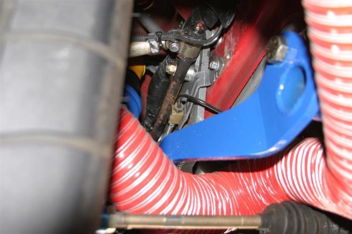
1 Installation Procedure GR40 S197 SLA Front Suspension System (Does not include Aluminum Spindle and Hub Instructions) Please take the time and read these instructions first! The GR40 S197 system is designed for installation by experienced mechanics. It is a very simple install if you have experience with serious high performance chassis. It can be done on the floor but is best done on a lift. These instructions are only a list of suggestions that we follow in our shop. They work for us. If you work out better or easier methods, we would be glad to hear from you. But please be careful. If you do not install things properly, following quality standards of skilled mechanical work, you can damage parts, the car, or injure yourself and/or others. Removal: Remove entire front suspension and #1 and #2 cross member. This can be done by completely disassembling one part at a time, or in sub-assemblies. The following steps are for removal in three sub-assemblies. Note: Although not required we remove the front bumper cover and both front fenders to make the installation easier and prevent damage to fenders while installation is performed. 1. Using an engine support cradle, secure engine in place. Caution: You will be underneath the engine with no other support! Be sure to do this properly or serious injury or vehicle damage could result. Fig 1 2. Remove upper radiator retention brackets. 3. Support radiator with straps or bungees. It must be held up in the stock or higher position. Fig 2 4. Remove lower steering shaft from Steering rack. 5. Disconnect anti-roll bar links from struts. 6. Remove brake lines from #1 cross member (Supporting radiator and anti-roll bar) Fig 3 Page 1 of 14


2 7. Remove #1 cross member with anti-roll bar attached. Fig 4,5 8. Remove motor mount bolts. Fig 6 Page 2 of 14


3 9. Disconnect brakes and ABS cables. 10. Drain power steering reservoir and disconnect hoses from steering rack. Fig Support the #2 cross member securely. Fig Remove all #2 cross member retaining nuts and bolts. 13. Remove strut mounting nuts at top of strut towers. Fig Carefully lower #2 cross member with suspension and steering rack attached and remove. Fig 10,11 Caution: Have someone on each side holding each strut while lowering so struts won t flop over and damage the fenders, or cause the assembly to tumble off of support. Page 3 of 14


4 Installation: 1. Position the front cradle into place and install only the four forward mounting bolts (that used to attach #1 cross member and the four rear most lower mounting bolts down low under the floor. Tighten to snug. DO NOT INSTALL THE FOUR UPPER NUTS YET. Fig 16,17 Note: You may want to check the alignment of the K member to the frame, by using plumb bobs. The same method as all other GR40 front ends should be employed. See K member and A-arm install on our website at: HOWEVER, it should be noted that in our experience no s197 cradle has required plumb bob alignment unless the car has been crashed or otherwise heavily abused. 2. Tighten the installed 4 forward cradle mounting nuts and 4 rear bolts to Ford OEM Torque specifications. 3. Prepare for mounting the inboard reinforcement brackets that sit in place on top of the sub frame on each side, inboard of the apron (under hood next to engine). Do this by modifying the tang of the four long #2 upper cradle bolts so that the bolts will fit properly into the brackets. Be careful not to damage the A/C lines. Fig 12 13,14,15 Page 4 of 14


5 4. Install motor mounts on Cradle. If using solid motor mounts, install them now and remove engine cradle and supports. If using rubber mounts, the hole in the engine mount brackets on block may need to be enlarged on some models. Fig Remove rubber grommets from discarded #1 cross member and install them in the radiator support brackets of the cradle. Reinstall the radiator and upper retention brackets, removing radiator support straps or bungees. Page 5 of 14


6 6. Remove the fender liners 7. Remove the brake line hold downs on the side of sub frame and release the wiring harness hold downs so that the harness can be relocated on the aprons to facilitate positioning of towers. Page 6 of 14


7 8. Install towers, be sure left is on left and right on right. Fit them under the wiring as shown. 9. Use the original nuts and tighten to Ford factory OEM specifications. 10. Locate the two upper tower mounting holes You can drill 7/16 holes though the apron using the tower as a drill guide, or you can blind punch thought the holes in the tower and then remove the tower and drill using a roto broach, This take more time but is a cleaner install. (Shown) 11. These holes should line up with the holes in the inboard reinforcement bracket. If not, wallow out the holes in the apron until they align well enough to install the 3/8 bolts. Before final install of these 3/8 bolts, be sure to install the supplied spacers in between the towers and the apron. Install loosely. Page 7 of 14


8 12. Snug all mounting fasteners ands then torque to specificatin on chart. Caution: When drilling, be sure to limit depth of drill so as not to damage A/C lines inboard of apron! 13. Reposition wiring harnesses as shown, reinserting all hold downs possible. Page 8 of 14

 16. Reinstall fender liners trimming as required to facilitate wiring relocation and towers. 17.")
9 14. Reposition brake lines to clear tower and upper control arm. If you are installing Griggs 4on4 brakes system, the hoses and fitting supplied will attach to frame to secure lines. If not, we recommend using an Adele clamp on the brake line to hold it in place on side of sub frame. 15. NOTE: This step is a change as of 2014 affecting all 2005 up Installations. Install upper mini tower support bolt and spacer to strut towers. Install all bolts before tightening any. Torque to specifications on chart. (Previously used vertical support bar as seen in other images has been deleted) 16. Reinstall fender liners trimming as required to facilitate wiring relocation and towers. 17. If headers are being installed, now is a good time to do so. There is lots of room. If long tube headers are being used, you may have a problem with the steering shaft clearance since it is relocated inboard. We offer angle mount steering rack bushings to provide additional exhaust to steering shaft clearance. 18. Install rear brake load support aluminum plate. Shim as required for clearance to bell housing bolts. Do not mount to Bell housing unless this is a track only vehicle and the engine and rotation parts have been precision balanced. (Drawing) 19. Install steering rack and assemble and connect hoses. It is advised to use a larger power steering cooler, along with AN fittings and hose. Due to the many varied vehicle usages and applications, these are not supplied by Griggs Racing as these parts usually require a custom installation. Contact our tech line for help if you have trouble finding what you need. 20. Install new steering shaft rack adaptor. Torque as per chart. 21. Install tie rod ends on rack. 22. Install lower control arms. Torque mounting bolts to spec on chart. Note: Outer strut link bolt and strut link jam nuts are supplied finger tight to facilitate installation. After installation be sure to tighten bolt and jam nuts as per chart. Do not allow aluminum tube to turn, this will make setup much more difficult. Page 9 of 14

. Set camber and caster to initial settings as per chart, and zero the toe.")
10 23. Install upper control arms, be sure to install cross-shaft back side spacer washers. Torque mounting nuts to specifications on chart. 24. Install spindles and hubs. Torque ball joint nuts and steering arm bolt to specifications on chart. Be sure to use thread locker on lower ball joint nut and install the cotter pin in the upper joint. Suggestion: Apply a small amount of anti-seize to the taper on the ball joints to facilitate service removal in future. Note: At this point we perform a preliminary alignment. If vehicle is truly level, hold spindle at ride height. (See ride height char). Set camber and caster to initial settings as per chart, and zero the toe. A simple angle finder held against the machined surfaces of the Aluminum spindle will suffice. Be sure steering rack is locked in straight ahead position (centered). Use whatever method works for this. A simple squeeze grip clamp on the steering wheel to a bar across the doors will suffice. 25. Set Bump steer, if desired. Note: The system is designed for use with 18 inch or larger diameter wheels. With wheels smaller than 18 shortening of the Bump steer sleeve may be required and true bump steer cannot be attained. Our recommendations: Just run the car with the supplied aluminum spacers and recommended caster angles. We have found that bump-in seems to work best on this system on current DOT track tires. The exact amount depends on tire make, size, and compound and driver preference. But there is very little difference in vehicle feel or performance from small bump steer settings on turn in, as compared to the strut cars. The supplied spacer should make the bump steer close if not perfect. 26. Install anti-roll bar (ARB) assembly: A) Install jam nuts on 5/8 rod ends and screw into weldments on cradle. They should be set so center of ball is 2.5 inches below rail. Leave jam nuts loose until ARB is final installed. B) Insert bolts and spacers into pivot holes of anti-roll bar arms. Assemble onto rod ends attached to cradle. C) Check spacing between ARB arm and rod end each side. Minimize this distance with appropriate shims before tightening bolts. Torque fasteners and jam nuts to specs on chart. D) Install end links and spacers as shown. Be sure to leave one end link disconnected until after ride height and corner weights are set. Page 10 of 14
11 Note: It is recommended that the rear hole on the control arm and the center hole on the ARB arm be used initially. Almost all cars run in this position and need no further rate adjustment. 27. Assemble coil-over and adjust spring seat to zero free play and then back off one turn. 28. Install coil-overs spring down (upside down). Torque to spec on chart. 29. Install brakes, tie off the brake lines. You may need to be creative re fastening the steel lines to the new radiator core support cross tube on the cradle. We simply use ¼ wide tie wraps with steel tabs. 30. Install brake duct brackets and ABS sensors if used. 31. Tie off brake lines to center of radiator support. ** See supplemental sheet of images in addendum for pluming Griggs Racing Supplied Brakes. 32. Install wheel and tires. 33. Set ride height, scale and align. Recommended initial settings are in alignment chart. 34. Install final anti-roll bar link. With car level and loaded, so that the bar is will not be preloaded, with the car sitting level and wheels straight. 35. Tighten all Jam Nuts with hand wrenches. Use good judgment. Over tightening may cause problems. 36. Lubricate upper control arm grease fittings with synthetic extreme pressure lubricants. We recommend Amsoil or Redline products. Anti-seize works as well. 37. Before driving check that wheels do not contact the tie rods or steering arms at full lock. They need about 3/8 clearance or they may contact at full bump travel while at lock. If they do not have enough clearance, additional steering stops can be added to the race under the boots. We supply them with all the stops necessary for our GR40 Toy series cars, different wheels and purposes may require more stop or perhaps less. 6 mm stops are available from Ford dealers, part number F-N S. Other thicknesses are available however we have not been able to determine a consistent part number for them. If you find out, please let us know. It is recommended that the jam nuts and all other fasteners be checked after the first outing on track. Periodic inspection of all parts and bolt torque is a requirement for safety and longevity of components. Lubricate ball joints and upper control arms every 3000 miles or every track event. We recommend Amsoil or Redline lubricants. Page 11 of 14
12 Fastener Torque Specifications Location or Component Size Grade Torque (Ft-Lbs) Cradle Mounting, Forward 12mm 10.9m 85 Cradle Mounting, Rearward 12mm 10.9m 85 Cradle Mounting, Center 12mm 10.9m 85 Tower (UCA and Shock Mount) 3/8-24 SAE 8 44 Tower Upper Support 3/8-24 SAE 8 44 Lower Control Arm Pivots at Cradle 5/8-18 SAE Lower Control Arm at Ball Joint 1/2-20 SAE 8 85 Upper Control Arm Mount Nuts 7/16-20 SAE 5 55 Upper Control Arm Assy Bolts 7/16-20 SAE 5 55 Steering Rack Mounting Bolts 1/2-20 SAE 8 75 Steering Shaft Upper Pinch Bolt 8mm m 18 Steering Shaft Lower Pinch Bolt 5/16-18 NC 8 18 Ball Joint, Lower, Nut (USE Loctite 242) 3/4-16 SAE Ball Joint, Upper, Nut (Use Cotter pin) 5/8-18 SAE Anti-Roll Bar Mounting Bolts 5/8-18 SAE Anti-Roll Bar Linkage Bolts 7/16-20 SAE 8 55 Steering Shaft to Tie Rod End Bolt 5/8-18 SAE Coil Over Fasteners 1/2-13 NC 3 65 All Jam nuts Use good judgment with hand wrenches. Preliminary Set Up Specifications Note: Ride Height is measured at bottom of front cradle rear mounting flange (the plate the bolts go through, not the lower box gusset). 30 psi in all tires, car level side to side, driver in seat and full of fuel. 48.5% initial cross weight recommended. GR40 ST and TT with 2 drop Aluminum Spindle Track Use Street Use With Hoosier 295/ Diameter With Hoosier 315/ Diameter With Toyo RA1 275/35 R Diameter With Toyo RA1 305/35 R Diameter GR40 ST and TT with Steel Spindle Track Use Street Use With Hoosier 295/ Diameter With Hoosier 315/ Diameter With Toyo RA1 275/35 R Diameter With Toyo RA1 305/35 R Diameter Alignment Track Use Street Use Camber -2.0deg -1.0deg Caster 6.5deg 6.5deg Toe 0 1/16 Total Page 12 of 14


13 Front Brake Plumbing Addendum. These are examples of Griggs Supplied Brakes Installed With Griggs supplied Hoses and adaptors. Page 13 of 14

14 Page 14 of 14
GR40 SLA Installation and Set Up Instructions.
 GR40 SLA Installation and Set Up Instructions. Read these instructions completely before beginning. These instructions are written for experienced installer/technicians with a strong idea as to how a chassis
Chevy Nova Pro-Touring Front Suspension Installation Instructions
 1962-1967 Chevy Nova Pro-Touring Front Suspension Installation Instructions 1-800-984-6259 www.totalcostinvolved.com 1 Pro-Touring Clip A-Arm Assembly Sway Bar Assembly Fender Panel Kit 8 7/16-20 * 1 ¼
USE THE PARTS LIST BELOW TO MAKE SURE YOUR KIT IS COMPLETE BEFORE INSTALLATION. IF ANY PIECES ARE MISSING, PLEASE CONTACT:
 1962-1967 Chevy Nova Pro-Touring Front Suspension Installation Instructions Tech line: 1-855-693-1259 www.totalcostinvolved.com Read and understand these instructions before starting any work! USE THE
INSTRUCTION S G-Comp Front Suspension: Chevy Nova Speedway Motors, Inc. 2017
 INSTRUCTION S 350-100 G-Comp Front Suspension: 62-67 Chevy Nova Speedway Motors, Inc. 2017 Kit Contents: 91035700 G-Comp Bare Subframe 350101 G-Comp Support Tubes 91035702 G-Comp Front Subframe Hardware
INSTRUCTION S G-Comp Front Suspension: Chevy Camaro Speedway Motors, Inc Kit Contents:
 INSTRUCTION S 350-500 G-Comp Front Suspension: 70-81 Chevy Camaro Speedway Motors, Inc. 2017 Kit Contents: 350500.1 G-Comp Subframe, Camaro 350500.2 G-Comp Sway Bar Kit, Camaro 350500.3 Hardware Kit, G-Comp
Installation Notes: #86000-R Race Series +3.5 L/T Kit
 159 North Maple St. Unit J, CORONA CA 92880 P. 951-737-9682 F. 951-737-9006 WWW.CHAOSFAB.COM Installation Notes: #86000-R Race Series +3.5 L/T Kit Factory manual is recommended for removal and re-installation
63162K 2015 Chevrolet Colorado 4WD Leveling Kit w/ 1 Rear Lift Kit
 PRO COMP SUSPENSION 63162K 2015 Chevrolet Colorado 4WD Leveling Kit w/ 1 Rear Lift Kit This document contains very important information that includes warranty information and instructions for resolving
Part # Cougar CoilOver System
 Front Components: 1 12103510 HQ Series Front CoilOvers 1 12102899 Lower StrongArms 1 12103699 Upper StrongArms 1 12109100 Front MuscleBar w/ PosiLinks 350 S. St. Charles St. Jasper, In. 47546 Ph. 812.482.2932
Part # Mustang Complete HQ Series Coil-Over Kit
 350 S. St. Charles St. Jasper, In. 47546 Ph. 812.482.2932 Fax 812.634.6632 www.ridetech.com Front Components: Part # 12090210 64-66 Mustang Complete HQ Series Coil-Over Kit 1 12093509 HQ Series Front Coil-Overs
Global West Suspension 655 South Lincoln Ave San Bernardino Ca Phone Fax Web address globalwest.
 Global West Suspension 655 South Lincoln Ave San Bernardino Ca. 92408 Phone 877-470-2975 Fax 909-890-0703 Web address globalwest.net Mustang coilover instruction sheets for 64-66 Kit includes the following
RHINO SUSPENSION SYSTEM INSTALLATION INSTRUCTIONS
 PARTS INCLUDED: 2 FRONT UPPER A-ARMS 2 FRONT LOWER A-ARMS 2 UNI-BALL JOINTS 2 UNI-BALL JOINT STUDS 2 UNI-BALL JOINT CAPS 2 RETAINING RINGS 1 FRONT SHOCK ASSEM. 2 DELRON STEERING STOPS 2 SHOCK MOUNT SPACERS
'99-03 CHEVROLET/GMC IFS 4WD 6" SUSPENSION SYSTEM P/N INSTALLATION INSTRUCTIONS
 1/16/04 '99-03 CHEVROLET/GMC IFS 4WD 6" SUSPENSION SYSTEM P/N. 10-41099 INSTALLATION INSTRUCTIONS NOTE: Each Lift Kit and options to Lift Kits are packaged separately. Therefore, installation procedures
AEV30308AA Last Updated: 05/31/18. 4 DUALSPORT sc SUSPENSION system for RAM 1500 air ride standard and rebel INSTALLATION GUIDE
 AEV30308AA Last Updated: 05/31/18 4 DUALSPORT sc SUSPENSION system for RAM 1500 air ride standard and rebel INSTALLATION GUIDE PLEASE READ BEFORE YOU START TO GUARANTEE A QUALITY INSTALLATION, WE RECOMMEND
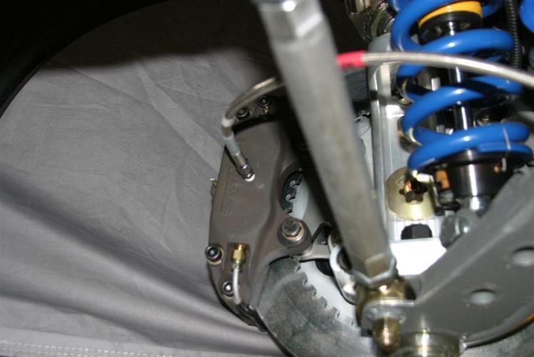
First, check and record the camber and caster readings, they will be adjusted later.
 First, check and record the camber and caster readings, they will be adjusted later. The caliper-mounting bosses are machined perpendicular to the spindle so they are an excellent place for the level.
Part # Impala Air Suspension System
 350 S. St. Charles St. Jasper, In. 47546 Ph. 812.482.2932 Fax 812.634.6632 www.ridetech.com Part # 11040298 58 Impala Air Suspension System Front Components: 1 11053001 HQ Series Front Shockwaves 1 11052899
99-04 GT. Hellion Power Systems Mustang GT Kit Instructions
 Hellion Power Systems 99-04 Mustang GT Kit Instructions Part 1 Hellion recommends that the front suspension system be installed either by trained professionals or by 5.Remove rack bolts K-Member Installation
Installation Instructions S197 Mustang Xtreme-Grip Coil Over System CCK /S
 Sonoma Raceway Boise, ID 83704 p 415.489.0866 c 415.425.0030 www.cortexxracing.com Installation Instructions S197 Mustang Xtreme-Grip Coil Over System CCK-40-1000/S 2005-2014 Mustang Shelby/Boss/GT (8.8
INSTALLATION INSTRUCTIONS Chevrolet Nova Superide II Independent Front Suspension
 INSTALLATION INSTRUCTIONS 1962 1967 Chevrolet Nova Superide II Independent Front Suspension Please read these instructions completely before starting your installation. Assemble suspension on vehicle before
KIT # CSS-C SUSPENSION LIFT KIT
 14385 Veterans Way Moreno Valley, CA 92553 Phone: (951) 571-0212 Fax: (951) 571-0215 2001-2010 CHEVROLET SILVERADO 1500 AND 2500 HD 4WD AND 2WD PICK-UP 1999-2010 CHEVY 2500 4WD PICK-UPS 2001-2010 2500
Part # Impala Air Suspension System
 350 S. St. Charles St. Jasper, In. 47546 Ph. 812.482.2932 Fax 812.634.6632 www.ridetech.com Part # 11060298 59-64 Impala Air Suspension System Front Components: 1 11053001 HQ Series Front Shockwaves 1
Note: The transmission mount just happened to be upside down in this picture. (c) 2015 Total Cost Involved Engineering, Inc. All Rights Reserved.
 2015 Total Cost Involved Engineering, Inc. All Rights Reserved.") 1970-1981 Chevy Camaro & Pontiac Firebird Custom IFS Installation Instructions 1-855-693-1259 www.totalcostinvolved.com CHECK ALL PARTS INCLUDED IN THIS KIT TO THE PARTS LIST BEFORE INSTALLATION. IF ANY
1970-1981 Chevy Camaro & Pontiac Firebird Custom IFS Installation Instructions 1-855-693-1259 www.totalcostinvolved.com CHECK ALL PARTS INCLUDED IN THIS KIT TO THE PARTS LIST BEFORE INSTALLATION. IF ANY
MM Caster/Camber Plates, (MMCC7989)
") 3430 Sacramento Dr., Unit D San Luis Obispo, CA 93401 Telephone: 805/544-8748 Fax: 805/544-8645 www.maximummotorsports.com MM Caster/Camber Plates, 1979-89 (MMCC7989) IMPORTANT: The bearing used in our
3430 Sacramento Dr., Unit D San Luis Obispo, CA 93401 Telephone: 805/544-8748 Fax: 805/544-8645 www.maximummotorsports.com MM Caster/Camber Plates, 1979-89 (MMCC7989) IMPORTANT: The bearing used in our
Next, set the bar level and tighten it down. Do this on both the driver and passenger sides.
 Next, set the bar level and tighten it down. Do this on both the driver and passenger sides. Using two tape measures, measure the outside width at the front and the rear of the tubes. The front dimension
INSTALLATION GUIDE Bolt-On Drag-Race Strut Clip Chevy II
 INSTALLATION GUIDE 7702 Bolt-On Drag-Race Strut Clip 1962-67 Chevy II Description: STRUT CLIP 4130 BOLT ON 62-67 CHEVY II, INCLUDES 4130 ROUND TUBE FRAME CLIP, DOUBLE-ADJUSTABLE STRUTS, ADJUSTABLE-HEIGHT
Part # Impala Fixed Valving Coil-Over Suspension Package
 350 S. St. Charles St. Jasper, In. 47546 Part # 11060109 59-64 Impala Fixed Valving Coil-Over Suspension Package Front Components: 1 11053509 RQ Series Front Coil-overs 1 11052899 Front Lower StrongArms
Part # Mustang Coil-Over System
 350 S. St. Charles St. Jasper, In. 47546 Ph. 812.482.2932 Fax 812.634.6632 www.ridetech.com Front Components: 1 12093509 HQ Series Front Coil-Overs Part # 12090201 64-66 Mustang Coil-Over System 1 12099599
Installation Instructions S550 Mustang Xtreme-Grip Coil Over System CCK
 Sonoma Raceway Boise, ID 83704 p 415.489.0866 www.cortexxracing.com Installation Instructions 2015-2017 S550 Mustang Xtreme-Grip Coil Over System CCK-50-1000 2015-2017 Mustang GT, ECO Boost, and GT350/R
96-04 tt. Hellion Power Systems Mustang Twin Turbo Kit Instructions
 96-04 tt Hellion Power Systems 1996-2004 Mustang Twin Turbo Kit Instructions 1. Disconnect battery and elevate front end of car on either Jack stands or a lift if available 2.Lock steering wheel and remove
This file is available for free download at
 This file is available for free download at http://www.iluvmyrx7.com This file is fully text-searchable select Edit and Find and type in what you re looking for. This file is intended more for online viewing
INSTALLATION INSTRUCTION 88148
 INSTALLATION INSTRUCTION 88148 Rev C For Rancho Suspension Systems RS6548, RS6549 & RS6550: GM 2500HD, 2500, and 1500HD Trucks READ ALL INSTRUCTIONS THOROUGHLY FROM START TO FINISH BEFORE BEGINNING INSTALLATION
C-10 StrongArms
 Part # 11342699(63-70)/11352699(71-72) - C10 StrongArms Recommended Tools 1963-1972 C-10 StrongArms Installation Table of contents Page 2... Included components Page 3... Upper Control Arm Components Page
Part # Mustang Complete SA CoilOver Kit
 Front Components: 350 S. St. Charles St. Jasper, In. 47546 Ph. 812.482.2932 Fax 812.634.6632 www.ridetech.com Part # 12100210 67-70 Mustang Complete SA CoilOver Kit 1 12103510 Single Adjustable Front CoilOvers
Slide the billet aluminum cap over the bushing and secure with the 3/8-16 x 2 1/2 socket head allen and locknuts provided.
 Slide the billet aluminum cap over the bushing and secure with the 3/8-16 x 2 1/2 socket head allen and locknuts provided. Put the urethane bushings into the upper antiroll-bar-link eyebolt. Coat the bushings
Part # Mustang Tru-Turn Suspension Package
 350 S. St. Charles St. Jasper, In. 47546 Ph. 812.482.2932 Fax 812.634.6632 www.ridetech.com Part # 12099599 64-66 Mustang Tru-Turn Suspension Package Front Components: 1 12093699 Upper Strong Arms 1 12092899
'88-'00 CHEVROLET/GMC IFS 4WD(8LUG) OLD BODY STYLE 6" SUSPENSION SYSTEM P/N
 OLD BODY STYLE 6 SUSPENSION SYSTEM P/N") 4/10/13 '88-'00 CHEVROLET/GMC IFS 4WD(8LUG) OLD BODY STYLE 6" SUSPENSION SYSTEM P/N. 10-41888 INSTALLATION INSTRUCTIONS APPLICATION WARNING: Applicable for hub mounted ABS sensor models only. Not for 1992-94
4/10/13 '88-'00 CHEVROLET/GMC IFS 4WD(8LUG) OLD BODY STYLE 6" SUSPENSION SYSTEM P/N. 10-41888 INSTALLATION INSTRUCTIONS APPLICATION WARNING: Applicable for hub mounted ABS sensor models only. Not for 1992-94
PN# Toyota Tacoma 4WD/2wd Pre Runner 6-Lug 2 1/2 Leveling Kit PRO COMP SUSPENSION. Suspension Systems that Work!
 PRO COMP SUSPENSION Suspension Systems that Work! PN# 65170 1996-2004 Toyota Tacoma 4WD/2wd Pre Runner 6-Lug 2 1/2 Leveling Kit This document contains very important information that includes warranty
03-04 Mach 1. Hellion Power Systems Mach 1 Kit Instructions
 Hellion Power Systems 03-04 Mach 1 Kit Instructions Part 1 Hellion recommends that the front suspension system be installed either by trained professionals or by 5.Remove rack bolts K-Member Installation
Part # Mustang Complete CoilOver Kit
 Front Components: Part # 12100109 67-70 Mustang Complete CoilOver Kit 1 12103509 Non Adjustable Front CoilOvers 1 12102899 Lower StrongArms 1 12103699 Upper StrongArms Rear Components: 1 12106509 Non Adjustable
Chevrolet 3100 IFS Kit
 1947-54 Chevrolet 3100 IFS Kit Congratulations on your purchase on what we believe is the finest IFS kit available for 1947-54 Chevrolet pickups with stock frames. We have invested many hours into designing
INSTALLATION MANUAL TOYOTA TUNDRA 5 SUSPENSION SYSTEM PART # 55905
 PART NUMBER : 55905 1999 2003 TOYOTA TUNDRA 5 SUSPENSION SYSTEM PARTS LIST: Part # Description Qty. 55900-01 Driver Side Spindle 1 55900-02 Passenger Side Spindle 1 55905-03 Rear brake proportioning valve
Pro/Series 2000 Tubular A-Arm Front Suspension
 11 Mennonite Church Road Spring City, PA 19475 (610) 948-7303 Installation Instructions Pro/Series 2000 Tubular A-Arm Front Suspension (Pinto-Style) CAUTION!!! The most important requirement for a successful
INSTALLATION INSTRUCTIONS
 INSTALLATION INSTRUCTIONS 2005-2012 Nissan Xterra/Frontier / Pathfinder PART NUMBERS: NP17500, NP17525, NP17550 FRONTIER PARTS & CORRESPONDING HARDWARE LIST XTERRA PATHFINDER ABOVE LISTED 1/2 Metal Lock
Detroit Speed, Inc. ALUMA-Frame Front Suspension System Ford Mustang P/N:
 Detroit Speed, Inc. ALUMA-Frame Front Suspension System 1964.5-1970 Ford Mustang P/N: 032050 INTRODUCTION All aluminum front suspension system for 1964.5-1970 Mustangs featuring DSE s unique suspension
INSTALLATION INSTRUCTIONS `64 ½ - 70 MUSTANG, HEIDTS IFS, PRO-G GEN II P/N: MTF-201
 INSTALLATION INSTRUCTIONS `64 ½ - 70 MUSTANG, HEIDTS IFS, PRO-G GEN II P/N: MTF-201 Please read these instructions completely Before starting your installation. Assemble suspension on vehicle before powder-coating
Chrysler A-Body Tubular A-Arms Installation Instructions A-ARM INSTALLATION
 1967-1976 Dodge Demon 1112 67-72 Chrysler A-Body Tubular A-Arms Installation Instructions Thank you for your purchase of this Hotchkis Performance product. Your A-Arm set was designed with the performance
INSTALLATION GUIDE. TCP TIER-14 Bump Steer Conversion Kit - Early Mustang to Late Spindle
 READ ALL INSTRUCTIONS COMPLETELY AND THOROUGHLY UNDERSTAND THEM BEFORE DOING ANYTHING. CALL TOTAL CONTROL PRODUCTS TECH SUPPORT (916) 388-0288 IF YOU NEED ASSISTANCE. INSTALLATION GUIDE TCP TIER-14 Bump
cfr angle kit INSTALLATION INSTRUCTIONS: 2009-present nissan 370z z infiniti g37 v36 Part Numbers: VOO-akns-0400
 cfr angle kit INSTALLATION INSTRUCTIONS: 2009-present nissan 370z z34 2008-2013 infiniti g37 v36 Part Numbers: VOO-akns-0400 We recommend that installation of all Voodoo13 parts be completed by a professional
Part # Mustang Tru-Turn Suspension Package
 350 S. St. Charles St. Jasper, In. 47546 Ph. 812.482.2932 Fax 812.634.6632 www.ridetech.com Part # 12099599 64-66 Mustang Tru-Turn Suspension Package Front Components: 1 12093699 Upper Strong Arms 1 12092899
Part # Impala Level 1 Complete Coil-Over System RQ Series
 350 S. St. Charles St. Jasper, In. 47546 Ph. 812.482.2932 Fax 812.634.6632 www.ridetech.com Part # 11290109 65-66 Impala Level 1 Complete Coil-Over System RQ Series Front Components: 1 11283509 RQ Series
Alignment Spec. Power Rack & Pinion: 5 degrees positive Camber 0 degrees Toe-In 1/32
 333-TCIE237 1967-1969 Chevy Camaro Front Suspension 1968-1972 Chevy Nova Front Suspension 1967-1969 Pontiac Firebird Front Suspension 1-800-984-6259 www.totalcostinvolved.com 1967-1969 Chevy Camaro Front
Part # Mustang Complete CoilOver Kit
 Front Components: 1 12103509 Front CoilOvers 1 12102899 Lower StrongArms 1 12103699 Upper StrongArms 350 S. St. Charles St. Jasper, In. 47546 Ph. 812.482.2932 Fax 812.634.6632 www.ridetech.com Part # 12100109
INSTALLATION INSTRUCTION 88581
 INSTALLATION INSTRUCTION 88581 FOR RANCHO SUSPENSION SYSTEM RS6581B: DODGE RAM READ ALL INSTRUCTIONS THOROUGHLY FROM START TO FINISH BEFORE BEGINNING INSTALLATION Rev C IMPORTANT NOTES! WARNING: This suspension
INSTALLATION INSTRUCTIONS 64 ½ - 70 SUPERRIDE II INDEPENDENT FRONT SUSPENSION BX-350 FOR COYOTE AND MOD ENGINES
 INSTALLATION INSTRUCTIONS 64 ½ - 70 SUPERRIDE II INDEPENDENT FRONT SUSPENSION BX-350 FOR COYOTE AND MOD ENGINES Please read these instructions completely before starting your installation. Assemble suspension
2. Remove front wheels.
 Read all instructions before beginning work. Following instructions in the proper sequence will ensure the best and easiest installation. Thank you for purchasing Maximum Motorsports Caster/Camber Plates.
Carli Suspension Front Instructions
 Carli Suspension Front Instructions 94-08 DODGE 2500-3500 4X4 SUSPENSION SYSTEM Note: Prior to installation, carefully inspect the vehicle=s steering and drive train components. Be sure to check ball joints,
1 of 12 8/25/2017, 4:29 PM
 1 of 12 8/25/2017, 4:29 PM STANDARD PROCEDURE - WHEEL ALIGNMENT PRE-WHEEL ALIGNMENT INSPECTION Before any attempt is made to change or correct the wheel alignment, the following inspection and necessary
LONGTRAVEL SUSPENSION FOR CLUB CAR Model
 INSTALLATION INSTRUCTIONS LONGTRAVEL SUSPENSION FOR CLUB CAR 1980 2003 Model C-7-06 TABLE OF CONTENTS Progressive Suspension Kit... 2 Kit Contents...3-6 Disassembly...7-17 Assembly...18-29 Rack & Pinion
Installation Instructions
 Installation Instructions Eibach Springs, Inc. 264 Mariah Circle Corona, California 92879-1751 USA Tech Support 800-222-8811 Ext 114 CASTER / CAMBER PLATE KIT # 5.3510K 1990-1993 Ford Mustang All FOX Body
INSTALLATION INSTRUCTION Rev A
 INSTALLATION INSTRUCTION 88587 Rev A FOR RANCHO SUSPENSION SYSTEM RS6587B: 2009 DODGE RAM 1500 READ ALL INSTRUCTIONS THOROUGHLY FROM START TO FINISH BEFORE BEGINNING INSTALLATION IMPORTANT NOTES! WARNING:
Installation Instructions
 Installation Instructions Eibach Springs, Inc. 264 Mariah Circle Corona, California 92879-1751 USA Tech Support 800-222-8811 Ext 114 CASTER / CAMBER PLATE KIT # 5.3518K 1999-2004 SN95 Ford Mustang - All
1970 Trans-Am Mustang Front Suspension Instructions. Manual, Volume One, Chassis. Special instructions and precautions will be given
 1970 Trans-Am Mustang Front Suspension Instructions 1. This kit was designed to be used in conjunction with the Rear Suspension kit. 2. This conversion follows standard procedures as described in the 1970
INSTALLATION INSTRUCTION 88146
 INSTALLATION INSTRUCTION 88146 Rev H FOR RANCHO SUSPENSION SYSTEM RS6547: 4WD SUBURBAN/YUKON XL, 4WD TAHOE/YUKON, & 4WD AVALANCHE READ ALL INSTRUCTIONS THOROUGHLY FROM START TO FINISH BEFORE BEGINNING
INSTALLATION MANUAL TOYOTA TACOMA 5 SUSPENSION SYSTEM PART # 54900
 PART NUMBER : 54900 1996 2004 TOYOTA TACOMA 5 SUSPENSION SYSTEM PARTS LIST: Part # Description Qty. 55900-01 Driver Side Spindle 1 55900-02 Passenger Side Spindle 1 54900-01 Rear brake proportioning valve
73-87 C-10 Coilover System
 Part # 11360201-73-87 C10 CoilOver System Front Components: 11362699 Front StrongArm System 11369300 Front Spindles and Caliper Brackets 11363510 Front Coilovers 11369100 Front MuscleBar Recommended Tools
Part # Impala TQ CoilOver Suspension Package
 350 S. St. Charles St. Jasper, In. 47546 Ph. 812.482.2932 Fax 812.634.6632 www.ridetech.com Part # 11040311 58 Impala TQ CoilOver Suspension Package Front Components: 1 11053511 TQ Series Front Coilovers
INSTALLATION INSTRUCTIONS CHEVY C-10 4-Link Rear End
 INSTALLATION INSTRUCTIONS 73-87 CHEVY C-10 4-Link Rear End Please read these instructions completely before starting your installation. Assemble suspension on vehicle before powder-coating to ensure proper
US Patent You will find many features that set our Caster/Camber Plates apart from the rest.
 3430 Sacramento Dr., Unit D San Luis Obispo, CA 93401 Telephone: 805/544-8748 Fax: 805/544-8645 www.maximummotorsports.com US Patent 6485223 Read all instructions before beginning work. Following instructions
INSTALLATION INSTRUCTIONS CHEVROLET NOVA (NVR-301) INDEPENDENT REAR SUSPENSION
 INDEPENDENT REAR SUSPENSION") INSTALLATION INSTRUCTIONS 68-74 CHEVROLET NOVA (NVR-301) INDEPENDENT REAR SUSPENSION Please read these instructions completely before starting your installation. Assemble suspension on vehicle before powder-coating
INSTALLATION INSTRUCTIONS 68-74 CHEVROLET NOVA (NVR-301) INDEPENDENT REAR SUSPENSION Please read these instructions completely before starting your installation. Assemble suspension on vehicle before powder-coating
(800) MON-FRI 7AM-5PM PST OR WEBSITE: ReadyLIFT.COM **Please retain this document in your vehicle at all times**
 MON-FRI 7AM-5PM PST OR WEBSITE: ReadyLIFT.COM **Please retain this document in your vehicle at all times**") IF your ReadyLIFT product has a damaged or missing part, please contact customer service directly. For warranty issues please return to the place of installation and contact ReadyLIFT. A NEW REPLACEMENT
IF your ReadyLIFT product has a damaged or missing part, please contact customer service directly. For warranty issues please return to the place of installation and contact ReadyLIFT. A NEW REPLACEMENT
CHECK ALL PARTS INCLUDED IN THIS KIT TO THE PARTS LIST BEFORE INSTALLATION. IF ANY PIECES ARE MISSING, PLEASE CONTACT: TOTAL COST INVOLVED
 333-TCIE237 1967-1969 Chevy Camaro Front End, 1968-1972 Chevy Nova Front End 1967-1969 Pontiac Firebird Front End Suspension Installation Instructions 1-855-693-1259 www.totalcostinvolved.com CHECK ALL
Adjustable Tie-rod Ends (Mm5TR-1)
") 3430 Sacramento Dr., Unit D San Luis Obispo, CA 93401 Telephone: 805/544-8748 Fax: 805/544-8645 www.maximummotorsports.com 2005-10 Adjustable Tie-rod Ends (Mm5TR-1) 3. Remove the front wheels. 4. Loosen
3430 Sacramento Dr., Unit D San Luis Obispo, CA 93401 Telephone: 805/544-8748 Fax: 805/544-8645 www.maximummotorsports.com 2005-10 Adjustable Tie-rod Ends (Mm5TR-1) 3. Remove the front wheels. 4. Loosen
CHEVY / GMC 1500HD / 2500HD 2WD 8 LUG 7 BASIC KIT
 85101 2000-2010 CHEVY / GMC 1500HD / 2500HD 2WD 8 LUG 7 BASIC KIT C8510-4 MAIN BOX KIT W/ HARDWARE 1) FRONT X MEMBER 1) REAR X MEMBER 2) TORSION BAR DROPS 1) LEFT BUMP STOP 1) RIGHT BUMP STOP 2) SWAY BAR
Part # GM F Body Complete CoilOver System
 350 S. St. Charles St. Jasper, In. 47546 Ph. 812.482.2932 Fax 812.634.6632 www.ridetech.com Part # 11170109 70-81 GM F Body Complete CoilOver System Front Components: 1 11173509 Front Fixed Valving CoilOvers
60-65 Falcon, Comet & Ranchero Coil Spring IFS
 60-65 Falcon, 62-65 Comet & 62-65 Ranchero Coil Spring IFS All engine installations with this front end will require a rear sump oil pan. 289-302 Small Block Ford Motors Milodon rear sump pan holds 7 quarts
2010 Camaro SS/V Underbody Brace Installation Instructions
 2010 Camaro SS/V6 20104 Underbody Brace Installation Instructions Thank you for your purchase of this Hotchkis Performance product. Your Underbody Brace set was designed with the performance and durability
Suspension System RS6582B
 Suspension System RS6582B Tahoe/Yukon READ ALL INSTRUCTIONS THOROUGHLY FROM START TO FINISH BEFORE BEGINNING INSTALLATION IMPORTANT NOTES! WARNING: This suspension system will enhance the off-road performance
07-UP AVALANCHE 7.5 KIT
 92120900R1 07-UP AVALANCHE 7.5 KIT Thank you for choosing Rough Country for your suspension needs. We appreciate your business!! This kit will not fit vehicles equipped with electric steering or trucks
Detroit Speed, Inc. Front Coilover Kit Race Double Adjustable Camaro P/N:
 Detroit Speed, Inc. Front Coilover Kit Race Double Adjustable 2010+ Camaro P/N: 030321 Item Quantity Description 1 2 Front Strut Assembly (Double Adjustable) 2 2 Coilover Spring 250# x 2.5"ID x 8"L 3 2
INSTALLATION INSTRUCTION 88051
 INSTALLATION INSTRUCTION 88051 For Rancho Suspension System RS6551: Chevrolet 2500 Suburban & 2500 Avalanche READ ALL INSTRUCTIONS THOROUGHLY FROM START TO FINISH BEFORE BEGINNING INSTALLATION Rev C IMPORTANT
2011+ Adjustable Tie-rod Ends (Mm5TR-2)
") 3430 Sacramento Dr., Unit D San Luis Obispo, CA 93401 Telephone: 805/544-8748 Fax: 805/544-8645 www.maximummotorsports.com 2011+ Adjustable Tie-rod Ends (Mm5TR-2) Instructions 1. Set the parking brake
3430 Sacramento Dr., Unit D San Luis Obispo, CA 93401 Telephone: 805/544-8748 Fax: 805/544-8645 www.maximummotorsports.com 2011+ Adjustable Tie-rod Ends (Mm5TR-2) Instructions 1. Set the parking brake
USE THE PARTS LIST BELOW TO MAKE SURE YOUR KIT IS COMPLETE BEFORE INSTALLATION. IF ANY PIECES ARE MISSING, PLEASE CONTACT:
 55-59 Chevy Truck Chassis Custom IFS & 4-Link Install Instructions Tech line: 1-855-693-1259 www.totalcostinvolved.com Read and understand these instructions before starting any work! USE THE PARTS LIST
Warning! READ BEFORE INSTALLING. Notice to Owner, Operator, Dealer and Installer
 Warning! READ BEFORE INSTALLING Notice to Owner, Operator, Dealer and Installer ReadyLIFT Off Road Suspension s Mid Travel and Long Travel suspension systems and components are designed for OFF ROAD USE
INSTALLATION INSTRUCTION 88073
 INSTALLATION INSTRUCTION 88073 Rev C FOR RANCHO SUSPENSION SYSTEMS RS6572 & RS6573: DODGE RAM READ ALL INSTRUCTIONS THOROUGHLY FROM START TO FINISH BEFORE BEGINNING INSTALLATION IMPORTANT NOTES! WARNING:
INSTALLATION INSTRUCTIONS 88029
 INSTALLATION INSTRUCTIONS 88029 FOR SUSPENSION SYSTEMS RS6503: JEEP WRANGLER (TJ) READ ALL INSTRUCTIONS THOROUGHLY FROM START TO FINISH BEFORE BEGINNING INSTALLATION REV F IMPORTANT NOTES! WARNING: This
INSTALLATION INSTRUCTION 89400
 INSTALLATION INSTRUCTION 89400 FOR RANCHO SUSPENSION SYSTEM RS66400B: 2012 RAM 1500 4WD. READ ALL INSTRUCTIONS THOROUGHLY FROM START TO FINISH BEFORE BEGINNING INSTALLATION Rev B IMPORTANT NOTES! WARNING:
Part # Mustang Complete NA CoilOver Kit
 Front Components: 350 S. St. Charles St. Jasper, In. 47546 Ph. 812.482.2932 Fax 812.634.6632 www.ridetech.com Part # 12090109 64-66 Mustang Complete NA CoilOver Kit 1 12093509 Non Adjustable Front CoilOvers
Installation Instructions. 6 Basic System FTS21060BK / FTS21061BK / FTS21042BK GM 2WD C1500 P/U ONLY
 Installation Instructions 6 Basic System FTS21060BK / FTS21061BK / FTS21042BK 2007-13 GM 2WD C1500 P/U ONLY 2007-13 GM 1500 Truck Basic System FTS21060BK / FTS21061BK / FTS21042BK 2007-13 GM 2WD C1500
Part # C-10 Level 2 Complete Air Suspension System
 350 S. St. Charles St. Jasper, In. 47546 Ph. 812.482.2932 Fax 812.634.6632 www.ridetech.com Part # 11340299 63-70 C-10 Level 2 Complete Air Suspension System Front Components: 1 11330999 Front CoolRide
INSTALLATION GUIDE. TCP STRD-07 Adjustable Strut Rods
 READ ALL INSTRUCTIONS COMPLETELY AND THOROUGHLY UNDERSTAND THEM BEFORE DOING ANYTHING. CALL TOTAL CONTROL PRODUCTS TECH SUPPORT (916) 388-0288 IF YOU NEED ASSISTANCE. INSTALLATION GUIDE TCP STRD-07 Adjustable
USE THE PARTS LIST BELOW TO MAKE SURE YOUR KIT IS COMPLETE BEFORE INSTALLATION. IF ANY PIECES ARE MISSING, PLEASE CONTACT:
 60-65 Ford Falcon Triangulated 4-Link Suspension Installation Instructions Tech Line: 1-855-693-1259 www.totalcostinvolved.com Read and understand these instructions before starting any work! USE THE PARTS
TOYOTA FJ CRUISER 6 SUSPENSION KIT
 92177000 TOYOTA FJ CRUISER 6 SUSPENSION KIT Thank you for choosing Rough Country for your suspension needs. Rough Country recommends a certified technician installs this system. In addition to these instructions,
Super Duty Front Air Bag Installation Instructions
 2005-2010 Super Duty Front Air Bag Installation Instructions Congratulations! You have just purchased the best engineered, highest quality front air suspension kit available on the market for your 2005-2010
97-06 JEEP TJ/LJ LONG ARM UPGRADE KIT
 921663U00 97-06 JEEP TJ/LJ LONG ARM UPGRADE KIT Thank you for choosing Rough Country for your suspension needs. This kit is an upgrade kit only. This kit includes frame mounting points and adjustable long
AEV30213AH Last Updated: 04/28/17. jk wrangler dualsport sc suspension INSTALLATION GUIDE
 AEV30213AH Last Updated: 04/28/17 jk wrangler 3.5 4.5 dualsport sc suspension INSTALLATION GUIDE PLEASE READ BEFORE YOU START TO GUARANTEE A QUALITY INSTALLATION, WE RECOMMEND READING THESE INSTRUCTIONS
PPM-8023 / PPM-8043 JEEP JK SYNERGY STAGE 3 SUSPENSION SYSTEM Version 1
 SYNERGY MFG. 870 INDUSTRIAL WAY, SAN LUIS OBISPO, CA (805) 242-0397 PPM-8023 / PPM-8043 JEEP JK SYNERGY STAGE 3 SUSPENSION SYSTEM Version 1 GENERAL NOTES: These instructions are also available on our website;
AEV30243AK Last Updated: 05/01/18. 3 Dualsport front suspension ram truck 2500/3500 INSTALLATION GUIDE
 AEV30243AK Last Updated: 05/01/18 3 Dualsport front suspension ram truck 2500/3500 INSTALLATION GUIDE PLEASE READ BEFORE YOU START TO GUARANTEE A QUALITY INSTALLATION, WE RECOMMEND READING THESE INSTRUCTIONS
Part # Chevy Level 2 CoilOver Suspension Package Two Piece Frame
 350 S. St. Charles St. Jasper, In. 47546 Ph. 812.482.2932 Fax 812.634.6632 www.ridetech.com Part # 11030210 55-57 Chevy Level 2 CoilOver Suspension Package Two Piece Frame Front Components: 1 11013510
Part # PLF FRONT SPACER LIFT KIT FORD F150 2WD & 4WD LINCOLN MARK LT 2WD & 4WD PRO COMP SUSPENSION
 PRO COMP SUSPENSION Suspension Systems that Work! Part # PLF09111 2.5 FRONT SPACER LIFT KIT 2004-2008 FORD F150 2WD & 4WD 2004-2008 LINCOLN MARK LT 2WD & 4WD This document contains very important information
4 & 6 4-Link Suspension Systems. Ford Super Duty 4WD Part#: ,
 Part#: 013013, 013014 4 & 6 4-Link Suspension Systems Ford Super Duty 4WD 2011-2016 Rev. 051817 491 W. Garfield Ave., Coldwater, MI 49036. Phone: 517-279-2135 E-mail: tech-bds@sporttruckusainc.com Read
~ Installing the Coil-Spring Front End ~
 1935-1940 Ford Car & 1935-1941 Ford Truck Chassis Coil-Spring Front & Leaf Spring Rear Tech line: 1-855-693-1259 www.totalcostinvolved.com Read and understand these instructions before starting any work!