LONGTRAVEL SUSPENSION FOR CLUB CAR Model
|
|
|
- Virginia Shelton
- 6 years ago
- Views:
Transcription
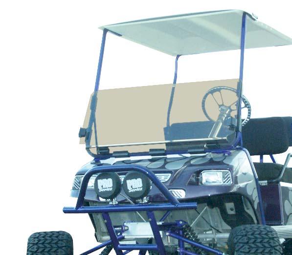
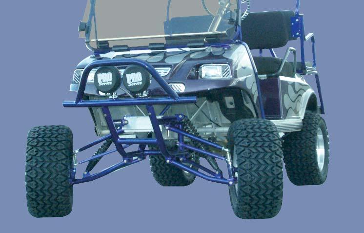
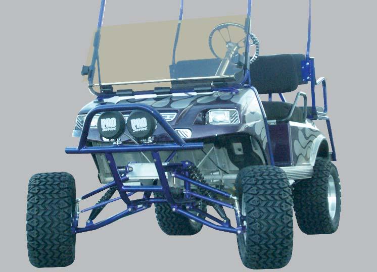
1 INSTALLATION INSTRUCTIONS LONGTRAVEL SUSPENSION FOR CLUB CAR Model C-7-06

2 TABLE OF CONTENTS Progressive Suspension Kit... 2 Kit Contents Disassembly Assembly Rack & Pinion Stiffener Assembly Contents Reinforcing Rack & Pinion Assembly Continued Finishing Touches


3 PROGRESSIVE SUSPENSION KIT AA CC DD BB EE FF ID Qty Product # Description AA 2 MS-7-01A Coil Over Dual Rate Shock 16 BB 1 INSTRUCTIONS Washer Usage Instructions CC 4 MS Shock Sleeves DD 4 MS Lower Eye Mount Washers EE 1 MS Spanner Wrench FF 1 MS Cam Adjuster Lubricant (3 gms) 02


4 KIT CONTENTS B A C E D F J I G H K M 03 O L N
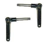
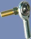
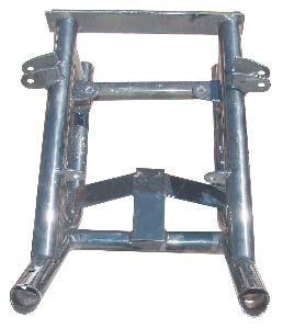
5 ID Qty Product # Description A 1 AFC-910 Sub Frame B 1 AFE-920 Lower A-Arm Passenger Side C 1 AFE-925 Lower A-Arm Driver Side D 1 AFC-920 Brushguard E 2 C /4 Shaft King Pin F 2 AFE-930 Upper J Arm G 1 AFC-960 Steering Shaft H 2 C /8 Tie Rod I 1 AFC-950 Pinch Plate J 1 MS-7-19 Passenger Side Spindle K 1 MS-7-18 Driver Side Spindle L 2 MS /2-20 Male Heim Joint M 2 MS /8-24 Male Heim Joint N 1 AFE-411 Universal Joint O 1 AFC-935 Rack And Pinion Assembly 04


6 KIT CONTENTS A C D B F G H I J E K L M N O P Q R S 05
7 ID Qty Product # Description A 16 AFH-210 Urethane Bushing B 2 HW-138 Round Tubing Plug C 20 HW /8 16 Nylock Nut/Grade 8 D 4 HW /8 24 Jam Nuts E 1 HW-23 LOCTITE Threadlocker F 2 HW /2 20 Jam Nut G 16 HW /8 Flat Washer USS H 2 HW /2 20 SAE Washer/Grade 8 I 2 HW /8 24 Nylon Insert Lock Nut J 4 HW /16 18 Nylon Lock Nut Zinc K 2 HW /8 x 16 x 1-1/2 H.H.C.S./Garde 2 Zinc L 6 HW /8 16 x 3-1/2 H.H.C.S./Grade 8 M 2 HW /8 16 x 5 Hex Bolt/Grade 8 N 4 HW /8 16 x 2 Bolts/Grade 8 O 4 HW /8 16 x 4-1/2 Bolts/Grade 8 P 2 HW /8 x 16 x 1-1/2 H.H.C.S./Grade 8 Q 2 HW /16 x 2 H.H.C.S./Grade 2 Zinc R 2 HW /16 x 18 x 2 Bolt/Grade 8 S 2 HW8MM-14 8mm x 1.25 Bolt DO NOT USE PNEUMATIC TOOLS WHEN TIGHTING NUTS & BOLTS 06


8 DISASSEMBLY STEP 1: Remove top supports. STEP 2: Loosen the six pinch screws. They are located on the inside around the cowl trim. Then lift cowl trim. 07


9 DISASSEMBLY STEP 3: Remove front bumper and cowl fastening rivets. STEP 4: Remove front cowl. 08


10 DISASSEMBLY STEP 5: Raise golf car and place jack stands under frame for support. STEP 6: Remove wheels. 09


11 DISASSEMBLY STEP 7: Locate the wheel hub then remove dust cover. STEP 8: Remove cotter pin. STEP 9: Remove castle nut. 10


12 DISASSEMBLY STEP 10: Remove hub then repeat steps 7-10 on other side. STEP 11: Remove cotter pins and castle nuts on tie rod ends and steering drag link. 11


13 DISASSEMBLY STEP 12: Using a pickle fork remove steering drag link... and tie rod end. 12


14 DISASSEMBLY STEP 13: Remove existing spindle, and the bolt in top of each shock. The spindle is bolted to the front leaf spring and the control arm. 13


15 DISASSEMBLY STEP 14: Remove control arms. Each control arm is attached with two bolts. 14


16 DISASSEMBLY STEP 15: Remove leaf spring. STEP 16: Remove pinch plate. 15


17 DISASSEMBLY STEP 17: Remove rack and pinion steering chasis. Loosen upper U joint at lower pinch. Make sure to keep this bolt. Once you do this the frame that the rack and pinion is mounted to should be able to be removed. STEP 18: Remove passenger side glove box. This is held on with three rivets and one screw. One rivet is located on the top middle. The screw is located on the top left side of the glove box and is covered by a plastic cap. Simply drill out the three rivets and unscrew the screw to remove the glove box. 16

18 DISASSEMBLY You are now ready to begin with the assembly of the Longtravel Suspension Kit. 17


19 ASSEMBLY NOTE: THE FIRST FEW STEPS ARE THE MOST IMPORTANT, SO PAY ATTENTION! IT IS IMPORTANT THAT YOU MAKE SURE THAT THE SUSPENSION KIT SUB FRAME MOUNTS SQUARE ON THE CLUB CAR CHASIS. IF YOU IGNORE DOING THIS THEN THE ENTIRE KIT WILL SIT COCKEYED. STEP 1: Ream the two holes on the front mounting plate. Use a 1/2 drill bit. STEP 2: Cut off 1/16 to 1/8 on either side of the front mounting plate. This step may or may not be required. You may want to try step three first. If you are unable to accomplish step three come back to this step. 18


20 ASSEMBLY STEP 3: Place the suspension sub frame on the club car chasis. It works best to start at an angle and then straighten out. 19


21 ASSEMBLY STEP 4: Place two 3/8 x 1-1/2 grade 8 bolts in the front of the sub frame into the chasis front mounting plate. This will hold the frame in place while you take some measurments. STEP 5: Measure from the back of the sub frame to the front of the chasis mounting plate. The distance should be equal on the left and the right side. 20


22 ASSEMBLY STEP 6: Once it looks square place a 3/8 washer and 3/8-16 Nylock nut on the front bolts. Snug these then measure again to make sure that you are still square. 21 STEP 7: Making sure that you are still square you will now use the sub frame as a template for drilling two 3/8 holes into the chasis. The holes are the two rear most holes on the sub frame.


23 ASSEMBLY STEP 8: Once you have the hole drilled in the top of the I beam remove the sub frame from the chasis. Once removed use the top hole as your template for drilling a bottom hole. It is important to drill straight up and down. You will be putting a pinch plate on the bottom holes. STEP 9: Place the sub frame back on and make sure you are square again. Once you are square place your front bolts back in and tighten. Make sure you are still square. Then take two 3/8 x 4-1/2-16 grade 8 bolts and place them in the back holes you just drilled. If they do not fit straight up and down you may need to fix the holes you drilled. 22


24 ASSEMBLY STEP 10: Place pinch plate on bottom rear where the two bolts. If everything was drilled straight you should be able to slip it on over the bolts. Then using a 3/8-16 nylock nut and 3/8 washers on each bolt tighten the pinch plate. Check for square again. 23 STEP 11: Find the middle mounting tabs on the sub frame. Then using two 3/8 x 4-1/2-16 grade 8 bolts and 3/8-16 Nylock nuts fasten the frame to the chasis. Do not tighten too tight or the I beam may begin to twist. You may have to reem holes in the I beam.


25 ASSEMBLY STEP 12: Insert two urethane bushings into each of the upper J arms and six into each of the lower A arms. Driver Side Passenger Side STEP 13: Identify the lower A arms. Place the two lower A arms on the floor with the shock tab mounts toward the floor. Using the picture to the left identify which arm goes where. STEP 14: Bolt king pin on A arms. Use 3/8 x 3-1/2-16 grade 8 bolt and 3/8-16 Nylock nut and tighten to pinch point on bushings. 24


26 ASSEMBLY STEP 15: Place a 1/2-20 jam nut on two 1/2-20 spindle heims. Then, insert 1/2-20 spindle heims into each of the upper J arms. You may need to remove bolts located in upper J arms. 25 STEP 16: Attach upper J arms to the sub frame. Using a 3/8 x 5-16 grade 8 bolt and 3/8 x16 Nylock nut tighten to pinch point on bushings. Make sure that when you attach the J arm that it bends toward the car. Also, the bolt must be inserted from the front towards the back. It is a snug fit so some patience will be required to get the bolt on.


27 ASSEMBLY STEP 17: Attach the lower A arms. Use two 3/8 x 3-1/2-16 grade 8 bolts and two 3/8-16 Nylock nuts. Tighten to a pinch point on bushings. 26


28 ASSEMBLY STEP 18: Install spindle and spindle spacer. Make sure that the steering control arm points forward on both left and right side. STEP 19: Align upper J arm heim with lower A arm king pin and apply LOCTITE on J arm heim threads and screw them together, be sure to use the 1/2-20 SAE grade 8 washers. This step will require some dexterity and some muscle to make them align. You will probably want to use a pry bar to get it into position. NOTE: APPLYING LOCTITE ON HEIM THREADS IS A VERY IMPORTANT STEP IF NOT DONE MAY CAUSE SERIOUS DAMAGE OR INJURY. 27 STEP 20: Install coil over progressive shocks. The shock attaches to lower A arm and sub frame. Make sure to use four washers and two shock sleeves for each shock. Use a 3/8 x 2-16 grade 8 bolt and a 3/8-16 Nylock nut on each shock eye mount.


29 ASSEMBLY STEP 21: Install one 3/8 x 24 jam nut on each of the 3/8 x 24 heims. Then, attach the two 3/8 x 24 heims to tie rods. One heim per tie rod. STEP 22: Take the provided rack and pinion unit. Clip the two zip ties on outer ends. Then, remove the heim joints and pop out the heim joint spacer. Discard the heim joint spacers. Heim joint spacer. 28


30 ASSEMBLY STEP 23: Place the provided 3/8-24 jam nuts and washer on heim joints you just removed. Then insert the heim joint back on the rack and pinion. If you desire you may also use zip ties on the ends again. STEP 24: Place the provided U joint on the rack and pinion. Then, tighten with provided 8mm pinch bolt. 29


31 RACK & PINION STIFFENER ASSEMBLY CONTENTS A B C D E F ID Qty Product # Description A 4 HW /16 18 Nylon Lock Nut Zinc B 6 HW38-13 SAE Flat Washer Stainless Steel C 2 HW /8 Split Lock Washer Zinc D 2 HW /16 x 1 H.H.C.S. Grade 2 Zinc E 2 HW /16 2-1/2 H.H.C.S. Grade 2 Zinc F 1 AFC-936 Rack & Pinion Stiffener Assembly DO NOT USE PNEUMATIC TOOLS WHEN TIGHTING NUTS & BOLTS 30


32 REINFORCING RACK & PINION STEP 1: Take rack and pinion stiffener plate and with rubber side down towards rack and pinion, align holes with holes in sub frame. STEP 2: Connect rack and pinion at front of stiffener plate with 2-5/16 x 2-1/2 bolts, 4 flat washers and 2-5/16 Nylon lock nuts. A flat washer goes on 1 bottom side of rack and pinion box and 1 goes on top of stiffener plate. Side View (TOP) Nylon Lock Nut Flat Washer Stiffener Plate and Sub Frame 5/16 x 2-1/2 Bolt Rack & Pinion Box 31 Flat Washer


33 REINFORCING RACK & PINION STEP 3: Connect back of stiffener plate with 2-5/16 x 1 bolts, 4 flat washers, 2-split lock washers and 2-5/16 nylon lock nuts to sub frame. 1-flat washer goes on sub frame side, 1-split lock washer in between sub frame and stiffener plate and 1-flat washer on stiffener plate side. STEP 4: Tighten nuts. 32


34 ASSEMBLY STEP 25: Insert the steering column into the top U joint. Make sure that the square notch faces the hole where the bolt is inserted. 33

35 ASSEMBLY STEP 26: Tighten the bolts that attach the rack and pinion to sub frame and install an 8mm pinch bolt on the U joint. 34


36 ASSEMBLY STEP 27: Attach the tie rods to the heim joint on the rack and pinion using the 3/8 x 1-1/2-16 grade 2 bolts and 3/8 x 16 nuts. DO NOT tighten yet. 35


37 ASSEMBLY STEP 28: Insert the tie rod heims into the spindle steering arm. Place a 3/8-24 Nylon insert lock nut on the end but do not tighten yet. STEP 29: Put wheel hub back on. Slide the wheel hub onto the spindle. Place castle nut on and lock in place with cotter pin. Then, put dust cover back on. Note: Inspect bearings repacking may be required. STEP 30: Mount your favorite Strech Plastics wheels back onto the car, raise it with a jack, remove jack stands, lower the car to the ground, and get ready to do some fine tuning. 36


38 FINISHING TOUCHES 37 STEP 1: Align your front wheels. To align the wheels measure from the front inside of the tires and then repeat in the back inside of our tires. Toe the wheels to your desired width, 1/8 toein is recommended. To adjust a wheel simply remove the heim in the spindle control arm, unscrew the heim from the tie rod, and reinsert the heim into the spindle control arm. Remeasure until you have your desired toe. If you prefer something other than the recommended toe it is important to leave enough of the heim screwed into the tie rod. Once aligned make sure to tighten the heims to the spindle steering arm. STEP 2: Now you need to time your heims. It is important to make sure that your jam nuts are still loose. The best way to time your heims is to grab the tie rod in the middle. Next, roll it back and forth until you have equal play in the spindle heim and rack and pinion heim. Once you have equal play in each direction tighten your jam nuts.


39 FINISHING TOUCHES STEP 3: Recheck all bolts that fasten A arms, J arms and all other bolts. Make sure that bolts with urethene bushings are only tightened to a pinch. Before reinstalling the cowl or installing a new cowl make sure the steering feels good and the drive is smooth. STEP 4: Reinstall Club Car cowl or install one of Strech Plastics custom Club Car Classic Cowls with Billet Accents. After cowl is installed install the detachable brush guard using two 5/16 x 1-1/2-16 grade 8 bolts and two 5/16-16 Nylock nuts. STEP 5: Go and enjoy your newly lifted Club Car! 38

40 Golf Car Accessories Leader Specializing In: Dashes Trays Steering Wheel Covers Lift Kits Windshields Dash Trays Lights Cowls Rear Seat Kits Wheels and Tires Steering Wheels Billet Accessories Wheel Covers Storage Covers Weather Enclosures Coolers and Brackets Ball and Club Washers Mirrors Ramps Storage Covers Sand and Seed Bottles And More Rev.09/12/05
BOLT ON REAR SUSPENSION FOR TXT E-Z-GO
 INSTALLATION INSTRUCTIONS BOLT ON REAR SUSPENSION FOR TXT E-Z-GO 1994 2005 Model E-7-12 TABLE OF CONTENTS Progressive Suspension Kit... 2 Kit Contents...3-6 Disassembly...7-12 Sub Cradle Assembly...13-22
Installation Instructions
 Installation Instructions 6 Suspension System FTS25005BK / FTS25006BK 2006-2012 Nissan Frontier 2wd/4wd SHORT BED ONLY Tool List: (not included) Floor Jack & Jack Stands Assorted Metric & S.A.E Sockets
Chrysler A-Body Tubular A-Arms Installation Instructions A-ARM INSTALLATION
 1967-1976 Dodge Demon 1112 67-72 Chrysler A-Body Tubular A-Arms Installation Instructions Thank you for your purchase of this Hotchkis Performance product. Your A-Arm set was designed with the performance
Chevy Nova Pro-Touring Front Suspension Installation Instructions
 1962-1967 Chevy Nova Pro-Touring Front Suspension Installation Instructions 1-800-984-6259 www.totalcostinvolved.com 1 Pro-Touring Clip A-Arm Assembly Sway Bar Assembly Fender Panel Kit 8 7/16-20 * 1 ¼
USE THE PARTS LIST BELOW TO MAKE SURE YOUR KIT IS COMPLETE BEFORE INSTALLATION. IF ANY PIECES ARE MISSING, PLEASE CONTACT:
 1962-1967 Chevy Nova Pro-Touring Front Suspension Installation Instructions Tech line: 1-855-693-1259 www.totalcostinvolved.com Read and understand these instructions before starting any work! USE THE
First, check and record the camber and caster readings, they will be adjusted later.
 First, check and record the camber and caster readings, they will be adjusted later. The caliper-mounting bosses are machined perpendicular to the spindle so they are an excellent place for the level.
LIFT-507 BMF Lift Kit E-Z-Go RXV Gas or Electric Installation Instructions
 LIFT-507 BMF Lift Kit E-Z-Go RXV Gas or Electric Installation Instructions Contents of LIFT-507 E-Z-Go RXV BMF Lift Kit: a (1 ea.) BMF A-Arm Assembly b (1 ea.) Driver Side Shock Tower c (1 ea.) Passenger
KIT # CSS-C SUSPENSION LIFT KIT
 14385 Veterans Way Moreno Valley, CA 92553 Phone: (951) 571-0212 Fax: (951) 571-0215 2001-2010 CHEVROLET SILVERADO 1500 AND 2500 HD 4WD AND 2WD PICK-UP 1999-2010 CHEVY 2500 4WD PICK-UPS 2001-2010 2500
2 SUSPENSION SYSTEM JEEP WRANGLER TJ
 2 SUSPENSION SYSTEM 997-2006 JEEP WRANGLER TJ JSPEC320 www.jksmfg.com jks@sporttruckusainc.com 57-278-226 RV. 09225 GETTING STARTED Read all warnings, instructions, notes and cautions before you begin
INSTRUCTION S G-Comp Front Suspension: Chevy Nova Speedway Motors, Inc. 2017
 INSTRUCTION S 350-100 G-Comp Front Suspension: 62-67 Chevy Nova Speedway Motors, Inc. 2017 Kit Contents: 91035700 G-Comp Bare Subframe 350101 G-Comp Support Tubes 91035702 G-Comp Front Subframe Hardware
73-87 Chevy C-10 Rack and Pinion Conversion Kit
 73-87 Chevy C-10 Rack and Pinion Conversion Kit For safety, disconnect battery cables and ensure that vehicle is properly supported by jack stands. NOTE: Power Steering Line Kit (FR1610) is sold separately
RHINO SUSPENSION SYSTEM INSTALLATION INSTRUCTIONS
 PARTS INCLUDED: 2 FRONT UPPER A-ARMS 2 FRONT LOWER A-ARMS 2 UNI-BALL JOINTS 2 UNI-BALL JOINT STUDS 2 UNI-BALL JOINT CAPS 2 RETAINING RINGS 1 FRONT SHOCK ASSEM. 2 DELRON STEERING STOPS 2 SHOCK MOUNT SPACERS
Part # Mustang Complete CoilOver Kit
 Front Components: 1 12103509 Front CoilOvers 1 12102899 Lower StrongArms 1 12103699 Upper StrongArms 350 S. St. Charles St. Jasper, In. 47546 Ph. 812.482.2932 Fax 812.634.6632 www.ridetech.com Part # 12100109
INSTALLATION INSTRUCTION Rev A
 INSTALLATION INSTRUCTION 88587 Rev A FOR RANCHO SUSPENSION SYSTEM RS6587B: 2009 DODGE RAM 1500 READ ALL INSTRUCTIONS THOROUGHLY FROM START TO FINISH BEFORE BEGINNING INSTALLATION IMPORTANT NOTES! WARNING:
Next, chase the threads in the lower A-arm mounts with the 5/8-18 tap and blowout any remaining particles.
 Next, chase the threads in the lower A-arm mounts with the 5/8-18 tap and blowout any remaining particles. Now, apply some anti-seize to the threads of the pivot stud. Also put anti-seize inside the bore
4, 6 Suspension System. Ford F250/350 4WD Part#: ,
 Part#: 013411, 013611 4, 6 Suspension System Ford F250/350 4WD 2005-2007 Rev. 071917 491 W. Garfield Ave., Coldwater, MI 49036. Phone: 517-279-2135 E-mail: tech-bds@sporttruckusainc.com Read And Understand
Next, set the bar level and tighten it down. Do this on both the driver and passenger sides.
 Next, set the bar level and tighten it down. Do this on both the driver and passenger sides. Using two tape measures, measure the outside width at the front and the rear of the tubes. The front dimension
INSTALLATION INSTRUCTION 89400
 INSTALLATION INSTRUCTION 89400 FOR RANCHO SUSPENSION SYSTEM RS66400B: 2012 RAM 1500 4WD. READ ALL INSTRUCTIONS THOROUGHLY FROM START TO FINISH BEFORE BEGINNING INSTALLATION Rev B IMPORTANT NOTES! WARNING:
6 inch a-arm lift kit
 PART# 18144 included: 6 inch a-arm lift kit WILL FIT YAMAHA DRIVE installation instructions Main Bracket Tie Rod Extensions Shock Mount Brackets Stiffener Bracket Rear Bracket Sway Bar Bracket WARNING:
WHEEL DRIVE GM S-SERIES TRUCKS & SUV S ( 82-95) & ( 96-04) &
 & ( 96-04) &") 1982-2004 2-WHEEL DRIVE GM S-SERIES TRUCKS & SUV S ( 82-95) 8000990-01 & 8000990-02 ( 96-04) 8001020-01 & 8001020-02 Unisteer offers a limited warranty against all manufacturer defects of their kits and
1982-2004 2-WHEEL DRIVE GM S-SERIES TRUCKS & SUV S ( 82-95) 8000990-01 & 8000990-02 ( 96-04) 8001020-01 & 8001020-02 Unisteer offers a limited warranty against all manufacturer defects of their kits and
INSTALLATION INSTRUCTIONS QA1 P/N x400, x500, x600, x400, x500, x F100 Front Coil-over Suspension System
 INSTALLATION INSTRUCTIONS QA1 P/N 52620-x400, 52620-x500, 52620-x600, 52621-x400, 52621-x500, 52621-x600 65-72 F100 Front Coil-over Suspension System TOOLS AND SUPPLIES REQUIRED Floor Jack Two (2) Jack
Part # Mustang Complete CoilOver Kit
 Front Components: Part # 12100109 67-70 Mustang Complete CoilOver Kit 1 12103509 Non Adjustable Front CoilOvers 1 12102899 Lower StrongArms 1 12103699 Upper StrongArms Rear Components: 1 12106509 Non Adjustable
»Product» Safety Warning
 D1401 Installation Instructions 2013 Ram 3500, 2014 Ram 2500 4.5" Radius Arm Suspension Lift Read and understand all instructions and warnings prior to installation of product and operation of vehicle.
Installation Instructions. 6 Basic System FTS21060BK / FTS21061BK / FTS21042BK GM 2WD C1500 P/U ONLY
 Installation Instructions 6 Basic System FTS21060BK / FTS21061BK / FTS21042BK 2007-13 GM 2WD C1500 P/U ONLY 2007-13 GM 1500 Truck Basic System FTS21060BK / FTS21061BK / FTS21042BK 2007-13 GM 2WD C1500
Part # GM F Body Complete CoilOver System
 350 S. St. Charles St. Jasper, In. 47546 Ph. 812.482.2932 Fax 812.634.6632 www.ridetech.com Part # 11170109 70-81 GM F Body Complete CoilOver System Front Components: 1 11173509 Front Fixed Valving CoilOvers
69-74 VW Beetle IRS Rear Kit Part No
 www.airliftcompany.com 69-74 VW Beetle IRS Rear Kit Part No. 75615 MN-476 (01102) ECN 3455 Please read these instructions completely before proceeding with installation A C B E D AA F F ITEM QTY. PART
LIFT Standard A-Arm Lift Kit Club Car Precedent Installation Instructions
 LIFT-563 6 Standard A-Arm Lift Kit Club Car Precedent Installation Instructions Contents of LIFT-563 Club Car Precedent Lift Kit: a (1 ea.) Front Suspension b (1 ea.) Driver Side Upper A-Arm c (1 ea.)
USE THE PARTS LIST BELOW TO MAKE SURE YOUR KIT IS COMPLETE BEFORE INSTALLATION. IF ANY PIECES ARE MISSING, PLEASE CONTACT:
 55-59 Chevy Truck Chassis Custom IFS & 4-Link Install Instructions Tech line: 1-855-693-1259 www.totalcostinvolved.com Read and understand these instructions before starting any work! USE THE PARTS LIST
»Product» Safety Warning
 #F1422 Installation Instructions 2008-2010 Ford Super Duty F250/350 4wd 4" Radius Arm Suspension Lift Read and understand all instructions and warnings prior to installation of product and operation of
Installation Procedure GR40 S197 SLA Front Suspension System (Does not include Aluminum Spindle and Hub Instructions)
") Installation Procedure GR40 S197 SLA Front Suspension System (Does not include Aluminum Spindle and Hub Instructions) Please take the time and read these instructions first! The GR40 S197 system is designed
Installation Procedure GR40 S197 SLA Front Suspension System (Does not include Aluminum Spindle and Hub Instructions) Please take the time and read these instructions first! The GR40 S197 system is designed
READ AND UNDERSTAND ALL INSTRUCTIONS AND WARNINGS PRIOR TO INSTALLATION OF SYSTEM AND OPERATION OF VEHICLE.
 #021700, 021701 7 Suspension System 2000-2004 Chevy/GMC 1500 2wd Extended Cab w/ Front Coil Springs READ AND UNDERSTAND ALL INSTRUCTIONS AND WARNINGS PRIOR TO INSTALLATION OF SYSTEM AND OPERATION OF VEHICLE.
5.5 Gas & 6 Diesel Radius Arm Suspension System. Dodge Ram WD Pickup Dodge Ram WD Pickup
 Part#: 012610 5.5 Gas & 6 Diesel Radius Arm Suspension System Dodge Ram 3500 4WD Pickup 2013-17 Dodge Ram 2500 4WD Pickup 2014-17 491 W. Garfield Ave., Coldwater, MI 49036. Phone: 517-279-2135 Web: www.bds-suspension.com.
Read and understand all instructions and warnings prior to installation of system and operation of vehicle.
 102 S. Michigan Ave., Coldwater, MI 49036 Phone: 517-279-2135 Web/live chat: www.bds-suspension.com E-mail: tech@bds-suspension.com Part#: 014450 Product: 4.5" Suspension System Application: 1987-1995
Installation Instructions
 Installation Instructions Jeep TJ Long Arm Suspension System 1997-2002 JEEP TJ 4WD 6 1997-2002 JEEP TJ 4WD FTS24002 & BK / FTS24003 & BK / FTS44002 & BK PARTS LIST FTS24002BK Jeep TJ 6' Box Kit 1 FTS24003BK
»Product» Safety Warning
 J1400, J1401 Installation Instructions 1997-2006 Jeep TJ 4 Suspension Lift Read and understand all instructions and warnings prior to installation of product and operation of vehicle. Zone Offroad Products
Part # Mustang Complete SA CoilOver Kit
 Front Components: 350 S. St. Charles St. Jasper, In. 47546 Ph. 812.482.2932 Fax 812.634.6632 www.ridetech.com Part # 12100210 67-70 Mustang Complete SA CoilOver Kit 1 12103510 Single Adjustable Front CoilOvers
E-Z-GO RXV Long Travel Lift Kit 2008 & Newer Gas Installation Instructions Part# 7495 U.S.PAT U N E J K E L B C M
 E-Z-GO RXV Long Travel Lift Kit 2008 & Newer Gas Installation Instructions Part# 7495 U.S.PAT. 7581740 R S T O Q P U N E J K E D F G L B C M ITEM H A I QTY A. JAKES SUB-FRAME 1 B. TIE ROD EXTENSION 1 C.
TRANS-AM POWER RACK AND PINION INSTALLATION INSTRUCTION MANUAL
 1970-81 TRANS-AM POWER RACK AND PINION INSTALLATION INSTRUCTION MANUAL 8011160-01 & 8011110-01 Unisteer offers a limited warranty against all manufacturer defects of their kits and supplied parts. Unisteer
LIFT-503. BMF Lift Kit. Club Car Precedent. Installation Instructions
 LIFT-503 BMF Lift Kit Club Car Precedent Installation Instructions Contents of LIFT-503 Club Car Precedent BMF Lift Kit: a (1 ea.) BMF Front Suspension b (1 ea.) Driver Side Upper A-Arm (Shipped Loose)
CSS-C SUSPENSION LIFT KIT
 115 W. La Cadena Dr. Ste 100 Riverside, CA 92501 (951) 328-9902 phone (951) 328-9908 fax 2000-2006 CHEVROLET SILVERADO 1500 4WD CSS-C3-2 6-8 SUSPENSION LIFT KIT WARNING: CALIFORNIA SUPERTRUCKS RECOMMENDS
LIFT-506 BMF Lift Kit Club Car DS Gas & Electric Installation Instructions
 LIFT-506 BMF Lift Kit Club Car DS Gas & Electric 2003.5-09 Installation Instructions Contents of LIFT-506 Club Car DS BMF Lift Kit: a (1 ea.) BMF Front Suspension b (1 ea.) Driver Side Upper A-Arm c (1
Team Z Motorsports. K-Member installation instructions
 Team Z Motorsports K-Member installation instructions Parts Included: 1-Tubular K-Member Needed Items-Solid Steering Shaft Offset Steering Rack Bushings Optional-Heavy Duty Bolt Kit Tubular Front Lower
»Product» Safety Warning
 D1401 Installation Instructions 2013 Ram 3500, 2014 Ram 2500 4.5" Radius Arm Suspension Lift Read and understand all instructions and warnings prior to installation of product and operation of vehicle.
FORD F-250/350 SUPER DUTY 4WD FTS RADIUS ARM BOX KIT
 2005-2007 FORD F-250/350 SUPER DUTY 4WD FTS22099 10 RADIUS ARM BOX KIT 2005-2007 FORD F-250/350 SUPER DUTY 4WD FTS22099 10 RADIUS ARM BOX KIT Qua Part # Description FT30155 Hardware Kit 1 FT30125BK Custom
Part # GM F Body Rear R-Joint Bolt-in 4 Link GM F Body Rear Bolt-in 4Link. Table of contents. Installation Instructions
 Part # 11167199-1967-1969 GM F Body Rear R-Joint Bolt-in 4 Link Recommended Tools 1967-1969 GM F Body Rear Bolt-in 4Link Installation Table of contents Page 2-3... Included Components Page 4... Hardware
INSTALLATION INSTRUCTION 88094
 INSTALLATION INSTRUCTION 88094 FOR RANCHO SUSPENSION SYSTEM RS6594B 4WD & 2WD NISSAN TITAN READ ALL INSTRUCTIONS THOROUGHLY FROM START TO FINISH BEFORE BEGINNING INSTALLATION Rev D IMPORTANT NOTES! WARNING:
»Product» Safety Warning
 J1300, J1301 Installation Instructions 1997-2006 Jeep TJ 3 Suspension Lift Read and understand all instructions and warnings prior to installation of product and operation of vehicle. Zone Offroad Products
READ AND UNDERSTAND ALL INSTRUCTIONS AND WARNINGS PRIOR TO INSTALLATION OF SYSTEM AND OPERATION OF VEHICLE.
 #012456, #012457 Installation Instructions Add-A-Leaf Kit Dodge 3/4 Ton Pickup 4WD READ AND UNDERSTAND ALL INSTRUCTIONS AND WARNINGS PRIOR TO INSTALLATION OF SYSTEM AND OPERATION OF VEHICLE. SAFETY WARNING
4.5 Suspension System. Jeep Wrangler JK Part#:
 Part#: 014454-014456 4.5 Suspension System Jeep Wrangler JK 2007-2018 Rev. 011018 491 W. Garfield Ave., Coldwater, MI 49036. Phone: 517-279-2135 E-mail: tech-bds@sporttruckusainc.com Read And Understand
*NOTE* The following suspension system will not work with heavy duty axle housings as pictured below.
 1964 ½ - 1970 Ford Mustang Triangulated 4-Link Suspension Installation Instructions Tech Line: 1-855-693-1259 www.totalcostinvolved.com Read and understand these instructions before starting any work!
Read and understand all instructions and warnings prior to installation of system and operation of vehicle.
 491 W. Garfield Ave., Coldwater, MI 49036 Phone: 517-279-2135 Web/live chat: www.bds-suspension.com E-mail: tech@bds-suspension.com Part#: 014444 Product: 4.5" Suspension System Application: Jeep Cherokee
»Product» Safety Warning
 C2453/C2653 Installation Instructions 2014-2016 Chevy/GMC 1500 2WD 4.5"/6.5" Suspension Systems Read and understand all instructions and warnings prior to installation of product and operation of vehicle.
»Product» Safety Warning
 #F1424 Installation Instructions 2011 Ford Super Duty F250/350 4wd 4" Radius Arm Suspension Lift Read and understand all instructions and warnings prior to installation of product and operation of vehicle.
HEIDTS RF-110. INSTALLATION INSTRUCTIONS Fairlane Comet Rear 4-Link
 HEIDTS RF-110 INSTALLATION INSTRUCTIONS 66-67 Fairlane 66-67 Comet Rear 4-Link Please read these instructions completely before starting your installation. Remember the basic rule for a successful installation:
Part # Lincoln Level 2 Air Suspension Package
 350 S. St. Charles St. Jasper, In. 47546 Ph. 812.482.2932 Fax 812.634.6632 www.ridetech.com Part # 12060299 64-69 Lincoln Level 2 Air Suspension Package Front Components: 1 12060999 CoolRide Kit 1 12060601
Part # Mustang Tru-Turn Suspension Package
 350 S. St. Charles St. Jasper, In. 47546 Ph. 812.482.2932 Fax 812.634.6632 www.ridetech.com Part # 12099599 64-66 Mustang Tru-Turn Suspension Package Front Components: 1 12093699 Upper Strong Arms 1 12092899
5 inch lift kit. WILL FIT E-Z-GO RXV installation instructions. Main Bracket Spindles Shock Mount Brackets Rear Shock Plates Rear Lift Blocks
 PART# 18142 included: 5 inch lift kit WILL FIT E-Z-GO RXV installation instructions Main Bracket Spindles Shock Mount Brackets Rear Shock Plates Rear Lift Blocks WARNING: After installing this lift kit,
»Product» Safety Warning
 RBP-LK410-40, RBP-LK410-60 RBP-LK411-60, RBP-LK411-40 Installation Instructions 2005-2015 / 2016+ Toyota Tacoma 4" and 6" Lift Systems Read and understand all instructions and warnings prior to installation
Please read these instructions completely before proceeding with installation. Read all maintenance guidelines on page 7 before operating the vehicle.
 MN-643 (02511) ECR 5461 Kit No. 39205 Please read these instructions completely before proceeding with installation Item P/N Description Quantity A 26391 Driver-Side Beam Assembly 1 B 26414 Passenger-Side
4 Radius Arm Suspension System. Dodge Ram WD Power Wagon Part#:
 Part#: 012402 4 Radius Arm Suspension System Dodge Ram 2500 4WD Power Wagon 2014-18 491 W. Garfield Ave., Coldwater, MI 49036. Phone: 517-279-2135 Web: www.bds-suspension.com. E-mail: tech-bds@sporttruckusa.com
»Product» Safety Warning
 #J1453 Installation Instructions 1993-1998 Jeep ZJ 4 Suspension Lift Read and understand all instructions and warnings prior to installation of product and operation of vehicle. Zone Offroad Products recommends
»Product» Safety Warning
 D1402 Installation Instructions 2013-14 Ram 3500, 2014 Ram 2500 4.5" Replacement Radius Arm Suspension Lift Read and understand all instructions and warnings prior to installation of product and operation
3.5 inch A-Arm Lift Kit
 16-010 3.5 inch A-Arm Lift Kit will fit CLUB CAR PRECEDENT installation instructions included: Main Suspension Assembly 2 Spindles 2 A-Arms 2 Rear Shock Mounting Plates 2 Rear Lift Blocks 2 U-Bolts 1 2
INSTALLATION INSTRUCTIONS
 INSTALLATION INSTRUCTIONS 2005-2012 Nissan Xterra/Frontier / Pathfinder PART NUMBERS: NP17500, NP17525, NP17550 FRONTIER PARTS & CORRESPONDING HARDWARE LIST XTERRA PATHFINDER ABOVE LISTED 1/2 Metal Lock
Slide the billet aluminum cap over the bushing and secure with the 3/8-16 x 2 1/2 socket head allen and locknuts provided.
 Slide the billet aluminum cap over the bushing and secure with the 3/8-16 x 2 1/2 socket head allen and locknuts provided. Put the urethane bushings into the upper antiroll-bar-link eyebolt. Coat the bushings
Steeda Bumpsteer Kit (94-04) - Installation Instructions
 - Installation Instructions") Steeda Bumpsteer Kit (94-04) - Installation Instructions The below installation instructions work for the following products: Steeda Bumpsteer Kit (94-04) Please read through the instructions carefully
Steeda Bumpsteer Kit (94-04) - Installation Instructions The below installation instructions work for the following products: Steeda Bumpsteer Kit (94-04) Please read through the instructions carefully
AEV30308AA Last Updated: 05/31/18. 4 DUALSPORT sc SUSPENSION system for RAM 1500 air ride standard and rebel INSTALLATION GUIDE
 AEV30308AA Last Updated: 05/31/18 4 DUALSPORT sc SUSPENSION system for RAM 1500 air ride standard and rebel INSTALLATION GUIDE PLEASE READ BEFORE YOU START TO GUARANTEE A QUALITY INSTALLATION, WE RECOMMEND
LIFT-304 (3 ) and LIFT-104 (6 ) Drop Spindle Lift Kits Yamaha G22, Gas or Electric Installation Instructions
 and LIFT-104 (6 ) Drop Spindle Lift Kits Yamaha G22, Gas or Electric Installation Instructions") LIFT-304 (3 ) and LIFT-104 (6 ) Drop Spindle Lift Kits Yamaha G22, Gas or Electric Installation Instructions LIFT-304 LIFT-104 Contents of LIFT-304/104 Yamaha G22 Lift Kit: a (1 ea.) Passenger Side Spindle
LIFT-304 (3 ) and LIFT-104 (6 ) Drop Spindle Lift Kits Yamaha G22, Gas or Electric Installation Instructions LIFT-304 LIFT-104 Contents of LIFT-304/104 Yamaha G22 Lift Kit: a (1 ea.) Passenger Side Spindle
INSTALLATION INSTRUCTIONS Chevrolet Nova Superide II Independent Front Suspension
 INSTALLATION INSTRUCTIONS 1962 1967 Chevrolet Nova Superide II Independent Front Suspension Please read these instructions completely before starting your installation. Assemble suspension on vehicle before
SUSPENSION 2-1 SUSPENSION TABLE OF CONTENTS
 XJ SUSPENSION 2-1 SUSPENSION TABLE OF CONTENTS page ALIGNMENT... 1 FRONT SUSPENSION... 7 page REAR SUSPENSION... 16 ALIGNMENT TABLE OF CONTENTS page AND WHEEL ALIGNMENT...1 DIAGNOSIS AND TESTING SUSPENSION
1969 Camaro. Concourse Style Disc Brake Conversion Kit Instllation Instructions
 Concourse Style Disc Brake Conversion Kit Instllation Instructions 1969 Camaro (1970 Chevelle Kit Shown) This document contains our regular disc brake conversion instructions with the addition of GM assembly
~ Installing the Coil-Spring Front End ~
 1935-1940 Ford Car & 1935-1941 Ford Truck Chassis Coil-Spring Front & Leaf Spring Rear Tech line: 1-855-693-1259 www.totalcostinvolved.com Read and understand these instructions before starting any work!
Part # GM G Body Air Suspension System
 350 S. St. Charles St. Jasper, In. 47546 Ph. 812.482.2932 Fax 812.634.6632 www.ridetech.com Part # 11320298 78-88 GM G Body Air Suspension System Front Components: 1 11323001 HQ Series Front Shockwaves
FORD F-250/350 SUPER DUTY 4 WHEEL DRIVE FORD EXCURSION 4 WHEEL DRIVE FTS & 8 LIFT BOX KIT
 2000-2004 FORD F-250/350 SUPER DUTY 4 WHEEL DRIVE 2000-2005 FORD EXCURSION 4 WHEEL DRIVE FTS421-1 5.5 & 8 LIFT BOX KIT FTS421-1 BOX KIT FT30331 Hdwr Sub-Assembly Kit Qty Part # Description Qty Part # Description
O Q P N E J K E L B C M H A I
 E-Z-GO RXV Long Travel Lift Kit 2008 & Newer Electric Installation Instructions Part# 7496 U.S.PAT. 7581740 R S O Q P N E J K E D F G L B C M ITEM H A I QTY A. JAKES SUB-FRAME 1 B. TIE ROD EXTENSION 1
A/F/X Body GM Installation Instructions
 A/F/X Body GM Installation Instructions Power Disc Conversion 64-72 A Body / 67-69 F Body / 68-74 X Body 9 slimline booster pictured Your new disc brake conversion kit can be bolted up with standard hand
4.5 LIFT BOX KIT DODGE RAM 2500 & WD DIESEL ENGINE ONLY FTS23031
 4.5 LIFT BOX KIT 2009 2013 DODGE RAM 2500 & 3500 4WD DIESEL ENGINE ONLY FTS23031 FTS23031 Comp. Box 1 FT44058 Hardware Kit Qty Part # Description Qty Description 2 FT44036BK Upper Link 1 9/16"-12 x 3"
Kit No Please read these instructions completely before proceeding with installation. Air Spring Kit Parts List. Bracket Attaching Hardware
 Kit No. 59537 MN-461 (021108) ECR 7136 Please read these instructions completely before proceeding with installation Air Spring Kit Parts List Item Description Quantity A Air Sleeves 2 B Upper Brackets
»Product» Safety Warning
 Read and understand all instructions and warnings prior to installation of product and operation of vehicle. RBP recommends this system be installed by a professional technician. In addition to these instructions,
'99-03 CHEVROLET/GMC IFS 4WD 6" SUSPENSION SYSTEM P/N INSTALLATION INSTRUCTIONS
 1/16/04 '99-03 CHEVROLET/GMC IFS 4WD 6" SUSPENSION SYSTEM P/N. 10-41099 INSTALLATION INSTRUCTIONS NOTE: Each Lift Kit and options to Lift Kits are packaged separately. Therefore, installation procedures
»Product» Safety Warning
 #F2622 Installation Instructions 1997-2003 Ford F-150 4WD 6" Suspension System Read and understand all instructions and warnings prior to installation of product and operation of vehicle. Zone Offroad
INSTALLATION INSTRUCTION 88581
 INSTALLATION INSTRUCTION 88581 FOR RANCHO SUSPENSION SYSTEM RS6581B: DODGE RAM READ ALL INSTRUCTIONS THOROUGHLY FROM START TO FINISH BEFORE BEGINNING INSTALLATION Rev C IMPORTANT NOTES! WARNING: This suspension
Part # Chevy Level 2 CoilOver Suspension Package Two Piece Frame
 350 S. St. Charles St. Jasper, In. 47546 Ph. 812.482.2932 Fax 812.634.6632 www.ridetech.com Part # 11030210 55-57 Chevy Level 2 CoilOver Suspension Package Two Piece Frame Front Components: 1 11013510
»Product» Safety Warning
 D1602 Installation Instructions 2013-14 Ram 3500, 2014 Ram 2500 5.5" Gas Replacement Radius Arm Susp. Lift 6.5" Diesel Replacement Radius Arm Susp. Lift Read and understand all instructions and warnings
ACE - HD Tie Rod Replacement Kit
 ACE - HD Tie Rod Replacement Kit Polaris Ace 325/570/900 2015+ Part #: 5601501 Rev. 070518 491 W. Garfield Ave., Coldwater, MI 49036. Phone: 517-278-7768 E-mail: sales-rtpro@ridefox.com SAFETY WARNING
SCION tc LOWERING SPRINGS Preparation
 Preparation Part Number: PTR11-21100 PTR11-21100-50 Kit Contents Item # Quantity Reqd. Description 1 2 Front Spring 2 2 Rear Spring 3 2 Locking Nut 4 2 Spring Bumper, Front 5 1 Instruction Form Hardware
LIFT Drop Spindle Lift Kit E-Z-Go RXV Gas or Electric Installation Instructions
 LIFT-107 6 Drop Spindle Lift Kit E-Z-Go RXV Gas or Electric Installation Instructions Contents of LIFT-107 E-Z-Go RXV Drop Spindle Lift Kit: a (1 ea.) Driver Side Spindle b (1 ea.) Passenger Side Spindle
96-06 TOYOTA TUNDRA & TOYOTA TACOMA FRONT 2.0 LEVELING KIT INSTALLATION
 INSTRUCTION PART NO 15292 LEVELING KIT PART NO 3829 96-06 TOYOTA TUNDRA & 96-04 TOYOTA TACOMA FRONT 2.0 LEVELING KIT INSTALLATION READ INSTRUCTIONS/WARNINGS COMPLETELY THROUGH BEFORE STARTING. FAILURE
»Product» Safety Warning
 D1402 Installation Instructions 2013-14 Ram 3500, 2014 Ram 2500 4.5" Replacement Radius Arm Suspension Lift Read and understand all instructions and warnings prior to installation of product and operation
STOP---READ THIS FIRST!
 STOP---READ THIS FIRST! **Read These Entire Instructions Before Starting Anything** 2011-13 FORD F-250 & F350 6 & 8 LIFT KITS 5680 W. Barstow, Fresno, CA 93722 PH: (559) 226-8196 (559) 277-0457 FAX www.mcgaughys.com
TCI FastGate Shifter Installation Instructions
 151 INDUSTRIAL DRIVE ASHLAND, MISSISSIPPI 38603 http://www.tciauto.com TELEPHONE: 662-224-8972 FAX LINE: 662-224-8255 E-MAIL: tech@tciauto.com TCI 616541 FastGate Shifter Installation Instructions The
DODGE DIESEL KIT DODGE DIESEL KIT
 69120 2009-2013 DODGE 2500 8 DIESEL KIT 2009-2012 DODGE 3500 8 DIESEL KIT Heavy Duty Long Arm Construction For Superior Ride Quality And Travel Lower Arms Constructed Of 1.75 DOM Tubing W/ Urethane Bushing
INSTRUCTION S G-Comp Front Suspension: Chevy Camaro Speedway Motors, Inc Kit Contents:
 INSTRUCTION S 350-500 G-Comp Front Suspension: 70-81 Chevy Camaro Speedway Motors, Inc. 2017 Kit Contents: 350500.1 G-Comp Subframe, Camaro 350500.2 G-Comp Sway Bar Kit, Camaro 350500.3 Hardware Kit, G-Comp
Complete Front End Suspension Rebuild, Ñ Part 1, Tear Down
 Complete Front End Suspension Rebuild, 1955-57Ñ Part 1, Tear Down by Randy Irwin There is much more to performance than pure horsepower. Great performance comes from control and Classic Chevy InternationalÕs
FTS & 8 RADIUS ARM BOX KIT
 FTS22139 6 & 8 RADIUS ARM BOX KIT 2008-2015 FORD F-250/350 SUPER DUTY 4WD 2008 2015 FORD F-250/350 SUPER DUTY 4WD FTS22139 6 & 8 RADIUS ARM KIT FTS22139 6"&8" Radius Arm Box Kit FT30287 Hardware Kit Qty
Kits Installation Guide. Dodge/RAM WD and 4WD
 S E R I E S TM Installation Guide Dodge/RAM 1500 2WD and 4WD Kits 57370 88370 89370 For maximum effectiveness and safety, please read these instructions completely before proceeding with installation.
60-72 Chevrolet C10 Power Rack & Pinion Kit Instructions # , , &
 60-72 Chevrolet C10 Power Rack & Pinion Kit Instructions # 8011740-01, 8011900-01, & 8011920-01 Unisteer offers a limited warranty against all manufacturer defects of their kits and supplied parts. Unisteer
Box 1 of 6-PN 51014B-1
 PRO COMP SUSPENSION K1154B/K1154BMX/K1154BP/K1154BPS/K1154BPX 51014B/51014BMX/ 51014BP/51014BPS/51014BPX 6 2014 & Up Chevrolet Silverado 4WD/2WD Lift Kit W/ OE Steel Knuckles K1155B/K1155BMX/K1155BP/K1155BPS/K1155BPX
C-10 Rear 4Link
 Part # 11367199-1973-1987 C10 Rear 4Link Recommended Tools 1973-1987 C-10 Rear 4Link Installation Table of contents Page 2... Included Components Page 3... Hardware List & Getting Started Page 4... Disassembly
97-06 Jeep Wrangler TJ Installation Instructions Kit #: TJ251K-SVX / TJ253K-SVX TJ401K-SVX / TJ403K-SVX
 www.skyjacker.com 97-06 Jeep Wrangler TJ Installation Instructions Kit #: TJ251K-SVX / TJ253K-SVX TJ401K-SVX / TJ403K-SVX Before beginning the installation, read these instructions and the enclosed driver