MM Caster/Camber Plates, (MMCC7989)
|
|
|
- Ashley Mills
- 6 years ago
- Views:
Transcription
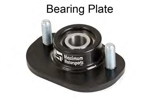
 IMPORTANT: The bearing used in our Caster/Camber Plates is swaged together with Teflon in between the race and ball.")
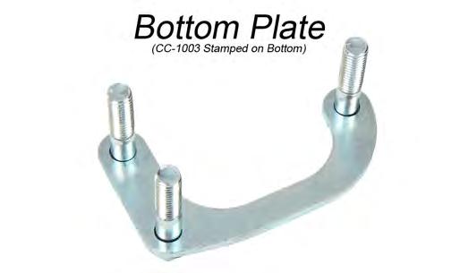
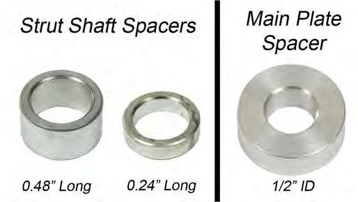
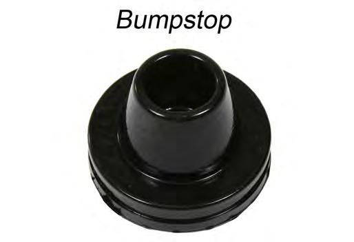
1 3430 Sacramento Dr., Unit D San Luis Obispo, CA Telephone: 805/ Fax: 805/ MM Caster/Camber Plates, (MMCC7989) IMPORTANT: The bearing used in our Caster/Camber Plates is swaged together with Teflon in between the race and ball. This provides a very tight tolerance fit that prevents dirt from entering the bearing. The Teflon reduces friction and minimizes wear over the lifespan of the bearing. The tight tolerances will not allow easy movement of the bearing center by hand. If the center of the bearing must be rotated, use the strut shaft as a lever to facilitate movement. DO NOT ATTEMPT TO LUBRICATE THE BEARING. Any oil or grease will attract dirt and damage the Teflon, voiding the warranty. Read all instructions before beginning work. Following instructions in the proper sequence will ensure the best and easiest installation. Thank you for purchasing Maximum Motorsports Caster/Camber Plates, now with a lifetime warranty against spherical bearing failure and plate failure. That s right If you wear it out, or break it while driving, we will replace that component for free. This warranty applies to the original retail purchaser of all genuine MM Caster/Camber Plates purchased after January of Our Caster/Camber Plates are designed to maximize the performance of your Mustang s front suspension. You will find many features that set our Caster/Camber Plates apart from the rest: The camber adjustment slots in the MM plates, when used in conjunction with the factory camber adjustment slots, allow the widest range of camber adjustment possible. High grade Teflon lined spherical bearings are used at the strut top mounting point. Plates are spaced well above the strut tower top to allow the bump travel to be restored for lowered cars. High grade alloy steel allows our plates to be thin and fatigue proof. MMCC7989r7.indd 1 The latest version, high quality COLOR instructions are available online: Installation Time: 2 hours Supplemental Requirements: When using MM branded struts without a coil-over kit, a Service-6 dust boot kit must be purchased, as the MM struts do not ship with dust boots. Tools Required Standard assortment of hand tools 9/16 socket 3/4 socket Torque wrench 1/8 Drill bit Drill Floor jack and 2 jack stands This Kit Includes 12 1/2 SAE Flat Washer, G8 4 3/8 SAE Flat Washer, G8 4 3/8-16 Nylock Nut 6 1/2-13 Nylock Nut 2 Bumpstop 2 14 Black zip-tie 2 Bearing Plate 2 Bottom Plate 1 Main Plate, Passenger 1 Main Plate, Driver 4 Strut Shaft Spacer, 0.48 Long 4 Strut Shaft Spacer, 0.24 Long 6 1/2 ID Main Plate Spacer Copyright 2010 Maximum Motorsports, Inc.
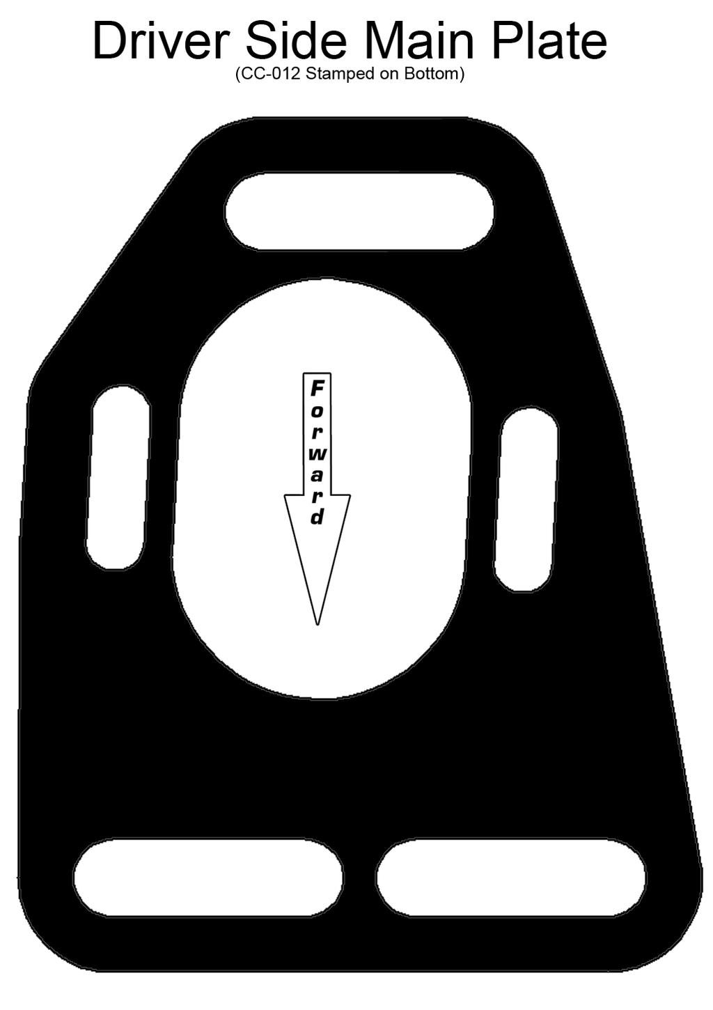
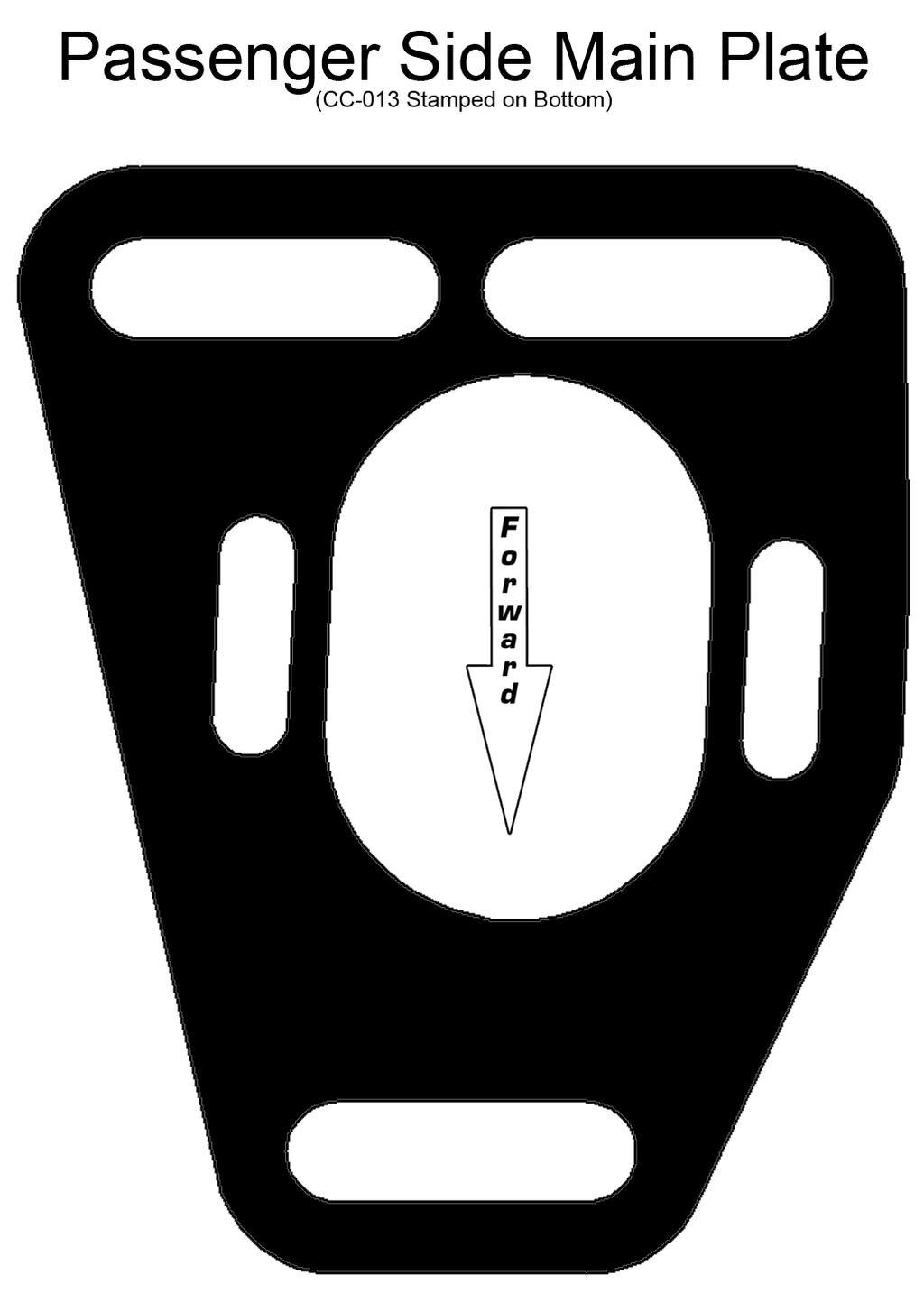
2 Component Identification Copyright 2010 Maximum Motorsports, Inc. 2 MMCC7989r7.indd
3 Factory Strut Mount Removal 1. Jack up front of vehicle and place firmly on jack stands. 2. Remove front wheels. 3. Disconnect the front swaybar endlinks. 4. Place a floor jack under the control arm ball joint and jack up until slightly loaded. 5. Remove the strut shaft retaining nut. If reusing the struts, save the nut, it will be used later. NOTE: It may be easier to initially loosen the nut with air tools. 6. Remove the three nuts that hold the factory strut mount in place. If present, drill and remove the pop rivet that retains the top mounting plate. Discard the top mounting plate. 7. Carefully lower the jack to bring the strut shaft down through the strut tower center hole, but do not completely unload the jack: the spring may become dislodged, causing injury and/or damage. 8. From the top of the strut tower, remove and discard the thrust washer, the top rubber bushing and the crush sleeve from the strut shaft. (Figure 1) 9. Collapse the strut shaft down into the strut body far enough to remove the factory bottom plate and dust boot assembly. Discard the factory bottom plate. Save the dust boot. (Figure 1) NOTE: With some struts, it may be easier to remove the strut from the spindle instead of collapsing the strut shaft into the strut body. 10. Remove and discard the OEM bumpstop from the strut shaft. (Figure 1) 11. Cut and remove the metal band clamp securing the plastic dust boot to the bump cap. Separate the dust boot from the bump cap. Discard the bump cap, but save the dust boot. (Figure 1) MMCC7989r7.indd 3 Copyright 2010 Maximum Motorsports, Inc.
4 MM Camber Plate Installation NOTE: The factory dust boot and provided Bumpstop are NOT used in coil-over applications. Refer to the coil-over installation instructions for more information. 14. Secure the bumpstop to the dust boot with one of the provided zip-ties. (Figure 3) NOTE: If using MM or Bilstein struts, the provided Bumpstops are not used. MM and Bilstein struts have internal bumpstops. NOTE: If using MM struts without a coil-over kit, you must order a Service-6 dust boot replacement kit from Maximum Motorsports. Failure to use a dust boot will void your strut warranty. 12. Attach the provided Bumpstop and dust boot to one another. Slide the assembly over the strut shaft with the conical portion facing upwards. (Figure 2) 15. Identify the driver s side and passenger s side Main Plates. The large center slot will be biased towards the rear of the plates. 16. Install a Bearing Plate onto both Main Plates so that the MM logo faces towards the front of the vehicle. Failure to orient the Bearing Plates correctly will limit your range of adjustment. NOTE: If no sticker is present, the front of the Bearing Plate can be determined as shown below. The bearing is offset rearwards when looking down on the Bearing Plate. (Figure 4) 13. Pull the bumpstop/dust boot assembly down the strut shaft slightly so that it will not interfere with the strut tower while the alignment is being performed. (Figure 3) Copyright 2010 Maximum Motorsports, Inc. 4 MMCC7989r7.indd
5 17. Place a 3/8 washer over each stud of the Bearing Plate, and secure with a 3/8 Nylock nut. Do not tighten the nuts at this time. (Figure 5) 21. Install the appropriate Main Plate/Bearing Plate assembly over the studs of the Bottom Plate on the car. (Figure 8) 22. Install the 1/2 washers and the 1/2 Nylock nuts on the studs of the Bottom Plate. (Figure 8) 18. Install the MM Bottom Plates beneath the strut towers with the 1/2 studs protruding upwards through the factory mounting slots and hole. Make sure the Bottom Plate slides freely in the adjusting slots of the strut tower. If not, file the slots until they do. (Figure 6) 23. Place one 0.48 and one 0.24 Strut Shaft Spacer onto each strut shaft. Compress the strut shaft into the strut body while quickly moving the strut underneath the fender, then let the strut shaft extend up through the Bearing Plate. (Figure 9) NOTE: For MM Coil-over applications, consult your Coil-over Instructions for correct spacer arrangement. NOTE: If your struts are equipped with an adjuster on the top of the shaft, carefully close the hood to check for interference between the top of the strut shaft and the hood. 19. Install 1/2 washers over the 1/2 studs of the Bottom Plate. These washers will rest directly on top of the car s strut tower. (Figure 7) 20. Install the 1/2 ID Main Plate Spacers over the 1/2 studs of the Bottom Plate. (Figure 7) MMCC7989r7.indd 5 Copyright 2010 Maximum Motorsports, Inc.
 IMPORTANT - At least one spacer above the spherical bearing is required to allow proper movement.")
6 24. Place one 0.48 and one 0.24 Strut Shaft Spacer onto each strut shaft, above the spherical bearing. (Figure 10) 25. Reinstall the strut shaft retaining nut and hand tighten. (Figure 10) IMPORTANT - At least one spacer above the spherical bearing is required to allow proper movement. Failure to do so will result in limited bearing articulation and possible damage to the bearing and/or the strut! NOTE: Some aftermarket struts use an English strut shaft diameter that is smaller than the 16mm OEM strut shaft diameter. A cylindrical metal shim should be fabricated and installed between the strut shaft and the spherical bearing to reduce the possibility of movement and noise. NOTE: Various strut manufacturers have unique lengths for the top threaded portion of the strut shaft. You may need to omit a spacer to fully engage the nut on the strut shaft. 27. Reconnect the front swaybar endlinks. 28. Reinstall wheels and carefully lower the vehicle to the ground. 29. Torque the lug nuts to factory specification. 30. Torque the strut shaft retaining nut to your strut manufacturer s specification. Failure to properly torque the nut will allow the strut shaft to move up and down in the bearing, causing damage and various unpleasant noises. 31. The car must now have a proper front-end alignment. While some do-it-yourselfers perform their own alignments at home with the help of a Maximum Motorsports Camber Gauge (Part# MMT-3), many people elect to take their Mustang to a professional alignment shop. On the following page is important information to pass on to the alignment technician. Maximum Motorsports offers the MMT-3 Camber Gauge for about the same cost as a professional alignment. The MMT-3 comes complete with detailed instructions on how to properly measure and adjust caster and camber. 26. Temporarily tighten the caster/camber plate adjusting nuts. 3/8 Nylock: 32 lb-ft 1/2 Nylock: 65 lb-ft Copyright 2010 Maximum Motorsports, Inc. 6 MMCC7989r7.indd
7 3430 Sacramento Dr., Unit D San Luis Obispo, CA Telephone: 805/ Fax: 805/ MM Caster/Camber Plate Alignment Guide, Important Notes for Alignment Do NOT over-torque the adjustment bolts. The proper torque values are: 3/8 Nylock nut (small nut): 32 lb-ft 1/2 Nylock nut (large nut): 65 lb-ft The large center hole of the strut tower can cause interference with the strut shaft when the camber or caster is adjusted towards the limit of travel. If you are adjusting towards the extreme limits of camber and/or caster, check the clearance between the strut shaft and the edge of the large center hole. Check not only with the wheels pointed straight ahead, but also while turning the steering from lock to lock. You may enlarge the center hole with a file or die grinder to provide more clearance. When applicable, the bumpstop must be pulled down, away from the strut tower before setting the alignment. The top of the bumpstop will interfere with the strut tower and limit the adjustment range. Caster and camber settings change the strut shaft s position relative to the hood. Double check hood clearance with the car on the ground, while turning the steering from full lock to full lock. With MM or Bilstein Struts, extra camber adjustment can be gained by loosening the strut to spindle mounting bolts and either pull the strut outwards for less negative camber, or push it inwards for more negative camber. Additional camber adjustment can be achieved by sliding the bottom plates inboard or outboard in the slots on the strut tower. MMCC7989r7.indd 7 Copyright 2010 Maximum Motorsports, Inc.
8 Caster Setting Our recommendation for the caster setting depends on which K-member is used: Caster Setting Street Car ***Race Car*** Stock K-member 3-4 Most Positive MM K-member ***NOTE: Bumpsteer MUST be adjusted when running more than 6 of caster.*** It is typical for alignment shops to set the passenger side caster to a slightly greater amount than the driver side setting. For street-driven cars, a difference of 0.25 to 0.5 will help counter the effect of road crown, and prevent the car from pulling towards the right on most roads. Many variables affect the caster reading. If the car has any rake, the measured amount of caster will be less than if the car was level. Changes in ride height will affect the measured amount of caster. Different technicians using different alignment equipment will indicate different caster values. Unlike camber, the number of degrees that caster is set to does not have to be exact. As long as caster is in the desired range, and the difference from one side to the other is not greater than 0.5, it is fine. Camber Setting Camber Setting Street Car 0.75 negative, +/ Race Car 3.00 negative, varies by track Toe Setting Street Car Race Car Toe Settings 0.5 Total toe-in 0.5 Total toe-out, varies by driver Bumpsteer Bumpsteer is the term for the toe setting of a wheel changing as the suspension moves up and down over bumps, or with body roll while cornering. There is a widespread myth that the tie-rod should be kept parallel to the ground to avoid bumpsteer. THIS IS NOT TRUE! What IS required is for the tierod to be kept parallel to the lower control arm. That way, as the suspension moves, the arc of the ball joint and the arc of the tie-rod end do not transfer any steering input to the spindle. As the car is lowered, the tie-rod end and the lower control arm move together, staying parallel. If offset steering rack bushings are installed on a stock-geometry K-member, the tie-rod end and the lower control arm will no longer be parallel. Installing offset rack bushings will cause a bumpsteer problem. Ford engineers have actually done a very good job at minimizing bumpsteer for a typical street-driven car. Specifically, the bumpsteer was designed to cause the front wheels to toe out during bump. This is a roll understeer condition; the outside loaded tire will turn to the outside of a corner as the body rolls. A car that has a basic tendency towards understeer is more stable and predictable. That predictability makes for a safer street car. Competition cars using stock K-member geometry can benefit by fine-tuning the amount of bumpsteer with an adjustable tie-rod end kit. The MM Adjustable Tie-rod End Kits provide an assortment of spacers, in.015 increments, to help position the tie-rod end at exactly the correct height. Adjusting bumpsteer on a particular Mustang also allows correcting for individual differences in suspension geometry caused by production tolerances. Remember that any time any change is made to the camber setting, the toe setting will be affected, and must be readjusted. It is a good idea to always keep a record of the alignment settings. Inspect the tires frequently for uneven tread wear patterns. If uneven tire wear becomes evident, have the alignment adjusted. With a record of the previous alignment it will be easier to diagnose the problem and make alignment adjustments to improve tire wear. Copyright 2010 Maximum Motorsports, Inc. 8 MMCC7989r7.indd
2. Remove front wheels.
 Read all instructions before beginning work. Following instructions in the proper sequence will ensure the best and easiest installation. Thank you for purchasing Maximum Motorsports Caster/Camber Plates.
US Patent You will find many features that set our Caster/Camber Plates apart from the rest.
 3430 Sacramento Dr., Unit D San Luis Obispo, CA 93401 Telephone: 805/544-8748 Fax: 805/544-8645 www.maximummotorsports.com US Patent 6485223 Read all instructions before beginning work. Following instructions
3430 Sacramento Dr., Unit D San Luis Obispo, CA Telephone: 805/ Fax: 805/
 3430 Sacramento Dr., Unit D San Luis Obispo, CA 93401 Telephone: 805/544-8748 Fax: 805/544-8645 www.maximummotorsports.com MM Caster/Camber Plates, 2005-10 (Mm5CC-1) Read all instructions before beginning
Installation Instructions
 Installation Instructions Eibach Springs, Inc. 264 Mariah Circle Corona, California 92879-1751 USA Tech Support 800-222-8811 Ext 114 CASTER / CAMBER PLATE KIT # 5.3510K 1990-1993 Ford Mustang All FOX Body
Maximum Motorsports Caster/Camber Plates (03-04 Cobra) - Installation Instructions
 - Installation Instructions") Maximum Motorsports Caster/Camber Plates (03-04 Cobra) - Installation Instructions The below installation instructions work for the following products: Maximum Motorsports Caster/Camber Plates (03-04 Cobra)
Maximum Motorsports Caster/Camber Plates (03-04 Cobra) - Installation Instructions The below installation instructions work for the following products: Maximum Motorsports Caster/Camber Plates (03-04 Cobra)
Installation Instructions
 Installation Instructions Eibach Springs, Inc. 264 Mariah Circle Corona, California 92879-1751 USA Tech Support 800-222-8811 Ext 114 CASTER / CAMBER PLATE KIT # 5.3518K 1999-2004 SN95 Ford Mustang - All
MM Caster Camber Plates, (Mm6CC-10)
") 3430 Sacramento Dr., Unit D San Luis Obispo, CA 93401 Telephone: 805/544-8748 Fax: 805/544-8645 www.maximummotorsports.com MM Caster Camber Plates, 2015+ (Mm6CC-10) Read all instructions before beginning
3430 Sacramento Dr., Unit D San Luis Obispo, CA 93401 Telephone: 805/544-8748 Fax: 805/544-8645 www.maximummotorsports.com MM Caster Camber Plates, 2015+ (Mm6CC-10) Read all instructions before beginning
MM Caster/Camber Plates, (Mm5CC-7)
") 3430 Sacramento Dr., Unit D San Luis Obispo, CA 93401 Telephone: 805/544-8748 Fax: 805/544-8645 www.maximummotorsports.com MM Caster/Camber Plates, 2005-14 (Mm5CC-7) Supplemental Installation Notes This
3430 Sacramento Dr., Unit D San Luis Obispo, CA 93401 Telephone: 805/544-8748 Fax: 805/544-8645 www.maximummotorsports.com MM Caster/Camber Plates, 2005-14 (Mm5CC-7) Supplemental Installation Notes This
Adjustable Tie-rod Ends (Mm5TR-1)
") 3430 Sacramento Dr., Unit D San Luis Obispo, CA 93401 Telephone: 805/544-8748 Fax: 805/544-8645 www.maximummotorsports.com 2005-10 Adjustable Tie-rod Ends (Mm5TR-1) 3. Remove the front wheels. 4. Loosen
3430 Sacramento Dr., Unit D San Luis Obispo, CA 93401 Telephone: 805/544-8748 Fax: 805/544-8645 www.maximummotorsports.com 2005-10 Adjustable Tie-rod Ends (Mm5TR-1) 3. Remove the front wheels. 4. Loosen
2011+ Adjustable Tie-rod Ends (Mm5TR-2)
") 3430 Sacramento Dr., Unit D San Luis Obispo, CA 93401 Telephone: 805/544-8748 Fax: 805/544-8645 www.maximummotorsports.com 2011+ Adjustable Tie-rod Ends (Mm5TR-2) Instructions 1. Set the parking brake
3430 Sacramento Dr., Unit D San Luis Obispo, CA 93401 Telephone: 805/544-8748 Fax: 805/544-8645 www.maximummotorsports.com 2011+ Adjustable Tie-rod Ends (Mm5TR-2) Instructions 1. Set the parking brake
Coil-Over Kit, MMD-RC1xxxx Shock (MMCO-23)
") 3430 Sacramento Dr., Unit D San Luis Obispo, CA 93401 Telephone: 805/544-8748 Fax: 805/544-8645 www.maximummotorsports.com Coil-Over Kit, MMD-RC1xxxx Shock (MMCO-23) Supplemental Installation Notes This
3430 Sacramento Dr., Unit D San Luis Obispo, CA 93401 Telephone: 805/544-8748 Fax: 805/544-8645 www.maximummotorsports.com Coil-Over Kit, MMD-RC1xxxx Shock (MMCO-23) Supplemental Installation Notes This
MM Adjustable IRS Tie-Rod (MMIRSTR-2)
") 3430 Sacramento Dr., Unit D San Luis Obispo, CA 93401 Telephone: 805/544-8748 Fax: 805/544-8645 www.maximummotorsports.com MM Adjustable IRS Tie-Rod (MMIRSTR-2) Sample Bumpsteer Curve: Read all instructions
3430 Sacramento Dr., Unit D San Luis Obispo, CA 93401 Telephone: 805/544-8748 Fax: 805/544-8645 www.maximummotorsports.com MM Adjustable IRS Tie-Rod (MMIRSTR-2) Sample Bumpsteer Curve: Read all instructions
Maximum Motorsports Caster/Camber Plates Installation Guide (94-04)
") Maximum Motorsports Caster/Camber Plates Installation Guide (94-04) The below installation instructions work for the following products: Maximum Motorsports Caster/Camber Plates (94-04) Please read through
Maximum Motorsports Caster/Camber Plates Installation Guide (94-04) The below installation instructions work for the following products: Maximum Motorsports Caster/Camber Plates (94-04) Please read through
Front Coil-Over Kit, MMD-FCxxxxx Series (MMCO-24)
") 3430 Sacramento Dr., Unit D San Luis Obispo, CA 93401 Telephone: 805/544-8748 Fax: 805/544-8645 www.maximummotorsports.com Front Coil-Over Kit, MMD-FCxxxxx Series (MMCO-24) Overlooked by other companies,
3430 Sacramento Dr., Unit D San Luis Obispo, CA 93401 Telephone: 805/544-8748 Fax: 805/544-8645 www.maximummotorsports.com Front Coil-Over Kit, MMD-FCxxxxx Series (MMCO-24) Overlooked by other companies,
Coil-Over Kit, MMD-RC1xxxx Shock (MMCO-22)
") 3430 Sacramento Dr., Unit D San Luis Obispo, CA 93401 Telephone: 805/544-8748 Fax: 805/544-8645 www.maximummotorsports.com Coil-Over Kit, MMD-RC1xxxx Shock (MMCO-22) Supplemental Installation Notes This
3430 Sacramento Dr., Unit D San Luis Obispo, CA 93401 Telephone: 805/544-8748 Fax: 805/544-8645 www.maximummotorsports.com Coil-Over Kit, MMD-RC1xxxx Shock (MMCO-22) Supplemental Installation Notes This
MM Tubular K-Member, (Mm5KM-7)
") 3430 Sacramento Dr., Unit D San Luis Obispo, CA 93401 Telephone: 805/544-8748 Fax: 805/544-8645 www.maximummotorsports.com MM Tubular K-Member, 2005-14 (Mm5KM-7) This Kit Contains Congratulations on purchasing
3430 Sacramento Dr., Unit D San Luis Obispo, CA 93401 Telephone: 805/544-8748 Fax: 805/544-8645 www.maximummotorsports.com MM Tubular K-Member, 2005-14 (Mm5KM-7) This Kit Contains Congratulations on purchasing
Coil-Over Kit, MMD-RC0xxxx Shock (MMCO-20)
") 3430 Sacramento Dr., Unit D San Luis Obispo, CA 93401 Telephone: 805/544-8748 Fax: 805/544-8645 www.maximummotorsports.com Coil-Over Kit, MMD-RC0xxxx Shock (MMCO-20) Supplemental Installation Notes OEM
3430 Sacramento Dr., Unit D San Luis Obispo, CA 93401 Telephone: 805/544-8748 Fax: 805/544-8645 www.maximummotorsports.com Coil-Over Kit, MMD-RC0xxxx Shock (MMCO-20) Supplemental Installation Notes OEM
MM Rear Coil-Over Kit - Koni Single and Double Adjustable Shocks (MMCO-5)
") 3430 Sacramento Dr., Unit D San Luis Obispo, CA 93401 Telephone: 805/544-8748 Fax: 805/544-8645 www.maximummotorsports.com MM Rear Coil-Over Kit - Koni Single and Double Adjustable Shocks (MMCO-5) Read
3430 Sacramento Dr., Unit D San Luis Obispo, CA 93401 Telephone: 805/544-8748 Fax: 805/544-8645 www.maximummotorsports.com MM Rear Coil-Over Kit - Koni Single and Double Adjustable Shocks (MMCO-5) Read
Technical Support Line: (952) Fax Line: (952) Hanover Ave. Lakeville, MN
 Fax Line: (952) Hanover Ave. Lakeville, MN") Technical Support Line: (952) 985-5675 Fax Line: (952) 985-5679 21730 Hanover Ave. Lakeville, MN 55044 www.qa1.net INSTALLATION INSTRUCTIONS QA1 P/N CC104MU Camber Caster Plates 1994-2004 Mustang 5.0/4.6
Technical Support Line: (952) 985-5675 Fax Line: (952) 985-5679 21730 Hanover Ave. Lakeville, MN 55044 www.qa1.net INSTALLATION INSTRUCTIONS QA1 P/N CC104MU Camber Caster Plates 1994-2004 Mustang 5.0/4.6
MM IRS Coil-Over Kit - Bilstein/MM Shocks (MMCO-4)
") 3430 Sacramento Dr., Unit D San Luis Obispo, CA 93401 Telephone: 805/544-8748 Fax: 805/544-8645 www.maximummotorsports.com MM IRS Coil-Over Kit - Bilstein/MM Shocks (MMCO-4) The lower spring perch is drilled
3430 Sacramento Dr., Unit D San Luis Obispo, CA 93401 Telephone: 805/544-8748 Fax: 805/544-8645 www.maximummotorsports.com MM IRS Coil-Over Kit - Bilstein/MM Shocks (MMCO-4) The lower spring perch is drilled
J&M CASTER/CAMBER PLATE INSTALLATION INSTRUCTIONS (#24213) Hardware:
 Hardware:") J&M CASTER/CAMBER PLATE INSTALLATION INSTRUCTIONS (#24213) Thank you for purchasing J&M Product s Caster/Camber Plates (#24213) for 1994-2004 Ford Mustang. The J&M Caster/Camber plates are the highest
J&M CASTER/CAMBER PLATE INSTALLATION INSTRUCTIONS (#24213) Thank you for purchasing J&M Product s Caster/Camber Plates (#24213) for 1994-2004 Ford Mustang. The J&M Caster/Camber plates are the highest
MM Rear Coil-Over Kit - Bilstein Shocks (MMCO-3)
") 3430 Sacramento Dr., Unit D San Luis Obispo, CA 93401 Telephone: 805/544-8748 Fax: 805/544-8645 www.maximummotorsports.com MM Rear Coil-Over Kit - Bilstein Shocks (MMCO-3) Read all instructions before
3430 Sacramento Dr., Unit D San Luis Obispo, CA 93401 Telephone: 805/544-8748 Fax: 805/544-8645 www.maximummotorsports.com MM Rear Coil-Over Kit - Bilstein Shocks (MMCO-3) Read all instructions before
Maximum Motorsports Camber Caster Plates (05-10):
:") Maximum Motorsports Camber Caster Plates (05-10): Tools Required: Lug Wrench 21mm Deep Socket 18mm Deep Socket 15mm Deep Socket 17mm Socket 13mm Socket 10mm Socket Torque Wrench (requires 166lb-ft capacity
Maximum Motorsports Camber Caster Plates (05-10): Tools Required: Lug Wrench 21mm Deep Socket 18mm Deep Socket 15mm Deep Socket 17mm Socket 13mm Socket 10mm Socket Torque Wrench (requires 166lb-ft capacity
MM K-Member, chassis w/4.6l engine & Hellion Turbo Kit (MMKM-3.1)
") 3430 Sacramento Dr., Unit D San Luis Obispo, CA 93401 Telephone: 805/544-8748 Fax: 805/544-8645 www.maximummotorsports.com MM K-Member, 1979-95 chassis w/4.6l engine & Hellion Turbo Kit (MMKM-3.1) Proper
3430 Sacramento Dr., Unit D San Luis Obispo, CA 93401 Telephone: 805/544-8748 Fax: 805/544-8645 www.maximummotorsports.com MM K-Member, 1979-95 chassis w/4.6l engine & Hellion Turbo Kit (MMKM-3.1) Proper
MM K-Member, chassis with 4.6 engine (MMKM-2.1)
") 3430 Sacramento Dr., Unit D San Luis Obispo, CA 93401 Telephone: 805/544-8748 Fax: 805/544-8645 www.maximummotorsports.com MM K-Member, 1979-95 chassis with 4.6 engine (MMKM-2.1) most rigid, and yet our
3430 Sacramento Dr., Unit D San Luis Obispo, CA 93401 Telephone: 805/544-8748 Fax: 805/544-8645 www.maximummotorsports.com MM K-Member, 1979-95 chassis with 4.6 engine (MMKM-2.1) most rigid, and yet our
2005-Pres. Ford Mustang Camber Plate Installation Instructions:
 2005-Pres. Ford Mustang Camber Plate Installation Instructions: J&M Products once again outdoes our competitors with these fully adjustable PATENT PENDING Camber & Caster plate assemblies for the 2005-2010
MM Heavy Duty Torque-arm (MMTA-3 & -4) Engine Torque Table 4.56: : :
 Engine Torque Table 4.56: : :") 3430 Sacramento Dr., Unit D San Luis Obispo, CA 93401 Telephone: 805/544-8748 Orders Only: 800/839-0928 Fax: 805/544-8645 The ultimate rear suspension for your Mustang is now available from Maximum Motorsports.
3430 Sacramento Dr., Unit D San Luis Obispo, CA 93401 Telephone: 805/544-8748 Orders Only: 800/839-0928 Fax: 805/544-8645 The ultimate rear suspension for your Mustang is now available from Maximum Motorsports.
MM Brake Hose Kit (MMBK13R)
") 3430 Sacramento Dr., Unit D San Luis Obispo, CA 93401 Telephone: 805/544-8748 Fax: 805/544-8645 www.maximummotorsports.com MM Brake Hose Kit (MMBK13R) Read all instructions before beginning work. Following
3430 Sacramento Dr., Unit D San Luis Obispo, CA 93401 Telephone: 805/544-8748 Fax: 805/544-8645 www.maximummotorsports.com MM Brake Hose Kit (MMBK13R) Read all instructions before beginning work. Following
MM Panhard Bar, Mustang (MMPBA)
") 3430 Sacramento Dr., Unit D San Luis Obispo, CA 93401 Telephone: 805/544-8748 Fax: 805/544-8645 www.maximummotorsports.com MM Panhard Bar, 1979-98 Mustang (MMPBA) Important Note for Customers with Baer
3430 Sacramento Dr., Unit D San Luis Obispo, CA 93401 Telephone: 805/544-8748 Fax: 805/544-8645 www.maximummotorsports.com MM Panhard Bar, 1979-98 Mustang (MMPBA) Important Note for Customers with Baer
MM Brake Line Kit (MMBK14R)
") 3430 Sacramento Dr., Unit D San Luis Obispo, CA 93401 Telephone: 805/544-8748 Fax: 805/544-8645 www.maximummotorsports.com MM Brake Line Kit (MMBK14R) Read all instructions before beginning work. Following
3430 Sacramento Dr., Unit D San Luis Obispo, CA 93401 Telephone: 805/544-8748 Fax: 805/544-8645 www.maximummotorsports.com MM Brake Line Kit (MMBK14R) Read all instructions before beginning work. Following
MM Brake Line Kit for Fox-IRS Swap (MMBAK-21)
") 3430 Sacramento Dr., Unit D San Luis Obispo, CA 93401 Telephone: 805/544-8748 Fax: 805/544-8645 www.maximummotorsports.com MM Brake Line Kit for Fox-IRS Swap (MMBAK-21) Supplemental Installation Notes
3430 Sacramento Dr., Unit D San Luis Obispo, CA 93401 Telephone: 805/544-8748 Fax: 805/544-8645 www.maximummotorsports.com MM Brake Line Kit for Fox-IRS Swap (MMBAK-21) Supplemental Installation Notes
Global West Suspension 655 South Lincoln Ave San Bernardino Ca Phone Fax Web address globalwest.
 Global West Suspension 655 South Lincoln Ave San Bernardino Ca. 92408 Phone 877-470-2975 Fax 909-890-0703 Web address globalwest.net Mustang coilover instruction sheets for 64-66 Kit includes the following
4.6L Oil Filter Relocation Kit, (OC-7)
") 3430 Sacramento Dr., Unit D San Luis Obispo, CA 93401 Telephone: 805/544-8748 Fax: 805/544-8645 www.maximummotorsports.com 4.6L Oil Filter Relocation Kit, 2003-04 (OC-7) Filter Mount Installation 4. Remove
3430 Sacramento Dr., Unit D San Luis Obispo, CA 93401 Telephone: 805/544-8748 Fax: 805/544-8645 www.maximummotorsports.com 4.6L Oil Filter Relocation Kit, 2003-04 (OC-7) Filter Mount Installation 4. Remove
Part # Camber Caster Plates Ford Mustang All Ford Mustang GT500
 Part # 24220 Camber Caster Plates 2005-2010 Ford Mustang All 2007-2014 Ford Mustang GT500 J&M Products once again outdoes our competitors with these fully adjustable (Protected under US Patent No. 8,820,759
MM K-Member, chassis with 5.0L engine (MMKM-1.1)
") 3430 Sacramento Dr., Unit D San Luis Obispo, CA 93401 Telephone: 805/544-8748 Fax: 805/544-8645 www.maximummotorsports.com Read all instructions before beginning work. Following instructions in the proper
3430 Sacramento Dr., Unit D San Luis Obispo, CA 93401 Telephone: 805/544-8748 Fax: 805/544-8645 www.maximummotorsports.com Read all instructions before beginning work. Following instructions in the proper
Hybrid Steering Shaft, SN95 Rack in Fox Chassis (MMST-13)
") 3430 Sacramento Dr., Unit D San Luis Obispo, CA 93401 Telephone: 805/544-8748 Fax: 805/544-8645 www.maximummotorsports.com Hybrid Steering Shaft, SN95 Rack in Fox Chassis (MMST-13) Improving Performance
3430 Sacramento Dr., Unit D San Luis Obispo, CA 93401 Telephone: 805/544-8748 Fax: 805/544-8645 www.maximummotorsports.com Hybrid Steering Shaft, SN95 Rack in Fox Chassis (MMST-13) Improving Performance
Standard Duty Oil Filter Relocation Kit (OC-8)
") 3430 Sacramento Dr., Unit D San Luis Obispo, CA 93401 Telephone: 805/544-8748 Fax: 805/544-8645 www.maximummotorsports.com Standard Duty Oil Filter Relocation Kit (OC-8) Filter Mount Installation 4. Remove
3430 Sacramento Dr., Unit D San Luis Obispo, CA 93401 Telephone: 805/544-8748 Fax: 805/544-8645 www.maximummotorsports.com Standard Duty Oil Filter Relocation Kit (OC-8) Filter Mount Installation 4. Remove
IRS Racing Brake Kit (MMBAK-15, -16)
") 3430 Sacramento Dr., Unit D San Luis Obispo, CA 93401 Telephone: 805/544-8748 Fax: 805/544-8645 www.maximummotorsports.com IRS Racing Brake Kit (MMBAK-15, -16) Floating rotors (MMBAK-16 ONLY) can move
3430 Sacramento Dr., Unit D San Luis Obispo, CA 93401 Telephone: 805/544-8748 Fax: 805/544-8645 www.maximummotorsports.com IRS Racing Brake Kit (MMBAK-15, -16) Floating rotors (MMBAK-16 ONLY) can move
Steeda S550 Mustang Front Coilover Installation Instructions For Part:
 Steeda S550 Mustang Front Coilover Installation Instructions For Part: 555-8170 Tools required 1. Jack 2. Jack stands 3. Torque Wrench 4. 10mm wrench 5. 11mm wrench 6. 17mm wrench 7. 18mm socket 8. Plastic
Chrysler A-Body Tubular A-Arms Installation Instructions A-ARM INSTALLATION
 1967-1976 Dodge Demon 1112 67-72 Chrysler A-Body Tubular A-Arms Installation Instructions Thank you for your purchase of this Hotchkis Performance product. Your A-Arm set was designed with the performance
07-UP AVALANCHE 7.5 KIT
 92120900R1 07-UP AVALANCHE 7.5 KIT Thank you for choosing Rough Country for your suspension needs. We appreciate your business!! This kit will not fit vehicles equipped with electric steering or trucks
Camaro Camber Kit Installation
 Camaro Camber Kit Installation Part Name: Camaro Camber Kit Part Number: 1410120/1410111 Application: 2010 + Chevrolet Camaro V8 and V6 Level of Difficulty: Moderate Expected Installation Time: 2 Hours
2.5" & 3.5" SUSPENSION SYSTEM 2018 JEEP JL WRANGLER 4 DOOR MODELS
 2.5" & 3.5" SUSPENSION SYSTEM 2018 JEEP JL WRANGLER 4 DOOR MODELS JSPEC1202/JSPEC1203 www.jksmfg.com jks@sporttruckusainc.com 517-278-1226 RV. 050318 GETTING STARTED Read all warnings, instructions, notes
2005+ Roll Bar (Mm5RB-20.1 to -20.6) Recommended Center punch 1/8" pilot drill 1-3/4" Hole saw 2" Hole saw
 Recommended Center punch 1/8 pilot drill 1-3/4 Hole saw 2 Hole saw") 3430 Sacramento Dr., Unit D San Luis Obispo, CA 93401 Telephone: 805/544-8748 Fax: 805/544-8645 www.maximummotorsports.com 2005+ Roll Bar (Mm5RB-20.1 to -20.6) Recommended Center punch 1/8" pilot drill
3430 Sacramento Dr., Unit D San Luis Obispo, CA 93401 Telephone: 805/544-8748 Fax: 805/544-8645 www.maximummotorsports.com 2005+ Roll Bar (Mm5RB-20.1 to -20.6) Recommended Center punch 1/8" pilot drill
2.5" & 3.5" SUSPENSION SYSTEM JEEP JK WRANGLER 2 & 4 DOOR MODELS
 2.5" & 3.5" SUSPENSION SYSTEM 2007-2018 JEEP JK WRANGLER 2 & 4 DOOR MODELS JSPEC2352 www.jksmfg.com jks@ridefox.com 517-278-1226 RV. 100818 GETTING STARTED Read all warnings, instructions, notes and cautions
Ford AOD-4R70W-AODE Cable Operated Shifter Installation Instructions
 Ford AOD-4R70W-AODE Cable Operated Shifter Installation Instructions Building American Quality With A Lifetime Warranty! TOLL FREE 1-877-469-7440 tech@lokar.com www.lokar.com Ford AOD-4R70W-AODE Cable
INSTALLATION INSTRUCTIONS QA1 P/N x400, x500, x600, x400, x500, x F100 Front Coil-over Suspension System
 INSTALLATION INSTRUCTIONS QA1 P/N 52620-x400, 52620-x500, 52620-x600, 52621-x400, 52621-x500, 52621-x600 65-72 F100 Front Coil-over Suspension System TOOLS AND SUPPLIES REQUIRED Floor Jack Two (2) Jack
JEEP JK 4 LONGARM. Tools Needed: Thank you for choosing Rough Country for your suspension needs.
 921786000 Thank you for choosing Rough Country for your suspension needs. JEEP JK 4 LONGARM Rough Country recommends a certified technician install this system. In addition to these instructions, professional
AEV30213AH Last Updated: 04/28/17. jk wrangler dualsport sc suspension INSTALLATION GUIDE
 AEV30213AH Last Updated: 04/28/17 jk wrangler 3.5 4.5 dualsport sc suspension INSTALLATION GUIDE PLEASE READ BEFORE YOU START TO GUARANTEE A QUALITY INSTALLATION, WE RECOMMEND READING THESE INSTRUCTIONS
Cobra IRS Aluminum Differential Bushings (MMIRSB-40.2)
") 3430 Sacramento Dr., Unit D San Luis Obispo, CA 93401 Telephone: 805/544-8748 Fax: 805/544-8645 www.maximummotorsports.com Cobra IRS Aluminum Differential Bushings (MMIRSB-40.2) The MM front differential
3430 Sacramento Dr., Unit D San Luis Obispo, CA 93401 Telephone: 805/544-8748 Fax: 805/544-8645 www.maximummotorsports.com Cobra IRS Aluminum Differential Bushings (MMIRSB-40.2) The MM front differential
GR40 SLA Installation and Set Up Instructions.
 GR40 SLA Installation and Set Up Instructions. Read these instructions completely before beginning. These instructions are written for experienced installer/technicians with a strong idea as to how a chassis
PPM-8022 / PPM-8042 JEEP JK STAGE 2 SYNERGY SUSPENSION SYSTEM Version 1
 POLY PERFORMANCE MFG. 870 INDUSTRIAL WAY, SAN LUIS OBISPO, CA (805) 242-0397 PPM-8022 / PPM-8042 JEEP JK STAGE 2 SYNERGY SUSPENSION SYSTEM Version 1 GENERAL NOTES: These instructions are also available
PPM-8023 / PPM-8043 JEEP JK SYNERGY STAGE 3 SUSPENSION SYSTEM Version 1
 SYNERGY MFG. 870 INDUSTRIAL WAY, SAN LUIS OBISPO, CA (805) 242-0397 PPM-8023 / PPM-8043 JEEP JK SYNERGY STAGE 3 SUSPENSION SYSTEM Version 1 GENERAL NOTES: These instructions are also available on our website;
Ford AOD-4R70W-AODE Cable Operated Shifter Installation Instructions
 Ford AOD-4R70W-AODE Cable Operated Shifter Installation Instructions Building American Quality With A Lifetime Warranty! TOLL FREE 1-877-469-7440 tech@lokar.com www.lokar.com Ford AOD-4R70W-AODE Cable
INSTALLATION INSTRUCTIONS
 INSTALLATION INSTRUCTIONS 2005-2012 Nissan Xterra/Frontier / Pathfinder PART NUMBERS: NP17500, NP17525, NP17550 FRONTIER PARTS & CORRESPONDING HARDWARE LIST XTERRA PATHFINDER ABOVE LISTED 1/2 Metal Lock
Suspension System RS6582B
 Suspension System RS6582B Tahoe/Yukon READ ALL INSTRUCTIONS THOROUGHLY FROM START TO FINISH BEFORE BEGINNING INSTALLATION IMPORTANT NOTES! WARNING: This suspension system will enhance the off-road performance
Trucks with a mass damper on the front diff, the damper will have to be removed.
 922912000B *1291BAG6* 1291BAG6 Thank you for choosing Rough Country for your suspension needs. Rough Country recommends a certified technician install this system. In addition to these instructions, professional
Tools Needed: Class 8.8 Class MM 55ft/lbs 75ft/lbs 14MM 85ft/lbs 120ft/lbs 16MM 130ft/lbs 165ft/lbs 18MM 170ft/lbs 240ft/lbs
 921788000 JEEP JK 6 LONGARM Rough Country recommends a certified technician install this system. In addition to these instructions, professional knowledge of disassemble/reassembly procedures as well as
Severe Duty Oil Filter Relocation Kit (OC-9)
") 3430 Sacramento Dr., Unit D San Luis Obispo, CA 93401 Telephone: 805/544-8748 Fax: 805/544-8645 www.maximummotorsports.com Severe Duty Oil Filter Relocation Kit (OC-9) Filter Mount Installation 4. Remove
3430 Sacramento Dr., Unit D San Luis Obispo, CA 93401 Telephone: 805/544-8748 Fax: 805/544-8645 www.maximummotorsports.com Severe Duty Oil Filter Relocation Kit (OC-9) Filter Mount Installation 4. Remove
Installation Procedure GR40 S197 SLA Front Suspension System (Does not include Aluminum Spindle and Hub Instructions)
") Installation Procedure GR40 S197 SLA Front Suspension System (Does not include Aluminum Spindle and Hub Instructions) Please take the time and read these instructions first! The GR40 S197 system is designed
Installation Procedure GR40 S197 SLA Front Suspension System (Does not include Aluminum Spindle and Hub Instructions) Please take the time and read these instructions first! The GR40 S197 system is designed
INSTALLATION INSTRUCTIONS 88029
 INSTALLATION INSTRUCTIONS 88029 FOR SUSPENSION SYSTEMS RS6503: JEEP WRANGLER (TJ) READ ALL INSTRUCTIONS THOROUGHLY FROM START TO FINISH BEFORE BEGINNING INSTALLATION REV F IMPORTANT NOTES! WARNING: This
INSTALLATION GUIDE. TCP TIER-14 Bump Steer Conversion Kit - Early Mustang to Late Spindle
 READ ALL INSTRUCTIONS COMPLETELY AND THOROUGHLY UNDERSTAND THEM BEFORE DOING ANYTHING. CALL TOTAL CONTROL PRODUCTS TECH SUPPORT (916) 388-0288 IF YOU NEED ASSISTANCE. INSTALLATION GUIDE TCP TIER-14 Bump
Standard Duty Oil Filter Relocation Kit (OC-3)
") 3430 Sacramento Dr., Unit D San Luis Obispo, CA 93401 Telephone: 805/544-8748 Fax: 805/544-8645 www.maximummotorsports.com Standard Duty Oil Filter Relocation Kit (OC-3) Read all of the instructions before
3430 Sacramento Dr., Unit D San Luis Obispo, CA 93401 Telephone: 805/544-8748 Fax: 805/544-8645 www.maximummotorsports.com Standard Duty Oil Filter Relocation Kit (OC-3) Read all of the instructions before
M-Force E36 Camber Plate Installation
 Thank you for purchasing the Adjustable Camber Plate kit from Vorshlag Motorsports. In order to ensure proper installation and longevity of your kit, Vorshlag Motorsports recommends that you have your
Manual Brake Conversion Kit, (MMBAK-13)
") 3430 Sacramento Dr., Unit D San Luis Obispo, CA 93401 Telephone: 805/544-8748 Fax: 805/544-8645 www.maximummotorsports.com Manual Brake Conversion Kit, 1994-95 (MMBAK-13) The MM kit includes a CNC machined
3430 Sacramento Dr., Unit D San Luis Obispo, CA 93401 Telephone: 805/544-8748 Fax: 805/544-8645 www.maximummotorsports.com Manual Brake Conversion Kit, 1994-95 (MMBAK-13) The MM kit includes a CNC machined
»Product» Safety Warning
 C2402, C2602 Installation Instructions 2007-2013 Chevy 1/2 Ton 2wd Pickup 4.5", 6.5" Suspension System Read and understand all instructions and warnings prior to installation of product and operation of
Detroit Speed, Inc. Front Coilover Kit Race Double Adjustable Camaro P/N:
 Detroit Speed, Inc. Front Coilover Kit Race Double Adjustable 2010+ Camaro P/N: 030321 Item Quantity Description 1 2 Front Strut Assembly (Double Adjustable) 2 2 Coilover Spring 250# x 2.5"ID x 8"L 3 2
Steeda Bumpsteer Kit (94-04) - Installation Instructions
 - Installation Instructions") Steeda Bumpsteer Kit (94-04) - Installation Instructions The below installation instructions work for the following products: Steeda Bumpsteer Kit (94-04) Please read through the instructions carefully
Steeda Bumpsteer Kit (94-04) - Installation Instructions The below installation instructions work for the following products: Steeda Bumpsteer Kit (94-04) Please read through the instructions carefully
JEEP JK 4 SUSPENSION KIT
 92168100 Thank you for choosing Rough Country for your suspension needs. JEEP JK 4 SUSPENSION KIT Rough Country recommends a certified technician install this system. In addition to these instructions,
INSTALLATION GUIDE TCP SPND MUSTANG SPINDLES WITH GRANADA OUTER TIE-ROD TAPER
 READ ALL INSTRUCTIONS COMPLETELY AND THOROUGHLY UNDERSTAND THEM BEFORE DOING ANYTHING. CALL TOTAL CONTROL PRODUCTS TECH SUPPORT (916) 388-0288 IF YOU NEED ASSISTANCE. INSTALLATION GUIDE TCP SPND-04 70-73
INSTALLATION INSTRUCTION 88146
 INSTALLATION INSTRUCTION 88146 Rev H FOR RANCHO SUSPENSION SYSTEM RS6547: 4WD SUBURBAN/YUKON XL, 4WD TAHOE/YUKON, & 4WD AVALANCHE READ ALL INSTRUCTIONS THOROUGHLY FROM START TO FINISH BEFORE BEGINNING
IMPORTANT! READ THIS FIRST!
 IMPORTANT! READ THIS FIRST! Installation of shock absorbers requires special tools and expert knowledge. Accordingly, installation of all BILSTEIN products must be performed by a qualified suspension specialist.
Drag Race Roll Bar (MMRB-6, -7)
") 3430 Sacramento Dr., Unit D San Luis Obispo, CA 93401 Telephone: 805/544-8748 Fax: 805/544-8645 www.maximummotorsports.com 1994-04 Drag Race Roll Bar (MMRB-6, -7) The Maximum Motorsports 6-point Drag Race
3430 Sacramento Dr., Unit D San Luis Obispo, CA 93401 Telephone: 805/544-8748 Fax: 805/544-8645 www.maximummotorsports.com 1994-04 Drag Race Roll Bar (MMRB-6, -7) The Maximum Motorsports 6-point Drag Race
04-08 FORD F150 4 KIT
 9257700 04-08 FORD F50 4 KIT THANK YOU FOR CHOOSING ROUGH COUNTRY FOR YOUR SUSPENSION NEEDS. Rough Country recommends a certified technician install this system. In addition to these instructions, professional
Installation Instructions. 6 Basic System FTS21060BK / FTS21061BK / FTS21042BK GM 2WD C1500 P/U ONLY
 Installation Instructions 6 Basic System FTS21060BK / FTS21061BK / FTS21042BK 2007-13 GM 2WD C1500 P/U ONLY 2007-13 GM 1500 Truck Basic System FTS21060BK / FTS21061BK / FTS21042BK 2007-13 GM 2WD C1500
Ford C4 and C6 Floor Mount Automatic Transmission Shifter Installation Instructions
 Ford C4 and C6 Mount Automatic Transmission Shifter Installation Instructions Building American Quality With A Lifetime Warranty! TOLL FREE 1-877-469-7440 tech@lokar.com www.lokar.com Ford C4 and C6 Mount
Installation Instructions
 Installation Instructions 6 Suspension System FTS25005BK / FTS25006BK 2006-2012 Nissan Frontier 2wd/4wd SHORT BED ONLY Tool List: (not included) Floor Jack & Jack Stands Assorted Metric & S.A.E Sockets
INSTRUCTION S G-Comp Front Suspension: Chevy Nova Speedway Motors, Inc. 2017
 INSTRUCTION S 350-100 G-Comp Front Suspension: 62-67 Chevy Nova Speedway Motors, Inc. 2017 Kit Contents: 91035700 G-Comp Bare Subframe 350101 G-Comp Support Tubes 91035702 G-Comp Front Subframe Hardware
GM 2016-UP wd 3.5 Stamped Steel & Aluminum LCA Knuckle Lift Kit
 921121300B *12130BAG4* 12130BAG4 GM 2016-UP 1500 4wd 3.5 Stamped Steel & Aluminum LCA Knuckle Lift Kit Thank you for choosing Rough Country for your suspension needs. Rough Country recommends a certified
NISSAN TITAN XD NISSAN TITAN (LD) PATENTED
 PATENTED") PRORYDE ADJUSTABLE FRONT LIFT KIT INSTALLATION 2016 + NISSAN TITAN XD 2017 + NISSAN TITAN (LD) PATENTED IMPORTANT! Read ALL WARNINGS and information contained in these instructions PRIOR to installing
PRORYDE ADJUSTABLE FRONT LIFT KIT INSTALLATION 2016 + NISSAN TITAN XD 2017 + NISSAN TITAN (LD) PATENTED IMPORTANT! Read ALL WARNINGS and information contained in these instructions PRIOR to installing
CSS-C SUSPENSION LIFT KIT
 115 W. La Cadena Dr. Ste 100 Riverside, CA 92501 (951) 328-9902 phone (951) 328-9908 fax 2000-2006 CHEVROLET SILVERADO 1500 4WD CSS-C3-2 6-8 SUSPENSION LIFT KIT WARNING: CALIFORNIA SUPERTRUCKS RECOMMENDS
INSTRUCTION S G-Comp Front Suspension: Chevy Camaro Speedway Motors, Inc Kit Contents:
 INSTRUCTION S 350-500 G-Comp Front Suspension: 70-81 Chevy Camaro Speedway Motors, Inc. 2017 Kit Contents: 350500.1 G-Comp Subframe, Camaro 350500.2 G-Comp Sway Bar Kit, Camaro 350500.3 Hardware Kit, G-Comp
1. General Description
 General Description 1. General Description A: SPECIFICATION Front Rear Model Wheel arch height (Tolerance: +12 mm 24 mm ( +0.47 in 0.94 in)) mm (in) 376 (14.8) Camber (Tolerance: 0 45 Differences between
IMPORTANT! PLEASE READ ALL INSTRUCTIONS FIRST!
 MOUNTNG NSTRUCTON MPORTANT! PLEASE READ ALL NSTRUCTONS FRST! f in doubt, please contact your local BLSTEN dealer or our sales department before installation. When replacing other brands, BLSTEN shock absorbers
09-12 Dodge 4WD Leveling Kit
 9235900 09-12 Dodge 4WD 1500 2.5 Leveling Kit Thank you for choosing Rough Country for all your suspension needs. DOES NOT FIT TRX PACKAGE VEHICLES!! Rough Country recommends a certified technician install
60-65 Falcon, Comet & Ranchero Coil Spring IFS
 60-65 Falcon, 62-65 Comet & 62-65 Ranchero Coil Spring IFS All engine installations with this front end will require a rear sump oil pan. 289-302 Small Block Ford Motors Milodon rear sump pan holds 7 quarts
Powerglide Automatic Floor Mount Shifter Installation Instructions
 Powerglide Automatic Mount Installation Instructions Building American Quality With A Lifetime Warranty! TOLL FREE 1-877-469-7440 (865) 966-2269 FAX (865) 671-1999 tech@lokar.com www.lokar.com Powerglide
2013-UP 3500 Dodge 5 Lift Kit SRW
 92369200 2013-UP 3500 Dodge 5 Lift Kit SRW Thank you for choosing Rough Country Suspension for your Off Road needs. Rough Country recommends a certified technician installs this system. In addition to
97-06 JEEP TJ/LJ LONG ARM UPGRADE KIT
 921663U00 97-06 JEEP TJ/LJ LONG ARM UPGRADE KIT Thank you for choosing Rough Country for your suspension needs. This kit is an upgrade kit only. This kit includes frame mounting points and adjustable long
»Product» Safety Warning
 #F1420 Installation Instructions 2011 Ford Super Duty F250/350 4wd 4" Suspension Lift Read and understand all instructions and warnings prior to installation of product and operation of vehicle. Zone Offroad
Instruction set # 7068 Cognito Motorsports, Inc. Upper Control Arm Leveling Kit for GM 8-Lug #UCAK (Boxed Style)
") Cognito Motorsports, Inc. Upper Control Arm Leveling Kit for 2001-2010 GM 8-Lug #UCAK100010 (Boxed Style) Introduction - These control arms will not affect the height of the truck, the height is determined
Cognito Motorsports, Inc. Upper Control Arm Leveling Kit for 2001-2010 GM 8-Lug #UCAK100010 (Boxed Style) Introduction - These control arms will not affect the height of the truck, the height is determined
STaSIS Engineering B6 B7 Streetsport Suspension
 STaSIS Engineering B6 B7 Streetsport Suspension SS Suspension Kit Parts List Qty Description Part Number 1 STaSIS adjusted Koni cadmium plated dampers (2 front, 2 rear) 1150-5061 Special Tools Required
PRODUCT USE INFORMATION
 921545200 *54520BAG1* 54520BAG1 Thank you for choosing Rough Country for all your suspension needs. 2009-17 Ford F150 3 Suspension Kit Rough Country recommends a certified technician install this system.
Installations Instructions for Maier Racing Front Coilover Kit MS Ford Mustang
 22215 Meekland Avenue Hayward, CA 94541 Phone: (510) 581-7600 Fax: (510) 581-2406 Installations Instructions for Maier Racing Front Coilover Kit MS-02-001 1964-1973 Ford Mustang Contents Front Coilover
2.5" & 3.5" SUSPENSION SYSTEM
 2.5" & 3.5" SUSPENSION SYSTEM 2007-2014 JEEP JK WRANGLER 2 & 4 DOOR MODELS JSPEC2352 www.jksmfg.com jks@sporttruckusainc.com 517-278-1226 Rv. 071814 Getting Started Read all warnings, instructions, notes
Tacoma Front Suspension Install Instructions
 1995-04 Tacoma Front Suspension Install Instructions Important notices: These instructions are intended only as a general guide for installing All-Pro products. For some items, specialized mechanical skills,
07 & UP 4WD GM FRT 1.5 REAR LIFT KIT
 92126900 Thank you for choosing Rough Country for your suspension needs. Rough Country recommends a certified technician install this system. In addition to these instructions, professional knowledge of
FRONT & 4 REAR GM WD LOWERING KIT
 92725200 88-98 2 FRONT & 4 REAR GM 1500 2WD LOWERING KIT Thank you for choosing Rough Country for all your suspension needs. Rough Country recommends a certified technician install this system. In addition
E4-WM5-Y530A00 MOUNTING INSTRUCTION
 IMPORTANT! READ THIS FIRST! Installation of shock absorbers requires special tools and expert knowledge. Accordingly, installation of all BILSTEIN products must be performed by a qualified suspension specialist.
PRODUCT USE INFORMATION
 Toyota 2007-17 Tundra 3.5 4wd/2wd Suspension Kit Thank you for choosing Rough Country for all your suspension needs. 9217682000A *76820BAG4* 76820BAG4 Rough Country recommends a certified technician install