Limit Switches according to EN 50041
|
|
|
- Stewart George
- 5 years ago
- Views:
Transcription


1 Limit Switches according to EN 5 More than safety.


2 utomation More than safety. Emil Euchner, the company s founder and inventor of the multiple limit switch, circa 98. round the world the Swabian specialists in motion sequence control for mechanical and systems engineering. EUCHNER s history began in 9 with the establishment of an engineering office by Emil Euchner. Since that time, EUCHNER has been involved in the design and development of switchgear for controlling a wide variety of motion sequences in mechanical and systems engineering. In 95, Emil Euchner founded EUCHNER + Co., a milestone in the company s history. In 95, he developed the first multiple limit switch to this day a symbol of the enterprising spirit of this familyowned company. utomation Safety ManMachine Today, our products range from electromechanical and electronic components to complex system solutions. With this wide range of products we can provide the necessary technologies to offer the right solution for special requirements regardless of whether these relate to reliable and precise positioning or to components and systems for safety engineering in the automation sector. EUCHNER products are sold through a world-wide sales network of competent partners. With our closeness to the customer and the guarantee of reliable solutions throughout the globe, we enjoy the confidence of customers all over the world. Quality, reliability, precision Quality, reliability and precision are the hallmarks of our corporate philosophy. They represent concepts and values to which we feel totally coitted. t EUCHNER, quality means that all our employees take personal responsibility for the company as a whole and, in particular, for their own field of work. This individual coitment to perfection results in products which are ideally tailored to the customers needs and the requirements of the market. fter all: our customers and their needs are the focus of all our efforts. Through efficient and effective use of resources, the promotion of personal initiative and courage in finding unusual solutions to the benefit of our customers, we ensure a high level of customer satisfaction. We familiarize ourselves with their needs, requirements and products and we learn from the experiences of our customers own customers. EUCHNER More than safety. Quality made by EUCHNER

3 Table of contents Limit switches according to EN 5 Introduction dvantages and features 5 Typical applications The limit switch in detail 7 djustment options 8 Switching elements 9 Wiring diagrams Plunger types Limit switch with lever arm Type Series NG.../NZ... cable entry Mx.5 plug connectors SR and SR M plug connector SVM5 Limit switch with adjustable lever arm 8 Type Series NG.../NZ... cable entry Mx.5 Limit switch with pivoted lever arm Type Series NG... cable entry Mx.5 Limit switch with plunger actuator Type Series NG.../NZ... cable entry Mx.5 plug connectors SR and SR M plug connector SVM5 Limit switch with spring actuator Type Series NG... cable entry Mx.5 Customized versions ccessories Spare parts and accessories 8 Technical status -9/


4 Limit switches according to EN 5 Introduction limit switches - precise, reliable and versatile EUCHNER limit switches are manufactured in accordance with the European standard EN 5. Robust construction and the use of high quality corrosion resistant materials, precision finishing and degree of protection IP 7 according to IEC 59 guarantee trouble-free and reliable operation under the toughest conditions. pprovals for type series NG... Various EUCHNER limit switch designs can be used as safety switches with certain switching elements whose NC contacts are positively opened by a rigid plunger, even if the switching element is damaged due to a broken spring or contact weld. Limit switches with direct opening action contacts are used in those cases where a guarantee of machine and/or human safety is absolutely essential. Example: End travel limit switching or an EMERGENCY STOP. pprovals for type series NZ... Subject to technical modifications; no responsibility is accepted for the accuracy of this information.

5 Limit switches according to EN 5 limit switches offer important advantages and special features Housing and cover made of robust die-cast aluminum. ctuation heads can be adjusted x 9, lever arm can be adjusted and fixed either continuously or x 9 Switching elements with or contacts (e.g. direct opening action contacts + NO contacts), silver alloy contacts, gold flashed Cable entry M x.5 or plug connection Mechanical service life up to million operating cycles Degree of protection according to IEC 59 IP 7 High switching accuracy up to ±. Use of silicone-free lubricants Diaphragm seal and cover seal made of NR plastic (acrylonitrile rubber) to protect the switching chamber against coolants and lubricants High flexibility is guaranteed by the optional LED function display, plug connector and multiple adjustability Subject to technical modifications; no responsibility is accepted for the accuracy of this information. 5


6 Limit switches according to EN 5 Typical applications for type series NG... and NZ... limit switches Subject to technical modifications; no responsibility is accepted for the accuracy of this information.
7 Limit switches according to EN 5 Limit switch in detail Plunger actuation The plunger actuated versions allow the user a choice of different designs. The stainless steel hardened standard plunger with telescopic action (safety limit switches with direct opening action contacts have rigid plungers) is precisely guided within the anodized die-cast alloy head, and is almost maintenance free. The approach direction of the actuator head can be easily changed by 9. Lever-arm actuation Different types of actuators may be used for lever-arm actuation. The stainless steel shaft is guided precisely through the housing. With the numerous adjusting options a high degree of flexibility is given: pproach direction adjustable by x 9 ctuator direction for lever-arm actuation adjustable by x 9 Switches to the left, or to the right, or on both sides The housing With their robust design, the die-cast alloy housings have proven themselves highly resistant to corrosion even under the toughest conditions. Either the M x.5 cable gland or the pre-wired plug connector (straight or angled) may be used for the cable. The angled plug connector can be adjusted in 7 directions around the longitudinal axis of the switch. The diaphragm seal In switches with plunger actuation, the plunger chamber and the switch chamber are separated by a diaphragm seal made of NR (acrylonitrile rubber). ecause of their outstanding technical properties, NR materials are used wherever possible for all mechanical and system engineering applications. The seal is firmly fixed to the plunger, and after each switching operation it is returned to the initial position by the plunger return spring and not by the switching element. ny build-up of pressure during plunger actuation is reliably prevented by a relief valve. The switching element is actuated by means of a metal cap pressed onto the seal. Switching point displacement (a logical consequence due to the high elasticity of the seal) is therefore completely eliminated. The edge seal In lever-arm actuated switches, an edge seal protects the actuating mechanism and the switch chamber against dirt and dust. The edge seal, which is made of NR, is resistant to all known coolants and lubricants. Cable connections efore delivery to the customer, EUCHNER limit switches according to EN 5 undergo routine check tests for compliance with degree of protection IP 7. In order to obtain this degree of protection, only high-quality metal cable glands with captive sealing rings or the pre-wired straight or angled plug connector must be used. Function display Limit switches may be fitted with an LED on request. Voltage ranges of to V C/DC, V C and V C are available. Subject to technical modifications; no responsibility is accepted for the accuracy of this information. 7
8 Limit switches according to EN 5 djustment options ctuator and approach directions Lever arm HS = steel roller WO = domed plunger RG = plastic roller H = plastic roller KO = ball plunger RS, RK, RL = steel roller The large selection of actuator heads guarantees maximum flexibility and is suitable for a variety of applications. For example, the aluminum lever arm is used for high approach speeds and generous actuating mechanism tolerances. The domed plunger with its polished-ground surface is designed for a high repeat accuracy of ±.. The ball plungers can be actuated from a number of different directions. djustment option for the actuator horizontal adjustability x 9 Having removed the stainless steel mounting screws, the actuator heads can each be adjusted horizontally by 9. Lever arm Straight actuator Vertical adjustment x 9 In the case of limit switches with no safety function, the lever arm can be adjusted continuously. However limit switches with a safety function, can be adjusted by 9. djustment option for switching direction On delivery, the lever-arm actuation is set to left and right switching. If necessary, it can be set to right switching or left switching only. Left/right right left switching switching switching (default setting) 8 Subject to technical modifications; no responsibility is accepted for the accuracy of this information.
9 Limit switches according to EN 5 Switching elements Switching element ES 5 ) (without direct opening action) Snap-action contact element with one NC contact and one NO contact. Double gap contacts, electrically isolated switching bridge, silver alloy gold flashed contact material, screw terminals with selflifting clamp washers. Used for NG... Switching element ES 5 ) Snap-action contact element with one direct opening action contact and one NO contact. Double gap contacts, electrically isolated contact elements, silver alloy gold flashed contact material, screw terminals with selflifting clamp washers. Used for NZ... ) ) Switching element ES 58H Slow-action contact element with one direct opening action contact and one NO contact. Double gap contacts, electrically isolated H-contact bridges for currents from m to, silver alloy, gold flashed contact material, screw terminals with selflifting clamp washers. Used for NZ... ) ) Switching element ES 58H Slow-action contact element with two direct opening action contacts. Double gap contacts, electrically isolated H-contact bridges for currents from m to, silver alloy, gold flashed contact material, screw terminals with selflifting clamp washers. Used for NZ... Switching element SK H ) Slow-action contact element with three direct opening action contacts and one NO contact. Double gap contacts, electrically isolated H-contact bridges for currents from m to, silver alloy, gold flashed contact material, screw terminals with selflifting clamp washers. Used for NZ... Switching element SK H ) Slow-action contact element with two direct opening action contacts and two NO contacts. Double gap contacts, electrically isolated H-contact bridges for currents from m to, silver alloy, gold flashed contact material, screw terminals with selflifting clamp washers. Used for NZ... Switching element SK H ) Slow-action contact element with four direct opening action contacts. Double gap contacts, electrically isolated H-contact bridges for currents from m to, silver alloy, gold flashed contact material, screw terminals with selflifting clamp washers. Used for NZ... EUCHNER limit switches marked with this symbol meet the IEC requirements for safety limit switches with direct opening action contacts. Safety switching elements marked with this symbol are not available as replacement switching elements. ) Slow-action contact element The slow-action contact element has a contact element which opens and closes depending on its actuation speed. ) Snap-action contact element The snap-action contact element has a contact element which opens and closes regardless of its actuation speed. ) H-contact bridge The design properties of the H-contact bridge (H-shaped) ensure that these switching elements reliably switch currents from m (e.g. low current PLCs) to. Subject to technical modifications; no responsibility is accepted for the accuracy of this information. 9
10 Limit switches according to EN 5 Wiring diagrams Plug connector SR Contact assignment for switching elements Derating diagram Pin assignment for plug (Top view of on switch mounted connector) ES 5 / ES 5 / ES 58H ES 58H for connection cross section,5 ² 5 5 with LED display 5 with LED display 5 9 C Plug connector SR Contact assignment for switching elements Derating diagram Pin assignment for plug (Top view of on switch mounted connector) 7 5 SK H SK H 8 for connection cross section,5 ² 5 SK H C Plug connector SVM5 (M, 5-pole) Pin assignment for plug (Top view of on switch mounted connector) Contact assignment for switching elements ES 5 / ES 5 / ES 58H / ES 58H Subject to technical modifications; no responsibility is accepted for the accuracy of this information.
11 Limit switches according to EN 5 Plunger types Plungers for limit switches are made of stainless steel and are extremely accurate. With its special surface-finished plunger guide, an extremely reliable and maintenance-free operation is given. There are two different types of actuating systems, depending on the application. For standard applications, the plunger is fitted with a telescopic device. With this system, the plunger can be depressed to the reference surface without damaging the switching element. Instead of this telescopic plunger, limit switches which have a safety function (with safety switching element) have a rigid plunger which ensures a direct opening action contact in accordance with IEC This means that in the event of mechanical failure of the switching element - e.g. failure of a contact spring or contact weld resulting from an overload, - the contact point will be reliably opened. Plunger travel The pictures show the various positions of plunger actuated by a control cam. The precise values for the relevant design are shown in the technical data. Travel ratio plunger-switching cam ll the plunger travel data shown in the technical data refers to axial actuation. The travel for radial actuation with angled switching cams is increased and this must be calculated. Pre-travel Over Travel Movement Differential Reset Travel Idle Travel Total Travel Free Position Operating Point Final Position Reset Point Plunger types Depending on the technical requirements, four different plunger types (chisel, roller, ball and domed plungers) are used. Chisel plunger Hardened and polish-ground. Repeat accuracy to ±.. Max. approach speed of m/min. With its high repeat accuracy, the domed plunger is ideal for setting reference points for moderate approach speeds. Domed plunger Hardened and polish-ground. Repeat accuracy to ±.. Max. approach speed of m/min. This plunger can be actuated from a number of different directions. For use in conjunction with safety switching elements! Roller plunger Hardened roller. Repeat accuracy to ±.. Max. approach speed of 5 m/min. The roller plunger is suitable for higher approach speeds. For very high approach speeds and long travel distances, roller plungers with a protected ball bearing can be offered on request. Extended roller plunger Robust roller plunger for moderate approach speeds. all plunger Hardened ball. Repeat accuracy to ±.. Max. approach speed of m/min. This plunger can be actuated from a number of different directions. It must not be used in conjunction with safety switching elements! Subject to technical modifications; no responsibility is accepted for the accuracy of this information.
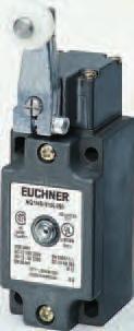
12 Limit switches according to EN 5 Limit switch type series NG.../NZ... Roller lever arm H(plastic roller) HS (steel roller) Cable entry M x.5 NG... NZ... Dimension drawing 5 + max. Switching elements ES 5 Snap-action contact element NC contact + NO contact ES 5 Snap-action contact element direct opening action contact + NO contact ES 58H Slow-action contact element direct opening action contact + NO contact ES 58H Slow-action contact element direct opening action contacts SK H Slow-action contact element direct opening action contacts + NO contact SK H Slow-action contact element direct opening action contacts + NO contact (for further details see page 9) Mx,5 LED function display red function display LED is available for the following voltage ranges: - V C/DC L V C ±5% L V C ±5% L djustment options Horizontal and vertical x 9 (see page 8). Switching direction Switches to the right, left and to both sides (see page 8). Switch travel diagrams Contacts Switching point open End position closed C Reset point C C ES5 ES5 ES58H If damaged or worn, safety switches should be replaced as a unit. Notes on installation for limit switches with safety switching elements To obtain the direct opening travel, the switching cam gap shown in the dimension 5 + must be complied with. ctuation elements such as cam approach guides must be firmly mounted in accordance EN 88, i.e. riveted, welded or otherwise secured against becoming loose. ES58H SKH SKH Subject to technical modifications; no responsibility is accepted for the accuracy of this information.
13 Limit switches according to EN 5 Technical data Parameters Value Unit Housing material nodized die-cast alloy Degree of protection according to IEC 59 IP 7 Installation position Optional Mechanical service life x switching cycles mbient temperature -5 to +8 C Weight pprox.. kg ctuator Roller lever arm Roller material Plastic (H) Steel (HS) pproach speed, max. ) m/min pproach speed, min.. m/min Repeat accuracy ±.5 Direct opening action contact according to IEC 97-5-, appendix K See symbol in switch travel diagram ctuating force, min. 5 N Switching elements ES 5 ES 58H ES 58H NC + NO NC + NO NC ES 5 SK H SK H NC + NO NC + NO NC + NO Switching principle Snap-action Slow-action contact element contact element with H-contact bridge Contact material Silver alloy, gold flashed Contact closing time < ms Contact bounce time < ms Rated impulse withstand voltage Uimp.5 kv Rated insulation voltage Ui 5 V Utilization category according to IEC C Ie Ue V - C5 Ie Ue V Ie Ue V DC Ie Ue V Ie Ue V Switching current min. at m Switching voltage V DC Conventional thermal current Ith Short-circuit protection according to IEC 9- (control circuit fuse) / gg Type of connection Screw terminal ) Conductor cross-section, max. x.5 ² ) The approach speed specified applies to an approach angle of. ) For wiring diagram see page 9. Ordering table Type Series Roller Switching Element Function Display None L L L NG...-M on request H NZ...-M Plastic roller NG...-M on request HS NZ...-M Steel roller Ordering example: Limit switch without safety function NG, cable entry, roller lever arm with steel roller HS, snap-action contact element 5, function display L - V, metric thread M x.5 M NGHS-5L-M Subject to technical modifications; no responsibility is accepted for the accuracy of this information.
14 Limit switches according to EN 5 Limit switch type series NG.../NZ... NZ... Roller lever arm H(plastic roller) HS (steel roller) Plug connectors SR and SR Dimension drawing 5 + max. Switching elements ES 5 Snap-action contact element NC contact + NO contact ES 5 Snap-action contact element direct opening action contact + NO contact ES 58H Slow-action contact element direct opening action contact + NO contact ES 58H Slow-action contact element direct opening action contacts SK H Slow-action contact element direct opening action contacts + NO contact SK H Slow-action contact element direct opening action contacts + NO contact (for further details see page 9) inserted inserted inserted LED function display red function display LED is available for the following voltage ranges: - V C/DC (as standard) L V C ±5% (on request) L V C ±5% (on request) L djustment options Horizontal and vertical x 9 (see page 8). SRWF SREF/SREF SRWF Switching direction Switches to the right, left and to both sides (see page 8). Switch travel diagrams Contacts Switching point open End position closed C Reset point C C ES5 ES5 ES58H If damaged or worn, safety switches should be replaced as a unit. Notes on installation for limit switches with safety switching elements To obtain the direct opening travel, the switching cam gap shown in the dimension 5 + must be complied with. ctuation elements such as cam approach guides must be firmly mounted in accordance EN 88, i.e. riveted, welded or otherwise secured against becoming loose. ES58H SKH SKH Subject to technical modifications; no responsibility is accepted for the accuracy of this information.
15 Limit switches according to EN 5 Technical data Parameters Value Unit Housing material nodized die-cast alloy Degree of protection according to IEC 59 IP 5 Installation position Optional Mechanical service life x switching cycles mbient temperature -5 to +8 C Weight pprox.. kg ctuator Roller lever arm Roller material Plastic (H) Steel (HS) pproach speed, max. ) m/min pproach speed, min.. m/min Repeat accuracy ±.5 Direct opening action contact according to IEC 97-5-, appendix K See symbol in switch travel diagram ctuating force, min. 5 N Switching elements ES 5 ES 58H ES 58H NC + NO NC + NO NC ES 5 SK H SK H NC + NO NC + NO NC + NO Switching principle Snap-action Slow-action contact element contact element with H-contact bridge Contact material Silver alloy, gold flashed Contact closing time < ms Contact bounce time < ms Rated impulse withstand voltage Uimp.5 kv Switching current min. at m Switching voltage V DC Conventional thermal current Ith Short-circuit protection according to IEC 9- (control circuit fuse) gg Type of connection Plug connector to DIN 5 ) Rated insulation voltage Ui with plug connector SR 5 V with plug connector SR 5 Rated impulse withstand voltage Uimp with plug connector SR.5 kv with plug connector SR.5 Utilization category according to IEC with plug connector SR C5 Ie Ue V Ie Ue V DC Ie Ue V Ie Ue V with plug connector SR C5 Ie Ue 5 V DC Ie Ue V ) The approach speed specified applies to an approach angle of. ) For wiring and derating diagram see page. Ordering table Type Series Roller Switching Element Plug Connector / Function Display SR SR SR without LED with L without LED NG H NZ... Plastic roller NG NZ... HS Steel roller Ordering example: Limit switch without safety function NG, plug connector, roller lever arm with steel roller HS, snap-action contact element 5, function display L - V NGHS-5L 89 9 Subject to technical modifications; no responsibility is accepted for the accuracy of this information. 5
16 Limit switches according to EN 5 Limit switch type series NG.../NZ... NZ... Roller lever arm H(plastic roller) HS(steel roller) M/SVM5 plug connector Dimension drawing 5 + Guide lug aligned max. 5 5 ø8 Switching elements ES 5 Snap-action contact element NC contact + NO contact ES 5 Snap-action contact element direct opening action contact + NO contact ES 58H Slow-action contact element direct opening action contact + NO contact ES 58H Slow-action contact element direct opening action contacts (for further details see page 9) 7 ±, + ±, 7, 5, 5, LED function display vailable on request djustment options Horizontal and vertical x 9 (see page 8). Switching direction Switches to the right, left and to both sides (see page 8).,5 ngled plug connector: Plug connector adjustable to a max. of 7 Default setting: cable exit to the right. Switch travel diagrams Contacts Switching point open End position closed C Reset point C C ES5 ES5 ES58H If damaged or worn, safety switches should be replaced as a unit. Notes on installation for limit switches with safety switching elements To obtain the direct opening travel, the switching cam gap shown in the dimension 5 + must be complied with. ctuation elements such as cam approach guides must be firmly mounted in accordance EN 88, i.e. riveted, welded or otherwise secured against becoming loose. ES58H Subject to technical modifications; no responsibility is accepted for the accuracy of this information.
17 Limit switches according to EN 5 Technical data Parameters Value Unit Housing material nodized die-cast alloy Degree of protection according to IEC 59 IP 7 Installation position Optional Mechanical service life x switching cycles mbient temperature -5 to +8 C Weight pprox.. kg ctuator Roller lever arm Roller material Plastic (H) Steel (HS) pproach speed, max. ) m/min pproach speed, min.. m/min Repeat accuracy ±.5 Direct opening action contact according to IEC 97-5-, appendix K See symbol in switch travel diagram ctuating force, min. 5 N Switching elements ES 5 ES 58H ES 58H NC + NO NC + NO NC ES 5 NC + NO Switching principle Snap-action Slow-action contact element contact element with H-contact bridge Contact material Silver alloy, gold flashed Contact closing time < ms Contact bounce time < ms Rated impulse withstand voltage Uimp. kv Rated insulation voltage Ui 5 V Utilization category according to IEC with SVM5 plug connector C5 Ie Ue V Ie Ue V DC Ie Ue V Ie Ue V Switching current min. at m Switching voltage V DC Conventional thermal current Ith Short-circuit protection according to IEC 9- (control circuit fuse) gg Type of connection M plug connector ) ) The approach speed specified applies to an approach angle of. ) For wiring diagram see page. Ordering table Type Series Roller Switching Element Plug Connector SVM5 NG H NZ... Plastic roller NG HS NZ... Steel roller Ordering example: Limit switch without safety function NG, plug connector, roller lever arm with steel roller HS, snap-action contact element 5, M plug with PE connection SVM5 NGHS-5SVM5 9 8 Subject to technical modifications; no responsibility is accepted for the accuracy of this information. 7
18 Limit switches according to EN 5 Limit switch type series NG.../NZ... djustable roller lever arm V (plastic) / P (plastic roller) VS (steel roller) / PS (steel roller) Cable entry M x.5 (plug connector on request) NZ... * * pproval applied Dimension drawing max. 7 ±, 7, 5, , ±, 59 Switching elements ES 5 Snap-action contact element NC contact + NO contact ES 5 Snap-action contact element direct opening action contact + NO contact ES 58H Slow-action contact element direct opening action contact + NO contact ES 58H Slow-action contact element direct opening action contacts SK H Slow-action contact element direct opening action contact + NO contact SK H Slow-action contact element direct opening action contact + NO contact (for further details see page 9) + NG... NZ... Mx,5 LED function display red function display LED is available for the following voltage ranges: - V C/DC (as standard) L V C ±5% (on request) L V C ±5% (on request) L djustment options Horizontal and vertical x 9 (see page 8). Switching direction Switches to the right, left and to both sides (see page 8). Switch travel diagrams Contacts Switching point open End position closed C Reset point If damaged or worn, safety switches should be replaced as a unit. C 5 +5 ES5 C 5 +5 ES ES58H Notes on installation for limit switches with safety switching elements To obtain the direct opening travel, the switching cam must actuate the lever arm to an angle of ctuation elements such as cam approach guides must be firmly mounted in accordance EN 88, i.e. riveted, welded or otherwise secured against becoming loose. ES58H SKH SKH 8 Subject to technical modifications; no responsibility is accepted for the accuracy of this information.
19 Limit switches according to EN 5 Technical data Parameters Value Unit Housing material nodized die-cast alloy Degree of protection according to IEC 59 IP 7 Installation position Optional Mechanical service life x switching cycles mbient temperature -5 to +8 C Weight pprox.. kg ctuator djustable Roller lever arm Roller material Plastic (V) Plastic (P) Steel (VS) Steel (PS) pproach speed, max. ) m/min pproach speed, min..5 m/min Direct opening action contact according to IEC 97-5-, appendix K See symbol in switch travel diagram ctuating force, min. 5 N Switching elements ES 5 ES 58H ES 58H NC + NO NC + NO NC ES 5 SK H SK H NC + NO NC + NO NC + NO Switching principle Snap-action Slow-action contact element contact bridge contact element with H-contact bridge Contact material Silver alloy, gold flashed Contact closing time < ms Contact bounce time < ms Rated impulse withstand voltage Uimp.5 kv Rated insulation voltage Ui 5 V Utilization category according to IEC C Ie Ue V - C5 Ie Ue V Ie Ue V DC Ie Ue V Ie Ue V Switching current min. at m Switching voltage V DC Conventional thermal current Ith Short-circuit protection according to IEC 9- (control circuit fuse) / gg Type of connection Screw terminal ) Conductor cross-section, max. x.5 ² ) The approach speed specified applies to an approach angle of. ) For wiring diagram see page 9. Ordering table Type Series Roller Switching Element Function Display None L NG...-M V Plastic roller VS Steel roller on request P Plastic roller NZ...-M PS Steel roller Ordering example: Limit switch with safety function NZ, cable entry, adjustable roller lever arm with plastic roller P, Snap-action contact element 5, metric thread M x.5 M NZP-5-M 88 Subject to technical modifications; no responsibility is accepted for the accuracy of this information. 9
20 Limit switches according to EN 5 Limit switch type series NG... Pivoted lever arm S (plastic rod) SM (aluminum rod) Cable entry M x.5 (plug connector on request) Dimension drawing ± 5 Switching elements ES 5 Snap-action contact element NC contact + NO contact (for further details see page 9) 7 75 LED function display red function display LED is available for the following voltage ranges: - V C/DC (as standard) L V C ±5% (on request) L V C ±5% (on request) L djustment options Horizontal and vertical x 9 (see page 8). Switching direction Switches to the right, left and to both sides (see page 8). 7, 7 ±, 5, ±, + 5, Mx,5 Switch travel diagrams Contacts Switching point open End position closed C Reset point C Subject to technical modifications; no responsibility is accepted for the accuracy of this information.
21 Limit switches according to EN 5 Technical data Parameters Value Unit Housing material nodized die-cast alloy Degree of protection according to IEC 59 IP 7 Installation position Optional Mechanical service life x switching cycles mbient temperature -5 to +8 C Weight pprox.. kg ctuator Pivoted lever arm Roller material Plastic (S) luminum (SM) pproach speed, max. m/min pproach speed, min..5 m/min Repeat accuracy ± ctuating force, min. 5 N Switching elements ES 5 NC + NO Switching principle Snap-action contact element Contact material Silver alloy, gold flashed Contact closing time < ms Contact bounce time < ms Rated impulse withstand voltage Uimp.5 kv Rated insulation voltage Ui 5 V Utilization category according to IEC C Ie Ue V C5 Ie Ue V DC Ie Ue V Switching current min. at m Switching voltage V DC Conventional thermal current Ith Short-circuit protection according to IEC 9- (control circuit fuse) / gg Type of connection Screw terminal ) Conductor cross-section, max. x.5 ² ) For wiring diagram see page 9. Ordering table Type Series Roller Switching Element Function Display None L NG...-M S plastic rod -5 SM luminum rod Ordering example: Limit switch without safety function NG, cable entry, pivoted arm lever with plastic rod S, snap-action contact element 5, function display L - V, metric thread M x.5 M NGS-5L-M Subject to technical modifications; no responsibility is accepted for the accuracy of this information.
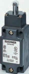
22 Limit switches according to EN 5 Limit switch type series NG.../NZ... Plunger actuator WO (Domed plunger) / KO (all plunger) DO (Chisel plunger) / RK (Roller plunger with small steel roller) Cable entry M x.5 NG... NZ... Dimension drawing + 97 max. 7 ±, 5, R 5, ±, + Direct opening + 7, Initial position 7 ± Mx,5 To obtain the direct opening travel, the switching cam gap shown in the dimension + must be complied with. ctuation elements such as cam approach guides must be firmly mounted in accordance EN 88, i.e. riveted, welded or otherwise secured against becoming loose. Switching elements ES 5 Snap-action contact element NC contact + NO contact ES 5 Snap-action contact element direct opening action contact + NO contact ES 58H Slow-action contact element direct opening action contact + NO contact ES 58H Slow-action contact element direct opening action contacts SK H Slow-action contact element direct opening action contacts + NO contact SK H Slow-action contact element direct opening action contacts + NO contact (for further details see page 9) LED function display red function display LED is available for the following voltage ranges: - V C/DC (as standard) L V C ±5% (on request) L V C ±5% (on request) L djustment options Horizontal x 9 (see page 8). Switch travel diagrams Contacts open closed ES5 ES5 ES58H ES58H SKH SKH WO Domed plunger Type (EN 5) DO Chisel plunger 5,5 ES5 ES5 ES58H ES58H SKH SKH KO all plunger RK Roller plunger small 5,5 Subject to technical modifications; no responsibility is accepted for the accuracy of this information.
23 Limit switches according to EN 5 Technical data Parameters Value Unit Housing material nodized die-cast alloy Degree of protection according to IEC 59 IP 7 Installation position Optional Mechanical service life x switching cycles mbient temperature -5 to +8 C Weight pprox.. kg ctuator Domed plunger Chisel plunger all plunger Roller plunger (WO) (DO) (KO) Small (RK) pproach speed, max. ) 5 m/min pproach speed, min.. m/min Repeat accuracy ) ±.. Direct opening action contact according to IEC 97-5-, appendix K See symbol in switch travel diagram ctuating force, min. 5 N Switching elements ES 5 ES 58H ES 58H NC + NO NC + NO NC ES 5 SK H SK H NC + NO NC + NO NC + NO Switching principle Snap-action Slow-action contact element contact element with H-contact bridge Contact material Silver alloy, gold flashed Contact closing time < ms Contact bounce time < ms Rated impulse withstand voltage Uimp.5 kv Rated insulation voltage Ui 5 V Utilization category according to IEC C Ie Ue V - C5 Ie Ue V Ie Ue V DC Ie Ue V Ie Ue V Switching current min. at m Switching voltage V DC Conventional thermal current Ith Short-circuit protection according to IEC 9- (control circuit fuse) / gg Type of connection Screw terminal ) Conductor cross-section, max. x.5 ² ) The approach speed specified applies in conjunction with EUCHNER control cams is in accordance with DIN 99. ) For wiring diagram see page 9. ) The reproducible repeat accuracy refers to the plunger s axial travel, after a run-in of approx. switching cycles Ordering table Type Series Roller Switching Element Function Display None L NG...-M on request NZ...-M WO Domed plunger NG...-M NZ...-M DO Chisel plunger on request NG...-M NZ...-M RK Roller plunger small on request NG...-M KO all plunger on request Ordering example: Limit switch without safety function NZ, cable entry, domed plunger WO, snap-action contact element 5, function display L - V, metric thread M x.5 M NZWO-5L-M Subject to technical modifications; no responsibility is accepted for the accuracy of this information.
24 Limit switches according to EN 5 Limit switch type series NG.../NZ... NZ... Plunger actuator WO(Domed plunger) / KO (all plunger) DO (Chisel plunger) / RK (Roller plunger with small steel roller) Plug connectors SR and SR Dimension drawing max. ±, 8x + 5, ±, Direct opening 5 + inserted 5, 7, Initial position 7 ± 75 inserted Mx, , inserted Switching elements ES 5 Snap-action contact element NC contact + NO contact ES 5 Snap-action contact element direct opening action contact + NO contact ES 58H Slow-action contact element direct opening action contact + NO contact ES 58H Slow-action contact element direct opening action contacts SK H Slow-action contact element direct opening action contacts + NO contact SK H Slow-action contact element direct opening action contacts + NO contact (for further details see page 9) LED function display red function display LED is available for the following voltage ranges: - V C/DC (as standard) L V C ±5% (on request) L V C ±5% (on request) L 55,5 SRWF 8 SREF/SREF SRWF djustment options Horizontal x 9 (see page 8). Switch travel diagrams To obtain the direct opening travel the switching cam gap shown in the dimension + must be complied with. ctuation elements such as cam approach guides must be firmly mounted in accordance EN 88, i.e. riveted, welded or otherwise secured against becoming loose. Contacts open closed ES5 ES5 ES58H ES58H SKH SKH ,5 5 WO Domed plunger Type (EN 5) DO Chisel plunger ES5 ES5 ES58H ES58H SKH SKH ,5 5 KO all plunger RK Roller plunger small Subject to technical modifications; no responsibility is accepted for the accuracy of this information.
25 Limit switches according to EN 5 Technical data Parameters Value Unit Housing material nodized die-cast alloy Degree of protection according to IEC 59 IP 5 Installation position Optional Mechanical service life x switching cycles mbient temperature -5 to +8 C Weight pprox.. kg ctuator Domed plunger Chisel plunger all plunger Roller plunger (WO) (DO) (KO) Small (RK) pproach speed, max. ) 5 m/min pproach speed, min.. m/min Repeat accuracy ) ±.. Direct opening action contact according to IEC 97-5-, appendix K See symbol in switch travel diagram ctuating force, min. 5 N Switching elements ES 5 ES 58H ES 58H NC + NO NC + NO NC ES 5 SK H SK H NC + NO NC + NO NC + NO Switching principle Snap-action Slow-action contact element contact element with H-contact bridge Contact material Silver alloy, gold flashed Contact closing time < ms Contact bounce time < ms Rated impulse withstand voltage Uimp.5 kv Switching current min. at m Switching voltage V DC Conventional thermal current Ith Short-circuit protection according to IEC 9- (control circuit fuse) gg Type of connection Plug connector to DIN 5 ) Rated insulation voltage Ui with plug connector SR 5 with plug connector SR 5 V Rated impulse withstand voltage Uimp with plug connector SR.5 kv with plug connector SR.5 Utilization category according to IEC with plug connector SR C5 Ie Ue V Ie Ue V DC Ie Ue V Ie Ue V with plug connector SR C5 Ie Ue 5 V DC Ie Ue V ) The approach speed specified applies in conjunction with EUCHNER control cams is in accordance with DIN 99. ) For wiring and derating diagram see page. ) The reproducible repeat accuracy refers to the plunger s axial travel, after a run-in of approx. switching cycles Ordering table Type Series Roller Switching Element Function Display None L NG on request NZ... WO Domed plunger NG DO NZ... Chisel plunger on request NG on request NZ... RK Roller plunger small on request NG... KO all plunger -5 9 on request Subject to technical modifications; no responsibility is accepted for the accuracy of this information. 5
26 Limit switches according to EN 5 Limit switch type series NG.../NZ... NZ... Plunger actuator WO(Domed plunger) / KO (all plunger) DO (Chisel plunger) / RK (Roller plunger with small steel roller) M/SVM5 plug connector Dimension drawing Guide lug aligned max. 5 8x Direct opening Initial position Switching elements ES 5 Snap-action contact element NC contact + NO contact ES 5 Snap-action contact element direct opening action contact + NO contact ES 58H Slow-action contact element direct opening action contact + NO contact ES 58H Slow-action contact element direct opening action contacts (for further details see page 9) ± LED function display red function display LED is available for the following voltage ranges: - V C/DC (as standard) L V C ±5% (on request) L V C ±5% (on request) L 7 ±, ±, 5, 5, Mx,5 djustment options Horizontal x 9 (see page 8).,5 7, ngled plug connector: Plug connector adjustable to a max. of 7 Default setting: cable exit to the right. To obtain the direct opening travel the switching cam gap shown in the dimension + must be complied with. ctuation elements such as cam approach guides must be firmly mounted in accordance EN 88, i.e. riveted, welded or otherwise secured against becoming loose. Switch travel diagrams ES5 ES5 ES58H ES58H Contacts open closed WO Domed plunger Type (EN 5) DO Chisel plunger ES5 ES5 ES58H ES58H KO all plunger RK Roller plunger small 5 Subject to technical modifications; no responsibility is accepted for the accuracy of this information.
27 Limit switches according to EN 5 Technical data Parameters Value Unit Housing material nodized die-cast alloy Degree of protection according to IEC 59 IP 7 Installation position Optional Mechanical service life x switching cycles mbient temperature -5 to +8 C Weight pprox.. kg ctuator Domed plunger Chisel plunger all plunger Roller plunger (WO) (DO) (KO) Small (RK) pproach speed, max. ) 5 m/min pproach speed, min.. m/min Repeat accuracy ) ±.. Direct opening action contact according to IEC 97-5-, appendix K See symbol in switch travel diagram ctuating force, min. 5 N Switching elements ES 5 ES 58H ES 58H NC + NO NC + NO NC ES 5 NC + NO Switching principle Snap-action Slow-action contact element contact element with H-contact bridge Contact material Silver alloy, gold flashed Contact closing time < ms Contact bounce time < ms Rated impulse withstand voltage Uimp. kv Rated insulation voltage Ui 5 V Utilization category according to IEC with SVM5 plug connector C5 Ie Ue V Ie Ue V DC Ie Ue V Ie Ue V Switching current min. at m Switching voltage V DC Conventional thermal current Ith Short-circuit protection according to IEC 9- (control circuit fuse) gg Type of connection M plug connector ) ) The approach speed specified applies in conjunction with EUCHNER control cams is in accordance with DIN 99. ) For wiring diagram see page. ) The reproducible repeat accuracy refers to the plunger s axial travel, after a run-in of approx. switching cycles Ordering table Type Series Roller Switching Element Plug Connector SVM5 NG WO NZ... Domed plunger NG DO NZ... Chisel plunger NG RK NZ... Roller plunger small NG... KO all plunger Ordering example: Limit switch without safety function NG, plug connector, small roller plunger with steel roller RK, snap-action contact element 5, M plug with PE connection SVM5 NGRK-5SVM5 89 Subject to technical modifications; no responsibility is accepted for the accuracy of this information. 7
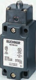
28 Limit switches according to EN 5 Limit switch type series NG.../NZ... Plunger actuator RG (Roller plunger - plastic roller) RS (Roller plunger - steel roller) RL (Extended roller plunger) Cable entry M x.5 NG... NZ... Dimension drawing + max. Direct opening Initial position Switching elements ES 5 Snap-action contact element NC contact + NO contact ES 5 Snap-action contact element direct opening action contact + NO contact ES 58H Slow-action contact element direct opening action contact + NO contact ES 58H Slow-action contact element direct opening action contacts SK H Slow-action contact element direct opening action contacts + NO contact SK H Slow-action contact element direct opening action contacts + NO contact (for further details see page 9) LED function display red function display LED is available for the following voltage ranges: - V C/DC (as standard) L V C ±5% (on request) L V C ±5% (on request) L Mx,5 djustment options Horizontal x 9 (see page 8). If damaged or worn, safety switches should be replaced as a unit. Switch travel diagrams Notes on installation for limit switches with safety switching elements To obtain the direct opening travel, the switching cam gap shown in the dimension + must be complied with. ctuation elements such as cam approach guides must be firmly mounted in accordance EN 88, i.e. riveted, welded or otherwise secured against becoming loose. Contacts open closed ES5 ES5 ES58H ES58H SKH SKH ,5 RG Plastic roller RS Steel roller RL Roller plunger plunger 8 Subject to technical modifications; no responsibility is accepted for the accuracy of this information.
29 Limit switches according to EN 5 Technical data Parameters Value Unit Housing material nodized die-cast alloy Degree of protection according to IEC 59 IP 7 Installation position Optional Mechanical service life x switching cycles mbient temperature -5 to +8 C Weight pprox.. kg ctuator Roller plunger Roller plunger Roller plunger Plastic roller (RG) Steel (RS) Extended (RL) pproach speed, max. ) m/min pproach speed, min.. m/min Repeat accuracy ) ±. Direct opening action contact according to IEC 97-5-, appendix K See symbol in switch travel diagram ctuating force, min. 5 N Switching elements ES 5 ES 58H ES 58H NC + NO NC + NO NC ES 5 SK H SK H NC + NO NC + NO NC + NO Switching principle Snap-action Slow-action contact element contact element with H-contact bridge Contact material Silver alloy, gold flashed Contact closing time < ms Contact bounce time < ms Rated impulse withstand voltage Uimp.5 kv Rated insulation voltage Ui 5 V Utilization category according to IEC C Ie Ue V - C5 Ie Ue V Ie Ue V DC Ie Ue V Ie Ue V Switching current min. at m Switching voltage V DC Conventional thermal current Ith Short-circuit protection according to IEC 9- (control circuit fuse) / gg Type of connection Screw terminal ) Conductor cross-section, max. x.5 ² ) The approach speed specified applies in conjunction with EUCHNER control cams is in accordance with DIN 99. ) For wiring diagram see page 9. ) The reproducible repeat accuracy refers to the plunger s axial travel, after a run-in of approx. switching cycles Ordering table Type Series Roller Switching Element Function Display None L NG...-M NZ...-M RG Roller plunger Plastic roller NG...-M NZ...-M RS Roller plunger Steel roller NG...-M NZ...-M RL Extended roller plunger Ordering example: Limit switch with safety function NZ, cable entry, Roller plunger with plastic roller RG, snap-action contact element 5, function display L - V, metric thread M x.5 M NZRG-5L-M 89 5 Subject to technical modifications; no responsibility is accepted for the accuracy of this information. 9
30 Limit switches according to EN 5 Limit switch type series NG.../NZ... NZ... Plunger actuator RG (Roller plunger - plastic roller) RS (Roller plunger - steel roller) RL (Extended roller plunger) Plug connectors SR and SR Dimension drawing ±, max. R Direct opening Initial position + 5 ± + 5, 5, ±, 7, ø Switching elements ES 5 Snap-action contact element NC contact + NO contact ES 5 Snap-action contact element direct opening action contact + NO contact ES 58H Slow-action contact element direct opening action contact + NO contact ES 58H Slow-action contact element direct opening action contacts SK H Slow-action contact element direct opening action contacts + NO contact SK H Slow-action contact element direct opening action contacts + NO contact (for further details see page 9) LED function display red function display LED is available for the following voltage ranges: - V C/DC (as standard) L V C ±5% (on request) L V C ±5% (on request) L 5, djustment options Horizontal x 9 (see page 8). 55,5 8 If damaged or worn, safety switches should be replaced as a unit. SRWF Switch travel diagrams SREF/SREF SRWF Notes on installation for limit switches with safety switching elements To obtain the direct opening travel, the switching cam gap shown in the dimension + must be complied with. ctuation elements such as cam approach guides must be firmly mounted in accordance EN 88, i.e. riveted, welded or otherwise secured against becoming loose. Contacts open closed ES5 ES5 ES58H ES58H SKH SKH ,5 RG Plastic roller RS Steel roller RL Roller plunger plunger Subject to technical modifications; no responsibility is accepted for the accuracy of this information.
31 Limit switches according to EN 5 Technical data Parameters Value Unit Housing material nodized die-cast alloy Degree of protection according to IEC 59 IP 5 Installation position Optional Mechanical service life x switching cycles mbient temperature -5 to +8 C Weight pprox.. kg ctuator Roller plunger Roller plunger Roller plunger Plastic roller (RG) Steel (RS) Extended (RL) pproach speed, max. ) m/min pproach speed, min.. m/min Repeat accuracy ) ±. Direct opening action contact according to IEC 97-5-, appendix K See symbol in switch travel diagram ctuating force, min. 5 N Switching elements ES 5 ES 58H ES 58H NC + NO NC + NO NC ES 5 SK H SK H NC + NO NC + NO NC + NO Switching principle Snap-action Slow-action contact element contact element with H-contact bridge Contact material Silver alloy, gold flashed Contact closing time < ms Contact bounce time < ms Rated impulse withstand voltage Uimp.5.5 kv Switching current min. at m Switching voltage V DC Conventional thermal current Ith Short-circuit protection according to IEC 9- (control circuit fuse) gg Type of connection Plug connector to DIN 5 ) Rated insulation voltage Ui with plug connector SR 5 with plug connector SR 5 V Rated impulse withstand voltage Uimp with plug connector SR.5 kv with plug connector SR.5 Utilization category according to IEC with plug connector SR C5 Ie Ue V Ie Ue V DC Ie Ue V Ie Ue V with plug connector SR C5 Ie Ue 5 V Ie Ue 5 V DC Ie Ue V Ie Ue V ) The approach speed specified applies in conjunction with EUCHNER control cams is in accordance with DIN 99. ) For wiring and derating diagram see page. ) The reproducible repeat accuracy refers to the plunger s axial travel, after a run-in of approx. switching cycles Ordering table Type Series Roller Switching Element Function Display None L NG NZ... RG Roller plunger Plastic roller NG on request NZ... RS Roller plunger Steel roller NG NZ... RL Extended roller plunger Subject to technical modifications; no responsibility is accepted for the accuracy of this information.
Limit Switches according to EN 50041
 Limit Switches according to EN 5 More than safety. utomation More than safety. Emil Euchner, the company s founder and inventor of the multiple limit switch, circa 98. round the world the Swabian specialists
Position Switches according to EN 50041
 Position Switches according to EN 5 More than safety. utomation More than safety. Emil Euchner, the company s founder and inventor of the multiple limit switch, circa 98. round the world the Swabian specialists
PRECISION SWITCHES CONTENTS
 PRECISION SWITCHES CONTENTS Limit Switches to EN50041 LIMIT SWITCHES The TEKNIC Limit Switch Precision, Reliability and Versatility. The TEKNIC Limit switch is a versatile unit, according to the EUROPEAN
Safety Switches NP GP TP. More than safety.
 Safety Switches NP GP TP More than safety. Safety More than safety. Emil Euchner, the company s founder and inventor of the multiple limit switch, circa 1928. Around the world the Swabian specialists in
LK Position Switches TECHNICAL DATASHEET.
 LK Position Switches Technopolymer housing, one conduit entry Protection degree IP6 according to EN 60529 contact blocks available 46 actuators available Versions with stainless steel external parts Versions
Double insulated, types XCK-P and XCK-T. With head for linear movement (plunger) operators
 operators") Double insulated, types XCK-P and XCK-T Presentation XCK-P with 1 cable entry, conforming to CENELEC EN 57 With head for linear movement (plunger) operators Page 18 With head for rotary movement (lever)
Double insulated, types XCK-P and XCK-T Presentation XCK-P with 1 cable entry, conforming to CENELEC EN 57 With head for linear movement (plunger) operators Page 18 With head for rotary movement (lever)
Datasheet - MV8H Y
 18.03.2014-17:45:05h Datasheet - MV8H 330-11Y Position switch / light Position switch / M 330 / M 330 Roller lever 8H Preferred typ Metal enclosure Long life 40 mm x 76 mm x 40 mm ( basic component) Suitable
Compact plastic limit switches with positive opening mechanism
 Compact limit switches with positive opening mechanism LJK-N Series Positive opening mechanism Positive opening mechanism meets standards worldwide. A wide variety of actuators is available. The LJK-N
FL series position switches
 FL series position switches Selection diagram 0 08 0 9 0 0 0 Ball Ø. External rubber Ball Ø 8 mm, mm, stainless Glass fibre rod gasket stainless steel steel Adjustable lever Adjustable safety lever Bistable
Limit Switch - Safety Type with pull button reset Plastic Body IP65 and Metal Body IP66
 Limit Switch - Safety Type with pull button reset Plastic Body IP65 and Metal Body IP66 Double Insulation (for thermoplastic type) High mechanical resistant Degree of protection IP65 (thermoplastic) IP66
Compact plastic limit switches with positive opening mechanism
 Compact limit switches with positive opening mechanism LJK-NSeries Positive opening mechanism Positive opening mechanism meets standards worldwide. A wide variety of actuators is available. The LJK-N conforms
Safety rope switches with reset for emergency stop
 Safety rope switches with reset for emergency stop Selection diagram 8 8 83 ACTUATORS ACTUATORS CONTACT BLOCKS 18 9 21 1NO+ FP FD FL FC 22 33 34 LED signalling light CONDUIT ENTRIES For other available
Position switches FR series
 Position switches FR series Selection diagram 01 A1 08 14 01-7 0 A 05 A5 external rubber gasket external rubber gasket for electrical panels external rubber gasket external rubber gasket 0 1 5 34 50 33
SERIES Z/T236. Safety-Rated, Positive-Break Miniature DIN Limit Switches. Features & Benefits. Description. Typical Applications ORDERING GUIDE
 SERIES Z/T23 Safety-Rated, Positive-Break Miniature DIN Limit Switches Features & Benefits Positive-Break NC contacts won t stick or weld shut. Watertight design meets IP washdown requirements. Rugged,
Limit Switch - Prewired Type Metal Body
 Limit Switch - Prewired Type Metal Body Sealed with epoxy resin al the base of the box Degree of protection IP67 Thermoplastic material or diecast zinc alloy body Positive Opening Operation Minimum Actuation
Safety Switches with Separate Actuator, Plastic Housing
 Safety Switces wit Separate Actuator, Plastic Housing Selection table for safety switces Mounting AS Mounting to DIN EN 5007 AB Mounting wit 0 mm spacing M SM Tread M0 x.5 for cable gland M -pin ; 6 pin
S840, S845, S846 Series Single-break changeover, NC or NO contacts, positive opening operation and wiping action Catalogue D40.en
 Snap-action switches S80, S85, S86 Series Single-break changeover, NC or NO contacts, positive opening operation and wiping action Catalogue D0.en Snap-action switches, S80, S85, S86 Series Single-break
Limit switches. 7 Page 71. Presentation. OsiSense XC Basic Compact design, plastic, with reset knob, types XCNR and XCNTR. b XCNR.
 Presentation Compact design, plastic, with reset knob, types XCNR and XCNTR b XCNR with cable entry v With head for linear movement (plunger) Page v With head for rotary movement (lever) Page b XCNTR with
l Snap-Action Switches
 Connect - Contact - Control 2 Brochure l Snap-Action Switches Snap-action switches I Page 2 Page 3 I Snap-action switches Double Safety A sky diver's life depends on his equipment. In case of emergency
Position switches FD series
 Position switches FD series Selection diagram 01 08 11 18 19 02 04 05 Ø 8 mm Ø, mm external rubber stainless steel stainless steel fibber glass rod gasket sphere sphere 51 52 5 56 41 42 adjustable lever
Control Equipment. ATHEX bvba Tel: +32 (0) Fax: +32 (0) Alpenroosbaan 2, 2900 Schoten, België
 Fax: +32 (0) Alpenroosbaan 2, 2900 Schoten, België") Control Equipment 01616E00 Position switches are used to monitor the position of moving parts of machines and plant. Can be used in safety circuits, as the device satisfies EN 60 947-5-1/DIN VDE 0660 part
Control Equipment 01616E00 Position switches are used to monitor the position of moving parts of machines and plant. Can be used in safety circuits, as the device satisfies EN 60 947-5-1/DIN VDE 0660 part
Limit Switches - Safety Type Plastic Body IP65 and Metal Body IP66
 Limit Switches - Safety Type Plastic Body IP65 and Metal Body IP66 Product Description They are developed in order to be used for following operations: For monitoring and protection of industrial machines,
F E - Electromagnetic Safety Switch With Separated Actuator. 1 Code Construction. Casing: P: Plastic casing
 Electromagnetic Safety Switch With Separated 1 Code Construction F E - Casing: P: Plastic casing Cable inlet: 5: 3 x (M20x1) Type of FEP: E: Electrical block ( b with excited ) M: Mechanical block ( b
Switches with manual reset
 Switches with manual reset Selection diagram 01-W 02-W 05-W 0-W -W -H0W 16-W 16-H0W Ø mm roller Ø mm roller Ø mm roller Ø mm roller 0-W 1-W 51-W 52-W 5-W 55-W -W adjustable lever safety adjustable lever
Safety rope switch with reset for emergency stop
 Safety rope switch with reset for emergency stop Selection diagram 8 8 83 ACTUATORS ACTUATORS CONTACT BLOCKS 18 9 21 1NO+,, FP FD FL FC 22 33 34,, CONDUIT ENTRIES Threaded conduit entries (standard) With
XCKJ390559H29EX limit switch XCKJ - round rod Ø 6 mm - 2NC + NO - ATEX/IECEx
 Characteristics limit switch XCKJ - round rod Ø 6 mm - 2NC + NO - ATEX/IECEx Main Range of product OsiSense ATEX D Series name Standard format Product or component type Limit switch Device short name XCKJ
Limit Switches - Limit Type Plastic Body IP65
 Limit Switches - Limit Type Plastic Body IP65 Double Insulation Degree of protection IP65 Reinforced UL-V thermoplastic fiber-glass body Positive Opening Operation Minimum Actuation Force/Torque Minimum
SWITCHGEAR. 4G cam switches
 SWITCHGEAR 178 4G cam switches ENERGY SAFELY SWITCHED 179 SWITCHGEAR 180 GENERAL INFORMATION 4G-series cam switches are low voltage switches, designed according to the latest knowledge about switchgear
Sealed limit switches. If your application depends on it SERIE MP700
 Microswitches and sealed position switches If your application depends on it SERIE MP700 Plastic or metal case IP67 protection 30 mm or 35 mm case width Wide temperature range Sealed limit switches Serie
FOOT SWITCHES
 - 83 - FOOT SWITCHES PS... / PD... Foot Switches Double insulation - Plastic Casing IP65 Description Applications Foot switch operated machines such as: shearing machines, spinning machines, spinning lathers,
Position switches FR series
 Position switches FR series Selection diagram 0 A 08 0-0 A A 0 A external rubber gasket external rubber gasket for electrical panels external rubber gasket external rubber gasket external rubber gasket
LR-LX-LK-LW Safety Switches with separate actuator
 LR-LX-LK-LW Safety Switches with separate actuator Technopolymer housing, from one to three conduit entries Protection degree IP67 15 contact blocks available 8 stainless steel actuators available Versions
Series S847 Changeover switches featuring wiping, galvanically isolated, double-break contacts and positive opening operation Catalogue D47.
 Snap-action switches Changeover switches featuring wiping, galvanically isolated, double-break contacts and positive opening operation Catalogue D47.en Snap-action switches, S847 Series Dual changeover
PRODUCT SPECIFICATION. Foot Switches. Series.
 PRODUCT SPECIFICATION Foot 46 Series www.wernerelektrik.com Foot Switch Structures...1 Technical Data...2 Model Number Structure - Foot...3 Dimensions...4 Precautions... Foot WERNERS are Rigorous and tough.
Limit switches 3. Page 92. Page 92
 Presentation, general characteristics b XCKS with cable entry v With head for linear movement (plunger) Page v With head for rotary movement (lever) Page Environment characteristics Conformity to standards
Safety Switches with Separate Actuator, Metal Housing
 Safety Switces wit Separate Actuator, Metal Housing Selection table for safety switces STA wit guard locking and guard lock monitoring Version standard TW One actuating ead made of metal TWIN, 2 actuating
Safety switches with separate actuator
 Safety switches with separate actuator Selection diagram VF KEYD VF KEYD1 VF KEYD VF KEYD VF KEYD5 ACTUATORS VF KEYD6 VF KEYD7 VF KEYD8 VF KEYD10 VF KEYD11 FR FX FK FW 5 6 7 11 1 14 NC NC slow action slow
Microswitches MK series
 Microswitches MK series Microswitches of MK series have been developed in order to add new features to traditional and tested microswitches of Pizzato Elettrica. These products have been designed with
AF40... AF96 3-pole contactors Technical data
 Main pole - Utilization characteristics according to IEC Standards IEC 60947- / 60947-4- and EN 60947- / 60947-4- Rated operational voltage Ue max. 690 V Rated frequency (without derating) 50 / 60 Hz Conventional
Limit Switches - Limit Type (PS31L) Plastic Body IP65
 Plastic Body IP65") Limit Switches - Limit Type (PSL) Plastic Body IP65 Double Insulation Degree of protection IP65 Reinforced UL-V thermoplastic fiber-glass body Positive Opening Operation Minimum Actuation Force/Torque
Limit Switches - Limit Type (PSL) Plastic Body IP65 Double Insulation Degree of protection IP65 Reinforced UL-V thermoplastic fiber-glass body Positive Opening Operation Minimum Actuation Force/Torque
LS Series Limit Switches. Short Form Catalogue AC1300 ABB
 Short Form Catalogue LS Series Limit Switches AC ABB LS Series Limit Switches Foot Switches Contents Panorama... 2 Limit Switches - Plastic Casing and Metal Casing... 12 Safety Limit Switches - Plastic
Miniature microswitches - Positive break
 1 Miniature microswitches - Positive break 81607 Coil spring snap-action mechanism with wiping contacts Positive opening action according to IEC 6097-5-1 Annex K atings from 10 ma Vc to 6 A 250 Va Very
Rotary limit switches FCR FGR series
 Rotary limit switches FCR FGR series Rotary control switches with 00mm rods from up to positions. Control switches with rotary gear from up to 00 rpm with or micro switches. 0 Rotary limit switches FCR
Safety switches with solenoid and separate actuator
 4 Safety switches with and separate Selection diagram VF KEYF20 VF KEYF21 VF KEYF22 VF KEYF28 CTUTORS HED TYPE ND WORKING PRINCIPE D locked with de-energized E locked with energized SIGNING ED B Z two
Single foot switches - PX and PA series
 Single foot switches - PX and PA series Description The PX and PA foot switches are traditional products of Pizzato Elettrica that have recorded a continuous growth and success in the market. Modified
Limit switches. 6 Thermoplastic roller lever 1 direction of actuation SEN TRONIC AG. Presentation
 Presentation Variable composition Spring-rod lever with thermoplastic end () Spring-rod lever, metal () Variable length thermoplastic roller lever () Round rod lever, thermoplastic, Ø mm L = mm () ZCK
K50H004UP cam changeover switch - 4-pole A - screw mounting
 Characteristics cam changeover switch - 4-pole - 60-50 A - screw mounting Main Range of product Product or component type Component name [Ith] conventional free air thermal current Mounting location Fixing
Limit Switches - Limit Type (PS21L) Metal Body IP66
 Metal Body IP66") Limit Switches - Limit Type (PS21L) Metal Body IP66 High mechanical resistance Degree of protection IP66 Zinc alloy (Zamack) or aluminium body Positive Opening Operation Minimum Actuation Force/Torque
Limit Switches - Limit Type (PS21L) Metal Body IP66 High mechanical resistance Degree of protection IP66 Zinc alloy (Zamack) or aluminium body Positive Opening Operation Minimum Actuation Force/Torque
Limit Switches - Limit Type Plastic Body IP65
 Limit Switches - Limit Type Plastic Body IP65 Double Insulation Degree of protection IP65 Reinforced UL-V thermoplastic fiber-glass body Positive Opening Operation Minimum Actuation Force/Torque Minimum
Metal limit switches are made of zinc alloy and have a degree of protection of IP67 and NEMA Type 4, 4X.
 Limit switches pre-wired 3mm & 35mm Metal & plastic casings Limit switches Description Plastic are made of reinforced UL-VO thermoplastic fiberglass, offering double insulation and protection
Recommended use With its standard enclosure, the ENM2 limit switch can be used universally in all industrial and safety applications.
 Metal-Enclosed Limit Switches ENM2 Recommended use With its standard enclosure, the ENM2 limit switch can be used universally in all industrial and safety applications. Product advantages Standard switch
K30H001YP cam star-delta switch - 3-pole A - screw mounting
 Characteristics cam star-delta switch - 3-pole - 60-32 A - screw mounting Main Range of product Product or component type Component name [Ith] conventional free air thermal current Mounting location Fixing
For full product information, visit Use the SpeedSpec Code or scan the QR Code for quick access to the specific web page.
 Safety Interlock Switches D4JL D4JL For full product information, visit www.sti.com. Use the SpeedSpec Code or scan the QR Code for quick access to the specific web page. uard Lock Safety-Door Switch Holding
Position Switches Series 8074/2
 www.stahl.de > Ex e metal enclosure > Operating temperature range -40 C... +70 C > Dimensions and characteristic values according to EN 50041 > Degree of protection IP66 > Extensive assortment of actuators,
Floor and fine adjustment switches
 Floor and fine adjustment switches 6 Introduction 6-2 AS 1 6-3 ASH 2 6-4 AFH 2 6-5 Reference table technical data 6-6 Universal switches 6-7 Floor and fine adjustment switches / Introduction ➀ ➁ ➂ Floor
Limit switches. Metal. Limit Switches Metal casing, 30mm, 40mm & 60mm
 Limit Switches casing, 3mm, 4mm & 6mm Description are made of aluminum alloy and have a degree of protection of IP 66 and UL type 4X. The casings come in 3 dimensions: LS3M, 3mm width. LS4M, 4mm width.
Position switches FC series
 A Position switches FC series Selection diagram 0 08 8 9 0 0 0 Ø 8 mm Ø, mm external rubber stainless steel stainless steel fiber glass rod gasket sphere sphere 6 adjustable lever safety adjustable lever
Safety rope switch without reset for simple stop
 afety rope switch without reset for simple stop election diagram FP 4-M2 FD 4-M2 FL 4-M2 FR 4-M2 FM 4-M2 FX 4-M2 FZ 4-M2 ACTUATOR 9 ACTUATOR 9 0 CONTACT BLOCK 1 9 21 1NO+ FP FD FL FC 33 34 CONDUIT ENTRIE
Safety switches with solenoid and separate actuator
 4 Safety switches with solenoid and separate Selection diagram VF KEYF20 VF KEYF VF KEYF22 VF KEYF28 CTUTORS D1D locked with De-energized solenoid WORKING PRINCIPLE D1E locked with Energized solenoid D5D
Ordering details. Approval. Classification. Global Properties :18:33h. Solenoid interlock / AZM 161
 10.06.2016 10:18:33h Datasheet AZM 161SK 12/12RKED/TU 110/230 Solenoid interlock / AZM 161 Thermoplastic enclosure Double insulated Interlock with protection against incorrect locking. 130 mm x 90 mm x
LJASeries. Limit Switches with Positive Opening Mechanism
 Limit Switches with Positive Opening Mechanism LJASeries Snap action limit switches with positive opening mechanism enables general industrial machines to comply with EC directives and to acquire CE marking.
Limit Switches with Positive Opening Mechanism
 Limit Switches with Positive Opening Mechanism LJA Series Positive opening mechanism Snap action limit switches with positive opening mechanism enables general industrial machines to comply with EC directives
SFS-UFS Single Foot Switches
 SFS-UFS Single Foot Switches Technopolymer housing, shock proof Protection degree IP53 or IP65 13 contact blocks available Various auxiliary devices available UFS Series SFS Series Options & Ordering Codes
XCKP2145P16 limit switch XCKP - th.plastic roller lever var.length - 1NC+1NO - snap - M16
 Characteristics limit switch XCKP - th.plastic roller lever var.length - 1NC+1NO - snap - M16 Product availability : Non-Stock - Not normally stocked in distribution facility Price* : 47.90 USD Main Range
AZM 161SK 12/12RKED/TU 024
 10.06.2016 10:17:13h Datasheet AZM 161SK 12/12RKED/TU 024 Solenoid interlock / AZM 161 Thermoplastic enclosure Double insulated Interlock with protection against incorrect locking. 130 mm x 90 mm x 30
Limit Switches - Limit Type (PS42L) Plastic Body IP65
 Plastic Body IP65") Limit Switches - Limit Type (PS42L) Plastic Body IP65 Double Insulation Degree of protection IP65 Reinforced UL-V thermoplastic fiber-glass body Positive Opening Operation Minimum Actuation Force/Torque
Limit Switches - Limit Type (PS42L) Plastic Body IP65 Double Insulation Degree of protection IP65 Reinforced UL-V thermoplastic fiber-glass body Positive Opening Operation Minimum Actuation Force/Torque
Applications Mill Mill Mill Mill. 9007T Convertible sequence. L100 Fixed sequence. Extra heavy duty contact ratings. Extra heavy duty contact ratings
 Selection Guide Severe Duty Mill and Foundry Switches pplications Mill Mill Mill Mill Design 9007T Convertible sequence L0 Fixed sequence L14 Single Cable Pulls Fixed sequence L525 elt Conveyor Fixed sequence
Safety switches with separate actuator
 Safety switches with separate actuator Selection diagram VF KEYD VF KEYD1 VF KEYD VF KEYD VF KEYD5 VF KEYD6 VF KEYD7 VF KEYD8 VF KEYD10 VF KEYD11 ACTUATORS CONTACT BLOCKS FR FX FK FW 5 6 7 11 1 14 NC NC
CTX 3 Control relays Cat. N (s) : /06/09..14/16/19..24/26/29
 : /06/09..14/16/19..24/26/29") 87045 LIMOGES Cedex Telephone: +33 5 55 06 87 87 FAX: +33 5 55 06 88 88 CTX 3 Control relays Cat. N (s) : 4 168 00..04/06/09..14/16/19..24/26/29 CONTENTS PAGES 1. Description - Use... 1 2. Range... 1 3.
87045 LIMOGES Cedex Telephone: +33 5 55 06 87 87 FAX: +33 5 55 06 88 88 CTX 3 Control relays Cat. N (s) : 4 168 00..04/06/09..14/16/19..24/26/29 CONTENTS PAGES 1. Description - Use... 1 2. Range... 1 3.
Safety switches for hinges
 Safety switches for hinges Selection diagram ACTUATORS L L6 L9 L16 FR FM FX FZ FK CONTACT BLOCKS 6 7 9 14 18 snap action 1NO+1N, make before break, shifted, close 21 4 66 NC 2NO+ 1NO+ CONDUIT ENTRIES Threaded
Microswitches MK series
 D Microswitches MK series Introduction Microswitches of MK series have been developed in order to add new features to traditional and tested microswitches of Pizzato Elettrica (cross-reference at page
Solenoid interlocks AZM 190 range. 128 Schmersal ,3 4,5 M20 17,5 23,5
 2.19 AZM 19 range 13 44 32 2,3 3 1 Features Voltage variants Approvals Thermoplastic enclosure Manual / Emergency release Long life Actuation on de-energisation or energisation Slim design, particularly
IEC Limit Switches Selection Guide
 IEC Limit Switches Selection Guide Limit Switches Selection Guide ABM Series ABP Series AAP Series Series ABM Series ABP Series AAP Series Prices start at Description Heavy duty IEC Double-insulated,
SERIES MP720 & DERIVATIVES
 MP720 SEALED POSITION SWITCH WITH POSITIVE OPENING OPERATION OVERMOULDED CABLE - DEGREE OF PROTECTION IP67 The MP720 positive opening position switch is a dependent-action, changeover, double-gap, contact
XMLB020A2S13 pressure switch XMLB 20 bar - adjustable scale 2 thresholds - 1 C/O
 Characteristics pressure switch XMLB 20 bar - adjustable scale 2 thresholds - 1 C/O Main Range of product Product or component type Pressure sensor type Device short name Pressure sensor size Controlled
Position Switches Series 8070/2
 www.stahl.de > Ex e plastic enclosure > Operating temperature range -60 to +60 C > Dimensions and characteristic values according to EN 50041 > Degree of protection IP66 / IP67 > Extensive assortment of
Miniaturized limit switches
 Miniaturized limit switches Selection diagram Actuators 04 0 06 Thermoplastic Bodies M3 Contact blocks NONC 1NO+1NC snap action Cable entry With screw 290 GENERAL CATALOGUE miniaturized limit switches
IEC Limit Switches Selection Guide
 IEC Limit Switches Selection Guide Limit Switches Selection Guide ABM Series ABP Series AAP Series Series ABM Series ABP Series AAP Series Prices start at Description Heavy duty IEC Double-insulated,
Safety switches for hinged doors
 4 Safety switches for hinged doors Selection diagram FR FM FX FZ FK 5 18 7 9 snap action overlapped CONTACT BLOCKS 20 21 22 33 34 1NO+ CONDUIT ENTRIES Threaded conduit entries (standard) With cable gland
Compact Limit Switches
 Compact AEMG Series Compact Die-cast metal housings 3-meter cable on all units N.O. and N.C. contact on all units Compact size with standard 5 mm hole spacing Wide offering of head actuators Epoxy resin-filled
l Snap-Action Switches
 Connect - Contact - Control 2 Brochure l Snap-Action Switches Snap-action switches I Page 2 Page 3 I Snap-action switches Double Safety A sky diver's life depends on his equipment. In case of emergency
SIGUARD Safety Systems Safety Integrated
 / 3SE2 303 / 3SE2 404 and open type SIGUAR Safety Systems Safety Integrated Application The function of the position switches (limit switches) is to produce electrical signals corresponding to the positions
Safety switches with solenoid and separate actuator
 Safety switches with solenoid and separate actuator These switches are used on machines where the hazardous conditions remain for a while, even after the machines have been switched off, for example because
Operating instructions Solenoid interlock AZM 161../.. 1. About this document. Content
 Solenoid interlock AZM 11../.. 1. About this document Operating instructions.............pages 1 to ranslation of the original operating instructions 1.1 Function his operating instructions manual provides
D2VW. Sealed Miniature Basic Switch Conforms to IP67 (Excluding the terminals on terminal models) Model Number Legend. Sealed Miniature Basic Switch
 Model Number Legend. Sealed Miniature Basic Switch") Sealed Miniature Basic Switch Conforms to IP67 (Excluding the terminals on terminal models) Use of epoxy resin assures stable sealing, making this switch ideal for places subject to water spray or excessive
Sealed Miniature Basic Switch Conforms to IP67 (Excluding the terminals on terminal models) Use of epoxy resin assures stable sealing, making this switch ideal for places subject to water spray or excessive
S826, S926 Series Dual changeover switches with positive opening operation and wiping contacts Catalogue D26.en
 2 Snap-action switches S826, S26 Series Dual changeover switches with positive opening operation and wiping contacts Catalogue D26.en 2 Snap-action switches S826 Series Dual changeover switches with positive
AF40... AF96 3-pole contactors 30 to 60 hp at 480 V AC AC / DC operated with 1 N.O. + 1 N.C. auxiliary contacts
 AF4... AF96 -pole contactors to 6 hp at 48 V AC AC / DC operated with N.O. N.C. auxiliary contacts Description AF4... AF96 contactors are mainly used for controlling -phase motors and power circuits up
Safety Limit Switch
 Safety Limit Switch D4B-@N CSM_D4B-_N_DS_E_5_1 Snap-action contact with certified direct operation certification. Maintenance, seal, and resistance to shock increased and direct mechanism added. Three-conduit
Limit switches. Presentation. OsiSense XC Special For hoisting and material handling applications XCR. b XCR
 Presentation For hoisting and material handling applications XCR b XCR v With head for rotary movement operators, spring return to off position 1 contact actuation position per direction Page 326/6 v With
Solenoid interlocks AZM 161 range Schmersal. a 5,5. Pg11/M16x1,5
 .1 AZM 11 range Features Thermoplastic enclosure Manual and emergency release Long life Double insulated X High holding force, N N latching force Wiring compartment Actuation on de-energisation or energisation
B115...B180 RF200 RFN200 B250...B400 RF400 RFN400
 Page -2 Page -4 Page -6 FOR BG SERIES MINI-CONTACTORS Type RF9, phase failure sensitive, manual resetting Type RFA9, phase failure sensitive, automatic resetting Type RFN9, non-phase failure sensitive,
TeSys contactors. Use in category DC-1 (resistive loads; time constant L/R y 1 ms) Rated operational current Ie. to be wired in series
 Rated operational current Ie. to be wired in series") Selection 3-pole shockproof contactors FG d.c. supply Selection guide for utilisation categories DC-1 to DC-5 Use in category DC-1 (resistive loads; time constant L/R y 1 ms) Rated operational current
Selection 3-pole shockproof contactors FG d.c. supply Selection guide for utilisation categories DC-1 to DC-5 Use in category DC-1 (resistive loads; time constant L/R y 1 ms) Rated operational current
Safety switches for hinged doors
 4C Safety switches for hinged doors Selection diagram CONTACT BLOCKS 18 7 9 20 overlapped 1NO+ FD FL FC 21 22 33 34 2NO+1NC 3NC CONDUIT ENTRIES Threaded conduit entries (standard) With cable gland assembled
XMLB300D2C11 pressure switch XMLB 300 bar - adjustable scale 2 thresholds - 1 C/O
 Characteristics pressure switch XMLB 300 bar - adjustable scale 2 thresholds - 1 C/O Complementary Possible differential minimum at low setting Possible differential minimum at high setting Maximum permissible
Safety Interlock Switch with Guard Door Locking. Narrow profile enables mounting to 2 in. square tubing or in applications with space restrictions
 C R US Conforms to EN1088, EN60947-5-1, EN292, EN60204-1 UL and C-UL listed, B approved TL4024 Safety Interlock Switch with uard Door Locking High locking force of 1500 N (7 lb.) locks guard door shut
Gross Automation (877)
") Limit Switches Carlo Gavazzi broadens its leading range of products for the industrial automation world, with the new and complete range of mechanical limit and safety switches. These robust switches provide
Limit Switches Carlo Gavazzi broadens its leading range of products for the industrial automation world, with the new and complete range of mechanical limit and safety switches. These robust switches provide
XACA871 pendant control station XAC-A - 8 pushbuttons
 Characteristics pendant control station XAC-A - 8 pushbuttons Complementary Control station colour Connections - terminals Mechanical durability Cable entry Contact code designation [Ithe] conventional
Safety switches / Position switches / Command devices
 Safety switches / Position switches / Command devices SAFE SWITCHGEAR FOR DEMANDING AND CRITICAL APPLICATIONS // Control technology / Catalogue 4 The Company PRODUCTS 8 Safety switches with separate actuator
Microswitches M series
 Microswitches M series Technical data Housing Made of glass-reinforced polymer, self-extinguishing, shock-proof thermoplastic resin. Protection degree: IP40 (with protection art. VF C0) IP0 (with protection
Presentation, Application Severe Duty Limit Switches Mill and Foundry Switches Conforming to NEMA A600 and UL508
 Presentation, pplication Severe uty Limit Switches 0 onforming to NEM 600 and UL508 escription 9007T Mill Switches Use the 9007T Mill switches instead of other limit switches in the following applications: