911-FPR Fuse Panel Installation Guide. Issue 1.3
|
|
|
- Bonnie Harris
- 6 years ago
- Views:
Transcription

1 911-FPR Fuse Panel Installation Guide Issue 1.3
2 Thanks! Thank you for purchasing our fuse panel upgrade for your 911. We hope you like it! The fuse panel is just one of many products we are developing. Check out regularly to see what we're up to! 911-FPR Fuse Panel Upgrade. The 911-FPR fuse panel is an essential upgrade for all "impact bumper" model Porsche 911s The main features are: Uses standard ATO blade fuses Integrated relays for improve headlamp performance LED fuse blow indicators Simple installation. No modifications required to existing wiring No crimping, soldering or special tools required FPR has 21 fuse ways labelled as per the Porsche numbering system on the fuse box cover. It also has dedicated relays on the main and dipped headlamp circuits. Typically, the relays improve the brightness of your headlamps as they relieve the lighting switch from carrying heavy current. The fuse ways either side of the relay (labeled 1, 2, 3 and 4) are rated 8A max. They are intended to be used for powering standard filament headlamp bulbs. All other fuse ways are rated 25A Before You Start The installation is straightforward and can be completed comfortably in 1 to 2 hours by a competent person. We do, however, draw your attention to our disclaimer at the end of this document. There are a few wiring peculiarities with some later models. Please see the sections at the end of this document, particularly if you have a European 1987 MY Carrera 3.2 or a 'fully loaded' car with extra electrical equipment. You will need the following tools: A flat head medium sized blade screw driver for the screw terminals. A 'Philips' (crosshead) screw driver for the mounting screws. Cutters (for cutting cable ties).
3 We strongly advise to take reference photos of the original fuse box before you start. Pay close attention to the placement of original external brass links. Take close ups of the wire connections on the top and bottom rows. Try also to identify any non standard wiring (particularly alarm systems). The fuse panel is 'plug and play' provided you install all wires in a like for like placement. If you need to remove an existing relay kit, there is a guide at the end of this document. Preparing your panel. Referring to the original fuses, make a note of the ratings of each fuse. Both the old 'bullet' fuses and the modern blade fuses are colour coded. Confusingly, the colour codes are not the same. Old style 'bullet' fuses New 'blade' fuses Blue 25A Clear/Natural 25A Red 16A Blue 15A White 8A Brown 7.5A Yellow 5A Tan 5A Note: Fuse colours are for guide only - some colours do vary. we note that 'brown' and 'tan' fuses are easily confused. ATO fuses have the rating printed clearly on the top. Note: The blade fuses don't have exact matches for rating. We haven't encountered any problems with using the slightly lower 15A and 7.5A fuses in place of 16A and 8A. We provide enough fuses for a standard car. If your fuse values have been changed you may have to purchase additional fuse values. We recommend Littelfuse ATO blade fuses. Populate your new panel with the fuses provided. Loosen all the screw terminals on the panel. They may be stiff due to the manufacturing process. You are now ready to start the installation.

4 Installation. This equipment must be installed by an auto electrician or persons of equivalent level of competence. Failure to follow the installation procedure can result in damage to the vehicle, its wiring harness and injury. Follow these instructions for a quick and straightforward installation. 1. Disconnect the negative terminal (earth strap) from the battery. 2. If you have an existing relay kit to remove, see the removal instructions further on in this document. 3. 'Crack' loose all the screw terminals on the original panel in the car and retighten finger tight Don't take the wires out at this stage. You are just breaking the seal of 30 years or more! 4. Again, 'crack' loose the six screws that hold the original fuse blocks in place. Don't remove them yet. 5. Using two long cable ties, loosely strap the new panel in front of the original so that you have access to the bottom row of screw terminals, both on the original and new panels. Don't worry about the gasket at this stage. 6. Starting at the left hand end (rear of car), transfer each wire from the original screw terminal to the new one until you have completed the bottom row. Note that in many cases there are multiple wires in the same terminal. It is vital that you are methodical and take your time. Complete each terminal fully before moving to the next one. Skip the 'H'

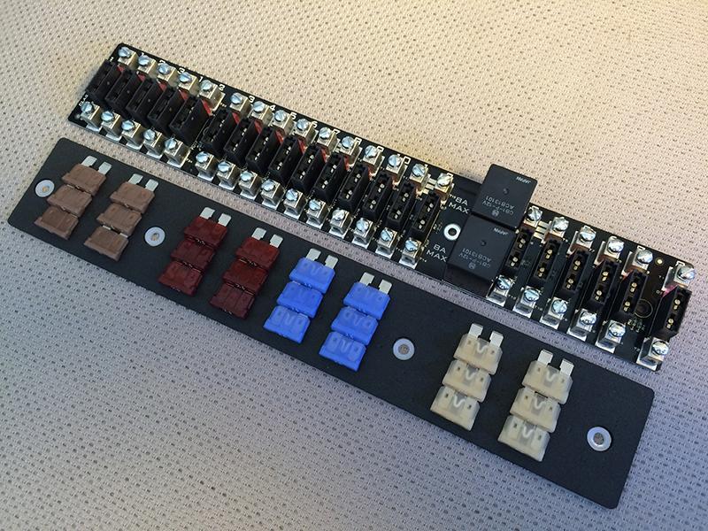
5 terminal on Issue 1.3 panels at this stage but read the Additional Headlamp Feed section at the end of this document for information. 7. When you have completed the bottom row, remove the cable ties and pull the new panel away from the old fuses to access the six mounting screws for the original blocks. Set the screws to one side (you will be reusing them). The old fuse blocks are now just 'hanging' on the top row wiring. 8. Again, starting at the left hand end, transfer each top row wire across to the new panel. These are replicated on PCB of the new panel so do not need to be fitted. This time, you will be able to remove the three original blocks as you go along for improved access. Note: The (old) photo above shows two red wire links. These do not need to be fitted as all panels from Issue 1.2 onwards have onboard links. Links between terminals are marked clearly on the fuse panel with 3 white horizontal lines:

6 9. When you have finished the top row, have a cup of tea as the worst is over! 10. Insert the gasket behind the new panel. It has a correct way up so please note the screw hole orientation. 11. The new panel is mounted using four of the original mounting screws. The supplied nylon spacers must be fitted between the panel and the metalwork of the 'fuse box'. It can be helpful to 'stick' the spacers in place with some light grease to aid installation. 12. Screw the panel down to the metalwork. 13. Recheck every screw terminal for tightness. 14. Reconnect battery and check all electrical systems. Note: The original lid will fit over the new panel but the recess on the far right hand end may need enlarging but a few mm for a good fit.

7 Led Indicator function. Your new fuse panel features a red LED on each fuse way. These can serve two purposes. In normal operation, with fuses fitted, the LED will indicate a blown fuse. Note the LED will only be lit if the circuit feed is live. For example, if the fuel pump fuse has blown, the LED will only light when the fuel pump is being 'told' to run. For diagnostic purposes, the LED can be used to trace faults in the electrical systems of the car. Simply take the fuse out for the circuit you wish to test. For example, if you suspected your turn signal switch to be defective, remove that fuse and check for the LED illumination when the switch is operated.

8 Removal of an existing headlamp relay kit. If upgrading to the 911-FPR panel you should remove the existing relay kit before you start. Typically these kits have six connections and the relays are separate to the fuse panel. The colours for the wiring in these kits have changed over the years but usually they are: J West kit Sucro kit Function Red Red 12v (battery +) Black Black Ground (chassis / battery -) White White High beam feed from headlamp switch Yellow Yellow Low beam feed from headlamp switch White Blue High beam to headlamp (fuse 1) Yellow Blue Low beam to headlamp (fuse 3) Remove the battery negative terminal. Start by identifying the 12V and Ground wires and removing them. Remove all four wires from top and bottom fuses 1 and 3 on the right hand fuse block. The only wires remaining connected should be the two that have been spliced to the original headlamp switch feed wires. For an impact bumper car the original wires are white and yellow. remove the splice and reconnect the original white wire to fuse 1 and the yellow wire to fuse 3 on the right hand fuse block. Remove the relay kit from the car. You are now ready to start the installation as per the normal instructions.

9 Late model UK and Swedish Carrera 3.2 Some European cars from around 1987 model year are fitted with the M062 (Swedish) option. This provides a dimmed dipped headlamp beam when the light switch is pulled out one stop and the ignition is on. The idea was to provide a light brighter than the normal parking/sidelight bulbs but not as bright as the normal dipped beam. This was implemented by using a control unit that provided a separate feed to the dipped beam circuit. Interestingly, the reason for this feature was due to legislation that was put forward in Europe in the mid 80's. The legislation was subsequently scrapped. If you have an Issue 1.3 fuse panel or higher just make sure that the yellow/black wire is connected to fuse way 4 to the right of relay. That is all you need to do! Issue 1.2 fuse panels only If you have a 1.3 or later panel, please skip this section. If you have a white and a yellow/black wire in the following fuses, your car is fitted with this option as shown in the following photo.
10 The M062 control unit sends a signal on the yellow/black wire that can cause the relay to buzz on 911-FPR fuse panels up to and including versions 1.2. If you have this option, please disconnect the yellow/black wire (tape up the end) Since the control unit was designed as additional equipment, the removal of the yellow/black wire only removes the dim dipped 'feature' but normal operation of side and parking lights is still fully functional. You may, however, discover that your front parking/sidelight bulbs have not been working for many years but this fault was 'masked' by the control unit. If you ever wondered why pulling the light switch one stop with the ignition off only gave you tail lamps, now you know why! Cars with extra equipment The 911-FPR fuse panel takes power for the headlamps from the linked group of four 'always live' terminals at the left hand end of the panel - labelled The links are shown on the panel by the white horizontal bars. If you have an Issue 1.3 fuse panel, please read the Additional Headlamp feed section. The wiring on the majority of cars is capable of providing this extra current feed to the headlamps. If your car has been fitted with additional accessories (high power stereo equipment, heated seats/screens etc) the wiring may be near its current carrying capacity. This would show as reduced brightness headlamps when the accessories are on, particularly on 'full beam'. If you experience this, add an additional red feed wire direct from battery to any of the linked group of 4 'always live' terminals.

11 Additional Headlamp Feed. Issue 1.3 or higher fuse panels have an extra terminal marked 'H' for providing an extra feed wire to the headlamp circuit. This can allow the car to be upgraded to 100/80W bulbs. To perform this upgrade an additional feed wire (not supplied) can be fitted between the battery positive terminal and the 'H' Terminal on the fuse panel. Fitting the extra headlamp feed can help to spread the current load on cars with additional equipment, even though standard headlamps are fitted. If fitting upgraded headlamps it is essential to check the condition of the original Porsche wiring loom and connections to the headlamps. It is also highly recommended that the plastic headlamp connector is replaced with a ceramic type. The feed wire to the 'H' Terminal should be rated 32A. The wiring from fuse panel to headlamps should be rated 16A for a comfortable safety margin.
12 Troubleshooting Miswiring All Classic Retrofit kits are electrically tested before shipping. The most likely source of problems will be failure to connect the wires as per original. It is easy to miss a wire on the bottom row as they are hard to see. It is also easy to forget to skip a gap as not all terminals are occupied on the bottom row. Refer back to your reference photos and see if you can spot a mistake 'Foreign' wires The second most common cause of odd behaviour is likely to be the hornet's nest effect. That is, you've been fiddling around with wires that haven't been moved in many years. Perhaps you have found or disturbed 'mystery' wires. Over the years, your car has met a few auto electricians for stereo, alarm and other accessory installations. It isn't surprising to find that there are odd wires, splices and -horror- 'scotch locks' in the wiring loom. Identifying rogue wires is actually pretty easy. All the original Porsche wires that terminate at the fuse panel have ferrules (small crimps) on the copper part of the wire. If the wire does not have this it is either a 'foreign' wire or an original wire that has been cut. It is good to trace these wires and see if they are actually doing anything. Remove if not. No Headlamps, no relay click? Grounding If you cannot hear the relays click when you turn the lights on, it is almost certainly due to bad grounding. The 911-FPR relays use the mounting screw to the left of the relays as a ground. It is important that the screw has good electrical contact with the new fuse panel and is properly secured into the metalwork behind. The black metal panel itself should be grounded to the chassis via the top wing/fender screws. If you have a meter then the you should be able to 'buzz' between the mounting screw and chassis (disconnect battery first). If the metalwork or the car has been repainted, sometimes the electrical connection is not made at the wing/fender screws. There are two ways to remedy this: 1) Loosen the wing/fender screw and take the paint back to bare metal beneath it. 2) Try adding a extra ground wire to the black metal bracket. The most convenient point to do this is on the far left of the metal bracket. There is a mounting screw and just to the left on the inner wing is an earthing stud. Connect the two points shown on the picture overpage.

13 Connect the two points shown in the picture to earth the metal bracket. This is a low current connection requiring standard gauge automotive wire similar to that shown on the brown wire in the picture. Disclaimer This equipment must be installed by an auto electrician or persons of equivalent level of competence. Failure to follow the installation procedure can result in damage to the vehicle, its wiring harness and injury. The 911-FPR fuse panel has been designed and engineered to the best of our best capabilities. It has been bench and road tested in a 1982 Porsche 911 SC. At the time of writing, fuse panels have been fitted to over vehicles spanning 1974 to The fuse panel will in most cases be a straight swap for the existing bullet fuse blocks in the car. On rare occasions, however, non-standard wiring or extra equipment may mean that the fuse panel may not function as a plug and play item. If you are worried about this please a photo of your panel to info@classicretrofit.com before commencing installment. Classic Retrofit will not accept liability for damage to wiring looms or the vehicle in which the fuse panel is installed. We will not accept any liability for injury of any kind caused by installation of our equipment.
CLASSIC UPDATE WIRING KIT
 by Randy Irwin 1955-57 CLASSIC UPDATE WIRING KIT Randy Irwin - Technical Writer Randy has been involved in the Chevy parts business for over 25 years. He is a wizard at creating, making and modifying custom
X-Charge Fitting Instructions
 X-Eng is a division of Foundry 4x4 Limited The Old Bakery, Rear of Vale Terrace, Tredegar, Gwent. NP22 4HT X-Charge Fitting Instructions Thank you for choosing to buy an X-Charge! Vehicle newer than 1995
REPAIR for: Sidelamp Bulb(s) Faulty, Left Tail Lamp Faulty, Right Tail Lamp Faulty, Directional Indicator Faulty, Left Hand Stop Bulb Faulty
 Faulty, Left Tail Lamp Faulty, Right Tail Lamp Faulty, Directional Indicator Faulty, Left Hand Stop Bulb Faulty") REPAIR for: Sidelamp Bulb(s) Faulty, Left Tail Lamp Faulty, Right Tail Lamp Faulty, Directional Indicator Faulty, Left Hand Stop Bulb Faulty DIFFICULTY LEVEL: ***** Drilling, Wire Crimping, Tight Spaces,
REPAIR for: Sidelamp Bulb(s) Faulty, Left Tail Lamp Faulty, Right Tail Lamp Faulty, Directional Indicator Faulty, Left Hand Stop Bulb Faulty DIFFICULTY LEVEL: ***** Drilling, Wire Crimping, Tight Spaces,
Installation Directions for FINGER STICK and Blocker Plate
 Installation Directions for FINGER STICK and Blocker Plate What is a Finger Stick? A Finger Stick is a simple circuit that modifies the MAF signal on LLY and LBZ engines (not LB7 engines) to expected levels
C15C C15C. Page 1 of 20
 2 x Lid Front Hinge 1135 8 x M8 Bolt 8 x M8 Washer (3mm Thick) 4 x M6 Large washers 4 x M6 Spring washers 4 x M6 x 40mm Bolts 6 x M6 20mm Bolts 6 x M6 Washers 20 x Screws 2 x Lid mount gas strut bracket
KENSUN HID AUTOMOTIVE HEAD LAMP CONVERSION KIT INSTALLATION MANUAL
 1 KENSUN HID AUTOMOTIVE HEAD LAMP CONVERSION KIT INSTALLATION MANUAL 2 CONTENTS A. Before Installing B. Installing the Bulbs C. Installing the Ballasts D. For Bi Xenon Only: Installing the Relay Harness
Instructions (V ) Type 3 - Hi/Low kit HID Low beam and H3, halogen, for High beam
 Type 3 - Hi/Low kit HID Low beam and H3, halogen, for High beam") Instructions (V5 04.23.2012) Type 3 - Hi/Low kit HID Low beam and H3, halogen, for High beam H4 (9003), H13 (9008), 9004, 9007 These bulbs have a HID Low beam and Halogen Bulb for High beam. Items included
Instructions (V5 04.23.2012) Type 3 - Hi/Low kit HID Low beam and H3, halogen, for High beam H4 (9003), H13 (9008), 9004, 9007 These bulbs have a HID Low beam and Halogen Bulb for High beam. Items included
UNIVERSAL GAUGE WIRE HARNESS
 2650-1797-00 UNIVERSAL GAUGE WIRE HARNESS For Installing Auto Meter Electric Speedometer, Tachometer, And Short Sweep Electric Oil Pressure, Water Temperature, Fuel Level, and Volt Meter Gauges. This harness
Detroit Speed, Inc. Electric Headlight Door Kit Corvette P/N: &
 Detroit Speed, Inc. Electric Headlight Door Kit 1968-82 Corvette P/N: 122006 & 122007 The Detroit Speed Inc. Electric Headlight Door Kit replaces the stock vacuum actuated system on all 1968-82 Corvettes.
Loopfrarne Alternator Kit Instructions
 Loopfrarne Alternator Kit Instructions Introduction First, thanks for purchasing this kit. We hope it will help make your V700, Ambassador, or Eldorado an even better "practical classic" than it already
TD77-2 and ULB42-TD-2 TRAFFIC DIRECTOR CONTROL BOXES
 TD77-2 and ULB42-TD-2 TRAFFIC DIRECTOR CONTROL BOXES Important: This product is used to direct traffic. Improper use may result in vehicular collision, personal injury and/or death. Star Headlight & Lantern
Installing Ignition Coil relay
 Installing Ignition Coil relay Above is a schematic diagram of the coil relay modification. All it really does is, it uses the existing 12 Volt positive that normally powers the coils, to power a relay,
Shotgun Double Barrel HPFP install guide
 Shotgun Double Barrel HPFP install guide Thank you for your purchase of the VTT Shotgun Double Barrel HPFP upgrade! First thing to do when you open your box is to make sure all parts are in their respective
Detroit Speed, Inc. Electric Headlight Door Kit Corvette P/N: &
 Detroit Speed, Inc. Electric Headlight Door Kit 1968-82 Corvette P/N: 122006 & 122007 The Detroit Speed Inc. Electric Headlight Door Kit replaces the stock vacuum actuated system on all 1968-82 Corvettes.
Tailgate Light Bar Installation by Flopster Feb 2015
 Tailgate Light Bar Installation by Flopster843 23 Feb 2015 If you ever looked at the rear of a 3rd generation Dodge Ram dually pickup truck, you'll notice that there is a light bar with 3 red marker lights
Stand Alone Fog Lights Installation Instructions
 Tools Required: 1. Trim Removal tool or protected flat screwdriver 2. #2 Phillips Screwdriver 3. 10mm socket 4. 10mm wrench 5. 8mm or 5/16 socket 6. Adjustable Pliers 7. Electrical Tape WARNING!!! Disconnect
Mahindra Pikup (2009 Production Onwards)
") Mahindra Pikup (009 Production Onwards) Steel Bull Bar INSTALLATION INSTRUCTIONS Accessory Part No. BBAR07 Installation Time: 60min Approx Bull Bar Weight: 60KG! Important: Please read each step of these
Mahindra Pikup (009 Production Onwards) Steel Bull Bar INSTALLATION INSTRUCTIONS Accessory Part No. BBAR07 Installation Time: 60min Approx Bull Bar Weight: 60KG! Important: Please read each step of these
BX8848 Installation Instructions 4 Diode Wiring Kit For Motorhomes With Red Tail Lights
 For Motorhomes With Red Tail Lights WARNG: Incorrect wiring may result in blown fuses, damaged wiring, fire, or bodily injury. Blue Ox recommends installation of this kit by a trained professional. Blue
Tri-Spark Ignition System Installation Triple Cylinder TRI-0001
 Tri-Spark Ignition System Installation Triple Cylinder TRI-0001 There are potentially lethal high voltages produced at the ignition coils and spark plugs, therefore every precaution must be taken to prevent
FITTING KIT No s : BULL BAR WINCH ( P/No ) BULL BAR NON WINCH ( P/No )
 BULL BAR NON WINCH ( P/No )") ARB WINCH / NON WINCH BULL BAR TO SUIT LANDROVER DISCOVERY 2003 ONWARD. FITTING KIT No s :- 617 1793 BULL BAR WINCH ( P/No 343 2120 ) 617 1794 BULL BAR NON WINCH ( P/No 323 2120 ) WARNING FOR VEHICLES
ARB WINCH / NON WINCH BULL BAR TO SUIT LANDROVER DISCOVERY 2003 ONWARD. FITTING KIT No s :- 617 1793 BULL BAR WINCH ( P/No 343 2120 ) 617 1794 BULL BAR NON WINCH ( P/No 323 2120 ) WARNING FOR VEHICLES
SECTION M. ELECTRICAL. Section Description Page No.
 SECTION M. ELECTRICAL. Section Description Page No. M.1 General Page 2 M.2 Alternator Page 2 M.3 Battery Page 7 M.4 Hazard Warning System Page 7 M.5 Brake Fail Warning System Page 8 M.6 Seat Belt Warning
Turn Signal Kit Installation Instructions for Model A Fords & Other Antique Vehicles
 Turn Signal Kit Installation Instructions for Model A Fords & Other Antique Vehicles Lifetime Technical Support support@logolites.com 770-476-7322 www.logolites.com Manual 100-0005N Thank you for purchasing
Replacing a Load Cell in the 400 Series Force Plate
 Replacing a Load Cell in the 400 Series Force Plate Determining which load cell is faulty You will first need to determine which load cell is at fault. To do this you will need the XPV7 diagnostic software.
Installation Guide and User s Manual
 Installation Guide and User s Manual Version 1 Table of Contents 1. Introduction...1 1.1 Notes and warnings...1 2. Installation/Setup...2 2.1 LCD monitor...2 2.2 Monitor inputs...2 3. Monitor wiring harness...3
B29048, B29049, B29050, B29051, B29053, B
 May 1, 2011 Lit. No. 48266, Rev. 05 B29048, B29049, B29050, B29051, B29053, B29400-5 HARNESS KIT 3-PORT ISOLATION MODULE LIGHT SYSTEM w/2-plug SYSTEM HARNESSES Installation Instructions Read this document
HID XENON. [I n s t a l l a t i o n G u i d e ] H E A D L I G H T S. Method of installing the bulb and ballast.
![HID XENON. [I n s t a l l a t i o n G u i d e ] H E A D L I G H T S. Method of installing the bulb and ballast.](/thumbs/76/74317385.jpg "HID XENON. [I n s t a l l a t i o n G u i d e ] H E A D L I G H T S. Method of installing the bulb and ballast.") HID XENON H E A D L I G H T S [I n s t a l l a t i o n G u i d e ] Please read the installation guide carefully before removing original car lighting from the vehicle. Please read through the entire installation
HID XENON H E A D L I G H T S [I n s t a l l a t i o n G u i d e ] Please read the installation guide carefully before removing original car lighting from the vehicle. Please read through the entire installation
Connecting the rear fog light on the A4 Jetta, while keeping the 5 Light Mod
 Connecting the rear fog light on the A4 Jetta, while keeping the 5 Light Mod DISCLAIMER: I'm human and make mistakes. If you spot one in this how to, tell me and I'll fix it This was done on my 99.5 Jetta.
29048, 29049, 29050, 29051, 29052, 29053, 29054,
 April 15, 2014 Lit. No. 29225, Rev. 11 29048, 29049, 29050, 29051, 29052, 29053, 29054, 29400 5 HARNESS KIT 3 PORT ISOLATION MODULE LIGHT SYSTEM w/2 PLUG SYSTEM HARNESSES Installation Instructions Read
Type 1 - Single filament HID kit
 Instructions (V.4 01.23.2012) Type 1 - Single filament HID kit H1, H3, H7, H8, H9, H10 (9140,9145), H11, H12 (9040,9045,9055), 5202 (9009,H16), 880, 9005, 9006 These bulbs are used for low beam, high beam
Wiring checks below assume the vehicle is in reverse, secured so it won't roll, and key is on so backup lights are illuminated:
 Reverse Lockout Troubleshooting The way that the backup solenoid works is: When the backup lights are lit on your tow vehicle, 12 volt power should come down the blue wire through the trailer connector
Depress each tab as you pull the bezel off. The bezels are tight. L.H. shown.
 2013-2014 Ford Mustang V6 & Boss 302 Lower Valance Fog Light Kit Parts List: Quantity: Tool List: Fog light & bulb with bracket 2 Flat head & Phillips screwdriver Black bezels 2 Ratchet & Socket set OR
FITTING OIL TEMP AND PRESSURE GUAGES
 FITTING OIL TEMP AND PRESSURE GUAGES this guide is of reference to fitting an oil temp and pressure sender/ sensor into a sandwich plate- not the sump plug temp sensor (although it wouldn't be much different
Ford Mustang GT-Style Fog Light Kit Parts List: Quantity: Tool List:
 2013-2014 Ford Mustang GT-Style Fog Light Kit Parts List: Quantity: Tool List: Fog light (Left& Right) 2 Flat head & Phillips screwdriver Upper grille with surround 1 Ratchet & Socket set OR Lower grille
CARM INTERNATIONAL TOWING MODULES
 CARM INTERNATIONAL TOWING MODULES (TA100/200 Instructions Revision = 1) Each Towing Module (if ordered with Loom Pack) is shipped with: A/ These instructions B/ 1 x Towing Control Module C/ 1 x high current
PN CHEVY TRI-FIVE. Kit Contents: Four panel Sequential LED Taillight kit installation guide
 Four panel Sequential LED Taillight kit installation guide Kit Contents: 2 tail light LED panels 2 tail light turn signal LED panels 1 rubber boot/sleeve kit 1 power wire with t-tap 1 driver side LED harness,
Starter Removal and Installation Instructions
 er Removal and Installation Instructions CAUTION: Always use care when working on your vehicle! Do NOT disconnect any electrical cables or wiring while the engine is running! WARNING: Before starting work,
jegs.com
 Contents Wiring Harness w/ Fuse Panel Installation Instructions Turn Signal Plug w/ Terminals 2 Headlight Plugs 3/4 Grommet 10 ¼ Terminals 4 Ring Terminals 10 Wire Ties Fusible Link 2 Screws & Nuts 2 Plastic
Model A Ford Lighting Upgrades. How to get more light without doing permanent alterations.
 Model A Ford Lighting Upgrades How to get more light without doing permanent alterations. How to improve performance Install more powerful bulbs in lights. Recondition reflectors. Clean electrical connections.
ULTRA TEAM TABLE OF CONTENTS I. INTRODUCTION
 JACOBS "i.c.e. PAK" -. (import Car Energy PAK) ULTRA TEAM INSTALLATION INSTRUCTIONS LEGAL FOR INSTALLATION IN ALL 50 STATES PER CARB EO #D-19-32 NOTE TO INSTALLER:' Before starting installation, read this
Rostra Electronic Cruise Control Install On a Stratoliner or Roadliner
 Rostra Electronic Cruise Control Install On a Stratoliner or Roadliner MATERIALS LIST: 1 - Rostra Part # 250-1223 (www.brandondist.com/products/cruise1223.htm) 1 - Signal Splitter part # 250-4369 1 - Engagement
Improvements to Window Lifts on Rolls-Royce and Bentley Cars, 1972 to 1989
 C SCBZSOTO9HCH20037, 1987 Bentley Turbo R SBH13247, 1972 Bentley T-Series Improvements to Window Lifts on Rolls-Royce and Bentley Cars, 1972 to 1989 SY (Silver Shadow Series Cars) Chassis 13754 to SZ (Silver
750 Paso Wiring Upgrade
 750 Paso Wiring Upgrade Supplies required: 2 Bosch 30A/12V Relays # #0 332 209 150 (with mounting tab) 1 30 Amp fuse holder 1 10 Amp fuse holder 12 inches of brown 12 gauge wire 60 inches of red 14 gauge
TREE ASSEMBLY INSTRUCTIONS
 TREE ASSEMBLY INSTRUCTIONS The Oldest Family Name for Christmas Trees in America SAVE THESE INSTRUCTIONS! - 1 - Table of Contents 1. Important Safety Notes Page 3 2. Attention Page 4 3. Getting Started
29048, 29049, 29050, 29051, 29052, 20953, 29054,
 July 15, 2008 Lit. No. 29225, Rev. 06 29048, 29049, 29050, 29051, 29052, 20953, 29054, 29400-2 HARNESS KIT 3-PORT ISOLATION MODULE LIGHT SYSTEM w/2-plug SYSTEM HARNESSES Installation Instructions Read
Main Relay. Fixing your PGM-Fi Main Relay.
 Main Relay Fixing your PGM-Fi Main Relay. Symptoms Problems starting the car, usually after a short run (when the interior is warm), though in bad cases the car may fail to start at any time. A classic
MKVI Jetta Fog Light Kit
 MKVI Jetta Fog Light Kit Part Number VW Jetta Fog Light Installation This tutorial is provided as a courtesy by ECS Tuning. Proper service and repair procedures are vital to the safe, reliable operation
Fitting instructions for Lynx R Fairing CRF 250L
 Fitting instructions for Lynx R Fairing CRF 250L Thank you for purchasing the Lynx fairing. We hope the design features will extend the enjoyment of your CRF. Parts List 1 x Fairing and screen with two
TTR225/250 DUAL S PORT K IT I NSTALLATION I NSTRUCTIONS
 TTR225/250 DUAL S PORT K IT I NSTALLATION I NSTRUCTIONS KIT CONTENTS Inspect Your Kit Your kit will include the following items A. TTR225/250 Instructions and Wiring Diagrams Read through the entire instruction
Z8 Engine Start Button Install for the BMW E46 3 Series
 Z8 Engine Start Button Install for the BMW E46 3 Series This write up is a specific installation of a Z8 engine start button on the E46, but it can be used as a general guide for an engine start button
Validator and Control Board Update Instructions for BC1
 Validator and Control Board Update Instructions for BC1 Installation Overview The update kit for the Rowe BC1 enables the changer to interface with a Mars AE/VN 120-volt validator. The validator determines
SB SWITCH CONTROL BOX
 Carson Manufacturing Co., Inc. 5451 North Rural Street Indianapolis, IN 462 Phone: (888) 577-6877 Fax: (317) 254-2667 www.carsonsirens.com SB-008-25 SWITCH CONTROL BOX INSTALLATION AND OPERATING INSTRUCTIONS
Instructions (V ) Type 2-Hi/Low, Motorized HID kit H4-M2 (9003), H13-M2 (9008), 9004-M2, 9007-M2
 Type 2-Hi/Low, Motorized HID kit H4-M2 (9003), H13-M2 (9008), 9004-M2, 9007-M2") Instructions (V5 04.23.2012) Type 2-Hi/Low, Motorized HID kit H4-M2 (9003), H13-M2 (9008), 9004-M2, 9007-M2 Items included; 2x Hi/Low, Motorized bulbs 2x 35-45W CAN BUS Digital Ballasts, 1x Hi/Low, Motorized
Instructions (V5 04.23.2012) Type 2-Hi/Low, Motorized HID kit H4-M2 (9003), H13-M2 (9008), 9004-M2, 9007-M2 Items included; 2x Hi/Low, Motorized bulbs 2x 35-45W CAN BUS Digital Ballasts, 1x Hi/Low, Motorized
MGB V8 Roadster restoration project Report 130
 1 st April 2017. I promise I won t add in any April Fool jokes into this report. But of course anything is possible! Yesterday, I only managed an hour on the MG, as I helped Jaymic with their stock take.
Installation Instructions Jeep CJ-7
 Retrofit Steering Column Installation Instructions 1976-86 Jeep CJ-7 For Part # s 1520800010, 152800020, 1520800051 www.ididitinc.com 610 S. Maumee St., Tecumseh, MI 49286 (517) 424-0577 (517) 424-7293
Congratulations. You ve just purchased the most advanced flasher available on the market today. This
 Congratulations. You ve just purchased the most advanced flasher available on the market today. This solid-state module is designed to interface with Ford s shutter system in each headlight assembly. When
 Page 1 of 14 This install requires work on your supplemental restraint system and could cause injury or damage to your car. If you are not comfortable performing the steps detailed here then do not attempt
HOW - TO WIRING & LIGHTING
 HOW - TO WIRING & LIGHTING Tool And Material Checklist Test Light Service Manual Penetrating Oil Long-Nose Pliers T-Square or Right Angle Screwdriver Black Electrical Tape Fuses Fuse Puller Cloth or Paper
INSTALLATION INSTRUCTIONS FUEL SURGE TANK KIT
 INSTALLATION INSTRUCTIONS FUEL SURGE TANK KIT BMW E46 3-Series, Excl Convertible Document: 19-0056 Support: info@radiumauto.com Relieve fuel pressure in vehicle before beginingthe installation. Disconnect
Installation MKIV Headlight Housings with Fog Lamps (Procedures apply to both MKIV Jetta and Golf)
") Page 1 This tutorial is provided as a courtesy by ECS Tuning. Service Procedure Installation Proper service and repair procedures are vital to the safe, reliable operation of all motor vehicles as well
Page 1 This tutorial is provided as a courtesy by ECS Tuning. Service Procedure Installation Proper service and repair procedures are vital to the safe, reliable operation of all motor vehicles as well
Detroit Speed, Inc. RS Electric Headlight Door Kit 1969 Camaro P/N: (3)
") Detroit Speed, Inc. RS Electric Headlight Door Kit 1969 Camaro P/N: 122001 (3) (1) (2) (5) (4) Figure 1 Item QTY Description 1 1 LH actuator w/bracket and linkage 2 1 RH actuator w/bracket and linkage
Detroit Speed, Inc. RS Electric Headlight Door Kit 1969 Camaro P/N: 122001 (3) (1) (2) (5) (4) Figure 1 Item QTY Description 1 1 LH actuator w/bracket and linkage 2 1 RH actuator w/bracket and linkage
8436, 8437, 8438, 8439, 8442, 27480, 27780, 28028, & ISOLATION MODULE ELECTRICAL SYSTEM
 September 11, 2003 Lit. No. 27808 8436, 8437, 8438, 8439, 8442, 27480, 27780, 28028, & 28400 ISOLATION MODULE ELECTRICAL SYSTEM Installation Instructions Read this document before installing the snowplow.
Amp & Speaker Upgrade Install Instructions for Batwing Fairing
 Amp & Speaker Upgrade Install Instructions for Batwing Fairing Tools Needed: 1/2 inch Socket Wire Cutters 7/16 inch Socket Wire Strippers 10 mm Socket Phillips Screwdriver 1/2 inch Ratchet Wrench T25 Torx
Arlo Power Distribution Board Kit (#28996)
") Web Site: www.parallax.com Forums: forums.parallax.com Sales: sales@parallax.com Technical: support@parallax.com Office: (916) 624-8333 Fax: (916) 624-8003 Sales: (888) 512-1024 Tech Support: (888) 997-8267
Web Site: www.parallax.com Forums: forums.parallax.com Sales: sales@parallax.com Technical: support@parallax.com Office: (916) 624-8333 Fax: (916) 624-8003 Sales: (888) 512-1024 Tech Support: (888) 997-8267
Owner s Manual Electronic Harness Controller P/N ASM4250
 Owner s Manual Electronic Harness Controller P/N ASM4250 Thunder Heart Performance Corporation MANUAL P/N EI4250 120 Industrial Drive Revision 6/3/04 White House, TN 37188 www.thunder-heart.com TABLE
Tip: and Orient Express LED Light Upgrade Date: Correction
 Hi All, I have since inherited my friend Rudolf s 42755 Orient Express with the extra 42760 car set and wanted to complete the LED light upgrade as we had planned. Side view of the Restaurant car with
TIP SHEET T0937. Installation Tips For RS00/PS00 + ADS-TBSL-PL + SPDT
 Installation Tips For RS00/PS00 + ADS-TBSL-PL + SPDT TIP SHEET T0937 Thank you for purchasing your remote start from MyPushcart.com - an industry leader in providing remote starts to do-it-yourself installers
PN R CHEVY CAMARO w/reverse Two panel Sequential LED Taillight kit installation guide. Kit Contents:
 Two panel Sequential LED Taillight kit installation guide Kit Contents: 2 LED panels 4 rubber grommets 1 power wire with t-tap 1 driver side LED harness, 24 1 passenger side LED harness, 48 2 LED extension
HOW-TO: Pimp your glowplug wiring
 HOW-TO: Pimp your glowplug wiring Contributed by Vince Waldon Tuesday, 30 September 2008 Last Updated Friday, 27 November 2009 vincewaldon.com var gajshost = (("https:" == document.location.protocol)?
Fitting instructions for the Petrol power amplifier
 Wayside Garage Holt Road, Horsford Norwich Norfolk NR10 3EE Tel Int. + 44 (0)1603 891209 Fax 890330 Web Site www.v8engines.com VAT NO: 373 2330 72 Partners C T Crane & R.P.I. International Ltd Fitting
BXD Battery Disconnect
 INSTALLATION MANUAL BXD Battery Disconnect Installation Manual BATTERY DISCONNECTS provides a simple and safe means of disconnecting the coach and chassis battery(s) of an RV. With just the touch of a
INSTALLATION INSTRUCTIONS
 INSTALLATION INSTRUCTIONS FUEL SURGE TANK INSTALLATION KIT 1999-2006 BMW E46 COUPE Document# 19-0056 Support: info@radiumauto.com Note: This kit was designed for a standard single pump Radium Engineering
INSTALLATION MANUAL STEP SLIDER BD-SS-200-JK4. Made in the USA. Front Bracket Middle Bracket Rear Bracket. Tools Required
 Made in the USA INSTALLATION MANUAL STEP SLIDER BD-SS-200-JK4 Description Quantity Electric Step Slider (Pair) 2 Front Bracket Middle Bracket Rear Bracket Bump stop plate with VHB backing 2 Wiring harness
Retro it Steering Column
 Retro it Steering Column INSTALLATION INSTRUCTIONS for 1976-86 CJ5 & CJ7 FOR PART NUMBER S: 1520800010, 1520800020, 1520800051, 1526800010, 1526800020, 1526800051 S I NCE 1986 Instruction # 8000000010
LightSaver. Installation instructions, Classic GMT-800 GM truck/suv. By: BT DieselWorks, LLC. 12/2012
 LightSaver Installation instructions, 2001-2002 Classic GMT-800 GM truck/suv By: BT DieselWorks, LLC. 12/2012 First of all, thank-you for purchasing the BT DieselWorks LightSaver smart headlight control
2010 Toyota Prius model II Head Unit Upgrade
 2010 Toyota Prius model II Head Unit Upgrade Monday, December 21, 2009 Disclaimer: Use this document and its contents at your own risk. Forward: Huge thanks to those members on Priuschat.com that forged
JBA Cat4ward Shorty Header Install (05-10 Mustang GT and Bullitt)
") JBA Cat4ward Shorty Header Install (05-10 Mustang GT and 08-09 Bullitt) Installation Time: 6-8 Hours (Depending on Tools and Help) Tools Required: 8mm Socket 10 mm Socket 13mm Socket 15mm Deep Socket Ratchet
JBA Cat4ward Shorty Header Install (05-10 Mustang GT and 08-09 Bullitt) Installation Time: 6-8 Hours (Depending on Tools and Help) Tools Required: 8mm Socket 10 mm Socket 13mm Socket 15mm Deep Socket Ratchet
Trail Rocker Installation Instructions
 Trail Rocker Installation Instructions Manual #90580 For Installing Painless Part Numbers: 57000 and 57001 Painless Performance Products recommends you, the installer, read this installation manual from
PIL0478 ISSUE 01/ 07/16
 ISSUE 01/ 07/16 PIL0478 ZAFIR G9 CEILING FITTING PIL0478 ISSUE 01/ 07/16 PART C PART E PART 21 SELV 1 1.B 1 3.1 3.3 3.4 3.5 3.6, 3.8 3.10 3.12 3.14 3.16 3.17 3.18 3.19 3.19 ATTENTION! THE TABLE BELOW
Installation of Halo CCFL Rings edited by
 Installation of Halo CCFL Rings edited by www.motorcyclehidlights.com Please use the below installation as an example for your project. Installation is done on a CBR600 however the same procedure will
MOTOALLIANCE WINCH MOUNT
 , / 1-866-527-7637 www.motoalliance.com MOTOALLIANCE WINCH MOUNT Polaris RZR Thank you for purchasing our MotoAlliance winch mount(s). You now own a premium custom winch mount to allow you to use your
LUCAS HEADLAMP SWITCH - PR18/4B
 LUCAS HEADLAMP SWITCH - PR18/4B By the mid-fifties Miller had lost considerable ground to Lucas in the competition for the British motorcycle market and Vincents switched to Lucas when the Series D machines
*Some speedometers have these additional electronic connections. If yours does, then remove the smaller slotted screws shown.
 www.odometergears.com 1981-1985 240 Cable-Driven Speedometers (NOT for 1986 and later electronic units) http://www.davebarton.com/240-odometer-repair.html For this set of instructions below, I will not
Detroit Speed, Inc. RS Electric Headlight Door Kit 1968 Camaro P/N: (3)
") Detroit Speed, Inc. RS Electric Headlight Door Kit 1968 Camaro P/N: 122002 (3) (1) (2) (5) (4) Figure 1 Item QTY Description 1 1 LH Actuator w/bracket and Linkage 2 1 RH Actuator w/bracket and Linkage
Detroit Speed, Inc. RS Electric Headlight Door Kit 1968 Camaro P/N: 122002 (3) (1) (2) (5) (4) Figure 1 Item QTY Description 1 1 LH Actuator w/bracket and Linkage 2 1 RH Actuator w/bracket and Linkage
Detroit Speed, Inc. Selecta-Speed Wiper Kit Corvette P/N:
 Detroit Speed, Inc. Selecta-Speed Wiper Kit 1963-67 Corvette P/N: 121620 A downpour of rain will no longer hinder your ability to clearly see the road. The Detroit Speed Selecta-Speed Wiper Kit provides
INSTALLATION INSTRUCTIONS
 INSTALLATION INSTRUCTIONS FUEL PUMP HANGER FORD MUSTANG: 2011+ S197 AND S550 Support: info@radiumauto.com Document# 19-0161 WARNING: DO NOT EXPOSE WORK AREA TO ANY SPARKS OR FIRE. DO NOT SMOKE WHILE WORKING
Fanatec GT3RS V1 to GT3RS V2 Tutorial
 Fanatec GT3RS V1 to GT3RS V2 Tutorial by Roy Visser 1 How to update your Fanatec GT3RS V1 wheel to a GT3RS V2 wheel Welcome to this guided and detailed tutorial for upgrading your Fanatec GT3RS V1 wheel
Disconnect the battery power from the car.
 Adding a safety fuse to the ignition circuit of 1956 to 1962 Corvettes Part 1 is for 1958 to 1962. Part 2 is for 1956 to 1957 Rich Mozzetta and Dave Zuberer Part 1-1958 to 1962 Here is a way to add a fuse
2010 Toyota Prius Fog Light Retrofit
 2010 Toyota Prius Fog Light Retrofit A DIY prospective Last updated: Friday, December 25, 2009 *** Disclaimer Use this document and its contents at your own risk! *** Forward: This document was compiled
MAZDASPEED3 Intercooler Instructions
 MAZDASPEED3 Intercooler Instructions Congratulations on your purchase of the COBB Tuning Front Mount Intercooler System for your 2007-2009 Mazdaspeed3. The following instructions should assist you through
The gauges selected for my installation were the following: Part Application
 This write up documents the installation of Autometer Sport Comp II gauges into a 1971 Camaro with original full factory instrumentation. The Autometer gauges completely replace the original factory instrumentation,
INSTALLATION INSTRUCTIONS
 INSTALLATION INSTRUCTIONS FUEL SURGE TANK INSTALLATION KIT 1999-2006 BMW E46 COUPE Document# 19-0056 Support: info@radiumauto.com Note: This kit wasn t designed for a FST-R, but can be accomplished. 1.
Installing the STS-4CH Dodge Challenger Sequential Turn Signal System
 Installing the STS-4CH 2008-2010 Dodge Challenger Sequential Turn Signal System The STS-4CH is an exciting addition to your 2008-2010 Dodge Challenger. This Plug-N-Play system comes complete with pre-wired
INSTALLATION INSTRUCTIONS
 Rear Vision System Tailgate Emblem Camera Mirror Display 2009-Current Ford F-150 and 2010-Current Super Duty (Kit part number 1008-9527) Kit Contents: Mirror Tailgate Emblem Mount with Camera Interior
Installation Tips for your Remote Start system (for Toyota Camry & Prius C, ) Crimestopper RS0+ EVO-ALL T3468 rev#1.
 Crimestopper RS0+ EVO-ALL T3468 rev#1.") Installation Tips for your Remote Start system (for Toyota Camry & Prius C, 2012-2014) Crimestopper RS0+ EVO-ALL T3468 rev#1.1 1/22/2015 Thank you for purchasing your remote start from MyPushcart.com -
Installation Tips for your Remote Start system (for Toyota Camry & Prius C, 2012-2014) Crimestopper RS0+ EVO-ALL T3468 rev#1.1 1/22/2015 Thank you for purchasing your remote start from MyPushcart.com -
C FORD F250 / F L POWERSTROKE DIESEL WITH AUTOMATIC TRANSMISSIONS ONLY
 EXHAUST BRAKES C40019 1999-2003 FORD F250 / F350 7.3L POWERSTROKE DIESEL WITH AUTOMATIC TRANSMISSIONS ONLY Getting Started Thank you and congratulations on your purchase of a Pacbrake exhaust retarder.
Fabricating and Installing Headlight Relays. Mike Graham
 Fabricating and Installing Headlight Relays Mike Graham For some time I had been reading about the benefits of installing headlight relays. As I understand it, there are two principal benefits: the load
LV2000. revision 1.5. Low Voltage Power Supply Retrofit Kit for Wells-Gardner Color XY Monitor, model 19K6100. Installation Instructions ! WARNING!
 LV2000 revision 1.5 Low Voltage Power Supply Retrofit Kit for Wells-Gardner Color XY Monitor, model 19K6100 Installation Instructions! WARNING! To successfully install this kit requires that you have good
A. Welding Control Module. 2. Control Models WC.12RO & WC.24RO -- Location of Internal Indicators and Fuses
 IX. Trouble/Fault Diagnosis (after successful installation) The ZENA mobile welding system has been designed to be very simple to use. In addition, no expense has been spared to insure that it is also
POWERED RUNNING BOARDS INSTALLATION MANUAL
 POWE RUNNING BOARDS INSTALLATION MANUAL Level of Difficulty Moderate Parts List 1 Driver / left running board* 1 Passenger / right running board* 4 Mounting bracket, standard 2 Mounting bracket, middle
Technical Installation Manual
 Lighting Step and Aisle Safety Lighting Technical Installation Manual 1 Contents Page 3 Tools required 4 Installation detail & planning 5 Adhesives, silicone & crimps 6 General cinema layout 7 Basic wiring