STAINLESS STEEL VALVES AND ACCESSORIES
|
|
|
- Sarah Kennedy
- 6 years ago
- Views:
Transcription


1 BULLETIN V Series V-316 STAINLESS STEEL VALVES AND ACCESSORIES


 The V-316")


, pilot")


 A -181DE :")

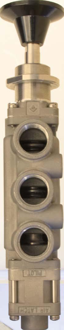
2 MODULAR CONCEPT Versa exercises diligence to assure that in formation contained in this catalog is correct, but does not accept responsibility for any errors or omissions. Versa also reserves the right to change or delete data or products at any time without prior notification. To be sure the data you require is correct, consult factory. VAG DE-XX-(specify voltage) The V-316 Valve Series provides a full range of control valves suited to the most demanding of applications. Ruggedly constructed, both internally and externally, of stainless steel, these valves are able to withstand the physical abuse of corrosive environments and controlled media. A modular design concept utilizing three basic sub-assemblies: a Body Assembly and two Actuator Assemblies (active or passive), simplifi es circuit planning while affording almost unlimited combination possibilities. Port sizes are 1/4 NPT, 3/8 NPT and 1/2 NPT in three-way (3/2, 3/3), and four-way (5/2 and 5/3) styles. Actuation types include manual (hand lever, palm button, latching detent & manual reset), pilot (pressure pilot, diaphragm pilot, air-latch pilot), and solenoid-pilot (including several approved hazardous service types). Solenoid-Pilot Actuator Manual Actuator G -XX Sub-Assembly Nr.: SA XX (specify voltage) A -181DE Sub-Assembly Nr.: CA DE Body Assembly 4522 Sub-Assembly Nr.: SA Spring Return Actuator S Sub-Assembly Nr.: SA Other functions can be easily accomplished as shown with these Pilot and Spring Return actuators. This Bulletin only gives the Actuator Sub-Assemblies and Body Sub-Assemblies. This gives the design engineer maximum versatility as these modules can be combined to complete valves with functions as needed. Pilot Actuator P Sub-Assembly Nr.: SA
3 TECHNICAL DATA MATERIALS: Metal Parts: 316 stainless steel (except solenoid parts, ask factory) conforms to NACE standard MR Hand Knob: plastic PRESSURES: Seals: FKM (Fluorocarbon) is standard. Exceptions: diaphragm-pilot seal is NBR (Buna N) or with suffix -31 Teflon coated Buna N; other seal materials are available. See TEMPERATURES/SEALS below. Valve type Pneumatic* VALVE BODY (inlet/system) Manual or Pilot Standard Seals Single Solenoid EXPilot (2-position) Standard Seals Double Solenoid EXPilot (2-position) Standard Seals Double Solenoid EXPilot (3-position) Standard Seals Single Solenoid INPilot (2-position) Standard Seals Double Solenoid INPilot (2-position) Standard Seals Double Solenoid INPilot (3-position) Standard Seals PILOT (signal) Some restrictions concerning maximum pressures may apply. See specific actuator. Pilot (2-position VSP or 3-position VJJ ) Pilot (2-position VPP ) Diaphragm (2-position VSW or 3-position VYY ) Diaphragm (2-position VSW or 3-position VYY ) w/suffix -31 Diaphragm (2-position VWW ) Diaphragm (2-position VWW ) w/suffix -31 Solenoid EXPilot (2-position VSG or 3-position VXX ) Solenoid EXPilot (2 position (VGG ) psi bar (Mpa = bar ) 10 Vacuum to 200 Vacuum to to to to to to to to to 50 5 to to to to to to to to to to to to to to 12 Notes: When application involves temperatures below freezing or when shifting intervals are relatively long, it is recommended that suffix -S be specified for valves with spring actuation. Minimum pilot pressure must be increased by 40%. Notes: The following suffixes include the use of suffix -S in all cases: -181AAE, -181CE, -181DE, -3358AE, -3358E. *Consult factory for hydraulic service. TEMPERATURES/SEALS: The table below lists suggested suffix options for various temperature ranges and/or types of service. For temperatures or conditions not listed, consult factory. Type of Service Temperature Range Intermittent Duty Service Continuous Duty Service (Medium/Ambient Temperature) AC or DC AC DC Coil Solenoid Plunger Coil Solenoid Plunger Coil Solenoid Plunger 150ºF to 200ºF (65ºC) (95ºC) 120ºF to 150ºF (50ºC) (65ºC) -10ºF to 120ºF (-23ºC) (50ºC) Suffix -HT Standard Suffix -3 (may be inclusive in other suffix options as it is in -HT) Suffix -3 (may be inclusive in other suffix options) Suffix -HT Standard Suffix -3 (may be inclusive in other suffix options as it is in -HT) Suffix -3 (may be inclusive in other suffix options) Standard Standard Standard Suffix -3 (may be inclusive in other suffix options) Suffix -HT Suffix -HT Standard Suffix -3 (may be inclusive in other suffix options as it is in -HT) Suffix -3 (may be inclusive in other suffix options as it is in -HT) Suffix -3 (may be inclusive in other suffix options) FLOW CALCULATION: Air Flow = f (p1-p2)(p2) (T)(SG) English Metric Air flow SCFM Nm 3 /h f = Conversion factor 22.5 Cv 30.8 Kv p1 = Upstream pressure p1 - p2 < 0.5 p2 p2 = Downstream pressure psi absolute bar absolute T = Temperature upstream absolute 460º + Fº 273º + Cº SG = Specific gravity FLOW: Note: 0.59 SCFM = 1 Nm 3 /h 14.5 psi = 1 bar Port Size of Valve Body For details see page 8.1 through 8.6 1/4 NPT 3/8 NPT 1/2 NPT Flow Diameter inch mm 3/ / / Flow Factor Cv Kv
4 TECHNICAL DATA ELECTRICAL: Solenoid-Pilot actuated V316 valves are available with a variety of different solenoids for both nonhazardous and hazardous locations. Basic details of these actuators are listed below. Dimensions, product numbers, and other details may be found on pages 5.1 through 5.6. For additional data consult factory. NON HAZARDOUS LOCATION SOLENOIDS Suffix Identification Protection Classification Area Classification and (Gas Grouping) Certification- (Conformance) -U General Purpose Indoor & Outdoor CSA NEMA 1, 2, 3 Ingress Protection -HC -U General Purpose Indoor & Outdoor CSA NEMA 4; IP65 per IEC 529 HAZARDOUS LOCATION SOLENOIDS Suffix Identification Protection Classification Area Classification and (Gas Grouping) Certification- (Conformance) Ingress Protection -XX Page 5.3 Hazardous Locations Class I, Division 2 (A & B) Class I, Division 1 (C & D) Class II, Division 1 (E, F, & G) UL CSA NEMA 7 & 9 -LB-XX Hazardous Locations Class I, Division 2 (A & B) Class I, Division 1 (C & D) Class II, Division 1 (E, F, & G) UL CSA NEMA 7 & 9 Page 5.4 -XN (d) Flameproof Zones 1 and 2 (IIB+H 2) Category 2G T4 ATEX IP66 Page 5.3 -LB-XN (d) Flameproof Zones 1 and 2 (IIB+H 2) Category 2G T6 ATEX IP66 Page 5.4 -XDAS or -XDAT Page 5.3 (d) Flameproof Zones 1 and 2 (IIC) Category 2G ATEX IP66 and IP67 -XMAA or -XMAE or -XMAF or -XMAG Page 5.5 (m) Encapsulation (e) Increased Safety Zones 1 and 2 (II) Category 2G ATEX IP66 and IP67 -XMFA or -XMFE or -XMFF or -XMFG Page 5.5 (m) Encapsulation (e) Increased Safety Zones 1 and 2 (II) Category 2G ATEX IP66 and IP67 -HC-XISC -HCC-XISC Hazardous Locations Class I, Groups (A, B, C & D) Class II, Groups (E, F & G) Class III, Division 1 Factory Mutual CSA NEMA 4 Page 5.6 -HC-XISX6 -HCC-XISX6 (ia) Intrinsic Safe Zones 0, 1 and 2 (IIC) Category 1G ATEX IP65 T6 Page 5.6 -XIFA or -XIFE or -XIFF (ib) Intrinsic Safe Zones 1 and 2 (IIB) Category 1G ATEX IP66 and IP67 Page
5 PRODUCT NUMBER COIL CODES: Complete product numbers require, when applicable, a coil code that represents the desired coil current type, frequency and voltage. The coil code takes the form shown below, with ratings and voltage substituted as required. Rating Code A = 60Hz frequency D = Direct Current (DC) E = 50Hz frequency Voltage (Power) All usual 50 Hz & 60 Hz AC (6W) All usual DC (7W) 24V60, 120V60, 240V60 (8.5W) 24V50, 110V50, 220V50 (8.5W) 12VDC, 24VDC, 48VDC (10.5W) Voltage (Indicated by three digits: as example, 24 volts = volts = 120.) Electrical Characteristics Class F epoxy molded coil (155ºC). Continuous duty 2 leads 24 (60 cm). Class F epoxy molded coil (155ºC), with 3 spade terminals and mini DIN socket with PG9 cable gland. Continuous duty. Miscellaneous Steel cover with 1/2 NPT conduit entry. Page 5.1 Page 5.1 Voltage (Power) All usual 50 Hz & 60 Hz AC (5.6W) All usual DC (7.2W) 12V60, 24V60, 48V60, 120V60, 240V60 (1.8W) 6VDC, 12VDC, 24VDC, 48VDC (1.8W) All usual 50 Hz & 60 Hz AC (5.6W) All usual DC (7.2W) 12V60, 24V60, 48V60, 120V60, 240V60 (1.8W) 6VDC, 12VDC, 24VDC, 48VDC (1.8W) 24V50, 230V50 (6W); 127V50 (10W) 24V60, 120V60, 240V60 (10W) 12VDC, 24VDC, 28VDC, 48VDC, 110VDC, 125VDC (10W) 24VDC (4W) (Consult factory for other voltage options) Electrical Characteristics Class F epoxy molded coil (155ºC). Continuous duty. 3 leads 24 (60 cm). Class F epoxy molded coil (155ºC). Continuous duty. 3 leads 24 (60 cm). Class F epoxy molded coil (155ºC). Continuous duty. 3 leads 24 (60 cm). Class F epoxy molded coil (155ºC). Continuous duty. 3 leads 24 (60 cm). Class F epoxy molded coil (155ºC). Continuous duty. Continuous duty. Coil & Rectifi er, including surge suppression, potted within housing. Miscellaneous Steel chromate coated coil housing with 1/2 NPT conduit entry. For stainless steel (182FM) coil housing add: (-ST) Steel chromate coated coil housing with 1/2 NPT conduit entry. For stainless steel (182FM ) coil housing add: (-ST) Maximum pilot pressure 120 psi (8 bar). 1.8W nominal power. Steel chromate coated coil housing with M20 x 1.5 conduit entry. Ground terminal on cover. For stainless steel (182FM) coil housing add: (-ST) Steel chromate coated coil housing with M20 x 1.5 conduit entry. Ground terminal on cover. For stainless steel (182FM) coil housing add: (-ST) Maximum pilot pressure 120 psi (8 bar) 1.8W nominal power. Stainless steel coil housing with internal Junction Box. Internal and external ground screw. M20 x 1.5 conduit entry: (-XDAS) 1/2 NPT conduit entry: (-XDAT) Thick wall epoxy coil housing with integral junction box. Internal ground terminal. M20 x 1.5 conduit entry: (-XMAA) Cable gland for 6-12 mm ø cable: (-XMAE) 1/2 NPT conduit entry with adapter: (-XMAF) Cable gland for 9-16 mm ø cable: (-XMAG) 24VDC (10W inrush, 2.6W holding) (Consult factory for other voltages) Continuous duty. Coil & Power Controller potted within housing. Thick wall epoxy coil housing with integral junction box. Internal ground terminal. M20 x 1.5 conduit entry: (-XMFA) Cable gland for 6-12 mm ø cable: (-XMFE) 1/2 NPT conduit entry with adapter: (-XMFF) Cable gland for 9-16 mm ø cable: (-XMFG) 24VDC system voltage prior to barrier (1.6 watt max.) 24VDC system voltage prior to barrier (1.6 watt max.) 24VDC (0.8W) (Consult factory for other voltages) Class F epoxy molded coil (155ºC). Continuous duty. Class F epoxy molded coil (155ºC). Continuous duty. Continuous duty. Coil and power controller potted within housing. Requires the use of an approved barrier or isolator. Maximum operating system voltage before barrier 28VDC. Maximum pilot pressure 115 psi (8 bar). 3 spade terminals & DIN connector with PG9 cable gland: (-HC) 1/2 NPT conduit entry: (-HCC) Requires the use of an approved barrier or isolator. Maximum operating system voltage before barrier 28VDC. Maximum pilot pressure 115 psi (8 bar). 3 spade terminals & DIN connector with PG9 cable gland: (-HC) 1/2 NPT conduit entry: (-HCC) Requires the use of an approved safety barrier or isolator. Thick wall epoxy coil housing and integral junction box. Internal ground terminal. M20 x 1.5 conduit entry: (-XIFA) Cable gland for 6-12 mm ø cable: (-XIFE) 1/2 NPT conduit entry with adapter: (-XIFF) 3.3
6 3.4 Each letter and digit in the product number of a Versa Valve has a signifi cant meaning, as explained below. Letters or numbers shown in black in the example below do not change. V S P Suffix Valve Series Series V-316 Valves Pneumatic Service (Nominal Pressure Range Vacuum to 200 psi (14 bar). Some restrictions apply. See specific actuators.) ACTUATING DEVICES At left end of At right end of valve valve when looking at inlet port of body* A B G I J L N P R S U Combination - or Special Actuator Spring centering (for 3 position manually operated valves) Solenoid-pilot Hand Button (for panel mounting) Pilot-Spring Centering Hand-Lever Non-return end-cap Pressure-Pilot Reverse Spring Return (spring pulls valve spool) Spring Return (spring pushes valve spool) 3-Position Detent (For 3 position manually operated valves) Function (also see Spool Details) 3* W Diaphragm-Pilot (low pressure-pilot) X Solenoid-Pilot Spring Centering (for 3 position solenoid pilot valves) Y Diaphragm-Pilot Spring Centering (for 3 position Diaphragm-Pilot valves) Z 2-Position Detent (for 2-position manually operated valves) *3-way NC function requires actuator device on right. 3-way NO function requires actuator device on left. Three-Way 3/2 or 3/3 4 Four-Way 5/2 or 5/3 7 Two Outlet (Diverter) 3/2 or 3/3 8 Two Inlet (Selector) 3/2 or 3/3 * Two-Way may be accomplished by plugging the exhaust port of three-way valve bodies Port Size 3 1/4 NPT 4 3/8 NPT 5 1/2 NPT BODY DETAILS Type of Body Sideported EXPilot 0 Body with threaded side-ports (for Manual, Pilot and EX- Pilot solenoid actuated valves) Sideported INPilot 2 Body with threaded side-ports and internal drilling to supply inlet pressure to INPilot act. of Solenoid-pilot Spool Details (flow pattern*) Three-Way 3/2 Valves 1 2 Norm. Closed Norm. Open 2 Two Outlet (See Function column for flow) 2 Two Inlet (See Function column for flow) Three-Way 3/3 Valves 3 4 For 3/3 Two-inlet or Two-outlet see pg. 8.3 Four-Way 5/2 Valves 2 Four-Way 5/3 Valves 3 4 *Left and Right Flow Diagrams indicate 2-position valve. Center Flow Diagram shows 3-position. For other Center Flow patterns, see pages 8.1 thru indicates that the basic construction material for valve parts is AISI 316 Stainless Steel (Conforms to NACE Standard MR-01-75) Suffix Detail numbers indicate modifications or variations of the basic Valve. When specifying, simply add the Suffix Details required in alphabetical and numerical following order. In this bulletin many Suffix Details are described. For more: see Suffix Detail Product Bulletin, or consult factory. Coil voltages are indicated here. For specific voltage, use coil code number listed on page 3.3. VERSA Series V-316 Valves consist of three Sub-Assemblies: one Body-Assembly and two Actuator-Assemblies, mounted at the LH side and the RH side of the Body. All the Actuators can be mounted at either side, are fully interchangeable and can be combined to suit the function desired. See Pages 4.1 through 8.6 for those Sub-Assemblies. SELECTOR CHART & PRODUCT NUMBERING
7 PILOT ACTUATORS* Prefi x Suffi x P (PRESSURE) PILOT SA PULL TYPE (PRESSURE) PILOT A and -PTP CA PTP (PRESSURE) PILOT with Threaded Vent port P and -107E SA E PUSH-PULL (PRESSURE) PILOT A and -PPP CA PPP J (PRESSURE) PILOT-SPRING CENTERED (for 3 position pilot operated valves) SA AIR LATCH (PRESSURE) PILOT hold function only A and -301E CA E AIR LATCH (PRESSURE) PILOT- PULL TYPE hold function only A and -301RE CA RE *For Pilot Pressure ranges see page
8 PILOT ACTUATORS* Prefi x Suffi x W Y DIAPHRAGM PILOT (for 2 position diaphragm pilot operated valves) SA For low pressure pilot signals DIAPHRAGM PILOT- SPRING CENTERED (for 3 position diaphragm pilot operated valves) For low pressure pilot signals SA NOTE: Diaphragm piston can be equipped with Tefl on coated Buna N U cup. Add suffi x -31 to complete valve number or sub-assembly number. PILOT-COMBINATION ACTUATORS* (PRESSURE) PILOT-TWO DETENT A and -150E CA E (PRESSURE) PILOT-REVERSE SPRING RETURN A and -159E CA E *For Pilot Pressure ranges see page
9 SOLENOID-PILOT ACTUATORS 2 Position GENERAL SERVICE (NONHAZARDOUS SERVICE) 24 Leads Third Wire Ground Supplied When Requested 1/2-14 NPT Conduit Conn Manual Override (Suffix - ME) VERSA UNF Adapter Option 1/8 NPT (Suffix - H2) Position 3 Position /8 NPT Pilot Inlet Port (on EXPilot Valves only) Height dimensions shown are for Nonhazardous solenoids. Dimension for Hazardous solenoids depend upon type of solenoid selected. Suffi x +options: -HT High Temperature Class H coil -H2 adapter with 1/8 NPT thread -L14 Dust Excluder Solenoid Nut -ME manual override -PC potted coil; NEMA 4/4X, IP wire leads with grommet type housing Prefi x Suffi x SOLENOID PILOT (with threads for conduit connection) G and -U SA U-.+.-(**) G and -U SA U-.+.-(**) 3 Position GENERAL SERVICE (NONHAZARDOUS SERVICE) 3 Position HAZARDOUS SERVICE Any of the solenoids shown on pages 5.3, 5.4, 5.5, and 5.6 can be used on this actuator. SOLENOID-PILOT SPRING CENTERING (for 3 posiition solenoid operated valves) Available for any of the solenoids and respective options shown on pages 5.1, 5.3, 5.4, 5.5 and 5.6. X and -.U. SA U.-.+.-(**) X and -.U. SA U.-.+.-(**) (**) Specify coil code on page 3.3, to complete number PG-9 Cable Entry Mini DIN Connector Manual Override (Suffix - ME) 2 Position (For 3 Position refer also to drawing at top of page) UNF Adapter Option 1/8 NPT (Suffix - H2) /8 NPT Pilot Inlet Port (on EXPilot Valves only) Suffi x +options: -HT adapter with 1/8 NPT thread -L14 Dust Excluder Solenoid Nut -ME manual override 2 Position GENERAL SERVICE (NONHAZARDOUS SERVICE) SOLENOID-PILOT (with DIN type connector-spade terminal coil) G and -HC-U SA HC-U-.+.-(**) G and -HC-U SA HC-U-.+.-(**) 3 Position (For 3 Position also refer to drawing at top of page) GENERAL SERVICE (NONHAZARDOUS SERVICE) SOLENOID-PILOT SPRING CENTERING (with DIN type connector-spade terminal coil) X and -HC-U SA HC-U-.+.-(**) X and -HC-U SA HC-U-.+.-(**) (**) Specify coil code on page 3.3, to complete number 5.1
10 SOLENOID-PILOT COMBINATION ACTUATORS Prefi x Suffi x 2 Position GENERAL (NONHAZARDOUS) OR HAZARDOUS SERVICE SOLENOID-PILOT and REVERSE SPRING RETURN A and -138E-.?.- CA E-.?.-.+.-(**) A and -138E-.?.- CA E-.?.-.+.-(**) Any of the solenoids shown on pages 5.1, 5.3, 5.4, 5.5, and 5.6 can be used on this actuator SOLENOID-PILOT TWO DETENT A and -173E-.?.- CA E-.?.-.+.-(**) A and -173E-.?.- CA E-.?.-.+.-(**) SOLENOID AIR-LATCH PILOT hold function only A and -301GE-.?.- CA GE-.?.-.+.-(**) A and -301GE-.?.- CA GE-.?.-.+.-(**)? Specify suffi x on page 3.2, which solenoid operator is required. + Specify Options (**) Specify coil code to complete number. REDUNDANT SOLENOID ACTUATOR 2 Position GENERAL SERVICE (NONHAZARDOUS) OR HAZARDOUS SERVICE Prefi x Suffi x A A SOLENOID-PILOT and REDUNDANT SOLENOID-PILOT and -RS-.?.- CA RS-.?.-.+.-(**) and -RS-.?.- CA RS-.?.-.+.-(**)? Specify suffi x on page 3.2, which solenoid operator is required. + Specify Options (**) Specify coil code to complete number. 5.2
11 SOLENOID-PILOT ACTUATORS 24 Leads 2 Wire w/ground Earthen Ground for -XN Ø 36.5 Adapter Option 1/8 NPT ( Suffix -- H2 ) UNF Position (for 3 Position also refer to Drawing at top of page 5.1) HAZARDOUS SERVICE Prefi x Suffi x SOLENOID-PILOT Hazardous Locations {-XX: UL listed & CSA approved for Hazardous Locations; Class I, Div 2 (A & B); Class I, Div 1 (C & D); Class II, Div 1 (E, F & G).} (d) Flameproof {-XN: ATEX approved; Zones 1 and 2, (IIB + H 2) Category 2G.} G and -XX SA XX-.+.-(**) G and -XN SA XN-.+.-(**) 1/2-14 NPT (-XX) M20 x 1.5 (-XN) Elect Conn Manual Override (Suffix - ME ) /8 NPT Pilot Inlet Port ( on EXPilot Valves only ) G and -XX SA XX-.+.-(**) G and -XN SA XN-.+.-(**) Suffi x +options: -HT High Temperature Class H coil (For UL or CSA approved, consult factory) -H2 adapter with 1/8 NPT thread -L14 Dust Excluder Solenoid Nut -ME -ST -PC manual override #182FM stainless steel coil housing potted coil; NEMA 4/4X, IP65 (**) Specify coil code on page 3.3, to complete number Ø /8 NPT (Suffix - H2) 1/4 NPT (Suffix - H) G SOLENOID-PILOT (d) Flameproof {-XDAS or XDAT; ATEX approved; Zones 1 and 2, (IIC) Category 2G.} and -XDA* SA XDA..*.-.+.-(**) 1/2-14 NPT (XDAT) M20 x 1.5 (XDAS) VERSA PARAMUS NJ - SA APELDOORN THE NETHERLANDS G and -XDA* SA XDA..*.-.+.-(**) *Specify identifi cation detail. Detail S: M20 x 1.5 conduit entry T: 1/2 NPT conduit entry /8 NPT Pilot Inlet Port (on EX Pilot Valves only) Suffi x +options: -HT High Temperature Class H coil -H2 adapter with 1/8 NPT thread -H2 adapter with 1/4 NPT thread -303 Varistor for suppression purposes included (**) Specify coil code on page 3.3, to complete number 5.3
12 SOLENOID-PILOT ACTUATORS 2 Position (for 3 Position also refer to Drawing at top of page 5.1) HAZARDOUS SERVICE SOLENOID-PILOT LOW-WATT TYPE- Nominal Power 1.8W Hazardous Locations {-LB-XX: UL listed & CSA approved for Hazardous Locations; Class I, Division 2 (A & B); Class I, Division 1 (C & D); Class II, Division 1 (E, F & G).} (d) Flameproof {-LB-XN: ATEX approved; Zones 1 and 2, (IIB + H 2 ) Category 2G.} Max pilot pressure 120 psi (8 bar); air only. NOTE: 2 position shown. Refer to Drawing page 5.1 for 3 position. Prefi x Suffi x G and -LB-XX SA LB-XX-.+.-(**) G and -LB-XN SA LB-XN-.+.-(**) G and -LB-XX SA LB-XX-.+.-(**) G and -LB-XN SA LB-XN-.+.-(**) X and -LB-XX SA LB-XX-.+.-(**) X and -LB-XN SA LB-XN-.+.-(**) X and -LB-XX SA LB-XX-.+.-(**) X and -LB-XN SA LB-XN-.+.-(**) Suffi x +options: -H2 Adapter with 1/8 NPT thread -L14 Dust Excluder Solenoid Nut -ME Manual Override -ST #182 FM stainless steel coil housing (**) Specify coil code on page 3.3, to complete number 5.4
13 SOLENOID-PILOT ACTUATORS 2 Position (for 3 Position also refer to Drawing at top of page 5.1) HAZARDOUS SERVICE Prefi x Suffi x 1/8 NPT (Suffix - H2) 1/4 NPT (Suffix - H) SOLENOID-PILOT (m) Encapsulation, (e) Increased Safety {-XMA*: ATEX approved; Zones 1 and 2, (II) Category 2G.} Max. pilot pressure 175 psi [12 bar] G and -XMA* SA XMA*-.+.-(**) RSA Manual Override (Suffix -ME) ADAPTER: 1/2 NPT (-XMAF) CABLE GLAND (M20 X 1.5) (-XMAA) (-XMAE & -XMAG) RSA USA RN NL /8 NPT Pilot Inlet Port (on EXPilot Valves only) G and -XMA* SA XMA*-.+.-(**) *Specify identifi cation detail. Detail A: M20 x 1.5 conduit entry. E: Cable gland for 6-12mm ø cable F: 1/2 NPT conduit entry with adapter. G: Cable gland for 9-16 mm ø cable Suffi x +options: -H Adapter with 1/4 NPT thread -H2 Adapter with 1/8 NPT thread -L14 Dust Excluder Solenoid Nut (**) Specify coil code on page 3.3, to complete number. SOLENOID-PILOT (m) Encapsulation, (e) Increased Safety {-XMF*: ATEX approved; Zones 1 and 2, (II) Category 2G.} Max. pilot pressure 175 psi [12 bar ] 1/8 NPT (Suffix - H2) 1/4 NPT (Suffix - H) G and -XMF* SA XMF*-.+.-D024 RSA Manual Override (Suffix -ME) ADAPTER: 1/2 NPT (-XMFF) CABLE GLAND (M20 X 1.5) (-XMFA) RSA USA RN NL (-XMFE & XMFG) /8 NPT Pilot Inlet Port (on EXPilot Valves only) G and -XMF* SA XMF*-.+.-D024 *Specify identifi cation detail. Detail A: M20 x 1.5 conduit entry. E: Cable gland for 6-12mm ø cable. F: 1/2 NPT conduit entry with adapter. G: Cable gland for 9-16mm ø cable. Suffi x +options: -H Adapter with 1/4 NPT thread -H2 Adapter with 1/8 NPT thread -L14 Dust Excluder Solenoid Nut 5.5
14 SOLENOID-PILOT ACTUATORS 2 Position (for 3 Position also refer to Drawing at top of page 5.1) HAZARDOUS SERVICE PG-9 Cable Entry -HC (1/2 NPT conduit entry -HCC) ISO Connector Manual Override (Suffix -ME) Can be rotated through M5 Threaded EXH Port Torque setting for tightening nut at assembly is 12 lbf - in (1.4 Nm) /8 NPT Pilot Inlet Port (on EXPilot Valves only) Prefi x Suffi x SOLENOID-PILOT Hazardous Locations {-HC-XISC or HCC-XISC: Factory Mutual & CSA approved; Class I, Groups (A, B, C, & D); Class II, Groups (E, F, & G); Class III, Div. 1)} (ia) Intrinsic Safe {-HC-XISX6 or HCC-XISX6: ATEX approved; Zones 0, 1 & 2; (IIC) Category 1G} Approved Safety Barrier or isolator required. Max. pilot pressure 115 psi [8 bar]. G and -*-XISC SA *-XISC-.+.-D024 G and -*-XISX6 SA *-XISX6-.+.-D024 G and -*-XISC SA *-XISC-.+.-D024 G and -*-XISX6 SA *-XISX6-.+.-D /8 NPT (Suffix - H2) 1/4 NPT (Suffix - H) RSA RSA USA RN NL *Specify identifi cation detail. Detail -HC: 3 spade terminals and mini DIN connector with PG9 cable gland -HCC: 1/2 NPT conduit entry Suffi x +options: -H2 Adapter with 1/8 NPT thread -ME Manual Override -L14 Dust Excluder Solenoid Nut SOLENOID-PILOT (ib) Intrinsic Safe {-XIF*: ATEX approved; Zones 1 & 2; (IIB) Category 1G} Approved Safety Barrier or isolator required. Max. pilot pressure 175 psi [12 bar] M20 X 1.5 (XIFA) G and -XIF* SA XIF*-.+.-D024 Manual Override (Suffix -ME) /2 NPT (XIFF) CABLE GLAND (XIFE) /8 NPT Pilot Inlet Port (on EXPilot Valves only) G and -XIF* SA XIF*-.+.-D024 *Specify identifi cation detail. Detail A: M20 x 1.5 conduit entry. E: Cable gland for 6-12mm ø cable. F: 1/2 NPT conduit entry with adapter. Suffi x +options: -H Adapter with 1/4 NPT thread -H2 Adapter with 1/8 NPT thread -L14 Dust Excluder Solenoid Nut 5.6
15 MANUAL ACTUATORS Prefi x Suffi x I HAND BUTTON SA HAND BUTTON with 2 Panel Nuts I and 43E SA E (Reduces max. panel thickness from 0.90 to 0.58) HAND BUTTON With Protective Boot I and -NV93E SA NV93E I and -LOV*E HAND BUTTON With Lockout Provision *Specify identifi cation detail. Detail B: Lockout in exhaust position only SA LOVBE E: Lockout in either offset position SA LOVEE L HAND LEVER (with protective boot) SA L
16 MANUAL COMBINATION ACTUATORS Prefi x Suffi x HAND BUTTON and REVERSE SPRING RETURN (Push to operate) A and -136E CA E HAND BUTTON and SPRING RETURN (Pull to operate) A and -136PE CA PE A HAND BUTTON and REVERSE SPRING RETURN with MANUAL LATCH (Push to operate) and 136DRE CA DRE A HAND BUTTON and SPRING RETURN With MANUAL LATCH (Pull to operate) and 181DRE CA DRE NOTE: Both actuator types with manual latch, listed above, can be provided with a protective boot per detail shown. Indicate by using suffi x -294 in addition to all other suffi x designations. HAND LEVER and SPRING RETURN with LATCHING DETENT And MANUAL RESET A and -181CE CA CE Latches automatically when valve spool has been shifted on signal or manually against the spring. Unlatching allows the spring to return the valve spool automatically. A and -181DE CA DE Unlatching allows valve spool to be shifted manually or on signal. Spring returns valve spool automatically when signal is removed, and valve latches. Note: Other latching sequences are available, consult factory for details. 6.2
17 RETURN AND NON-ACTIVE DEVICES Prefi x Suffi x SPRING RETURN and LATCHING DETENT A and -3358E CA E Unlatching allows valve spool to shift on signal. Spring returns valve spool automatically when signal is removed, and valve latches. A and -3358AE CA AE Latches automatically when valve spool shifts on signal. Unlatching allows the spring to return valve spool automatically. N R S B NON-RETURN SA (Empty cap for manually operated valves or where combination actuators are used on one end of valve) REVERSE SPRING RETURN SA (Spring pulls valve spool for manually operated or pull type pilot valves) SPRING RETURN SA (Spring pushes valve spool for all valves except pull type pilot and valves with combination actuators on one end of valve) SPRING CENTERING SA (For 3 position manually operated valves) U Z THREE-DETENT SA (For 3 position manually operated valves) TWO-DETENT SA (For 2 position manually operated valves) PLAIN END-CAP A and -33E CA E For position indication of valves with hand combination actuator on other end of valve. Also for tandem mounting of valves; a connector (for coupling of valve spools) and a mounting plate (for correct alignment of valves) can be supplied. 7.1
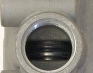
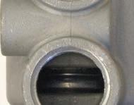
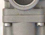
18 *THREE-WAY (3 port-2 position & 3 port-3 position) BODY ASSEMBLIES *Two-way function may be provided by plugging the exhaust port (EA or 1) of Three-way Body Assembly. Body Assemblies with 2-outlet or 2-inlet function, see page /4 NPT & 3/8 NPT **3/2 (three-port 2-position) BODY ASSEMBLY SA /4 NPT SA /8 NPT **Body Assemblies for NC and NO functions are identical. For NC function the Return Device should be mounted at the LH side ; for NO function at the RH side * * 3/3 (three-port 3-position) BODY ASSEMBLY SA /4 NPT SA /8 NPT Dimensions for 3/3 (Three-Port 3-position) Body Assemblies are the same as for 2-position Body Assemblies shown above SA /4 NPT SA /8 NPT NOTE: Product number designations and subassembly numbers that are listed are for EXPilot type valves; for INPilot type valves the third digit 0 is exchanged for
19 *THREE-WAY (3 port-2 position & 3 port-3 position) BODY ASSEMBLIES *Two-way function may be provided by plugging the exhaust port ( EA 1 ) of Three-way Body Assembly. Body Assemblies with 2-outlet or 2-inlet function, see page /2 NPT **3/2 (three-port 2-position) BODY ASSEMBLY SA /2 NPT **Body Assemblies for NC and NO functions are identical. For NC function the Return Device should be mounted at the LH side ; for NO function at the RH side. 3/3 (three-port 3-position) BODY ASSEMBLY SA /2 NPT Dimensions for 3/3 (Three-Port 3-position) Body Assemblies are the same as for 2- position Body Assemblies shown above SA /2 NPT NOTE: Product number designations and subassembly numbers that are listed are for EXPilot type valves; for INPilot type valves the third digit 0 exchanged for
20 TWO-INLET or TWO-OUTLET FUNCTION (3/2 & 3/3) BODY ASSEMBLIES 1/4 NPT & 3/8 NPT LH side RH side Ø 2 HOLES IN 2 N.J., USA & Netherlands OUT 3 OUT 3 VERSA /2 (three-port 2-position) BODY ASSEMBLY /4 NPT or 3/8 NPT 3 PORTS SA /4 NPT SA /8 NPT Ø 2 HOLES OUT 2 N.J., USA & Netherlands IN 3 IN SA /4 NPT /4 NPT or 3/8 NPT 3 PORTS SA /8 NPT /4 NPT = /8 NPT = Dimensions for 3/3 (Two-Inlet & Two-Outlet) Body Assemblies are the same as for 2-position Body Assemblies shown above. 3/3 (three-port 3-position) BODY ASSEMBLY Body Assemblies with 3-position function: change fourth digit 2 in sub-assembly number into 3 for all ports blocked in center position. NOTE: Product number designations and subassembly numbers that are listed are for ExPilot type valves; for INPilot type valves the third digit 0 is exchanged for
21 TWO-INLET or TWO-OUTLET FUNCTION (3/2 & 3/3) BODY ASSEMBLIES 1/2 NPT 3/2 (three-port 2-position) BODY ASSEMBLY SA /2 NPT (A/2 = INLET; IN/3 + EA/1 = OUTLET) SA /2 NPT (IN/3 + EA/1 = INLET: A/2 = OUTLET) 3/3 (three-port 3-position) BODY ASSEMBLY Dimensions for 3/3 (Two-Inlet & Two-Outlet) Body Assemblies are the same as for 2-position Body Assemblies shown above. Body Assemblies with 3-position function: change fourth digit 2 in sub-assembly number into 3 for all ports blocked in center position. NOTE: Product number designations and subassembly numbers that are listed are for ExPilot type valves; for INPilot type valves the third digit 0 is exchanged for
22 FOUR-WAY (5 port-2 position & 5 port-3 position) BODY ASSEMBLIES 1/4 NPT & 3/8 NPT Ø 3HOLES A2 B4 N.J., USA & Netherlands EB IN EA 1 VERSA 1/4 NPT 5 PORTS /2 (fi ve-port 2-position) BODY ASSEMBLY SA /4 NPT SA /8 NPT /3 (fi ve-port 3-position) BODY ASSEMBLY SA /4 NPT SA /8 NPT Dimensions for 5/3 (Five-Port 3-position) Body Assemblies are the same as for 2-position Body Assemblies shown above SA /4 NPT SA /8 NPT NOTE: Product number designations and subassembly numbers that are listed are for EXPilot type valves; for INPilot type valves the third digit 0 is exchanged for
23 FOUR-WAY (5 port-2 position & 5 port-3 position) BODY ASSEMBLIES 1/2 NPT 5/2 (fi ve-port 2-position) BODY ASSEMBLY SA /2 NPT 5/3 (fi ve-port 3-position) BODY ASSEMBLY SA /2 NPT Dimensions for 5/3 (Five-Port 3-position) Body Assemblies are the same as for 2-position Body Assemblies shown above SA /2 NPT NOTE: Product number designations and subassembly numbers that are listed are for EXPilot type valves; for INPilot type valves the third digit 0 is exchanged for


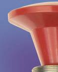
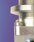
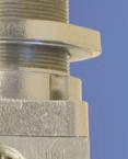
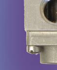
24 316 STAINLESS STEEL ACCESSORIES Manual Shut Off Valves General Description For Emergency Shut Down Systems, a Manual Bleed Valve designated MSO , and a Manual Block and Bleed Valve designated MS Both valves, constructed of 316 Stainless Steel, are used as panic valves to quickly depressurize the system to get immediate shut-down. Even from remote locations, they enable the user to shutdown various processes in case of an emergency. Manual Bleed Valve The valve MS is a 2-way valve that is closed during normal operation. By pulling the red panel knob out, the valve opens and the Emergency Shutdown system pressure is dumped to atmosphere. Although compact and light weight, an internal orifi ce of 3/8 assures quick shut-down of the system. Because the valve is designed to work as a bleed type device only, any backpressure to the exhaust port will cause the valve to shift and open the inlet gate as if the panel knob were pulled out. Manual Block and Bleed Valve The valve MSO is a 3-way valve that can be used in the Emergency Shutdown system loop. During normal operation the inlet port is open to the outlet port, and the exhaust port is closed. By pulling the panel knob out, the inlet port is blocked and the outlet port is opened to exhaust port, so that the downstream system pressure is dumped to the atmosphere. Like the manual bleed valve, any backpressure to the exhaust port of the valve will cause the valve to shift, dumping downstream pressure, as if the panel knob were pulled out. Materials (Conform to NACE Standard MR-01-75) Stainless Steel - FKM (Fluorocarbon) O ring seals - Plastic palm button Weights MS lbs. (.35 kg) MS lbs. (.45 kg) Pressures On inlet port On exhaust port Porting & Flow Valve ports 1/4 NPT MS : Cv=2.0 (Kv=29) MS : Cv=1.0 (Kv=14.5) :0 to 150 psi (10 bar) air :0 psi (0 bar) backpressure Installation The valves can be panel mounted. Panel hole is 1 (25.4 mm) ø TWO-WAY (2/2) THREE-WAY (3-2) Block & Bleed Charge & Bleed Product Number Knob Color Product Number Knob Color MS Red MS Black MS B Black MS R Red 9.1


 Screws: 316 stainless steel Weight: 0.")
 3 to 500 psi (0.2 to 35 bar) Cv=0.")


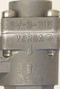
25 316 STAINLESS STEEL ACCESSORIES Shuttle Valve Shuttle valves provide the simplest way of pressurizing and exhausting a pilot chamber through the actuation of any one of two or more three-way valves. If two remote stations are required, one shuttle valve (in place of a tee) is required between the two three-way valves. For each additional remote station another shuttle valve is required. The shuttle valve prevents pressure from the actuated valve from being exhausted through the unactuated valve. In logic terms a shuttle valve is an OR function. A typical schematic is shown below: DIMENSIONS IN INCHES (mm) Materials (Conform to NACE Standard MR-01-75) Body: 316 stainless steel Shuttle: 316 stainless steel Seals: FKM (Fluorocarbon) Screws: 316 stainless steel Weight: 0.33 lbs. (0.15 kg) Porting: 1/4 NPT Pressures and Flow Pneumatic: Hydraulic: 3 to 200 psi (0.2 to 14 bar) 3 to 500 psi (0.2 to 35 bar) Cv=0.5 (Kv = 7) Installation Preferably with the centerline of the two inlet ports horizontal. As shown in the drawing above. Product Number SV Bleed Control Valves DIMENSIONS IN INCHES (mm) The VERSA Bleed Control Valve has a precision machined needle that provides an economical, effective fl ow control in pneumatic applications. They can be threaded into the exhaust port of any VERSA directional control valve to provide speed control. The fl ow area, through which the air passes to the atmosphere, can be fi nely adjusted by screwing the needle in or out. After the Bleed Control Valve has been adjusted to suit, it can be securely locked at its setting with the lock nut provided. Materials (Conform to NACE Standard MR-01-75) 316 stainless steel Product Number Pressures 0 to 200 psi (0 to 14 bar) air BC BC /4 NPT 3/8 NPT BC /2 NPT BC /4 NPT valve exhaust port 10.1
 A Quick Exhaust Valve is a 3/2 (three-way) valve with extra large exhaust orifi ce, to be fi tted directly at a cylinder")

 Body: 316 stainless steel Seals: FKM (Fluorocarbon) O ring seals and CR")
 QE-6-316 2.44 lbs (1.")

 Installation Dust Excluders are preferably mounted in a vertical position with the wide outlet opening down.")
 Temperature: QE-3-316 & QE-5-316:-20 F to 200 F (-29 C to 93 C) QE-6-316: -30 F to 350 F (-34 C to 177 C)")
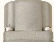
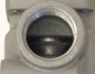
26 316 STAINLESS STEEL ACCESSORIES Quick Exhaust Valves (See Bulletin ACC for Electric Quick Exhaust Valves) DIMENSIONS IN INCHES (mm) A Quick Exhaust Valve is a 3/2 (three-way) valve with extra large exhaust orifi ce, to be fi tted directly at a cylinder port connection. When pressure decreases at the inlet of the Quick Exhaust Valve, the outlet is automatically opened to the exhaust and the cylinder is quickly depressurized. Materials (Conform to NACE Standard MR-01-75) Body: 316 stainless steel Seals: FKM (Fluorocarbon) O ring seals and CR (Neoprene) coated Nylon fl apper. Other parts: 316 Stainless Steel Weights QE lbs (0.37 Kg) QE lbs (0.98 Kg) QE lbs (1.11 Kg) Dust Excluders Dust Excluders may be threaded into the exhaust ports in order to keep out dirt or dust in the atmosphere or surrounding the valve, that might enter through an otherwise open port. Materials (Conform to NACE Standard MR-01-75) Body: 316 Stainless Stell Seal: CR Chloroprene (Neoprene) Pressures 0 to 200 psi (0 to 14 bar) Installation Dust Excluders are preferably mounted in a vertical position with the wide outlet opening down. Valve exhaust port QE Consult Factory Pressures psi (0.34 to 10 bar) Temperature: QE & QE-5-316:-20 F to 200 F (-29 C to 93 C) QE-6-316: -30 F to 350 F (-34 C to 177 C) Porting Type Inlet/Outlet Exhaust QE /4 NPT 3/8 NPT QE /2 NPT 3/4 NPT QE /4 NPT 1 NPT Flow Type IN to CYL CYL to EX QE Cv=3.0(Kv=43.5) Cv=3.3 (Kv=48) QE Cv=3/8 (Kv=55) Cv=8.8 (Kv=128) QE Cv=4.6 (Kv=66) Cv=13.6 (Kv=195) Product Number QE QE QE /4 NPT 1/2 NPT 3/4 NPT Product Number DE DE /4 NPT 3/8 NPT DIMENSIONS IN INCHES (mm) DE DE /2 NPT 3/4 NPT 10.2
 General Description Some applications require visual indication, when a system is pressurized or when a system has lost pressure.")

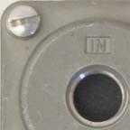
27 316 STAINLESS STEEL ACCESSORIES Status Indicator Panel Hole Opening Required : 1 Ø (25.4) 1/8-27 NPT Pressure Supply Port 1.5 (38) 2.48 (63) General Description Some applications require visual indication, when a system is pressurized or when a system has lost pressure. The Versa Status Indicator provides such a display within a stainless steel shell that can be mounted as an integral part of a panel. Viewing the panel provides the operator with an instantaneous evaluation of the pressure condition in the system or systems being monitored. Functional Description Versa s Status Indicator provides visual indication of pressure in a system. The standard product displays a green field when a minimum of 8 psi (0.55 bar) to a maximum of 200 psi (14 bar) is present. Complete loss of pressure causes the indicator to display a red field, marked with the recognition character R. Other field colors are available. See TYPES below. Materials: Body and internal wetted metal parts 316 Stainless Steel+ Working seals FKM (Fluorocarbon) Lens-polycarbonate (seal to prevent moisture intrusion), resistant to ultraviolet rays Porting: 1/8 NPT pressure supply port Pressures Operating pressure range: 0 to 200 psi (14 bar) air* Mounting Panel hole opening 1 (25.4mm) ø Can be mounted in any orientation with maximum panel thickness 0.50 (12.7mm) with one panel nut; maximum panel thickness 0.21 (5.3mm) with two panel nuts. (suffix -43E). Type/Weights Product Number SI SI GR SI YG SI GY Depressurized 0 psi (0 bar) Red (R) Green (G) Yellow (Y) Green (G) Operating Pressure Range Pressurized 8 psi (0.55 bar) to 200 psi (14 bar) Weights Green Red Green Yellow } 0.50 lbs. (0.23 kg) *For hydraulic service consult factory. Conforms to NACE standard MR
28 IF YOU HAVEN T FOUND THE VALVE YOU NEED, YOU HAVEN T ASKED US. Versa Valves designed, built, and tested to meet your air requirements. SERIES B VALVES: 1/8 NPT, 3/16 (4.7mm) Orifi ce. Two- & Three-Way. Brass & SS Construction. Manual, Pilot & Cam Actuation. Pneumatic Service Vacuum to 200 psi (14 bar). Bulletin B. SERIES B-316, B-900 & B-550 AUTOMATION AND CONTROL VALVES & COMPONENTS FOR PROCESS CONTROL: Suitable for Offshore, Process Control, Material Specs Meet NACE MR Fluorocarbon Seals, 1/4 NPT, 3/16 (5mm) Orifice. Three- Way. Solenoid/Pilot, Remote Pilot, Mechanical, Manual & Many Special Actuators. Main Supply Reset Valves; First Out Indicating Valves. Pneumatic Service Vacuum to 200 psi (14 bar). Bulletin B316 SERIES C VALVES: (M5), 1/8 NPT OR G1/8, 1/4 NPT OR G1/4, 0.6 to 7mm Orifice. Three- & Four-Way, Multi-purpose. Individual Mount, Stacking, or Manifold Mounted. Aluminum, SS & Nylon Construction. Solenoid/ Pilot, Pilot, Manual & Mechanical Actuation. Pneumatic Service Vacuum to 115 psi (8 bar). Bulletin C. SERIES E VALVES: 1/8 NPT & 1/4 NPT. 1/32 (0.8mm) thru 1/4 (6.4mm) Orifice. Two- & Three-Way, Directional, Multi-Purpose. Sideported, and Manifold Mounted. SS or Aluminum Construction. Direct Solenoid Actuation, including LOW WATT. Pneumatic & Hydraulic Service Vacuum to 500psi (35 bar). Bulletin E. SERIES K VALVES: Compact Air Management System. ¼ NPT or G1/4, 4.7mm & 6.5mm Orifi ce. Two-, Three-, Four- & Five-Way, Selector, Diverter. Manifold Mounted, Integrated Circuitry, Aluminum Construction. Fluorocarbon Seals. Solenoid/Pilot, Remote Pilot, Cam & Manual Actuation. Pneumatic Service Vacuum to 175 psi (12 bar). Bulletin K. SERIES H VALVES: High pressure hydraulic valves: High pressure valves for the Oil & Gas Industry; to 10,000 psi operating pressure, 316 stainless steel construction, leakproof, balanced dynamic ceramic sealing, O ring static seals, modular design, manifold mounting. Bulletin H SERIES V & T VALVES: 1/8 thru 1-1/4 NPT or G, Full Ported, Two-, Three-, Four- & Five- Way, Selector, Diverter. All types of Actuation. Forged Brass Construction. Pneumatic Service Vacuum to 200 psi (14 bar), Hydraulic Service to 500 psi (35 bar). Bulletin VT. SERIES V-316 STAINLESS STEEL VALVES: Suitable for Offshore, Process Control, Material Spec Meet NACE MR Fluorocarbon Seals. 1/4, 3/8, 1/2 NPT, Full Ported. Two-, Three-, Four- & Five-Way. Selector. Diverter. All Type of Actuation. Pneumatic Service Vacuum to 200 psi (14 bar). Bulletin V316. SOLENOID VALVES FOR THE PROCESS CONTROL INDUSTRY: Complete Range of Stainless Steel, Brass or Aluminum Constructed Valves, 1/8 NPT through 1 NPT. Direct NAMUR Mount & Bodyported Styles. Latching Manual Reset, Lockout Valves, Redundant Valves. Bulletin PCg. ACCESSORIES: Shuttle Valves, Bleed Control Valves, Dust Excluders, Foot Guards, Bleed Valves, Quick Exhaust Valves, Status Indicators. Bulletin ACC. The warnings below must be read and reviewed before designing a system utilizing, installing, servicing, or removing a Versa product. Improper use, installation or servicing of a Versa product could create a hazard to personnel and property. DESIGN APPLICATION WARNINGS Versa products are intended for use where compressed air or industrial hydraulic fluids are present. For use with media other than specified or for non-industrial applications or other applications not within published specifications, consult Versa. Versa products are not inherently dangerous. They are only a component of a larger system. The system in which a Versa product is used must include adequate safeguards to prevent injury or damage in the event of system or product failure, whether this failure be of switches, regulators, cylinders, valves or any other system component. System designers must provide adequate warnings for each system in which a Versa product is utilized. These warnings, including those set forth herein, should be provided by the designer to those who will come in contact with the system. Where questions exist regarding the applicability of a Versa product to a given use, inquiries should be addressed directly to the manufacturer. Confirmation should be obtained directly from the manufacturer regarding any questioned application prior to proceeding. INSTALLATION, OPERATION AND SERVICE WARNINGS Do not install or service any Versa product on a system or machine without first depressurizing the system and turning off any air, fluid, or electricity to the system or machine. All applicable WARNINGS REGARDING THE DESIGN APPLICATION, INSTALLATION AND SERVICE OF VERSA PRODUCTS electrical, mechanical, and safety codes, as well as applicable governmental regulations and laws must be complied with when installing or servicing a Versa product. Versa products should only be installed or serviced by qualified, knowledgeable personnel who understand how these specific products are to be installed and operated. The individual must be familiar with the particular specifications, including specifications for temperature, pressure, lubrication, environment and filtration for the Versa product which is being installed or serviced. Specifications may be obtained upon request directly from Versa. If damages should occur to a Versa product, do not operate the system containing the Versa product. Consult Versa for technical information. LIMITED WARRANTY DISCLAIMER AND LIMITATION OF REMEDIES Products sold by Versa are warranted to be free from defective material and workmanship for a period of ten years from the date of manufacture, provided said items are used in accordance with Versa specifications. Versa s liability pursuant to that warranty is limited to the replacement of the Versa product proved to be defective provided the allegedly defective product is returned to Versa or its authorized distributor. Versa provides no other warranties, expressed or implied, except as stated above. There are no implied warranties of merchantability or fitness for a particular purpose. Versa s liability for breach of warranty as herein stated is the only and exclusive remedy and in no event shall Versa be responsible or liable for incidental or consequential damages. Versa Products Company, Inc., 22 Spring Valley Road, Paramus, New Jersey, USA / FAX: 201/ Versa BV., Prins Willem Alexanderlaan 1429, 7312 GB Apeldoorn, The Netherlands FAX:
ACCESSORIES FOR AIR VALVES & AIR SYSTEMS
 ACCESSORIES FOR AIR VALVES & AIR SYSTEMS BULLETIN ACC-2000R AIR VALVES FOR INDUSTRY SINCE 1949 ISO 9001 CERTIFIED FOOT GUARDS Page 8 QUICK EXHAUST & ELECTRIC QUICK EXHAUST VALVES Pages 6 & 7 SHUTTLE VALVES
B SERIES. Bulletin B-2017
 Bulletin B-207 B SERIES Versa Product Company, Inc., 22 Spring Valley Rd., Paramus, NJ 0762 USA Phone: (20) 4-2400 Fax: (20) 4-29 Versa BV, Prins Willem Alexanderlaan 427, 72 GB Apeldoorn, The Netherlands
Bulletin H-Tech 03 High Pressure Valves Series H
 Bulletin H-Tech 03 High Pressure Valves Series H VALVES The H Series Leak-Proof, High-Pressure Valves Versa Products Company has been supplying high quality pneumatic and hydraulic directional control
Modular Air Package. Bulletin VMAP-15.
 Bulletin VMP-15 Modular ir Package Versa Product Company, Inc., 22 Spring Valley Rd., Paramus, NJ 07652 US Phone: (201)-843-2400 Fax: (201)-843-2931 Versa BV, Prins Willem lexanderlaan 1429, 7312 GB peldoorn,
SERIES C TYPE VALVES C3 VALVES Port Sizes: Four-Way 5/ UNF or M5 Pneumatic-vacuum to 115 psi (8 bar) (individual valves) Gang mounting (2 or mo
 (individual valves) Gang mounting (2 or mo") CONDENSED CATALOG CC-2004 SERIES C TYPE VALVES C3 VALVES Port Sizes: Four-Way 5/2 10-32 UNF or M5 Pneumatic-vacuum to 115 psi (8 bar) (individual valves) Gang mounting (2 or more valves) Supply & Exhaust
CONDENSED CATALOG CC-2004 SERIES C TYPE VALVES C3 VALVES Port Sizes: Four-Way 5/2 10-32 UNF or M5 Pneumatic-vacuum to 115 psi (8 bar) (individual valves) Gang mounting (2 or more valves) Supply & Exhaust
AUTOMATION CONTROL VALVES COMPONENTS FOR PROCESS CONTROL
 AUTOMATION CONTROL VALVES COMPONENTS FOR PROCESS CONTROL BULLETIN B316-2004 ISO 9001 CERTIFIED www.versa-valves.com e-mail: sales@versa-valves.com Versa Products Company, Inc., 22 Spring Valley Road, Paramus,
DIECT MOUNT CTUTO VLVES LUMINUM CONSTUCTION SEIES C5 NMU General Description The Versa C5 NMU mount control valve is a high flow, 5-port, solenoid/pil
 NMU DIECT MOUNT PNEUMTIC CTUTO VLVES I VLVES FO INDUSTY SINCE 1949 BULLETIN NMce-2004 SOLENOID CTUTION 1/4 NPT or G1/4 DIECT MOUNT TO MNY DIFFEENT CTUTOS 10 YE WNTY C5 Series: E5 Series: 3-way or 4-way,
CONDENSED CATALOG CC
 CONDENSED CATALOG CC-2004 THE COMMITMENT CONTINUES Fluid Power is our business. It is our only business, so we have to be good at it. Since its beginning in 1949, Versa has maintained its commitment to
Versa exercises diligence to assure that information contained in this catalog is correct, but does not accept responsibility for any errors or omissi
 SERIES B VALVES AIR VALVES FOR INDUSTRY SINCE 1949 ISO 9001 Two-Way Types for bleeding pilots of larger valves, for bleeding cylinders or small pressure systems, operating air tools or motors, opening
ACCESSORIES FOR AIR VALVES & AIR SYSTEMS
 BULLETIN CC-2011 CCESSORIES FOR IR VLVES & IR SYSTEMS SI QE SV BC FCV RV DE DE DE ISO 9001 BB BV CERTIFIED IR VLVES FOR INDUSTRY SINCE 1949 Versa Products Company, Inc., 22 Spring Valley Road, Paramus,
ACCESSORIES FOR AIR VALVES & AIR SYSTEMS
 ULLETIN CC-2017 CCESSORIES FOR IR VLVES & IR SYSTEMS SI QE SV C FCV RV DE DE DE ISO 9001 V CERTIFIED Versa Products Company, Inc., 22 Spring Valley Road, Paramus, New Jersey, US 07652 TEL: 201-843-2400
Versa exercises diligence to assure that information contained in this catalog is correct, but does not accept responsibility for any errors or omissi
 SOLENOID VLVES FOR THE PROCESS CONTROL INDUSTRY IR VLVES FOR INDUSTRY SINCE 1949 www.versa-valves.com BULLETIN PCg-2001 ISO 9001 CERTIFIED TEL:201/843-2400 FX: 201/843-2931 Versa Products Company, Inc.,
AIR PREPARATION. Filters & Regulators 316 Stainless Steel. Bulletin AP
 Bulletin AP-316 218 AIR PREPARATION Filters & Regulators Versa Product ompany, Inc., 22 Spring Valley Rd., Paramus, NJ 7652 USA Phone: (21)-843-24 Fax: (21)-843-2931 Versa BV, Prins Willem Alexanderlaan
The H Series Leak-Proof, High-Pressure Valves Versa Products Company has been supplying high quality pneumatic and hydraulic directional control valve
 High Pressure Valves Series H Bulletin H-Tech 0 VALVES The H Series Leak-Proof, High-Pressure Valves Versa Products Company has been supplying high quality pneumatic and hydraulic directional control valves
CONDENSED CATALOG CC
 CONDENSED CATALOG CC-2016 e-mail: sales@versa-valves.com THE COMMITMENT CONTINUES Fluid Power is our business. It is our only business, so we have to be good at it. Since its beginning in 1949, Versa has
SOLENOID VALVES FOR PROCESS CONTROL INDUSTRIES AIR VALVES FOR INDUSTRY SINCE 1949
 SOLENOID VLVES FOR PROCESS CONTROL INDUSTRIES ULLETIN PCg-200 IR VLVES FOR INDUSTRY SINCE 949 ISO 900 CERTIFIED www.versa-valves.com e-mail: sales@versa-valves.com Versa Products Company, Inc., 22 Spring
ICO2S - 2/2, 3/2 or 5/2 Exia poppet valves Electromagnetically actuated, solenoid pilot operated
 ICOS - /, / or 5/ Exia poppet valves > > Port size: /... / (ISO G/NPT) /... (Flanged) > > Zone 0, Exia solenoid pilot operated valve > > Safety integrity level and > > Reliable and long life, ideal for
Control & Power, Inc
 Way/ 2 and 3 Position Four ported valves are generally used to operate double-acting cylinders or actuators. They have four or five pipe connections, commonly called ports: One pressure inlet. Two cylinder
FITTINGS CHEST FITTINGS CHEST. Get organized with the Pneuforce Fittings Chest!
 FITTINGS CHEST FITTINGS CHEST Get organized with the Pneuforce Fittings Chest! Over 40 Different Compartments Easy Carry Handle Holds and Includes 420 Fittings All threaded Models Have the Unique Pneuforce
Easytork Solenoid Valve IOM
 Easytork Solenoid Valve IOM General This installation document is to be read in conjunction with the Easytork Vane Actuator IOM. Description The Easytork Solenoid Valve ( ESV ) series is intended for the
Engineering Information. Solenoid Valves Principles of Operation. Solenoid Valves. Direct Acting Valves (Figures 1A, 1B)
") 4 Engineering Information Principles of Operation A solenoid valve is a combination of two basic functional units: A solenoid (electromagnet) with its core A valve body containing one or more orifices
4 Engineering Information Principles of Operation A solenoid valve is a combination of two basic functional units: A solenoid (electromagnet) with its core A valve body containing one or more orifices
Type 2511/12. Type Type 2030 Cable plug. ASI cable plug. Dosing control. General technical data Orifice Type 6518
 3/2-, 5/2- and 5/3-way Solenoid Valves for process pneumatics Type 658 standard standard High flow-rate capacity Reduced power consumption Single or manifold mounting Standard-, EEx m and EEx i versions
3/2-, 5/2- and 5/3-way Solenoid Valves for process pneumatics
 /-, 5/- 5/-way Solenoid Valves for process pneumatics Type 658 stard High flow-rate capacity Reduced power consumption Single or manifold mounting stard Type 658/659 can be combined with... Stard-, EEx
% ^ ) 4/2 SERIES. Direct Mount. Direct Acting Direct Mount Pilot Valves. Brass or Stainless Steel Bodies 1/4" NPT. Features. Construction.
 4/2 SERIES. Direct Mount. Direct Acting Direct Mount Pilot Valves. Brass or Stainless Steel Bodies 1/4 NPT. Features. Construction.") Direct Acting Direct Mount Pilot Valves Brass or Stainless Steel Bodies /" NPT / 83 Direct Mount Features NAMUR direct mount version of the rugged, dependable 83 Series valves Direct acting, high flow
Direct Acting Direct Mount Pilot Valves Brass or Stainless Steel Bodies /" NPT / 83 Direct Mount Features NAMUR direct mount version of the rugged, dependable 83 Series valves Direct acting, high flow
3/2-, 5/2- and 5/3-way Solenoid Valves for process pneumatics
 /2-, 5/2-5/-way Solenoid Valves for process pneumatics Type 658 stard High flow-rate capacity Reduced power consumption Single or manifold mounting stard Type 658/659 can be combined with... Stard-, EEx
Mini 1. Compact High Flow 3-Way and 4-Way Pneumatic Directional Control Valves
 Catalog LX-530 Mini 1 Compact High Flow and Pneumatic Directional Control Valves FEATURES: 3-port or 5-port bodies Manual, Air Pilot, Solenoid or Mechanical Operators Two-position, Single or Dual Actuation
3 Way/2 Position Valves
 Way/ Position Valves Three way valves have three pipe connections and two orifices. When one orifice is open, the other is closed, and vice versa. They are commonly used to alternately apply pressure to
V82 series - Redundant valve manifold systems - Compact 1oo2 Safety, 2oo2 Availability and 2oo3 Safety and Availability
 V8 series - Redundant valve manifold systems - Compact oo Safety, oo Availability and oo Safety and Availability > > Compact design - Herion valves > > Exhaust guards as standard > > SIL certified components
Poppet Valves Series. Keeping the World Flowing
 Poppet Valves 750 Series Keeping the World Flowing Contents Section Page Introduction 750 Series Poppet Valve Pilot operated 4 /4 to / Pilot operated 5 /4 to Pilot operated 6 Pilot operated 7 /4 to / Pilot
3/2-way Small Solenoid Valve, G 1/8 - G 1/4 and sub-base
 3/2-way Small Solenoid Valve, G 1/8 - G 1/4 and sub-base Sub-base Direct-acting, normally closed and normally open Brass and stainless steel body Electrical cable plug Form A With or without manual override
% # ) Air and Inert Gas Intrinsically Safe Valves 2/2 3/2 4/2 5/2 5/3 SERIES. Brass, Aluminum, or Stainless Steel Bodies 1/4" to 1" NPT
 Air and Inert Gas Intrinsically Safe Valves 2/2 3/2 4/2 5/2 5/3 SERIES. Brass, Aluminum, or Stainless Steel Bodies 1/4 to 1 NPT") 4 Air and Inert Gas Intrinsically Safe Valves Brass, Aluminum, or Stainless Steel Bodies /4" to " NPT / 3/ 4/ 5/ 5/3 Features Intrinsically safe solenoid enclosures to provide corrosion resistance in harsh
4 Air and Inert Gas Intrinsically Safe Valves Brass, Aluminum, or Stainless Steel Bodies /4" to " NPT / 3/ 4/ 5/ 5/3 Features Intrinsically safe solenoid enclosures to provide corrosion resistance in harsh
2oo2 with bypass valve exhaust guards and indicators. 2oo2 I4. N/en
 V8 series Redundant valve manifold systems - Modular with bypass oo Safety, oo Availability and oo Safety and Availability Modular design - Maxseal valves ypass function enables valve removal online Stainless
SKINNER Intrinsically Safe Series Four-Way
 SKINNER Four-Way Two-Position Valves SPECIFICATIONS Mechanical Characteristics Standard Materials of Body Aluminum Seals FKM, NBR. Other diaphragm materials available upon request. Compatible Fluids Air
3/8 & 1/2 NPT. 4-Way - 5 Ported - 2 Position - Type 2 Use on all 4 Way - 2 Position applications
 8 SERIES: /8 Ported Air Valves, A & B SERIES: / Ported Air Valves /8 & /, A, B & 8 Series, & Way; & Position Operation to 50 psi Note! Spring return & spring centered models NOT suitable for dry air service.
Port Flow Rate/ Function Series Actuators Page Number Size Factor
 Section dex Port Flow Rate/ Function Series Actuators Page Number Size Factor 0- Cv = 0.05 Way Modular Solenoid. -. & to Way Manifold /8 NPT Cv = 0. Way, Position Modular /8 NPT Cv = 0.05 Way Hex Solenoid.5.6
Miniature I/P, E/P Transducer
 Miniature I/P, E/P Transducer Accurate and economical electronic pressure control The Type 550X is an electronic pressure regulator that converts a variable signal (current or voltage) to a proportional
3/2, 5/2, 5/2 bistable and 5/3 way pneumatic solenoid valve
 3/2, 5/2, 5/2 bistable and 5/3 way pneumatic solenoid valve Type 6518 Type 6519 Type 6518/6519 can be combined with... Single or block mounting Suitable for outdoor and chemical atmospheres Suitable for
C-316 SERIES. Bulletin C
 ulletin -316 2014-316 SERIES Versa Product ompany, Inc., 22 Valley Rd., Paramus, NJ 07652 US Phone: (201)-843-2400 Fax: (201)-843-2931 Versa V, Prins Willem lexanderlaan 1429, 7312 G peldoorn, The Netherlands
% # ) Intrinsically Safe & Non-Incendive Field Wiring Valves Aluminum, Brass, or Stainless Steel Bodies 1/4" to 1" NPT
 Intrinsically Safe & Non-Incendive Field Wiring Valves Aluminum, Brass, or Stainless Steel Bodies 1/4 to 1 NPT") Intrinsically Safe & Non-Incendive Field Wiring Valves Aluminum, Brass, or Stainless Steel Bodies /" to " NT / 3/ / 5/ 5/3 Features Available in different coil terminations H Class coil construction Designed
Intrinsically Safe & Non-Incendive Field Wiring Valves Aluminum, Brass, or Stainless Steel Bodies /" to " NT / 3/ / 5/ 5/3 Features Available in different coil terminations H Class coil construction Designed
97100 Inline 3/2, 5/2 & 5/3 spool valves electromagnetic actuated, indirectly controlled G 1/4, 1/4 NPT
 97 Inline /, 5/ & 5/ spool valves electromagnetic actuated, indirectly controlled G /, / NPT For single and double operated actuators Crossover-free switching, switch-over function guaranteed even with
SERIES V & T VALVES AIR VALVES FOR INDUSTRY SINCE 1949
 SERIES V & T VLVES BULLETIN VT-00 IR VLVES FOR INDUSTRY SINCE 99 ISO 900 CERTIFIED www.versa-valves.com e-mail: sales@versa-valves.com Versa Products Company, Inc., Spring Valley Road, Paramus, New Jersey,
Direct-acting 3/2 way plunger valve
 Direct-acting 3/2 way plunger valve Direct-acting, compact valve with diameter of up to DN 2.5 Vibration-proof, bolted coil system Banjo threaded connection for direct mounting on pneumatic valves Type
TECHNICAL BULLETIN. Logix 510si Series Digital Positioner. Experience In Motion FCD LGENTB /09
 Logix 510si Series Digital Positioner TECHNICAL BULLETIN FCD LGENTB0510-01 09/09 Experience In Motion Introduction The Logix 510si series are single acting, user-friendly digital positioners. As all positioners
3/8 & 1/2 NPT. with 3/8 and 1/2 NPT ports for 4 Way - 2 & 3 Position see Pg locate counterbores in body to control static squeeze on seals.
 8 SERIES /8 Ported Air Valves 1/ Ported Air Valves /8 & 1/ 1, 1A, 1B & 8 Series Note! Spring return & spring centered models NOT suitable for dry air service. Features & Way - Position. Way - &. operator
Maximum Line Resistance vs. Length of Wire Max. Loop Resistance. Max. Wire Run 18AWG 7x26 Stranded (ft)
") . W Solenoid Valves Aluminum, Brass, or Stainless Steel Bodies /" to " NPT / 3/ / 5/ 5/3 Features Molded one-piece solenoid with highly efficient solenoid cartridge and special low wattage coil Increased
. W Solenoid Valves Aluminum, Brass, or Stainless Steel Bodies /" to " NPT / 3/ / 5/ 5/3 Features Molded one-piece solenoid with highly efficient solenoid cartridge and special low wattage coil Increased
V200 Positioner. V200 P Pneumatic Positioner. V200 E Electropneumatic Positioner. Housing Material: Cast aluminium with polyester coating
 V200 Positioner Housing Material: Cast aluminium with polyester coating Indicator Options: Flat pointed indicator or raised indicator (red/green or yellow/black) One housing for pneumatic or electropneumatic
Operating pressure (bar) kv factor (m 3 /h) *3)
 kv factor (m 3 /h) *3)") / poppet valves (stainless steel) electromagnetic actuated, directly controlled G /8, G /4 or /4 NPT Working from 0 bar up Assembled free of oil and grease Suited for fine vacuum down to,33 0 - mbar For
/ poppet valves (stainless steel) electromagnetic actuated, directly controlled G /8, G /4 or /4 NPT Working from 0 bar up Assembled free of oil and grease Suited for fine vacuum down to,33 0 - mbar For
Series 1, 2 & 6 Options selector. Port 4 = 1/8" NPT 5 = 1/4" NPT (Series 6* only) 7 = #10-32 UNF 8 = 1/4-28 UNF
 7 = #10-32 UNF 8 = 1/4-28 UNF") KIP Isolation Valves Ideal for control of corrosive and aggressive media Elastomer diaphragm provides protection from aggressive, corrosive, and gritty media Isolation valves can be equipped with a low
KIP Isolation Valves Ideal for control of corrosive and aggressive media Elastomer diaphragm provides protection from aggressive, corrosive, and gritty media Isolation valves can be equipped with a low
Control Valve Specifications
 Control Valve Specifications Available in two-way, three-way and four-way configuration and with port sizes from 10-32UNF through to 1/2"NPT. The N2V & N3V1 offering is a direct acting solenoid poppet
Stainless Steel Pilot Piston Solenoid Valve 2MS Series for High Temperature & High Pressure
 Stainless Steel Pilot Piston Solenoid Valve 2MS Series for High Temperature & High Pressure S T C TM To Order, Please Specify: 1) Model No., 2) Voltage 2 Way, NC Pilot Piston Stainless Steel Part No. Voltage
Function. Orifice (mm) NBR (Perbunan) 0 EPDM 1 FKM (Viton) 2 FFKM (Kalrez) / O-ring FKM 4
 NBR (Perbunan) 0 EPDM 1 FKM (Viton) 2 FFKM (Kalrez) / O-ring FKM 4") Working from 0 bar up Short switching times Suited for fine vacuum down to 1,33 10-3 mbar Assembled oil and grease-free For a.c. solenoid systems with integrated rectifier (40 to 60 Hz) These solenoid
Working from 0 bar up Short switching times Suited for fine vacuum down to 1,33 10-3 mbar Assembled oil and grease-free For a.c. solenoid systems with integrated rectifier (40 to 60 Hz) These solenoid
Type Installation, Operation and Maintenance Instructions. Ordering Information. Contents CA20 -
 Type 2000 Pneumatic and Electropneumatic Valve Positioner Installation, Operation and Maintenance Instructions Ordering Information Use this coding system to order Model CA20 - Type of Positioner 00 P/P
97105 Inline. Ordering information. Technical data. Accessories See page 5
 75 Inline /-, 5/- and 5/ directional valves Actuation: electromagnetic Indirectly controlled soft seal spool valves G /, / NPT, G /, / NPT For single and double operated actuators Crossover-free switching,
Field IT Actuators & Positioners Electro-Pneumatic Converters I/P Signal Converters Standard Model with Booster Stage
 Data Sheet Field IT Actuators & Positioners Electro-Pneumatic Converters I/P Signal Converters Standard Model with Booster Stage Reliable through well-proven concept - More than 1,000,000 units in use
Deep Well Pump Control Valve
 MODEL 61-02 661-02 Deep Well Pump Control Valve Prevent Surges in Pipelines Simple Hydraulic Operation Adjustable Opening & Closing Speeds Solenoid Control Can Be Operated Manually Proven Reliable Design
PROCESS & AUTOMATED VALVES
 Process & utomated Valves HYDC s line of Process and utomated Valves complements our isolation valve knowhow and ability to supply high quality solutions to your valve requirements. 3-1 HV Series Inline
4V130P-430P SERIES AIR PILOT VALVE
 4V130P-430P SERIES AIR PILOT VALVE Valve Model 4V130P-1/8 4V230P-1/4 4V330P-3/8 4V430P-1/2 Port & Mounting Action & Motion Operating Pressure Body Ported Double Solenoid, Spool Design, 3 Position, Pressure
97100 NAMUR. Technical data
 9700 NAMUR /2-, /2- and / Directional control valves Actuation: electromagnetic Indirectly controlled soft seal spool valves Port size: G /4, /4 NPT NAMUR Interface For single and double operated actuators
Miniature I/P, E/P Transducer for Electronic Air Pressure Control
 Type 900X Miniature I/P, E/P Transducer for Electronic Air Pressure Control Self-correcting to maintain precise control Available with zero-based ranges The Type-900X I/P, E/P transducer converts an electrical
Material pressure (bar) (Cv (US) kv x 1,2 Seat
 (Cv (US) kv x 1,2 Seat") 00 / way poppet valves electromagnetic actuated, directly controlled G /, / NPT or flanged with NAMUR Interface TÜV-approval based on IEC 6 08, DIN V 9 Valves for safety systems up to SIL Solenoid valve
00 / way poppet valves electromagnetic actuated, directly controlled G /, / NPT or flanged with NAMUR Interface TÜV-approval based on IEC 6 08, DIN V 9 Valves for safety systems up to SIL Solenoid valve
COILS, CONNECTORS, SOLENOID VALVES
 COILS, CONNECTORS, SOLENOID VALVES 117 10 mm solenoids Solenoid valve 10 mm 00.441.0 Tension 24V DC ±10% Temperature range -5 C...+60 C (23 F... 140 F) Power 0.5... 1 W Operating pressure 0... 7 bar (0...
2/2 or 3/2-way Solenoid Valve, with pivoted armature and isolating diaphragm
 / or 3/-way Solenoid Valve, with pivoted armature and isolating diaphragm Type 0330 can be combined with Lockable manual override as standard For liquid, gaseous and aggressive media Long service life,
Offshore and Onshore Applications Lucifer TM 2/2 and 3/2 ways 316L Stainless Steel solenoid valves
 aerospace climate control electromechanical filtration fluid & gas handling hydraulics pneumatics process control sealing & shielding courtesy of Statoil Offshore and Onshore Applications Lucifer TM 2/2
Series VP4 50/4 70. Large Size 5 Port Solenoid Valve Rubber Seal SJ SY SY SV SYJ SZ VF VP4 S0700 VQ VQ4 VQ5 VQC VQC4 VQZ SQ VFS VFR VQ7 VP4
 Type of actuation 4 Piping 0 Side ported Bottom ported 4 Without sub-plate Large Size 5 Port Solenoid Valve Rubber Seal Series 50/4 70 Series VP 5 port solenoid valve 5 7 position single position double
2-Way/2 Position Valves
 4 2-Way/2 Position Valves Two-way solenoid valves have one inlet and one outlet, and are used to permit and shut off fluid flow. Two Types of Operations Apply Normally Closed (NC) Fluid is shut off when
Miniature I/P, E/P Transducer for Electronic Air Pressure Control
 Miniature I/P, E/P Transducer for Electronic Air Pressure Control Self-correcting to maintain precise control The Type-900X I/P, E/P transducer converts an electrical signal (current or voltage) to a proportional
24010, 3/2 Direct solenoid actuated poppet valve
 00, / > / (G or NPT) Inline & NAMUR > Main application: Single acting actuators in intrinsically safe circuits > Approval according to IEC 68, multichannel up to SIL > Solenoid valve with low power consumption
STC Solenoid Valve List Price
 STC Solenoid Valve List Price To Order, Please Specify: 1. Model No. 2. Voltage 3. Electrical Entry Options Voltage & Electrical Connection Options B. Electrical Connection 2V025-1/8 1/8 2/2/2/1 2V025-1/4
Redundant Control System
 Redundant Control System Safety instrumented system applications up to SIL 3 Process reliability Process valve diagnostics COMPLETE FUNCTIONAL SAFETY WITH ENHANCED RELIABILITY The Redundant Control System
Flow. group *2) G1/4 1, , B G1/ , B /4 NPT , B N/en
 G1/4 1, , B G1/ , B /4 NPT , B N/en") / poppet valves electromagnetic actuated, directly controlled G /4, G / or /4 NPT Working from 0 bar up Short switching times Suited for fine vacuum down to,33 0 - mbar For a.c. solenoid systems with integrated
/ poppet valves electromagnetic actuated, directly controlled G /4, G / or /4 NPT Working from 0 bar up Short switching times Suited for fine vacuum down to,33 0 - mbar For a.c. solenoid systems with integrated
Solenoid Valves & Accessories. Cylinder Control Bases. Features. Performance Data. Materials
 Valves & Accessories PNEUMADYNE, INC. Catalog 00 Phone 76-559-077 Fax 76-559-057 Features l Controls cylinder extension and retraction l Allows rapid cylinder return l -Way Normally Closed l Quick Exhaust
ELECTRONIC CONTROLLER
 BRQB011206E THE INSIDE STORY OF THE QB3: IP65 enclosure allows it to withstand the elements and be washed down without harm Precision pressure control vacuum to 150 psi (10.34 bar ) at high flow rate saves
26230, NAMUR 3/2 & 5/2 Indirect solenoid actuated spool valves
 60, 8007 NAMUR / & / > > Port size: G/ and NAMUR interface > > Easily interchangeable solenoid system > > For single and double operated actuators > > Standard manual override with detent > > Maintenance-free
K Series 3 Way Direct Acting Balanced Poppet Solenoid Valve
 Ex d Ex m IP5 Series 3 Way Direct Acting Balanced Poppet Solenoid Valve DB2S-M2C \ Ex d IIC with Integral Stainless \ Steel Junction Box. \ Valve. \ Manual Override, Option M2. J77072S-M2 \ Ex m II NASS
Series 810: 2 Way Angle Body Valves: 1/4 to 3 NPT
 Series 810: 2 Way Angle Body Valves: 1/4 to 3 NPT FEATURES Compact design, high fl ow rates Visual position indicator standard For temperatures from 22 F to +430 F / -30 C to 221 C Working pressures up
HERION SERIES Indirect solenoid actuated soft seal
 HERION 9700 SERIES Indirect solenoid actuated soft seal spool valves with NAMUR interface /, 5/ - G/ For single and double acting actuators Crossover-free switching, switchover function guaranteed even
3V SERIES SOLENOID VALVE
 3V110-410 SERIES SOLENOID VALVE Valve Model 3V110-1/8 3V210-1/4 3V310-3/8 3V410-1/2 Port & Mounting Action & Motion Operating Pressure Body Ported Air Pilot, Spool Design, Response Time
2/2-way Solenoid Valve with servo diaphragm
 2/2-way Solenoid Valve with servo diaphragm Type 5282 can be combined with... Pivoted armature pilot drive with manual override Magnetic drive completely isolated from fluid by diaphragm Circuit function
Poppet Valves Series
 Poppet Valves 750 Series ontents Section Page Introduction 750 Series Poppet Valve Pilot operated 4 /4 to / Pilot operated 5 /4 to Pilot operated 6 Pilot operated 7 /4 to / Pilot solenoid operated 8 /4
98025 NAMUR/INLINE 3/2 way poppet valves electromagnetic actuated, indirectly controlled G 1/2, 1/2 NPT or flanged with NAMUR Interface
 9805 NMUR/INLINE / way poppet valves electromagnetic actuated, indirectly controlled G /, / NPT or flanged with NMUR Interface Main application: single operated actuators TÜV-approval based on type examination
The extendable type 5470 EExi can be used for block modules or for entire valve blocks (tag connectors on top, coil spacing 19 mm).
.") /2- and 4/2-multi-way valves ; servo-assisted; block assembly or NAMUR flange; DN 4; flow rate: 00 l/min Advantages / Benefits II 2G EEx ia IIC T6 PTB0 ATEX 275 approved Available for block assembly and
/2- and 4/2-multi-way valves ; servo-assisted; block assembly or NAMUR flange; DN 4; flow rate: 00 l/min Advantages / Benefits II 2G EEx ia IIC T6 PTB0 ATEX 275 approved Available for block assembly and
2/2-way Angle-Seat Valve for medium up to +180 C, threaded port connection, DN 15-65
 2/2-way Angle-Seat Valve for medium up to +180 C, threaded port connection, DN 15-65 Type 2000 can be combined with High flow rate Long life cycle NC and NO universal s with modular universal accessory
High Pressure Solenoid Valves
 High Pressure Solenoid Valves Available for Quick Delivery Controls the flow of Gases & Liquids up to 15,000 PSIG Natural Gas, Hydrogen & other High Pressure Gases High Pressure Cryogenics Flammable Liquids
Electrically operated valves Series MF-04 for manifold mounting, 5/2- and 5/3-way G1/8 360 Nl/min (0.366 Cv)
") Series MF-04 for manifold mounting, 5/2- and 5/3-way G1/8 360 Nl/min (0.366 Cv) Order code MF-04-510-HN-442 Series and function (plug pins on top, see pictures) 441 = 12 V DC without plug socket 442 =
Series MF-04 for manifold mounting, 5/2- and 5/3-way G1/8 360 Nl/min (0.366 Cv) Order code MF-04-510-HN-442 Series and function (plug pins on top, see pictures) 441 = 12 V DC without plug socket 442 =
2/2 or 3/2-way Solenoid Valve, with pivoted armature and isolating diaphragm
 2/2 or 3/2-way Solenoid Valve, with pivoted armature and isolating diaphragm Lockable manual override as standard For liquid, gaseous and aggressive media Long service life, even in non-lube conditions
Electrically operated valves Series BM-01, 3/2-way and 2 x 3/2-way G1/8 550 to 660 Nl/min (0.559 to Cv)
") Electrically operated valves Series BM-01, 3/2-way and 2 x 3/2-way G1/8 550 to 660 Nl/min (0.559 to 0.671 Cv) Order code BM-01-310-HNR-462 Series and function BM = Standard Manual override HNT = non-detented
Electrically operated valves Series BM-01, 3/2-way and 2 x 3/2-way G1/8 550 to 660 Nl/min (0.559 to 0.671 Cv) Order code BM-01-310-HNR-462 Series and function BM = Standard Manual override HNT = non-detented
STC E-Series Electrically Actuated Ball Valves 316 Stainless Steel, 2-Way or 3-Way
 STC E-Series Electrically Actuated Ball Valves 316 Stainless Steel, 2-Way or 3-Way Ordering Part No. = (e.g., E 1/2-3-S) Indicator / Control E 1/2 - - - 3-S Model Name Electric Actuated Valves E Port Size
Actuated Valves PRICING
 Electric & Pneumatic Actuated Valves Actuated Valves PRICING Page Suitable for Oil-Free air handling to 5 psi, not for distribution of compressed air or gas Spears Manufacturing Company Due to Material
Kuhnke Technical Data. Contact Details
 Kuhnke Technical Data The following page(s) are extracted from multi-page Kuhnke product catalogues or CDROMs and any page number shown is relevant to the original document. The PDF sheets here may have
Product Information ROSS CONTROLS
 Product Information Minimize Hose Whip Flow Diffuser AIR-FUSE 19 Series ROSS CONTROLS AIR-FUSE Flow Diffusers Minimize Hose Whip 19 Series The ROSS AIR-FUSE Flow Diffuser automatically reduces air flow
Pneumatic Power Valves Series 75/76 Manual, Mechanical, Pneumatic and Electric Valves
 Quic-Pics Catalogue Pneumatic Power Valves Series 75/76 Manual, Mechanical, Pneumatic and Electric Valves Contents: Product Line Overviews 2 Manually Operated Valves 5 Pushbuttons 6 Toggle Switch 8 Knob
Control Reliable Double Valves with Total Dynamic Monitoring & Complete Memory
 Control Reliable Double Valves Safety Exhaust (Dump) DM Series D Self Monitored - Clutch/rake Control asic Size,,, and 0 Dynamic Monitoring With Complete Memory: Memory, monitoring, and air flow control
Actuators & Positioners Electro-Pneumatic Converters I/P Signal Converters - TEIP 11 Model without Booster Stage
 Data Sheet Actuators & Positioners Electro-Pneumatic Converters I/P Signal Converters - TEIP 11 Model without Booster Stage Reliable through well-proven concept - More than 1,000,000 units in use Compact
Electrically operated valves Series M-22, 3/2-, 5/2- and 5/3-way G1/ Nl/min (3.354 Cv)
") Electrically operated valves Series M-22, 3/2-, 5/2- and 5/3-way G1/2 3300 Nl/min (3.35 Cv) Order code Series and function M-22-310-HN-12 Standard coils 1) 11 = 12 V DC,,2 W 12 = 2 V DC,,2 W 22 = 2 V AC,
Electrically operated valves Series M-22, 3/2-, 5/2- and 5/3-way G1/2 3300 Nl/min (3.35 Cv) Order code Series and function M-22-310-HN-12 Standard coils 1) 11 = 12 V DC,,2 W 12 = 2 V DC,,2 W 22 = 2 V AC,
System 6000 Electropneumatic Converter for Direct Current Signals Type 6116 i/p Converter
 System 6000 Electropneumatic Converter for Direct Current Signals Type 6116 i/p Converter Application Used to convert a direct-current input signal into a pneumatic output signal for measuring and control
深圳市永旭伟业贸易有限公司 SOLENOID VALVES pilot operated, spool type single/dual solenoid (mono/bistable function) stainless steel body, 1/4.
 stainless steel body, 1/4.") SOLENOID VALVES pilot operated, spool type single/dual solenoid (mono/bistable function) stainless steel body, / / Series FEATURES The monostable spool valves, series, have TÜV certifi ed IEC 60 Functional
SOLENOID VALVES pilot operated, spool type single/dual solenoid (mono/bistable function) stainless steel body, / / Series FEATURES The monostable spool valves, series, have TÜV certifi ed IEC 60 Functional
Electrically operated valves Series M-07, 3/2-, 5/2- and 5/3-way G1/ and 1580 Nl/min (1.321 and Cv)
") Electrically operated valves Series M-07, 3/2-, 5/2- and 5/3-way G1/4 1300 and 1580 Nl/min (1.321 and 1.606 Cv) Order code Series and function M-07-310-HN-442 Standard coil HN at port 2 + 4 HN at port
Electrically operated valves Series M-07, 3/2-, 5/2- and 5/3-way G1/4 1300 and 1580 Nl/min (1.321 and 1.606 Cv) Order code Series and function M-07-310-HN-442 Standard coil HN at port 2 + 4 HN at port
2/2-way Solenoid Valve with servo diaphragm, G 3/8 - G 2
 2/2-way Solenoid Valve with servo diaphragm, G 3/8 - G 2 Type 6281 can be combined with... User friendly - one solenoid for all orifices Waterhammer free and low noise NC or NO Manual override optional
SERIES 740 VALVES PNEUMATIC DIRECTIONAL CONTROL
 SERIES 740 VALVES PNEUMATIC DIRECTIONAL CONTROL Specifications and features 4 Way / 2 & 3 Position Solenoid & Air Pilot Operated Diaphragm-Poppet Valve TECHNICAL DATA: Port Sizes: Integrated Fittings for
PROCESS INDUSTRY PNEUMATIC SOLUTIONS
 PROCESS INDUSTRY PNEUMATIC SOLUTIONS Pneumatrol provide engineered pneumatic solutions for use within hazardous and non-hazardous area environments. For over 50 years Pneumatrol has developed the technical