The world is movement
|
|
|
- Charlene Heath
- 6 years ago
- Views:
Transcription

1 The world is movement
2 01 SCREW JACKS
3

4 THERE IS A DRIVING FORCE MORE POWERFUL THAN STEAM, ELECTRICITY AND ATOMIC ENERGY: THE WILL. ALBERT EINSTEIN Physicist Niasa actuators in the Tonopah thermo-solar plant, Nevada, USA. Solar Reserve

5
 is activated.")
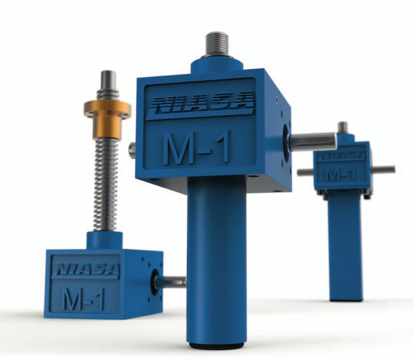
6 SCREW JACKS introduction 20 NIASA N/W/R Series screw jacks are a combination of a screw with a gearbox. There are three types of configurations that can be adapted to different requirements: N: The screw moves when the gearbox input shaft (worm shaft end) is activated. It includes a rounded screw protection tube on the back. W: The screw engages, as in configuration N but with the difference that the back protective tube is square section, which means it can be an anti-rotating screw. R: The screw does not move with the driving of the worm shaft, it only turns; it is the corresponding nut that moves along the screw. In applications that so require, there is a possibility to protect the screw with a bellow (available in different materials), to protect it in the outside environment and make the screw jacks suitable for outdoor operations or environments with a certain atmospheric aggressiveness. Screw jacks are often the most optimal technical and economical solution for applications that require lineal, precise and safe movement, for transfer and for elevation, mainly for medium-heavy loads and medium-low speeds. Their main advantages against other systems, such as pneumatic or hydraulic cylinders, are the following: Greater movement and positioning precision. Greater safety, due to their irreversibility in many configurations (ask NIASA) and/or the incorporation of different braking devices. Superior energy efficiency, as their parts offer high/very high performance, especially with the ball screws, low transmission ratios and high speeds Easier and faster assembly, since hydraulic or pneumatic groups are not required, just an electric motor on the unit itself. Greater reliability and duration, and less maintenance, due to the mechanical robustness and construction simplicity. Modular design and the possibility of operating in multiple positions. Easier to obtain synchronised advance movements of several screw jacks, including under different loads. Lower size for the same load capacity.... The screw jacks also characterised for offering an extensive range of: Axial load capacities, from 5 kn up to 500 kn. Advance speeds, depending on the screw pitch and the gearbox, two possible gears are offered depending on the size of the screw jack, from 4:1 to 56:1. Trapezoidal and ball screws, depending on the performance required, precision of movement and positioning, etc. Fastening accessories and elements, for optimal adaptation to the most varied systems that may be designed. Control and safety systems (mechanical/inductive limit switches, absolute/incremental encoders, etc.). Materials and surface coverings, depending on the environmental conditions in which the unit will be installed.... Please do not hesitate to contact NIASA if you require screw jacks (and their drive mechanisms) with specifications other than those covered in this chapter. The NIASA technical department will specifically develop the special units that best meet your requirements.
7 01 21

8 SCREW JACKS APPLICATIONS Machine TILTING system Set of two M4-N screw jacks made up of a three-phase motor drive system and joined together with a GX universal joint shaft. Tilt on the top of the gearbox with a ZKM joint adapter, SB tip supports, GKB series double clevis rod, FB protective bellow, inductive sensor and electro-magnetic brake. Manual positioning system. 22 Set of three M2-N screw jacks made up of a manual drive system with a VE series wheel and joined together with GX universal joint shafts. LCM-series mounting feet underneath the box, GKB series double clevis rod, manual brake and analogue odometer.

9 01 Photovoltaic installation M5-W screw jack with IPX protection for outdoor weather made up of a three-phase motor drive system, tilt underneath the gearbox with a ZKM joint adapter, clevis rod with GIR series ball joint on the screw, EPDM special protection bellow and inductive sensor. Platform elevation system. Set of four M5-N screw jacks made up of a three-phase motor drive system and joined together with EZ universal joint shafts and bevel gearboxes. LCM-series mounting feet underneath the box, BPS flange fastening on the screw, FB series protective bellow and PR series worm shaft protector. TILTING elevation system Set of two M5-N screw jacks made up of a dual-shaft three-phase motor drive system and joined together with GX universal joint shafts. Tilt underneath the gearbox with a ZKM joint adapter, SB tilt supports, clevis rod with GIR series ball joint on the screw, FB special protective bellow, and PR series worm shaft protector. 23
, as well as normal speed (S) and reduced speed (H) gearboxes.")


10 SCREW JACKS SIZES On all the sizes there are trapezoidal and screw drive options (see chapter 07 for further information), as well as normal speed (S) and reduced speed (H) gearboxes. Up to M1 5 kn M2 10 kn M3 25 kn M4 50 kn N The screw moves. page 28 page 30 page 32 page 34 W The screw travels. With anti-rotation on the screw. page 28 page 30 page 32 page R The nut moves. page 29 page 31 page 33 page 35 In addition to the standard range of screw jacks, NIASA can specifically develop the unit that best meets your application requirements. Contact NIASA.

11 01 M5 100 kn J1 150 kn J3 250 kn J4 350 kn J5 500 kn page 36 page 38 page 40 page 42 page 44 page 36 page 38 page 40 page 42 page page 37 page 39 page 41 page 43 page 45

12 SCREW JACKS GENERAL PRODUCT OVERVIEW N configuration W configuration 26 N/W Name Page 01 M series box Ball screw Trapezoidal screw Motor flange 05 EK coupling Motorization Wheel with VE grip PR worm gear protector GIR clevis rod GKB double clevis rod BPS flange GKS single clevis rod FB protector bellow LCM mounting feet Flange with ZKM bolts Flanges with ZKH bearings Flange with ZKV 90º bolts SB tilt supports FCM mechanical limit switch FCI inductive limit switch 306

13 Name Page R M series box Ball screw Trapezoidal screw Motor flange 05 EK coupling Motorization Wheel with VE grip PR worm gear protector KGM nut KGF nut Flange with BPR bearing EFM nut EFM safety nut FB protector bellow SF protector bellow LCM mounting feet HFM ball joint Flange with ZKM bolts Flanges with ZKH bearings Flange with ZKV 90º bolts SB tilt supports Flange with KAR bolts 275
14 M1-N/W SCREW JACKS Up to 5 kn Tr KGS TRAPEZ. BALLS The screw sizes indicated correspond to the basic configurations. Other configurations may be ordered (size, type, etc.) on request. 120 = 77 = N W Ø30 (Ø48) M12 M5x8 Prof. Greasing mechanism DIN71412 Inclined 45 MT (23) 35 (46) Key 3x3x18 DIN6885-A 1,5 5 Ø33 35* COURSE + 20 COURSE + 60* Ø10 h6 24 Ø12 Ø28 H NOTES: - The values in brackets correspond to the versions with KG screw. * Version W. = 52 = 72 M8x13 Prof. 28 Screw diameter and pitch (mm) Maximum axial strength (kn) Reduction Travel (mm/revol. input) Performance (%) Drive torque, M D F (kn), load to move in dynamic Start-up torque, M O S H S H S H S H S H Weight stroke 0 Tr 18x4 5 4:1 16: (0.44xF)+0.08 (0.14xF) xF 0.27xF KGS :1 16: (0.25xF)+0.08 (0.08xF) xF 0.13xF Approx. weight each 100mm of stroke Power required: P D (kw) = x M D. All the data in the table correspond to an input speed of 1,500 rpm. For other speeds, please see the calculation chapter (page 47).... Ensure that the dynamic load of the application does not surpass the critical values indicated, in order to avoid overheating of the unit and buckling and resonance of the screw. See calculations chapter (page 48)
15 M1-R SCREW JACKS Up to 5 kn Tr KGS BALLS TRAPEZ. 01 The screw sizes indicated correspond to the basic configurations. Other configurations may be ordered (size, type, etc.) on request. Specify orientation of the nut 15 Ø12j6 12 R Ø30 COURSE Greasing mechanism DIN71412 Inclined 45 MT (1) = = 1,5 Key 3x3x18 DIN6885-A M5x8 Prof Ø10 h6 24 Ø12 Ø28 H NOTES: - (1) See nut dimensions in the corresponding chapter. = 52 = 72 M8x13 Prof. Screw diameter and pitch (mm) Maximum axial strength (kn Reduction Travel (mm/revol. input) Performance (%) Drive torque, M D F (kn), load to move in dynamic Start-up torque, M O S H S H S H S H S H Weight stroke 0 Tr 18x4 5 4:1 16: (0.44xF)+0.08 (0.14xF) xF 0.27xF KGS :1 16: (0.25xF)+0.08 (0.08xF) xF 0.13xF Approx. weight each 100mm of stroke 29 Power required: P D (kw) = 0.157x M D. All the data in the table correspond to an input speed of 1,500 rpm. For other speeds, please see the calculation chapter (page 47).... Ensure that the dynamic load of the application does not surpass the critical values indicated, in order to avoid overheating of the unit and buckling and resonance of the screw. See calculations chapter (page 48)
 M14 M6x9 Prof.")
16 M2-N/W SCREW JACKS Up to 10 kn Tr KGS TRAPEZ. BALLS The screw sizes indicated correspond to the basic configurations. Other configurations may be ordered (size, type, etc.) on request. 140 = 90 = N W Ø39 (Ø61) M14 M6x9 Prof. Greasing mechanism DIN71412 Inclined 45 MT508 37, (21,5) 45 (48,5) 75 Key 5x5x20 DIN6885-A 1,5 5 Ø40 40* COURSE + 30 COURSE + 60* Ø14 h6 27,5 Ø15 Ø35 H NOTES: - The values in brackets correspond to the versions with KG screw. * Version W. = 63 = 85 M8x15 Prof. 30 Screw diameter and pitch (mm) Maximum axial strength (kn) Reduction Travel (mm/revol. input) Performance (%) Drive torque, M D F (kn), load to move in dynamic Start-up torque, M O S H S H S H S H S H Weight stroke 0 Tr 20x4 10 4:1 16: (0.47xF)+0.22 (0,15xF) xF 0.28xF KGS :1 16: (0.25xF)+0.22 (0.08xF) xF 0.12xF Approx. weight each 100mm of stroke Power required: P D (kw) = 0.157x M D. All the data in the table correspond to an input speed of 1,500 rpm. For other speeds, please see the calculation chapter (page 47).... Ensure that the dynamic load of the application does not surpass the critical values indicated, in order to avoid overheating of the unit and buckling and resonance of the screw. See calculations chapter (page 48)
17 M2-R SCREW JACKS Up to 10 kn Tr KGS BALLS TRAPEZ. 01 The screw sizes indicated correspond to the basic configurations. Other configurations may be ordered (size, type, etc.) on request. Ø15j6 Specify orientation of the nut R Ø39 37,5 COURSE 15 = = 1, (1) Greasing mechanism DIN71412 Inclined 45 MT Key 5x5x20 DIN6885-A M6x9 Prof Ø14 h6 27,5 Ø15 Ø35 H NOTES: - (1) See nut dimensions in the corresponding chapter. = 63 = 85 M8x15 Prof. Screw diameter and pitch (mm) Maximum axial strength (kn) Reduction Travel (mm/revol. input) Performance (%) Drive torque, M D F (kn), load to move in dynamic Start-up torque, M O S H S H S H S H S H Weight stroke 0 Tr 20x4 10 4:1 16: (0.47xF)+0.22 (0,15xF) xF 0.28xF KGS :1 16: (0.25xF)+0.22 (0.08xF) xF 0.12xF Approx. weight each 100mm of stroke 31 Power required: P D (kw) = 0.157x M D. All the data in the table correspond to an input speed of 1,500 rpm. For other speeds, please see the calculation chapter (page 47).... Ensure that the dynamic load of the application does not surpass the critical values indicated, in order to avoid overheating of the unit and buckling and resonance of the screw. See calculations chapter (page 48)
18 M3-N/W SCREW JACKS Up to 25 kn Tr KGS BALLS TRAPEZ. The screw sizes indicated correspond to the basic configurations. Other configurations may be ordered (size, type, etc.) on request. 195 = 110 = N W Ø46 M20 M8x10 Prof. Greasing mechanism DIN71412 Inclined 45 MT Key 5x5x36 DIN6885-A 5 Ø50 60* COURSE + 30 COURSE + 60* Ø16 h6 45 Ø17 Ø35 H NOTES: * Version W. 42 = 81 = 105 M10x14 Prof. 32 Screw diameter and pitch (mm) Maximum axial strength (kn) Reduction Travel (mm/revol. input) Performance (%) Drive torque, M D F (kn), load to move in dynamic Start-up torque, M O S H S H S H S H S H Weight stroke 0 Tr 30x6 25 6:1 24: (0.47xF)+0.3 (0,15xF) xF 0.31xF KGS :1 24: (0.16xF)+0.3 (0.05xF) xF 0.09xF Approx. weight each 100mm of stroke Power required: P D (kw) = 0.157x M D. All the data in the table correspond to an input speed of 1,500 rpm. For other speeds, please see the calculation chapter (page 48).... Ensure that the dynamic load of the application does not surpass the critical values indicated, in order to avoid overheating of the unit and buckling and resonance of the screw. See calculations chapter (page 48)
 Greasing mechanism DIN71412 Inclined 45 MT508 44 = 110 195 = 2 Key 5x5x36 DIN6885-A M8x10 Prof.")
19 M3-R SCREW JACKS Up to 25 kn Tr KGS BALLS TRAPEZ. 01 The screw sizes indicated correspond to the basic configurations. Other configurations may be ordered (size, type, etc.) on request. Specify orientation of the nut 25 Ø20 j6 20 R Ø46 COURSE (1) Greasing mechanism DIN71412 Inclined 45 MT = = 2 Key 5x5x36 DIN6885-A M8x10 Prof Ø16 h6 45 Ø17 Ø35 H NOTES: - (1) See nut dimensions in the corresponding chapter. = 81 = 105 M10x14 Prof. Screw diameter and pitch (mm) Maximum axial strength (kn) Reduction Travel (mm/revol. input) Performance (%) Drive torque, M D F (kn), load to move in dynamic Start-up torque, M O S H S H S H S H S H Weight stroke 0 Tr 30x6 25 6:1 24: (0.47xF)+0.3 (0,15xF) xF 0.31xF KGS :1 24: (0.16xF)+0.3 (0.05xF) xF 0.09xF Approx. weight each 100mm of stroke 33 Power required: P D (kw) = 0.157x M D. All the data in the table correspond to an input speed of 1,500 rpm. For other speeds, please see the calculation chapter (page 48).... Ensure that the dynamic load of the application does not surpass the critical values indicated, in order to avoid overheating of the unit and buckling and resonance of the screw. See calculations chapter (page 48)
20 M4-N/W SCREW JACKS Up to 50 kn Tr KGS BALLS TRAPEZ. The screw sizes indicated correspond to the basic configurations. Other configurations may be ordered (size, type, etc.) on request. 240 = 150 = N W Ø60 M30 M10x14 Prof. Greasing mechanism DIN71412 Inclined 45 MT , Key 6x6x36 DIN6885-A 2 5 Ø60 80* COURSE + 45 COURSE + 80* Ø20 h6 47,5 Ø25 Ø52 H NOTES: * Version W. = 115 = 145 M12x16 Prof. 34 Screw diameter and pitch (mm) Maximum axial strength (kn) Reduction Travel (mm/revol. input) Performance (%) Drive torque, M D F (kn), load to move in dynamic Start-up torque, M O S H S H S H S H S H Weight stroke 0 Tr 40x7 50 7:1 28: (0.51xF)+0.7 (0,15xF) xF 0.33xF KGS :1 28: (0.14xF)+0.7 (0.04xF) xF 0.07xF KGS :1 28: (0.28xF)+0.7 (0.09xF) xF 0.15xF Approx. weight each 100mm of stroke Power required: P D (kw) = 0.157x M D. All the data in the table correspond to an input speed of 1,500 rpm. For other speeds, please see the calculation chapter (page 47).... Ensure that the dynamic load of the application does not surpass the critical values indicated, in order to avoid overheating of the unit and buckling and resonance of the screw. See calculations chapter (page 48)
21 M4-R SCREW JACKS Up to 50 kn Tr KGS BALLS TRAPEZ. 01 The screw sizes indicated correspond to the basic configurations. Other configurations may be ordered (size, type, etc.) on request. Ø25 j6 Specify orientation of the nut R Ø60 58,5 COURSE = = (1) Greasing mechanism DIN71412 Inclined 45 MT Key 6x6x36 DIN6885-A M10x14 Prof Ø20 h6 47,5 Ø25 Ø52 H NOTES: - (1) See nut dimensions in the corresponding chapter. = 115 = 145 M12x16 Prof. Screw diameter and pitch (mm) Maximum axial strength (kn) Reduction Travel (mm/revol. input) Performance (%) Drive torque, M D F (kn), load to move in dynamic Start-up torque, M O S H S H S H S H S H Weight stroke 0 Tr 40x7 50 7:1 28: (0.51xF)+0.7 (0,15xF) xF 0.33xF KGS :1 28: (0.14xF)+0.7 (0.04xF) xF 0.07xF KGS :1 28: (0.28xF)+0.7 (0.09xF) xF 0.15xF Approx. weight each 100mm of stroke 35 Power required: P D (kw) = 0.157x M D. All the data in the table correspond to an input speed of 1,500 rpm. For other speeds, please see the calculation chapter (page 47).... Ensure that the dynamic load of the application does not surpass the critical values indicated, in order to avoid overheating of the unit and buckling and resonance of the screw. See calculations chapter (page 48)

22 M5-N/W SCREW JACKS Up to 100 kn Tr KGS BALLS TRAPEZ. The screw sizes indicated correspond to the basic configurations. Other configurations may be ordered (size, type, etc.) on request. 300 = 170 = N W Ø85 M36 M12x16 Prof. Greasing mechanism DIN71412 Inclined 45 MT Key 8x7x56 DIN6885-A 2,5 5 Ø82 90* COURSE + 55 COURSE + 80* Ø25 h6 67,5 Ø28 Ø52 H NOTES: * Version W. = 131 = 165 M20x30 Prof. 36 Screw diameter and pitch (mm) Maximum axial strength (kn) Reduction Travel (mm/ revol. input) Performance (%) Drive torque, M D F (kn), load to move in dynamic Start-up torque, M O S H S H S H S H S H Weight stroke 0 Tr 55x :1 36: (0.54xF)+1.68 (0.17xF) xF 0.36xF KGS :1 36: (0.22xF)+1.68 (0.07xF) xF 0.12xF Approx. weight each 100mm of stroke Power required: P D (kw) = 0.157x M D. All the data in the table correspond to an input speed of 1,500 rpm. For other speeds, please see the calculation chapter (page 47).... Ensure that the dynamic load of the application does not surpass the critical values indicated, in order to avoid overheating of the unit and buckling and resonance of the screw. See calculations chapter (page 48)
23 M5-R SCREW JACKS Up to 100 kn Tr KGS BALLS TRAPEZ. 01 The screw sizes indicated correspond to the basic configurations. Other configurations may be ordered (size, type, etc.) on request. Specify orientation of the nut 45 Ø40j6 25 R Ø85 80 COURSE = = 2, (1) Greasing mechanism DIN71412 Inclined 45 MT Key 8x7x56 DIN6885-A M12x16 Prof Ø25 h6 67,5 Ø28 Ø52 H NOTES: - (1) See nut dimensions in the corresponding chapter. = 131 = 165 M20x30 Prof. Screw diameter and pitch (mm) Maximum axial strength (kn) Reduction Travel (mm/revol. input) Performance (%) Drive torque, M D F (kn), load to move in dynamic Start-up torque, M O S H S H S H S H S H Weight stroke 0 Tr 55x :1 36: (0.54xF)+1.68 (0.17xF) xF 0.36xF KGS :1 36: (0.22xF)+1.68 (0.07xF) xF 0.12xF Approx. weight each 100mm of stroke 37 Power required: P D (kw) = 0.157x M D. All the data in the table correspond to an input speed of 1,500 rpm. For other speeds, please see the calculation chapter (page 47).... Ensure that the dynamic load of the application does not surpass the critical values indicated, in order to avoid overheating of the unit and buckling and resonance of the screw. See calculations chapter (page 48)
24 J1-N/W SCREW JACKS Up to 150 kn Tr KGS BALLS TRAPEZ. The screw sizes indicated correspond to the basic configurations. Other configurations may be ordered (size, type, etc.) on request. 325 = 200 = N W Ø90 M48x2 M12x16 Prof. Greasing mechanism DIN71412 Inclined 45 MT , Key 8x7x56 DIN6885-A 8 5 Ø90 100* COURSE + 55 COURSE + 110* Ø25 h Ø28 Ø52 H NOTES: * Version W. = 155 = 195 M24x40 Prof. 38 Screw diameter and pitch (mm) Maximum axial strength (kn) Reduction Travel (mm/revol. input) Performance (%) Drive torque, M D F (kn), load to move in dynamic Start-up torque, M O S H S H S H S H S H Weight stroke 0 Tr 60x :1 36: (0.57xF)+1.8 (0.19xF) xF 0.36xF Approx. weight each 100mm of stroke Power required: P D (kw) = 0.157x M D. All the data in the table correspond to an input speed of 1,500 rpm. For other speeds, please see the calculation chapter (page 47).... Ensure that the dynamic load of the application does not surpass the critical values indicated, in order to avoid overheating of the unit and buckling and resonance of the screw. See calculations chapter (page 48)
25 J1-R SCREW JACKS Up to 150 kn Tr KGS BALLS TRAPEZ. 01 The screw sizes indicated correspond to the basic configurations. Other configurations may be ordered (size, type, etc.) on request. Specify orientation of the nut 55 Ø45j6 25 R Ø90 COURSE Greasing mechanism DIN71412 Inclined 45 MT ,5 = = (1) Key 8x7x56 DIN6885-A M12x16 Prof Ø25 h6 65 Ø28 Ø52 H NOTES: - (1) See nut dimensions in the corresponding chapter. = 155 = 195 M24x40 Prof. Screw diameter and pitch (mm) Maximum axial strength (kn) Reduction Travel (mm/revol. input) Performance (%) Drive torque, M D F (kn), load to move in dynamic Start-up torque, M O S H S H S H S H S H Weight stroke 0 Tr 60x :1 36: (0.57xF)+1.8 (0.19xF) xF 0.36xF Approx. weight each 100mm of stroke 39 Power required: P D (kw) = 0.157x M D. All the data in the table correspond to an input speed of 1,500 rpm. For other speeds, please see the calculation chapter (page 47).... Ensure that the dynamic load of the application does not surpass the critical values indicated, in order to avoid overheating of the unit and buckling and resonance of the screw. See calculations chapter (page 48)
26 J3-N/W SCREW JACKS Up to 250 kn Tr KGS BALLS TRAPEZ. The screw sizes indicated correspond to the basic configurations. Other configurations may be ordered (size, type, etc.) on request. 355 = 225 = N W Ø120 M64x3 58 Greasing mechanism DIN71412 Inclined 45 MT Key 8x7x56 DIN6885-A 8 Ø80 M12x18Prof Ø * 82,5 COURSE COURSE + 110* Ø30 h6 67,5 Ø32 Ø58 H NOTES: * Version W. = 170 = 220 M30x45 Prof. 40 Screw diameter and pitch (mm) Maximum axial strength (kn) Reduction Travel (mm/revol. input) Performance (%) Drive torque, M D F (kn), load to move in dynamic Start-up torque, M O S H S H S H S H S H Weight stroke 0 Tr 80x :1 40: (0.65xF)+2.6 (0.19xF) xF 0.33xF KGS :1 40: (0.2xF)+2.6 (0.06xF) xF 0.08xF Approx. weight each 100mm of stroke Power required: P D (kw) = 0.157x M D. All the data in the table correspond to an input speed of 1,500 rpm. For other speeds, please see the calculation chapter (page 47).... Ensure that the dynamic load of the application does not surpass the critical values indicated, in order to avoid overheating of the unit and buckling and resonance of the screw. See calculations chapter (page 48)
27 J3-R SCREW JACKS Up to 250 kn Tr KGS BALLS TRAPEZ. 01 The screw sizes indicated correspond to the basic configurations. Other configurations may be ordered (size, type, etc.) on request. Ø60j6 Specify orientation of the nut R Ø120 COURSE (1) Greasing mechanism DIN71412 Inclined 45 MT508 = = Ø80 M12x18 Prof ,5 8 Key 8x7x56 DIN6885-A Ø30 h6 67,5 Ø32 Ø58 H NOTES: - (1) See nut dimensions in the corresponding chapter. 75 = 170 = 220 M30x45 Prof. Screw diameter and pitch (mm) Maximum axial strength (kn) Reduction Travel (mm/revol. input) Performance (%) Drive torque, M D F (kn), load to move in dynamic Start-up torque, M O S H S H S H S H S H Weight stroke 0 Tr 80x :1 40: (0.65xF)+2.6 (0.19xF) xF 0.33xF KGS :1 40: (0.2xF)+2.6 (0.06xF) xF 0.08xF Approx. weight each 100mm of stroke 41 Power required: P D (kw) = 0.157x M D. All the data in the table correspond to an input speed of 1,500 rpm. For other speeds, please see the calculation chapter (page 47).... Ensure that the dynamic load of the application does not surpass the critical values indicated, in order to avoid overheating of the unit and buckling and resonance of the screw. See calculations chapter (page 48)
28 J4-N/W SCREW JACKS Up to 350 kn Tr KGS BALLS TRAPEZ. The screw sizes indicated correspond to the basic configurations. Other configurations may be ordered (size, type, etc.) on request. Consult versions with ball screw. N W 380 = 255 = Ø145 M72x3 78 Greasing mechanism DIN71412 Inclined 45 MT Key 10x8x56 DIN6885-A 8 Ø100 M16x30 Prof Ø * COURSE + 65 COURSE + 130* Ø35 h6 65 Ø40 Ø72 H NOTES: * Version W. = 190 = 250 M36x54 Prof. 42 Screw diameter and pitch (mm) Maximum axial strength (kn) Reduction Travel (mm/ revol. input) Performance (%) Drive torque, M D F (kn), load to move in dynamic Start-up torque, M O S H S H S H S H S H Weight stroke 0 Tr 100x :1 40: (0.77xF)+3.2 (0.22xF) xF 0.4xF Approx. weight each 100mm of stroke Power required: P D (kw) = 0.157x M D. All the data in the table correspond to an input speed of 1,000 rpm. For other speeds, please see the calculation chapter (page 47).... Ensure that the dynamic load of the application does not surpass the critical values indicated, in order to avoid overheating of the unit and buckling and resonance of the screw. See calculations chapter (page 48)
29 J4-R SCREW JACKS Up to 350 kn Tr KGS BALLS TRAPEZ. 01 The screw sizes indicated correspond to the basic configurations. Other configurations may be ordered (size, type, etc.) on request. Consult versions with ball screw. Ø80j6 R Specify orientation of the nut Ø145 COURSE = = (1) Greasing mechanism DIN71412 Inclined 45 MT Ø100 M16x30 Prof. 60 Key 10x8x56 DIN6885-A Ø35 h6 65 Ø40 Ø72 H NOTES: - (1) See nut dimensions in the corresponding chapter. = 190 = 250 M36x54 Prof. Screw diameter and pitch (mm) Maximum axial strength (kn) Reduction Travel (mm/revol. input) Performance (%) Drive torque, M D F (kn), load to move in dynamic Start-up torque, M O S H S H S H S H S H Weight stroke 0 Tr 100x :1 40: (0.77xF)+3.2 (0.22xF) xF 0.4xF Approx. weight each 100mm of stroke 43 Power required: P D (kw) = 0.157x M D. All the data in the table correspond to an input speed of 1,000 rpm. For other speeds, please see the calculation chapter (page 47).... Ensure that the dynamic load of the application does not surpass the critical values indicated, in order to avoid overheating of the unit and buckling and resonance of the screw. See calculations chapter (page 48)
30 J5-N/W SCREW JACKS Up to 500 kn Tr KGS BALLS TRAPEZ. The screw sizes indicated correspond to the basic configurations. Other configurations may be ordered (size, type, etc.) on request. Consult versions with ball screw. 500 = 305 = Specify orientation Ø170 of the nut 100 M100x3 N Ø80j6 25 W Key 14x9x90 DIN6885-A (1) r Ø48 h6 230 Ø35 h6 100 = Ø50 65 Ø Ø145Greasing mechanism DIN71412 Inclined 45 MT508 8 Ø80 H7 Ø H M16x40 Prof. = 230 = M42x80 Prof. On both M36x54 sidesprof. = = 250 = Ø115 NOTES: 118 Greasing mechanism DIN71412 Inclined 45 MT508 Key 10x8x56 DIN6885-A 95 Ø M16x30 Prof. Ø * COURSE COURSE + 130* 110 COURSE * Version W. NOTES: - (1) See nut dimensions in the corresponding chapter Screw diameter and pitch (mm) Maximum axial strength (kn) Reduction Travel (mm/revol. input) Performance (%) Drive torque, M D F (kn), load to move in dynamic Start-up torque, M O S H S H S H S H S H Weight stroke 0 Tr 120x :1 56: (0.67xF)+4 (0.2xF) xF 0.4xF Approx. weight each 100mm of stroke Power required: P D (kw) = 0.157x M D. All the data in the table correspond to an input speed of 1,000 rpm. For other speeds, please see the calculation chapter (page 47).... Ensure that the dynamic load of the application does not surpass the critical values indicated, in order to avoid overheating of the unit and buckling and resonance of the screw. See calculations chapter (page 48)
31 J5-R SCREW JACKS Up to 500 kn Tr KGS BALLS TRAPEZ. 01 The screw sizes indicated correspond to the basic configurations. Other configurations may be ordered (size, type, etc.) on request. Consult versions with ball screw. Specify orientation of the nut 120 Ø95 j6 30 R Ø170 = = (1) COURSE Greasing mechanism DIN71412 Inclined 45 MT Ø115 M16x40 Prof. 60 Key 14x9x90 DIN6885-A Ø48 h6 100 Ø50 Ø80 H NOTES: - (1) See nut dimensions in the corresponding chapter. = 230 = 300 M42x80 Prof. Screw diameter and pitch (mm) Maximum axial strength (kn) Reduction Travel (mm/revol. input) Performance (%) Drive torque, M D F (kn), load to move in dynamic Start-up torque, M O S H S H S H S H S H Weight stroke 0 Tr 120x :1 56: (0.67xF)+4 (0.2xF) xF 0.4xF Approx. weight each 100mm of stroke 45 Power required: P D (kw) = 0.157x M D. All the data in the table correspond to an input speed of 1,000 rpm. For other speeds, please see the calculation chapter (page 47).... Ensure that the dynamic load of the application does not surpass the critical values indicated, in order to avoid overheating of the unit and buckling and resonance of the screw. See calculations chapter (page 48)

32 SCREW JACKS Product selection To select the correct screw jack, please follow this flow diagram. If you would like to know the expected service life of a unit for your application, please send the relevant data to the NIASA service department. 46
33 1 SCREW JACK MODEL AND SIZE DEFINITION APPLICATION 01 SCREW MOVES (Type N/W) Page 24 Page 24 NUT MOVES (Type R) 2 SCREW AND REDUCTION TYPE DEFINITION SCREW TYPE Ball (KGS) Trapezoidal (Tr) SPECIAL SIZE PRE-SELECTION Page 28 Page 28 Page 24 REDUCTION NORMAL (S) REDUCED (H) 3 SIZE VALIDATION F BUCKLING Only for loads with compression Page 49 NOK OK RESONANCE Only if type R Page 50 NOK OK OVER-HEATING Page 51 NOK OK F F LATERAL LOADS Page 51 4 DRIVE TORQUE AND POWER CALCULATION INDEPENDENT SCREW JACK SCREW JACK SYSTEM Page 52 TORQUE AND POWER CALCULATION TORQUE AND POWER CALCULATION Page ADDITIONAL CONFIGURATION AND ACCESSORIES PLACING AN ORDER Page 56 STANDARD DRIVE ADDITIONAL CONFIGURATION ACCESSORIES PLACING AN ORDER SPECIAL DRIVE Page 260 Page 60 - Screw sides - Input shaft - Lubrication - Corrosion protection - Sealing - Ambient temperature -... Page 57


34 SCREW JACKS Product selection FORCE AND TORQUE ACTING ON A SCREW JACK F Load to move at traction and/or compression. F L Lateral load on the screw. V Travel speed of the screw or the nut. F A Axial load on the input shaft. F R Radial load on the input shaft. M D Torque on the input shaft. n Speed on the input shaft. n S Screw turning speed. F n S F V F L F L V F R F A M D n F R 48 F A N/W R M D n
35 SCREW JACKS Product selection 01 CRITICAL COMPRESSION BUCKLING LOAD OF A SCREW JACK When there are compression loads on the screw, it may fail due to buckling, before reaching its static load capacity. If the critical compression buckling load calculated is lower than the actual compression buckling load applied, a screw jack with a larger diameter screw must be selected and its suitability checked. Libre Free Libre F F Articulated Articulado Articulado F F L Check it using the following steps: L 1. Compression buckling length AND CORRECTOR FACTOR Select the length L (mm) and the factor K, to be considered in the buckling critical load calculation. Do this based on the type of support on the sides of the screw jack, according to the figures shown on the right. Fixed Fijo Fijo K = 2 K = 2 Articulated Articulado Articulado K = 1 K = 1 2. Buckling critical load F F F d 4 crit (kn)= 33,91 x (K x L) 2 d Screw core diameter (mm). L Buckling length (mm). K Length corrector factor. Guiado Articulated Guiado L F F Guiado Articulated Guiado L L L L L Important In general, the load applied on the screw jack, including possible impacts, must not surpass the calculated value. The safety factor considered is 3; reconsider this if so considered opportune for the specific application. As a recommendation, when a hypothetical screw jack failure may involve injuries to people, multiply the critical load calculated by an additional factor of 0.6 (final safety factor, 5). Fijo Fixed Fijo K = 0,7 K = 0,7 K = 0,7 K = 0,7 Fijo Fijo Fixed 49 d - Screw core diameter (mm). Trapezoidal screw (Tr) 18x4 20x4 30x6 40x7 55x9 60x9 80x10 100x10 120x Ball screw (KGS)
36 SCREW JACKS Product selection CRITICAL RESONANCE SPEED OF A SCREW JACK Applicable to the R version (the screw rotates and the nut moves). With reduced diameter and long length screws, there is a risk of having considerable vibration on turning if this occurs at speeds close to the first vibration frequency (the second and highest correspond to very high speeds, at which the screws never work). In the worst cases, the screw may break and, additionally, the risk of collapse due to side buckling considerably increases. Free L Articulated L Articula For these reasons, be sure that the screw jack screw works at considerably lower rotation speeds than resonance speeds. If not, select a screw of a larger diameter and/or reduce its turning speed and/or modify the screw jack end supports. Fixed Articulated Fixed M = 0,34 M = 0,97 1. LENGTH, RESONANCE AND CORRECTOR FACTOR Select the length L and the correction factor M to consider. Do this based on Free the types of supports on the Articulated sides of the screw jack, according to the figures shown on the right. Articulated Fixed 2. Maximum admissible speed L L L L n d adm (rpm)= M x Articulated x 10 8 L 2 Fixed d Screw core diameter (mm). L Length between supports (mm). M Corrector factor according to supports. = 0,34 M = 0,97 Fixed M = 1,51 Fixed M = 2,19 Important 50 The safety factor considered is 1.25 (maximum admissible speed = 80% of the critical resonance speed). d - Screw core diameter (mm) Trapezoidal screw (Tr) 18x4 20x4 30x6 40x7 55x9 60x9 80x10 100x10 120x Ball screw (KGS)
37 SCREW JACKS Product selection 01 OVERHEATING OF A SCREW JACK With the aim of avoiding overheating due to internal friction of the screw jacks, the axial strength and the advance speed must be controlled. To do this, check the unit selected with the following formula. If it does not comply, choose a larger screw jack and/or reduce the load and/or reduce the speed. For very small strokes, please contact the NIASA technical department. F V F max f t F x V F max x V max x f t Axial strength on the screw (kn). Advance speed of the screw (mm/min). Axial load capacity of the screw jack (kn). Temperature factor, according to the diagram. V V max ( mm ) = ( 1 ) x advance ( mm max ) min min rev For input speeds over 1,500 rpm, please contact the NIASA technical department. f t These ft values correspond to configuration N. For configuration H, multiply by KGS M M2 M M J1 M5 J J5 J4 A (%) B (%) A: Table for 60 minute intervals at 20ºC. B: Table for 10 minute intervals at 20ºC. LATERAL LOAD OF A SCREW JACK 51 NIASA recommends that, if they exist, the lateral loads on the screw must be supported by guide systems designed for this purpose, in addition to the guide for the gearbox, so that the screw or the nut exclusively support axial traction/ compression loads. If there are side loads, the life of the screw jack will be notably reduced, as there will be premature wear of the screw and the nut, which is often the origin of faults. Important If it is essential that the screw jack is subject to lateral loads, please contact the NIASA design department for correct design of the unit. This includes the horizontal mountings, on which the screw can flex when subject to the action of its own weight.
38 SCREW JACKS Product selection 52 DRIVE TORQUE AND POWER OF AN INDEPENDENT SCREW JACK After pre-selecting the suitable screw jack for the application, select the drive motor, following the steps below. 1. Drive torque M D = 2. Power required Important M D = F x P 2 x π x η DG x η DS x i P D (kw)= M D x n 9550 F x P 2 x π x η SA x i + M I In general, it is advisable to multiply the power value calculated for a safety coefficient of 1.3 to 1.5; or for small installations, a factor of 2. When the load to move is lower than 10% of the elevator's nominal load, consider that value for the previous calculations. 3. Start-up torque For loads between 25% and 100% of the screw jack's nominal value, calculate the start-up torque with this formula: Important F Load to elevate in dynamic (kn) P Screw pitch (mm) M I Idle torque i Screw jack gearbox η DG Gearbox dynamic efficiency η DS Screw dynamic efficiency M D Drive torque n Screw jack input speed (rpm) η SA Screw jack static efficiency (gearbox + screw) For loads under 25% of the screw jack's nominal value, select the start-up torque by multiplying the drive torque by 2. η DG Gearbox dynamic efficiency rpm S version (normal speed) input M1 M2 M3 M4 M5 J1 J3 J4 J5 3, Non-standard 1, Non-standard 1, rpm H version (reduced speed) input M1 M2 M3 M4 M5 J1 J3 J4 J5 3, Non-standard 1, Non-standard 1, η DS Screw dynamic efficiency Trapezoidal screw (Tr) 18x4 20x4 30x6 40x7 55x9 60x9 80x10 100x10 120x M I Idle Torque Ball screw (KGS) 0.9 (for all sizes) S version (normal speed) M1 M2 M3 M4 M5 J1 J3 J4 J H version (reduced speed) M1 M2 M3 M4 M5 J1 J3 J4 J η SA Screw jack static efficiency S version (normal speed) M1 M2 M3 M4 M5 J1 J3 J4 J5 Trapez Balls H version (reduced speed) M1 M2 M3 M4 M5 J1 J3 J4 J5 Trapez Balls Important The values indicated in the tables correspond to the lubrication conditions established by NIASA, for gearbox and screw, and will be reached after a small period of operation. In the case of low temperatures, these can be reduced considerably.

39 SCREW JACKS Product selection 01 PLANNING INSTALLATIONS WITH SCREW JACKS For the application of screw jacks in installations with several units, the following criteria must be taken into account: Example: Elevation system with four screw jacks and two bevel gearboxes. 1. Define the number, position and orientation of the screw jacks. 2. Select the drag components (couplings, transmission shafts, supports, bevel gearboxes, motors, etc.) taking the following recommendations into account: Ensure that the total load is distributed uniformly between all the installation's screw jacks. Screw jack Transmission shaft Coupling Bevel gearbox The lowest possible number of transmission parts is recommended. The transmission shafts should be as short as possible. Try to protect the overall installation with a safety torque limiter. 3. If during the design of the installation a problem arises in defining the turning sense of the different elements, it is advised to apply the following method: Indicate the orientation of the screw jack elements. Mark the screw turning sense on each screw jack to lift. Show the position of the bevel gearboxes and the transmission shafts in a diagram. 53
40 SCREW JACKS Product selection DRIVE TORQUE OF A SCREW JACK SYSTEM The drive torque of a system made up of several screw jacks connected to each other depends on the torque required for the individual drive of each one and the efficiency of the transmission parts that connect them. To help the calculation, some frequent arrangements are shown for those for which the system's drive torque can be calculated approximately using the formula below. It is assumed that the load distribution is uniform between all the units and that they are all the same size. Example: M DS = M D x f S SCREW JACK 1 Transmission shaft V1 SCREW JACK 2 Bevel gearbox M D Independent screw jack drive torque f S Factor, depending on system (see figures next page) 2. System start-up torque Transmission shaft V2 SCREW JACK 3 For loads by screw jack between 25% and 100% of the screw jack's nominal value, calculate the start-up torque with this formula: M M DS = DS η SJ M DS System drive torque η SJ Elevator static efficiency 1. System drive torque M M DS = D1 M + M D2 + ( D3 x ) η V1 η k η V2 1 Important For loads by elevator lower than 25% of its nominal value, multiply the system drive torque by M D1 /M D2 /M D3 η V1 /η V2 η K Screw jack drive torque 1 / 2 / 3 Gearbox efficiency V1 / V2 ( approx.) Distribution gearbox efficiency (0.90 approx.) Important In general, it is advisable to multiply the value calculated for a safety coefficient of 1.3 to 1.5; or for small installations, a factor of 2. When the load to move is lower than 10% of the elevator's nominal load, consider that value for the previous calculations.
41 f s = 2.1 f s = f s = 3.34 f s = 2.25 f s = 6.8 f s = 3.27 f s = 3.1 f s = 3.35 f s = 4.4 f s =

42 SCREW JACKS Product selection STANDARD DRIVE The standard drive of the screw jacks is made using AC motors. The following table shows the powers available for each screw jack size and the type of flange on the motor, in addition to the length of its fastening flange to the gearbox. For another size or different type of drive, please contact NIASA. NIASA can supply alternating or stepper motors with sensors of any type, etc. M1 M2 M3 M4 M5 J1 J3 Motor group Motor flange Power (kw) A B A B A B A B A B A B A A B A B A B L Motor flange B14 B14 B14 L Motor flange B14 B14 B14 L Motor flange B5 B14 B14 B14 L Motor flange B5 B5 B14 B14 L Motor flange B5 B5 B14 B14 B14 L Motor flange B14 B14 B14 L Motor flange B5 B5 B5 B5 B5 For asynchronous motor specifications, see the motorization chapter (page 312). 56 Unit spacer bushing Coupling Motor spacer bushing In the case of using ball screws (or trapezoidal screws with more than one input), together with the normal speed gearboxes (S) the screw jack may be reversible. Contact the NIASA technical department for the most suitable brake selection for your application. In general, it is always advisable that the motors incorporate a brake, standard brakes are sufficient for each motor size in most cases. This will ensure the screw does not loose position when it stops or if there are vibrations, etc. L L Motor

43 SCREW JACKS Product selection 01 MAXIMUM TRANSFERABLE TORQUE DEPENDING ON SHAFT/ PARALLEL COTTER PIN (DIN 6885) The following table shows the maximum transferable torque for a shaft and its keys. It is considered that the shaft is subject exclusively to torsional forces. Important h b t2 t1 Never apply to the input shaft of a screw jack torques over those indicated for its shaft and keys (see plans in the sub-chapter sizes ). Ø L 1 Shaft diameter Ø (mm) b x h (mm) Key dimensions t1 (mm) t2 (mm) Maximum transferable torque, M D Key effective length, L 1 (mm) x x x x x x x x Material: C45 (1.1191) according to EN Load type: Drive - Uniform / Load - Light knocks Assembly: tight Cycles: >1,000,000 Safety factor: IMPORTANT For other conditions, please contact the NIASA technical department LUBRICATION NIASA screw jacks are supplied lubricated with DIVINOL LITHOGREASE G421 type grease. This is a semi-synthetic grease with a lithium compound with the following specifications. Specifications Lithium compound semi-synthetic grease DIVINOL LITHGREASE G421 Working temperature -35 to +160ºC Density at 15ºC 0.9 kg/dm 3 Cinematic viscosity (s/din ) 130 mm 2 /s at 40ºC 15 mm 2 /s at 100ºC Dropping point (s/din ISO 2176) >220ºC Water resistance (s/din /T1) Level 1 For further information, please contact the NIASA technical department. start-up and approximately every six months. It is important to avoid over-lubricating. A group lubricator is recommended for automatic lubrication of the units. Depending on the type of group lubricator, the lubrication may last up to two years. See lubrication chapter in accessories. NIASA supplies its screw jacks with the following type of hydraulic greasing mechanism: 45º inclined greasing mechanism MT508 DIN As a greasing nozzle, the 515/G 516/G hydraulic connector is recommended. For its protection and conservation, use plastic caps. The spring screw jacks can also be supplied with a brass greasing cap with O-ring. 57 A complete cleaning and change of grease is recommended after five years. The greasing interval depends on the type of work and its cycle. It is advisable to lubricate from 30 to 50 hours after
44 SCREW JACKS Product selection Protection against corrosion, SEALING and ambient temperature PROTECTION AGAINST CORROSION Select the environment in which the equipment will work, using the atmospheric corrosion categories classification established in the DIN EN ISO standard (protection against the corrosion of steel structures using painted systems). Also establish the durability required before carrying out the first maintenance of the exterior surfaces (durability does not imply a "time" guarantee). If the corrosion category is higher than C3 for your application and/or higher than average durability is required, please contact NIASA so that the technical department can select the surface protection system and select the most suitable components. PROTECTION AGAINST THE Input OF SOLIDS AND LIQUIDS NIASA screw jacks offer, as standard, an IP54 protection index to prevent solid and liquid particles from entering the inside, which may damage them or reduce their designed service life. Use the following table, according to the DIN EN IEC standard, if the level of protection must be higher than that indicated. NIASA supplies, on request, specially designed units to withstand the most aggressive environments. The protection levels are defined with a code made up of the letters IP and two numbers XY. LEVEL OF PROTECTION IP, AGAINST THE Input OF 58 CORROSION CATEGORY Outdoors ENVIRONMENT Indoors C1 Very low Buildings with heating and clean atmospheres. C2 Low Atmospheres with low levels of pollution. Rural areas. C3 Medium Urban and industrial atmospheres, with moderate SO 2 pollution. Coastal areas with low salinity. C4 High Industrial areas and coastal areas with moderate salinity. C5-I C5-M Very high (industrial) Very high (maritime) Industrial areas with high humidity and aggressive atmosphere. Coastal and maritime areas with high salinity. DURABILITY LOW L 2 to 5 years MEDIUM M 5 to 15 years Buildings with no heating and possible condensation. Manufacturing plants with high humidity and some pollution. Chemical and swimming pool industries. HIGH H More than 15 years Buildings or areas with almost permanent condensation and high contamination. Buildings or areas with permanent condensation and high contamination. solid particles: X liquids: Y Protection against dust residues (the dust that may penetrate the inside does not imply incorrect operation of the equipment). 6 Total protection against the penetration of any kind of solid body (sealing). AMBIENT TEMPERATURE 3 Protection against spray water (from angle up to 60º with vertical). 4 Protection against water splashes (from any direction). 5 Protection against water streams from any direction with hose. 6 Protection against sporadic floods (example: tidal wave) Contact NIASA if your unit will be installed in an environment that may reach temperatures below -20ºC. NIASA's technical department will prescribe the most suitable materials and sealing components for the specific conditions of the application. Also do this if ambient temperatures over 40ºC are expected.


45 SCREW JACKS Product selection 01 OPTIONAL CONFIGURATIONS Optionally, NIASA may adapt your screw jack, modifying the different parts of it to your preferences. Some examples are shown below. See sub-chapter Placing an order. Immobilizations Configuration N with anti-rotating screw using a pin on the upper cover and a groove on the screw. This configuration is only available for trapezoidal screws and on small strokes. For further information please contact NIASA. Screw end O. With no end. G. With standard thread. Z. Standard cylindrical end. S. Special end. O G Z S Special configurations On request, screws with various inputs can be supplied to obtain higher, but eventually reversible, travel speeds. The screw jacks can also be supplied with left-thread screws. Worm gear There is a possibility, at the customer's request, to supply the screw jacks with one of the sides of the worm shaft cut. One input Two inputs Three inputs Four inputs End B End A 59 Right thread Left thread
46 SCREW JACKS PLACING AN ORDER SIZE M1 M2 M3 M4 M5 J1 J3 J4 J5 CONFIGURATION N Screw travel without immobilization W Screw travel immobilized in rotation R Nut travel GEARBOX S Normal speed H Slow speed EQUIPMENT GENERAL PROTECTION IPS Standard IP protection level IPS Special IP protection level SCREW TYPE (DIAMETER x PITCH) TRS Trapezoidal TRX Trapezoidal stainless steel KGS Ball STROKE 0000 Equipment usable stroke in mm SCREW END Configuration R Z Standard cylindrical end SCREW FASTENING ACCESSORIES Configuration N/W BPS Flange GKS Single fork GKB Double fork GIR Ball joint Configuration R BPR Screw flange with bearing Configuration R/N/W FES Special end fastening 000 No accessory NUT TYPE (ONLY CONFIGURATION R) With trapezoidal screw EFM1 Single nut with flange EFM2 Double nut EFMS Nut with safety system With ball screw KGF1 Ball nut with flange KGF2 Double ball nut with preload system flange KGM1 Smooth ball nut KGM2 Double ball nut with preload system KGMF Ball nut with flange +smooth ball nut preload system With trapezoidal or ball screw 0000 No nut NUT ACCESSORY (ONLY CONFIGURATION R) KAR Nut flange with trunnion mounts KAS Special nut flange 000 No accessory on nut 60 Configuration N/W G Standard threaded end Configuration R/N/W S Special end 0 With no end 11 BOX FASTENING ACCESSORY Configuration R HFM Gearbox fastening fork (only fastening possibility on the back) R/N/W configurations LCM Gearbox mounting feet ZKM Flanges ZK gearbox fastening with bolts ZKH Flanges ZK gearbox fastening with bearings ZKV Flanges ZK gearbox fastening with 90º bolts FMS Special box fastening 000 No accessory Example M3 R H IPS TRS Z BPS EFM01 KAR LCM
47 GEARBOX ACCESSORY POSITION 01 Fastening on the top of the gearbox 02 Fastening underneath the gearbox TIP ACCESSORY SB With tip support 00 No tip support LIMIT SWITCH ACCESSORY (ONLY N/W CONFIGURATIONS) FCM Mechanical limit switches FCI Inductive limit switches FCG Magnetic limit switches 000 No limit switches STANDARD MOTOR (Only if MK drive) 080 Group size A Power-1 / B Power No motor 1111 Non-standard motor WORM SHAFT END A Side A end suppressed B Side B end suppressed 0 Both sides maintained WORM SHAFT PROTECTION ACCESSORY PR With protector 00 No protector 15 LIMIT SWITCH ASSEMBLY TYPE (Only applicable to FCM/FCI) FF Fixed limit switches FR Adjustable limit switches 22 LUBRICANT GRA Standard lubricant GRX Lubricant for low extreme temperatures GRS Other lubricant SCREW PROTECTION ACCESSORY FB Bellow type protector SF Spiral metallic protector 00 No protector DRIVE ADAPTATION MK Standard flange MS Special adaptation VE Wheel 00 No adaptation DRIVE POSITION ON BOX A Worm shaft side A B Worm shaft side B LUBRICATION ACCESSORIES EMT Angled grease nipple (standard) ETP Sealed lubrication cap AGR Automatic lubricating accessory 000 No lubricating accessory EQUIPMENT GENERAL COLOUR RGG Graphite grey RAL7024 (standard) RAZ Blue RAL5017 RGP Silver grey RAL9006 RSP Special colour indicated by the customer CIP Only grey 411 priming 000 Not painted SB FCI FF FB MK A GR080A 00 PR GRA AGR RGG

48 SCREW JACKS N / W CONFIGURATION DISASSEMBLED Name 01 M series box 02 Top cap 03 Worm gear 04 Ball worm shaft and wheel cover 05 Square tube support 06 Anti-turn buffer 07 N screw buffer washer 08 Trapezoidal worm shaft and wheel 09 Ball worm shaft and wheel 10 N screw 11 W screw 12 N round tube 13 W square tube 14 Ball nut 15 Axial bearing 16 Radial bearing 17 Anti-friction bushing 18 Seal 19 O-Ring 20 Adjustment washer 21 Inside circlip 22 Straight key 23 Straight key 24 Angled grease nipple 25 Stud with point 26 Allen screw 27 Allen screw 28 Allen screw 29 Elastic stud 30 N tube cap 31 W tube cap

49 SCREW JACKS R CONFIGURATION DISASSEMBLED 01 Name 01 M series box 02 Top cap 03 Worm gear 04 Rear cap 05 Screw nut 06 Screw locknut 07 Worm wheel 08 Trapezoidal screw 09 Trapezoidal nut 10 Ball screw 11 Ball nut 12 Axial bearing 13 Radial bearing 14 Anti-friction bushing 15 Seal 16 O-Ring 17 Adjustment washer 18 Inside circlip 19 Straight key 20 Angled grease nipple 21 Stud with point 22 Allen screw 23 Straight key

50 SCREW JACKS special configurations If the standard product range does not meet your requirements, please contact NIASA for customizing to any unit. Most probably it will be adapted to your requirements. Safety nut with wear control M4 modified to house screw KGS Special upper worm shaft and wheel and cap Inductive proximity sensor Inductive sensor support ZKC series special tip fastening (cardan) 64 Screw guide support with self-lubricated bearing N mechanical buffer
 Special screw and worm shaft and wheel (Tr 40x7) Drive custom flange Special compact flange and special worm shaft for direct transmission Angled motoreducer Female joint adapter welded to")
51 Clevis rod with special Gir 50 ball joint (larger size than standard) GIR25 ball joint (larger size than standard) 01 Black EPDM custom bellow Black EPDM custom bellow Special screw and worm shaft (Tr 60x9) Special screw and worm shaft and wheel (Tr 40x7) Drive custom flange Special compact flange and special worm shaft for direct transmission Angled motoreducer Female joint adapter welded to the tube Special greasing on the side of the gearbox and tube Limit detection system + index Mechanical buffer and limit detection system 65
LINEAR ACTUATORS WITH INTEGRATED REDUCTION AND CUBIC GEARBOX
 03 LINEAR ACTUATORS WITH INTEGRATED REDUCTION AND CUBIC GEARBOX FM Series: Steel tube AM Series: Aluminum tube Page: 115 Page: 116 SUSTAINABILITY IS INDUSTRIALISED ECOLOGY. DAVID GARCÍA HOME-THERME NIASA
ACCESSORIES. Page: 263
 08 ACCESSORIES Page: 263 Page: 264 IF SOMEONE COPIED ME TODAY, TOMORROW HE WOULD BE OBSOLETE BECAUSE I WOULD HAVE ALREADY REINVENTED MYSELF. ANONYMOUS Page: 265 Page: 266 ACCESSORIES ÍNDICE Box fastening
NIASA was born in 1984 as a result of the expansion of the German group NEFF.
 2 The experience acquired throughout these 25 years sharing the concerns of our customers makes us rich in providing solutions, technical capacity and above all respect and prestige among the major actors
Electric Actuators Available Exclusively Through
 Electric Actuators Available Exclusively Through Custom Application Solutions are Our Specialty Compact Automation offers durable, reliable and innovative industrial solutions with high value and low life-cycle
C-SERIES S-SERIES. Metric Machine Screw Jacks EMA LINEAR ACTUATORS
 C-SERIES S-SERIES Metric Machine Screw Jacks EMA LINEAR ACTUATORS Power Jacks has a proud engineering heritage dating from the earliest years of the 20th Century. A heritage that is about excellence: about
SGT screw jack. Product description. SGT 5 to SGT 1000 screw jack Both trapezoidal and ball screw versions.
 Product description SGT to SGT screw jack Both trapezoidal and ball screw versions ALBERT-SGT-screw jacks are electromechanical transmission components suitable for a wide spectrum of industrial machinery.
Linear actuators ILA Series
 Linear Actuator ILA Series without input drive, with flange and input shaft Linear Actuator ILA Series with input drive - with 2 bevel gearmotors - with single bevel gearmotor - with helical coaxial or
antriebstechnik ELA Electromechanical Linear Actuator
 D antriebstechnik ELA Electromechanical Linear Actuator Electromechanical Linear Actuators ELA Electromechanical Linear Actuators (ELA) consist of trapezoidal or ball screws driven by an electric motor
Series BD Screw Jacks
 www.radicon.com Series BD Screw Jacks Technical Up to - 100Te / 5m/min Screw Jacks CBD-1.00GBD0111 SERIES BD PRODUCTS IN THE RANGE Serving an entire spectrum of mechanical drive applications from food,
TQ-TQK-TR-MP LC-LCK-SL-KR Series. Precision Planetary Gearboxes
 TQ-TQK-TR-MP LC-LCK--KR Series Precision Planetary Gearboxes OUR PRODUCTS AT A GLANCE PRODUCT INLINE RIGHT ANGLE PRODUCT LINE-UP CONFIGURATIONS HIGH PERFORMANCE NEW TQ NEW TQK Yes Yes Highest Precision
Factor 1) Modulating torque 4) [Nm]
![Factor 1) Modulating torque 4) [Nm]](/thumbs/74/70996135.jpg "Factor 1) Modulating torque 4) [Nm]") Nominal Max. valve Modulating 4) Valve Valve attachment Gearbox Reduction ratio Standard EN ISO 5210 Factor 1) Nominal Gearbox Max. input s Modulating Input shaft 2) Weight 3) Option DIN 3210 Standard
Nominal Max. valve Modulating 4) Valve Valve attachment Gearbox Reduction ratio Standard EN ISO 5210 Factor 1) Nominal Gearbox Max. input s Modulating Input shaft 2) Weight 3) Option DIN 3210 Standard
Ball screw drives KGT General technical data
 KGT General technical data Manufacturing process The thread profile is produced by cold rolling in the thread rolling method. Both screw and nut have a gothic thread profile. The load angle is 45. Linear
Factor 1) Modulating torque 4) [Nm] 200 F14 G1/2 GK : :
![Factor 1) Modulating torque 4) [Nm] 200 F14 G1/2 GK : :](/thumbs/93/112621325.jpg "Factor 1) Modulating torque 4) [Nm] 200 F14 G1/2 GK : :") Nominal Max. valve 4) Valve Valve attachment Type Reduction ratio EN ISO 5210 Factor 1) Nominal Gearbox Max. input s Input shaft 2) Weight 3) Option DIN 3210 Option [kg] 120 60 GK 10.2 1:1 0.9 135 66 20
Nominal Max. valve 4) Valve Valve attachment Type Reduction ratio EN ISO 5210 Factor 1) Nominal Gearbox Max. input s Input shaft 2) Weight 3) Option DIN 3210 Option [kg] 120 60 GK 10.2 1:1 0.9 135 66 20
TYPE 2 poles 4 poles 6 poles 8 poles 2 / 4 poles 4 / 8 poles 2 / 8 poles 4 / 16 poles
 BAH-BAHS series Overwiew MGM Electric Motors was established in 1950 as a brake motors manufacturer. MGM is today a world leading manufacturer of this line of products. MGM brake motors are designed and
Profi le rail guides LLR
 Profi le rail guides LLR Content The SKF brand now stands for more than ever before, and means more to you as a valued customer. While SKF maintains its leadership as the hallmark of quality bearings throughout
 www.motiontech.com.au Copyright SERVOMECH This catalogue contents are under publisher copyright and may not be reproduced unless permission is agreed. Every care has been taken to ensure the accuracy of
C-SERIES S-SERIES EMA LINEAR ACTUATORS. Metric Machine Screw Jacks.
 C-SERIES S-SERIES Metric Machine Screw Jacks EMA LINEAR ACTUATORS 0i 02 Power Jacks has a proud engineering heritage dating from the earliest years of the 20th Century. A heritage that is about excellence:
KEB Gear units & Motors 2014
 Introduction KEB Gear units & Motors 2014 Contents Introduction 2 designation... 2 Product description... 3 Assembly / Disassembly notes when using gear units with hollow shaft... 5 Drive selection...
Roller Screw Actuators: Benefits, Selection and Maintenance
 Roller Screw Actuators: Benefits, Selection and Maintenance Last Printed June 10, 2010; Author: Gary Shelton, Principal Design Engineer, Exlar Corp., Chanhassen, Minn. The choice of hydraulic/pneumatic
Servomechkaramoottorit
 Solutions for power transmission Servomechkaramoottorit www.konaflex.fi INDEX 1 Servomech 1. THE PRODUCT 1.1 SERVOMECH Linear Actuators......................... Page 2 1.2 SERVOMECH Linear Actuators range............................
Main Catalogue. EichenbergerGewinde. 100 % Swiss made
 EichenbergerGewinde 100 % Swiss made Main Catalogue Carry ball screws Carry Speed-line high-helix ball screws Speedy high-helix lead screws Rondo round thread lead screws The choice is yours Thread rolling
Miniature Ball Rail Systems
 R310EN 2210 (2004.06) The Drive & Control Company 2 Bosch Rexroth AG Linear Motion and Assembly Technologies Miniature-BRS R310EN 2210 (2004.06) Linear Motion Systems Ball Rail System Standard Ball Rail
Wedge clamps
 Wedge clamps Wedge clamps for dies with tapered clamping edge Without position monitoring up to 160 C* 2.24000 With position monitoring lateral fastening up to 100 C** 2.24001 With position monitoring
Accessories for screw jacks type SGT
 Product description Accessories for Albert SGT screw jacks Both trapezoidal and ball screw version The comprehensive range of Albert accessories for screw jacks provides the designer with the means to
Vane Air Motors - P1V-B
 Vane Air Motors - P1V-B These large motors are designed for use in the most arduous applications, requiring considerable power, torque, robustness and reliability Operating information Working pressure:
DSH screw jack. Product description. DSH screw jack
 Product description DSH screw jack Conventional screw jack applications consist of one or more screw jacks. Usually they are driven by one electric motor and typically connected via drive shafts or couplings
Easy Slide Rails ov -easy_slide_divider - U pdated
 Easy Slide Rails ov-easy_slide_divider - Updated - 18-09-2017 163 Easy Slide Rails Easy Slide Rails Introduction The Easy Slide family of linear rails have a compact cross-section and low-friction movement.
Reduction ratio. Factor 1)
") Max. valve torque to [Nm] 90,000 63,000 125,000 125,000 64,000 250,000 250,000 Valve Flange according to EN ISO 5211 F40 200 F48 250 F60 315 Gearbox/primary Factor 1) Gearbox Turns for 90 Input shaft 2)
Max. valve torque to [Nm] 90,000 63,000 125,000 125,000 64,000 250,000 250,000 Valve Flange according to EN ISO 5211 F40 200 F48 250 F60 315 Gearbox/primary Factor 1) Gearbox Turns for 90 Input shaft 2)
Electromagnetic clutch-brake combinations INTORQ
 Electromagnetic clutch-brake combinations INTORQ 14.800 14.867 7.5 120 Nm setting the standard 2 CBC en 5/2005 Contents Clutch-brake combinations Product information 4 Type code 6 Design selection 8 Overview
Technical Data Part-turn gearbox 2SP78
 Part-turn gearbox 2SP78 Contents Page General data Mounting position, duty classifications, noise level, paint finish and corrosion protection, lubrication, degree of protection, ambient temperature 2
Valve attachment Gearbox Reduction ratio :1 5) : ,
 : ,") Nominal Max. valve 4) Valve Valve attachment Gearbox Standard EN ISO 5210 Option DIN 3210 120 60 GST 10.1 250 120 GST 14.1 Nominal Max. input s Gearbox Factor 1) Input shaft 2) Weight 3) Standard [mm]
Nominal Max. valve 4) Valve Valve attachment Gearbox Standard EN ISO 5210 Option DIN 3210 120 60 GST 10.1 250 120 GST 14.1 Nominal Max. input s Gearbox Factor 1) Input shaft 2) Weight 3) Standard [mm]
1.2 Selecting the gear unit Service life of bearings Version and input section Mounting positions TR
 SUMMARY 1 General information... 3 1.1 Symbols, units and definitions... 3 1.2 Selecting the gear unit... 4 1.3 Service life of bearings... 6 2 Features of TR series... 8 3 Ordering code... 10 3.1 Version
CUBIC SCREW JACKS. Features & Benefits. Specifications
 CUBIC SCREW JACKS Features & Benefits Versatile Mounting - Unit can me mounted upright or inverted Clean surface - Easy to maintain in dirty environments Contemporary design for improved aesthetics Fast
Series E4F E5F
 Three Phase Induction Motors With Rotors Wound for Hoists Series E4F 160-315 E5F 355-400 ASI NT 003.1 I N D E X Use 2 Electrical Tolerances 9 Mechanical Tolerances 9 General Characteristics 2 Technical
Courtesy of CMA/Flodyne/Hydradyne Motion Control Hydraulic Pneumatic Electrical Mechanical (800)
") 01_1 Miniature st Headline_36 Ball Rail pt/14.4 Systems mm second line 2 Linear Motion and Assembly Technologies Miniature Ball Rail Systems Ball Rail Systems Roller Rail Systems Linear Bushings and Shafts
01_1 Miniature st Headline_36 Ball Rail pt/14.4 Systems mm second line 2 Linear Motion and Assembly Technologies Miniature Ball Rail Systems Ball Rail Systems Roller Rail Systems Linear Bushings and Shafts
SPIRACON. ROLLER SCREWS SPIRACON PRODUCT CATALOGUE
 SPIRACON ROLLER SCREWS PRODUCT CATALOGUE SPIRACON www.powerjacks.com TOTAL CAPABILITY IN ACTUATION Power Jacks is a world leader and pace-setter in the field of mechanical linear actuation and power transmission,
NMRV - MCV - NRV NMRV+NMRV PC+NMRV
 MAINTENANCE AND OPERATING INSTRUCTIONS FOR WORM GEAR REDUCERS AND GEARMOTORS SERIES: NMRV - MCV - NRV NMRV+NMRV PC+NMRV GB NMRV-UM-9 99/01 rev.15.07.99 2 Warehouse storage When moving the unit, care should
Volute Casing Centrifugal Pumps in High Temperature Design with Magnetic Drive. Series CNH-ML
 Volute Casing Centrifugal Pumps in High Temperature Design with Magnetic Drive Series CNH-ML Usage For pumping toxic, volatile, explosive or other fluids harmful to the environment which call for service
Selection, Calculation, Checklists
 Selection of Screw Jack System and Arrangement 4.1 Consideration of application requirements 4.2 Parameter see checklist 1 to 6 S version standing spindle Preselection of screw jack size see diagram on
Main Catalogue. EichenbergerGewinde. 100 % Swiss made
 EichenbergerGewinde 100 % Swiss made Main Catalogue Carry ball screws Carry Speed-line high-helix ball screws Speedy high-helix lead screws Rondo round thread lead screws The choice is yours Thread rolling
Main Catalogue. EichenbergerGewinde
 EichenbergerGewinde Main Catalogue Carry ball screws Carry Speed-line high-helix ball screws Speedy high-helix lead screws Rondo round thread lead screws The choice is yours Thread rolling is the core
F Series: OFFSET Versatile Outputs
 Features 4.3:1 to 552:1 ratios (higher ratios available. Contact STOBER.) Quiet running (
End Suction Range MARCH 2018
 End Suction Range MARCH 2018 INDEX QB Peripheral Vane Pump... 4 Performance Data... 5 CPM Single Stage Pumps... 6 2CPM Twin Stage Pump... 10 Performance Data... 11 JSWM Self-Priming Jet Pump... 12 Performance
Electric cylinders CASM
 Electric cylinders CASM 32-4-63 Contents Product description 4 Motors and gearboxes 6 Manuals 1 3D models 1 Linear unit 3 12 Linear unit 4 14 Linear unit 63 16 linear unit 18 Actuator 32 2 Actuator 4 32
C-SERIES S-SERIES. Metric Machine Screw Jacks
 -SERIES S-SERIES Metric Machine Screw Jacks Power Jacks are a manufacturer focused on providing customers with the best engineered solution for precision linear actuation, power transmission and mechanical
BEVEL GEAR UNITS ZZ-SERVOLINE
 BEVEL GEAR UNITS ZZ-SERVOLINE ZZ-SERVOLINE GEARBOX DESIGN AND FUNCTIONAL FEATURES Gear Ratios i= 3:1 i= 4:1 i= 5:1 i= 6:1 i= 8:1 i= 10:1 i= 12:1 i= 15:1 Spiral Bevel Gear KLINGELNBERG tooth system Hypoid
MAINTENANCE AND USE INSTRUCTIONS FOR WORM GEAR REDUCERS AND GEARMOTORS SERIES: SW - ISW - SW+SW ISW+SW
 MAINTENANCE AND USE INSTRUCTIONS FOR WORM GEAR REDUCERS AND GEARMOTORS SERIES: SW - ISW - SW+SW ISW+SW GB 2 Warehouse storage When moving the unit, care should be taken to protect external parts from breakage
Ball Rail Systems RE / The Drive & Control Company
 Ball Rail Systems RE 82 202/2002-12 The Drive & Control Company Rexroth Linear Motion Technology Ball Rail Systems Roller Rail Systems Standard Ball Rail Systems Super Ball Rail Systems Ball Rail Systems
DRIVE-TECHNOLOGY INKOMA - GROUP. Accessories for screw jacks type SGT. Maschinenfabrik ALBERT GmbH Technologiepark 2 A Gampern - Austria
 DRIVETECHNOLOGY ALBERTINKOMA GROUP Accessories for screw jacks type SGT Maschinenfabrik ALBERT GmbH Technologiepark 2 A 81 Gampern Austria phone: +3/(0)76823 fax: +3/(0)7682399 email: office@albert.at
Air Motors Series P1V-A
 Air otors Series 1V-A Catalogue 9127007652GB-ul Air otors 1V-A Contents General General description...4-5 Design principles of motors... 6 Torque and power graphs... 6 Correction diagrams... 7 Speed regulation...
Selection Tool. on the Internet at in the section MÄDLER -Tools. Other sizes and designs on request. Connecting Shafts Page 766
 Couplings Overview Friction Clutches Friction Clutches Type B Axial Arrangement Friction Clutches Type C Transversal Flexibility Sliding Hubs with Torsionally-Flexible Coupling Multi-Disk Friction Clutches
PRS Series Planetary Roller Screws. A Superior Alternative to Hydraulic or Pneumatic Motion Providing 15 times the Life of a Ballscrew
 PRS Series Planetary Roller Screws A Superior Alternative to Hydraulic or Pneumatic Motion Providing 15 times the Life of a Ballscrew Exlar Roller Screw Advantage Roller Screw Overview A roller screw is
NEFF. Screw Drives Worm Gear Screw Jacks 04/2009
 NEFF S C R E W D R I V E S Screw Drives Worm Gear Screw Jacks 04/2009 Neff screw drives If you want to strike new paths for your customers from the fields of mechanical engineering and handling/automation
Series J Shaft Mounted Gearbox
 Series J Shaft Mounted Gearbox Technical Up to - 600kW / 57,000 Nm Industrial Gearbox CJ-2.00GBA1211 PRODUCTS IN THE RANGE Serving an entire spectrum of mechanical drive applications from food, energy,
BEARINGS The lower bearing assemble is constructed to allow continuous operation when fully submerged in wastewater.
 GENERAL SPECIFICATION INTENT The equipment to be supplied by manufacturer includes the screw pumps, support for the drive unit, profile plates, motors, gearboxes, couplings, guards, upper and lower bearing
1.2 Selecting the gear unit Service life of bearings Version and input section Mounting positions MP
 SUMMARY 1 General information... 3 1.1 Symbols, units and definitions... 3 1.2 Selecting the gear unit... 4 1.3 Service life of bearings... 6 2 Features of MP series... 8 3 Ordering code... 10 3.1 Version
Main Catalogue. EichenbergerGewinde. 100 % Swiss made
 EichenbergerGewinde 100 % Swiss made Main Catalogue Carry ball screws Carry Speed-line high-helix ball screws Rondo round thread lead screws Summary description ball screws Due to their premium quality
Linear Drive with Ball Screw Drive Series OSP-E..SB
 Linear Drive with Ball Screw Drive Series OSP-E..SB Contents Description Data Sheet No. Page Overview 1.30.001E 47-50 Technical Data 1.30.002E-1 to 5 51-55 Dimensions 1.30.002E-6, -7 56-57 Order instructions
Factor 3) Max. input torques Flange 38 GS : F ,000 F10 F ,000 F12 82:
 Max. input torques Flange 38 GS : F ,000 F10 F ,000 F12 82:") Duty class 1 1) Mor open in accordance with EN 15714-2. Valve output Valve attachment Gearboxes Reduction Facr 3) rque 2) Turns for 90 Gearboxes Input shaft Input mounting flange for multiturn actuar input
Duty class 1 1) Mor open in accordance with EN 15714-2. Valve output Valve attachment Gearboxes Reduction Facr 3) rque 2) Turns for 90 Gearboxes Input shaft Input mounting flange for multiturn actuar input
Linear Actuator with Ball Screw Series OSP-E..S. Contents Description Overview Technical Data Dimensions 79
 Linear Actuator with Ball Screw Series OSP-E..S Contents Description Page Overview 71-74 Technical Data 75-78 Dimensions 79 71 The System Concept ELECTRIC LINEAR ACTUATOR FOR HIGH ACCURACY APPLICATIONS
...components in motion. Miniature Linear Guideways
 ...components in motion Miniature Linear Introduction Miniature linear guideway systems are widely used throughout industry for precise, compact applications. Precise and Stainless The gothic arch shape
ORIGA Pneumatic Linear Drives OSP-L
 ORIGA Pneumatic Linear Drives OSP-L Very long lifetime and lowest leakage A NEW Modular Linear Drive System With this second generation linear drive Parker Origa offers design engineers complete flexibility.
Factor 2) 160:1 6) /(30) FA10 (FA14) :1 6) /(30) FA10 (FA14) 27 86
 160:1 6) /(30) FA10 (FA14) :1 6) /(30) FA10 (FA14) 27 86") to [ft-ib] Valve Max. valve Valve attachment Gearbox Reduct. torque 1) Modulating torque 4) to [ft-ib] Flange acc. to MSS SP 101 Factor 2) Turns for 90 Gearboxes Input shaft Input mounting fl ange for
to [ft-ib] Valve Max. valve Valve attachment Gearbox Reduct. torque 1) Modulating torque 4) to [ft-ib] Flange acc. to MSS SP 101 Factor 2) Turns for 90 Gearboxes Input shaft Input mounting fl ange for
Linear Guideways ov -linear -guidew ays-divider - U pdated
 Linear Guideways ov-linear-guideways-divider - Updated - 11-01-2017 163 Linear Guideways Linear Guideways Introduction L1016 Linear guideways Linear guideways are widely used throughout industry for heavy-duty
FULL COLOR TAB #16 TECHNICAL DATA
 FULL COLOR TAB #16 TECHNICAL DATA 276 General How Force Charts Weight Charts Seal Kits Conversion Charts TECHNICAL DATA How to determine the right cylinder size for the job. To determine what cylinder
...components in motion. Easy Rail
 ...components in motion Easy Rail Easy Rail Introduction The Easy Rail family have a compact cross-section and low-friction movement. Robust and Long Service Life Easy Rail s range of cross-sectional rail
Screw Jack Systems MSZ Alu series
 Screw Jack Systems MSZ Alu series EN www.zimm.eu Z series and GSZ series screw jacks The preferred range with full range Z series Z series screw jacks are the preferred range with the largest number of
E-Series Screw Jacks. Metric Machine Screw Jack. Stainless Steel Machine Screw Jack. Metric Ball Screw Jack
 E-Series Screw Jacks Metric Machine Screw Jack Stainless Steel Machine Screw Jack Metric Ball Screw Jack E-Series 1 BEST ENGINEERED SOLUTION FOR PRECISION LINEAR ACTUATION, POWER TRANSMISSION & MECHANICAL
PE Planetary Gearheads
 Planetary Gearheads Unparalleled: This planetary gearbox maintains its maximum efficiency even at the highest speeds Planetary Gearheads are notably light and extremely powerful, yet suitable for complex
Flanged housings FNL series
 Flanged housings FNL series Bearing types Self-aligning ball bearings Spherical roller bearings CARB toroidal roller bearings Bearing dimension series 02, 22 FNL flanged housings are well-proven machine
Introduction. Stainless Steel Cover. Removable Carriage Plate. Mounting Platform. Limit Switch & Bracket. Aluminum Beam.
 Introduction The HepcoMotion SBD is an exceptionally rugged, quiet and precise linear unit. It uses super-smooth Hepco LBG caged linear ball guides having such high load capacity that system life is rarely
1. SPECIFICATION. Altitude of motor installation. Information: Resistance and temperature specifications of the PTC thermistor / posistor/.
 1. SPECIFICATION 5 GENERAL INFORMATION Motors with parameters according to the data sheet comply with the requirements of the IEC 60034-1 standard, and IEC 60034-30 class efficiency IE2 Motor versions:
RACK JACK. Synchronous Lifting Systems
 RACK JACK Synchronous Lifting Systems RACK JACK (ROUND RACK TYPE) Operation The Rack Jack from WMH Herion provides simple synchronous lifting motion. The system of rack and pinion transforms linear motion
R310EN 2211 ( ) The Drive & Control Company
 The Drive & Control Company") eline Ball Rail Systems R310EN 2211 (2006.04) The Drive & Control Company Bosch Rexroth AG Linear Motion and Assembly Technologies Ball Rail Systems Roller Rail Systems Linear Bushings and Shafts Ball
eline Ball Rail Systems R310EN 2211 (2006.04) The Drive & Control Company Bosch Rexroth AG Linear Motion and Assembly Technologies Ball Rail Systems Roller Rail Systems Linear Bushings and Shafts Ball
Electric linear actuators
 Electric linear actuators 06, 12/20/45, 80, 200 Electric linear actuators for modulating and openclose duty of control and process technology to operate control valves. The self-locking stem/stem nut is
Ballscrews. Rotating Nut ballscrews. Ballscrew X-Y retrofits for mills. Precision ground accuracy to mm/300mm. High load drive 50 to 350T
 Ballscrews An ideal drive mechanism where constant motion or high frequency cycling is required. Ballscrews provide highly efficient transmission with low starting torque, smooth running and quiet operation.
PRODUCT OVERVIEW HIGHEST PRECISION
 PRODUCT OVERVIEW If you need high precision gear reducers at a reasonable cost and you value innovation and excellent service, take a close look at our product line. You ll find a wide range of products
P/PA Series: INLINE Shaft Output
 P/PA Series: INLINE Shaft Output Features 3:1 to 100:1 ratios (higher ratios available. Contact STOBER.) Quiet running (as low as 60dB(A)) Bearing options to suit your application needs. Large motor input
5.1 MEDIUM HEAVY DUTY SERIES SIZE 2
 .1 MEDIUM HEAVY DUTY SERIES SIZE 2 CONTENTS PGI100 Ordering Code.1.1 Medium Heavy Duty Series Technical Information.1.2 Specifications.1.3 Hydraulic fluids.1.4 Viscosity range.1. Temperature range.1.6
BA series - brake motors. for wind turbine generators
 series brake motors for wind turbine generators general information on MGM brake motors MGM brake motors are asynchronous three phase totally enclosed fan cooled motors. In case of power failure motors
Liquid ring vacuum pumps with magnetic coupling
 Liquid ring vacuum pumps with magnetic coupling LPH 75320, LPH 75330, LPH 75340 Pressure range: Suction volume flow: 33 to 1013 mbar 485 to 1615 m³/h CONSTRUCTION TYPE Sterling SIHI liquid ring vacuum
Operating Instructions. Pneumatic Control Valve Low Temperature. Type Series GS3
 Operating Instructions Pneumatic Control Valve Low Temperature Type 8026 Series GS3 With: Digital Positioner Type 8048 Electro-pneumatic Positioner Type 8047 Pneumatic Positioner Type 8047 Version: 03/2006
Electric cylinders CASM-100
 Electric cylinders CASM-100 Contents Electric cylinder CASM-100.............................4 Product description.................................5 System overview...................................6
Linear Drive with Toothed Belt and Integrated Guide with Recirculating Ball Bearing Guide with Roller Guide Series OSP-E..BHD
 Linear Drive with and Integrated Guide with Recirculating Ball Bearing Guide with Roller Guide Contents Description Page Overview 11-14 Version with Recirculating Ball Bearing Guide Technical Data 15-17
Available with 4 contacts in 1 contact assembly block or 8 contacts in 2 contact assembly blocks. Heavy duty ball bearing design
 Combined worm/spur gears for high gear reductions requiring less mounting space; different, precisely graduated gear reduction Cam discs with precise adjustment Utilisation of switching contacts for switching
Oil/Air Cooler Units. Mobile application and Hydraulic motor OK ELH Type. Test procedure certified following EN 1048
 MOBILE OIL / AIR COOLERS NEW COMPACT DESIGN WITH HYDRAULIC MOTOR AND HIGH COOLING PERFORMANCE Application These coolers are designed specifically for mobile hydraulic applications where high performance
Linear Actuator with Ball Screw Series OSP-E..S. Contents Description Overview Technical Data Dimensions 89
 Linear Actuator with Ball Screw Series OSP-E..S Contents Description Page Overview 79-82 Technical Data 83-88 Dimensions 89 79 The System Concept ELECTRIC LINEAR ACTUATOR FOR HIGH ACCURACY APPLICATIONS
FCR asynchronous brake motors LS FCR. General information
 General information LIFTING USE : U.L. Enclosed three-phase asynchronous brake motors, LS series with failsafe brake, according to IEC 34, 72, EN 50281. Single speed : 0.55 to 15, frame size from 80 to
BoWex FLE-PA. BoWex FLE-PAC. KTR-N Sheet: Edition: EN 1 of BoWex FLE-PA / FLE-PAC Operating/Assembly instructions
 1 of 17 is a torsionally rigid flange coupling. It is able to compensate for shaft misalignment, for example caused by manufacturing inaccuracies, thermal expansion, etc. BoWex FLE-PA BoWex FLE-PAC Drawn:
TQ series. Low-backlash gearboxes
 TQ series Low-backlash gearboxes SUMMARY 1 General information... 1.1 Symbols, units and definitions... 1.2 Selecting the gear unit... 4 1. Service life of bearings... 6 2 Features of TQ series... 8 Ordering
ELECTRIC ACTUATOR - RODLESS ELEKTRO SK SERIES ACTUATORS
 ELECTRIC ACTUATOR - RODLESS ELEKTRO SK SERIES 1 ELECTRIC AXIS - RODLESS ELEKTRO SK SERIES Electric axis without screw piston rod, with V-Lock interface. The cylinder frame is made of anodized extruded
RS & RT WORM GEAR BOXES
 RS & RT WORM GEAR BOXES C-MRS-MRT ed0-2009 rev00 GB Product Description Multipurpose housing Aluminium die cast & Grey Iron Modular for all mountings Wormshaft ZI profile, hardened and ground. Alloy steel.
3. Screw jacks, rotating
 3. 061 by Nozag - 2015 3. The spindle has a fixed connection to the worm wheel and rotates with it. The nut therefore screws itself up and down. The innovative Nozag screw jack kit makes it possible to
PRECISION GEARBOXES Mounting Instructions
 PRECISION GEARBOES Mounting Instructions Avoid impacting force when fitting drive components to gearbox shafts. Internal damage to the gear train may occur. Gear, pulley or sprocket mounted at the outer
LIGHTWEIGHT AND COMPACT. SERIES SL Nm. single-position multi-position. THE ultimate COUPLING from Nm
 LIGHTWEIGHT AND COMPACT L SAFETY COUPLINGS TOQLIGHT SEIES SL 5 700 Nm THE ultimate COUPLING from 5 700 Nm SEIES SL DESIGN / FEATUES Extremely lightweight construction Up to 60 % weight reduction in comparison
Rotary-Linear Actuator HSE4 Hydraulic / 100 Bar
 Rotary-Linear Actuator HSE4 Hydraulic / 100 Bar 4 Function and features K A1 G1 B1 G2 KM Y B2 RE A2 Z S2 A S1 W B KS [ Operation ] [ Operating pressure ] The Eckart rotary-linear actuator HSE4 is a combination
Hoist Brake Motor. Hoist Gearbox Reeving Wire Rope Construction
 DR11 Monorail Hoist Hoist Brake Motor Hoist Gearbox Reeving Wire Rope Construction Rope Drum Trolley Brake Motor Trolley gearbox Trolley Trolley Wheels Load Block Hoist VFD Controls Trolley VFD Controls
LINEAR ELECTRIC ACTUATORS
 LINEAR ELECTRIC ACTUATORS Type EL EL12, EL20, EL45, EL80, EL120, EL250 DESCRIPTION Electric linear actuators EL series for modulating and openclose duty of control and process technology to operate control
Catalog Mars Low voltage Brake motors
 Catalog Mars 2014 Low voltage Brake motors We provide motors, generators and mechanical power transmission products, services and expertise to save energy and improve customers processes over the total
Lenze. Drives with worm gearboxes 52.
 6 887 Lenze Drives with worm gearboxes 5. Lenze Drive Systems GmbH, Postfach 0 5, D-76 Hameln, Site: Groß Berkel, Hans-Lenze-Straße, D-855 Aerzen, Phone ++9 (0) 55 8-0, Telefax ++9 (0) 55 8- E-Mail: Lenze@Lenze.de