Air Motors Series P1V-A
|
|
|
- Maryann Norton
- 6 years ago
- Views:
Transcription

1 Air otors Series 1V-A Catalogue GB-ul
2
3 Air otors 1V-A Contents General General description Design principles of motors... 6 Torque and power graphs... 6 Correction diagrams... 7 Speed regulation... 7 Direction of rotation of motors... 8 Air supply... 8 Choice of components for air supply... 8 Silencing... 9 Lubrication and service life... 9 Choice of air motors Choice of motors with planetary gears Choice of motors with helical gears Choice of motors with worm gears Technical data Design characteristics aterial specification Order key, motors Air otors, basic motor 1V-A160 range, W V-A260 range, 2 W V-A360 range, 3 W Air motors, planetary gear Flange mounting Torque curves Air motors, helical gear Flange mounting Foot mounting Torque curves Air motors, worm gear Flange mounting, left-hand Flange mounting, right-hand Foot mounting Shaft with key slot for motor with worm gear Torque curves Dimensions 1V-A160 range, W V-A260 range, 2 W V-A360 range, 3 W otor with planetary gear otor with helical gear otor with worm gear Shaft with keys for motor with worm gear ermitted shaft loadings Basic motor otor with planetary gear otor with helical / worm gear
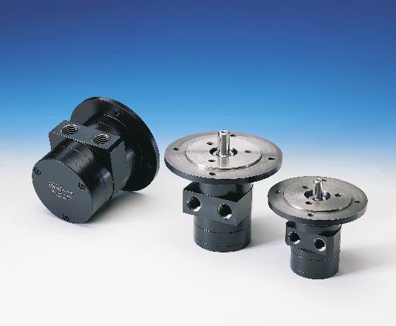
4 Air otors 1V-A Compressed air connection Spring loaded, lubrication-free vanes as standard. Keyed output shaft ainted cast iron housing Basic motor With helical gear With worm gear With planetary gear Air otors, Series 1V-A 1V-A is a range of reversible air motors intended for heavy and demanding applications. The motor housings are made from painted cast iron, and the components sealed to permit operation in damp and dirty environments. The range contains three different sizes, 1V-A160, 1V-A260 and 1V-A360, with power ratings of, 2 or 3 Watts. The basic motors can be supplied with built-in gearboxes, either planetary, helical or worm drive, to provide the correct speed of rotation and torque, and the correct installation mountings. Basic motor All pneumatic motors are equipped with spring loaded vanes as standard, which gives the motors very good starting and low speed running characteristics. They are also equipped with vanes for intermittent lube-free operation as standard. 100% lubrication-free vanes are obtainable as options. The simple construction of the motors makes them very reliable, with long service life and they are easy to service. otors with planetary gears A 1V-A combined with a planetary gear has small installation dimensions, low weight in relation to performance, free installation position, flange mounting as standard, in line output shaft and high efficiency. They are available with shaft speeds ranging from 95 rpm to 1 rpm, with torques ranging from 16 Nm to 160 Nm. otors with helical gears A 1V-A combined with a helical gear has high efficiency, simple installation with flange or foot, and competitive pricing. They are available with shaft speeds ranging from 25 rpm to 1050 rpm, with torques ranging from 23 Nm to 1 Nm. Oil-bath gears mean that the installation position must be decided beforehand. The installation position governs the amount of oil in the gear and the location of filling and drain plugs. otors with worm gears A 1V-A combined with a worm drive gear has the following characteristics: gearboxes with high gear ratios are self-locking, which means that they can be used to maintain the output shaft in position, simple installation with the flange on the left or right sides or with a foot, small installation dimensions and competitive pricing. They are available with shaft speeds ranging from 62 rpm to 500 rpm, with torques ranging from 38 Nm to 670 Nm. Oil-bath gears mean that the installation position must be decided beforehand. The installation position governs the amount of oil in the gear and the location of filling and drain plugs. roducts specially designed for mobile applications 4
5 Air otors 1V-A Air motors have much smaller installation dimensions than corresponding electric motors. Air motors can be stopped and started continually without damage. Air motors can be loaded until they stall, without damage. They are designed to be able to withstand the toughest heat, vibration, impact etc. The simple design principle of air motors make them very easy to service. The weight of an air motor is several times less than corresponding electric motors. The motors are reversible as standard. Air motors can be used in the harshest environments. The reliability of air motors is very high, thanks to the design and the low number of moving parts. 5
6 Air otors 1V-A rinciples of air motor function Torque, power and air consumption graphs [%] Q [%], [%] Q Inlet, left Outlet 1 Outlet Inlet, right n [%] Rotor cylinder 2 Rotor 3 Vanes 4 Spring 5 End piece with bearing There are a number of designs of air motor. arker neumatic has chosen to use the vane rotor design, because of its simple design and reliable operation. The small external dimensions of vane motors make them suitable for all applications. The principle of the vane motor is that a rotor with a number of vanes is enclosed in a rotor cylinder. The motor is supplied with compressed air through one connection and air escapes from the other connection. To give reliable starting, the springs press the vanes against the rotor cylinder. The air pressure always bears at right angles against a surface. This means that the torque of the motor is a result of the vane surfaces and the air pressure. = power = torque Q = air consumption n = speed The performance characteristics of each motor are shown in a family of curves as above, from which torque, power and air consumption can be read off as a function of speed. ower is zero when the motor is stationary and also when running at free speed (100%) with no load. aximum power (100%) is normally developed when the motor is driving a load at approximately half the free speed (50%). Torque at free speed is zero, but increases as soon as a load is applied, rising linearly until the motor stalls. As the motor can then stop with the vanes in various positions, it is not possible to specify an exact torque. However, a minimum starting torque is shown in all tables. Air consumption is greatest at free speed, and decreases with decreasing speed, as shown in the above diagram. 6
7 Air otors 1V-A Correction diagrams Speed regulation Correction factor 1,3 1,2 1,1 1,0 0,9 = f (p) = f (p) Q = f (p) n = f (p) Supply throttling, non-reversible motor Supply throttling, reversible motor Exhaust throttling, reversible motor 0,8 0,7 Torque curve change caused by throttling 0,6 0,5 0,4 0, p [bar] ressure regulation at motor inlet = power = torque Q = air consumption n = speed Torque curve change caused by pressure change All catalogue data and curves are specified at a supply pressure of 6 bar to the motor. This diagram shows the effect of pressure on speed, specified torque, power and air consumption. Start off on the curve at the pressure used and then look up to the lines for power, torque and air consumption. Read off the correction factor on the Y axis for each curve and multiply this by the specified catalogue data in the table, or data read from the torque and power graphs. Example: at 4 bar supply pressure, the power is only 0.55 x power at 6 bar supply pressure. This example shows how strongly power falls if supply pressure is reduced. You must therefore ensure that the motor is supplied through pipes of sufficient diameter to avoid pressure drop. Throttling The most common way to reduce the speed of a motor is to install a flow control valve in the air inlet. When the motor is used in applications where it must reverse and it is necessary to restrict the speed in both directions, flow control valves with by-pass should be used in both directions. Inlet throttling If the inlet air is restricted, the air supply is restricted and the free speed of the motor falls, but there is full pressure on the vanes at low speeds. This means that we get full torque from the motor at low speeds despite the low air flow. Since the torque curve becomes steeper, this also means that we get a lower torque at any given speed than would be developed at full air flow. ressure regulation The speed and torque can also be regulated by installing a pressure regulator in the inlet pipe. This means that the motor is constantly supplied with air at lower pressure, which means that when the motor is braked, it develops a lower torque on the output shaft. In brief: Inlet throttling gives reduced speed in one direction but maintains torque when braked. The torque curve becomes steeper. ressure regulation in the inlet cuts torque when the motor is braked, and also reduced speed. The torque curve is moved parallel. 7
8 Air otors Direction of motor rotation Outlet Inlet, left-hand rotation Inlet, right-hand rotation Outlet 1V-A Choice of components for air supply Since the supply pressure at the air motor inlet port is of considerable importance for obtaining the power, speed and torque quoted in the catalogue, the recommendations below should be observed. The direction of rotation of reversible motors is obtained by supplying inlet L or inlet R with compressed air. The motor can be stopped and started continually without damage occurring. Air supply The following data must be complied with: Supply pressure: 7 bar Regulator pressure setting: 6.7 bar ipe length between air treatment unit and valve: max. 1 m ipe length valve and air motor: max. 2 m The pressure drop through the air preparation unit, pipe, valve and pipe means that 6 bar pressure is obtained at the motor supply port. lease refer to the correction diagram on page 7, which shows what lower supply pressure means for power, speed and torque. Shut-off, filtering, pressure regulation and control valve 5 3 Reversible motor with 5/3 control valve Air motor 1V-A160 1V-A260 1V-A360 Air flow required, Nl/s in pipe ID, inlet, mm in pipe ID, outlet, mm Recommended air treatment unit axi odular G1/2 and G3/4 Reversible motor with two 3/2 control valves The air with which the motor is supplied must be filtered and regulated. Directional valves are needed to provide it with air, to get the motor to rotate when we want it to. These valves can be equipped with several means of actuation, such as electric, manual and pneumatic control. When the motor is used in a nonreversible application, it is sufficient to use a 2/2 or 3/2 valve for supply. Either one 5/3 or two 3/2 valves are needed for a reversible motor, to ensure that the motor receives compressed air and the residual air outlet is vented. A flow control valve can be installed in the supply pipe to regulate the motor speed if the motor is not used as a reversible motor. One flow control valve with by-pass is needed to regulate each direction of rotation if the motor is used as a reversible motor. The built-in check valve will then allow air from the residual air outlet to escape through the outlet port in the control valve. The compressed air supply must have sufficiently large pipes and valves to give the motor maximum power. The motor needs 6 bar at the supply port all the time. A reduction of pressure to 5 bar reduces the power developed to 77%, and to 55% at 4 bar. Recommended valve series Valves with connections in valve housing VE42/43 VE82/83 Valves with connections in base plate Apollo, size 3 Flexflow VG45 Flexflow VE45 8
9 Air otors 1V-A Silencing Exhaust silencer Lubrication and service life Noise reduction at 5.7 bar working pressure Open port 1/8" 1/2" 3/8" 1/4" Oil and oil mist are things which one tries to avoid to get the best possible working environment. In addition, purchasing, installation and maintenance of oil mist equipment costs money and, above all, time to achieve optimum lubrication effect. Users in all industries now try to avoid using components which have to be lubricated. The 1V-A motor is equipped with vanes for intermittent operation as standard, which is the most common application of air motors. The motor is also available with optional hard vanes for continuous lubrication-free operation (option C ). Central silencer Octave band frequency in khz Noise level Noise level [dba] Expected service life of 1V-A motors Air treatment Filtering 40 µm or better Dew point +3 to +4 C Air temperature +20 C Intermittent lubrication-free operation of 1V-A standard motors Duty cycle 70% ax. duration of intermittent use 15 minutes Filtering 40 µm app. 750 hours operation Filtering 5 µm app. 1,000 hours operation " Open pipe 1/2" Open pipe ESC B-2 ESC B Flow [l/s] The noise from a air motor consists of both mechanical noise and a pulsating noise from the air flowing out of the outlet. The installation of the motor has a considerable effect on mechanical noise. It should be installed so that no mechanical resonance effects can occur. The outlet air creates a noise level which can amount to 115 db(a) if the air is allowed to exhaust freely into the atmosphere. Various types of exhaust silencers are used to reduce this level. The most common type screws directly onto the exhaust port of the motor. Since the motor function causes the exhaust air to pulsate, it is a good idea to allow the air to exhaust into some kind of chamber first, which reduces the pulsations before they reach the silencer. The device which gives best silencing is to connect a soft plastic hose to a large central silencer which has the largest possible area, to reduce the speed of the out-flowing air as far as possible. Flow [l/s] Continuous operation of 1V-A standard motors, with lubrication Oil volume 1 drop oil/nm 3 Filtering 40 µm app. 1,000 hours operation Filtering 5 µm app. 2,000 hours operation Continuous lubrication-free operation of 1V-A motors equipped with hard vanes (option C ) Filtering 40 µm app. 750 hours operation Filtering 5 µm app. 1,000 hours operation lease refer to page 39 for service kits. NOTE! Remember that a silencer which is too small or is blocked, generates back pressure on the outlet side of the motor, which reduces the motor power. 9
10 Air otors Choice of air motor, general The motor to be used should be selected by starting with the torque needed at a specific spindle speed. In other words, to choose the right motor, you have to know the required speed and torque. Since maximum power is reached at half the motor s free speed, the motor should be chosen so that the point aimed at is as close as possible to the maximum power of the motor. The design principle of the motor means that higher torque is generated when it is braked, which tends to increase the speed, etc. This means that the motor has a kind of speed self-regulation function built in. Use the following graph to choose the correct motor size and the correct type of gear as appropriate. The graph contains the points for the maximum torque of each motor at maximum power. ut in your point on the graph and select a marked point above and to the right of the point you need. 1V-A Then check the characteristic graph of each motor to find more accurate technical data. Always select a motor where the data required is in the grey field. Also use the correction diagram to see what it would mean to use different air supply pressures with the motor. Tip: Select a motor which is slightly too fast and powerful, regulate its speed and torque with a pressure regulator and/or restriction to achieve the optimum working point. Choice of motors with planetary gears Torque at maximum power (Nm) ,0 3, Speed at maximum power (rpm) lanetary gears are characterised by high efficiency, low moment of inertia and can offer high gear ratios. The output shaft is always in the centre of the gearbox. Small installation dimensions relative to the torque provided. The gears are lubricated by grease, which means that it can be installed in all conceivable positions. Small installation dimensions Free installation position Simple flange installation Low weight Output shaft in centre High efficiency Air motors in diagram above 1V-A160A0900, please refer to page V-A160B0120, please refer to page V-A160B0060, please refer to page V-A160B0019, please refer to page V-A160B0010, please refer to page 16 1V-A260A0700, please refer to page V-A260B0120, please refer to page V-A260B0060, please refer to page V-A260B0019, please refer to page 16 1V-A360A0, please refer to page V-A360B0096, please refer to page V-A360B0048, please refer to page 16 10
11 Air otors 1V-A Choice of motors with helical gears Torque at maximum power (Nm) ,0 3, Speed at maximum power (rpm) Helical gears are characterised by high efficiency. Several reduction stages permit relatively high gear ratios. Central output shaft and simple installation with flange or foot. Oil-bath gearboxes mean that the installation position must be decided in advance. The installation position determines the volume of oil in the gearbox and location of oil filling and drain plugs. High efficiency Simple flange or foot installation Relatively low price Installation position must be chosen in advance Higher weight than planetary or worm drive gears. Air motors in diagram above 1V-A160A0900, please refer to page V-A , Choose installation below 2 1V-A , Choose installation below 3 1V-A , Choose installation below 4 1V-A , Choose installation below 5 1V-A , Choose installation below 6 1V-A , Choose installation below 1V-A260A0700, please refer to page V-A , Choose installation below 2 1V-A , Choose installation below 3 1V-A , Choose installation below 4 1V-A , Choose installation below 5 1V-A , Choose installation below 6 1V-A , Choose installation below 1V-A360A0, please refer to page V-A , Choose installation below 2 1V-A , Choose installation below 3 1V-A , Choose installation below 4 1V-A , Choose installation below 5 1V-A , Choose installation below 6 1V-A , Choose installation below Installation, flange mounting lease refer to page 18 Installation, foot mounting lease refer to page 19 11
12 Air otors 1V-A Choice of motors with worm gears Torque at maximum power (Nm) ,0 3, Speed at maximum power (rpm) Worm gears are characterised by relatively simple technical construction, with a worm and pinion. This can give a large gear ratio and small dimensions. The efficiency of a worm drive gear is considerably lower than for planetary or helical gears. The design principle of worm drive gears makes them self-locking at higher gear ratios (the output shaft is locked ). The output shaft comes out at an angle of 90 to the motor spindle. Installation is simple, with a flange on the left or right side, or with a foot. The gearbox is equipped as standard with a hollow output shaft with a key slot. Loose shafts with key can put the output shaft on the right, left, or on both sides. Oil-bath gearboxes mean that the installation position must be decided in advance. The installation position determines the volume of oil in the gearbox and location of oil filling and drain plugs. Low weight in relation to gear ratio Non-reversible at high gear ratios Relatively low price Relatively low efficiency Installation position must be decided in advance Output shaft at 90 to motor spindle Air motors in diagram above 1V-A160A0900, please refer to page V-A , Choose installation below 2 1V-A , Choose installation below 3 1V-A , Choose installation below 4 1V-A , Choose installation below 1V-A260A0700, please refer to page V-A , Choose installation below 2 1V-A , Choose installation below 3 1V-A , Choose installation below 4 1V-A , Choose installation below 1V-A360A0, please refer to page V-A , Choose installation below 2 1V-A , Choose installation below 3 1V-A , Choose installation below 4 1V-A , Choose installation below Installation, foot mounting lease refer to page 24 Installation, flange mounting, left-hand lease refer to page 22 Installation, flange mounting, right-hand lease refer to page 23 12
13 Air otors Technical data Working pressure ax 7 bar Working temperature -30 C to +100 C edium 40 µm filtered air with or without oil mist Design data Basic motor Robust design with few components Spring loaded vanes as standard give good starting and low speed characteristics Keyed output shaft Reversible operation lanetary gear recision made gears with efficiency over 95% Sealed, permanently grease lubrication gives free installation position Compact installation and low weight Central output shaft Helical gear Two versions available, with flange or foot High efficiency, 90 to 95% Oil-bath gearboxes mean that the installation position must be decided in advance. The installation position determines the volume of oil in the gearbox and location of oil filling and drain plugs. Worm gear Available in three versions, for installation with left-hand flange, righthand flange or foot mounting. Compact size and low weight Self-locking in higher ratios Output shaft at 90 angle to motor spindle Hollow output shaft with key slot. Single-ended or "through" twin shaft as options. Oil-bath gearboxes mean that the installation position must be decided in advance. The installation position determines the volume of oil in the gearbox and location of oil filling and drain plugs. aterial specification 1V-A Basic motor Housing Cast iron, synthetic paint, black Spindle, rotor High grade steel Key Hardened steel O-rings Nitrile rubber, NBR Screws Zinc-coated steel lanetary gear Housing Alloy steel, synthetic paint, black Shaft High grade steel Key Hardened steel Shaft seals Nitrile rubber, NBR Screws Zinc-coated steel Helical gear Housing Aluminium or cast iron, synthetic paint, black Shaft High grade steel Key Hardened steel Shaft seals Nitrile rubber, NBR Screws Zinc-coated steel Worm drive gear Housing Aluminium or cast iron, synthetic paint, black Shaft High grade steel Key Hardened steel inion Chill cast phosphor bronze Worm Alloyed, hardened steel Shaft seals Nitrile rubber, NBR Screws Zinc-coated steel Accessories Keyed shafts for worm gear Shaft High grade steel Key Hardened steel Table and diagram data All values are typical values, with a tolerance of ±10% Options Other variants on request. 13
14 Air otors 1V-A Order key 1 V - A E B 6 otor size 160 W W W A B D Function Basic motor without gearbox, keyed shaft With planetary gear, keyed shaft With helical gear, flange, keyed shaft Free/max speed per min Installation position - Free installation Horizontal installation B3 Installation position B3 B5 Installation position B5 B6 Installation position B6 1V-A Air motor family Large vane motor, reversible ossible combinations lease refer to pages 15 to 24 E F G H With helical gear, foot, keyed shaft With worm gear, flange left, hollow shaft with key slot With worm gear, flange right, hollow shaft with key slot With worm gear, foot, hollow shaft with key slot Optional functions 0 Standard C Lubrication-free, continuous operation B7 B8 V1 V3 V5 V6 Installation position B7 Installation position B8 Vertical installation Installation position V1 Installation position V3 Installation position V5 Installation position V6 A: Free installation positions, basic motor lease refer to page 15 B: Free installation positions, planetary gear lease refer to page 16 F: Installation pos., worm gear and flange, left-hand lease refer to page 22 B3 V6 V5 D: Free installation positions, helical gear and flange lease refer to page 18 B8 B6 B7 B5 V1 V3 G: Installation pos., worm gear and flange, right-hand lease refer to page 23 B3 V6 V5 E: Installation positions, helical gear and foot lease refer to page 19 V5 V6 B8 B6 B7 H: Installation positions, worm gear and foot lease refer to page 24 B3 V6 V5 B3 B8 B7 B6 B8 B6 B7 14
15 Air otors, Basic motor 1V-A NOTE! All technical data are based on a working pressure of 6 bar. A: Basic motor with keyed shaft ax Free Speed Torque in Air consump- Con- in pipe Weight Order code power speed* at max at max start tion at max nec- ID inlet/ power power torque power tion outlet kw rpm rpm Nm Nm l/s mm Kg Series 1V-A160 1, ,3 5,0 32 G1/2 19/19 4,2 1V-A160A0900 Series 1V-A260 2, ,1 11,0 60 G3/4 19/25 7,9 1V-A260A0700 Series 1V-A360 3, ,5 17,0 80 G1 22/32 16,0 1V-A360A0 * Idling speed 1V-A160A0900, torque [Nm], power [W] 1V-A260A0700, torque [Nm], power [W] 1V-A360A0, torque [Nm], power [W] 8,0 6, ,0 12, ,0 18, ,0 8,0 12, ,0 4,0 6, n, speed [rpm] n, speed [rpm] n, speed [rpm] Working range of motor ermitted shaft loadings, please refer to page 37 Dimensions, please refer to pages
16 Air otors, lanetary gear 1V-A NOTE! All technical data are based on a working pressure of 6 bar. B: otor with planetary gear, flange mounting. Free installation position ax ax Speed Torque in ax Air consump- Con- in pipe Weight Order code power speed at max at max start permitted tion at max nec- ID inlet/ power power torque torque power tion outlet kw rpm rpm Nm Nm Nm l/s mm Kg Series 1V-A160 1, G1/2 19/19 8,3 1V-A160B0120 1, G1/2 19/19 8,3 1V-A160B0060 1, G1/2 19/19 15,4 1V-A160B0019 1, G1/2 19/19 15,4 1V-A160B0010 Series 1V-A260 2, G3/4 19/25 12,0 1V-A260B0120 2, G3/4 19/25 12,0 1V-A260B0060 2, G3/4 19/25 13,0 1V-A260B0019 Series 1V-A360 3, G1 22/32 25,5 1V-A360B0096 3, G1 22/32 25,5 1V-A360B0048 ermitted shaft loadings, please refer to page 37 Dimensions, please refer to page 30 16
17 Air otors, anetary gear 1V-A 1V-A160B0120, torque [Nm], power [W] 1V-A160B0060, torque [Nm], power [W] 1V-A160B0019, torque [Nm], power [W] ax permitted speed ax permitted speed n, speed [rpm] n, speed [rpm] n, speed [rpm] ax permitted speed V-A160B0010, torque [Nm], power [W] 1V-A260B0120, torque [Nm], power [W] 1V-A260B0060, torque [Nm], power [W] ax permitted speed ax permitted speed n, speed [rpm] n, speed [rpm] n, speed [rpm] ax permitted speed V-A260B0019, torque [Nm], power [W] 1V-A360B0096, torque [Nm], power [W] 1V-A360B0048, torque [Nm], power [W] ax permitted speed ax permitted speed 1 n, speed [rpm] n, speed [rpm] n, speed [rpm] ax permitted speed Working range of motor 17
18 Air otors, Helical gear 1V-A NOTE! All technical data are based on a working pressure of 6 bar. D: otor with helical gear, flange mounting ax ax Speed Torque in ax Air consump- Con- in pipe Weight Order code power speed at max at max start permitted tion at max nec- ID inlet/ power power torque torque power tion outlet kw rpm rpm Nm Nm Nm l/s mm Kg Series 1V-A160 1, G1/2 19/19 9,5 1V-A160D0066 1, G1/2 19/19 11,5 1V-A160D0032 1, G1/2 19/19 14,0 1V-A160D0014 1, G1/2 19/19 29,0 1V-A160D0008 1, G1/2 19/19 42,5 1V-A160D0004 1, G1/2 19/19 62,5 1V-A160D0003 Series 1V-A260 2, G3/4 19/25 13,8 1V-A260D0080 2, G3/4 19/25 15,8 1V-A260D0052 2, G3/4 19/25 18,5 1V-A260D0025 2, G3/4 19/25 34,0 1V-A260D0011 2, G3/4 19/25 47,0 1V-A260D0006 2, G3/4 19/25 67,0 1V-A260D0003 Series 1V-A360 3, G1 22/32 24,5 1V-A360D0105 3, G1 22/32 24,5 1V-A360D0052 3, G1 22/32 42,5 1V-A360D0025 3, G1 22/32 54,5 1V-A360D0013 3, G1 22/32 75,5 1V-A360D0006 3, G1 22/32 149,5 1V-A360D0003 Note! specify installation position in the order no. as in the illustrations below. Example: 1V-A160D0066B5 D: Installation positions, helical gears and flange B5 V1 V3 Torque and power graphs, please refer to pages ermitted shaft loadings, please refer to page 38 Dimensions, please refer to pages 31 18
19 Air otors, Helical gear 1V-A E: otor with helical gear, foot mounting ax ax Speed Torque in ax Air consump- Con- in pipe Weight Order code power speed at max at max start permitted tion at max nec- ID inlet/ power power torque torque power tion outlet kw rpm rpm Nm Nm Nm l/s mm Kg Series 1V-A160 1, G1/2 19/19 9,8 1V-A160E0066 1, G1/2 19/19 11,5 1V-A160E0032 1, G1/2 19/19 14,5 1V-A160E0014 1, G1/2 19/19 31,2 1V-A160E0008 1, G1/2 19/19 44,5 1V-A160E0004 1, G1/2 19/19 65,2 1V-A160E0003 Series 1V-A260 2, G3/4 19/25 13,8 1V-A260E0080 2, G3/4 19/25 15,8 1V-A260E0052 2, G3/4 19/25 18,5 1V-A260E0025 2, G3/4 19/25 34,0 1V-A260E0011 2, G3/4 19/25 47,0 1V-A260E0006 2, G3/4 19/25 67,0 1V-A260E0003 Series 1V-A360 3, G1 22/32 24,5 1V-A360E0105 3, G1 22/32 24,5 1V-A360E0052 3, G1 22/32 42,5 1V-A360E0025 3, G1 22/32 54,5 1V-A360E0013 3, G1 22/32 75,5 1V-A360E0006 3, G1 22/32 149,5 1V-A360E0003 Note! specify installation position in the order no. as in the illustrations below. Example: 1V-A160E0066V5 E: Installation positions, helical gears and flange V5 V6 B3 B8 B7 B6 Torque and power graphs, please refer to pages ermitted shaft loadings, please refer to page 38 Dimensions, please refer to pages 32 19
20 Air otors, Helical gear 1V-A 1V-A160D0066 1V-A160E0066, torque [Nm], power [W] 1V-A160D0032 1V-A160E0032, torque [Nm], power [W] 1V-A160D0014 1V-A160E0014, torque [Nm], power [W] ax permitted speed ax permitted speed n, speed [rpm] n, speed [rpm] n, speed [rpm] ax permitt. torque ax permitted speed V-A160D0008 1V-A160E0008, torque [Nm], power [W] ax permitted speed n, speed [rpm] 1V-A160D0004 1V-A160E0004, torque [Nm], power [W] ax permitt. torque ax permitted speed 1 1 1V-A160D0003 1V-A160E0003, torque [Nm], power [W] ax permitt. torque n, speed [rpm] n, speed [rpm] ax permitted speed 1 1 1V-A260D0080 1V-A260E0080, torque [Nm], power [W] n, speed [rpm] 1V-A260D0052 1V-A260E0052, torque [Nm], power [W] 1V-A260D0025 1V-A260E0025, torque [Nm], power [W] ax permitted torque ax permitted torque ax permitted torque ax permitted speed ax permitted speed ax permitted speed n, speed [rpm] n, speed [rpm] Working range of motor 20
21 Air otors, Helical gear 1V-A 1V-A260D0011 1V-A260E0011, torque [Nm], power [W] 1V-A260D0006 1V-A260E0006, torque [Nm], power [W] 1 1V-A260D0003 1V-A260E0003, torque [Nm], power [W] V-A360D0105 1V-A360E0105, torque [Nm], power [W] ax permitted torque ax permitted speed n, speed [rpm] n, speed [rpm] n, speed [rpm] ax permitted speed V-A360D0052 1V-A360E0052, torque [Nm], power [W] ax permitt. torque ax permitted torque ax permitted speed ax permitted speed 1V-A360D0025 1V-A360E0025, torque [Nm], power [W] n, speed [rpm] n, speed [rpm] n, speed [rpm] ax permitted torque ax permitted speed ax permitted speed V-A360D0013 1V-A360E0013, torque [Nm], power [W] 1V-A360D0006 1V-A360E0006, torque [Nm], power [W] 1V-A360D0003 1V-A360E0003, torque [Nm], power [W] ax permitted torque ax permitted speed ax permitt. torque ax permitted speed n, speed [rpm] n, speed [rpm] n, speed [rpm] ax permitted speed Working range of motor 21
22 Air otors, Worm gear 1V-A NOTE! All technical data are based on a working pressure of 6 bar. F: otor with worm gear, flange mounting left-hand ax ax Speed Torque in ax Types Air consump- Con- in pipe Weight Order code power speed at max at max start permitted of tion at max nec- ID inlet/ power power torque torque self- power tion outlet kw 1/min 1/min Nm Nm Nm locking l/s mm Kg Series 1V-A160 1, G1/2 19/19 7,2 1V-A160F0043 1, G1/2 19/19 10,2 1V-A160F0020 1, G1/2 19/19 20,5 1V-A160F0010 1, G1/2 19/19 20,5 1V-A160F0008 Series 1V-A260 2, G3/4 19/25 11,0 1V-A260F0050 2, G3/4 19/25 21,0 1V-A260F0022 2, G3/4 19/25 21,0 1V-A260F0013 2, G3/4 19/25 57,0 1V-A260F0008 Series 1V-A360 3, G1 22/32 22,5 1V-A360F0050 3, G1 22/32 33,0 1V-A360F0022 3, G1 22/32 49,0 1V-A360F0013 3, G1 22/32 65,5 1V-A360F0006 Note! specify installation position in the order no. as in the illustrations below. Example: 1V-A160F0066B3 F: Installation positions, worm gear and flange, left-hand B3 V6 V5 Self-locking Dynamic self-locking means that the force acting on the output shaft of the gear can not turn the gear further when the air motor is stopped. Dynamic self-locking is only possible when the gear ratio is high, and at low speeds. None of our worm drive gears are completely self-locking in dynamic conditions. Static self-locking means that the force acting on the output shaft of the gear can not begin to turn the shaft. When loads with considerable momentum are driven, it is necessary to have a braking time sufficient to stop the gearbox from being overloaded. It is extremely important that the maximum permitted torque is not exceeded. B8 B6 B7 Tip: Braking of the air motor can be arranged by either slowly restricting the air supply to the motor until it is completely shut off, or by slowly reducing the supply pressure to zero. Torque and power graphs, please refer to pages Types of Self-locking 1. Static, not self-locking 2. Static, self-locking - quicker return under vibration - not dynamically self-locking 3. Static, self-locking - return only possible under vibration - good dynamic self-locking ermitted shaft loadings, please refer to page 38 Dimensions, please refer to pages 33 NOTE! As standard, the motor has a hollow shaft with key slot. Single-ended and double-ended shafts with keys are available as accessories, please refer to page 25. Important! Since it is practically impossible to guarantee total self-locking, an external brake must be used to guarantee that vibration can not cause an output shaft to move. 22
23 Air otors, Worm gear 1V-A G: otor with worm gear, flange mounting, right-hand ax ax Speed Torque in ax Types Air consump- Con- in pipe Weight Order code power speed at max at max start permitted of tion at max nec- ID inlet/ power power torque torque self- power tion outlet kw 1/min 1/min Nm Nm Nm locking l/s mm Kg Series 1V-A160 1, G1/2 19/19 7,2 1V-A160G0043 1, G1/2 19/19 10,2 1V-A160G0020 1, G1/2 19/19 20,5 1V-A160G0010 1, G1/2 19/19 20,5 1V-A160G0008 Series 1V-A260 2, G3/4 19/25 11,0 1V-A260G0050 2, G3/4 19/25 21,0 1V-A260G0022 2, G3/4 19/25 21,0 1V-A260G0013 2, G3/4 19/25 57,0 1V-A260G0008 Series 1V-A360 3, G1 22/32 22,5 1V-A360G0050 3, G1 22/32 33,0 1V-A360G0022 3, G1 22/32 49,0 1V-A360G0013 3, G1 22/32 65,5 1V-A360G0006 Note! specify installation position in the order no. as in the illustrations below. Example: 1V-A160G0066B3 G: Installation positions, worm gear and flange, righthand B3 V6 V5 Self-locking Dynamic self-locking means that the force acting on the output shaft of the gear can not turn the gear further when the air motor is stopped. Dynamic self-locking is only possible when the gear ratio is high, and at low speeds. None of our worm drive gears are completely self-locking in dynamic conditions. Static self-locking means that the force acting on the output shaft of the gear can not begin to turn the shaft. When loads with considerable momentum are driven, it is necessary to have a braking time sufficient to stop the gearbox from being overloaded. It is extremely important that the maximum permitted torque is not exceeded. B8 B6 B7 Tip: Braking of the air motor can be arranged by either slowly restricting the air supply to the motor until it is completely shut off, or by slowly reducing the supply pressure to zero. Torque and power graphs, please refer to pages Types of Self-locking 1. Static, not self-locking 2. Static, self-locking - quicker return under vibration - not dynamically self-locking 3. Static, self-locking - return only possible under vibration - good dynamic self-locking ermitted shaft loadings, please refer to page 38 Dimensions, please refer to pages 34 NOTE! As standard, the motor has a hollow shaft with key slot. Single-ended and double-ended shafts with keys are available as accessories, please refer to page 25. Important! Since it is practically impossible to guarantee total self-locking, an external brake must be used to guarantee that vibration can not cause an output shaft to move. 23
24 Air otors, Worm gear 1V-A NOTE! All technical data are based on a working pressure of 6 bar. H: otor with worm gear, foot mounting ax ax Speed Torque in ax Types Air consump- Con- in pipe Weight Order code power speed at max at max start permitted of tion at max nec- ID inlet/ power power torque torque self- power tion outlet kw 1/min 1/min Nm Nm Nm locking l/s mm Kg Series 1V-A160 1, G1/2 19/19 7,2 1V-A160H0043 1, G1/2 19/19 10,2 1V-A160H0020 1, G1/2 19/19 20,5 1V-A160H0010 1, G1/2 19/19 20,5 1V-A160H0008 Series 1V-A260 2, G3/4 19/25 11,0 1V-A260H0050 2, G3/4 19/25 21,0 1V-A260H0022 2, G3/4 19/25 21,0 1V-A260H0013 2, G3/4 19/25 57,0 1V-A260H0008 Series 1V-A360 3, G1 22/32 22,5 1V-A360H0050 3, G1 22/32 33,0 1V-A360H0022 3, G1 22/32 49,0 1V-A360H0013 3, G1 22/32 65,5 1V-A360H0006 Note! specify installation position in the order no. as in the illustrations below. Example: 1V-A160H0066B3 H: Installation positions, worm gear and foot B3 V6 V5 Self-locking Dynamic self-locking means that the force acting on the output shaft of the gear can not turn the gear further when the air motor is stopped. Dynamic self-locking is only possible when the gear ratio is high, and at low speeds. None of our worm drive gears are completely self-locking in dynamic conditions. Static self-locking means that the force acting on the output shaft of the gear can not begin to turn the shaft. When loads with considerable momentum are driven, it is necessary to have a braking time sufficient to stop the gearbox from being overloaded. It is extremely important that the maximum permitted torque is not exceeded. B8 B6 B7 Tip: Braking of the air motor can be arranged by either slowly restricting the air supply to the motor until it is completely shut off, or by slowly reducing the supply pressure to zero. Torque and power graphs, please refer to pages Types of Self-locking 1. Static, not self-locking 2. Static, self-locking - quicker return under vibration - not dynamically self-locking 3. Static, self-locking - return only possible under vibration - good dynamic self-locking ermitted shaft loadings, please refer to page 38 Dimensions, please refer to pages 35 NOTE! As standard, the motor has a hollow shaft with key slot. Single-ended and double-ended shafts with keys are available as accessories, please refer to page 25. Important! Since it is practically impossible to guarantee total self-locking, an external brake must be used to guarantee that vibration can not cause an output shaft to move. 24
25 Air otors, Worm gear 1V-A Shaft with keys for 1V-A with worm gear otor type Single-ended shaft Weight Double-ended shaft Weight Order code kg Order code kg Serie 1V-A160 1V-A , ,77 1V-A , ,95 1V-A , ,00 1V-A , ,00 Serie 1V-A260 1V-A , ,77 1V-A , ,00 1V-A , ,00 1V-A , ,10 Serie 1V-A360 1V-A , ,95 1V-A , ,00 1V-A , ,60 1V-A , ,10 otor with worm gear (functions F, G and H) Installation position, optional Dimensions, please refer to page 36 25
26 Air otors, Worm gear 1V-A 1V-A160F0043 1V-A160G0043 1V-A160H0043, torque [Nm], power [W] ax permitted speed n, speed [rpm] 1V-A160F0020 1V-A160G0020 1V-A160H0020, torque [Nm], power [W] ax permitted speed 1 1 1V-A160F0010 1V-A160G0010 1V-A160H0010, torque [Nm], power [W] n, speed [rpm] n, speed [rpm] ax permitted speed 1 1 1V-A160F0008 1V-A160G0008 1V-A160H0008, torque [Nm], power [W] ax permitted speed 1 1 1V-A260F0050 1V-A260G0050 1V-A260H0050, torque [Nm], power [W] ax permitted torque ax permitted speed 1V-A260F0022 1V-A260G0022 1V-A260H0022, torque [Nm], power [W] n, speed [rpm] n, speed [rpm] n, speed [rpm] ax permitted speed V-A260F0013 1V-A260G0013 1V-A260H0013, torque [Nm], power [W] 1V-A260F0008 1V-A260G0008 1V-A260H0008, torque [Nm], power [W] ax permitted torque ax permitted speed n, speed [rpm] n, speed [rpm] ax permitted speed Working range of motor 26
27 Air otors, Worm gear 1V-A 1V-A360F0050 1V-A360G0050 1V-A360H0050, torque [Nm], power [W] 1V-A360F0022 1V-A360G0022 1V-A360H0022, torque [Nm], power [W] 1V-A360F0013 1V-A360G0013 1V-A360H0013, torque [Nm], power [W] ax permitted torque ax permitted speed ax permitted speed n, speed [rpm] n, speed [rpm] n, speed [rpm] ax permitted speed V-A360F0006 1V-A360G0006 1V-A360H0006, torque [Nm], power [W] ax permitted speed n, speed [rpm] Working range of motor 27
28 Air otors 1V-A Dimensions (mm) otor 1V-A160A0900 Flange IEC 71 A B Ø160 Ø110f7 Ø14k , ,5 G1/2 44 Ø80 Ø92 Ø112 Ø9 5h9 Ø130 otor 1V-A260A0700 Flange IEC 80 A B5 102 Ø11 k6 28 Ø Ø19 8 Ø130 Ø f h G3/ , , Ø165 81
29 Air otors 1V-A Dimensions (mm) otor 1V-A360A0 Flange IEC 90 A B5 29
30 Air otors 1V-A Dimensions (mm) otor with planetary gear C8 C9 C5 A3 B7 C2 h9 B5 B4 h6 B3 B2 h6 C6 C1 B7 C7 A2 A5 A4 A6 A7 A8 A9 C4 C3 B1 A1 D1 D2 B8 D3 Order code A1 A2 A3 A4 A5 A6 A7 A8 A9 B1 B2 B3 B4 B5 B6 1V-A160B , , , , V-A160B , , , , V-A160B , , , , V-A160B , , , , V-A260B , , , , V-A260B , , , , V-A260B , , , , V-A360B , , , , V-A360B , , , , Order code B7 B8 C1 C2 C3 C4 C5 C6 C7 C8 C9 D1 D2 D3 1V-A160B , G1/ V-A160B , G1/ V-A160B , G1/ V-A160B , G1/ V-A260B , G3/ V-A260B , G3/ V-A260B , G3/ V-A360B , G V-A360B , G
31 Air otors 1V-A Dimensions (mm) otor with helical gear, flange mounting A1 A5 A3 A6 A4 A2 A8 A9 A13 B2 B1 B4 B3 A7 C2 C1 UNI 6604 DIN 6885 A10 A11 A12 Lifting lug only fitted to 1V-A360D0003 C4 C3 Order code A1 A2 A3 A4 A5 A6 A7 A8 A9 A10 A11 A12 A13 B1 B2 B3 1V-A160D , , f , ,0 1V-A160D , , f , ,5 1V-A160D , , f , ,0 1V-A160D , , f , ,0 1V-A160D , , f , ,0 1V-A160D , , f , ,0 1V-A260D , , f , ,0 1V-A260D , , f , ,5 1V-A260D , , f , ,0 1V-A260D , , f , ,0 1V-A260D , , f , ,0 1V-A260D , , f , ,0 1V-A360D , , f , ,5 1V-A360D , , f , ,5 1V-A360D , , f , ,0 1V-A360D , , f , ,0 1V-A360D , , f , ,0 1V-A360D , , f , ,0 Order code B4 C1 C2 C3 C4 1V-A160D x6x30 22,5 8x19 20 h6 1V-A160D x7x40 28,0 8x19 25 h6 1V-A160D x7x50 33,0 10x22 30 h6 1V-A160D x8x60 38,0 10x22 35 h6 1V-A160D x8x70 43,0 12x28 40 h6 1V-A160D x9x90 53,5 16x36 50 h6 1V-A260D0080 6x6x30 22,5 8x19 20 h6 1V-A260D0052 8x7x40 28,0 8x19 25 h6 1V-A260D0025 8x7x50 33,0 10x22 30 h6 1V-A260D x8x60 38,0 10x22 35 h6 1V-A260D x8x70 43,0 12x28 40 h6 1V-A260D x9x90 53,5 16x36 50 h6 1V-A360D0105 8x7x40 28,0 8x19 25 h6 1V-A360D0052 8x7x40 28,0 8x19 25 h6 1V-A360D x8x60 38,0 10x22 35 h6 1V-A360D x8x70 43,0 12x28 40 h6 1V-A360D x9x90 53,5 16x36 50 h6 1V-A360D x14x110 85,0 20x42 80 h6 31
32 Air otors 1V-A Dimensions (mm) otor with helical gear, foot mounting A1 A2 A10 A3 A4 A5 B3 B1 B5 B4 A6 A7 A9 A8 C1 UNI 6604 DIN 6885 A11 A12 B2 C2 A13 Lifting lug only fitted to 1V-A360E0003 C4 C3 Order code A1 A2 A3 A4 A5 A6 A7 A8 A9 A10 A11 A12 A13 B1 B2 B3 1V-A160E , ,0 107, V-A160E , ,5 137, V-A160E , ,0 156, V-A160E , ,5 185, V-A160E , ,0, V-A160E , ,0 222, V-A260E , ,0 107, V-A260E , ,5 137, V-A260E , ,0 156, V-A260E , ,5 185, V-A260E , ,0, V-A260E , ,0 222, V-A360E , ,5 137, V-A360E , ,5 137, V-A360E , ,5 185, V-A360E , ,0, V-A360E , ,0 222, V-A360E , , Order code B4 B5 C1 C2 C3 C4 1V-A160E x6x30 22,5 8x19 20 h6 1V-A160E x7x40 28,0 8x19 25 h6 1V-A160E x7x50 33,0 10x22 30 h6 1V-A160E x8x60 38,0 10x22 35 h6 1V-A160E x8x70 43,0 12x28 40 h6 1V-A160E x9x90 53,5 16x36 50 h6 1V-A260E x6x30 22,5 8x19 20 h6 1V-A260E x7x40 28,0 8x19 25 h6 1V-A260E x7x50 33,0 10x22 30 h6 1V-A260E x8x60 38,0 10x22 35 h6 1V-A260E x8x70 43,0 12x28 40 h6 1V-A260E x9x90 53,5 16x36 50 h6 1V-A360E x7x40 28,0 8x19 25 h6 1V-A360E x7x40 28,0 8x19 25 h6 1V-A360E x8x60 38,0 10x22 35 h6 1V-A360E x8x70 43,0 12x28 40 h6 1V-A360E x9x90 53,5 16x36 50 h6 1V-A360E x14x110 85,0 20x42 80 h6 32
Air Motors. Series P1V-A
 aerospace climate control electromechanical filtration fluid & gas handling hydraulics pneumatics process control sealing & shielding Air otors Series Catalogue DE2555TCUK June 2011 Air otors Features
Vane Air Motors - P1V-B
 Vane Air Motors - P1V-B These large motors are designed for use in the most arduous applications, requiring considerable power, torque, robustness and reliability Operating information Working pressure:
Air Motors. P1V-A Power Type: 1.6, 2.6 & 3.6 kw P1V-B Power Type: 5.1, 9 & 18 kw
 1V-B series 1V-A series aerospace climate control electromechanical filtration fluid & gas handling hydraulics pneumatics process control sealing & shielding Air otors 1V-A ower Type: 1.6, 2.6 & 3.6 kw
aerospace climate control electromechanical filtration fluid & gas handling hydraulics pneumatics process control sealing & shielding Air Motors
 aerospace climate control electromechanical filtration fluid & gas handling hydraulics pneumatics process control sealing & shielding Air otors 1V-S, stainless steel type - 0.02 to 1.2 kw 1V-S, high torque
King Of Valve Co.,Ltd.
 aerospace climate control electromechanical filtration fluid & gas handling hydraulics pneumatics process control sealing & shielding Radial iston ir otors Series 1V- Radial iston ir otors 1V- Features
Air Motors. P1V-P Radial Piston Type to kw
 aerospace climate control electromechanical filtration fluid & gas handling hydraulics pneumatics process control sealing & shielding ir otors 1V- Radial iston Type 0.066 to 0.228 kw Catalogue DE2538TCUK
Pneumatic Air Motors. P1V-M robust type 0.2, 0.4, 0.6, 0.9 & 1.2 kw
 aerospace climate control electromechanical filtration fluid & gas handling hydraulics pneumatics process control sealing & shielding Pneumatic Air Motors P1V-M robust type 0.2, 0.4, 0.6, 0.9 & 1.2 kw
Pneumatic Air Motors. P1V-M robust type 0.2, 0.4, 0.6, 0.9 & 1.2 kw
 aerospace climate control electromechanical filtration fluid & gas handling hydraulics pneumatics process control sealing & shielding Pneumatic Air Motors P1V-M robust type 0.2, 0.4, 0.6, 0.9 & 1.2 kw
Air Motors to 3.9 hp (0.16 to 2.9kW) Comprehensive range Lubrication free Stainless steel High torques. More Than Productivity
 Comprehensive range Lubrication free Stainless steel High torques. More Than Productivity") Air Motors 0.21 to 3.9 hp (0.16 to kw) Comprehensive range Lubrication free Stainless steel High torques More Than Productivity Why choose Desoutter Air Motors? Desoutter offers a wide range of rotating
Air Motors 0.21 to 3.9 hp (0.16 to kw) Comprehensive range Lubrication free Stainless steel High torques More Than Productivity Why choose Desoutter Air Motors? Desoutter offers a wide range of rotating
Air Motors. 160 W to 2900 W Comprehensive range Lubrication free Stainless steel High torques. More Than Productivity
 Air Motors 160 W to 2900 W Comprehensive range Lubrication free Stainless steel High torques More Than Productivity Why choose Desoutter Air Motors? Desoutter offers a wide range of rotating vane air motors
AIR MOTORS. 160 W to 2900 W Comprehensive range Lubrication free Stainless steel High torques. More Than Productivity
 AIR MOTORS 160 W to 2900 W Comprehensive range Lubrication free Stainless steel High torques More Than Productivity Why choose Desoutter Air Motors? Desoutter offers a wide range of rotating vane air motors
AIR MOTORS. 160 W to 2900 W Comprehensive range Lubrication free Stainless steel High torques. More Than Productivity
 AIR MOTORS 60 W to 900 W Comprehensive range Lubrication free Stainless steel High torques More Than Productivity Why choose Desoutter Air Motors? Desoutter offers a wide range of rotating vane air motors
Robust air motors. Series P1V-M
 aerospace climate control electromechanical filtration fluid & gas handling hydraulics pneumatics process control sealing & shielding Robust air motors Series 1V- 1V- Features Air Hydraulic Electric Electric
L1 (Standard Motor Length) L2 (Brake Motor Length)
 L2 (Brake Motor Length)") HepcoMotion Geared Motor Option The optional geared motor will be the preferred choice for many applications as it provides an excellent combination of power, accuracy, flexibility and value. HepcoMotion
HepcoMotion Geared Motor Option The optional geared motor will be the preferred choice for many applications as it provides an excellent combination of power, accuracy, flexibility and value. HepcoMotion
Stainless Steel Air Motors P1V-S
 Stainless Steel Air Motors P1V-S An ideal choice for the food grade applications, and in all other ATEX applications where there is a risk of corrosion. Designed for demanding applications and available
DCmind: DC direct-drive brush motors
 DCmind: DC direct-drive brush motors mm - 5 W Silent motor V and V built in EMC filter class B Excellent efficiency ong life IP5 In accordance with U - CE - ROHS regulations Part numbers V V V Type 95
DCmind: DC direct-drive brush motors
 DCmind: DC direct-drive brush motors 6 mm - W Silent motor V and V built in EMC filter class B Excellent efficiency ong life IP6 In accordance with U - CE - ROHS regulations Part numbers V V 8 V 9 V Type
ADVANCED LINE. All airmotors can also be used without lubrication.
 Screwdriving technology Automation Air motors Air tools ADVANCED LINE Stainless Steel Air s from 20 W / 0.03 Hp up to 1.2 kw / 1.6 Hp NEW MOTOR RANGE High torque motors made from stainless steel: Our ADVANCED
 www.motiontech.com.au Copyright SERVOMECH This catalogue contents are under publisher copyright and may not be reproduced unless permission is agreed. Every care has been taken to ensure the accuracy of
LZL A T L A S C O P C O A I R M O T O R S 4 9
 LZL LZL AT L A S C O P C O A I R M O T O R S 9 LZL Vane motors Introduction LZL vane motors are designed to give outstanding starting and low speed performance. This is achieved by using a six vane motor
High torque stainless steel motors ADVANCED LINE. Stainless Steel Air Motors from 20 W / 0.03 Hp up to 1.2 kw / 1.6 Hp
 Screwdriving technology Automation Air motors Air tools ADVANCED LINE Stainless Steel Air s from 20 W / 0.03 Hp up to 1.2 kw / 1.6 Hp NEW MOTOR RANGE High torque motors made from stainless steel: Our ADVANCED
Fixed Displacement Pump A2FO
 RE 91401/01.97 Brueninghaus Hydromatik eries 6, for open circuits Axial tapered piston - bent axis design izes 5...1000 Nom. Pressure up to 400 bar Peak Pressure up to 4 bar RE 91401/01.97 replaces 11.95
[Small diaphragm vacuum pumps]
![[Small diaphragm vacuum pumps]](/thumbs/71/66126660.jpg "[Small diaphragm vacuum pumps]") [Small diaphragm vacuum ] The small vacuum shown on this page produce vacuum using a diaphragm. They can be used either as vacuum pump or as a small compressor, and they are able to deliver 100% oil-free
[Small diaphragm vacuum ] The small vacuum shown on this page produce vacuum using a diaphragm. They can be used either as vacuum pump or as a small compressor, and they are able to deliver 100% oil-free
SERVO SPIRAL BEVEL GEARBOX. Catalogue 05/11: The new servo-gearbox catalogue
 Catalogue 05/11: The new servo-gearbox catalogue The family: Servo spiral bevel gearboxes. For toughest demands in dynamics Flexible Robust and durable For any installation position due to a flexible lubrication
ORIGA Pneumatic Linear Drives OSP-L
 ORIGA Pneumatic Linear Drives OSP-L Very long lifetime and lowest leakage A NEW Modular Linear Drive System With this second generation linear drive Parker Origa offers design engineers complete flexibility.
Electromechanical products Poulibloc. General information
 Poulibloc General information Poulibloc geared motors with parallel gears are used to adapt the speed of the electric motor to that of the driven machine. Their size is therefore determined by the motor
Pocket guide to Air motors
 Pocket guide to Air motors 2 CONTENTS Chapter...Page 1. Introducing the air motor......4 2. Design and working principle...6 3. The performance of an air motor... 10 4. The use of gear units......13 5.
3-phase stepping motors
 General Series of Features from Berger Lahr are: Powerful because the optimised internal geometry results in a high power intensity, meaning up to 50 % more torque than standard stepping motors of comparable
RS & RT WORM GEAR BOXES
 RS & RT WORM GEAR BOXES C-MRS-MRT ed0-2009 rev00 GB Product Description Multipurpose housing Aluminium die cast & Grey Iron Modular for all mountings Wormshaft ZI profile, hardened and ground. Alloy steel.
The Available Solution CYCLO DRIVE. Gearmotors & Speed Reducers. Series
 The Available Solution CYCLO DRIVE Gearmotors & Speed Reducers 6000 Series WHAT DO YOU THINK OF THIS? THESE ARE THE ADVANTAGES OF THE NEWEST CYCLO, 6000 SERIES: More frame sizes, gear ratios and motor
technology made in Italy
 technology made in Italy GB RD * * VS made in China Technology Made in Italy Since 1955 Varvel has been making speed reducers and variators for light industry applications. Reliable partner in power transmission
Contents. Page. 1. Product description. 2. The AXC line of linear axes. 3. AXLT line of linear tables. AXC and AXS product overview...
 SNR Industry Contents Page 3 1. Product description AXC and AXS product overview... 6-8 Dynamic load ratings of the linear motion systems... 9 Compact modules... 10-11 Linear tables... 12 Telescopic axes...
Datasheet. Pitch Motor PMSM SP190C8
 Pitch Motor PMSM SP190C8 Permanent Magnet Compact and light weight High peak torque Excellent efficiency Maintenance free, No fan 5 year warranty Document no.: 4121260007a 1 Application The Pitch motor
Datasheet. Pitch Motor PMSM SP190F8
 Pitch Motor PMSM SP190F8 Permanent Magnet Compact and light weight High peak torque Excellent efficiency Maintenance free, No fan 5 year warranty Document no.: 4121260009c 1 Application The Pitch motor
Twin-piston semi-rotary drives DRRD
 Twin-piston semi-rotary drives DRRD Twin-piston semi-rotary drives DRRD Key features At a glance Rack and pinion principle Very high accuracy in the end positions Very high bearing load capacity Very good
HP High-Performance Gear Units with <2' Adjustable Backlash
 Page HP High-Performance Gear Units with
Demag KB conical-rotor brake motors. Drives with unique principle
 Demag KB conical-rotor brake motors Drives with unique principle 37468 Demag KB conical rotor brake motors: Demag KB conical rotor brake motors offered by Demag Cranes & Components feature a unique principle:
Pneumatic cylinders Compact cylinders Series P1J
 Pneumatic cylinders Series P1J Catalogue 9127007282GB-ul Through mounting holes, tapped at both ends, for cylinder mounting. Return spring for single-acting variants. Stainless steel piston rod. Low-friction
250 bar P max. Technical Features. Functional Description
 Hydraulic ini ower ack S 5 Example: plastic tank version Q max 17 l/min p max 25 bar max 3 kw echnical Features C and DC electro-hydraulic unit, easy-to-assemble, compact odularity offers many combinations
Hydraulics. Axial Piston Pumps Series PVP. Introduction. With thru shaft option for multiple pump options Swash plate type for open circuit
 Introduction *not included Pump with standard compensator, code: "omit" With thru shaft option for multiple pump options Swash plate type for open circuit Pump with load sensing, code: "A" Mounting style
ADVANCED LINE. NEW MOTOR RANGE non corrosive ATEX conform oil-free sealed sterilisable compact insensitive to cleaning solvents
 Screwdriving technology Automation Air motors Air tools ADVANCED LINE Stainless Steel Air s from 20 W / 0.03 Hp up to 1.2 kw / 1.6 Hp NEW MOTOR RANGE non corrosive ATEX conform oil-free sealed sterilisable
Hytork XL Series Technical data pneumatic Rack and Pinion actuators
 Product Data sheets DOC.DSH.XL.UK Rev H January 2017 Series Technical data pneumatic Rack and Pinion actuators or from your nearest Actuation Technologies Center: Sheet No.: D66, Rev. D, Page 1 of 2 Date:
DYNA GEAR. The highly dynamic servo right angle gearbox.
 MS- Gr a es s ne r GmbH & Co. K G THE GEAR COM PAN Y The highly dynamic servo right angle gearbox Internal highlights The design of the DynaGear range has been influenced by extremely varied applications
Datasheet. Pitch Motor PMSM SP260B8
 Pitch Motor PMSM SP260B8 Permanent Magnet Compact and light weight High peak torque Excellent efficiency Maintenance free, No fan 5 year warranty Document no.: 4121260012a 1 Application The Pitch motor
Gear Type Flow Meter VC
 Gear Type Flow eter VC 2 RACHT COR. 6552 Weatherfield Court aumee, OH 43537 USA +1 419 874 F +1 419 874 6 flowmeters@krachtcorp.com www.krachtcorp.com Construction and Function 3 4 5 6 2 1 7 Construction
SERVOMECH linear actuators are electromechanical cylinders able to transform a rotary movement into a linear motion.
 1.1 SERVOMECH LINEAR ACTUATORS SERVOMECH linear actuators are electromechanical cylinders able to transform a rotary movement into a linear motion. Developed and manufactured for industrial applications,
TYPE 2 poles 4 poles 6 poles 8 poles 2 / 4 poles 4 / 8 poles 2 / 8 poles 4 / 16 poles
 BAH-BAHS series Overwiew MGM Electric Motors was established in 1950 as a brake motors manufacturer. MGM is today a world leading manufacturer of this line of products. MGM brake motors are designed and
Technical features Certifications
 The MVSI series represents the line of reference products for manufacturer s of vibrating machines and plants operating in many industrial sectors and is made up of the largest range on the market, with
TECNOLOGIE SPECIALI APPLICATE RADIAL PISTON PNEUMATIC GEAR MOTORS
 gear-motors RADIAL PISTON PNEUMATIC GEAR MOTORS 2 INDex TSA Special technologies applied 2 Characteristics of pneumatic motors 2 POWER 2 SPEED 2 SPEED 2 TORQUE AT MAXIMUM SPEED 2 STARTING TORQUE 2 STALL
8 MM SHAFT 12 MM SHAFT LOW SPEED HIGH TORQUE KS LINE
 8 MM SHAFT 12 MM SHAFT LOW SPEED HIGH TORQUE KS LINE THE COMPACT SOLUTION FOR HIGH TORQUE A NEW DEFINITION OF EFFICIENCY With only 48 or 57 mm lenght, you can obtain 60 and 100 Nm torque, with an efficency
Gerotor pump, fixed displacement volume
 Gerotor pump, fixed displacement volume RE 10545/12.11 1/12 Type GZ Component series 1X Maximum operating pressure 15 bar Maximum displacement 140 cm³ H7572_d Table of contents Contents age eatures 1 Ordering
Helical Gear Motors BEGE Type G & M. Your drive, our (trans)mission. BEGE Power Transmission
mission. BEGE Power Transmission") Helical Gear Motors BEGE Type G & M BEGE Power Transmission Anton Philipsweg 30 2171 KX Sassenheim The Netherlands T: +31 252-220 220 E: bege@bege.nl W: www.bege.nl Your drive, our (trans)mission General
Helical Gear Motors BEGE Type G & M BEGE Power Transmission Anton Philipsweg 30 2171 KX Sassenheim The Netherlands T: +31 252-220 220 E: bege@bege.nl W: www.bege.nl Your drive, our (trans)mission General
Motorized Pulley 500L, 500M & 500H, Ø 500 mm
 Motorized ulley 500L, 500M & 500, Ø 500 mm To match your requirements in diameter 500 mm, our product range offers three different loading performances for your BULK applications: - L for Light-duty -
RS & RT WORM GEAR BOXES
 RS & RT WORM GEAR BOXES Product description Multipurpose mounting Aluminium die cast and Cast iron (from size 0 up) Wormshafts ZI profile, Hardened and ground. Alloy steel. RS Input IEC and NEMA motor
LIGHTWEIGHT AND COMPACT. SERIES SL Nm. single-position multi-position. THE ultimate COUPLING from Nm
 LIGHTWEIGHT AND COMPACT L SAFETY COUPLINGS TOQLIGHT SEIES SL 5 700 Nm THE ultimate COUPLING from 5 700 Nm SEIES SL DESIGN / FEATUES Extremely lightweight construction Up to 60 % weight reduction in comparison
Power Jacks have taken time, engineering excellence and the best people to produce the ultra compact Neeter Drive gearbox.
 202 www.powerjacks.com Power Jacks have taken time, engineering excellence and the best people to produce the ultra compact Neeter Drive gearbox. Our expertise has been built on a history of engineering
Linear Actuator with Toothed Belt and Integrated Roller Guide Series OSP-E..BHD
 inear Actuator with Toothed Belt and Integrated Roller Guide Series OSP-E..BHD Contents Description Data Sheet No. Page Overview 1.15.001E 11-14 Technical Data 1.15.002E-1 to 3 15-17 Dimensions 1.15.002E-4
P.T.O. GEARBOXES Technical Catalogue October 2017
 GEARBOXES Technical Catalogue October 7 web edition Gearboxes Table of contents Introduction... ML Speed increaser gearbox for pumps GR. with European unified flange... ML5 Speed increaser gearbox for
Functional Description HU /2012. Compact Hydraulic Power Packs USMA 05. Replaces HA /2008. p max 3600 PSI (250 bar) 4.
 4.") Compact Hydraulic ower acks USA 05 p max 3600 SI (250 bar) 4.5 G (17 L/min) 12/2012 Replaces HA 7211 6/2008 Compact hydraulic power packs for the use in lifting platforms, elevating tables, ramps, presses,
Compact Hydraulic ower acks USA 05 p max 3600 SI (250 bar) 4.5 G (17 L/min) 12/2012 Replaces HA 7211 6/2008 Compact hydraulic power packs for the use in lifting platforms, elevating tables, ramps, presses,
Linear Drive with Toothed Belt and Integrated Guide with Recirculating Ball Bearing Guide with Roller Guide Series OSP-E..BHD
 Linear Drive with and Integrated Guide with Recirculating Ball Bearing Guide with Roller Guide Contents Description Page Overview 11-14 Version with Recirculating Ball Bearing Guide Technical Data 15-17
Highest Performance: Dyna Series
 Highest Performance: Dyna Series GAM can. If you don t see exactly what you need, let us know. We can modify the Dyna Series gearboxes to meet your needs. Page provides a list of commonly requested modifications
Automatic metal-edge filters AF 72 G
 Automatic metal-edge filters AF 72 G with radial scraper cleaning Connection size G1 1/2, flange DN 40 1 Short description MAHLE automatic metal-edge filters are suitable for all applications where low
Highest Precision: Dyna Series
 Highest Precision: Dyna Series GAM can. Just ask! If you don t see exactly what you need, let us know. We can modify the Dyna Series gearboxes to meet your needs. Page 3 provides a list of commonly requested
Linear drives DGC Key features
 Linear drives DGC Linear drives DGC Key features General information Compact fitting length relative to stroke Loads and devices can be directly mounted on the slide Three types of cushioning available:
Axial Piston Fixed Pump A2FO
 Electric Drives and Controls Hydraulics Linear Motion and Assembly Technologies Pneumatics ervice Axial Piston Fixed Pump A2FO RE 91401/03.08 1/24 Replaces: 09.07 Technical data sheet eries 6 izes Nominal
LSES high efficiency three-phase asynchronous motors General information
 General information Efficiency class IE2 Totally enclosed three-phase powersaving asynchronous motors, LSES series, according to IEC 60034, 60038, 60072 ; power 0.75 to 200 kw, frame size 80 to 315 mm.
Instruction manual. Installation requirements. Power Take-Off. Pump mounting: Spline shaft DIN 5462 / ISO 14. Mounting flange ISO 7653-D.
 GB PUMP SCPD 76/76 DIN Instruction manual Thank you for choosing Sunfab You have chosen SCPD 76/76, a dual flow pump with the highest displacement-to-size-ratio on the market. It can effectively be directly
MVSI. Technical features
 MVSI The MVSI series represents the line of reference products for manufacturer s of vibrating machines and plants operating in many industrial sectors and is made up of the largest range on the market,
MK23 MKE23 COMPACT MOTORS T E C H N I C A L C A T A L O G
 MK23 MKE23 COMPACT MOTORS T E C H N I C A L C A T A L O G Compact motors MK23 MKE23 POCLAIN HYDRAULICS Methodology : This document is intended for manufacturers of machines that incorporate Poclain Hydraulics
Ordering information. When placing an order, specify motor type, size and product code according to the following example.
 Ordering information When placing an order, specify motor type, size and product code according to the following example. Example Motor type M3AA 112 MB Pole number 4 Mounting arrangement (IM-code) IM
MAINTENANCE AND USE INSTRUCTIONS FOR WORM GEAR REDUCERS AND GEARMOTORS SERIES: SW - ISW - SW+SW ISW+SW
 MAINTENANCE AND USE INSTRUCTIONS FOR WORM GEAR REDUCERS AND GEARMOTORS SERIES: SW - ISW - SW+SW ISW+SW GB 2 Warehouse storage When moving the unit, care should be taken to protect external parts from breakage
Technical description... 1 Limit switch versions MR 6 Power tables... 6 Dimensions... 7 Spare part lists... 8
 Index Technical description... 1 Limit switch versions... 3 MR 6 Power tables... 6 Dimensions... 7 Spare part lists... 8 MS 12 Power tables... 10 Dimensions... 11 Spare part lists... 13 MR 30 Power tables...
Solenoid valves VUVS/valve manifold VTUS, NPT
 Solenoid valves VUVS/valve manifold VTUS, NPT Solenoid valves VUVS/valve manifold VTUS, NPT Key features Innovative Versatile Reliable Easy to install A reliable, heavy-duty valve with a long service life
series BUTTERFLY VALVE DOUBLE ECCENTRIC FLANGED FAF 3800 PRODUCTION STANDARDS DN100 DN2000 PN Design EN 593 EN ISO Flanged
 PRODUCTION STANDARDS DN100 DN2000 PN 10-16-25 Design EN 593 Connection End Connection EN 1092-2 ISO 7005-2 - Flanged EN 558 Series 14 DIN 3202 F4 Marking EN 19 Tests EN 12266-1 Corrosion Protection Electrostatic
CRN10-09 A-FGJ-G-V-HQQV 3x400D 50 HZ
 GRUNDFOS DATA BOOKLET CRN1-9 A-FGJ-G-V-HQQV 3x4D 5 HZ Grundfos pump 9651394 Thank you for your interest in our products. Please contact us for more information, or visit our website https://www.lenntech.com/grundfos/crn1/9651394/crn-1-9-a-fgj-g-v-hqqv.html
GLOBE ARCHIMEDES COMPACT VANE MOTORS GALVANISED AND STAINLESS STEEL
 GLOBE ARCHIMEDES COMPACT VANE MOTORS GALVANISED AND STAINLESS STEEL Your Global Force In Air Power GLOBE AIR POWER ADVANTAGES ATEX Ex II-2-GDc-T GLOBE-ARCHIMEDES compact vane air motors are motors with
50H Z VERSION. WindJet Air Knife Packages. Deliver superior blowing and drying performance in a complete, customizable package.
 5H Z VERSION Experts in Spray Technology Spray Nozzles Spray Control Spray Analysis Spray Fabrication WindJet Air Knife Packages Deliver superior blowing and drying performance in a complete, customizable
Gearboxes. Gearboxes
 254 Brammer provide a comprehensive nationwide industrial repair service. Strategically located Gearbox Centres around the UK Complete service from emergency repair or gearbox replacement to scheduled
CR3-17 A-FGJ-A-E-HQQE 1x220/240 50HZ
 GRUNDFOS DATA BOOKLET CR3-17 A-FGJ-A-E-HQQE 1x22/24 5HZ Grundfos pump 96533176 Thank you for your interest in our products. Please contact us for more information, or visit our website https://www.lenntech.com/grundfos/crfam/96533176/cr-3-17-a-fgj-a-e-hqqe.html
Series E4F E5F
 Three Phase Induction Motors With Rotors Wound for Hoists Series E4F 160-315 E5F 355-400 ASI NT 003.1 I N D E X Use 2 Electrical Tolerances 9 Mechanical Tolerances 9 General Characteristics 2 Technical
TORQLIGHT SAFETY COUPLINGS
 LIGHTWEIGHT AND COMPACT single-position TOQLIGHT SAFETY COUPLINGS SEIES SL 10 700 Nm THE ULTIMATE COUPLING FOM 10 700 Nm SEIES SL DESIGN / FEATUES Extremely lightweight construction Up to 60 % weight reduction
The Available Solution
 The Available Solution ISO 02 NATIONAL ACCREDITATION QUALITY ASSURED OF CERTIFICATION FIRM BODIES POWER TRANSMISSION & CONTROLS GROUP ISO 14001 CERTIFICATION We have achieved ISO 14001 for environmental
Product brochure. MagnaGear XTR gear reducers
 Product brochure MagnaGear XTR gear reducers Subhead With expertise, and a comprehensive portfolio of products and life-cycle services, we help value-minded industrial customers improve their energy efficiency
Electric machine, permanent magnet internal
 EM-PMI540-T1500 Electric machine, permanent magnet internal FEATURES Synchronous Reluctance assisted Permanent Magnet (SRPM) technology Extremely compact and robust structure Highest efficiency throughout
Automatic metal-edge filter AF 73 G/AF 93 G
 Automatic metal-edge filter AF 73 G/AF 93 G with radial scraper cleaning Connection size G2, screw-in flange DN 50 and DN 65 1 Features MAHLE automatic metal-edge filters are suitable for all applications
1. Product overview Basic-Line-Module AXN Product description Basic-Line-Module AXN 4-5. Guide system Roller guide 6 Drive system Gear belt 7
 Directory Page 1. Product overview Basic-Line-Module AXN 3 2. Product description Basic-Line-Module AXN 4-5 Guide system Roller guide 6 Drive system Gear belt 7 3. Basic-Line-Modul AXN 45-Z 8-9 AXN 65-Z
Axial Piston Fixed Motor A2FM
 Axial Piston Fixed Motor A2FM RE 91001/06.2012 1/46 Replaces: 09.07 Data sheet Series 6 Size Nominal pressure/maximum pressure 5 315/350 bar 10 to 200 400/450 bar 250 to 1000 350/400 bar Open and closed
Internal gear pump Type PGH Fixed displacement
 RE 10 223/07.99 Replaces: 01.98 Internal gear pump Type GH Fixed displacement Frame sizes 2, 3, 4 and 5 eries 2X Maximum operating pressure 350 bar Maximum displacement 6 to 250 cm 3 DR 67180-3/94 Internal
C-SERIES S-SERIES. Metric Machine Screw Jacks EMA LINEAR ACTUATORS
 C-SERIES S-SERIES Metric Machine Screw Jacks EMA LINEAR ACTUATORS Power Jacks has a proud engineering heritage dating from the earliest years of the 20th Century. A heritage that is about excellence: about
CR3-7 A-A-A-E-HQQE 1x220/240 50HZ
 GRUNDFOS DATA BOOKLET CR3-7 A-A-A-E-HQQE 1x22/24 5HZ Grundfos pump 96528685 Thank you for your interest in our products. Please contact us for more information, or visit our website https://www.lenntech.com/grundfos/crfam/96528685/cr-3-7-a-a-a-e-hqqe.html
MODEL 7ASX-8 SPECIFICATION
 MODEL 7ASX-8 SPECIFICATION 1.0 General Specifications There shall be furnished one (1) one only Grind Hog TM Model 7ASX-8 HEAVY DUTY Comminutor as manufactured by G.E.T. Industries Inc. with rotation in
Motorized Pulley 400L, 400M & 400H, Ø 400 mm
 otorized Pulley 400, 400 & 400, Ø 400 mm To match your requirements in diameter 400 mm, our product range offers three different loading performances for your BU applications: - for ight-duty - for edium-duty
Press News. Silent, dynamic and powerful: The new motor series ECI Compact by ebm-papst
 Press News Silent, dynamic and powerful: The new motor series ECI 42.40 Compact by ebm-papst All-inclusive: The turn-key drive solutions The electronically commutated ECI 42.40 Compact, with a nominal
PLANETARY DRIVE. A Better Planetary Reduction Gear Drive. (ISO Company)
") PLANETARY DRIVE A Better Planetary Reduction Gear Drive. BEACON GEAR TRANSMISSIONS (P) LTD. (ISO 9001-2015 Company) GENERAL Beacon Gear Transmissions (P) Ltd is one of the leading manufacturer of Planetary
PLANETARY DRIVE A Better Planetary Reduction Gear Drive. BEACON GEAR TRANSMISSIONS (P) LTD. (ISO 9001-2015 Company) GENERAL Beacon Gear Transmissions (P) Ltd is one of the leading manufacturer of Planetary
Output flow In l/min at 1500 min
 Introduction With thru drive For single and multiple pumps Swash plate type for open circuit 1. New type of swash plate and large servo piston with strong bias spring achieves fast response, reduce the
t Load Capacity
 BOP Handling For over 30 years Ingersoll Rand has designed, manufactured and serviced hundreds of blowout preventer handling systems for all the major drilling contractors and oil companies in the industry.
Twin-piston semi-rotary drives DRRD
 Twin-piston semi-rotary drives DRRD q/w Worldwide: Superb: Easy: Festo core product range Covers 80% of your automation tasks Always in stock Festo quality at an attractive price Reduces procurement and
Industrial Performance Motors. New Aluminum and Cast Iron Motors. Flexibility
 Industrial Performance Motors New Aluminum and Cast Iron Motors Flexibility Low Voltage Industrial Performance Motors Flexibility Industrial performance motors offer the flexibility needed by most of our
Flexible Couplings RUPEX Series
 Flexible Couplings RUPEX Series /2 Overview /2 Benefits /2 Application /2 Design /4 Function /4 Technical data /6 Type RWN hub material grey cast iron /6 Selection and ordering data / Type RWS hub material
Servomechkaramoottorit
 Solutions for power transmission Servomechkaramoottorit www.konaflex.fi INDEX 1 Servomech 1. THE PRODUCT 1.1 SERVOMECH Linear Actuators......................... Page 2 1.2 SERVOMECH Linear Actuators range............................