Selection, Calculation, Checklists
|
|
|
- Patrick Summers
- 5 years ago
- Views:
Transcription
1 Selection of Screw Jack System and Arrangement 4.1 Consideration of application requirements 4.2 Parameter see checklist 1 to 6 S version standing spindle Preselection of screw jack size see diagram on screw jack pages stat. / dyn. load (chapter 5+6) R version rotating spindle Preselection of Screw Jack size see diagram on Screw Jack pages stat. / dyn. load (chapter 5+6) Tension load Compression load Compression load Tension load 4.3 Buckling calculation 4.3 Buckling calculation 4.4 Critical speed min. spindle diameter (maybe selecting a bigger screw jack type and check again) 4.5 Required drive torque per screw jack 4.6 Arrangement of screw jacks min. spindle diameter (maybe selecting a bigger screw jack type and check again) Selection of motors 4.7 Checking max. power torque (maybe selecting a bigger screw jack type and check again) Defining system components see chapter Determining lengths (spindle, protection tube) Please note: We would be pleased if you could specify the parameters of the application to enable the component parts to be confirmed. 4.9 Order code 022 by ZIMM Austria 2006

.")
2 4.1 Construction Advice Design & Specification The customer, based on the application criteria can determine the selection and dimensioning of the system from the information contained in this catalogue. On request we can provide design advice and calculations to determine the correct components and compile a full quotation based on your application criteria. ZIMM guarantee the quality of all of the components shown in the catalogue. The screw jacks are designed for industrial use and for loads & operational duty as stated in the catalogue. For further information please contact our sales department. Our deliveries are subject to the General Terms of Sale and Delivery according to our catalogue (chapter 21). Lifting Speed Normal version N: Slow version L: 1 mm stroke per movement of drive shaft (MSZ1 and bigger sizes higher speed acc. to table) at 1 min 1 : 1,5 m/min 0,25 mm stroke per movement of drive (MSZ1 and bigger sizes higher speed acc. to table) at 1 min 1 : 0,375 m/min light loads and low duty operation. To reduce system speed Use a motor with more poles / lower speed (6, 8, 10 or 12 poles) Rotary pulse encoder (for slower speed operation below 25 Hz an adequate method of cooling the motor is required) Geared motor (Attention to max input torque is required) Bevel gearbox with gear reduction (only for certain applications) Temperature and Operating time Screw jacks are generally not designed for continuos operation. Max operational time is stated as ED in chapter 5 & 6. These values are for reference only and must be checked against the individual application criteria. In borderline cases the next biggest gearbox may require selection or contact our technical dept. Operating temperatures should not exceed 80 degrees celsius. Parallelism and Angularity Care must be exercised to ensure that the systems are parallel to each other as well as level and aligned with the mounting surfaces. Connecting shafts, pillow blocks etc. must be axially aligned with each other. Guidance The guide bushes incorporated in the screw jack gearbox can only tolerate a play of between 0.2 & 0.6mm are not designed to take high side forces on the system. For most applications a suitable additional guidance system should be designed into the application to counteract any side forces. Protection Against Rotation With the standing screw version S the spindle is free running within the gearbox (worm wheel). It is therefore necessary to protect the spindle from rotating due to the friction in the worm wheel. This can be achieved by incorporating an additional external guidance system or by using the protection against rotation (mounted internally within the protective tube). In order to increase the speed of the system the following options can be considered: Double pitch screw (Attention: max. input torque, system is not selflocking, system brake required) Larger diameter spindle with R version (spindle of the next larger size): depending on the screw jack size faster pitch, higher torque requirement Ball screw: various pitch options Rotary pulse encoder: Enables an increase in motor speed of more than 1. This system is only designed for by ZIMM Austria
. The length of the mounting screws must be observed.")


.")

3 4.1 Construction Advice Design & Specification A flatmachined surface is necessary. The four attachment bolts are designed for the rated static loads of the gearbox in tension and compression. Additional impact loads and vibration must be taken into account (Grey cast iron housing GG25). The length of the mounting screws must be observed. Tension loads on the mounting bolts should be avoided. With unknown factors like shock and vibration we recommend additional protection of the screw jack by using guide rails and threaded rods. This will ensure loads in tension and compression are secured. Safety Distances Safety distances must be observed between moving and stationary components otherwise there is the risk of damage to the system. Accuracy The repeat accuracy of the gearbox can be up to 0.05mm if the load is constant and in the same direction. This requires also suitable control of the drive system e.g. using a rotary voltage braked motor in connection with a frequency converter, a rotary pulse encoder or a servo motor with encoder, etc. The pitch precision of the trapezoid screw is 0.2mm per 0mm of spindle length. With ballscrews it is 0.05mm per 0mm of spindle length. Under alternating load, tension & compression the axial play can be up to 0.4mm with the trapezoid spindle and 0.08mm with the ballscrew. For systems which require zero clearance we recommend the use of the gearbox version incorporating AntiBacklash AB with adjustment (chapter 10). Direction of Rotation and Movement Check the direction of the required rotation and detail this in your design drawing or select one of the standard system layouts (chapter 4). With T bevel gearbox the direction of rotation can be changed by rotating the gearbox around. Selflocking / Overrun Screw jacks with a single pitch trapezoid thread have a limited selflocking capability. Where shock or vibration is evident a brake should be incorporated into the system. The potential overrun after having stopped the motor differs from application to application. In order to minimise the overrun to a minimum we recommend to use a brake motor or a spring pressure brake FDB. A braked motor is essential where a double pitch trapezoid screw or ballscrew is used as they are not self locking. Drive In order to achieve soft start for acceleration and deceleration we recommend the use of a frequency inverter. The lifetime of the system will be increased and the noise of the system will be reduced. Trial Run A trial run under normal operating condition including load is necessary to ensure correct operation. Onsite trial runs are necessary to ensure precise alignment of the system and make any necessary adjustments. Spare Parts It is recommended that a range of spare parts gearboxes, spindles etc. are held by your customer. This is especially relevant where high duty application are involved. Stage Engineering ZIMM systems are specified to meet the regulation of the Stage Lifting industry. Vehicles for Land, Air or Water For applications, which are mobile either on land, sea or air are generally excluded from our normal warranty terms. Special conditions will apply. Please contact our sales department. Environmental Conditions For special applications outside of normal environmental conditions please contact our technical department. 024 by ZIMM Austria 2006


.")
4 4.1 Construction Advice Lubrication Sufficient lubrication is essential for the lifetime of the system. The spindle, gearbox & protection against rotation must be suitably lubricated. The red lubrication strip for the protection against rotation can be mounted in optional positions to meet your requirements. Please also see the automatic lubrication system (14.3.7) and maintenance instructions (chapter 16). Mounting, Operation and Maintenance Instruction The installation instructions (chapter 16) must be adhered to. Construction Advice for Plant Engineers: Where machined surfaces are used few assembly problems should be encountered. However geometric errors can occur in welded frames despite accurate assembly and it is therefore important to consider the following: The mounting surfaces for the nuts should also be at right angles. The option of the self aligning nut should be considered for certain applications (chapter 14). CADFiles To support your construction tasks, our components are available as CAD files on our CDROM or you download the latest data from our homepage We are certified according to EN ISO 9001, , Reg. No. 953/0 Parallelism / Angularity: Screws and linear guides must be parallel otherwise the whole system could seize up during operation. All mounting surfaces for the gearboxes must be at right angles to the linear guides otherwise wear or damage to the components could occur. Alternatively the use of the hinged bearing plate KAR could be considered (chapter 14). Printing errors, mistakes regarding dimensions, etc., as well as technical changes and improvements are excepted. Valid are the drawings which are have been checked and approved by both partners in accordance with the order acknowledgement. by ZIMM Austria

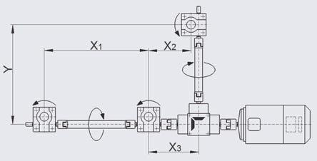
5 With an application sketch and the completed checklist it will enable us to submit our quotation more speedily. 4.2 Checklist Page 1 Parameters Company: Address: Contact: Departement: Date Phone.: Fax: Number of pages: 1 Axial capacity in kn, max. per gearbox kn per system kn in tension kn in compression kn load: static kn dynamic kn installation position: vertical horizontal idle impact load vibration 2 Lift / Travel mm 3 Lifting speed Type N = 1.5 m/min. Type L = m/min. (MSZ1 and bigger: slightly different speeds) Customer s requirements m/min (many variants are possible) 4a Operating time, operating cycle lifts per day lifts per hour hours per day: % operating time (ED) related to a 10 min period, for permanent operating see checklist page 2 (4b). 5 Gear type: S standing spindle R rotating spindle 6 Standard arrangement no. Dimension X1 X2 X3 Y see standard arrangements, checklist pages 5 and 6! 7 Accessories YES NO see checklist page 3 or 4! 8 Motor: AC motor brake motor manual operation spring pressure brake incremental encoder linear measuring system limit switches (S version) 9 Application objective / Function description Description: Operating conditions: Dry Humid Dusty Chips Ambient operating temperature: min. C max. C 10 Quantity: piece prototype first 11 Date: Offer: Delivery: 026 by ZIMM Austria 2006

6 4.2 Checklist Page 2 Operating Times Only required for extended operating times and high duty cycles. 4b Operating cycle for permanent operations / operation times Diagrams with times in seconds or minutes, resulting operating period in percent %, with calculation 8 16 or 24 hours operation / day Example: operation time sec. up 10 sec. still 5 sec. down 5 sec. still 5 sec. dwon 5 sec. 1 cycle 90 sec. still 60 sec. Idle time in sec. min. hours Formula for calculating the relative operating period ED: ED = te x ED in % (te+tp) ED= operating period te = operating time (in sec.) tp = idle time (in sec.) ED = 10 sec. + 5 sec. + 5 sec. (10 sec. + 5 sec. + 5 sec. + 5 sec. + 5 sec sec.) x = 22,2% per hour when operated 8hr/day by ZIMM Austria
 Execution: SN (standing spindle, normal speed) SL (standing spindle, low speed) Tension load [kn] statically Tension load [kn] dynamically Compression load [kn]")
![statically Compression load [kn] dynamically Pivot bearing head Forked head Rod end Fixing flange Bellows Spiral spring base line Handwheel Motor with brake Motor](/docs-images/90/103725015/images/7-1.jpg "without brake Coupling Rotary pulse encoder Mounting bars Motor flange Safety nut Hinged bearing plate Limit switch Spring pressure brake Protective cap Lubrication")
7 4.2 Checklist Page 3 Accessories S (also see overview chapter 3.3) Execution: SN (standing spindle, normal speed) SL (standing spindle, low speed) Tension load [kn] statically Tension load [kn] dynamically Compression load [kn] statically Compression load [kn] dynamically Pivot bearing head Forked head Rod end Fixing flange Bellows Spiral spring base line Handwheel Motor with brake Motor without brake Coupling Rotary pulse encoder Mounting bars Motor flange Safety nut Hinged bearing plate Limit switch Spring pressure brake Protective cap Lubrication strip Protection against rotation Escape Protection Protective tube Linear measuring system 028 by ZIMM Austria 2006
 Execution: RN (rotating spindle, normal speed) RL (rotating spindle, low speed) Tension load [kn] statically Tension load [kn] dynamically Compression load [kn]")
![statically Compression load [kn] dynamically Opposed bearing plate Tension Compression Bellows Flat spiral spring covering on top on bottom Duplex nut DM1 Flange nut FM](/docs-images/90/103725015/images/8-1.jpg "(trapezoid) Flange nut KGTF Selfaligning nut PM1 Greaseless nut FFDM Driving flange TRMFL Safety nut Wear control Mounting bars Coupling base line Handwheel Motor Motor with")
8 4.2 Checklist Page 4 Accessories R (also see overview chapter 3.4) Execution: RN (rotating spindle, normal speed) RL (rotating spindle, low speed) Tension load [kn] statically Tension load [kn] dynamically Compression load [kn] statically Compression load [kn] dynamically Opposed bearing plate Tension Compression Bellows Flat spiral spring covering on top on bottom Duplex nut DM1 Flange nut FM (trapezoid) Flange nut KGTF Selfaligning nut PM1 Greaseless nut FFDM Driving flange TRMFL Safety nut Wear control Mounting bars Coupling base line Handwheel Motor Motor with brake Rotary pulse encoder Motor flange Hinged bearing plate Spring pressure brake Protective cap by ZIMM Austria


9 4.2 Checklist Page 5 Standard Arrangements by ZIMM Austria 2006


10 4.2 Checklist Page 6 Standard Arrangements by ZIMM Austria


 theoretical")
 see pictograms above If the")
.")
11 4.3 Critical Buckling Force of the Lifting Screw f k = 1 f k = 0,25 f k = 2 f k = 4 Version S guided lifting motion with hinged plate Version S non guided lifting motion, gear firmly mounted Version S guided lifting motion, gear firmly mounted Version R for a small L 1 there applies: f k = 2 guided lifting motion Critical buckling force F k in kn There is a buckling risk especially with gearboxes with long, thin spindles in combination with compression load. With the following calculation you can find the max. allowed axial load acc. to Euler. Maximum allowed axial load F all = 0,8 x F k x f k free length L in mm F all F k f k maximum allowable axial load (kn) theoretical critical buckling force (kn) acc. to diagram correction value (considers kind of bearing support, respectively guidance of lifting load) see pictograms above If the max calculated load is lower than required a larger spindle diameter could be selected. The calculations must then be reworked. With the rotating screw version a larger diameter screw can be selected (from the next bigger gearbox size). Any increase in pitch/ lifting speed must be taken into account. The safety factors for the type of system specified must be used, as shown above, to calculate the max allowable axial load for the system. 032 by ZIMM Austria 2006
![4.4 Critical Whirling Speed of Spindle R Version theoretical spindle whirling speed nkr [min 1 ] with opposed bearing plate f kr = 1 without opposed bearing plate f kr = 0,5 Maximum allowable spindle](/docs-images/90/103725015/images/12-0.jpg "speed n all = 0,8 x n kr x f kr unsupported screw lengths [m] spindle speed = input speed igearbox For R version gearboxes (with rotating spindle) with long, thin spindles it is necessary to")

12 4.4 Critical Whirling Speed of Spindle R Version theoretical spindle whirling speed nkr [min 1 ] with opposed bearing plate f kr = 1 without opposed bearing plate f kr = 0,5 Maximum allowable spindle speed n all = 0,8 x n kr x f kr unsupported screw lengths [m] spindle speed = input speed igearbox For R version gearboxes (with rotating spindle) with long, thin spindles it is necessary to calculate the max. allowable spindle speed. Please take the theoretical critical speed nkr from the diagram. Also consider the additional lenghts for spindle covers, etc. when calculating the unsupported screw lengths. Together with the correction factor for the bearing layout the max. allowable spindle speed can be calculated. If the calculated max spindle speed is lower than that required, a larger spindle should be selected. The calculations must then be reworked. If a larger diameter spindle is used in the R version the potential for higher drive torque's must be considered. The safety factors for the type of system specified must be used, as shown above, to calculate the max allowable axial load for the system. by ZIMM Austria
![4.5 Determining the Drive Torque [M G ] of a Lifting Gear With the formula shown below it is possible to calculate the necessary drive torque.](/docs-images/90/103725015/images/13-0.jpg "In order to facilitate the calculation of the drive torque we have determined multiplication factors out of this formula and have stated them in the technical data for the single gearbox version.")
13 4.5 Determining the Drive Torque [M G ] of a Lifting Gear With the formula shown below it is possible to calculate the necessary drive torque. In order to facilitate the calculation of the drive torque we have determined multiplication factors out of this formula and have stated them in the technical data for the single gearbox version. Formula 1) : M G F η Gearbox η Spindle P i M L P M Required drive torque [Nm] of a lifting gear Lifting load (dynamic) [kn] Efficiency of the lifting gear (without spindle) Efficiency of the spindle Spindle pitch [mm] Transmission of the lifting gear Idling torque [Nm] Power of motor Example: MSZ25SN F = 12 kn (lifting load dynamic) η Gearbox = 0,87 η Spindle = 0,375 P = 6 i = 6 F [kn]. P [mm] Drive torque: M G = + M L [Nm] 2. π. η Gearbox. η Spindle. i M G = 12 kn. 6mm 2. π. 0,87. 0, ,36 Nm = 6,21 Nm Power of motor: P M[kW] = M G [Nm]. n [min 1 ] 95 P M = 6,21 Nm. 1 min 1 95 = 0,975 kw Safety factor (start torque) = calculated drive torque x 1.3 to 1.5 (for smaller systems use up to x 2).! Example: 0,975 kw. 1,4 = 1,365 kw motor 1,5 kw 1) For gearboxes with onepitch trapezoidal spindles it is also possible to multiply the factor which is stated on the corresponding gearbox page with the load. Tr Tr spindle η Spindle Efficiency single pitch P η lubricated 0,427 0,399 0,375 0,375 0,344 0,314 0,368 0,368 0,314 0,273 0,288 Tr Tr spindle η Spindle Efficiency double pitch P η lubricated 0,592 0,565 0,540 0,540 0,9 0,474 0,532 0,532 0,474 0,426 0,444 The efficiency of a trapezoid screw is substantially lower than that of ball screws due to friction. However, the trapezoid screw is technically more simple and more favourable. A safety device (e.g. a brake) is rarely required for trapezoid screws due to their selflocking MSZ N L MSZ N L 2 0,82 0,77 2 0,06 0,04 5 0,84 0,62 5 0,10 0, ,86 0, ,26 0, ,87 0, ,36 0,26 0,89 0,74 0,76 0,54 capability. With a ballscrew system an efficiency factor of η=0,9 can be used. It is essential to incorporate a break into a ballscrew system. Efficiency of gearboxes η Gearbox (without spindle) at n = 1. Idling torques M L of gearboxes [Nm] 0,85 0,65 1,68 1,02 1 0,84 0,67 1 1,90 1,20 2 0,86 0,72 2 2,64 1,94 3 0,87 0,70 3 3,24 2,20 0,84 0,62 3,96 2,84 6 0,85 0,65 6 5,60 3,40 With ball screws you basically can calculate with an efficiency factor of η=0, by ZIMM Austria 2006


14 4.6 Drive Torque for Gearboxes M R = M G x 2,25 Calculation The required drive torque of a lifting gear results from the sum of the moments of the individual lifting units. This is increased due to frictional losses of transmission components like couplings, connecting shafts, bevel gears, etc. To simplify the calculation, some factors for determining the drive torque in the most common applications are provided below. M R = M G x 2,1 M R = M G x 3,1 M R = M G x 3,35 M R = M G x 4,6 M R = M G x 6,8 M R = M G x 4,4 M R Total drive torque for the whole system M G Input torque of a single gearbox M A Starting torque max. 1,5 x M R M R = M G x 3,34 M R = M G x 3,27 Example (example from the left page, 12 kn per gearbox) M R = M G x 4,6 = 6,21 Nm x 4,6 = 28,57 Nm x safety factor 1,3 = 37,14Nm Attention: It is recommended to multiply the calculated value with a safety factor of 1.3 to 1.5 (for smaller systems factor up to 2). The indicated values are applicable in cases of uniform distribution of the lifting gear load onto all gears! by ZIMM Austria

15 4.7 Maximum Power / Moments F Load definitions F Lifting load tension and/or compression F S Side forces on the spindle v H Lifting speed of the spindle (or nut of the R version) F A Axial load of the input shaft F R Radial load of the input shaft M R Drive torque n R Drive speed F S V H lifting screw F R Please examine the information on the following pages before making your choice of the lifting gear suited for your application. Various influences and assumptions can only be estimated on the basis of information gained by experience. In case of doubt please contact our sales engineers. M R n R F A input shaft = worm shaft Side forces on the spindle Please refer to the ajoining table for the maximum permissable side force. Side forces should be supported by a guidance system whenever possible. The bronze bushings in the gearbox are a secondary support only and should not be relied upon as adequate guidance. The maximum side force at a given screw extension must not exceed that stated in the ajoining table. Attention: only statically allowed! maximum side force F S [N] (static) MSZ extended screw length in mm Max. drive torque The stated values of the table on the right should not be exceeded. If gearboxes are arranged in tandem or in larger arrangements the maximum drive torque may be higher. If there are more than 5 gearboxes in an arrangement please contact our sales engineers. Radial load on the input shaft The radial forces of the table on the right should not be exceeded if you use chain drives or belt drives. maximum drive torque M R [Nm] Type M R SN/RN M R SN/RN M R SL/RL M R SL/RL min SHZ 02 0,7 1,0 0,5 0,7 MSZ 5 6,4 10,4 2,6 4,3 MSZ 10 12,6 20,5 5,3 8,4 MSZ 25 21,7 34,2 7,8 12,5 MSZ 44,7 70,3 15,5 24,5 MSZ 72,0 114,9 17,0 27,8 maximum radial load acting on the input shaft F R [N] F R max. SHZ MSZ MSZ MSZ 25 0 MSZ 520 MSZ 800 MSZ MSZ 1 67,3 107,0 17,3 27,7 MSZ 2 118,4 185,1 23,5 36,6 Consider that the starting torque is factor 1.5 of the operation torque Limit values are mechanical consider thermical factors depending on operating time MSZ MSZ 3 187,0 295,7 40,2 63,9 MSZ 3 2 MSZ 204,3 325,6 42,8 71,2 MSZ 3780 MSZ 6 268,3 427,9 62,8 102,6 MSZ 7 415,0 663,0 83,0 132,0 MSZ by ZIMM Austria 2006
16 4.8 Calculating Spindle and Protective Tube Lengths The following tables will allow calculation of the required spindle and protective tube length for the screw jack system selected. Basic Depending on gearbox version and system components the spindle (and protective tube for S version) have to be extended. These lengths are important. For non standard layouts please provide a drawing or contact the technical department. Stroke + basic length (+ extensions for variants/system components) Example S: MSZ25SN, stroke: 2 mm bellow MSZ25FB0 (compression ZD=70mm) fixing flange BF (therefore bellow without retainer) protection against rotation VS limit switch ESSET Spindle length Tr: = 517 mm stroke basic length bellow limit switch spindle length (7027=43) + protection against rotation protective tube length SRO: = 376 stroke basic length limit switch protective tube length + protection against rotation Example R: MSZ25RN, stroke 2 mm spindle with pilot (opposed bearing plate GLP) bellow MSZ25FB0 (compression ZD=70mm) below and above duplex nut DM Spindle length Tr: = 560 mm stroke basic length bellow gearboxsided 2. bellow duplex nut spindle length (7010=60) (7015=55) Length calculation for connecting shafts can be found in chapter by ZIMM Austria
17 4.8 Length Calculation, Standing Version S Spindle spindle extension S version below gearbox (tube side) Tr basic length Tr basic length with safety nut Tr basic length AntiBacklash KGT basic length Escape prot./prot. against rot. (evtl. WMS) Limit switch3) (+evtl. linear measuring syst.) ES3) and hinged bearing plate (evtl. WMS) MSZ x x MSZ x x x x MSZ x x x x MSZ x x x x MSZ 325 x10 4 x MSZ x MSZ MSZ MSZ MSZ spindle extension S version above gearbox Bellows with bushing (GK / KGK)1) Bellows without bushing (BF / SLK)1) Bellows and KAR with FBR (GK / KGK)1) Bellows and KAR without FBR (BF / SLK)1) MSZ05 ZD 2 ZD 22 ZD +32 ZD +12 MSZ10 ZD +1 ZD 24 ZD +34 ZD +9 MSZ25 ZD +5 ZD 27 ZD +53 ZD +22 MSZ ZD +10 ZD 36 ZD +67 ZD +21 MSZ ZD +8 ZD 40 ZD +81 ZD +33 MSZ1 ZD +2 ZD 18 ZD +71 ZD +51 MSZ2 ZD +2 ZD 18 ZD +93 ZD +73 MSZ3 ZD +2 ZD 18 ZD +114 ZD +94 MSZ ZD +2 ZD 18 ZD +136 ZD +116 MSZ6 2) ZD +2 ZD 18 ZD +128 ZD +108 ZDMeasures: see capter Safety distances are already included in basic lengths! (Tr spindle: 10mm up to MSZ, 16mm from MSZ1, for KGT see chapter 9.1, dimension L3) 1) The value will be added or subtracted to the ZD dimension of the bellow the result will then be added to the spindle lenght. (e.g. ZD = 70 >> ZD22 = 48 mm >> spindle extension for bellow is 48 mm) 2) Bellow, bellow ring and bellow adapter are similar to MSZ 3) Limit switches ES are always in combination with protection against rotation VS (VS is in the extension included) Spindle extension for spiral spring covering SF: As the extension of the spiral spring covering differs depending on the attachment, this variant has to be calculated graphically. If necessary we would be pleased to generate this drawing. Abbreviations: AS Escape protection KAR Hinged bearing plate BF Fixing flange KGK Rod end ES Limit switch SLK Pivot bearing head FBR Bellows connecting ring WMS Linear measuring system GK Forked head ZD Compression 038 by ZIMM Austria 2006
 + VS ES 3) and hinged bearing plate KAR VS + Linear measuring system WMS MSZ5 48 16x05 60 16x10 80 15 69 91 31 MSZ10 25x05 60 25x10 80 25x25 1 25x 280 20 72 90 36 MSZ25 55 32x05 65 32x10 75")
18 4.8 Length Calculation, Standing Version S Protective Tube SRO protective tube extension S version Tr basic length 1) KGT basic length 1) Escape prot./prot. ag. rotat. AS/VS Limit switch ES3) (+ evtl. WMS) + VS ES 3) and hinged bearing plate KAR VS + Linear measuring system WMS MSZ x x MSZ10 25x x x x MSZ x x x x MSZ 64 40x x x x MSZ 75 x10 95 x MSZ x MSZ MSZ MSZ ) Basic length of protective tube without cap to achieve the whole protective tube length add another 5mm for the cap Attention: minimum stroke with limit switch ES: min.stroke with limit switch ES 3) 2) min.stroke with ES3) + lubric. strip 2) ) Is a lower stroke required as stated above, the limit swithces and the lubrication strips have to be mounted on two different sides (assembly position)! 3) Limit switches ES are always in combination with protection against rotation VS (VS is in the extension included) MSZ by ZIMM Austria
19 4.8 Length Calculation, Rotating Version R Spindle Spindle extension R version Tr basic length without machined end Tr basic length with machined end (= standard for opposed bearing plate GLP) Tr basic length larger diameter with machined end 1) KGT basic length without machined end 2) (including nut) KGT basic length larger diameter without machined end 2) (including nut) KGT basic lenth with machined end 2) (including nut) KGT basic length larger diameter without machined end 2) (including nut) Flange nut FM Duplex nut DM Selfaligning nut PM Greaseless nut FFDM DM + Safety nut SIFA PM + Safety nut SIFA 1. FB gearboxnut 5) 2. FB nutopposite bearing plate 5) KAR6) spindlesided and1. bellow 5) MSZ x x x x x x x x x x x x ZD 12 ZD 10 ZD +18 MSZ x x x x x x x x x x x x x x x x ZD 12 ZD 14 ZD +18 MSZ x x x x x x x x x x x x x x x x ZD 10 ZD 15 ZD +32 MSZ x x x x x x x x x x x x ZD 12 ZD 15 ZD +32 MSZ x x x x x x x x ZD 12 ZD 10 ZD +46 MSZ x x x x203) x204) x x x x203) x204) ZD 18 ZD 26 ZD +42 MSZ x x203) x204) 2 80x x203) x204) ZD 18 ZD 36 ZD +65 MSZ ZD 18 ZD 56 ZD +80 MSZ ZD 18 ZD 21 ZD + MSZ ZD 18 ZD 41 ZD +99 Safety distances are already included in basic lengths! (Tr spindle: 10mm up to MSZ, 16mm from MSZ1, for KGT see chapter 9.1, dimension L3) 1) When using a larger diameter spindle also select the system components of the next bigger gearbox. (MSZ10 with larger diameter spindle has spindle Trx6, system components of MSZ25 therefore also calculational spindle extension of gearbox size 25). 2) The basic length of KGT spindles includes the length of the KGT nut and the safety distance according to ZIMM catalogue (see chapter 9.2, size L3). 3) KGT nut with dynamic load rating 135kN and static load rating 322kN (80x204EP). 4) KGT nut with dynamic load 161,5kN and static load rating 398kN (80x205EP). 5) The value will be depending on the algebraic sign added or subtracted of the ZD (compression) dimension of the bellow the result will then be added to the spindle lenght. 6) KAR is the hinged bearing plate Spindle extension for spiral spring covering SF: As the extension of the spiral spring covering differs depending on the attachment, this variant has to be calculated graphically. If necessary we would be pleased to generate this drawing. 040 by ZIMM Austria 2006
20 4.9 Order Code MSZ Millennium Series ZIMM Size Housing material Version Ratio Version of thread SpindleØ / Pitch Number of gears, material Stroke MSZ H MSZ G Grey cast iron GG25 Heavy duty design (not specified = G) A Aluminium S Steel (MSZ 7) S Standing version R Rotating version N Normal e.g. i = 4:1 L Low e.g. i = 16:1 TR Trapezoidal spindle (not specified = Tr) > chapters 5 and 6 TR/SIFA Tr with safety nut SIFA > chapter 8 TR/AB Tr, AntiBacklash AB (only with S version) > chapter 10 KGT Ball screws > chapter 9 TR/SIFAVU with wear control TR/SIFADU with rotation control TR/SIFAVU/DU with rotaion + wear control TR KGT pitch (not specified = 1pitch) 2 * 2pitch I INOX (stainless) LH * leftthreaded *) available, but not from stock. Delivery time on request Stroke H + stroke in mm List of system components List of system components (order does not matter) > chapter 14 Size Material housing Version S or R Ratio N or L Version of thread Spindle diameter Spindle pitch Number of gears Stroke List of system components (order does not matter) Order expample: MSZ 10 G SN TR/SIFA H 0 FB390 VS BF by ZIMM Austria
Engineering Catalogue 2006
 Engineering Catalogue 06 The fascination of Building Block Systems The fascination with building block systems inspired creativity in many of us as children. The idea was conceived and successfully executed
Screw Jack Systems MSZ Alu series
 Screw Jack Systems MSZ Alu series EN www.zimm.eu Z series and GSZ series screw jacks The preferred range with full range Z series Z series screw jacks are the preferred range with the largest number of
System Overview - Screw Jacks S
 3. System Overview Screw Jacks S 3.3, Standing Spindle S Fixing flange BF Pivot bearing head SLK Motor Rod end KGK Bellow FB Spiral spring SF Rotary pulse encoder DIG Coupling KUZ Motor flange MF Lubrication
XII 1.1. Screw Jack Systems Electro Mechanical Positioning. Phone:
 XII 1.1 crew Jack ystems Electro Mechanical Positioning www.zimmscrewjacks.us Phone: 224-765-0663 POGAM, MAKET EGMENT Program benefits Precision acme and ball screws Translating and otating version Multiple
 www.motiontech.com.au Copyright SERVOMECH This catalogue contents are under publisher copyright and may not be reproduced unless permission is agreed. Every care has been taken to ensure the accuracy of
SGT screw jack. Product description. SGT 5 to SGT 1000 screw jack Both trapezoidal and ball screw versions.
 Product description SGT to SGT screw jack Both trapezoidal and ball screw versions ALBERT-SGT-screw jacks are electromechanical transmission components suitable for a wide spectrum of industrial machinery.
3. Screw jacks, rotating
 3. 061 by Nozag - 2015 3. The spindle has a fixed connection to the worm wheel and rotates with it. The nut therefore screws itself up and down. The innovative Nozag screw jack kit makes it possible to
Servomechkaramoottorit
 Solutions for power transmission Servomechkaramoottorit www.konaflex.fi INDEX 1 Servomech 1. THE PRODUCT 1.1 SERVOMECH Linear Actuators......................... Page 2 1.2 SERVOMECH Linear Actuators range............................
Linear Drive with Ball Screw Drive Series OSP-E..SB
 Linear Drive with Ball Screw Drive Series OSP-E..SB Contents Description Data Sheet No. Page Overview 1.30.001E 47-50 Technical Data 1.30.002E-1 to 5 51-55 Dimensions 1.30.002E-6, -7 56-57 Order instructions
DSH screw jack. Product description. DSH screw jack
 Product description DSH screw jack Conventional screw jack applications consist of one or more screw jacks. Usually they are driven by one electric motor and typically connected via drive shafts or couplings
Contents. Page. 1. Product description. 2. The AXC line of linear axes. 3. AXLT line of linear tables. AXC and AXS product overview...
 SNR Industry Contents Page 3 1. Product description AXC and AXS product overview... 6-8 Dynamic load ratings of the linear motion systems... 9 Compact modules... 10-11 Linear tables... 12 Telescopic axes...
Series BD Screw Jacks
 www.radicon.com Series BD Screw Jacks Technical Up to - 100Te / 5m/min Screw Jacks CBD-1.00GBD0111 SERIES BD PRODUCTS IN THE RANGE Serving an entire spectrum of mechanical drive applications from food,
SERVOMECH linear actuators are electromechanical cylinders able to transform a rotary movement into a linear motion.
 1.1 SERVOMECH LINEAR ACTUATORS SERVOMECH linear actuators are electromechanical cylinders able to transform a rotary movement into a linear motion. Developed and manufactured for industrial applications,
Ball screw drives KGT General technical data
 KGT General technical data Manufacturing process The thread profile is produced by cold rolling in the thread rolling method. Both screw and nut have a gothic thread profile. The load angle is 45. Linear
Acme Screw Jacks. Catalogue
 Acme Screw Jacks Catalogue SERVOMECH Screw Jacks MA Series Screw Jacks - high efficiency Max. duty cycle: travelling screw: 40 % over 10 min (30 % over 1 hour) travelling nut: 30 % over 10 min (20 % over
E-Series Screw Jacks. Metric Machine Screw Jack. Stainless Steel Machine Screw Jack. Metric Ball Screw Jack
 E-Series Screw Jacks Metric Machine Screw Jack Stainless Steel Machine Screw Jack Metric Ball Screw Jack E-Series 1 BEST ENGINEERED SOLUTION FOR PRECISION LINEAR ACTUATION, POWER TRANSMISSION & MECHANICAL
Profi le rail guides LLR
 Profi le rail guides LLR Content The SKF brand now stands for more than ever before, and means more to you as a valued customer. While SKF maintains its leadership as the hallmark of quality bearings throughout
Ball Rail Systems RE / The Drive & Control Company
 Ball Rail Systems RE 82 202/2002-12 The Drive & Control Company Rexroth Linear Motion Technology Ball Rail Systems Roller Rail Systems Standard Ball Rail Systems Super Ball Rail Systems Ball Rail Systems
Slotted nut NMG. Housing nut GWR. Bosch Rexroth AG. for economical constructions. a min. 0,3. M A = tightening torque of slotted nut.
 R310EN 3301 (2009.08) Precision Ball Screw Assemblies Bosch Rexroth AG 113 Slotted nut NMG for economical constructions B D d d1 b M A = tightening torque of slotted nut a min. 0,3 Polyamide insert Designation
Accessories for screw jacks type SGT
 Product description Accessories for Albert SGT screw jacks Both trapezoidal and ball screw version The comprehensive range of Albert accessories for screw jacks provides the designer with the means to
FTP Series HIGH FORCE ELECTRIC PRESS ACTUATOR
 FTP Series HIGH FORCE ELECTRIC PRESS ACTUATOR Ideal hydraulic press replacement Industry-leading power density Rugged and reliable Flexible and precise 952.500.6200 www.exlar.com 75 FTP Series High Force
The new performance class...
 The new performance class... 10/2017 EP(X)-II 30/40 EP(X)-II 30/40 twin tube actuator The latest generation of twin tube units Move-Tec EP(X)-II 30/40 Your application takes centre stage slow langsam A
V SWISS MADE LINEAR TECHNOLOGY
 Compact units Excerpt from main catalogue SWISS MADE LINEAR TECHNOLOGY V 11-15 Line Tech compact units Table of contents Product overview 106 107 Design fundamentals / Lubrication / Maintenance 108 Profile
C-SERIES S-SERIES. Metric Machine Screw Jacks EMA LINEAR ACTUATORS
 C-SERIES S-SERIES Metric Machine Screw Jacks EMA LINEAR ACTUATORS Power Jacks has a proud engineering heritage dating from the earliest years of the 20th Century. A heritage that is about excellence: about
Linear Drive with Toothed Belt and Integrated Guide with Recirculating Ball Bearing Guide with Roller Guide Series OSP-E..BHD
 Linear Drive with and Integrated Guide with Recirculating Ball Bearing Guide with Roller Guide Contents Description Page Overview 11-14 Version with Recirculating Ball Bearing Guide Technical Data 15-17
Helical Gear Motors BEGE Type G & M. Your drive, our (trans)mission. BEGE Power Transmission
mission. BEGE Power Transmission") Helical Gear Motors BEGE Type G & M BEGE Power Transmission Anton Philipsweg 30 2171 KX Sassenheim The Netherlands T: +31 252-220 220 E: bege@bege.nl W: www.bege.nl Your drive, our (trans)mission General
Helical Gear Motors BEGE Type G & M BEGE Power Transmission Anton Philipsweg 30 2171 KX Sassenheim The Netherlands T: +31 252-220 220 E: bege@bege.nl W: www.bege.nl Your drive, our (trans)mission General
mechanics LES functional overview LES 4 LES 6 LES 5
 LES functional overview LES 4 with spindle drive Overview 2-54 2-56 LES 6 2-58 with spindle drive LES 5 2-60 with spindle drive Calculations 2-62 Combination examples Motor modules Clutch housing Motor
C-SERIES S-SERIES. Metric Machine Screw Jacks
 -SERIES S-SERIES Metric Machine Screw Jacks Power Jacks are a manufacturer focused on providing customers with the best engineered solution for precision linear actuation, power transmission and mechanical
Linear Motion Technology Handbook. The Drive & Control Company
 Linear Motion Technology Handbook The Drive & Control Company 1-2 Bosch Rexroth AG Linear Motion Technology Handbook R310EN 2017 (2006.07) Linear Motion and Assembly Technologies www.boschrexroth.com/brl
Linear Actuator with Toothed Belt Series OSP-E..B
 Linear Actuator with Toothed Belt Series OSP-E..B Contents Description Data Sheet No. Page Overview 1.20.001E 21-24 Technical Data 1.20.002E-1 to 5 25-29 Dimensions 1.20.002E-6 30 Order Instructions 1.20.002E-7
V SWISS MADE LINEAR TECHNOLOGY
 Excerpt from main catalogue inear modules V 11-15 SWISS MDE INER TECHNOOGY ine Tech inear modules Table of contents Product overview 6 7 Design fundamentals / ubrication / Maintenance 8 Profile cross-sections
Linear Actuator with Ball Screw Series OSP-E..S. Contents Description Overview Technical Data Dimensions 89
 Linear Actuator with Ball Screw Series OSP-E..S Contents Description Page Overview 79-82 Technical Data 83-88 Dimensions 89 79 The System Concept ELECTRIC LINEAR ACTUATOR FOR HIGH ACCURACY APPLICATIONS
ROTARY TABLES SERIE TC TECHNOLOGY THAT INSPIRES
 ROTARY TABLES SERIE TC TECHNOLOGY THAT INSPIRES TC FIXED-STATION ROTARY INDEXING TABLES TC ROTARY INDEXING TABLE TC ROTARY INDEXING TABLE: RELIABILITY FOR A LIFETIME EXTENDED WARRANTY Using our rotary
4 Project planning for drives
 Additional publications Project planning for drives. Additional publications For more detailed information about the project planning for drives, refer to the website of SEW-EURODRIVE where you can download
Electric cylinders CASM
 Electric cylinders CASM 32-4-63 Contents Product description 4 Motors and gearboxes 6 Manuals 1 3D models 1 Linear unit 3 12 Linear unit 4 14 Linear unit 63 16 linear unit 18 Actuator 32 2 Actuator 4 32
Screw jacks MA Series
 Screw jacks MA Series Screw jacks MA Series with travelling screw (Mod.A) STRUCTURAL ELEMENTS 1 10 11 8 7 6 1 3 13 4 9 14 8 11 10 5 6 7 1 - acme screw in steel C 43 (UNI 7847), whirled thread - worm shaft
Main Catalogue. EichenbergerGewinde. 100 % Swiss made
 EichenbergerGewinde 100 % Swiss made Main Catalogue Carry ball screws Carry Speed-line high-helix ball screws Speedy high-helix lead screws Rondo round thread lead screws The choice is yours Thread rolling
Miniature Ball Rail Systems
 R310EN 2210 (2004.06) The Drive & Control Company 2 Bosch Rexroth AG Linear Motion and Assembly Technologies Miniature-BRS R310EN 2210 (2004.06) Linear Motion Systems Ball Rail System Standard Ball Rail
Industry. SNR Linear Motion : Ball screws
 Industry SNR Linear Motion : Ball screws SNR A global manufacturer of bearings. For almost a century, SNR has designed, developed and manufactured bearings to meet the most demanding of applications. In
Lenze. Drives with worm gearboxes 52.
 6 887 Lenze Drives with worm gearboxes 5. Lenze Drive Systems GmbH, Postfach 0 5, D-76 Hameln, Site: Groß Berkel, Hans-Lenze-Straße, D-855 Aerzen, Phone ++9 (0) 55 8-0, Telefax ++9 (0) 55 8- E-Mail: Lenze@Lenze.de
DRIVE-TECHNOLOGY INKOMA - GROUP. Accessories for screw jacks type SGT. Maschinenfabrik ALBERT GmbH Technologiepark 2 A Gampern - Austria
 DRIVETECHNOLOGY ALBERTINKOMA GROUP Accessories for screw jacks type SGT Maschinenfabrik ALBERT GmbH Technologiepark 2 A 81 Gampern Austria phone: +3/(0)76823 fax: +3/(0)7682399 email: office@albert.at
Linear Drive with Toothed Belt Series OSP-E..B. Contents Description Overview Technical Data Dimensions Order Instructions 46
 Linear Drive with Toothed Belt Contents Description Page Overview 35-38 Technical Data 39-43 Dimensions 44-45 Order Instructions 46 35 The System Concept ELECTRIC LINEAR DRIVE FOR POINT-TO-POINT APPLICATIONS
...components in motion. Miniature Linear Guideways
 ...components in motion Miniature Linear Introduction Miniature linear guideway systems are widely used throughout industry for precise, compact applications. Precise and Stainless The gothic arch shape
1. Product overview Basic-Line-Module AXN Product description Basic-Line-Module AXN 4-5. Guide system Roller guide 6 Drive system Gear belt 7
 Directory Page 1. Product overview Basic-Line-Module AXN 3 2. Product description Basic-Line-Module AXN 4-5 Guide system Roller guide 6 Drive system Gear belt 7 3. Basic-Line-Modul AXN 45-Z 8-9 AXN 65-Z
TOOLFLEX Operating-/Assembly Instructions
 D-807 Rheine heet: 5810 EN 1 of 19 Backlash-free, torsionally stiff and maintenance-free coupling is a backlash-free, torsionally stiff and maintenance-free metal bellow-type coupling designed to be used
Benzlers Screw Jacks. Benzlers Screw Jacks CBD-2.00GB0613
 enzlers Screw Jacks enzlers Screw Jacks D-2.00G0613 ATEX ompliance Assured Total compliance with the ATEX Directive safeguarding the use of industrial equipment in potentially explosive atmospheres is
Courtesy of CMA/Flodyne/Hydradyne Motion Control Hydraulic Pneumatic Electrical Mechanical (800)
") 01_1 Miniature st Headline_36 Ball Rail pt/14.4 Systems mm second line 2 Linear Motion and Assembly Technologies Miniature Ball Rail Systems Ball Rail Systems Roller Rail Systems Linear Bushings and Shafts
01_1 Miniature st Headline_36 Ball Rail pt/14.4 Systems mm second line 2 Linear Motion and Assembly Technologies Miniature Ball Rail Systems Ball Rail Systems Roller Rail Systems Linear Bushings and Shafts
BEARINGS The lower bearing assemble is constructed to allow continuous operation when fully submerged in wastewater.
 GENERAL SPECIFICATION INTENT The equipment to be supplied by manufacturer includes the screw pumps, support for the drive unit, profile plates, motors, gearboxes, couplings, guards, upper and lower bearing
Linear Actuator with Toothed Belt and Integrated Roller Guide Series OSP-E..BHD
 inear Actuator with Toothed Belt and Integrated Roller Guide Series OSP-E..BHD Contents Description Data Sheet No. Page Overview 1.15.001E 11-14 Technical Data 1.15.002E-1 to 3 15-17 Dimensions 1.15.002E-4
Linear actuators ILA Series
 Linear Actuator ILA Series without input drive, with flange and input shaft Linear Actuator ILA Series with input drive - with 2 bevel gearmotors - with single bevel gearmotor - with helical coaxial or
Linear Actuator with Ball Screw Series OSP-E..S. Contents Description Overview Technical Data Dimensions 79
 Linear Actuator with Ball Screw Series OSP-E..S Contents Description Page Overview 71-74 Technical Data 75-78 Dimensions 79 71 The System Concept ELECTRIC LINEAR ACTUATOR FOR HIGH ACCURACY APPLICATIONS
 heet: 1 of 22 Backlash-free, torsionally stiff and maintenance-free coupling Type with setscrew Type with clamping hubs Type KN (Taper hubs) Type M with setscrew Type M with clamping hubs Type PI 11-3379-883
Profile rail guides LLT
 Profile rail guides LLT Contents The SKF brand now stands for more than ever before, and means more to you as a valued customer. While SKF maintains its leadership as the hallmark of quality bearings throughout
Screw Jacks. Lifting >> Tilting >> Lowering >> Feeding sm. MARYLANDMETRICS phones: (800) (410) faxes: (800) (410)
 (410) faxes: (800) (410)") Cubic Screw Jack Family MULI, JUMBO MULI, JUMBO Lifting >> Tilting >> Lowering >> Feeding sm Cubic Screw Jacks RHINO MARYLAND METRICS offers: Screw Jacks Superior performance. Superior design. MARYLANDMETRICS
Cubic Screw Jack Family MULI, JUMBO MULI, JUMBO Lifting >> Tilting >> Lowering >> Feeding sm Cubic Screw Jacks RHINO MARYLAND METRICS offers: Screw Jacks Superior performance. Superior design. MARYLANDMETRICS
using Class 2-C (Centralizing) tolerances. Jack lift shaft lead tolerance is approximately 0.004" per foot.
 tolerances. Jack lift shaft lead tolerance is approximately 0.004 per foot.") WORM GEAR JACK MODELS WORM GEAR ACTIONJAC JACKS Jack systems are ruggedly designed and produced in standard models with load handling capacities from 1/4 ton to 100 tons. They may be used individually
WORM GEAR JACK MODELS WORM GEAR ACTIONJAC JACKS Jack systems are ruggedly designed and produced in standard models with load handling capacities from 1/4 ton to 100 tons. They may be used individually
Studying the Positioning Accuracy
 Ball Screw Studying the Positioning Accuracy Causes of Error in the Positioning Accuracy Point of Selection Studying the Positioning Accuracy The causes of error in the positioning accuracy include the
Main Catalogue. EichenbergerGewinde. 100 % Swiss made
 EichenbergerGewinde 100 % Swiss made Main Catalogue Carry ball screws Carry Speed-line high-helix ball screws Speedy high-helix lead screws Rondo round thread lead screws The choice is yours Thread rolling
ACME SCREW LINEAR ACTUATOR. Current [A] PERFORMANCES with AC 3-phase 50 Hz 230/400 V or 1-phase 50 Hz 230 V motor
![ACME SCREW LINEAR ACTUATOR. Current [A] PERFORMANCES with AC 3-phase 50 Hz 230/400 V or 1-phase 50 Hz 230 V motor](/thumbs/89/99042793.jpg "ACME SCREW LINEAR ACTUATOR. Current [A] PERFORMANCES with AC 3-phase 50 Hz 230/400 V or 1-phase 50 Hz 230 V motor") ACME SCREW LINEAR ACTUATOR CLA 28 OVERALL DIMENSIONS La = Lc + Stroke Stroke Lc T Standard head with threaded hollow bore BA Motor cable length 0.3 m Bronze bushes depth 17 Lc [mm] T [mm] Length [mm] +
ACME SCREW LINEAR ACTUATOR CLA 28 OVERALL DIMENSIONS La = Lc + Stroke Stroke Lc T Standard head with threaded hollow bore BA Motor cable length 0.3 m Bronze bushes depth 17 Lc [mm] T [mm] Length [mm] +
R310EN 2302 ( ) The Drive & Control Company
 The Drive & Control Company") R31EN 232 (26.4) The Drive & Control Company Bosch Rexroth AG Linear Motion and Assembly Technologies Ball Rail Systems Linear Bushings and Shafts Ball Screw Drives Linear Motion Systems Basic Mechanical
R31EN 232 (26.4) The Drive & Control Company Bosch Rexroth AG Linear Motion and Assembly Technologies Ball Rail Systems Linear Bushings and Shafts Ball Screw Drives Linear Motion Systems Basic Mechanical
Are you looking for specific bearing units in all kinds of different types from one single supplier? We make it easy for you to find the right one.
 Are you looking for specific bearing units in all kinds of different types from one single supplier? We make it easy for you to find the right one. Plain Bearing Units Geometric Shape Range: Bushings,
Z-50-S Standing Spindle 50 kn
 Z-50-S Standng Spndle 50 kn Safety Safety nut nut New: Spndle lubrcaton durng operaton Ths page Secton.29 Secton.27 M12/16 deep 52J7/ deep M10/15 deep SRO Length M12/16 deep Fttng heght Y Overall heght
R310EN 2211 ( ) The Drive & Control Company
 The Drive & Control Company") eline Ball Rail Systems R310EN 2211 (2006.04) The Drive & Control Company Bosch Rexroth AG Linear Motion and Assembly Technologies Ball Rail Systems Roller Rail Systems Linear Bushings and Shafts Ball
eline Ball Rail Systems R310EN 2211 (2006.04) The Drive & Control Company Bosch Rexroth AG Linear Motion and Assembly Technologies Ball Rail Systems Roller Rail Systems Linear Bushings and Shafts Ball
MKD04 COMPACT MOTORS
 MKD04 COMPACT MOTORS T E C H N I C A L C A T A L O G Compact motors MKD04 POCLAIN HYDRAULICS Methodology : This document is intended for manufacturers of machines that incorporate Poclain Hydraulics products.
Screwjack options. When stainless steel screws are specified, we can supply the flange end and rod end in stainless if requested.
 Raised cover CA Available for MA screwjacks, the steel raised covers with toleranced dimensions act as a centring register, also allow the fitting of bronze guide bushes, protective tubes and bellows.
JTW-SERIES MACHINE SCREW JACK
 J A C TO N I N D U S T RY C O., LT D L I F T I N G S Y S T E M S S O L U T I O N S TEL: 86-769-81585810, 81585852 SKYPE: jactonjack EMAIL: sales@screwactuator.com WEB: www.screwactuator.com SERIES MACHINE
Main Catalogue. EichenbergerGewinde. 100 % Swiss made
 EichenbergerGewinde 100 % Swiss made Main Catalogue Carry ball screws Carry Speed-line high-helix ball screws Rondo round thread lead screws Summary description ball screws Due to their premium quality
Technical description... 1 Limit switches Mini Dimensions... 8 Power tables Spare part lists... 12
 Content Technical description... 1 Limit switches... 5 Mini 0... 7 Dimensions... 8 Power tables... 11 Spare part lists... 12 Mini 01... 15 Dimensions... 16 Power tables... 18 Spare part lists... 19 Mini
Vertical Linear Drive with Toothed Belt and Integrated Recirculating Ball Bearing Guide Series OSP-E..BV
 Vertical Linear Drive with Toothed Belt and Integrated Recirculating Ball Bearing Guide Series OSP-E..BV Contents Description Page Overview 25-28 Technical Data 29-33 Dimensions 34 Order Instructions 35
C-SERIES S-SERIES EMA LINEAR ACTUATORS. Metric Machine Screw Jacks.
 C-SERIES S-SERIES Metric Machine Screw Jacks EMA LINEAR ACTUATORS 0i 02 Power Jacks has a proud engineering heritage dating from the earliest years of the 20th Century. A heritage that is about excellence:
PRECISION BELLOWS COUPLINGS
 PRECISION BELLOWS COUPLINGS Bellows couplings are used where precise rotation, high speeds, and dynamic motion must be transmitted. They exhibit zero backlash and a high level of torsional stiffness, offering
Vertical Linear Drive with Toothed Belt and Integrated Recirculating Ball Bearing Guide Series OSP-E..BV
 Vertical Linear Drive with and Integrated Recirculating Ball Bearing Guide Series OSP-E..BV Contents Description Page Overview 25-28 Technical Data 29-31 Dimensions 32-33 25 Parker Hannifin Corporation
Worm Gear Screw Jacks Muli, Jumbo
 Worm Gear Screw Jacks Muli, Jumbo Worm Gear Screw Jacks Contents Introduction worm gear screw jacks........................................ 4 7 Systematic gear technology...........................................................
The world is movement
 The world is movement 01 SCREW JACKS THERE IS A DRIVING FORCE MORE POWERFUL THAN STEAM, ELECTRICITY AND ATOMIC ENERGY: THE WILL. ALBERT EINSTEIN Physicist Niasa actuators in the Tonopah thermo-solar plant,
4 Project Planning for Gear Units
 Efficiency of gear units Project Planning for Gear Units.1 Efficiency of gear units The efficiency of gear units is mainly determined by the gearing and bearing friction. Keep in mind that the starting
Vertical Linear Drive with Toothed Belt and Integrated Recirculating Ball Bearing Guide Series OSP-E..BV
 Vertical Linear Drive with and Integrated Recirculating Ball Bearing Guide Series OSP-E..BV Overview...25-28 Technical Data...29-31 Dimensions...32-33 25 Features TOOTHED BELT DRIVE FOR VERTICAL MOVEMENTS
Description Symbol Definition or explanation Rated torque T KN Torque that can continuously be transmitted over the entire permissible speed range
 Coupling selection Normally the is selected according to the nominal torque ( ) shown in the list of technical data, like all other coupling systems. In all cases the torque ( ) must exceed the maximum
Main Catalogue. EichenbergerGewinde
 EichenbergerGewinde Main Catalogue Carry ball screws Carry Speed-line high-helix ball screws Speedy high-helix lead screws Rondo round thread lead screws The choice is yours Thread rolling is the core
Power Jacks have taken time, engineering excellence and the best people to produce the ultra compact Neeter Drive gearbox.
 202 www.powerjacks.com Power Jacks have taken time, engineering excellence and the best people to produce the ultra compact Neeter Drive gearbox. Our expertise has been built on a history of engineering
E / HYDAC KineSys Electric cylinders (HEZ)
") E 10.146.1.1/02.15 HYDAC KineSys Electric cylinders (HEZ) NOTE The information in this brochure relates to the operating conditions and applications described. For applications or operating conditions
E 10.146.1.1/02.15 HYDAC KineSys Electric cylinders (HEZ) NOTE The information in this brochure relates to the operating conditions and applications described. For applications or operating conditions
Technical description... 1 Limit switch versions MR 6 Power tables... 6 Dimensions... 7 Spare part lists... 8
 Index Technical description... 1 Limit switch versions... 3 MR 6 Power tables... 6 Dimensions... 7 Spare part lists... 8 MS 12 Power tables... 10 Dimensions... 11 Spare part lists... 13 MR 30 Power tables...
Sizes 32, 40, 50 and 63
 > Series 6E electromechanical cylinders C_Electrics > 207 Series 6E electromechanical cylinders Sizes 32, 40, 50 and 63 The Series 6E cylinders are mechanical linear actuators with rod, in which the rotary
SPIRACON. ROLLER SCREWS SPIRACON PRODUCT CATALOGUE
 SPIRACON ROLLER SCREWS PRODUCT CATALOGUE SPIRACON www.powerjacks.com TOTAL CAPABILITY IN ACTUATION Power Jacks is a world leader and pace-setter in the field of mechanical linear actuation and power transmission,
drylin TR Lead Screw Drives
 drylin TR drylin TR Lead Screw Drives Maintenance free, dry running, low noise Insensitivity to dirt Corrosion-free Trapezoidal and high helix thread Excellent emergency running properties Anti-Backlash
EMC-HD. C 01_2 Subheadline_15pt/7.2mm
 C Electromechanical 01_1 Headline_36pt/14.4mm Cylinder EMC-HD C 01_2 Subheadline_15pt/7.2mm 2 Elektromechanischer Zylinder EMC-HD Short product name Example: EMC 085 HD 1 System = ElectroMechanical Cylinder
Precision Lead Screws
 Precision Lead Screws ov-precision_lead_screws_divider - Updated - 18-09-2017 163 Precision Lead Screws Technical Information Precision lead screws ov-precision_lead_screws_technical_info - Updated - 18-09-2017
RE / STAR Tolerance Rings STAR Ball Knobs, Knob and Lever Type Handles
 RE 2 970/.99 STAR Tolerance Rings STAR Ball Knobs, Knob and Lever Type Handles STAR Tolerance Rings Product Overview Tolerance rings are made of hard, embossed spring steel strip and belong to the class
Stromag Dessau. safety in motion PRODUCT CATALOGUE. NFF4F-LS Brake. for Slow-Running High Torque Drivelines, in harsh environment
 Stromag Dessau safety in motion PRODUCT CATALOGUE NFF4F-LS Brake for Slow-Running High Torque Drivelines, in harsh environment ENGINEERING THAT MOVES THE WORLD Applications Holding brake variations with
PRS Series Planetary Roller Screws. A Superior Alternative to Hydraulic or Pneumatic Motion Providing 15 times the Life of a Ballscrew
 PRS Series Planetary Roller Screws A Superior Alternative to Hydraulic or Pneumatic Motion Providing 15 times the Life of a Ballscrew Exlar Roller Screw Advantage Roller Screw Overview A roller screw is
to move Electric Roller Screw Servo Actuators for Spot Welding
 Engineered to move Electric Roller Screw Servo Actuators for Spot Welding INDUSTRIAL ROLLER SCREW SERVO ACTUATORS Strong, Consistent Force for Maximum Productivity and Weld Quality Diakont delivers the
Servomech 1.4 BALL SCREW LINEAR ACTUATORS Series BSA
 1.4 BALL SCREW LINEAR ACTUATORS Series BSA Technical features table SIZE FEATURES BSA 10 BSA 20 BSA 25 BSA 30 BSA 40 Rod diameter [mm] 25 25 30 35 40 Protective tube diameter [mm] 36 36 45 55 60 Motor
Courtesy of CMA/Flodyne/Hydradyne Motion Control Hydraulic Pneumatic Electrical Mechanical (800)
") P01 LinMot P is a family of linear direct drives for highly dynamic motions. The motor is made up of just two parts: the slider and the stator. The two parts are not connected by brushes or cables. The
P01 LinMot P is a family of linear direct drives for highly dynamic motions. The motor is made up of just two parts: the slider and the stator. The two parts are not connected by brushes or cables. The
BoWex FLE-PA. BoWex FLE-PAC. KTR-N Sheet: Edition: EN 1 of BoWex FLE-PA / FLE-PAC Operating/Assembly instructions
 1 of 17 is a torsionally rigid flange coupling. It is able to compensate for shaft misalignment, for example caused by manufacturing inaccuracies, thermal expansion, etc. BoWex FLE-PA BoWex FLE-PAC Drawn:
ISOMOVE. Mechanical actuators ISO 6431
 ISOMOVE Mechanical actuators ISO 6431 ISOMOVE INDEX 2 Introduction 4 Mounting information and advices 6 10 40 14 20 63 25 80 29 33 Overall dimensions INTRODUCTION GENERAL FEATURES The ISOMOVE actuators
High Precision Bearings for Combined Loads
 High Precision Bearings for Combined Loads Axial/radial bearings Axial angular contact ball bearings Axial/radial bearings with angular measuring system added competence for your success With their forward-looking
Application Information
 Moog Components Group manufactures a comprehensive line of brush-type and brushless motors, as well as brushless controllers. The purpose of this document is to provide a guide for the selection and application
Servomech 1.4 BALL SCREW LINEAR ACTUATORS Series BSA
 1.4 BALL SCREW LINEAR ACTUATORS Series BSA Technical features table SIZE FEATURES BSA 10 BSA 20 BSA 25 BSA 30 BSA 40 Rod diameter [mm] 25 25 30 35 40 Protective tube diameter [mm] 36 36 45 55 60 Motor
Servomech 1.4 BALL SCREW LINEAR ACTUATORS Series BSA
 1.4 BALL SCREW LINEAR ACTUATORS Series BSA Technical features table SIZE FEATURES BSA 10 BSA 20 BSA 25 BSA 30 BSA 40 Rod diameter [mm] 25 25 30 35 40 Protective tube diameter [mm] 36 36 45 55 60 Motor
WIESEL SPEEDLine WHZ80 with roller guideway and AT toothed belt
 WIESEL WHZ80 with roller guideway and AT toothed belt All figures shown in millimeters. Note: Mounted wipers on request. The use of a long power bridge increases the total length. Technical data Linear
Standard Cylinder Series SZ 100
 Standard Cylinder Series SZ 100 Maximum operating pressure up to 100 bar Choice of 13 different piston sizes between 12 und 200mm and 23 different attachments Rugged yet compact design with good guiding
LINEAR ACTUATORS WITH INTEGRATED REDUCTION AND CUBIC GEARBOX
 03 LINEAR ACTUATORS WITH INTEGRATED REDUCTION AND CUBIC GEARBOX FM Series: Steel tube AM Series: Aluminum tube Page: 115 Page: 116 SUSTAINABILITY IS INDUSTRIALISED ECOLOGY. DAVID GARCÍA HOME-THERME NIASA