Engineering Catalogue 2006
|
|
|
- Maria Haynes
- 5 years ago
- Views:
Transcription

1 Engineering Catalogue 06

2 The fascination of Building Block Systems The fascination with building block systems inspired creativity in many of us as children. The idea was conceived and successfully executed by many well known toy manufacturers in the past. These systems are still extremely popular today. This concept has gained tremendous interest for machinery design and development, especially in the application of mechanical components. Standard products with a wide variety of available features offer the design engineer many more options. To advance this trend, the ZIMM Building Block System, orginally designed with the engineer's needs in mind, has been further improved and expanded to provide even more value and allow more creativity in the machinery design process. Be inspired by the new ZIMM Building Block System! ZIMM Maschinenelemente GmbH + Co Millennium Park Lustenau/Austria Tel 0043(0)5577/80 Fax 0043(0)5577/ sales@zimm.at Internet:

3 by ZIMM Austria


4 Our History ZIMM Maschinenelemente GmbH + Co We have been involved in drive technology for over years. We have carried out a wide range of projects during this time and strengthened our competence. We started out as toothed gear element suppliers for machine manufacturers we delivered standard parts from our catalogue as well as special parts to meet customers demands. Our emphasis has moved to electromechanical options for linear movement. Our ZIMM modular system for spindle lifting gear units provides a wide product range to meet and satisfy customer demands and wishes. The application range is so wide that we will just mention some classical applications such as theatre and stage technology, height adjustment for tables, platforms, conveyor belts, shaft and roller adjustment or exact load positioning in assembly and handling technology. Our modular system lets you choose from many standardized components with the advantage of short delivery times. Many additional component and solution options complement these standard components, so that we can deliver "from one source", partially or fully assembled. Gunther and Jürgen Zimmermann CEO 002 by ZIMM Austria 06


5 ZIMM sales team Our Engineering Catalogue is available in: > German > English > French > Italian > Spanish CADFiles To support your construction tasks, our components are available as CAD files on our CDROM or you download the latest data from our homepage We are certified according to EN ISO 9001, , Reg. No. 953/0 by ZIMM Austria


6 Page Chapter Con ZIMM Screw Jack Building Block System Content Practical Application of Screw Jacks System Overview Selection Support 4. Selection Calculation Checklists Screw Jacks Heavy Duty MSZ kn 5,,,, 0 6. kn 1, 2, 3, 0, 6, 7 7. Screw Jacks MSZ Alu with aluminium housings kn 5,, Screw Jacks Heavy Duty MSZ with safety nut with rotation control and fail safe wear control Screw Jacks Heavy Duty MSZ with integrated ball screws KGT optional pitches. Screw Jacks Heavy Duty MSZ Anti Backlash AB, with adjustable thread play Screw Jack Actuators hinged bearing plate design support tube design 004 by ZIMM Austria 06


7 tent Page Chapter Bevel gearboxes with straight bevel gears KLM and KGZ, with spiral bevel gears KSZ Heavy duty design KST 13. Worm Gears MSG 089. System Components for Screw Jacks MSZ Miniature Screw Jack Building Block System SHZ 02. Mounting, Operation and Maintenance Instruction for MSZ Spare Parts 17. General Terms and Conditions of Sale and Delivery, Sales Partners Worldwide 18. Copyright by ZIMM 04 Location + Direction by ZIMM Austria


8 2. Applications Application Examples of Screw Jacks Destacking unit Destacking unit for plates Mobile scissor table for pallet transfer with a hand lift 006 by ZIMM Austria 06


9 2. Applications Application Examples of Screw Jacks Threepoint system of a lapping and polishing apparatus, diameter mm. Compensation is made for different component sizes by the screw jack. Parabolic Antenna Ø = 3,3 m Both axes azimuth + elevation each kn. Setting range per movement 0,02 0,05 mm. These installations are outside along coastal regions. Adjustment of the steel shuttering for concrete beams 8 screw jacks of kn each. by ZIMM Austria


10 2. Applications Application Examples of Screw Jacks Combination of several scissor tables for exact positioning of a platform Stage adjustment Mobile lifting platform for heavy vehicles 008 by ZIMM Austria 06


11 2. Applications Application Examples of Screw Jacks Alignment of steel profiles Centering mechanism with right and left threaded spindles Motor gripper for steel profile Adjustment of a roller system in the textile industry by ZIMM Austria


12 2. Applications Application Examples of Screw Jacks Compact press Position drive for feed slide in a grain shaft Height adjustment at bottle monitoring systems Angle adjustment of a plate saw screw jack with linear measuring system 0 by ZIMM Austria 06


13 2. Applications Application Examples of Screw Jacks Scissor table Mobile lifting platform Conveyor adjustment by ZIMM Austria


14 2. Applications Application Examples of Screw Jacks The lower and upper part of the linear freezedryer system is opened electromechanically with screw jacks for cleaning. Wide belt grinding machine precise adjustable stop with 4 screw jacks Opening and closing of a sealed pressure tank 0 by ZIMM Austria 06


15 2. Applications Application Examples of Screw Jacks Turning over of foil coils (horizontal + vertical take up) Permanent discharge level regulation by means of lifting gears in a mobile container for panel production. by ZIMM Austria


16 Innovation in Design 0 by ZIMM Austria 06


17 Advanced Screw Jack Building Block System by ZIMM Austria 06 0


18 3. System Overview Screw Jacks 3.1 Standard Version with Standing Spindle S Standing spindle S The worm wheel has an internal thread and transforms rotary motion into linear movement as long as the spindle is prevented from rotating either by connection to the customer's fabrication or by incorporating the protection against rotation VS option chapter.1) Cast iron housing version S Aluminium housing version S Safety nut SIFA for fail safe wear control Ball Screws with optional pitches version KGT Anti Backlash AB with adjustable thread play 0 by ZIMM Austria 06


19 3. System Overview Screw Jacks 3.2 Standard Version with Rotating Spindle R Rotating spindle R A flange nut moves up and down on a rotating screw. Cast iron housing version R Aluminium housing version R Safety nut SIFA for fail safe wear control Ball Screws with optional pitches version KGT by ZIMM Austria
20 3. System Overview Screw Jacks S 3.3 System Components, Standing Spindle S Fixing flange BF Pivot bearing head SLK Motor Rod end KGK Bellow FB Spiral spring SF Rotary pulse encoder DIG Coupling KUZ Motor flange MF Lubrication strip SL Locking nut Forked head GK Tr left handed thread Tr INOX (stainless) Tr double pitch KGT Ball Screw Tr Standard Handwheel HR Spring brake FDB Assembly group limit switches ESSET Fixing strips BFL Protective cap SK Connecting Shaft VWZ Hinged bearing plate KAR Protection against rotation VS Escape protection AS Linear measuring system WMS 018 by ZIMM Austria 06
21 3. System Overview Screw Jacks R 3.4 System Components, Rotating Spindle R Opposed bearing plate GLP KGT Driving flange KGMFL KGT Pivot adapter KGKAR Spiral spring SF Tr Driving flange TRMFL KGTF KGT Flange nut Motor Bellow FB Duplex nut DM Flange nut FM Greaseless nut FFDM Selfaligning nut PM Safety nut SIFA Rotary pulse encoder DIG Coupling KUZ Spindle types: Standard Tr INOX (stainless) Double pitch Left handed thread Larger diameter spindle Ball screw KGT Motor flange MF Handwheel HR Spring brake FDB Protective cap SK Connecting shaft VWZ Fixing strips BFL Hinged bearing plate KAR by ZIMM Austria

22 3. System Overview Screw Jacks 3.5 Complete Solutions ZIMM Screw Jack Building Block System We lift, lower, push and pull loads from 5 to 00 kn. Efficient construction due to our Screw Jack Building Block System all components compatible All components from one supplier saves purchase costs. Delivery of premounted units and assembly groups, motors included Short delivery times Capable of bearing tension and compression loads Attractive design Stainless spindles and components on request Custom components for specialist applications on request. 0 by ZIMM Austria 06

23 3. System Overview Screw Jacks 3.6 Sizes MSZ5 MSZ MSZ0 MSZ MSZ MSZ1 MSZ2 MSZ3 MSZ0 Screw Jack sizes are proportionally presented. MSZ6 The Screw Jack size corresponds to the static lifting capacity in kn. MSZ7 MSZ00 on request by ZIMM Austria
24 4. Selection, Calculation, Checklists Selection of Screw Jack System and Arrangement 4.1 Consideration of application requirements 4.2 Parameter see checklist 1 to 6 S version standing spindle Preselection of screw jack size see diagram on screw jack pages stat. / dyn. load (chapter 5+6) R version rotating spindle Preselection of Screw Jack size see diagram on Screw Jack pages stat. / dyn. load (chapter 5+6) Tension load Compression load Compression load Tension load 4.3 Buckling calculation 4.3 Buckling calculation 4.4 Critical speed min. spindle diameter (maybe selecting a bigger screw jack type and check again) 4.5 Required drive torque per screw jack 4.6 Arrangement of screw jacks min. spindle diameter (maybe selecting a bigger screw jack type and check again) Selection of motors 4.7 Checking max. power torque (maybe selecting a bigger screw jack type and check again) Defining system components see chapter 4.8 Determining lengths (spindle, protection tube) Please note: We would be pleased if you could specify the parameters of the application to enable the component parts to be confirmed. 4.9 Order code 022 by ZIMM Austria 06
25 4. Selection, Calculation, Checklists 4.1 Construction Advice Design & Specification The customer, based on the application criteria can determine the selection and dimensioning of the system from the information contained in this catalogue. On request we can provide design advice and calculations to determine the correct components and compile a full quotation based on your application criteria. ZIMM guarantee the quality of all of the components shown in the catalogue. The screw jacks are designed for industrial use and for loads & operational duty as stated in the catalogue. For further information please contact our sales department. Our deliveries are subject to the General Terms of Sale and Delivery according to our catalogue (chapter 21). Lifting Speed Normal version N: Slow version L: 1 mm stroke per movement of drive shaft (MSZ1 and bigger sizes higher speed acc. to table) at min 1 : 1,5 m/min 0, mm stroke per movement of drive (MSZ1 and bigger sizes higher speed acc. to table) at min 1 : 0,375 m/min light loads and low duty operation. To reduce system speed Use a motor with more poles / lower speed (6, 8, or poles) Rotary pulse encoder (for slower speed operation below Hz an adequate method of cooling the motor is required) Geared motor (Attention to max input torque is required) Bevel gearbox with gear reduction (only for certain applications) Temperature and Operating time Screw jacks are generally not designed for continuos operation. Max operational time is stated as ED in chapter 5 & 6. These values are for reference only and must be checked against the individual application criteria. In borderline cases the next biggest gearbox may require selection or contact our technical dept. Operating temperatures should not exceed 80 degrees celsius. Parallelism and Angularity Care must be exercised to ensure that the systems are parallel to each other as well as level and aligned with the mounting surfaces. Connecting shafts, pillow blocks etc. must be axially aligned with each other. Guidance The guide bushes incorporated in the screw jack gearbox can only tolerate a play of between 0.2 & 0.6mm are not designed to take high side forces on the system. For most applications a suitable additional guidance system should be designed into the application to counteract any side forces. Protection Against Rotation With the standing screw version S the spindle is free running within the gearbox (worm wheel). It is therefore necessary to protect the spindle from rotating due to the friction in the worm wheel. This can be achieved by incorporating an additional external guidance system or by using the protection against rotation (mounted internally within the protective tube). In order to increase the speed of the system the following options can be considered: Double pitch screw (Attention: max. input torque, system is not selflocking, system brake required) Larger diameter spindle with R version (spindle of the next larger size): depending on the screw jack size faster pitch, higher torque requirement Ball screw: various pitch options Rotary pulse encoder: Enables an increase in motor speed of more than. This system is only designed for by ZIMM Austria


.")
26 4. Selection, Calculation, Checklists 4.1 Construction Advice Design & Specification A flatmachined surface is necessary. The four attachment bolts are designed for the rated static loads of the gearbox in tension and compression. Additional impact loads and vibration must be taken into account (Grey cast iron housing GG). The length of the mounting screws must be observed. Tension loads on the mounting bolts should be avoided. With unknown factors like shock and vibration we recommend additional protection of the screw jack by using guide rails and threaded rods. This will ensure loads in tension and compression are secured. Safety Distances Safety distances must be observed between moving and stationary components otherwise there is the risk of damage to the system. Accuracy The repeat accuracy of the gearbox can be up to 0.05mm if the load is constant and in the same direction. This requires also suitable control of the drive system e.g. using a rotary voltage braked motor in connection with a frequency converter, a rotary pulse encoder or a servo motor with encoder, etc. The pitch precision of the trapezoid screw is 0.2mm per 0mm of spindle length. With ballscrews it is 0.05mm per 0mm of spindle length. Under alternating load, tension & compression the axial play can be up to 0.4mm with the trapezoid spindle and 0.08mm with the ballscrew. For systems which require zero clearance we recommend the use of the gearbox version incorporating AntiBacklash AB with adjustment (chapter ). Direction of Rotation and Movement Check the direction of the required rotation and detail this in your design drawing or select one of the standard system layouts (chapter 4). With T bevel gearbox the direction of rotation can be changed by rotating the gearbox around. Selflocking / Overrun Screw jacks with a single pitch trapezoid thread have a limited selflocking capability. Where shock or vibration is evident a brake should be incorporated into the system. The potential overrun after having stopped the motor differs from application to application. In order to minimise the overrun to a minimum we recommend to use a brake motor or a spring pressure brake FDB. A braked motor is essential where a double pitch trapezoid screw or ballscrew is used as they are not self locking. Drive In order to achieve soft start for acceleration and deceleration we recommend the use of a frequency inverter. The lifetime of the system will be increased and the noise of the system will be reduced. Trial Run A trial run under normal operating condition including load is necessary to ensure correct operation. Onsite trial runs are necessary to ensure precise alignment of the system and make any necessary adjustments. Spare Parts It is recommended that a range of spare parts gearboxes, spindles etc. are held by your customer. This is especially relevant where high duty application are involved. Stage Engineering ZIMM systems are specified to meet the regulation of the Stage Lifting industry. Vehicles for Land, Air or Water For applications, which are mobile either on land, sea or air are generally excluded from our normal warranty terms. Special conditions will apply. Please contact our sales department. Environmental Conditions For special applications outside of normal environmental conditions please contact our technical department. 024 by ZIMM Austria 06

 and maintenance instructions (chapter ). Mounting, Operation and Maintenance Instruction The installation instructions (chapter ) must be adhered to.")
27 4. Selection, Calculation, Checklists 4.1 Construction Advice Lubrication Sufficient lubrication is essential for the lifetime of the system. The spindle, gearbox & protection against rotation must be suitably lubricated. The red lubrication strip for the protection against rotation can be mounted in optional positions to meet your requirements. Please also see the automatic lubrication system (.3.7) and maintenance instructions (chapter ). Mounting, Operation and Maintenance Instruction The installation instructions (chapter ) must be adhered to. Construction Advice for Plant Engineers: Where machined surfaces are used few assembly problems should be encountered. However geometric errors can occur in welded frames despite accurate assembly and it is therefore important to consider the following: The mounting surfaces for the nuts should also be at right angles. The option of the self aligning nut should be considered for certain applications (chapter ). CADFiles To support your construction tasks, our components are available as CAD files on our CDROM or you download the latest data from our homepage We are certified according to EN ISO 9001, , Reg. No. 953/0 Parallelism / Angularity: Screws and linear guides must be parallel otherwise the whole system could seize up during operation. All mounting surfaces for the gearboxes must be at right angles to the linear guides otherwise wear or damage to the components could occur. Alternatively the use of the hinged bearing plate KAR could be considered (chapter ). Printing errors, mistakes regarding dimensions, etc., as well as technical changes and improvements are excepted. Valid are the drawings which are have been checked and approved by both partners in accordance with the order acknowledgement. by ZIMM Austria 06 0

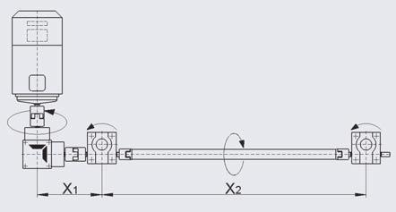
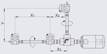
28 4. Selection, Calculation, Checklists With an application sketch and the completed checklist it will enable us to submit our quotation more speedily. 4.2 Checklist Page 1 Parameters Company: Address: Contact: Departement: Date Phone.: Fax: Number of pages: 1 Axial capacity in kn, max. per gearbox kn per system kn in tension kn in compression kn load: static kn dynamic kn installation position: vertical horizontal idle impact load vibration 2 Lift / Travel mm 3 Lifting speed Type N = 1.5 m/min. Type L = m/min. (MSZ1 and bigger: slightly different speeds) Customer s requirements m/min (many variants are possible) 4a Operating time, operating cycle lifts per day lifts per hour hours per day: 8 24 % operating time (ED) related to a min period, for permanent operating see checklist page 2 (4b). 5 Gear type: S standing spindle R rotating spindle 6 Standard arrangement no. Dimension X1 X2 X3 Y see standard arrangements, checklist pages 5 and 6! 7 Accessories YES NO see checklist page 3 or 4! 8 Motor: AC motor brake motor manual operation spring pressure brake incremental encoder linear measuring system limit switches (S version) 9 Application objective / Function description Description: Operating conditions: Dry Humid Dusty Chips Ambient operating temperature: min. C max. C Quantity: piece prototype first 11 Date: Offer: Delivery: 026 by ZIMM Austria 06
29 4. Selection, Calculation, Checklists 4.2 Checklist Page 2 Operating Times Only required for extended operating times and high duty cycles. 4b Operating cycle for permanent operations / operation times Diagrams with times in seconds or minutes, resulting operating period in percent %, with calculation 8 or 24 hours operation / day Example: operation time sec. up sec. still 5 sec. down 5 sec. still 5 sec. dwon 5 sec. 1 cycle 90 sec. still sec. Idle time in sec. min. hours Formula for calculating the relative operating period ED: ED = te x 0 ED in % (te+tp) ED= operating period te = operating time (in sec.) tp = idle time (in sec.) ED = sec. + 5 sec. + 5 sec. ( sec. + 5 sec. + 5 sec. + 5 sec. + 5 sec. + sec.) x 0 = 22,2% per hour when operated 8hr/day by ZIMM Austria
 Execution: SN (standing spindle, normal speed) SL (standing spindle, low speed) Tension load [kn] statically Tension load [kn] dynamically Compression load [kn] statically")
![Compression load [kn] dynamically Pivot bearing head Forked head Rod end Fixing flange Bellows Spiral spring base line Handwheel Motor with brake Motor without brake Coupling](/docs-images/81/83092984/images/30-1.jpg "Rotary pulse encoder Mounting bars Motor flange Safety nut Hinged bearing plate Limit switch Spring pressure brake Protective cap Lubrication strip Protection against rotation")
30 4. Selection, Calculation, Checklists 4.2 Checklist Page 3 Accessories S (also see overview chapter 3.3) Execution: SN (standing spindle, normal speed) SL (standing spindle, low speed) Tension load [kn] statically Tension load [kn] dynamically Compression load [kn] statically Compression load [kn] dynamically Pivot bearing head Forked head Rod end Fixing flange Bellows Spiral spring base line Handwheel Motor with brake Motor without brake Coupling Rotary pulse encoder Mounting bars Motor flange Safety nut Hinged bearing plate Limit switch Spring pressure brake Protective cap Lubrication strip Protection against rotation Escape Protection Protective tube Linear measuring system 028 by ZIMM Austria 06
 Execution: RN (rotating spindle, normal speed) RL (rotating spindle, low speed) Tension load [kn] statically Tension load [kn] dynamically Compression load [kn] statically")
![Compression load [kn] dynamically Opposed bearing plate Tension Compression Bellows Flat spiral spring covering on top on bottom Duplex nut DM1 Flange nut FM (trapezoid) Flange nut](/docs-images/81/83092984/images/31-1.jpg "KGTF Selfaligning nut PM1 Greaseless nut FFDM Driving flange TRMFL Safety nut Wear control Mounting bars Coupling base line Handwheel Motor Motor with brake Rotary pulse encoder")
31 4. Selection, Calculation, Checklists 4.2 Checklist Page 4 Accessories R (also see overview chapter 3.4) Execution: RN (rotating spindle, normal speed) RL (rotating spindle, low speed) Tension load [kn] statically Tension load [kn] dynamically Compression load [kn] statically Compression load [kn] dynamically Opposed bearing plate Tension Compression Bellows Flat spiral spring covering on top on bottom Duplex nut DM1 Flange nut FM (trapezoid) Flange nut KGTF Selfaligning nut PM1 Greaseless nut FFDM Driving flange TRMFL Safety nut Wear control Mounting bars Coupling base line Handwheel Motor Motor with brake Rotary pulse encoder Motor flange Hinged bearing plate Spring pressure brake Protective cap by ZIMM Austria


32 4. Selection, Calculation, Checklists 4.2 Checklist Page 5 Standard Arrangements by ZIMM Austria 06


33 4. Selection, Calculation, Checklists 4.2 Checklist Page 6 Standard Arrangements by ZIMM Austria


 acc.")

34 4. Selection, Calculation, Checklists 4.3 Critical Buckling Force of the Lifting Screw f k = 1 f k = 0, f k = 2 f k = 4 Version S guided lifting motion with hinged plate Version S non guided lifting motion, gear firmly mounted Version S guided lifting motion, gear firmly mounted Version R for a small L 1 there applies: f k = 2 guided lifting motion Critical buckling force F k in kn There is a buckling risk especially with gearboxes with long, thin spindles in combination with compression load. With the following calculation you can find the max. allowed axial load acc. to Euler. Maximum allowed axial load F all = 0,8 x F k x f k free length L in mm F all F k f k maximum allowable axial load (kn) theoretical critical buckling force (kn) acc. to diagram correction value (considers kind of bearing support, respectively guidance of lifting load) see pictograms above If the max calculated load is lower than required a larger spindle diameter could be selected. The calculations must then be reworked. With the rotating screw version a larger diameter screw can be selected (from the next bigger gearbox size). Any increase in pitch/ lifting speed must be taken into account. The safety factors for the type of system specified must be used, as shown above, to calculate the max allowable axial load for the system. 032 by ZIMM Austria 06

![speed n all = 0,8 x n kr x f kr unsupported screw lengths [m] spindle speed = input speed igearbox For R version gearboxes (with rotating spindle) with long, thin spindles it is necessary to](/docs-images/81/83092984/images/35-1.jpg "calculate the max. allowable spindle speed. Please take the theoretical critical speed nkr from the diagram. Also consider the additional lenghts for spindle covers, etc.")
35 4. Selection, Calculation, Checklists 4.4 Critical Whirling Speed of Spindle R Version theoretical spindle whirling speed nkr [min 1 ] with opposed bearing plate f kr = 1 without opposed bearing plate f kr = 0,5 Maximum allowable spindle speed n all = 0,8 x n kr x f kr unsupported screw lengths [m] spindle speed = input speed igearbox For R version gearboxes (with rotating spindle) with long, thin spindles it is necessary to calculate the max. allowable spindle speed. Please take the theoretical critical speed nkr from the diagram. Also consider the additional lenghts for spindle covers, etc. when calculating the unsupported screw lengths. Together with the correction factor for the bearing layout the max. allowable spindle speed can be calculated. If the calculated max spindle speed is lower than that required, a larger spindle should be selected. The calculations must then be reworked. If a larger diameter spindle is used in the R version the potential for higher drive torque's must be considered. The safety factors for the type of system specified must be used, as shown above, to calculate the max allowable axial load for the system. by ZIMM Austria
![4. Selection, Calculation, Checklists 4.5 Determining the Drive Torque [M G ] of a Lifting Gear With the formula shown below it is possible to calculate the necessary drive torque.](/docs-images/81/83092984/images/36-0.jpg "In order to facilitate the calculation of the drive torque we have determined multiplication factors out of this formula and have stated them in the technical data for the single gearbox version.")
36 4. Selection, Calculation, Checklists 4.5 Determining the Drive Torque [M G ] of a Lifting Gear With the formula shown below it is possible to calculate the necessary drive torque. In order to facilitate the calculation of the drive torque we have determined multiplication factors out of this formula and have stated them in the technical data for the single gearbox version. Formula 1) : M G F η Gearbox η Spindle P i M L P M Required drive torque [Nm] of a lifting gear Lifting load (dynamic) [kn] Efficiency of the lifting gear (without spindle) Efficiency of the spindle Spindle pitch [mm] Transmission of the lifting gear Idling torque [Nm] Power of motor Example: MSZSN F = kn (lifting load dynamic) η Gearbox = 0,87 η Spindle = 0,375 P = 6 i = 6 F [kn]. P [mm] Drive torque: M G = + M L [Nm] 2. π. η Gearbox. η Spindle. i M G = kn. 6mm 2. π. 0,87. 0, ,36 Nm = 6,21 Nm Power of motor: P M[kW] = M G [Nm]. n [min 1 ] 95 P M = 6,21 Nm. min 1 95 = 0,975 kw Safety factor (start torque) = calculated drive torque x 1.3 to 1.5 (for smaller systems use up to x 2).! Example: 0,975 kw. 1,4 = 1,365 kw motor 1,5 kw 1) For gearboxes with onepitch trapezoidal spindles it is also possible to multiply the factor which is stated on the corresponding gearbox page with the load. Tr Tr spindle η Spindle Efficiency single pitch P η lubricated 0,427 0,399 0,375 0,375 0,344 0,3 0,368 0,368 0,3 0,273 0,288 Tr Tr spindle η Spindle Efficiency double pitch P η lubricated 0,592 0,565 0,5 0,5 0,9 0,474 0,532 0,532 0,474 0,426 0,444 The efficiency of a trapezoid screw is substantially lower than that of ball screws due to friction. However, the trapezoid screw is technically more simple and more favourable. A safety device (e.g. a brake) is rarely required for trapezoid screws due to their selflocking MSZ N L MSZ N L 2 0,82 0,77 2 0,06 0,04 5 0,84 0,62 5 0, 0,08 0,86 0,69 0,26 0, 0,87 0,69 0,36 0,26 0,89 0,74 0,76 0,54 capability. With a ballscrew system an efficiency factor of η=0,9 can be used. It is essential to incorporate a break into a ballscrew system. Efficiency of gearboxes η Gearbox (without spindle) at n = 1.0 Idling torques M L of gearboxes [Nm] 0 0,85 0,65 0 1,68 1,02 1 0,84 0,67 1 1,90 1, 2 0,86 0,72 2 2,64 1,94 3 0,87 0,70 3 3,24 2, 0 0,84 0,62 0 3,96 2,84 6 0,85 0,65 6 5, 3, With ball screws you basically can calculate with an efficiency factor of η=0, by ZIMM Austria 06


37 4. Selection, Calculation, Checklists 4.6 Drive Torque for Gearboxes M R = M G x 2, Calculation The required drive torque of a lifting gear results from the sum of the moments of the individual lifting units. This is increased due to frictional losses of transmission components like couplings, connecting shafts, bevel gears, etc. To simplify the calculation, some factors for determining the drive torque in the most common applications are provided below. M R = M G x 2,1 M R = M G x 3,1 M R = M G x 3,35 M R = M G x 4,6 M R = M G x 6,8 M R = M G x 4,4 M R Total drive torque for the whole system M G Input torque of a single gearbox M A Starting torque max. 1,5 x M R M R = M G x 3,34 M R = M G x 3,27 Example (example from the left page, kn per gearbox) M R = M G x 4,6 = 6,21 Nm x 4,6 = 28,57 Nm x safety factor 1,3 = 37,Nm Attention: It is recommended to multiply the calculated value with a safety factor of 1.3 to 1.5 (for smaller systems factor up to 2). The indicated values are applicable in cases of uniform distribution of the lifting gear load onto all gears! by ZIMM Austria
 F A Axial load of the")
38 4. Selection, Calculation, Checklists 4.7 Maximum Power / Moments F Load definitions F Lifting load tension and/or compression F S Side forces on the spindle v H Lifting speed of the spindle (or nut of the R version) F A Axial load of the input shaft F R Radial load of the input shaft M R Drive torque n R Drive speed F S V H lifting screw F R Please examine the information on the following pages before making your choice of the lifting gear suited for your application. Various influences and assumptions can only be estimated on the basis of information gained by experience. In case of doubt please contact our sales engineers. M R n R F A input shaft = worm shaft Side forces on the spindle Please refer to the ajoining table for the maximum permissable side force. Side forces should be supported by a guidance system whenever possible. The bronze bushings in the gearbox are a secondary support only and should not be relied upon as adequate guidance. The maximum side force at a given screw extension must not exceed that stated in the ajoining table. Attention: only statically allowed! maximum side force F S [N] (static) MSZ extended screw length in mm Max. drive torque The stated values of the table on the right should not be exceeded. If gearboxes are arranged in tandem or in larger arrangements the maximum drive torque may be higher. If there are more than 5 gearboxes in an arrangement please contact our sales engineers. Radial load on the input shaft The radial forces of the table on the right should not be exceeded if you use chain drives or belt drives. maximum drive torque M R [Nm] Type M R SN/RN M R SN/RN M R SL/RL M R SL/RL min SHZ 02 0,7 1,0 0,5 0,7 MSZ 5 6,4,4 2,6 4,3 MSZ,6,5 5,3 8,4 MSZ 21,7 34,2 7,8,5 MSZ 44,7 70,3,5 24,5 MSZ 0 72,0 1,9 17,0 27,8 maximum radial load acting on the input shaft F R [N] F R max. SHZ MSZ 5 1 MSZ 2 MSZ 0 MSZ 5 MSZ MSZ 1 8 MSZ 1 67,3 7,0 17,3 27,7 MSZ 2 118,4 185,1 23,5 36,6 Consider that the starting torque is factor 1.5 of the operation torque Limit values are mechanical consider thermical factors depending on operating time MSZ 2 MSZ 3 187,0 295,7,2 63,9 MSZ 3 20 MSZ 0 4,3 3,6 42,8 71,2 MSZ MSZ 6 268,3 427,9 62,8 2,6 MSZ 7 4,0 663,0 83,0 132,0 MSZ by ZIMM Austria 06
39 4. Selection, Calculation, Checklists 4.8 Calculating Spindle and Protective Tube Lengths The following tables will allow calculation of the required spindle and protective tube length for the screw jack system selected. Basic Depending on gearbox version and system components the spindle (and protective tube for S version) have to be extended. These lengths are important. For non standard layouts please provide a drawing or contact the technical department. Stroke + basic length (+ extensions for variants/system components) Example S: MSZSN, stroke: 2 mm bellow MSZFB0 (compression ZD=70mm) fixing flange BF (therefore bellow without retainer) protection against rotation VS limit switch ESSET Spindle length Tr: = 517 mm stroke basic length bellow limit switch spindle length (7027=43) + protection against rotation protective tube length SRO: = 376 stroke basic length limit switch protective tube length + protection against rotation Example R: MSZRN, stroke 2 mm spindle with pilot (opposed bearing plate GLP) bellow MSZFB0 (compression ZD=70mm) below and above duplex nut DM Spindle length Tr: = 5 mm stroke basic length bellow gearboxsided 2. bellow duplex nut spindle length (70=) (70=55) Length calculation for connecting shafts can be found in chapter.4. by ZIMM Austria
40 4. Selection, Calculation, Checklists 4.8 Length Calculation, Standing Version S Spindle spindle extension S version below gearbox (tube side) Tr basic length Tr basic length with safety nut Tr basic length AntiBacklash KGT basic length Escape prot./prot. against rot. (evtl. WMS) Limit switch3) (+evtl. linear measuring syst.) ES3) and hinged bearing plate (evtl. WMS) MSZ5 139 x05 3 x MSZ 1 x x 8 x 328 x MSZ x x x 3 32x MSZ 2 x x 326 x 356 x MSZ0 3 x 4 x MSZ x MSZ MSZ MSZ MSZ spindle extension S version above gearbox Bellows with bushing (GK / KGK)1) Bellows without bushing (BF / SLK)1) Bellows and KAR with FBR (GK / KGK)1) Bellows and KAR without FBR (BF / SLK)1) MSZ05 ZD 2 ZD 22 ZD +32 ZD + MSZ ZD +1 ZD 24 ZD +34 ZD +9 MSZ ZD +5 ZD 27 ZD +53 ZD +22 MSZ ZD + ZD 36 ZD +67 ZD +21 MSZ0 ZD +8 ZD ZD +81 ZD +33 MSZ1 ZD +2 ZD 18 ZD +71 ZD +51 MSZ2 ZD +2 ZD 18 ZD +93 ZD +73 MSZ3 ZD +2 ZD 18 ZD +1 ZD +94 MSZ0 ZD +2 ZD 18 ZD +136 ZD +1 MSZ6 2) ZD +2 ZD 18 ZD +8 ZD +8 ZDMeasures: see capter.3.5 Safety distances are already included in basic lengths! (Tr spindle: mm up to MSZ0, mm from MSZ1, for KGT see chapter 9.1, dimension L3) 1) The value will be added or subtracted to the ZD dimension of the bellow the result will then be added to the spindle lenght. (e.g. ZD = 70 >> ZD22 = 48 mm >> spindle extension for bellow is 48 mm) 2) Bellow, bellow ring and bellow adapter are similar to MSZ0 3) Limit switches ES are always in combination with protection against rotation VS (VS is in the extension included) Spindle extension for spiral spring covering SF: As the extension of the spiral spring covering differs depending on the attachment, this variant has to be calculated graphically. If necessary we would be pleased to generate this drawing. Abbreviations: AS Escape protection KAR Hinged bearing plate BF Fixing flange KGK Rod end ES Limit switch SLK Pivot bearing head FBR Bellows connecting ring WMS Linear measuring system GK Forked head ZD Compression 038 by ZIMM Austria 06
41 4. Selection, Calculation, Checklists 4.8 Length Calculation, Standing Version S Protective Tube SRO protective tube extension S version Tr basic length 1) KGT basic length 1) Escape prot./prot. ag. rotat. AS/VS Limit switch ES3) (+ evtl. WMS) + VS ES 3) and hinged bearing plate KAR VS + Linear measuring system WMS MSZ5 48 x05 x MSZ x05 x 80 x 1 x MSZ 55 32x x 75 32x 5 32x MSZ 64 x05 74 x 74 x 4 x MSZ0 75 x 95 x MSZ x MSZ MSZ MSZ ) Basic length of protective tube without cap to achieve the whole protective tube length add another 5mm for the cap Attention: minimum stroke with limit switch ES: min.stroke with limit switch ES 3) 2) min.stroke with ES3) + lubric. strip 2) ) Is a lower stroke required as stated above, the limit swithces and the lubrication strips have to be mounted on two different sides (assembly position)! 3) Limit switches ES are always in combination with protection against rotation VS (VS is in the extension included) MSZ by ZIMM Austria
42 4. Selection, Calculation, Checklists 4.8 Length Calculation, Rotating Version R Spindle Spindle extension R version Tr basic length without machined end Tr basic length with machined end (= standard for opposed bearing plate GLP) Tr basic length larger diameter with machined end 1) KGT basic length without machined end 2) (including nut) KGT basic length larger diameter without machined end 2) (including nut) KGT basic lenth with machined end 2) (including nut) KGT basic length larger diameter without machined end 2) (including nut) Flange nut FM Duplex nut DM Selfaligning nut PM Greaseless nut FFDM DM + Safety nut SIFA PM + Safety nut SIFA 1. FB gearboxnut 5) 2. FB nutopposite bearing plate 5) KAR6) spindlesided and1. bellow 5) MSZ x05 5 x 178 x05 5 x 178 x 228 x 381 x05 1 x 193 x05 5 x 198 x 248 x ZD ZD ZD +18 MSZ x05 8 x 191 x 241 x x x x x 271 x x 211 x 261 x 4 32x x 2 32x x ZD ZD ZD +18 MSZ x x 9 32x 2 32x 285 x x 1 x 2 x 5 32x x x x 3 x x 231 x 270 x ZD ZD ZD +32 MSZ 3 8 x05 2 x 244 x 283 x 348 x 278 x 318 x05 2 x 274 x 313 x 378 x 323 x ZD ZD ZD +32 MSZ x 327 x x x 422 x 372 x 4 63x 7 63x ZD ZD ZD +46 MSZ x x x x3) x4) x x 4 80x x3) x4) ZD 18 ZD 26 ZD +42 MSZ x 7 80x3) x4) 2 80x x3) x4) ZD 18 ZD 36 ZD +65 MSZ ZD 18 ZD 56 ZD +80 MSZ ZD 18 ZD 21 ZD +0 MSZ ZD 18 ZD 41 ZD +99 Safety distances are already included in basic lengths! (Tr spindle: mm up to MSZ0, mm from MSZ1, for KGT see chapter 9.1, dimension L3) 1) When using a larger diameter spindle also select the system components of the next bigger gearbox. (MSZ with larger diameter spindle has spindle Trx6, system components of MSZ therefore also calculational spindle extension of gearbox size ). 2) The basic length of KGT spindles includes the length of the KGT nut and the safety distance according to ZIMM catalogue (see chapter 9.2, size L3). 3) KGT nut with dynamic load rating 135kN and static load rating 322kN (80x4EP). 4) KGT nut with dynamic load 1,5kN and static load rating 398kN (80x5EP). 5) The value will be depending on the algebraic sign added or subtracted of the ZD (compression) dimension of the bellow the result will then be added to the spindle lenght. 6) KAR is the hinged bearing plate Spindle extension for spiral spring covering SF: As the extension of the spiral spring covering differs depending on the attachment, this variant has to be calculated graphically. If necessary we would be pleased to generate this drawing. 0 by ZIMM Austria 06
43 4. Selection, Calculation, Checklists 4.9 Order Code MSZ Millennium Series ZIMM Size Housing material Version Ratio Version of thread SpindleØ / Pitch Number of gears, material Stroke MSZ H MSZ G Grey cast iron GG Heavy duty design (not specified = G) A Aluminium S Steel (MSZ 7) S Standing version R Rotating version N Normal e.g. i = 4:1 L Low e.g. i = :1 TR Trapezoidal spindle (not specified = Tr) > chapters 5 and 6 TR/SIFA Tr with safety nut SIFA > chapter 8 TR/AB Tr, AntiBacklash AB (only with S version) > chapter KGT Ball screws > chapter 9 TR/SIFAVU with wear control TR/SIFADU with rotation control TR/SIFAVU/DU with rotaion + wear control TR KGT pitch (not specified = 1pitch) 2 * 2pitch I INOX (stainless) LH * leftthreaded *) available, but not from stock. Delivery time on request Stroke H + stroke in mm List of system components List of system components (order does not matter) > chapter Size Material housing Version S or R Ratio N or L Version of thread Spindle diameter Spindle pitch Number of gears Stroke List of system components (order does not matter) Order expample: MSZ G SN TR/SIFA 04 1 H 0 FB390 VS BF by ZIMM Austria
 i Stroke per revolution 5) MSZ5SN MSZ5SL Standing Screw Normal Low Tr 18x4 4:1 :1 1,00 mm 0, mm")


44 5. Heavy Duty Screw Jacks MSZ 5kN MSZ5 Standing Screw S 5kN deep base line deep Basic Versions Tr Version Type Speed Standard Screw 2) i Stroke per revolution 5) MSZ5SN MSZ5SL Standing Screw Normal Low Tr 18x4 4:1 :1 1,00 mm 0, mm MSZ5RN MSZ5RL Rotating Screw Normal Low Tr 18x4 4:1 :1 1,00 mm 0, mm 1) with bellows or spiral spring extension: see chapter 4 Standard types S Standard types R Basic model S Heavy duty screw jack grey cast housing Ball screw KGT Basic model R Heavy duty screw jack grey cast housing Safety nut SIFA Ball Screw KGT Aluminium housing KGT x 5 KGT x Aluminium housing wear control of the nut KGT x 5 KGT x capter 7 capter 9 capter 7 capter 8 capter by ZIMM Austria 06
 + 5 mm System components are presented in chapter A minimum of mm safety clearance is required between the nut + gearbox / nut + end mounting to prevent dammage due to possible overun.")
 Screw dimension Tr 18x4 2) Gear reduction 4:1 (N) / :1 (L) Material of box GG grey cast Lubrication grease Weight of lifting gear 1,70 kg Weight of")
![spindle/m 1,58 kg Drive torque M G [Nm] F [kn] x 0,62 3)5) + M L (NNormal) F [kn] x 0,21 3)5) + M L (LLow) Starting torque drive torque M G x 1,5 Idle torque 4) ML [Nm] 0, (NNormal) 0,08 (LLow)](/docs-images/81/83092984/images/45-2.jpg "Important notes 1) For bellows or spiral spring extensions: see chapter 4 2) Tr18x4 is standard, also available: 2pitch, INOX, lefthanded, larger diameter spindle Trx4 (only for R version) 3) Factor")
45 5. Heavy Duty Screw Jack MSZ 5kN MSZ5 Rotating Screw R 5kN deep base line deep deep x = calculated spindle length (chapter 4.8) + 5 mm System components are presented in chapter A minimum of mm safety clearance is required between the nut + gearbox / nut + end mounting to prevent dammage due to possible overun. Selection, calculation, checklists and order code: see chapter 4 Technical data S and R Max. pressure/tensile force static 5 kn (0,5 t) Max. drive shaft speed 1800 min 1 (higher on request) Screw dimension Tr 18x4 2) Gear reduction 4:1 (N) / :1 (L) Material of box GG grey cast Lubrication grease Weight of lifting gear 1,70 kg Weight of spindle/m 1,58 kg Drive torque M G [Nm] F [kn] x 0,62 3)5) + M L (NNormal) F [kn] x 0,21 3)5) + M L (LLow) Starting torque drive torque M G x 1,5 Idle torque 4) ML [Nm] 0, (NNormal) 0,08 (LLow) Important notes 1) For bellows or spiral spring extensions: see chapter 4 2) Tr18x4 is standard, also available: 2pitch, INOX, lefthanded, larger diameter spindle Trx4 (only for R version) 3) Factor includes efficiency, ratio and % safety 4) May be higher in new condition 5) At spindle pitch of 4mm Capacity diagram stat./dyn. S and R [kn] load static dynamic basis: C operating time in % per N = Normal speed L = Low speed This diagram indicates the maximum capacity (under optimal conditions). Where duty or load are near upper limits we recommend the selection of a bigger gearbox. The maximum duty cycle is affected by many factors: e.g.: lubrication, environment temperature, bellows, etc. by ZIMM Austria
 with bellows or spiral spring extension: see chapter 4 Standard Types S Standard Types R Basic model")
46 5. Heavy Duty Screw Jack MSZ kn MSZ Standing Screw S kn deep base line deep deep Basic Versions Tr Version Type Speed Standard i Stroke per Screw 2) revolution 5) MSZSN MSZSL Standing Screw Normal Low Tr x4 4:1 :1 1,00 mm 0, mm MSZRN MSZRL Rotating Screw Normal Low Tr x4 4:1 :1 1,00 mm 0, mm 1) with bellows or spiral spring extension: see chapter 4 Standard Types S Standard Types R Basic model S Heavy duty screw jack grey cast housing Safety nut SIFA Ball screw KGT AntiBacklash AB Basic model R Heavy duty screw jack grey cast housing Safety nut SIFA Ball screw KGT GGhousing Aluminium housing rotation control and wear control of the nut KGT x 5 KGT x KGT x KGT x adjustable antibacklash GGhousing Aluminium housing wear control of the nut KGT x 5 KGT x KGT x KGT x this page capter 7 capter 8 capter 9 capter this page capter 7 capter 8 capter by ZIMM Austria 06
 + 8 mm System components are presented in chapter A minimum of mm safety clearance is required between the nut + gearbox / nut + end mounting to prevent dammage due to possible overun.")
 Screw dimension Tr x4 2) Gear reduction 4:1 (N) / :1 (L) Material of box GG grey cast Lubrication grease Weight of lifting gear 3 kg Weight of")
47 5. Heavy Duty Screw Jack MSZ kn MSZ Rotating Screw R kn deep base line deep deep x = calculated spindle length (chapter 4.8) + 8 mm System components are presented in chapter A minimum of mm safety clearance is required between the nut + gearbox / nut + end mounting to prevent dammage due to possible overun. Selection, calculation, checklists and order code: see chapter 4 Technical data S and R Max. pressure/tensile force static kn (1 t) Max. drive shaft speed 1800 min 1 (higher on request) Screw dimension Tr x4 2) Gear reduction 4:1 (N) / :1 (L) Material of box GG grey cast Lubrication grease Weight of lifting gear 3 kg Weight of spindle/m 2 kg Drive torque M G [Nm] F [kn] x 0,64 3)5) + M L (NNormal) F [kn] x 0, 3)5) + M L (LLow) Starting torque drive torque M G x 1,5 Idle torque 4) ML [Nm] 0,26 (NNormal) 0, (LLow) Important notes 1) For bellows or spiral spring extensions: see chapter 4 2) Trx4 is standard, also available: 2pitch, INOX, lefthanded, larger diameter spindle Trx6 (only for R version) 3) Factor includes efficiency, ratio and % safety 4) May be higher in new condition 5) At spindle pitch of 4mm Capacity diagram stat./dyn. S and R [kn] load static dynamic basis: C operating time in % per N = Normal speed L = Low speed This diagram indicates the mascimum capacity (under optimal conditions). Where duty or load are near upper limits we recommend the selection of a bigger gearbox. The maximum duty cycle is affected by many factors: e.g.: lubrication, environment temperature, bellows, etc. by ZIMM Austria
 with bellows or spiral spring extension: see chapter 4 Standard Types S Standard Types R Basic")
48 5. Heavy Duty Screw Jack MSZ kn MSZ Standing Screw S kn deep base line deep deep Basic Versions Tr Version Type Speed Standard Screw 2) i Stroke per revolution 5) MSZSN MSZSL Standing Screw Normal Low Tr x6 6:1 24:1 1,00 mm 0, mm MSZRN MSZRL Rotating Screw Normal Low Tr x6 6:1 24:1 1,00 mm 0, mm 1) with bellows or spiral spring extension: see chapter 4 Standard Types S Standard Types R Basic model S Heavy duty screw jack grey cast housing Safety nut SIFA Ball screw KGT AntiBacklash AB Basic model R Heavy duty screw jack grey cast housing Safety nut SIFA Ball screw KGT Aluminium housing rotation control and wear control of the nut KGT 32 x 5 KGT 32 x KGT 32 x KGT 32 x adjustable antibacklash Aluminium housing wear control of the nut KGT 32 x 5 KGT 32 x KGT 32 x KGT 32 x capter 7 capter 8 capter 9 capter caper 7 capter 8 capter by ZIMM Austria 06
 + 5 mm System components are presented in chapter A minimum of mm safety clearance is required between the nut + gearbox / nut + end mounting to prevent dammage due to possible overun.")
 Screw dimension Tr x6 2) Gear reduction 6:1 (N) / 24:1 (L) Material of box GG grey cast Lubrication grease Weight of lifting gear 6,5 kg Weight of")
49 5. Heavy Duty Screw Jack MSZ kn MSZ Rotating Screw R kn deep base line deep deep x = calculated spindle length (chapter 4.8) + 5 mm System components are presented in chapter A minimum of mm safety clearance is required between the nut + gearbox / nut + end mounting to prevent dammage due to possible overun. Selection, calculation, checklists and order code: see chapter 4 Technical data S and R Max. pressure/tensile force static kn (2,5 t) Max. drive shaft speed 1800 min 1 (higher on request) Screw dimension Tr x6 2) Gear reduction 6:1 (N) / 24:1 (L) Material of box GG grey cast Lubrication grease Weight of lifting gear 6,5 kg Weight of spindle/m 4,5 kg Drive torque M G [Nm] F [kn] x 0,63 3)5) + M L (NNormal) F [kn] x 0, 3)5) + M L (LLow) Starting torque drive torque M G x 1,5 Idle torque 4) ML [Nm] 0,36 (NNormal) 0,26 (LLow) Important notes 1) For bellows or spiral spring extensions: see chapter 4 2) Trx6 is standard, also available: 2pitch, INOX, lefthanded, larger diameter spindle Trx7 (only for R version) 3) Factor includes efficiency, ratio and % safety 4) May be higher in new condition 5) At spindle pitch of 6mm Capacity diagram stat./dyn. S and R [kn] load static dynamic basis: C operating time in % per N = Normal speed L = Low speed This diagram indicates the mascimum capacity (under optimal conditions). Where duty or load are near upper limits we recommend the selection of a bigger gearbox. The maximum duty cycle is affected by many factors: e.g.: lubrication, environment temperature, bellows, etc. by ZIMM Austria
 with bellows or spiral spring extension: see chapter 4 Standard Types S Standard Types R Basic")
50 5. Heavy Duty Screw Jack MSZ kn MSZ Standing Screw S kn deep deep base line deep Basic Versions Tr Version Type Speed Standard Screw 2) i Stroke per revolution 5) MSZSN MSZSL Standing Screw Normal Low Tr x7 7:1 28:1 1,00 mm 0, mm MSZRN MSZRL Rotating Screw Normal Low Tr x7 7:1 28:1 1,00 mm 0, mm 1) with bellows or spiral spring extension: see chapter 4 Standard Types S Standard Types R Basic model S Heavy duty screw jack grey cast housing Safety nut SIFA Ball screw KGT AntiBacklash AB Basic model R Heavy duty screw jack grey cast housing Safety nut SIFA Ball screw KGT rotation control and wear control of the nut KGT x 5 KGT x KGT x KGT x adjustable antibacklash wear control of the nut KGT x 5 KGT x KGT x KGT x capter 8 capter 9 capter capter 8 capter by ZIMM Austria 06
 + 6 mm System components are presented in chapter A minimum of mm safety clearance is required between the nut + gearbox / nut + end mounting to prevent dammage due to possible overun.")
 Screw dimension Tr x7 2) Gear reduction 7:1 (N) / 28:1 (L) Material of box GG grey cast Lubrication grease Weight of lifting gear kg Weight of")
51 5. Heavy Duty Screw Jack MSZ kn MSZ Rotating Screw R kn deep deep base line deep x = calculated spindle length (chapter 4.8) + 6 mm System components are presented in chapter A minimum of mm safety clearance is required between the nut + gearbox / nut + end mounting to prevent dammage due to possible overun. Selection, calculation, checklists and order code: see chapter 4 Technical data S and R Max. pressure/tensile force static kn (5 t) Max. drive shaft speed 1800 min 1 (higher on request) Screw dimension Tr x7 2) Gear reduction 7:1 (N) / 28:1 (L) Material of box GG grey cast Lubrication grease Weight of lifting gear kg Weight of spindle/m 8 kg Drive torque M G [Nm] F [kn] x 0,68 3)5) + M L (NNormal) F [kn] x 0, 3)5) + M L (LLow) Starting torque drive torque M G x 1,5 Idle torque 4) ML [Nm] 0,76 (NNormal) 0,54 (LLow) Important notes 1) For bellows or spiral spring extensions: see chapter 4 2) Trx7 is standard, also available: 2pitch, INOX, lefthanded, larger diameter spindle Trx8 (only for R version) 3) Factor includes efficiency, ratio and % safety 4) May be higher in new condition 5) At spindle pitch of 7mm Capacity diagram stat./dyn. S and R [kn] load static dynamic basis: C operating time in % per N = Normal speed L = Low speed This diagram indicates the mascimum capacity (under optimal conditions). Where duty or load are near upper limits we recommend the selection of a bigger gearbox. The maximum duty cycle is affected by many factors: e.g.: lubrication, environment temperature, bellows, etc. by ZIMM Austria
 with bellows or spiral spring extension: see chapter 4 Standard Types S Standard Types")
52 5. Heavy Duty Screw Jack MSZ 0kN MSZ0 Standing Screw S 0kN deep deep base line deep Basic Versions Tr Version Type Speed Standard Screw 2) i Stroke per revolution 5) MSZ0SN MSZ0SL Standing Screw Normal Low Tr x8 8:1 32:1 1,00 mm 0, mm MSZ0RN MSZ0RL Rotating Screw Normal Low Tr x8 8:1 32:1 1,00 mm 0, mm 1) with bellows or spiral spring extension: see chapter 4 Standard Types S Standard Types R Basic model S Heavy duty screw jack grey cast housing Safety nut SIFA Ball screw KGT AntiBacklash AB Basic model R Heavy duty screw jack grey cast housing Safety nut SIFA Ball screw KGT rotation control and wear control of the nut KGT x KGT x adjustable antibacklash wear control of the nut KGT x KGT x capter 8 capter 9 capter capter 8 capter 9 0 by ZIMM Austria 06
 + mm System components are presented in chapter A minimum of mm safety clearance is required between the nut + gearbox / nut + end mounting to prevent dammage due to possible overun.")
 Screw dimension Tr x8 2) Gear reduction 8:1 (N) / 32:1 (L) Material of box GG grey cast Lubrication grease Weight of lifting gear 33 kg Weight of")
53 5. Heavy Duty Screw Jack MSZ 0kN MSZ0 Rotating Screw R 0kN deep deep base line deep x = calculated spindle length (chapter 4.8) + mm System components are presented in chapter A minimum of mm safety clearance is required between the nut + gearbox / nut + end mounting to prevent dammage due to possible overun. Selection, calculation, checklists and order code: see chapter 4 Technical data S and R Max. pressure/tensile force static 0 kn ( t) Max. drive shaft speed 1800 min 1 (higher on request) Screw dimension Tr x8 2) Gear reduction 8:1 (N) / 32:1 (L) Material of box GG grey cast Lubrication grease Weight of lifting gear 33 kg Weight of spindle/m 13 kg Drive torque M G [Nm] F [kn] x 0,78 3)5) + M L (NNormal) F [kn] x 0, 3)5) + M L (LLow) Starting torque drive torque M G x 1,5 Idle torque 4) ML [Nm] 1,68 (NNormal) 1,02 (LLow) Important notes 1) For bellows or spiral spring extensions: see chapter 4 2) Trx8 is standard, also available: 2pitch, INOX, lefthanded, larger diameter spindle Trx (only for R version) 3) Factor includes efficiency, ratio and % safety 4) May be higher in new condition 5) At spindle pitch of 8mm Capacity diagram stat./dyn. S and R [kn] load static dynamic basis: C operating time in % per N = Normal speed L = Low speed This diagram indicates the mascimum capacity (under optimal conditions). Where duty or load are near upper limits we recommend the selection of a bigger gearbox. The maximum duty cycle is affected by many factors: e.g.: lubrication, environment temperature, bellows, etc. by ZIMM Austria
 with bellows or spiral spring extension: see chapter 4 Standard Types S")
54 6. Heavy Duty Screw Jack MSZ 1kN MSZ1 Standing Screw S 1kN M42x2 deep deep base line deep Basic Versions Tr Version Type Speed Standard Screw 2) i Stroke per revolution 5) MSZ1SN MSZ1SL Standing Screw Normal Low Tr x 9:1 36:1 1,33 mm 0,33 mm MSZ1RN MSZ1RL Rotating Screw Normal Low Tr x 9:1 36:1 1,33 mm 0,33 mm 1) with bellows or spiral spring extension: see chapter 4 Standard Types S Standard Types R Basic model S Heavy duty screw jack grey cast housing Safety nut SIFA Ball screw KGT AntiBacklash AB Basic model R Heavy duty screw jack grey cast housing Safety nut SIFA Ball screw KGT rotation control and wear control of the nut KGT 63x adjustable antibacklash wear control of the nut KGT 63 x KGT 63 x capter 8 capter 9 capter capter 8 capter by ZIMM Austria 06
 + 8 mm System components are presented in chapter A minimum of mm safety clearance is required between the nut + gearbox / nut + end mounting to prevent dammage due to possible overun.")
 Screw dimension Tr x 2) Gear reduction 9:1 (N) / 36:1 (L) Material of box GG grey cast Lubrication grease Weight of lifting gear 42 kg Weight of")
55 6. Heavy Duty Screw Jack MSZ 1kN MSZ1 Rotating Screw R 1kN deep deep base line deep x = calculated spindle length (chapter 4.8) + 8 mm System components are presented in chapter A minimum of mm safety clearance is required between the nut + gearbox / nut + end mounting to prevent dammage due to possible overun. Selection, calculation, checklists and order code: see chapter 4 Technical data S and R Max. pressure/tensile force static 1 kn ( t) Max. drive shaft speed 1800 min 1 (higher on request) Screw dimension Tr x 2) Gear reduction 9:1 (N) / 36:1 (L) Material of box GG grey cast Lubrication grease Weight of lifting gear 42 kg Weight of spindle/m 18 kg Drive torque M G [Nm] F [kn] x 0,89 3)5) + M L (NNormal) F [kn] x 0,28 3)5) + M L (LLow) Starting torque drive torque M G x 1,5 Idle torque 4) ML [Nm] 1,90 (NNormal) 1, (LLow) Important notes 1) For bellows or spiral spring extensions: see chapter 4 2) Trx is standard, also available: 2pitch, INOX, lefthanded, larger diameter spindle Tr80x (only for R version) 3) Factor includes efficiency, ratio and % safety 4) May be higher in new condition 5) At spindle pitch of mm Capacity diagram stat./dyn. S and R [kn] load static dynamic basis: C operating time in % per N = Normal speed L = Low speed This diagram indicates the mascimum capacity (under optimal conditions). Where duty or load are near upper limits we recommend the selection of a bigger gearbox. The maximum duty cycle is affected by many factors: e.g.: lubrication, environment temperature, bellows, etc. by ZIMM Austria
 with bellows or spiral spring extension: see chapter 4 Standard Types S Standard Types R")
56 6. Heavy Duty Screw Jack MSZ 2kN MSZ2 Standing Screw S 2kN M56x2 deep deep base line deep Basic Versions Tr Version Type Speed Standard Screw 2) i Stroke per revolution 5) MSZ2SN MSZ2SL Standing Screw Normal Low Tr 80x :1 :1 1, mm 0, mm MSZ2RN MSZ2RL Rotating Screw Normal Low Tr 80x :1 :1 1, mm 0, mm 1) with bellows or spiral spring extension: see chapter 4 Standard Types S Standard Types R Basic model S Heavy duty screw jack grey cast housing Safety nut SIFA AntiBacklash AB Basic model R Heavy duty screw jack grey cast housing Safety nut SIFA Ball screw KGT rotation control and wear control of the nut adjustable antibacklash wear control of the nut KGT 80 x KGT 80 x capter 8 capter capter 8 capter by ZIMM Austria 06
 + mm System components are presented in chapter A minimum of mm safety clearance is required between the nut + gearbox / nut + end mounting to prevent dammage due to possible overun.")
 Screw dimension Tr 80x 2) Gear reduction :1 (N) / :1 (L) Material of box GG grey cast Lubrication grease Weight of lifting gear 57 kg Weight of")
57 6. Heavy Duty Screw Jack MSZ 2kN MSZ2 Rotating Screw R 2kN deep deep base line deep x = calculated spindle length (chapter 4.8) + mm System components are presented in chapter A minimum of mm safety clearance is required between the nut + gearbox / nut + end mounting to prevent dammage due to possible overun. Selection, calculation, checklists and order code: see chapter 4 Technical data S and R Max. pressure/tensile force static 2 kn ( t) Max. drive shaft speed 1800 min 1 (higher on request) Screw dimension Tr 80x 2) Gear reduction :1 (N) / :1 (L) Material of box GG grey cast Lubrication grease Weight of lifting gear 57 kg Weight of spindle/m 42 kg Drive torque M G [Nm] F [kn] x 1,05 3)5) + M L (NNormal) F [kn] x 0,31 3)5) + M L (LLow) Starting torque drive torque M G x 1,5 Idle torque 4) ML [Nm] 2,64 (NNormal) 1,94 (LLow) Important notes 1) For bellows or spiral spring extensions: see chapter 4 2) Tr80x is standard, also available: 2pitch, INOX, lefthanded, larger diameter spindle Tr0x (only for R version) 3) Factor includes efficiency, ratio and % safety 4) May be higher in new condition 5) At spindle pitch of mm Capacity diagram stat./dyn. S and R [kn] load static dynamic basis: C operating time in % per N = Normal speed L = Low speed This diagram indicates the mascimum capacity (under optimal conditions). Where duty or load are near upper limits we recommend the selection of a bigger gearbox. The maximum duty cycle is affected by many factors: e.g.: lubrication, environment temperature, bellows, etc. by ZIMM Austria
 with bellows or spiral spring extension: see chapter 4 Standard Types S Standard Types R Basic")
58 6. Heavy Duty Screw Jack MSZ 3kN MSZ3 Standing Screw S 3kN deep deep base line deep Basic Versions Tr Version Type Speed Standard Screw 2) i Stroke per revolution 5) MSZ3SN MSZ3SL Standing Screw Normal Low Tr 0x :1 :1 1, mm 0, mm MSZ3RN MSZ3RL Rotating Screw Normal Low Tr 0x :1 :1 1, mm 0, mm 1) with bellows or spiral spring extension: see chapter 4 Standard Types S Standard Types R Basic model S Heavy duty screw jack grey cast housing Safety nut SIFA AntiBacklash AB Basic model R Heavy duty screw jack grey cast housing Safety nut SIFA rotation control and wear control of the nut capter 8 adjustable antibacklash capter wear control of the nut capter by ZIMM Austria 06
 + 7 mm System components are presented in chapter A minimum of mm safety clearance is required between the nut + gearbox / nut + end mounting to prevent dammage due to possible overun.")
 Screw dimension Tr 0x 2) Gear reduction :1 (N) / :1 (L) Material of box GG grey cast Lubrication grease Weight of lifting gear 87 kg Weight of")
59 6. Heavy Duty Screw Jack MSZ 3kN MSZ3 Rotating Screw R 3kN deep deep base line deep x = calculated spindle length (chapter 4.8) + 7 mm System components are presented in chapter A minimum of mm safety clearance is required between the nut + gearbox / nut + end mounting to prevent dammage due to possible overun. Selection, calculation, checklists and order code: see chapter 4 Technical data S and R Max. pressure/tensile force static 3 kn (35 t) Max. drive shaft speed 1800 min 1 (higher on request) Screw dimension Tr 0x 2) Gear reduction :1 (N) / :1 (L) Material of box GG grey cast Lubrication grease Weight of lifting gear 87 kg Weight of spindle/m 66 kg Drive torque M G [Nm] F [kn] x 1,21 3)5) + M L (NNormal) F [kn] x 0,38 3)5) + M L (LLow) Starting torque drive torque M G x 1,5 Idle torque 4) ML [Nm] 3,24 (NNormal) 2, (LLow) Important notes 1) For bellows or spiral spring extensions: see chapter 4 2) Tr0x is standard, also available: 2pitch, INOX, lefthanded, larger diameter spindle Tr1x (only for R version) 3) Factor includes efficiency, ratio and % safety 4) May be higher in new condition 5) At spindle pitch of mm Capacity diagram stat./dyn. S and R [kn] load static dynamic basis: C operating time in % per N = Normal speed L = Low speed This diagram indicates the mascimum capacity (under optimal conditions). Where duty or load are near upper limits we recommend the selection of a bigger gearbox. The maximum duty cycle is affected by many factors: e.g.: lubrication, environment temperature, bellows, etc. by ZIMM Austria
 with bellows or spiral spring")

60 6. Heavy Duty Screw Jack MSZ 0kN MSZ0 Standing Screw S 0kN deep base line deep Basic Versions Tr Version Type Speed Standard Screw 2) i Stroke per revolution 5) MSZ0SN MSZ0SL Standing Screw Normal Low Tr 1x :1 56:1 1,3 mm 0,286 mm MSZ0RN MSZ0RL Rotating Screw Normal Low Tr 1x :1 56:1 1,3 mm 0,286 mm 1) with bellows or spiral spring extension: see chapter 4 Standard Types S Standard Types R Basic model S Heavy duty screw jack grey cast housing Safety nut SIFA AntiBacklash AB Basic model R Heavy duty screw jack grey cast housing Safety nut SIFA rotation control and wear control of the nut adjustable antibacklash wear control of the nut capter 8 capter capter by ZIMM Austria 06
 + 8 mm System components are presented in chapter A minimum of mm safety clearance is required between the nut + gearbox / nut + end mounting to prevent dammage due to possible overun.")
 Screw dimension Tr 1x 2) Gear reduction :1 (N) / 56:1 (L) Material of box GG grey cast Lubrication grease Weight of lifting gear 5 kg Weight of")
61 6. Heavy Duty Screw Jack MSZ 0kN MSZ0 Rotating Screw R 0 kn deep base line deep x = calculated spindle length (chapter 4.8) + 8 mm System components are presented in chapter A minimum of mm safety clearance is required between the nut + gearbox / nut + end mounting to prevent dammage due to possible overun. Selection, calculation, checklists and order code: see chapter 4 Technical data S and R Max. pressure/tensile force static 0 kn ( t) Max. drive shaft speed 1800 min 1 (higher on request) Screw dimension Tr 1x 2) Gear reduction :1 (N) / 56:1 (L) Material of box GG grey cast Lubrication grease Weight of lifting gear 5 kg Weight of spindle/m 78 kg Drive torque M G [Nm] F [kn] x 1,03 3)5) + M L (NNormal) F [kn] x 0,35 3)5) + M L (LLow) Starting torque drive torque M G x 1,5 Idle torque 4) ML [Nm] 3,96 (NNormal) 2,84 (LLow) Important notes 1) For bellows or spiral spring extensions: see chapter 4 2) Tr1x is standard, also available: 2pitch, INOX, lefthanded, larger diameter spindle Tr1x (only for R version) 3) Factor includes efficiency, ratio and % safety 4) May be higher in new condition 5) At spindle pitch of mm Capacity diagram stat./dyn. S and R [kn] load static dynamic basis: C operating time in % per N = Normal speed L = Low speed This diagram indicates the mascimum capacity (under optimal conditions). Where duty or load are near upper limits we recommend the selection of a bigger gearbox. The maximum duty cycle is affected by many factors: e.g.: lubrication, environment temperature, bellows, etc. by ZIMM Austria
 with bellows or spiral spring extension: see chapter 4 Standard Types S Standard Types R Basic")
62 6. Heavy Duty Screw Jack MSZ 6kN MSZ6 Standing Screw S 6kN base line deep Basic Versions Tr Version Type Speed Standard Screw 2) i Stroke per revolution 5) MSZ6SN MSZ6SL Standing Screw Normal Low Tr 1x :1 56:1 1,429 mm 0,357 mm MSZ6RN MSZ6RL Rotating Screw Normal Low Tr 1x :1 56:1 1,429 mm 0,357 mm 1) with bellows or spiral spring extension: see chapter 4 Standard Types S Standard Types R Basic model S Heavy duty screw jack grey cast housing Safety nut SIFA AntiBacklash AB Basic model R Heavy duty screw jack grey cast housing Safety nut SIFA rotation control and wear control of the nut adjustable antibacklash wear control of the nut capter 8 capter capter 8 0 by ZIMM Austria 06
 + 3 mm System components are presented in chapter A minimum of mm safety clearance is required between the nut + gearbox / nut + end mounting to prevent dammage due to possible overun.")
 Screw dimension Tr 1x 2) Gear reduction :1 (N) / 56:1 (L) Material of box GG grey cast Lubrication grease Weight of lifting gear 2 kg Weight of")
63 6. Heavy Duty Screw Jack MSZ 6kN MSZ6 Rotating Screw R 6kN base line deep x = calculated spindle length (chapter 4.8) + 3 mm System components are presented in chapter A minimum of mm safety clearance is required between the nut + gearbox / nut + end mounting to prevent dammage due to possible overun. Selection, calculation, checklists and order code: see chapter 4 Technical data S and R Max. pressure/tensile force static 6 kn (65 t) Max. drive shaft speed 1800 min 1 (higher on request) Screw dimension Tr 1x 2) Gear reduction :1 (N) / 56:1 (L) Material of box GG grey cast Lubrication grease Weight of lifting gear 2 kg Weight of spindle/m 5 kg Drive torque M G [Nm] F [kn] x 1,21 3)5) + M L (NNormal) F [kn] x 0,39 3)5) + M L (LLow) Starting torque drive torque M G x 1,5 Idle torque 4) ML [Nm] 5, (NNormal) 3, (LLow) Important notes 1) For bellows or spiral spring extensions: see chapter 4 2) Tr1x is standard, also available: 2pitch, INOX, lefthanded, larger diameter spindle Tr1x (only for R version) 3) Factor includes efficiency, ratio and % safety 4) May be higher in new condition 5) At spindle pitch of mm Capacity diagram stat./dyn. S and R [kn] load static dynamic basis: C operating time in % per N = Normal speed L = Low speed This diagram indicates the mascimum capacity (under optimal conditions). Where duty or load are near upper limits we recommend the selection of a bigger gearbox. The maximum duty cycle is affected by many factors: e.g.: lubrication, environment temperature, bellows, etc. by ZIMM Austria
 i Stroke per revolution 5) deep MSZ7SN MSZ7SL Standing Screw Normal Low Tr 1x :1 56:1 1,429 mm 0,357 mm MSZ7RN MSZ7RL")

64 6. Heavy Duty Screw Jack MSZ 7kN MSZ7 Standing Screw S 7kN 00 kn on request base line Basic Versions Tr Version Type Speed Standard Screw 2) i Stroke per revolution 5) deep MSZ7SN MSZ7SL Standing Screw Normal Low Tr 1x :1 56:1 1,429 mm 0,357 mm MSZ7RN MSZ7RL Rotating Screw Normal Low Tr 1x :1 56:1 1,429 mm 0,357 mm 1) with bellows or spiral spring extension: see chapter 4 Standard Types S Basic model S Heavy duty screw jack steel version Standard Types R Basic model R Heavy duty screw jack steel version 062 by ZIMM Austria 06

 Screw dimension Tr 1x 2) Gear reduction :1 (N) / 56:1 (L) Material of box steel Lubrication grease Weight of lifting gear 270 kg Weight of spindle/m 5")
65 6. Heavy Duty Screw Jack MSZ 7kN MSZ7 Rotating Screw R 7kN 00 kn on request base line x = on request System components are presented in chapter deep A minimum of mm safety clearance is required between the nut + gearbox / nut + end mounting to prevent dammage due to possible overun. Selection, calculation, checklists and order code: see chapter 4 Technical data S and R Max. pressure/tensile force static 7 kn (75 t) Max. drive shaft speed 1800 min 1 (higher on request) Screw dimension Tr 1x 2) Gear reduction :1 (N) / 56:1 (L) Material of box steel Lubrication grease Weight of lifting gear 270 kg Weight of spindle/m 5 kg Drive torque M G [Nm] F [kn] x 1,17 3)5) + M L (NNormal) F [kn] x 0,35 3)5) + M L (LLow) Starting torque drive torque M G x 1,5 Idle torque 4) ML [Nm] 7,28 (NNormal) 4,42 (LLow) Important notes 1) For bellows or spiral spring extensions: see chapter 4 2) Tr1x is standard, also available: 2pitch, INOX, lefthanded, larger diameter spindle Tr1x (only for R version) 3) Factor includes efficiency, ratio and % safety 4) May be higher in new condition 5) At spindle pitch of mm Capacity diagram stat./dyn. S and R [kn] load static dynamic basis: C operating time in % per N = Normal speed L = Low speed This diagram indicates the mascimum capacity (under optimal conditions). Where duty or load are near upper limits we recommend the selection of a bigger gearbox. The maximum duty cycle is affected by many factors: e.g.: lubrication, environment temperature, bellows, etc. by ZIMM Austria

 deep MSZ5ASN MSZ5ASL")


66 7. Aluminium Screw Jacks MSZAlu 5kN MSZ5A Standing Screw S 5kN deep deep base line Basic Versions Tr Version Type Speed Standard Screw 2) i Stroke per revolution 5) deep MSZ5ASN MSZ5ASL MSZ5ARN MSZ5ARL Standing Screw Rotating Screw Normal Low Normal Low Tr 18x4 Tr 18x4 4:1 :1 4:1 :1 1,00 mm 0, mm 1,00 mm 0, mm 1) with bellows or spiral spring extension: see chapter by ZIMM Austria 06
 + 5 mm System components are presented in chapter deep A minimum of mm safety clearance is required between the nut + gearbox / nut + end mounting to prevent dammage due to possible overun.")
 Screw dimension Tr 18x4 2) Gear reduction 4:1 (N) / :1 (L) Material of box Aluminium Lubrication grease Weight of lifting gear 1,04 kg Weight of")
67 7. Aluminium Screw Jacks MSZAlu 5kN MSZ5A Rotating Screw R 5kN deep deep base line x = calculated spindle length (chapter 4.8) + 5 mm System components are presented in chapter deep A minimum of mm safety clearance is required between the nut + gearbox / nut + end mounting to prevent dammage due to possible overun. Selection, calculation, checklists and order code: see chapter 4 Technical data S and R Max. pressure/tensile force static 5 kn (0,5 t) Max. drive shaft speed 1800 min 1 (higher on request) Screw dimension Tr 18x4 2) Gear reduction 4:1 (N) / :1 (L) Material of box Aluminium Lubrication grease Weight of lifting gear 1,04 kg Weight of spindle/m 1,58 kg Drive torque M G [Nm] F [kn] x 0,62 3)5) + M L (NNormal) F [kn] x 0,21 3)5) + M L (LLow) Starting torque drive torque M G x 1,5 Idle torque 4) ML [Nm] 0, (NNormal) 0,08 (LLow) Important notes 1) For bellows or spiral spring extensions: see chapter 4 2) Tr18x4 is standard, also available: 2pitch, INOX, lefthanded, larger diameter spindle Trx4 (only for R version) 3) Factor includes efficiency, ratio and % safety 4) May be higher in new condition 5) At spindle pitch of 4mm Capacity diagram stat./dyn. S and R [kn] load static dynamic basis: C operating time in % per N = Normal speed L = Low speed This diagram indicates the mascimum capacity (under optimal conditions). Where duty or load are near upper limits we recommend the selection of a bigger gearbox. The maximum duty cycle is affected by many factors: e.g.: lubrication, environment temperature, bellows, etc. by ZIMM Austria

 i Stroke per revolution 5) MSZASN")


68 7. Aluminium Screw Jacks MSZAlu kn MSZA Standing Screw S kn deep deep base line deep Basic Versions Tr Version Type Speed Standard Screw 2) i Stroke per revolution 5) MSZASN MSZASL Standing Screw Normal Low Tr x4 4:1 :1 1,00 mm 0, mm MSZARN MSZARL Rotating Screw Normal Low Tr x4 4:1 :1 1,00 mm 0, mm 1) with bellows or spiral spring extension: see chapter by ZIMM Austria 06
 + 8 mm System components are presented in chapter A minimum of mm safety clearance is required between the nut + gearbox / nut + end mounting to prevent dammage due to possible overun.")
69 7. Aluminium Screw Jacks MSZAlu kn MSZA Rotating Screw R kn deep deep base line deep x = calculated spindle length (chapter 4.8) + 8 mm System components are presented in chapter A minimum of mm safety clearance is required between the nut + gearbox / nut + end mounting to prevent dammage due to possible overun. Selection, calculation, checklists and order code: see chapter 4 Technical data S and R Max. pressure/tensile force static kn (1 t) Max. drive shaft speed 1800 min 1 (higher on request) Screw dimension Tr x4 2) Gear reduction 4:1 (N) / :1 (L) Material of box Aluminium Lubrication grease Weight of lifting gear 2 kg Weight of spindle/m 2 kg Drive torque M G [Nm] F [kn] x 0,64 3)5) + M L (NNormal) F [kn] x 0, 3)5) + M L (LLow) Starting torque drive torque M G x 1,5 Idle torque 4) ML [Nm] 0,26 (NNormal) 0, (LLow) Important notes 1) For bellows or spiral spring extensions: see chapter 4 2) Trx4 is standard, also available: 2pitch, INOX, lefthanded, larger diameter spindle Trx6 (only for R version) 3) Factor includes efficiency, ratio and % safety 4) May be higher in new condition 5) At spindle pitch of 4mm Capacity diagram stat./dyn. S and R [kn] load static dynamic basis: C operating time in % per N = Normal speed L = Low speed This diagram indicates the mascimum capacity (under optimal conditions). Where duty or load are near upper limits we recommend the selection of a bigger gearbox. The maximum duty cycle is affected by many factors: e.g.: lubrication, environment temperature, bellows, etc. by ZIMM Austria
 i Stroke per")
 with")
 068")
70 7. Aluminium Screw Jacks MSZAlu kn MSZA Standing Screw S kn deep deep base line deep Basic Versions Tr Version Type Speed Standard Screw 2) i Stroke per revolution 5) MSZASN MSZASL Standing Screw Normal Low Tr x6 6:1 24:1 1,00 mm 0, mm MSZARN MSZARL Rotating Screw Normal Low Tr x6 6:1 24:1 1,00 mm 0, mm 1) with bellows or spiral spring extension: see chapter 4 3 Fixing options (only MSZA) 4 blind hole threads M 4 blind hole threads M 3 through borings ø8,4 (only MSZA) 068 by ZIMM Austria 06
 + 5 mm System components are presented in chapter A minimum of mm safety clearance is required between the nut + gearbox / nut + end mounting to prevent dammage due to possible overun.")
 Screw dimension Tr x6 2) Gear reduction 6:1 (N) / 24:1 (L) Material of box Aluminium Lubrication grease Weight of lifting gear 3,8 kg Weight of")
71 7. Aluminium Screw Jacks MSZAlu kn MSZA Rotating Screw R kn deep deep base line deep x = calculated spindle length (chapter 4.8) + 5 mm System components are presented in chapter A minimum of mm safety clearance is required between the nut + gearbox / nut + end mounting to prevent dammage due to possible overun. Selection, calculation, checklists and order code: see chapter 4 Technical data S and R Max. pressure/tensile force static kn (2,5 t) Max. drive shaft speed 1800 min 1 (higher on request) Screw dimension Tr x6 2) Gear reduction 6:1 (N) / 24:1 (L) Material of box Aluminium Lubrication grease Weight of lifting gear 3,8 kg Weight of spindle/m 4,5 kg Drive torque M G [Nm] F [kn] x 0,63 3)5) + M L (NNormal) F [kn] x 0, 3)5) + M L (LLow) Starting torque drive torque M G x 1,5 Idle torque 4) ML [Nm] 0,36 (NNormal) 0,26 (LLow) Important notes 1) For bellows or spiral spring extensions: see chapter 4 2) Trx6 is standard, also available: 2pitch, INOX, lefthanded, larger diameter spindle Trx7 (only for R version) 3) Factor includes efficiency, ratio and % safety 4) May be higher in new condition 5) At spindle pitch of 6mm Capacity diagram stat./dyn. S and R [kn] load static dynamic basis: C operating time in % per N = Normal speed L = Low speed This diagram indicates the maximum capacity (under optimal conditions). Where duty or load are near upper limits we recommend the selection of a bigger gearbox. The maximum duty cycle is affected by many factors: e.g.: lubrication, environmental temperature, bellow, etc. by ZIMM Austria


72 8.1 Safety Nut SIFA Safety Nut Option: Wear detection of the nut Rotation detection of the nut Safety Nut SIFAS Worm wheel lock nut up to MSZ0 Function The safety nut protects the load in one direction only. If the main nut should fail the safety nut will carry the full load. base line α Position of sensors is not defined It is possible to rotate the mounting at 90 intervals Protect the sensors against potential damage Further dimensions can be found in chapters 5 and 6 System components in chapter Gearbox MSZ MSZ MSZ MSZ0 MSZ1 MSZ2 MSZ3 MSZ0 MSZ6 Tr thread x4 x6 x7 x8 x 80x 0x 1x 1x H D D L L L3 1) L L M M M M M36 M42x2 M56x2 M72x3 M0x3 M1x3 As soon as the thread of the worm wheel has worn more than % of the thread pitch (= % of tooth dimension), the worm wheel (or the whole gearbox >> most cost effective for gearbox sizes up to MSZ0) should be replaced. Carefully check the direction of load (tension or compression)! A drawing with an application view is necessary to ensure correct specification. For a combination of SIFA in tension with protection against rotation VS please contact our technical department. Wear sensor The sensor is positioned so that the system will be stopped (by the customers control) when the sensor detects wear in the thread in excess of % of the screw pitch. 1) Extension for bellows or spiral springs see chapter 4 Rotation sensor The rotation sensor is mounted on the last gearbox of each drive chain and detects possible failure of all the transmission components (coupling,...). 070 by ZIMM Austria 06

 the rotating nut should be")


73 8.2 Safety Nut SIFA Duplex nut Option: Wear detection of the nut Safety nut Safety Nut SIFAR Function The safety nut protects the load in one direction only. If the main nut should fail the safety nut will carry the full load. base line By distance "A" it is possible to check wear. As soon as the measurement "A" reduces more than % of thread pitch (= % of tooth dimension) the rotating nut should be replaced. Further dimensions can be found in chapters 5 and 6 System components in chapter SIFA combinated with selfaligning nut PM on request. Carefully check the direction of load (tension or compression)! A drawing with an application view is necessary to ensure correct specification. Gearbox MSZ MSZ MSZ MSZ0 MSZ1 MSZ2 MSZ3 MSZ0 MSZ6 MSZ7 Tr thread x4 x6 x7 x8 x 80x 0x 1x 1x 1x H H D L L L3 1) L A 2) Electronic wear detection available on request. 1) Extension for bellows or spiral springs see chapter 4 2) ca. basic setting, must be documented by customer and consulted for inspection. by ZIMM Austria
 or spring pressure brake FDB (.6.3) Temperatures Operating temperature: C to +80 C Contamination Nuts are generally equipped with scrappers.")

74 9.1 Ball Screw KGT Standing Version S Technical data KGT lock nut up to MSZ0 Accuracy of pitch 0,05mm / 0mm Selflocking None! Therefore a parking brake is required: Brake motor (.6.2) or spring pressure brake FDB (.6.3) Temperatures Operating temperature: C to +80 C Contamination Nuts are generally equipped with scrappers. For contaminated applications where fine dust or chippings are present we recommend the use of bellows or flat spiral springs (see chapter.3). base line Lubrication Adequate lubrication is an important factor to insure the life of the system, reducing friction and ensuring smooth running. For KGT we use the same lubricants as for ball bearings. Escape protection The spindle nut must not be removed from the spindle. Escape protection should be used with the S version. System starting and braking Especially with high pitches and large gearboxes we recommend the use of a frequency inverter or a soft start for acceleration and deceleration. This provides protection for the whole system. Subject to a suitable control system being used the L3 dimension may be reduced. Please contact the technical department for more information. Gearbox MSZ5 MSZ MSZ MSZ MSZ0 MSZ1 Spindle (ØxP) x05 x x05 x x x 32x05 32x 32x 32x x05 x x x x x 63x mm stroke per revolution SN 1, 2, 1, 2, 6,, 0,83 1,67 3,33 6,67 0,71 1,43 2,86 5,71 1, 2, 1,11 SL 0,31 0,63 0,31 0,63 1,56 3,13 0,21 0,42 0,83 1,67 0,18 0,36 0,72 1,43 0,31 0,63 0,28 H d,5,4 24,5 24,5 24,5 24,1 31,5 32,7 31,7,9 39,5 39,5 39,7 38,9 49,5 49,5 62,5 D D Dimension [mm] L L L 3 1) ) Extension for bellow or spiral spring see chapter 4 5) Restricted play 0,02mm available on request 2) Dynamic load rating acc. DIN part 4 draft 1989 L L M M M M M M M M M M M M M M M M36 M36 M42x2 Axial play max 5) [mm] 0,08 0,08 0,08 0,08 0,08 0, 0,08 0,08 0,08 0,08 0,08 0,08 0,08 0,08 0,08 0,08 0,08 Load rating [kn] dyn. C 2) 9,3,4,3 13,2,7,4 21,5 33,4 29,7,9 23,8 38,0 33,3 35,0 68,7,0 76,0 Order code: see chapter 4 stat. C o =C oa 13,1 26,5 22,5,3 32,2 31,7 49,3 54,5 59,8 32,4 63,1 69,1 76,1 1,9 5,8 136,3 197,0 072 by ZIMM Austria 06
 stroke Form E Drilling template 2 flange form B acc.")

75 9.2 Ball Screw KGT Rotating Version R Images and component dimensions are subject to modification Form S Drilling template 1 flange form B acc. DIN Assembly position of flange nut: S= flange spindlesided G= flange gearboxsided (as represented) stroke Form E Drilling template 2 flange form B acc. DIN See chapter 5 for further technical data base line With the rotating version it is also possible to use a larger diameter spindle (e.g.: MSZRN with spindle 32x) Gearbox MSZ5 MSZ MSZ MSZ MSZ0 MSZ1 MSZ2 Spindle (ØxP) x05 x x05 x x x 32x05 32x 32x 32x x05 x x x x x 63x 63x 80x 80x4EP 80x5EP mm stroke per revolution RN RL 1, 2, 1, 2, 6,, 0,83 1,67 3,33 6,67 0,71 1,43 2,86 5,71 1, 2, 1,11 2,22 1,00 2,00 2,00 0,31 0,63 0,31 0,63 1,56 3,13 0,21 0,42 0,83 1,67 0,18 0,36 0,72 1,43 0,31 0,63 0,28 0,56 0, 0, 0, Form E E E E S S E E E S E E E S E E E E E E E Drilling template N 4) d1,5,4 24,5 24,5 24,5 24,1 31,5 32,7 31,7,9 39,5 39,5 39,7 38,9 49,5 49, d O H D ) 53 6) 53 6) ) D ) ) D5 5,5 5,5 6,6 6,6 6,6 6, ) ,5 13,5 13,5 13,5 D Measurements [mm] L L L3 1) L L6 8 7,5 7,5 L L ) ) ) Lubrication boring G M 6 M 6 M 6 M 6 M 6 M 6 M 6 M 8x1 M 6 M 6 M 6 M 8x1 M 8x1 M 8x1 M 8x1 M 8x1 M 8x1 M 8x1 M 8x1 M 8x1 M 8x1 Axial play max 5) [mm] 0,08 0,08 0,08 0,08 0,08 0, 0,08 0,08 0,08 0,08 0,08 0,08 0,08 0,08 0,08 0,08 0,05 0,05 0,05 0,05 0,05 Load rating [kn] dyn. stat. KGT KGT C 2) 9,3,4,3 13,2,7,4 21,5 33,4 29,7,9 23,8 38,0 33,3 35,0 68,7,0 84,7 1,0 93,4 135,0 1,5 Co=Coa 13,1 26,5 22,5,3 32,2 31,7 49,3 54,5 59,8 32,4 63,1 69,1 76,1 1,9 5,8 136,3 2,8 2,0 269,2 322,0 398,0 1) Extension for bellow or spiral spring see chapter 4 3) Round flange 5) Restricted play 0,02mm available on request 2) Dynamic load rating acc. DIN part 4 draft ) Drilling template on request 6) not acc. DIN Order code: see chapter 4 by ZIMM Austria
.")


76 . MSZ with Anti Backlash AB MSZ with Adjustable Thread Play lock nut up to MSZ0 Trapezoidal thread / play Trapezoidal threads have a certain amount of axial play. For most applications where the load is in one direction only this does not matter (e.g. lifting platforms). If necessary the backlash between the spindle and the nut can be adjusted for greater accuracy (e.g.: roller adjustment) with the Anti Backlash AB option. Please note that there will still be some remaining play in the worm gear. Adjustment It is very simple to adjust or readjust the required play: Remove the aluminium cap and rotate the adjustment nut. (Do not over tighten) Refit the cap. Applications The Anti Backlash option is only designed for low duty applications, i.e. roller adjustments, etc. For applications with higher duty where minimum backlash is required please contact the technical department. base line Saving time and costs by cost effective solution reduced design and production time reduced system assembly a more simple system and less components MSZ MSZ MSZ MSZ0 MSZ1 MSZ2 MSZ3 MSZ0 MSZ6 Tr thread x4 x6 x7 x8 x 80x 0x 1x 1x H D ) Extension for bellow or spiral spring see chapter 4 D L L L3 1) L4 L M M M M M36 M42x2 M56x2 M72x3 M0x3 M1x3 Application: roller adjustment 074 by ZIMM Austria 06


77 11. Actuators MSZ 5 kn to 6 kn Hinged Bearing Plate KAR Preferred models Stroke max. Stroke max. L min. L min. Support Tube STRO ZIMM actuators are designed for compression loads with eyeeye function. Where the heavy load of a mounted motor would be directly supported by the eye mounting it is recommended to use the hinged bearing plate KAR option instead. Twin actuators with connecting shaft on request. by ZIMM Austria
 forked head GK pivot bearing head SLK rod end KGK hinged bearing plate KAR 4 holes for 2 pivoting directions pivot point S + stroke stroke")

. Please specify if another position is required!")
78 11. Actuators MSZ 11.1 Actuators with Hinged Bearing Plate KAR (without bellows) forked head GK pivot bearing head SLK rod end KGK hinged bearing plate KAR 4 holes for 2 pivoting directions pivot point S + stroke stroke position of limit switches A=Standard A When using a hinged bearing plate please consider moments caused by motor weight etc. Support is necessary! If the main load direction is in tension it is recommended to mount the hinged bearing plate on the spindle side to avoid tension forces on the mounting screws. Order code: Component details in chapter 5, 6 and or fill out the checklists in chapter 4 and contact our technical department for further information. A is the standard position of limit switch and lubrication strip (with protection against rotation VS). Please specify if another position is required! Size MSZ5 MSZ MSZ MSZ MSZ0 MSZ1 MSZ2 MSZ3 MSZ0 MSZ6 S Standard S with AS/VS S with ESSET L min. GK L min. SLK L min. KGK d b d b d2 35 b D Extension for bellows you will find in chapter 4 length determination System components and gears are presented in chapter 076 by ZIMM Austria 06
 forked head GK pivot bearing head SLK rod end KGK P STROP Parallel to drive shaft R")
. Please specify if another position is required! support tube STRO with integrated pivot bearing head Size MSZ5 MSZ MSZ MSZ MSZ0 Max. stroke for this type 0mm!")
: MSZSTROP, GS=1mm Attachment standard with AS/VS with ESSET standard with AS/VS with ESSET standard with AS/VS with ESSET standard with AS/VS with ESSET standard")

79 11. Actuators MSZ 11.2 Actuator with Support Tube for Pivot Bearing STRO pivoting direction + stroke stroke (without bellows) forked head GK pivot bearing head SLK rod end KGK P STROP Parallel to drive shaft R STROR at right angles to drive shaft pivot point GS = S+stroke position of limit switch A=Standard A A is the standard position of limit switch and lubrication strip (with protection against rotation VS). Please specify if another position is required! support tube STRO with integrated pivot bearing head Size MSZ5 MSZ MSZ MSZ MSZ0 Max. stroke for this type 0mm! When using a support tube for pivot bearing please consider moments caused by motor weight etc. Support is necessary! Order example (support tube): MSZSTROP, GS=1mm Attachment standard with AS/VS with ESSET standard with AS/VS with ESSET standard with AS/VS with ESSET standard with AS/VS with ESSET standard with AS/VS with ESSET S L min. GK L min. SLK L min. KGK Order code: Component details in chapter 5, 6 and or fill out the checklists in chapter 4 and contact our technical department for further information. d b d b d b D B Extension for bellows you will find in chapter 4 length determination System components and gears are presented in chapter by ZIMM Austria

80 078 by ZIMM Austria 06

81 . Bevel Gearboxes Overview.1 KLMAlu straighttoothed.2 KGZ straighttoothed.3 KSZ spiraltoothed.4 KST heavyduty gearbox spiraltoothed KSZ and KGZ are preferred models which we define as standard. by ZIMM Austria

 Rotational speed:")

82 . Bevel Gearboxes.1 KLM, Straight Toothed, Aluminium KLML thread depth deep Mounting possibility L and T KLMT M2 (Nm) n1 (min 1 ) Material: Aluminium Lubrication: lowviscosity grease (lifetime lubrication) Rotational speed: max. 7 min 1 Basics for values in the diagram: Life time: 00 hrs. (LM: hrs.) Continuous operation Type KLMT KLML i 1:1 1:1 Weight (kg) 0,21 0, n 1 = input speed (min 1 ) M 2 = drive torque (Nm) 080 by ZIMM Austria 06


83 . Bevel Gearboxes.1 KLM, Straight Toothed, Aluminium deep Mounting possibilities Name: KLMLRA I KLMLRA II KLMT Order example: KLMLRA I2:1 Material: Aluminium Lubrication: lowviscosity grease (lifetime lubrication) Rotational speed: max. 00 min 1 Dimensions in mm i a b c d h6 e f g h k l m n o p q r s t u Weight kg KLM24 1: ,0 8 37, ,0 23,0 7,0 M ,48 KLM KLM1 KLM2 1:1 2:1 1:1 2:1 1:1 2: ,5 54,0 65, ,5 53,0 64, ,5 32,0 37,5 27,5 32,5, ,5 8,5,5 M5 M6 M ,94 1,70 2,80 by ZIMM Austria


84 . Bevel Gearboxes.2 KGZ Straight Toothed B deep Shaft arrangement L T To alter operating direction of drive shafts rotate gearbox 180 degrees Marking for "straight toothed" If the gearbox is to be mounted vertically it must be specified on the order. e.g.: drive shaft vertical Order no. Ø A H7 KGZ 5L/T1 32 KGZL/T1 B 2 3 C D j6 11 E h9 4 5 E 1 11,5 18,0 F G 3 3 H H K 78 L L 1 39 M M 6 M 8 N M 6 M 8 O 13 P R 36,0 47,5 S 1,0 1,5 Ø T 61,5 80,0 U 6,0 4,5 V Ø Z 46,1,0 Z 32,5 42,0 Technical data for type L1 and T1 Size KGZ 5 KGZ Allowable torque [Nm] at min 1 Allowable radial load F R [N] at shaft extension at n 1 [min 1 ] L version T version ,5,0 7,5, Criteria of production and quality for L1 and T1: Housing material: GGL Bevel gears: straighttoothed, gas nitrated Rolling bearing Lifetime lubrication with synhetic oil Temperature range C to +90 C Ratio i = 1:1 Max. speed max. U/min Operating periode max. % Repairs: exchange of complete bevel gearbox In the higher range, revolution values from 90 to 0 dba are possible. Straighttoothed bevel gearboxes KGZ1 are especially designed for infrequent manual or motordriven operation. The operation noises are higher than those of the spiraltoothed bevel gearbox KSZ. KGZ1 is manufactured with exactly the same construction KSZ. Order example: Bevel gearbox straighttoothed Size KGZ T1 Shaft arrangement 082 by ZIMM Austria 06


85 . Bevel Gearboxes.3 KSZ Spiral Toothed B deep Shaft arrangement L T To alter operating direction of drive shafts rotate gearbox 180 degrees If the gearbox is to be mounted vertically it must be specified on the order. e.g.: drive shaft vertical Order no. KSZ 5L/T KSZL/T KSZL/T KSZL/T Ø A H B C D j6 11 E h E 1,5,0 18,0 22,5 F G H H K L L M M 6 M 8 M 8 M N M6 M8 M8 M O 13 P R 36,0 42,5 47,5 67,5 S 1,0 1,5 1,5 2,0 Ø T 61,5 73,5 80,0 1,0 U 6,0 7,5 4,5 232,5 V Ø Z 46,1 49,5,0 86,0 Z 32,6 35,0 42,4 x70 Bevel gearbox KSZ 5L/T KSZL/T KSZL/T KSZL/T Torque in [min 1 ] transferable torque [Nm] O 29,5 58,4 82,4 343,0 13,9,4 32,9 3,3 0 13,9,2 32,9 3,1 7 13,8,1 32,7 119,3 13,5 23,1,1 95, ,3 19,1 24,1 75,3 Bevel gearbox KSZ 5L/T KSZL/T KSZL/T KSZL/T F radial [N] Criteria of production and quality for L and T: Housing material: GGL Lifetime lubrication with synthetic oil, Minimal backlash Oil change only after very high load. Quiet operation Sealing using rotary shaft or Oring seals High torque transmission with Max. % operating period with min1 small size Compatible with screw jack Spiraltoothed bevel gears building block system Prestressed bevel gear bearings All installation dimensions are symmetric Ratio i = 1:1 Shaft extension is identical to same size screw jacks Order example: Size Bevel gearbox spiraltoothed KSZ T Shaft arrangement by ZIMM Austria
 are distinguished by the fact that their")

.")
.")
, the next larger bevel gearbox can be used.")


86 . Bevel Gearboxes Advantages of KSZ and KGZ Same installation height Gearbox Example dimensioning of a lifting unit Ideal combination Bevel gearbox Type T Possible combination Motor with motor flange Our KSZ bevel gearboxes (spiraltoothed) are distinguished by the fact that their centre line dimension corresponds to the same size in the screw jack building block system. This means that there is no height difference for the drive shafts. The drive shafts of the screw jack and bevel gearboxes have the same diameter. The drive shafts are arranged symmetrically. Consequently, the direction of rotation can be changed by simply turning the bevel gearbox around (only T version). Drive motor Drive motor KSZ and KGZ are preferred models which we define as standard and deliver from stock. Size MSZ5 KSZ5 It is possible to use the same gearbox size up to a max. calculated drive torque of 13,5 Nm (example MSZ5 with min 1 ). There is no special subconstruction required as screw jacks and bevel gearboxes have the same construction height. Size MSZ5 KSZ If it is necessary to transmit a higher drive torque (e.g. for multiple systems), the next larger bevel gearbox can be used. Pay attention to the max. torque! Compensation must be made for the differences in height by the use of fixing strips. Symmetry, Direction of Rotation Changing the direction of rotation with the same arrangement of mounting holes with T version Allround rotatable bevel gearbox Our bevel gearboxes can be rotated and mounted in all directions around their center line. To change the direction of rotation, the bevel gearboxes can be turned around 180. Advantage Type T and L have the same arrangement of mounting holes and shaft positions which allow mounting in any direction. KGZ (straighttoothed) and KSZ (spiraltoothed) gearboxes also have the same dimensions. The screw jack and bevel gearbox have the same arrangement of mounting holes for mounting of the motor flange. 084 by ZIMM Austria 06


87 . Bevel Gearboxes.4 KST Bevel Gearboxes If the gearbox is to be mounted vertically it must be specified on the order. e.g.: drive shaft vertical Gearbox size KST00 KST01 KSTA1 KSTB1 KSTC1 KSTD1 KSTE1 A B C j D 1j6 D 2j For higher demands of efficiency, we use spiraltoothed heavyduty gears that were designed specifically for our screw jack building block system. Quality features Quiet operation Maintenancefree, with minimum backlash High torques High operating period i.e. continuous operation High precision components Suited for highest duties E M M 2 88,5 111,0 137,0 172,0 2,0 270,0 3,0 L 1 L F 3,5 3,5 4,5 4,5 5,0 5,0 5,0 G H K M6 M8 M M M M M R M6 M8 M M M M M O Feather key DIN x5 6x6 x8 x8 x 18x11 x Kdeep = K 1,5 Manufacturing features Spiral bevel gears, case hardened, extrafine lapped in pairs Tooth contact adjusted to +/ µ due to precise mounting Rolling bearing acc. to special standard SV7 = appr. quality P5 in noisecontrolled execution. Case made of cast GD2 (Meehanite): low extension and high stiffness Radial packing rings, generally with seals Oil filled: Synthetik HT68, lifetime lubrication Standard ratio: i = 1:1, additional ratios on request by ZIMM Austria
![. Bevel gearboxes.4 KST Bevel Gearboxes Compensation must be made for height differences by the use of fixing strips. Screw jack MSZ Flexible coupling KUZ Bevel gearbox KST Perm. torque [Nm] Perm.](/docs-images/81/83092984/images/88-0.jpg "radial load F R at shaft end [N] Weight [Kg] Specific features: For operating periods of more than %, speed 00 min 1, lubricating oil and oil inspection glass must be specified with the order.")


88 . Bevel gearboxes.4 KST Bevel Gearboxes Compensation must be made for height differences by the use of fixing strips. Screw jack MSZ Flexible coupling KUZ Bevel gearbox KST Perm. torque [Nm] Perm. radial load F R at shaft end [N] Weight [Kg] Specific features: For operating periods of more than %, speed 00 min 1, lubricating oil and oil inspection glass must be specified with the order. Size KST00 KST01 KSTA1 KSTB1 KSTC1 KSTD1 KSTE1 max. M d min min d d Screw Jack MSZ 5 MSZ MSZ MSZ MSZ0 MSZ1 MSZ3 Bevel Gearbox KST00 KST00 KST01 KSTA1 KSTC1 KSTD1 KSTE1 A ,1 0,1 +0,1 0,1 +0,1 0,1 +0,1 0,1 +0,1 0,1 +0,1 0,1 +0,1 0,1 B ,1 0,1 +0,1 0,1 +0,1 0,1 +0,1 0,1 +0,2 0,2 +0,2 0,2 +0,2 0,2 X L Shaft arrangement T To alter operating direction of drive shafts rotate gearbox 180 degrees Ordering example: Size Bevel gearbox spiraltoothed Shaft arrangement KST 01 L 1:1 Ratio 1:1 (others on request) On request we also deliver bevel gearboxes KST with ration from 1:2 (to accelerate) to 6:1 (to slow down), as well as flange gearboxes which can be directly mounted on the motor or servo motor. 086 by ZIMM Austria 06


89 by ZIMM Austria Dimensions MSG Worm Gearboxes MSG 13. Y/Z deep W/X deep The ZIMM worm gearbox MSG features especially by its high axial load capacity. Please turn over! MSG5 MSG MSG MSG MSG0 MSG1 MSG2 MSG3 MSG0 B C D D E F G H H , H J K 1,5 2,5 3 4,5 3,5 3,5 2,5 5 3,5 L L , ,5 72,5 67,5 0 L ,5 M 32, MSG5 MSG MSG MSG MSG0 MSG1 MSG2 MSG3 MSG0 M1 32, N,2 17, O P Q R S T U V , W M8 M8 M M M M M24 M27 M X d d Y M6 M8 M8 M M M M M M Z

![max. axial load 5 5 0 0 1 1 2 2 3 3 0 0 6 6 M1[Nm] max.](/docs-images/81/83092984/images/90-1.jpg "input torque 4,3,4 8,4,5,5 34,2 24,5 70,3 27,8 1,9 27,7 7,0 36,6 185,1 63,9 295,7 71,2 3,6 2,6 427,9 Input speed 0 U/min M2[Nm]")
![max. output torque 43,7 35,8 94,2 71,9 0,6 178,8 480,8 431,9 574,1 777,0 661,4 802,8 34 99 1789 54 2396 3829 3678 44 M1[Nm] max.](/docs-images/81/83092984/images/90-2.jpg "input torque 2,6 6,4 5,3,6 7,8 21,7,5 44,7 17,0 72,0 17,3 67,3 23,5 118,4,2 187,0 42,8 4,3 62,8 268,3 Input speed U/min M2[Nm]")

![radial load 3 3 0 0 900 900 00 00 00 00 50 50 000 000 0 0 0 0 B [mm] 80 80 0 0 0 0 1 1 0 0 on request on request Applications](/docs-images/81/83092984/images/90-4.jpg "Turning device mounted on a selfdriving system (Basic drawings do not show guiding mechanisms) Portal crane robot for cable")
90 13. Worm Gearboxes MSG Technical Data B The ZIMM worm gearbox MSG features high axial load capacity. Type MSG5L MSG5N MSGL MSGN MSGL MSGN MSGL MSGN MSG0L MSG0N MSG1L MSG1N MSG2L MSG2N MSG3L MSG3N MSG0L MSG0N MSG6L MSG6N FA[kN] max. axial load M1[Nm] max. input torque 4,3,4 8,4,5,5 34,2 24,5 70,3 27,8 1,9 27,7 7,0 36,6 185,1 63,9 295,7 71,2 3,6 2,6 427,9 Input speed 0 U/min M2[Nm] max. output torque 43,7 35,8 94,2 71,9 0,6 178,8 480,8 431,9 574,1 777,0 661,4 802, M1[Nm] max. input torque 2,6 6,4 5,3,6 7,8 21,7,5 44,7 17,0 72,0 17,3 67,3 23,5 118,4,2 187,0 42,8 4,3 62,8 268,3 Input speed U/min M2[Nm] max. output torque,4 23,0 65,4 46,0 1,6 118,7 338,4 286,8 3,2 517,6 467,7 538,9 738, Reduction :1 4:1 :1 4:1 24:1 6:1 28:1 7:1 32:1 8:1 36:1 9:1 :1 :1 :1 :1 56:1 :1 56:1 :1 FR[N] max. radial load B [mm] on request on request Applications Turning device mounted on a selfdriving system (Basic drawings do not show guiding mechanisms) Portal crane robot for cable drums Turntable for a pallet transportationline (Basic drawings do not show guiding mechanisms) Automated turning magazine 088 by ZIMM Austria 06
91 . System Components Contentchapter Page Chapter.1 System components for standing spindle S 1.1 Overview assembly group S 1.2 Protective tube with cap SRO 1.3 Protection against rotation VS 1.4 Escape protection AS 1.5 Lubrication strip SL 1.6 Assembly group limit switch ESSET 1.7 Linear measuring system WMS 1.8 Trapezoid threaded screw STr 1.9 Fixing flange BF 1. Forked head GK 1.11 Rod end KGK 1. Pivot bearing head SLK 1.13 Safety nut SIFA (see chapter 8) 1. Ball screw version KGT (see chapter 9).2 System components for rotating spindle R 2.1 Trapezoid threaded screw RTr 2.2 Opposed bearing plate GLP 2.3 Driving flange TRMFL 2.4 Nuts (FM, DM, SIFA, PM, FFDM) 2.5 Safety nut SIFA (see chapter 8) 2.6 Ball screw version KGT (see chapter 9).3 System components: S + R 3.1 Hinged bearing plate KAR 3.2 Fixing strips BFL 3.3 Protective cap SK 3.4 Handwheel HR 3.5 Bellows FB, bushing FBR, adapter FBA 3.6 Spiral springs SF, centering bushings 3.7 Automatic lubricator.4 Connecting shafts 4.1 Connecting shaft VWZ 4.2 Pedestal bearing STL, shaft extension WZ 4.3 Precision shaft joints extendable KGW 4.4 Connecting shaft GX.5 Couplings 5.1 Friction coupling KUZKK 5.2 Standard coupling KUZ.6 Motors, motor flanges 6.1 Motor flanges MF 6.2 AC 3ph motors, AC 3ph brake motors 6.3 Spring pressure brake FDB 6.4 Rotary pulse encoder plate DIG + by ZIMM Austria


.")
92 . System Components.1.1 System Drawing: Assembly Group Protective Tube Standing Version S Linear measuring system Assembly group limit switches with plug Position limit switch A=Standard Lubrication strip Protection against rotation (patent applied for) Protective tube, powder coated Cap for protective tube Safety cutoff Tip: Chose a screw jack with a mm longer stroke: Use the outer limit switch for safety cutoff and place on each side another limit switch mm inwards for stroke limitation. Example: Required stroke 0 mm, effective stroke until safety cutoff 1mm. The limit switches are mounted staggered (pos. A, B, C or D). The limit switch actuator can be passed over in our limit switch version. 090 by ZIMM Austria 06


93 . System Components.1 For Standing Version S.1.2 Protective tube SRO with cap Order no. A I L1 L2 Material: steel, powder coated/cap: aluminium MSZ5SRO MSZSRO MSZSRO MSZSRO MSZ0SRO MSZ1SRO MSZ2SRO MSZ3SRO MSZ0SRO MSZ6SRO applied for patent.1.3 Protection against rotation VS Protection against rotation is required to prevent the screw from rotating or when used in combination with limit switches or rod end KGK. Material: steel, bronze Order no.. MSZ5VS* MSZVS MSZVS MSZVS MSZ0VS MSZ1VS MSZ2VS MSZ3VS MSZ0VS MSZ6VS A B 35 G M6 M8 M8 M M M M M M M * VS for MSZ5 is completely made of bronze M M M M M M36 M48x2 M64x3 M72x3 M85x3 M0x3.1.4 Escape protection AS Material: steel The escape protection prevents the screw from being unwound from the gearbox. Especially recommended for ball screws! Do not use the escape protection as end of stroke stop! Order no. MSZ5AS MSZAS MSZAS MSZAS MSZ0AS MSZ1AS MSZ2AS MSZ3AS MSZ0AS MSZ6AS B 35 G M6 M8 M8 M M M M M M M M M M M M M36 M48x2 M64x3 M72x3 M85x3 M0x3.1.5 Lubrication strip MSZSL Thread: G 1/8 Material: aluminium anodiced The lubrication strip is designed for lubrication of the protection against rotation. Please grease it regularely depending on operation duty or connect it to a centralized lubrication. Order no.: MSZSL For lubrication please use ZIMMGREASEUNI. At ZIMM available in 1kg cans. Order no.: ZIMMGREASEUNI 1 kg If you require more than one lubrication strip please advise. The following mounting positions can be specified: A (= standard), B, C or D by ZIMM Austria
 1")
. Limit switch ES cable length mm Incl. 5pole plug and bushing for cabel Ø 6 to 8 mm. Order no.")


94 . System Components.1.6 Limit Switch fine adjustment ± 5mm Assembly group limit switch ESSET Assembly group consist of: 1 limit switch with 5pole plug and bushing for cable Ø 6 to 8 mm 1 fixing angle (aluminium) 1 distance piece (plastic) 2 screws M4 1 strip with thread 2xM4 (steel) 2 screws M5x8 2 spring washers for M5 Ordering example: 2 pcs MSZESSET (2 assembly groups per screw jack) Attention: limit switches are only possible in combination with protection against rotation (= switch cam). Limit switch ES cable length mm Incl. 5pole plug and bushing for cabel Ø 6 to 8 mm. Order no.: MSZES Plug combination Control element Nominal shifting travels Switch diagram 0 line reference line acc. EN 041 Connection designation ** coercive opening acc. acc. EN 013 IEC Skip switching elements switching element closed 1 S + 1 Ö switching element opened Technical data: Type: Siemens Coercive opening acc. EN94751 Equipped with skip switching contacts Housing and roller tappet: metal Type of protection: IP 67 Environmental temperature: to +85 C Switch frequency: /min Rated insulation voltage Ui: 0V Pollution degree: class 3 Conventional th. current Ith: A Mechanical lifetime: 7 switch cycles Electric lifetime: switch cycles Connecting cable: PVC5x0,75mm 2 Contact opening: 2 x 1,mm CNL = Canadian National Standards Listed USL = United States Standards Listed Mounting positions of limit switches Plug (ES sided) for cable Ø 6 to 8 mm Mx1, type of protection: IP67 Order no.: MSZESSTE stroke + y stroke + y Size MSZ5 MSZ MSZ MSZ MSZ0 MSZ1 MSZ2 MSZ3 MSZ0 MSZ6 X X X Y Bushing for cable Ø6 to 8 mm Mx1, type of protection: IP67 Order no.: MSZESBU nominal voltage max. 1 V AC The values X1, X2 and X3 change with MSZ with ball screw KGT, stroke + Y remain. 092 by ZIMM Austria 06


95 . System Components.1.7 Analog, Absolute Linear Measuring System WMS The new analog and absolute linear measuring system saves time in construction and production: The linkage potentiometer is situated at the end of the protective tube and will be delivered preassembled with plug and female plug (incl. 2m cable). Order code WMS Model WMS Measuring range (up to... mm) 2 / 0 / 00 Output type R1K = Potentiometer 1 k Ω (other values on request, e.g. k Ω) Linearity L35 = ±0,35% WMS 2 R1K L35 Technical data Output type Potentiometer 1 k Ω Resolution Infinite Measuring range 2, 0, 00 Connection plug M8x1, 3pole, female plug with 2m cable Input voltage max. 32 V DC at 1 k Ω (max. performance 1 W) Divider resistance 1 k Ω ±%, Work range to + C, max. 95% rel. humidity, noncondensing Accuracy of the linear measuring system WMS Linearity ±0,35% referring to measuring range Positioning accuracy ±0,35% referring to measuring range e.g.: Type up to 2mm ± 0,875mm Repeat accuracy ±0,035% referring to measuring range e.g.: Type up to 2mm ± 0,0875mm Please also note our incremental rotary pulse encoder DIG (chapter.6.4) Plug (integrated) Female plug (incl. 2m cable) Pin assignment of female plug 1 brown Poti + 3 blue GND 4 black slider by ZIMM Austria


 galvanized, with bolt and key identical to previous SHZ type.1.11 Rod end KGK Order no.")


96 . System Components.1 For Standing Screw S.1.8 Trapezoid threaded screw MSZ..STr only with AS/VS/ES length calculation: chapter 4 Material: St, C35, C45 (INOX, doublepitch, lefthanded on request, quality 7e DIN 3, pitch precision 0,2mm/0mm Order no. MSZ 5STr MSZ STr MSZ STr MSZ STr MSZ0STr MSZ1STr MSZ2STr MSZ3STr MSZ0STr MSZ6STr MSZ7STr Tr Tr 18x4 Tr x4 Tr x6 Tr x7 Tr x8 Tr x Tr 80x Tr 0x Tr 1x Tr 1x Tr 1x M1 M M M M M 36 M 42x2 M 56x2 M 72x3 M0x3 M1x3 M1x3 LA M2 M M M M M36 M48x2 M64x3 M72x3 M85x3 M0x3 M0x3 LB Fixing flange BF Order no. MSZ 5BF MSZ BF MSZ BF MSZ BF MSZ0BF MSZ1BF MSZ2BF MSZ3BF MSZ0BF ØD ØD ØD M M M M M M 36 M 42x2 M 56x2 M 72x3 M0x3 Ød h 7 8 H M Material: steel, shorttime nitrided identical to previous SHZ type.1. Forked head GK Order no. MSZ 5GK MSZ GK MSZ GK MSZ GK MSZ0GK MSZ1GK A B C D M M(x1,75) M(x2) M(x2,5) M(x3,5) M36(x4) M42x2 F G H I Material: (9 SMnPb 28K) galvanized, with bolt and key identical to previous SHZ type.1.11 Rod end KGK Order no. MSZ 5KGK MSZ KGK MSZ KGK MSZ KGK MSZ0KGK MSZ1KGK A B C D 35 G M(x1,75) M(x2) M(x2,5) M(x3,5) M36(x4) M42x2 G H H1 17,5 27, SW N , Attention: Use only in combination with protection against rotation! From size MSZ2 on request Material: steel/steel, valvanized identical to previous SHZ type.1. Pivot bearing head SLK Order no. MSZ 5SLK MSZ SLK MSZ SLK MSZ SLK MSZ0SLK MSZ1SLK MSZ2SLK MSZ3SLK MSZ0SLK H D D d g b h h1 80 t M M M M M M36 M42x2 M56x2 M72x3 M0x3 Material: steel, shorttime nitrided identical to previous SHZ type 094 by ZIMM Austria 06
 Screw")


97 . System Components.2 For Rotating Screw R.2.1 Trapezoid threaded screw MSZ..RTr length calculation: chapter 4 Material: C35 or Ck Quality: DIN 3, 7e Pitch precision: 0,2mm / 0mm righthanded (doublepitch, INOX, lefthanded on request) Screw length calculation: see chapter 4 Order no. MSZ 5RTr MSZ RTr MSZ RTr MSZ RTr MSZ0RTr MSZ1RTr MSZ2RTr MSZ3RTr MSZ0RTr MSZ6RTr MSZ7RTr T Tr 18x4 Tr x4 Tr x6 Tr x7 Tr x8 Tr x Tr 80x Tr 0x Tr 1x Tr 1x Tr 1x Ø j6 j6 j6 j6 j6 45j6 j6 80j6 95j6 0j6 0j6 LA Opposed bearing plate GLP Òrder no. MSZ 5GLP MSZ GLP MSZ GLP MSZ GLP MSZ0GLP MSZ1GLP MSZ2GLP MSZ3GLP ØD ØD ØD ØD Ød Ød Material: steel, shorttime nitrided The ball bearing is already preassembled. Identical to previous SHZ type The opposed bearing plate improves the quiet running and the buckling resistance of the lifting gear. MSZ 5GLP MSZ GLP MSZ GLP MSZ GLP MSZ0GLP MSZ1GLP MSZ2GLP MSZ3GLP h H H Bearing RS 02.2RS RS 05.2RS 082RS 09.2RS 2x.2RS 2x.2RS Si Ring J 24 J 32 J 37 J 47 J 68 J 75 J 95 J1.2.3 Driving flange TRMFL for flange nut MSZ..FM Order no. for gearbox TRMFL18x4 MSZ 5 TRMFLx4 TRMFLx6 TRMFLx7 MSZ MSZ MSZ A A2max* A2min* 35,0,0 37,5 29,0 42,5 32,5 70,0,0 Weight 0,7 Kg 0,9 Kg 1,1 Kg 4,5 Kg Order no. B1 TRMFL18x4 TRMFLx4 58 TRMFLx6 65 TRMFLx7 0 B C 65 * Supplied ex works with size A2max! C Material: steel, shorttime nitrided G1 M 8x M 8x Mx Mx D D GxT M 5x M 6x M 6x M 8x by ZIMM Austria


 Greaseless Nut FFDM Specially designed for nonlubricated operation (e.g. textiles, foodstuffs, chemicals,.")
98 . System Components.2.4 Nuts Design patent Flange Nut FM Standard nut for simple designs Registered patent Duplex Nut DM 2 flanges for bellows connection, Uniform flange diameter on gearbox neck, nut and opposed bearing plate Grease nipple or connection for centralised lubrication or automatic lubricator (.3.7) Safety Nut SIFA In combination with Duplex Nut or SelfAligning Nut. Function and use see chapter 8 SelfAligning Nut PM Max. 3 angular compensation in all directions Possibility to fix 2 flanges Uniform flange diameter on gearbox neck, nut and opposed bearing plate Grease nipple or connection for centralised lubrication or automatic lubricator (.3.7) Greaseless Nut FFDM Specially designed for nonlubricated operation (e.g. textiles, foodstuffs, chemicals,...) Possibility to fix 2 flanges Reinforced with stainless steel disk Flange Nut MSZ..FM Order no. MSZ 5FM 2) MSZ FM 2) MSZ FM 2) MSZ FM 2) MSZ0FM G Tr 18x4 Tr x4 Tr x6 Tr x7 Tr x8 Dh TK A d (6x) L L L L3 18 Driving flange TRMFL see.2.3 (previous page) 2) identical to previous SHZ type Material: (RG7 red brass alloy) Quality: 7H DIN 3 righthanded (lefthanded, doublepitch on request) D1=D0,2 mm 096 by ZIMM Austria 06
 Tr 18x4 MSZ DM 2) MSZ DM 2) MSZ DM 2) MSZ0DM MSZ1DM MSZ2DM MSZ3DM MSZ0DM MSZ6DM MSZ7DM Tr x4 Tr x6 Tr x7 Tr x8 Tr x Tr 80x Tr")

 Quality: 7H DIN 3 righthanded (lefthanded, doublepitch on request) Grease nipple screwed, up to MSZ G1/8\", from")
 MSZ SIFA 2) MSZ SIFA 2) MSZ SIFA 2) MSZ0SIFA MSZ1SIFA MSZ2SIFA MSZ3SIFA MSZ0SIFA MSZ6SIFA MSZ7SIFA Tr Tr 18x4 Tr x4 Tr x6 Tr")
 identical to previous SHZ type Material: RG7 SelfAligning Nut MSZ..PM Please turn over!")
 MSZFFDM 2) MSZFFDM 2) MSZFFDM 2) Tr Tr 18x4 Tr x4 Tr x6 Tr x7 D 52 68 79 95 D1 29 39 46 D2 54 61 78 D3 6 7 7 9 L 53 53 59 85")
99 . System Components.2.4 Nuts Design patent Duplex Nut MSZ..DM D1h9 Order no. Tr MSZ 5DM 2) Tr 18x4 MSZ DM 2) MSZ DM 2) MSZ DM 2) MSZ0DM MSZ1DM MSZ2DM MSZ3DM MSZ0DM MSZ6DM MSZ7DM Tr x4 Tr x6 Tr x7 Tr x8 Tr x Tr 80x Tr 0x Tr 1x Tr 1x Tr 1x D D D D L L ) compatible with previous SHZ type Material: (RG7 red brass alloy) Quality: 7H DIN 3 righthanded (lefthanded, doublepitch on request) Grease nipple screwed, up to MSZ G1/8", from MSZ0 on G1/4" L L L ,5 F Safety Nut MSZ..SIFA see chapter 8 Order no. MSZ 5SIFA 2) MSZ SIFA 2) MSZ SIFA 2) MSZ SIFA 2) MSZ0SIFA MSZ1SIFA MSZ2SIFA MSZ3SIFA MSZ0SIFA MSZ6SIFA MSZ7SIFA Tr Tr 18x4 Tr x4 Tr x6 Tr x7 Tr x8 Tr x Tr 80x Tr 0x Tr 1x Tr 1x Tr 1x A ,5 B C D D L , ) identical to previous SHZ type Material: RG7 SelfAligning Nut MSZ..PM Please turn over! You will find a detailed description on the next page. Registered patent Greaseless Nut MSZ..FFDM Order no. MSZ 5FFDM 2) MSZFFDM 2) MSZFFDM 2) MSZFFDM 2) Tr Tr 18x4 Tr x4 Tr x6 Tr x7 D D D D L L L kn max. limit load 1) Material nut: plastic, super PTFECompound Material steel ring: stainless steel Quality: 7H DIN 3, righthanded 1) as guide value, depending on lifting speed and environmental temperature 2) identical to previous SHZ type SHZ..FFDM by ZIMM Austria


 Rg7 (bronze) Safety nut for PM on")
 18x4 52 29 5x 78 13 21 MSZ PM 2) x4 74 39 6x 83 13 24 MSZ PM 2) x6 88 46 70 6x 95 13 27 MSZ PM 2) x7 5 85 8x 9 MSZ0PM new x8 8 85 1 x 190")
100 . System Components.2.4 Nuts / SelfAligning Nut PM Registered patent Advantage 2 options to fix the bellows Grease nipple or connecting thread for centralised lubrication Max. 3 angular compensation What it can do Errors can occur in the welded construction, which can lead to rapid wear of the trapezoid nuts. The selfaligning nut is able to compensate for angular errors up to a max. of 3 on the mounting faces. Due to a large grease reservoir extended life and service intervals are possible. What it cannot do The selfaligning nut is not able to compensate parallelism errors of the screws and the guides. Care must be taken to ensure exact alignment of nuts and spindles. In addition the mounting faces for the gearbox must be exactly at right angles to the guides. Trapezoid thread DIN 3, quality 7H righthanded Grease nipple screwed Thread 1/8 / 1/4 from Tr x8 on Material Housing: Nut insert: GG (grey cast iron) Rg7 (bronze) Safety nut for PM on request. Order no. Thread Tr d x P D D1 D2 M x T L L1 L2 MSZ 5PM 2) 18x x MSZ PM 2) x x MSZ PM 2) x x MSZ PM 2) x x 9 MSZ0PM new x x MSZ1PM new x x Higher quality and service life +/ 3 angular compensation large grease reservoir Saving of time and costs by simplified customer construction simplified production simplified mounting no additional components required long service intervals 2) identical to previous SHZ type SHZ..PM1 098 by ZIMM Austria 06
 MSZ KAR 2) MSZ KAR 2) MSZ KAR 2) MSZ0KAR MSZ1KAR MSZ2KAR MSZ3KAR MSZ0KAR")
 compatible with previous SHZ type")

 MSZ BFL MSZ BFL 2) MSZ BFL MSZ0BFL MSZ1BFL a 39 49 64 87 0 0 b 21 29 42 63")


 0, 0, 0, 1,00 1, Material: Aluminium, plastic (handle)")
101 . System Components.3 For S and R Version.3.1 Hinged bearing plate KAR Order no. MSZ 5KAR 2) MSZ KAR 2) MSZ KAR 2) MSZ KAR 2) MSZ0KAR MSZ1KAR MSZ2KAR MSZ3KAR MSZ0KAR MSZ6KAR a b c d e Material: steel, shorttime nitrided 2) compatible with previous SHZ type e g h i j k l m t Fixing strips MSZ..BFL center of screw jack spindle Order no. MSZ 5BFL 2) MSZ BFL MSZ BFL 2) MSZ BFL MSZ0BFL MSZ1BFL a b c d e f g h i 35 j k l 6 6 7, Material: steel, shorttime nitrided 2) compatible with previous SHZ type.3.3 Protective cap MSZ..SK Order no. MSZ 5SK MSZSK MSZSK MSZSK MSZ0/1SK MSZ2SK D 56 d A B E F Screws DIN 9 M 6x M 8x M 8x M x Mx Mx for sizes bigger than MSZ2 on request Material: plastic, POM Compatible with MSZ and bevel gearboxes (KGZ, KSZ) identical to previous SHZ type.3.4 Handwheel HR Order no. HR 80 HR1 HR1 HR0 HR2 d N b 13,0,0 18,0,5 23,0 n L G 42,5 67,5 82,5 82,5 92,5 D B H7 rough hole 8 B H7 with keyway / / / / Weight (kg) 0, 0, 0, 1,00 1, Material: Aluminium, plastic (handle) Ordering example: HR111N (N = with keyway, V = rough hole) by ZIMM Austria


102 . System Components.3.5 Bellows Attachment Bellows protect the screw against contamination and humidity. Attention: The bellows must not be compressed below the ZD dimension or extended beyond the AZ dimension. For strokes greater than 00 mm, use the bellow with the extension block. Take into consideration that, for horizontal installation of the bellows, it must not come into contact with screw: Serious wear will occure! This can be avoided by the use of support rings. Especially for installation at construction sites, protect the screws from: Construction dust, grinding dust of angle grinders, welding splatter, etc. Also protect the bellows against direct sun light. Take into consideration that the max. operating time of the gearboxes will be reduced due to the insulating effect of the bellows. Bellows MSZ..FB round Order no. MSZ 5FB265 MSZ FB3 MSZ FB0 MSZ FB390 MSZ0FB285 MSZ1FB3 MSZ2FB390 MSZ3FB0 a d ZD AZ Stroke D D AZ = extension ZD = compression Material: MoleritTH59 black, service temperature +70 C to max. +85 C, coldcrack temperature 32 C, incl. 2 pcs. galvanized hose connectors. Attention: Screw extension see chapter 4 identical to previous SHZ type 0 by ZIMM Austria 06


103 . System Components.3.5 Bellows FB Bellow MSZ.. FB square AZ = extension ZD = compression Material: polyurethanecoated polyester fabric type OZ23, temperature resistance C to +70 C, incl. 2 pcs. galvanized hose connectors. Attention: Screw extension see chapter 4 Important! Please indicate in your order: If mounted horizontally, the bellows must be provided with corresponding supporting rings in order to avoid abrasion by friction from the trapezoid screw. For strokes greater than 00 mm, use the bellows with the extension block. Compatible with previous SHZ types. Order no. MSZ 5FB0 MSZ 5FB800 MSZ FB700 MSZ FB00 MSZ FB700 MSZ FB00 MSZ FB0 MSZ FB00 MSZ FB MSZ FB MSZ0FB0 MSZ0FB00 MSZ0FB MSZ1FB0 MSZ1FB00 MSZ1FB MSZ2FB0 MSZ2FB00 MSZ2FB MSZ3FB900 MSZ3FB a d ZD AZ Stroke D D Bushing MSZ..FBR The bushing FBR is used with forked head GK or rod end KGK in order to fix the bellow FB. Identical with previous SHZ type. Material: POM (plastic) Ordering example: MSZFBR If you order a forked head GK or rod end KGK, the bushing will be automatically provided with the delivery. If you do not order a forked head or rod end, please order the bushing seperately. Bellow adapter MSZ..FBA Necessary for fixing a bellow, when the hinged bearing plate KAR is mounted on the spindle side of the gearbox Order no. MSZ5FBA MSZFBA MSZFBA MSZFBA MSZ0FBA MSZ1FBA MSZ2FBA MSZ3FBA MSZ0FBA D D D A B C Material: Aluminium or steel by ZIMM Austria 06 1


104 . System Components.3.6 Spiral Springs Spiral spring covering for SN/SL Spiral spring covering for RN/RL Forked Head MSZ..GK Centering bushing Spiral spring covering Fixing flange MSZ..BF Centering bushing Spiral spring covering Mounting advice: Spiral springs can be used for cutting and noncutting applications. An overview is provided of the standard spiral spring and screw jack assemblies. If you want to combine different addon components, centering bushings are required, which can be included in our quotation. Important: The spiral spring must not be allowed to uncoil. Please specify if the spiral spring SF is to be installed vertically or horizontally. We recommend placing the large diameter facing up for vertical installation, and for horizontal installation the large diameter in the direction of the waste material. A thin layer of oil film improves operation and increases the operating life. Centering bushing Spiral spring covering Opposed bearing plate MSZ..GLP Receiver bushing Spiral spring covering Duplex nut MSZ..DM 2 by ZIMM Austria 06
 horizontal mounting vertical mounting Stroke *ATTENTION: In case of horizontal mounting, the")
105 . System Components.3.6 Spiral Springs SF Material: Band steel for springs (blued) Also available in corrosion resistant material. Ordering example: Spiral spring smallest diameter D1 longest length AZ* smallest length ZD SF H (V) horizontal mounting vertical mounting Stroke *ATTENTION: In case of horizontal mounting, the max. extension is reduced by 1/3. The exact dimension will be given in our offer. Part numbers in bold text are preferred sizes. Horizontal mounting not available. Screw jack MSZ5 Type SF D1 D ZD Centering bushing Type SF for SF with D2 0ZENTR.SET 1ZENTR.SET 1ZENTR.SET 0ZENTR.OBEN 1ZENTR.OBEN 1ZENTR.OBEN ZG ZENTR.OBEN ZG ZENTR.UNTEN < 0 < 1 >1 <0 <1 >1 drawing drawing C2 D2 + 4mm (0,6 x ZD) h (ZD 2mm) Screw jack MSZ Screw jack MSZ Screw jack MSZ Screw jack MSZ0 Type SF D1 D ZD Type SF D1 D ZD Type SF D D ZD Type SF D D ZD Screw jack MSZ1 Type SF D1 D2 ZD by ZIMM Austria 06 3


 High temperature grease 1) ZIMMGREASEUNILT Low")
106 . System Components.3.7 ZIMMLubricator, ZLUB Automatic Lubricator The ZIMM lubricator ZLUB continuously provides the screw with grease. The lubricator is screwed directly on the lubrication point. It works independent and will be activated by setting up the operating time. It is always possible to control the level of lubricant inside the transparent housing. Advantages Saving time and money due to automatic lubrication Longer life time, operation and reliability due to permanent lubrication The ZIMM lubricator has an dispensing time between 1 months Technical data: Power generation: Adjustment: Volume: Working pressure: Dispensing quantity: Operating temperature: Usage: hydrogen gas producing drycells stepless 1 to months 1ml max. 5 bar see table below C to + 55 C ambient temperature The lubricator can be mounted in all positions. Attention: Do not expose the lubricator to direct heat. Within 2 years of filling date. Usage period: Storage temperature: Recommended at C, +/ 5 C Weight: approx. 190 g Time of dispense / Dispensing quantity Adjustment Temperature C 4 C C C 55 C days ml/day 2,5 3,6 4,2 4,5 5,0 days ml/day 0,9 1,3 1,4 1,5 1, days ml/day 0,5 0,6 0,7 0,7 0,8 days ml/day 0,4 0,4 0,5 0,5 0,5 days ml/day 0,3 0,3 0,4 0,4 0,4 The values stated in the table are only guide values, which have been calculated under test conditions. Lubricant, temperature and addoncomponenents (e.g. hose line) can have significant effects on the real time of dispense. Stepless adjustment of 1 to months dispensing time with a 3 mm Allen key Available grease types: ZIMMGREASEUNI Standard grease ZIMMGREASEUNIHT 1) High temperature grease 1) ZIMMGREASEUNILT Low temperature grease ZIMMGREASEUNIFOOD Grease for food industry 1) Ambient temperature of ZLUB may not exceed +55 C. Ordering example: ZLUB, ZIMMLubricator Filling: ZIMMGREASEUNI Reducer RS In order to fix the automatic lubricator on the duplex nut DM or selfaligning nut PM up to size a reducer of G1/4" to G1/8" is required. Order no.: MSZSGRS 4 by ZIMM Austria 06


107 by ZIMM Austria 06 5


108 . System Components Overview Connecting Shafts, Couplings Connecting Shaft VWZ Easy assembly saving time and costs Radial assembly due to splited couplings Stepless adjustment due to clamping couplings Top design Low mass moment of inertia Lengths up to 6 meters without pedestal bearing Pedestal Bearing STL Used for intermediate bearing of very long dimensioned connecting shafts VWZ and GX Precision Shaft Joints Extendable KGW Torque transmission in case of axis offset Connecting Shaft GX Connecting shaft made of a steel tube Clamp coupling KUZKK Split coupling design Standard coupling KUZ With keyway and locking screw 6 by ZIMM Austria 06

109 . System Components.4.1 Connecting Shaft VWZ Clamping hub with split coupling High concentric precision Easy radial assembly and disassembly High clamping strength Quick assembly No backlash Additional connection securing with pin and keyway not necessary. Size VWZ VWZ VWZ VWZ V VWZ 80 VWZ 0 INOX stainless VWZI VWZI VWZVI Rated torque** [Nm] max. torque** [Nm] Inertia moment per coupling [ 3 kgm 2 ] 0,01 0,08 0,24 0,46 2,4 6,0 0. 0,45 1,07 Elastomer star Heat treatment preempts ageing. Permanently free of play and vibration absorption Electrical insulating properties Shorehardness 64D color: ZIMMgreen Temperature range: 0 C to +70 C, reduced from C to +0 C Inertia moment tube/m [ 3 kgm 2 ] 0,11 0,2 0,8 0,8 3,0 5,8 0,53 1,92 3,41 Coupling type KUZKK KUZKK24 KUZKK32 KUZKK35 KUZKK45 KUZKK KUZKK24 KUZKK32 KUZKK35 M.9 M 4 M 5 M 6 M 8 M M M 5 M 6 M 8 Screw tightening torque [Nm] Size VWZ VWZ VWZ VWZV VWZ80 VWZ0 Torsion stiffness per star CTdyn [Nm/rad] DA INOX stainless VWZI 42 VWZI 56 VWZVI 67 DR 80 0 Torsion stiffness tube/m CTdyn [Nm/rad] BK* s 1,5 1, Weight complete tube/m coupling [Kg] 0, 0,36 0,94 1,42 2,98 4,62 LA min *BK=Clamping length of shaft extension , , 2,78 4, [Kg] 0,58 0,76 0,97 0,97 2,00 2,47 1,99 3,45 4,19 A ** max. transmittable torque of clamping hub in dependence on the bore diameter: Ø 11 Ø Ø Ø Ø Ø 28 Ø 32 Ø 38 Ø 42 Ø 55 VWZ VWZ VWZ VWZ V VWZ VWZ INOX stainless VWZI 33 VWZI 48 VWZVI Standard bore diameter d [mm] VWZ: 11,, VWZ: 11,,, 19,, 22 VWZ: 11,,, 19,, 22, 24,, 28,, 32 VWZV:,, 18,, 22,, 32 VWZ80:, 19,, 22, 24,, 28,, 32, 38, 42, 45 VWZ0:, 28, 32, 38,, 42, 45, 48, 55 Ordering example: Size LA outer length VWZ LA 1800 / Revolutions Coupling bore n = min 1 by ZIMM Austria 06 7
 = outer length (incl.")


110 . System Components Length Determination Gearbox Connecting Shaft e Y A LI LA MA = inner length (tube length) = outer length (incl. coupling) = centre distance gearboxes MSZ 5 MSZ 5 MSZ 5 MSZ MSZ MSZ MSZ MSZ MSZ MSZ MSZ MSZ MSZ0 MSZ0 MSZ0 MSZ1 MSZ1 MSZ1 MSZ2 MSZ2 MSZ3 MSZ3 MSZ0 MSZ0 MSZ6 VWZ VWZ VWZ VWZ VWZ VWZ VWZ VWZ VWZ 80 VWZ VWZV VWZ 80 VWZ VWZV VWZ 80 VWZ VWZV VWZ 80 VWZ 80 VWZ0 VWZ 80 VWZ0 VWZ 80 VWZ0 VWZ ,5,5 2, ,5,5 7,5 27,5 17,5 27,5 17,5 52, ,5 67,5 57, ,5 1,5 7,5 132,5 7,5 2,5 2,5 132,5 2,5 2, , Revolutions / Length selection max. allowed revolutions in min 1 VWZ 8 by ZIMM Austria 06


. max. allowable axis offset Offset lateral Kr max.")


111 . System Components.4.1 Connecting Shaft VWZ Mounting Using split couplings the connecting shafts can be assembled after installation of the screw jack gearboxes. Mount the connection shaft onto the gearbox drive shaft and assemble the half coupling tightening the screws to the required torque (see table no keyway necessary). max. allowable axis offset Offset lateral Kr max. 1,5 mm per 0 mm LI Height adjustment Adjusting the height of the various screw jacks connected by VWZ connecting shafts is very quick and easy. Loosening one clamping hub and adjusting on one side allows very precise stepless movement. For example: With the standard gear reduction this means one 3 rotation is equivalent to 1 mm stroke, e.g. 3,6 = 0,01 mm stroke. When setting under load, one lifting system with several screw jacks can be positioned very accurately. Set screw tightening torque acc. to table Adjustment under load > 0,01mm Angle error max. 2 (1 per coupling) Offset axial approx. +/ 1 to 2 mm by ZIMM Austria 06 9
112 . System Components flexible coupling rigid coupling VWZ with Rigid Coupling for Use with Pedestal Bearing In order to specify the correct shaft the method of assembly is very important. E.g. a larger diameter shaft which does not require additional support can be considerably lower cost than a smaller shaft requiring additional pedestal bearings and support fabrication. For this version we use the rigid coupling, so that no tangential deviation in the pedestal bearing is possible. Size A B s1 s2 Bk LI LA min VWZ ,2 LA54 85 VWZ ,6 17 LA71 1 VWZ LA3 4 VWZV LA1 175 VWZ LA139 2 VWZ LA2 1 Gearbox connecting shaft pedestal bearing Length specification and calculation MA = centre distance Gearbox Pedestal bearing Gearbox Gearbox base line Gearbox Connecting shaft e Y A B Z L WZ STLØ hg hl a MSZ 5 VWZ ,2 0,8 MSZ 5 VWZ ,3 2,3 MSZ 5 VWZ ,3 2,3 MSZ VWZ, ,2 6,8 MSZ VWZ, ,2 3,8 MSZ VWZ 2, ,2 3,8 MSZ VWZ 28 80, ,2 7,8 MSZ VWZ 67, ,2 7,8 MSZ VWZ , ,9 1,9 MSZ VWZ 17, ,3 24,7 MSZ VWZV, ,9,1 MSZ VWZ80 7, ,9,1 MSZ0 VWZ 117, ,3 46,7 MSZ0 VWZV 1, ,9 37,1 MSZ0 VWZ80 7, ,9 37,1 MSZ1 VWZ 132, ,5 33,3 59,2 MSZ1 VWZV 7, ,5 42,9 49,6 MSZ1 VWZ80 2, ,5 42,9 49,6 MSZ2 VWZ80 32,5 2, ,9 67,1 MSZ2 VWZ0 22,5 132, ,2 52,8 MSZ3 VWZ80 27,5 2, ,9 74,1 MSZ3 VWZ0 17,5 2, ,2 59,8 MSZ0 VWZ ,9 90,1 MSZ0 VWZ ,2 75,8 MSZ6 VWZ0 52,5 227, ,2 90,8 To achieve concentricity an exact axial alignment of shaft and pedestal bearings in both axes is required. Check the following parameters to optimise selection: Distance between gearboxes Revolutions Torque Pedestal bearing support: yes / no Ordering example: Size 1S = 1 rigid coupling 2S = 2 rigid couplings length VWZ 1S LA 1800 / revolutions n = min 1 bores of couplings rigid coupling = STLØ 1 by ZIMM Austria 06


113 . System Components.4.2 Pedestal Bearing STL for Connecting Shafts VWZ + GX We use highquality pedestal bearings in three housing designs:: S = Standard version: black plastic W = White plastic version for food industry G = Cast iron version as alternative Types S and W have the same design, type G has minimum dimension deviation. Type S is our preferred version. Temperature range: C to +1 C Order no. STLG STLS STLW STLG STLS STLW STLG STLS STLW STLG STLG Design cast iron plastic black plastic white cast iron plastic black plastic white cast iron plastic black plastic white cast iron cast iron d A H , ,5 H1,2 33,3 33,3 33,3 42,9 42,9 42,9 49,2 49,2 49,2 57,2 H J ,5 91, J2 6 1,5 1, L N1 11,5 11,5 11,5 11,5 18 S1,3 18,3 18,3 18,3 22,2 22,2 22,2,2,2,2 32,6 Shaft Extension WZ 0P 1P 2P Material: ground steel Order no. WZ/74?P WZ/76?P WZ/2?P WZ/1?P WZ/170?P WZ/170?P d LWZ Utilization of pedestal bearing STL and shaft extension WZ rigid coupling rigid coupling shaft extension pedestal bearing gearbox base line +/ 0,0 VWZ shaft with rigid coupling for pedestal bearing Shaft extension without fitting key GX shaft with pedestal bearing Shaft extension with fitting key on both sides Pedestal bearing with handwheel for VWZ shaft drive Shaft extension with fitting key on one side by ZIMM Austria

114 . Systembauteile Components 1 by ZIMM Austria 06
 with deflection angle 0 to 8,5 Nm Nm 31 Nm 52 Nm 80 Nm 3,8 Nm 6,3 Nm Nm 23 Nm 36 Nm Extension A* 80 90 1 1 1 L max. LA* ±1 3 370 4 5 6 L min.")
.")
115 . System Components spline shaft section fixing screw key way acc. to DIN.4.3 Precision Shaft Joints Extendable KGW Size = Order no. KGW22 KGW KGW32 KGW42 KGW max. torque ( rpm) with deflection angle 0 to 8,5 Nm Nm 31 Nm 52 Nm 80 Nm 3,8 Nm 6,3 Nm Nm 23 Nm 36 Nm Extension A* L max. LA* ± L min.= LA A DA D d max. d H7 *other lengths on request Usage advice: When having higher torques and big deflection angles the operation noise will increase. As standard we deliver needle beared universal joints. When putting the KGW together it is absolutely necessary to pay attention to the marks (arrows). 11 L L Spline shaft section DIN ISO 6x11x 6x13x 6xx 6x21x 6x26x32 Gearbox type Joint shaft s Y MSZ 5 MSZ MSZ MSZ MSZ0 MSZ1 MSZ2 KGW22 KGW KGW KGW32 KGW KGW KGW 6 6, , , ,5 96 1,5 131,5 4,5 LA = MA minus 2xY Dimensions can deviate due to product changes. MA = centre distance screw jack Centre distance Ordering example: max. Size LA = outer length KGW32 LA3 /18 Bore of couplings Axis offset Axis offset and centre distance MA must be defined with a drawing when ordering (max. angle ). by ZIMM Austria

116 . System Components.4.4 Connecting Shaft GX Size Gearbox Size Rated torque in Nm Max. allw. torque in Nm A B d2 from to d3 d4 L L2 LC M GX 1 GX 2 GX 4 GX 8 GX GX GX MSZ5 / MSZ MSZ MSZ MSZ0 MSZ1/MSZ2 MSZ3/MSZ0 MSZ LA 2L2 LA 2L2 LA 2L2 LA 2L2 LA 2L2 LA 2L2 LA 2L , M 6 M 8 M 8 M M M M Precision steel tubes acc. to DIN 2391 Tube wall thickness: 1,5mm G1 = Weight coupling G2 = Weight tube (1m) d2 incl. keyway acc. to DIN 6885 and adjusting screw Environmental temperature max. 1 C Radial offset tolerance: 1 Ordering example: Size LA = outer length GX 2 LA / Bore of coupling Speed / length selection max. allowed speed in rpm GX1 GX2 GX4 GX8 GX GX GX max. allowed free length (LA measure) in mm 1 by ZIMM Austria 06

 MA = centre distance gearboxes Gearbox GX type e Y Distance a MSZ 5 MSZ MSZ MSZ MSZ0 MSZ1")

117 . System Components Weight N DA C DTk / ratio G1 (kg) G2 (kg) , / 2 68 / 2 80 / 3 0 / 3 1 / 3 1 / 3 5 / 3 0,47 1,06 2,31 3,55 6, 9,,21 1,05 1,42 1,61 2, 2,53 3,09 3, Length determination LI = inner length (tube length) LA = outer length (incl. coupling) MA = centre distance gearboxes Gearbox GX type e Y Distance a MSZ 5 MSZ MSZ MSZ MSZ0 MSZ1 MSZ2 MSZ3 MSZ0 MSZ0 GX 1 GX 1 GX 2 GX 4 GX 8 GX GX GX GX GX ,5 31, ,5 90 5,5 1,5 132,5 7, ,5 8,5 1,5 8 17,5 27,5 29,5 45,5 45,5 Attention: Observe measure d4 to surface! by ZIMM Austria 06 1
 Material Coupling hubs: hightensile aluminium Elastomer star: precision made, high wear and temperature")
118 . System Components.5.1 Clamp Coupling KUZKK Long design Split coupling for high concentricity (without keyway) Material Coupling hubs: hightensile aluminium Elastomer star: precision made, high wear and temperature resistant plastic Design Two coupling hubs manufactured with high concentricity. Elastomer star standard: Shore hardness 64D, color: ZIMMgreen Temperature range 0 C to +70 C, reduced from C to +0 C *BK=clamping length shaft extension Standard bores d [mm] KUZKK: 11,, KUZKK24: 11,,, 19,, 22 KUZKK32: 11,,, 19,, 22, 24,, 28,, 32 KUZKK35:,, 18,, 22,, 32 KUZKK45:, 19,, 22, 24,, 28,, 32, 38, 42, 45 KUZKK:, 28, 32, 38,, 42, 45, 48, 55 Size Rated torque** [Nm] max. torque* [Nm] DA Outer Ø with screw D S L BK* fitting length s L1 E M.9 Screw tightening torque in Nm Mass moment of inertia in 3 kgm 2 Torsion stiffness CTdny [Nm/rad] max. revolutions in min 1 KUZKK KUZKK24 KUZKK32 KUZKK35 KUZKK45 KUZKK , M 4 M 5 M 6 M 8 M M ,01 0,08 0,24 0,51 2,4 6, Size KUZKK KUZKK24 KUZKK32 KUZKK35 KUZKK45 KUZKK Weight coupling [kg] 0,05 0, 0,35 0, 1, 1,70 max. axial offset in mm (axial) ±1 ±2 ±2 ±2 ±2 ±2 max. axial offset in mm (lateral) 0,08 0,08 0, 0, 0, 0, max. angle error in grade (angular) Offset axial 2. Offset lateral 3. Angle error angular ** max. transmittable torque of clamping hub in dependence on the bore diameter: Ø 11 Ø Ø Ø Ø KUZKK KUZKK24 KUZKK32 KUZKK35 KUZKK45 KUZKK Ø Ø Ø Ø Ø 55 Ordering example: Size KUZKK32 /24 Coupling bores 1 by ZIMM Austria 06

119 . System Components.5.2 Standard Coupling KUZ Standard coupling for general use with keyway and locking screw. Material coupling halves Cast iron GG, sinterized steel, aluminium, acc. to table Material coupling star Polyurethane, Shore hardness 98 A Ordering example: Size KUZ24 /24 Bore of couplings Possible assembly errors Assembly advice: Check angle and radial offset in two levels with straightedge Axial displacement A axial Offset R lateral Angle error β angular Size Twist angle with max. torque [grade] Torsion stiffness C Tdyn [Nm / rad] Relative absorption Resonance factor max. torque [Nm] Shore hardness star max. torque [RPM] allowable assembly error A R β E L KUZ09 KUZ KUZ19 KUZ24 KUZ28 KUZ38 KUZ45 KUZ55 3,5 ±0,5 3,5 ±0,5 3,5 ±0,5 4,0 ±0,5 4,5 ±0,5 3,5 ±0, ,7 0,7 0,7 0,7 0,7 0,7 0,65 0, ,9 4, A 80A 80A 98A 98A 98A 98A 98A ,8 0,75 0,75 1,2 1,4 1,5 1,8 2 0,13 0,4 0,4 0,2 0,22 1, 1,28 1,32 1,0 0,5 0,5 0,4 0,9 0,9 1,1 1, Coupling star for sizes KUZ09 and KUZ19 only available without drillings. Measure the coupling so that the permissible coupling load is never exceeded in any operating state. Please turn over! by ZIMM Austria
120 . System Components.5.2 Standard Coupling KUZ Keyway DIN 6885/1P9 Drilling U = not drilled Order no. Max. torque [Nm] Max. torque [min 1 ] Max. offset [mm] Max. angle error [grade] Max. twist angle [grade] D L1 a M B ISO H7 L NP9 T +0,2 Material Weight drilled in kg KUZ0905 KUZ0906 KUZ0907 KUZ0908 KUZ09 U ,08 0,9 M4 M4 M4 M ALH 0,05 KUZ19 2,9 KUZ11 KUZ KUZ U (predrilled Ø 6,3) 000 0,4 1,5 27,5 M3 M4 M ,4 1,8 2,3 0, KUZ1911 4,8 KUZ19 KUZ19 KUZ1919 KUZ19 U (predrilled Ø 6,3) KUZ2411 KUZ24 KUZ24 KUZ2419 KUZ24 KUZ2424 KUZ24 U ,35 0,2 1 0,9 3,5±0,5 3,5±0,5 34, M4 M5 M5 M6 M5 M5 M5 M5 M5 M ,8 2,3 2,3 2,8 1,8 2,3 2,3 2,8 2,8 3,3 Sinterized steel / Cast iron GG 0,027 0,34 KUZ28 KUZ2819 KUZ28 KUZ2824 KUZ28 KUZ2828 KUZ28 U 1 0 0,22 0,9 3,5±0, M5 M5 M5 M5 M5 M ,3 2,8 2,8 3,3 3,3 3,3 0,9 KUZ38 KUZ3828 KUZ3832 KUZ3838 KUZ38 U , 0,9 4±0, M6 M6 M6 M ,3 3,3 3,3 3,3 1,5 KUZ45 KUZ4532 KUZ4538 KUZ4542 KUZ4545 KUZ45 U ,28 1 4,5±0, M8 M8 M8 M8 M ,3 3,3 3,3 3,3 3,8 Cast iron GG 2,35 KUZ5542 KUZ5548 KUZ5555 KUZ55 U ,32 1 3,5±0, M8 M8 M ,3 3,8 4,3 3, by ZIMM Austria 06


121 . System Components KUZ09 5, 6, 7, 8, U Bore diameter, ISO H7 U = not drilled KUZ KUZ19 9, 11,, U (predrilled Ø 6,3) 11,,, 19, U (predrilled Ø 6,3) Elastic star KUZ09 / 92 Shore A, KUZ / 80 Shore A, KUZ24 to KUZ55 / 98 Shore A, slit couplings, KUZGS09 to KUZGS26 / 98 Shore A KUZ24 KUZ28 11,,, 19,, 24, U, 19,, 24,, 28, U Predrilled Grooved DIN 6885/1P9 With adjusting screw KUZ38, 28, 32, 38, U KUZ45, 32, 38, 42, 45, U KUZ55 42, 48, 55, U by ZIMM Austria

122 . System Components.6 Standard Combinations Motor Assembly 2 N stat. Screw Jack: SHZ02 Motor: SHZGM24V Coupling: KUZ 09GS5/8 Flange: SHZ02MOTF Screw: Tr x3 / Tr x6p3 5 kn stat. Screw Jack: MSZ5 Motor: 63 B1 Coupling: KUZ 11/11 Flange: MSZ5MF1 Screw: Tr 18x4 5 kn stat. Screw Jack: MSZ5 Motor: 71 B5 Coupling: KUZ 1911/ Flange: MSZ5MF568 Screw: Tr 18x4 kn stat. Screw Jack: MSZ Motor: 63 B1 Coupling: KUZ 19/11 Flange: MSZMF6 Screw: Tr x4 kn stat. Screw Jack: MSZ Motor: 71 B51 Coupling: KUZ 19/ Flange: MSZMF175 Screw: Tr x4 Please look up the calculation in chapter 4 in order to determine the necessary motor capacity for the dynamic load, or provide us with your parameters (load, lifting speed). kn stat. Screw Jack: MSZ Motor: 80 B1 Coupling: KUZ 24/19 Flange: MSZMF190 Screw: Tr x4 1 by ZIMM Austria 06

123 . System Components.6 Standard Combinations Motor Assembly kn stat. Screw Jack: MSZ Motor: 71 B51 Coupling: KUZ 28/ Flange: MSZMF Screw: Tr x6 kn stat. Screw Jack: MSZ Motor: 80 B1 Coupling: KUZ 24/19 Flange: MSZMF Screw: Tr x6 kn stat. Screw Jack: MSZ Motor: 0 B1 Coupling: KUZ 28/28 Flange: MSZMF12 Screw: Tr x6 kn stat. Screw Jack: MSZ Motor: 90 B1 Coupling: KUZ 24/24 Flange: MSZMF Screw: Tr x6 kn stat. Screw Jack: MSZ Motor: 90 B50 Coupling: KUZ 28/24 Flange: MSZMF01 Screw: Tr x7 Please look up the calculation in chapter 4 in order to determine the necessary motor capacity for the dynamic load, or provide us with your parameters (load, lifting speed). kn stat. Screw Jack: MSZ Motor: 0 B1 Coupling: KUZ 28/28 Flange: MSZMF01 Screw: Tr x7 by ZIMM Austria 06 1


124 . System Components.6 Standard Combinations Motor Assembly Please look up the calculation in chapter 4 in order to determine the necessary motor capacity for the dynamic load, or provide us with your parameters (load, lifting speed). kn stat. Screw Jack: MSZ Motor: 1 B1 Coupling: KUZ 28/28 Flange: MSZMF01 Screw: Tr x7 0 kn stat. Screw Jack: MSZ0 Motor: 0 B1 Coupling: KUZ 28/28 Flange: MSZ0MF0138 Screw: Tr x8 0 kn stat. Screw Jack: MSZ0 Motor: 1 B1 Coupling: KUZ 28/28 Flange: MSZ0MF0138 Screw: Tr x8 2 by ZIMM Austria 06
 Bevel gearboxes and screw jacks have the same arrangement of mounting holes for motor flange")
 Rotary voltage motor Material: MSZ5 to MSZ0: Aluminium MSZ1: steel, shorttime nitrided delivery is including")


125 . System Components.6.1 Motor Flange MSZ5 to MSZ MSZ and MSZ0 Fixing screws (will be provided with MF) Bevel gearboxes and screw jacks have the same arrangement of mounting holes for motor flange assembly. Coupling Cylinder head screw DIN 9 (will be provided with MF) Rotary voltage motor Material: MSZ5 to MSZ0: Aluminium MSZ1: steel, shorttime nitrided delivery is including screws! Motor flange Order no. MSZ 5MF1 MSZ 5MF5 68 Motor type 63 BB 71 BC Coupling order no. KUZ KUZ19 Coupling drillingø Gearbox Motor 11 4 pcs. screws gearboxsided 8.8 M6x DIN 7991 M6x DIN pcs. cylinder head screws 8.8 DIN 9 for motor M6x + spring rings M6x + spring rings a 68 b 1 5 c e f 0 85 g h i j MSZ MF1 66 MSZ MF1 75 MSZ MF BB 71 B5 80 BB KUZ19 KUZ19 KUZ M8x DIN 7991 M8x DIN 7991 M8x DIN 7991 M6x + spring rings M8x35 + nuts M8x + spring rings MSZ MF MSZ MF MSZ MF MSZ MF12 71 B5 80 BB 90 BB 0 BC KUZ28 KUZ24 KUZ24 KUZ M8x DIN 7991 M8x DIN 7991 M8x DIN 7991 M8x DIN 7991 M8x35 + nuts M8x + spring rings M8x + spring rings M8x + spring rings MSZ MF01 MSZ MF01 MSZ MF01 90 B5 0 BB 1 BB KUZ28 KUZ28 KUZ Mx DIN 9 Mx DIN 9 Mx DIN 9 Mx45 + nuts Mx35 + spring rings Mx35 + spring rings MSZ0MF0138 MSZ0MF BB 1 BB KUZ28 KUZ Mx35 DIN 9 Mx35 DIN 9 Mx + spring rings Mx + spring rings MSZ1MF0138 MSZ1MF BB 1 BB KUZ28 KUZ Mx35 DIN 9 Mx35 DIN 9 Mx + spring rings Mx + spring rings by ZIMM Austria 06 3
126 . System Components Overview.6.2 AC 3ph Motors, AC 3ph Brake Motors Rotary voltage motors standard types (asynchronous) Idling speed ~ min 1 (others on request) 2/0V Hz, S1, ISO F AC 3ph motors: IP 55 AC 3ph brake motors: IP 54 Size IEC Motor power kw Nominal speed min 1 Torque Nm Nominal current at 0 V A In case of direct switching ratio starting/nominal current I A /I N ratio starting/nominal torque M A /M N Ratio overload / nominal torque M K /M N Voltage 2 2 V Δ Hz V Δ Hz V Δ Hz Moment of inertia J ca kgm 2 Efficiency (with 0% load) η % V Δ Hz V Δ Hz V Δ Hz Power factor (with 0% load) cos Weight without brake ca. kg Weight with brake ca. kg L 90L 0L 0L 0L 1M 1M 132S 132M 132M 1M 1L 180M 180L 0L 2S 2M 2M 2ML 280S 280M 280ML 3S 3M 3M 3M 355M 355M 0,18 0, 0,37 0,75 0,75 1,5 1,5 2,2 2,2 3,0 4,0 4,0 5,5 5,5 7, , , 1,81 2, 5,33 5,,4,3,2,8,3 27,0 27,0 36,4 36,0,0 73,1 72,1 96,2 119,0 2,0 190,0 238,0 286,0 359,0 484,0 476,0 591,0 7,0 709,0 8,0,0 77,0 19,0 24,0 0,65 0,94 1,2 2,1 2,0 4,7 3,7 5,2 5,3 6,7 8,9 9,4 11,7,0,4 24,5,7 29,2 34,3 41,1 54,0 64,7 77,9 94,0 134,0 136,0 7,0 190,0 199,0 229,0 277,0 349,0 432,0 542,0 2,3 2,2 2,8 2,9 4,5 4,1 4,9 4,5 4,0 3,9 4,0 3,3 3,9 5,8 6,8 8,2 7,6 7,1 7,1 6,9 6,6 7,0 7,4 7,5 6,3 6,8 8,3 6,9 7,5 7,5 7,3 7,6 7,5 6,9 1,9 1,7 2,0 2,1 2,2 3,2 3,0 2,7 2,3 2,3 2,2 2,5 2,1 3,0 3,1 3,5 2,1 2,4 2,3 2,4 2,1 2,3 2,3 2,6 1,2 2,1 2,5 2,7 2,3 2,4 2,7 2,4 2,4 2,5 1,9 2,5 2,0 2,4 2,8 3,2 3,0 2,7 2,7 2,5 2,2 2,9 2,3 3,0 3,1 3,5 2,4 2,6 2,6 2,6 2,3 2,5 2,4 2,6 2,2 2,5 2,9 3,1 2,5 2,6 2,7 2,6 2,5 2,6 0,0003 0,0004 0,0008 0,00 0,00 0,0026 0,0032 0,0039 0,0046 0,0056 0,0065 0,0133 0,0139 0,0224 0,0293 0,0458 0,0832 0, 0,1773 0,2936 0,6345 0,31 0,7866 0,9483 0,9988 1,8495 2,26 2,6800 2,8136 3,3435 3,3435 3,3435 5,87 6, ,0,0 63,0 69,0 70,0 72,0 79,0 78,0 83,0 82,0 81,0 83,0 84,0 83,0 86,0 83,0 89,1 89,4 90,4 90,9 92,1 92,8 92,6 93,4 94,0 93,5 93,6 94,0 93,9 94,7 94,7 95,0 95,0 95,3 0,70 0,76 0,70 0,78 0,70 0,70 0,74 0,81 0,74 0,79 0,82 0,75 0,83 0,80 0,82 0,80 0,86 0,83 0,86 0,85 0,87 0,89 0,90 0,90 0,80 0,85 0,85 0,89 0,85 0,88 0,88 0,87 0,88 0,88 4,1 4,2 6,0 8,3 9,3 11,5,4 17,5 19,2 22,4 26,3,4 33,0 41,9 51,0 74,0 1,0 1,0 135,0 5,0 2,0 338,0 358,0 482,0 535,0 591,0 662,0 7,0 867,0 990,0 03,0 03,0 1380,0 10,0 6,0 6,5 8,0,3 13,0,2 18,0 21,1,5 28,0 31,9 38,0,6 56,0 66,0 89,0 111,0 1,0 1,0 1,0 3,0 361,0 381,0 517,0 570,0 631,0 702,0 790,0 9,0 63,0 76,0 76,0 90,0 1790,0 Sizes 63 to 132 available on short notice Sizes 1 to 355 on request Attention: If the motor capacity is too high, there is the danger of overloading the components. The effects must not only be considered under load, but also when idling. Motor brakes are delivered in standard for connection voltage 2V AC, operating voltage 5 V DC, with bridge rectifier. 4 by ZIMM Austria 06 Ordering example: Size No. of poles speed 4pole = min 1 Power [kw] 90 P4 1,5 B5 B motor with 2 nd shaft end 90 2W P4 1,5 B5 B Construction design with brake (if required)


 00 2 4 (= preferred type) 00 6 7 8 0 Geared motors Geared motors are available on request.")
127 . System Components.6.1 AC 3ph Motors, General Information Pin assignment The motors usually have a connector block with 6 mounting posts and one ground conductor mounting post in the terminal box. By means of the connecting links, the stator winding can be switched into star or delta connection. A star/delta start is not suitable for screw jack systems because the full torque is already requested at the beginning. Operating voltage 2 V delta: Motor winding 2/0 V Operating voltage 0 V delta: Motor winding 0/6 V Direction of rotation The motors can be operated in both directions. When connecting the line phases in the order L1, L2, L3 to the motor binding posts U1, V1 W1, the direction of rotation is righthanded. A reversal of the direction of rotation is effected by reversing two of the supply lines. Rotational speed AC 3ph motors have different rotational speeds depending on the numbers of poles. Generally we recommend selection of our standard motor with min1 (4pole). Other numbers of pole on request. Double polarity motors can be operated with 2 different rotational speeds. Δ connection Y connection Rotational speed No. of poles ( Hz) (= preferred type) Geared motors Geared motors are available on request. Operation with frequency converter FU Especially for bigger screw jacks and systems we recommend to use a frequency converter to achieve a smooth startup and brake ramp. This minimizes the startup noise and increases lifetime of the screw jack. When operating with a frequency converter, please consider that a separately driven fan is required for longer operation periods under Hz. This is necessary to ensure an adequate motor cooling. If you operate a brake motor with frequency converter, control the brake with a separate wire from the converter. Brake motor In order to minimize wake of the system we recommend using a brake motor. For gearboxes with ball screws or doublepitch screw a brake is absolutely necessary. We deliver brake motors standard for connected load of 2V AC / operating voltage 5V DC with a bridge rectifier. Other connected loads on request (24V DC, 0V AC, 0V AC). Temperature control Generally we do not deliver a temperature control as the operating period of screw jacks is normally very low or as the motor is adequately specified. Temperature control PTC (posistor) or TKÖ (thermostat relay over bimetal) on request. by ZIMM Austria 06 1

128 . System Components.6.2 AC 3ph Motors, AC 3ph Brake Motors Flange Construction BB, Big Flange thread M We reserve the right to change the dimensions without changing the motor name. Size a1 b1 e1 f1 g i2 s1 d l t u ,0 3,0 3,5 3,5 3,5 3, M6 M8 M8 M8 M M ,5,0 21,5 27,0 31,0 31, These measurements are standardized and therefore will not change. Size kw k k1 d1 l1 k k k1 d1 l1 g1 M without brake with brake, without 2. shaft end with brake, with 2. shaft end ,18 0, 0,37 0,75 0,75 1,5 1,5 2,2 3,0 4,0 5, These measurements are our standard (4pole), however may change in single cases. 6 by ZIMM Austria 06
129 . System Components.6.2 AC 3ph Motors, AC 3ph Brake Motors Flange Construction BC, Small Flange thread M We reserve the right to change the dimensions without changing the motor name. Size a1 b1 e1 f1 g i2 s1 d l t u ,5 2,5 3,0 3,0 3,5 3, M5 M6 M6 M8 M8 M ,5,0 21,5 27,0 31,0 31, These measurements are standardized and therefore will not change. Size kw k k1 d1 l1 k k k1 d1 l1 g1 M without brake with brake, without 2. shaft end with brake, with 2. shaft end ,18 0, 0,37 0,75 0,75 1,5 1,5 2,2 3,0 4,0 5, These measurements are our standard (4pole), however may change in single cases. by ZIMM Austria 06 7


130 . System Components.6.2 AC 3ph Motors, AC 3ph Brake Motors Flange Construcion B5 thread M We reserve the right to change the dimensions without changing the motor name. Size a1 b1 c1 e1 f1 g i2 s1 d l t u ,0 3,5 3,5 3,5 4,0 4, ,5 9,5 11,5 11, ,5,0 21,5 27,0 31,0 31, These measurements are standardized and therefore will not change. Size kw k k1 d1 l1 k k k1 d1 l1 g1 M without brake with brake, without 2. shaft end with brake, with 2. shaft end ,18 0, 0,37 0,75 0,75 1,5 1,5 2,2 3,0 4,0 5, These measurements are our standard (4pole), however may change in single cases. 8 by ZIMM Austria 06
.")

131 . System Components.6.2 AC 3ph Motors, AC 3ph Brake Motors Pedestal Design B3 thread M For this type we can offer a flange motor (e.g. B) with additionally mounted pedestal plates. This version is in most cases available within a short delivery time. The measurements do not change. Please inform us about the terminal box (top, right or left side when looking at the motor shaft). If we are not informed otherwise we mount the box on the top till motor size 1, from motor size 132 on, the box will be mounted on the right side. We reserve the right to change the dimensions without changing the motor name. Size a b g h i p* s w1 d l t u S 132M 1M 1L 180M 180L 0L These measurements are standardized and therefore will not change. *terminal box mounted on top >> height see table dimension g1 Size kw k k1 d1 without brake with brake, without 2. shaft end 63 0, , , , , ,5 90 1, , , ,0 1 5, S 5, M 7, M 11,0 8 1L,0 652 These measurements are our standard (4pole), however may change in single cases. l1 k k k1 d with brake, with 2. shaft end l c e f ,5,0 21,5 27,0 31,0 31,0 41,0 41,0 45,0 45,0 51,5 51,5 59,0 g M by ZIMM Austria 06 9
 P (W) Hub Ø a b c d e f g h i j MSZ5 MSZ MSZ MSZ MSZ0")


132 . System Components.6.3 Spring Pressure Brake FDB from size MSZ5 to MSZ from size MSZ on Screw Jack Version Brake type T B (Nm) P (W) Hub Ø a b c d e f g h i j MSZ5 MSZ MSZ MSZ MSZ0 MSZ1 MSZ2 SL/RL SN/RN SL/RL SN/RN SL/RL SN/RN SL/RL SN/RN SL/RL SN/RN SL/RL SN/RN SL/RL SN/RN FDB 05 FDB 05 FDB 05 FDB FDB FDB FDB FDB FDB FDB FDB FDB 80 FDB FDB 1 3,5 5,0 5,0,0,0,0,0,0 28,0,0 28,0 0,0,0 1, xM4 723xM4 723xM4 903xM5 903xM5 13xM6 13xM6 1323xM6 1323xM6 53xM8 1323xM6 1703xM8 1323xM6 1963xM ,0 46,0 49,5 49,5,0,0 86,0 86,0 80,0 80,0 80,0 80,0 90,0 90, Direct current: P = U I I = P e.g.: FDB with 5 V DC coil voltage TB = braking torque U W I = = 0,24 A 5V 1 by ZIMM Austria 06


133 . System Components.6.3 Spring Pressure Brake FDB Operation of the Spring Pressure Brakes permissible temperature is 5 C; operating period 0% ED. General The FDB spring pressure brakes described here are dihedral brakes for nonlubricated operation. The braking moment is generated by the pressure springs in a currentless state. Release is electromagnetic by applying direct current. Rubbing surfaces are largely protected from external contamination thanks to the standard protection rings employed. When relubricating the screw, make sure that the rubbing coatings and rubbing surfaces are carefully protected against soiling. The rubbing surfaces must not come into contact with oil, grease or other lubricants under any circumstances. Slight soiling of this type can greatly reduce the braking efficiency. The protection category in the standard model corresponds to IP 54. The maximum Operating method While braking, the rotor which is axially movable on the hub or drive shaft, is pressed against the flange by means of the pressure springs via the armature disk. The braking moment is generated. A magnetic force is generated by applying direct current to the exciting winding in the magnet body; this pulls the armature disk to the magnetic body. The braking rotor and the brake are released. Almost maintenancefree Air gap Bushing screw a Fastening screw Power supply Operating voltage of the brake Elektrical connection Singleway and bridge rectifiers are available for supplying power to the brakes from the alternating voltage network. Both types are available for switching direct or alternating current. Due to the inductivity of the magnetic coil, the armature disk falls with a time delay after the power is switched off. The shutdown delay period is relatively long when you switch off the power before the rectifier on the alternative voltage side. The shutdown delay period can be reduced if connections on the rectifier are used for switching on the direct current side (6 times faster). If you want to switch on the alternating current side, install a bridge to the contacts. The electrical connection should only be made in a currentless state. The operating voltage (DC) of the brake is indicated on the magnet housing. Rectifier / type 24V DC 24V DC none 2V AC 5V DC Singleway rectifier / KSE 0/1S 2V AC 5V DC Bridge rectifier / PMB 0S 0V AC 180V DC Singleway rectifier / KSE 0/1S 0V AC 2V DC Singleway rectifier / KSE 0/1S Size of Brake FDB FDB 5 FDB FDB FDB FDB FDB 80 FDB 1 air gap a Nominal air gap a max rotor thickness 0,2 0,8 4,5 0,2 0,8 5,5 0,3 0,8 7,5 0,3 0,9 9,5 0,3 1,0 11,5 0,4 1,1,5 0,4 1,1,5 The spring pressure brakes are almost maintenancefree. The air gap a and consequently the rotor wear must be checked periodically. If necessary, make adjustments or replace the rotor. Readjusting the brake air gap: Loosen the three fastening screws of the brake by half a revolution. Now the bushing screws, which enclose the fastening screws, can be screwed into the magnet body by turning them counterclockwise. The magnet body is moved in the direction of the armature disk until the nominal air gap is achieved (see table). Now the three bushing screws are turned clockwise out of the magnet body until a firm, rigid position is achieved. Then the fastening screws are tightened and the air gap is checked using a feeler gauge. Before working on an installed spring pressure brake, the voltage source feed must be disconnected or switched off as a matter of principle. The brake should be without load to prevent an uncontrolled rotation movement to the shaft. Hand release The brake can be released mechanically (e.g., during a power failure) by installing hand release.! For safety reasons, it is imperative that you do not change the hand release settings. Ordering example: Screw jack size Spring pressure brake Rated torque (T B) Operating voltage Direct current Rectifier (if required) MSZ FDB Nm 5V DC GL HL Hand release (if required) by ZIMM Austria


134 . System Components.6.4 Rotary Pulse Encoder DIG incremental back side Ordering example: Flange diameter Shaft diameter impulse no. HTL or TTL DIG 1 19 HTL Rotary pulse encoder DIG We developed an intelligent inbetween flange which simplifies recordal of rotational speed and direction of rotation as well as connection to superior control systems. Till now this was only possible by circuitous mountage and implementations to drive systems. This solution is very cost effective and has a very simple handling, also when refitting of drives. This magnetic pulse encoder is executed as inbetween flange which is mounted between motor flange and machine flange. That also simplifies the integration of incremental encoder in drive system it does not matter whether they are used for adaption of rotational speed, as positioning control or e.g. for dosage control or digital synchronisation control. Please ask for our additional Data Sheet! Advantages Compact design (7 to mm thick) Simple and quick assembly Protected between motor and motor flange Protection system IP, if appropriately sealed IP67 Universal HTL Signal for all standard evaluations (PNP, NPN, RS 422), or TTL Shortcircuit proof, polarized and overvoltage protected transmitter electronics, in SMD technology; fully integrated into the flange. Note Also notice our analog, absolute linear measuring system WMS in chapter.1.7 Gearbox MSZ5 MSZ5 MSZ MSZ MSZ MSZ MSZ MSZ MSZ MSZ MSZ MSZ MSZ0/1 MSZ0/1 Motor flange MF1 MF568 MF6 MF175 MF190 MF MF MF MF12 MF01 MF01 MF01 MF0138 MF0138 Motor 63BB 71BC 63BB 71B5 80BB 71B5 80BB 90BB 0BC 90B5 0BB 1BB 0BB 1BB Rotary pulse encoder DIG DIG111 DIG5 DIG111 DIG1 DIG119 DIG1 DIG119 DIG4 DIG8 DIG024 DIG028 DIG028 DIG028 DIG028 c Screw motor sided DIN 9 M6x M6x M6x M8x45 M8x35 M8x45 M8x35 M8x M8x Mx55 Mx45 Mx45 Mx Mx Coupling KUZ1911/11 KUZ1911/ KUZ19/11 KUZ19/ KUZ24/19 KUZ28/ KUZ28/19 KUZ28/24 KUZ28/28 KUZ28/24 KUZ28/28 KUZ28/28 KUZ28/28 KUZ28/28 1 x x x x x x x x x x x x x x 5 x x x x x x x x x x x x x x Available impulse number x x x x x x x x x x x x x x x x x x x x x x x x x x x x x x x x x x x x 0 2) x x x x x x x x x x x Notice: The motor fitting key must eventually be shortened. 2) additional charge 132 by ZIMM Austria 06


135 . Miniature Screw Jack SHZ02 Miniature Screw Jack Building Block System Whether complete system or single gear, whether driven by hand or by motor: We provide our Miniature Screw Jack with a plugtype building block system. Save time and cost due to quick and simple assembly! The bevel gearbox can be mounted directly onto the screw jack drive shaft. The integral (flattened) input shaft connects directly with the hollow shaft of the bevel gearbox. A centering ring ensures the correct alignment of the shaft axis. The bevel gearbox is fixed to the screw jack by means of special through bolts. Miniature Screw Jack Building Block System: efficient assembly on one level by ZIMM Austria


 +29 +22 l = necessary extension of")
136 . Miniature Screw Jack SHZ02 Standing Spindle S Technical data 2 deep Max. pressure / tensile force 2 N Max. drive shaft speed 00 min 1 Screw dimension Tr x3 / Tr x6p3 Gear reduction 7,5:1 / :1 Material of box Aluminium black anodized Operating time at 2 N % in min; % in 1h Lubrication Grease Weight of lifting gear 0,49 kg Weight of screw/m 0,75 kg Drive torque in Nm F(N) x 0,00035* bei i = 7,5:1 F(N) x 0,000135* bei i = :1 Starting torque drive torque x 2 Idling torque in Nm 0,03 at i = 7,5:1 0,02 at i = :1 Efficiency without spindle S version = 82% L version = 77% F lifting load in N per screw * factor containing all efficiencies and transmission ratios SHZ02 Rotating Spindle R (optional KGT x4) + stroke Extensions of spindle and protective tube, S version Order no. l L basic length 0 SHZ02VS protection against rotation SHZ02AS escape protection SHZ02ESSETIP67 limit switch set SHZ02ESSET (+AS or VS) l = necessary extension of spindle L = necessary extension of protective tube see description of limit switch set R version: basic length 94 mm, flange nut mm Models available SS Spindle Tr x6p3 i = 7,5:1 P = 0,80mm LS Spindle Tr x3 i = :1 P = 0,mm SR Spindle Tr x6p3 i = 7,5:1 P = 0,80mm LR Spindle Tr x3 i = :1 P = 0,mm P lift of the screw or running nut per drive shaft revolution Attention: Avoid axial forces! Ordering example without accessories: Gearbox size Model SHZ02 SS 3 Useful lift Please use our checklists in chapter 4 for any inquiries 134 by ZIMM Austria 06


 stub shaft")
137 . Miniature Screw Jack Miniature Bevel Gearbox SHZ02KRG i=1:1 deep Miniature screw jack gearbox is directly connected by means of plugin shaft and centering ring with the matching bevel gearbox. The bevel gearbox is screwed directly onto the screw jack assembly. Max. speed 00min 1 Max. torque = 1 Nm Lifetime with Mmax = 00h Max. radial load on shaft = N Max. axial load on shaft = N Sealed bearings Alu box black anodized When ordering please define accessories: Stub shaft, centering ring, special screws Assembled screw jack SHZ02 with bevel gearbox SHZ02KRG (as unit with centering ring) stub shaft SHZ02STW centering ring SHZ02ZR special screw SHZ02SCH by ZIMM Austria


138 . Miniature Screw Jack System Components Trapezoid threaded screw SHZ02STr Fits SS/LS, Mat. CK (1.45) Quality 7e, DIN 3 Trapezoid threaded screw SHZ02RTr Fits SR/LR, Mat. CK (1.45) Quality 7e, DIN 3 stroke + 1 (inc.fm dimension) stroke Fixing flange SHZ02BF Fits SS/LS Material alu anodized Flange nut SHZ02FML/SHZ02FMS SHZ02FML X=Trx3 SHZ02FMS X=Trx6 P3 Mat.CuSnZnPb Bellow SHZ02FB175 Material MoleritTH 59 Opposed bearing plate SHZ02GLP AZ = extension 2 mm ZD = compression 75 mm Attention: Spindle extension +mm required Forked head SHZ02GK with bearing 6982Z Material Alu anodized Hinged bearing plate SHZ02KAR Material steel, galvanized, with bolts and locking key Rod end SHZ02KGK Material steel, galvanized Connecting shaft SHZVBWX Material alu/steel Material steel/steel, galvanized Please define boreø LAmin=132mm 136 by ZIMM Austria 06


139 . Miniature Screw Jack System Components Flexible coupling KUZ09GS Clamping collar coupling, Mat.: Alu Cover plate SHZ02AB Is supplied with gearboxes R version: 1 bearing cap with flange 1 cover plate d1 d2 For sealing the box, e.g. in the food industrie Ordering example: KUZ09GS5 / 8 Limit switch set SHZ02ESSET Plug set Is supplied with limit switch ES Attention: 2 sets per gearbox are reqired see chapter.1.6 Limit switch ES Notice: also see chapter.1.6 Universal motor flange SHZ02MOTF Suited for both of our standard motors. Should other motors be used, only one ring inside the flange body must be used. 1 for mounting on screw jack D.C. magnetoelectric motor Speed 00 U/min Speed 00 U/min SHZGM24V SHZGM180V I N =4A I N =0,5A I max =41A I max =5,5A P N =55W P N =55W M N =17,5Ncm M N =17,5Ncm J=0,5Kgcm 2 J=0,5Kgcm 2 Cable connection PG11 Cable connection PG11 Protection class IP 44 Protection class IP 44 Weight 1,2 kg Weight 1,2 kg Rotary voltage motor on request by ZIMM Austria


")

140 . Miniature Screw Jack Manual operation/techn. data Bearing bock SHZ02HRLB Stub shaft SHZ02HRSTW fitting key Hand wheel HR8011 Admissible buckling force Lifting force torque driving capacity diagramm FKzu=FKr fk 0,8 with fixing plate: fk=2 in all other mounting cases: fk=1 Range of performance rotary voltage motor min 1 Range of performance rotary voltage motor 00 min 1 Range of performance rotary voltage motor 00 min 1 max. torque 17,5 Ncm Limit switch set SHZ02ESSET (protection class IP 67) Locking screw M6x Avoid axial forces 138 by ZIMM Austria 06

141 by ZIMM Austria


142 . MountingOperationMaintenance DEUTSCH ENGLISH FRANÇAIS 1. Verpackung Prüfen Sie alle gelieferten Bauteile auf Vollständigkeit, Verpackungs oder Transportschäden. Verpackungsmaterialien entsorgen Sie bitte erst nach gründlicher Kontrolle, damit keine mitgelieferten Kleinteile verloren gehen. 1. Packaging Check all delivered components against order as well as for packaging or transport damage. Dispose of the packing material only after thorough checking so that no small parts are lost. 1. Emballage Vérifier l'ensemble des éléments de la livraison afin de constater leur intégralité et l'absence de dommages. Bien vérifier les matériaux d emballage pour ne pas prendre d éventuelles petites pièce restées à l intérieur. 2. Montage Die Berücksichtigung der folgenden Montage und Wartungshinweise sind wichtig, um eine einwandfreie Funktion der Hubanlage zu erzielen. 2. Mounting The observation of the following mounting and maintenance information is important to achieve long life of the screw jack equipment. 2. Montage Il est important de prendre en compte les instructions de montage et de maintenance suivantes, afin de garantir un fonctionnement correct de l'installation de levage. 3. Achtung! Zulässige Lasten, Einschaltdauer und Antriebsdrehzahl, für die die Anlage ausgelegt ist, dürfen nicht überschritten werden. In Zweifelsfällen wenden Sie sich bitte an unsere Projekttechniker. 3. Caution! Maximum loads, duty cycle and drive speed for which the equipment is designed are not to be exceeded. In case of queries, please contact our sales department. 3. Attention! Les charges, les durées de fonctionnement et le nombre de tours d'entraînement pour lesquels la machine est conçue ne doivent pas être dépassés. En cas de doute, veuillez vous adresser à notre technicien chargé de projet. 4. Fluchtung Spindeln und Linearführungen müssen parallel sein. Sorgen Sie auch für eine genaue Fluchtung der Trägerkonstruktion zueinander. 4. Alignment Screws and linear guides must be parallel. Also take care that the carrier structures are exactly aligned with respect to each other. 4. Alignement Les vis de vérin et les guidages linéaires doivent être parallèles. Assurer également un alignement précis des structures porteuses les unes par rapport aux autres. 5. Parallelität und Winkeligkeit Auf Parallelität, Winkel und Plangenauigkeit der Anschraubflächen, Getriebe, Muttern und Führungen zueinander ist zu achten. Ebenso auf genaue axiale Fluchtung der Getriebe, Kupplungen, Stehlager, Verbindungswellen und Motor zueinander. 5. Parallelism and Angularity Care is to be taken to achieve parallelism as well as angle and plane accuracy of the attachment surfaces, gearboxes, nuts and guides with respect to each other. Also the gearboxes, couplings, pillow bearings, connecting shafts and motors must be axially aligned with each other. 5. Parallélisme et équerrage Respecter le parallélisme, l'équerrage et la planéité des surfaces de fixation des boîtiers, des écrous et des guidages. Il convient également de bien veiller à l'exactitude de l'alignement axial des boîtiers, des accouplements, des paliers de maintien, des arbres de raccordement et des moteurs. 6. Befestigung Die Einschraubtiefe muss eingehalten werden. Die vier Befestigungsschrauben sind für die statische Nennlast der Getriebe auf Zug und Druck ausgelegt. Zusätzliche Stoßbelastung etc. sind zu berücksichtigen. Für die Hauptlastrichtung soll die Zugbelastung auf die Befestigungsschrauben vermieden werden. 6. Attachment The screwin depth must be observed. The four attachment bolts are designed for the rated static loads of the gearbox for tension and compression. Additional shock loads, etc. are to be taken into consideration. For the main load direction, tension loads on the mounting bolts should be avoided. 6. Fixation Respecter la profondeur de vissage. Les quatre vis de fixation sont conçues pour la charge nominale statique à la traction et à la compression des boîtiers. Prendre en compte des charges par à coups, etc. Respecter aussi la profondeur des taraudages. La charge principale ne doit pas s'appliquer, en traction, sur les vis de fixation. 7. Führung Der Getriebehals ersetzt kein Führungssystem um Seitenkräfte aufzunehmen. Achten Sie bitte darauf, dass keine Seitenkräfte auf die Spindel wirken. Das zulässige Spiel zwischen Spindel und Führungsbuchse im Getriebehals liegt je nach Baugröße zwischen 0,2 und 0,6 mm. 7. Guidance In the majority of applications a guidance system is required to protect the screw and internal gearbox compenents against side forces which will seriously compromise the lifetime of the system. The bronze bushings in the gearbox are a secondary support only and must not be relied upon as adequate guidance. The play in the guidance system should fall between 0,2 and 0,6mm depending on the type of gearbox. 7. Guidage La douille de guidage dans le boîtier du vérin ne remplace pas un système de guidage destiné à compenser les forces latérales. Bien veiller à ce qu'aucune force latérale n'agisse sur la vis du vérin. Le jeu admissible entre la bague de guidage dans le palier du boîtier et le diamètre extérieur de la vis de levage varie, selon la taille du vérin, entre 0,2 et 0,6 mm. 1 by ZIMM Austria 06


143 . MountingOperationMaintenance ITALIANO (CHINESE) ESPAGNOL (RUSSIAN) 1. Imballo Verificate i componenti forniti per quanto riguarda completezza, integrità dell imballo ed eventuali danni da trasporto. I materiali d imballo dovranno essere smaltiti dopo aver controllato con cura che non siano rimasti piccoli componenti al loro interno Embalaje Controle todos los componentes incluidos en el suministro, si están completos o si presentan daños de embalaje o de transporte. Elimine el material de embalaje únicamente después de un control a fondo, para que no se pierdan piezas pequeñas incluidas en el volumen de suministro Montaggio E importante seguire le seguenti istruzioni di montaggio e manutenzione per ottenere il perfetto funzionamento dell impianto di sollevamento Montaje Es muy importante seguir las siguientes indicaciones de montaje y mantenimiento para lograr un funcionamiento correcto del mecanismo elevador Attenzione! Carichi ammessi, durata di esercizio e numero giri previsti per l impianto devono essere rispettati. In caso di dubbi contattare i nostro tecnici Atención! No se deben sobrepasar cargas, período de funcionamiento y número de revoluciones de entrada, para los que está concebida la instalación. En caso de dudas le rogamos diríjase a nuestros técnicos de proyectos Allineamento Martinetti e guide lineari devono essere paralleli. Fate anche attenzione al preciso allineamento tra loro delle strutture di supporto Alineación Los husillos y las guías lineales deben ser paralelos. Encárguese también de una alineación exacta de la construcción Parallelismo ed angolarità Si deve porre molta attenzione al parallelismo, angolarità e planarità di superfici di attacco, martinetto, chiocciola e guide, l uno rispetto agli altri. Attenzione anche all esatto allineamento assiale del martinetto, giunti, supporto alberi, alberi di collegamento e motore Paralelismo e inclinación Hay que observar el paralelismo, la precisión angular y plana de las superficies de atornillamiento, de los engranajes, tuercas y guías entre sí. De la misma manera hay que considerar la alineación axial de los engranajes, acoplamientos, soportes rectos, ejes de transmisión y motor entre sí Fissaggio La profondità di avvitamento deve essere rispettata. Le quattro viti di fissaggio sono dimensionate per il carico nominale statico del martinetto in trazione ed in spinta. Si deve tenere conto di ulteriori sollecitazioni d urto ecc. Per la direzione di carico principale deve essere evitata la sollecitazione di trazione sulle viti di fissaggio Sujeción Ha de observarse la profundidad de enroscado. Los cuatro tornillos de sujeción están concebidos a tracción y presión para la carga nominal estática de los elevadores. Ha de considerarse una solicitación a golpe adicional etc. Para la dirección de carga principal se debe evitar la solicitación a tracción a los tornillos de sujeción Guida La boccola guida nel martinetto aiuta parzialmente il sistema di guida ad assorbire le forze laterali. Fate attenzione che nessuna forza laterale agisca sul martinetto. A seconda del tipo di costruzione, il gioco ammesso tra il mandrino e la boccola di guida nel collare alberino è di 0,2 fino a 0,6 mm Guía El casquillo guía en el cuello del engranaje no sustituye un sistema de guía para absorber las fuerzas laterales. Preste atención, que no actúen fuerzas laterales sobre el husillo. El juego admisible entre el husillo y el casquillo guía en el cuello del engranaje es de 0,2 a 0,6 mm, dependiendo del tamaño. 7. by ZIMM Austria 06 1


144 . MountingOperationMaintenance DEUTSCH ENGLISH FRANÇAIS 8. Schutzrohr Das Schutzrohr schützt die Spindel vor Verschmutzungen und kann in der Standardausführung keine Kräfte aufnehmen. 8. Protective Tube The protective tube protects the screw from contamination and, in the standard configuration, is not designed to be load bearing. 8. Tube de protection Le tube de protection protège la vis des encrassements et, pour le modèle standard, ce tube ne peut pas supporter de charges. 9. Sicherheitsabstand der beweglichen zu den fixen Bauteilen Der Mindestabstand laut Katalog darf nicht unterschritten werden. Ein Fahren auf Block ist kundenseitig durch geeignete elektronische oder konstruktive Maßnahmen zu verhindern. Bei Unterschreitung des Sicherheitsabstandes bzw. Blockfahren können Folgeschäden entstehen, bei denen die Produkthaftung entfällt. Zum Schutz eignen sich unser neues Endschaltersystem und ein Bremsmotor. 9. Safety Distances between Moving and Stationary Components The minimum spacing according to the catalogue is to be observed. Hard driving against the stop is to be prevented by the customer with suitable electronic or mechanical measures. When going below the safety distances or driving against the stop, subsequent damage can occur for which the product liability does not apply. Our new limit switch system and a brake motor provide suitable protection. 9. Écart de sécurité des pièces mobiles par rapport aux éléments fixes La garde minimum indiquée dans le catalogue doit être respectée. Par la mise en place de fins de course ou autres mesures de construction l'utilisateur ne doit jamais venir en butée mécanique. Le non respect de la garde de sécurité et/ou venir en butée mécanique sur le boîtier peut entraîner des dommages excluant la responsabilité du fabriquant. Une bonne protection est, par exemple, assurée par notre nouveau système de fins de course et un moteurfrein.. Selbsthemmung / Nachlauf Spindelhubgetriebe mit eingängiger Trapezgewindespindel sind bedingt selbsthemmend. Wenn ungenügend Selbsthemmung Schaden verursacht, ist eine Bremse notwendig. Bei 2gängiger Spindel oder Kugelgewindetrieb KGT ist immer eine Bremse notwendig. BRAKE!? B. Selflocking / afterrunning Screw jacks with singlespeed trapezoidal thread spindles are not completely selflocking. Fit a brake when inadequate selflocking causes damage. A brake is always required for doublespeed spindles and KGTs.. Blocage automatique / Marche par inertie Les vérins mécaniques de levage à vis trapézoïdale à un filet sont autobloquants sous conditions. Si un blocage automatique insuffisant provoque des dommages, il est nécessaire de monter un frein. Pour les vis à filet double et les vis à billes, un frein est toujours nécessaire. 11. Dreh und Bewegungsrichtung Kontrollieren Sie die Drehrichtung vor dem Motorprobelauf, indem Sie im Handkurbelbetrieb überprüfen, ob alle gekoppelten Hubgetriebe dieselbe Bewegungsrichtung haben. Beim Einsatz von Kegelradgetrieben kann die Bewegungsrichtung der Hubgetriebe durch einfaches Umdrehen der Kegelradgetriebe geändert werden (dies gilt jedoch nur für TAusführung mit 3 Wellenzapfen). 11. Direction of Rotation and Movement Check the direction of rotation before connecting up the motor by operating by hand to ensure all coupled screw jacks have the same direction of movement. With the use of bevel gear type gearboxes, the direction of movement of the screw jack can be changed by simply rotating the bevel gearbox 180 (however, this does not apply for the T configuration with three shaft journals). 11. Sens de rotation et de déplacement Contrôler les sens de rotation avant l'utilisation du moteur, en vérifiant, en manuel, avec une manivelle, que tous les vérins de levage installés se déplacent dans le même sens. En cas d'utilisation de renvois d'angle, le sens de déplacement des vérins de levage peut être modifié par une simple rotation à 180 du renvoi d'angle (cela n'est toutefois valable que pour le modèle en T à trois arbres).. Nivellierung Für die Nivellierung der Getriebe haben wir ein präzises und montagefreundliches System entwickelt. Die Nivellierung erfolgt unter Last. Die Getriebe können untereinander über die Kupplungen oder Verbindungswellen nivelliert werden. Bitte beachten Sie, dass Hubgetriebe, die mit Kugelgewindetrieben oder mehrgängigen Trapezgewindespindeln ausgerüstet sind, nicht selbsthemmend sind und deshalb während der Montage gestützt werden müssen. Die Höhenverstellung erfolgt durch Lösen und Verdrehen der Kupplung oder Welle um 1 (= 0,33 mm Verstellhöhe bei der NVersion). Für stufenlose Höheneinstellungen ist die Ausführung mit der Klemmnaben Kupplung KUZKK oder Verbindungswelle VWZ erforderlich. z.b.: 3,6 Verdrehung = 0,01 mm Verstellhöhe. Einstellung unter Last Adjustment under load Réglage sous charge Fasatura solto carico Ajuste bajo carga. Levelling For the levelling of the gearbox, we have developed an accurate and simple mounting system. The levelling takes place under load. The gearboxes can be levelled by means of the couplings or the connection shafts. Please note that screw jacks that are equipped with ball screw drives or multispeed, trapezoidal thread spindles are not selflocking and therefore must be supported during mounting. The height adjustment takes place by loosening and rotating the coupling or shaft by 1 (= 0.33 mm adjustment height for the N version). For continuous height adjustment, the KUZKK version with the clamping hub coupling or VWZ connection shaft is necessary, for example, 3.6 rotation = 0.01 mm height adjustment.. Nivelage Pour mettre les vérins à niveau, nous avons développé un système précis et facile à monter. La mise à niveau s'effectue sous charge. Les vérins peuvent être nivelés les uns par rapport aux autres, par l'intermédiaire des accouplements ou des arbres de raccordement. Veuillez observer que les vérins de levage équipés de vis d'entraînement à billes ou de vis à filets trapézoïdaux multiples ne sont pas irréversibles et doivent donc être étayés pendant le montage. Le réglage en hauteur s'effectue en desserrant et en tournant l'accouplement ou l'arbre de 1 ( = 0,33 mm de hauteur de réglage pour la version N). Les réglages continus en hauteur nécessitent le modèle doté de l'accouplement à manchon KUZ KK ou l'arbre de raccordement VWZ, par ex. : rotation de 3,6 = variation de réglage en hauteur de 0,01 mm. 2 by ZIMM Austria 06


.")

145 . MountingOperationMaintenance ITALIANO (CHINESE) ESPAGNOL (RUSSIAN) 8. Tubo di protezione Il tubo di protezione protegge la vite da sporcizia e nell esecuzione standard non può ricevere alcuna sollecitazione Tubo protector El tubo protector protege el husillo contra ensuciamiento y en la versión estándar no puede absorber fuerzas Distanza di sicurezza tra parti mobili e fisse La distanza minima secondo catalogo non deve essere superata. Il funzionamento in caso di interferenza deve essere evitato dal cliente con l aiuto di misure elettroniche o costruttive idonee. Il mancato rispetto della distanza di sicurezza o le interferenze possono provocare danni che fanno decadere la responsabilità di prodotto. Come protezione, dotatevi del nostro nuovo sistema di finecorsa e di un motore con freno Distancia de seguridad entre los componentes móviles y fijos No se puede pasar por debajo de la distancia mínima indicada en el catálogo. El cliente debe evitar con medidas electrónicas o constructivas que los componentes entren en contacto. Al pasar por debajo de la distancia de seguridad o bien, si los componentes móviles y fijos entran en contacto, se pueden producir daños consecuenciales por los que no asumimos la responsabilidad del producto. Como protección son apropiados nuestro sistema de interruptores de fin de carrera y un motorfreno. 9.. Bloccaggio automatico / rotazione per inerzia I martinetti con vite trapezoidale ad un principio sono solo limitatamente irreversibili. In caso di danno provocato da insufficiente irreversibilità è necessario montare un freno. In caso di vite a due principi e sfere KGT è sempre necessario un freno... Retención automática / marcha en inercia Los engranajes elevadores por husillo con husillo de rosca trapezoidal de un paso son autobloqueantes con restricciones. En caso de que una retención automática insuficiente cause daños, se debe montar un freno. En los husillos de dos pasos y KGT siempre hace falta montar un freno Direzione di rotazione e di movimento Verificate la direzione di rotazione prima del ciclo di prova motore controllando, durante il funzionamento manuale a manovella, se tutti martinetti collegati hanno la stessa direzione di movimento. In caso di utilizzo di rinvii angolari, la direzione di movimento del martinetto può essere facilmente modificata ruotando il rinvio angolare (ciò però vale solo per la Versione T con 3 perni albero) Dirección de giro y desplazamiento Controle la dirección de giro antes de la marcha de prueba del motor, comprobando en el régimen con manivela, si todos los elevadores mecánicos acoplados tienen la misma dirección de movimiento. Al utilizar reenvíos angulares, se puede cambiar la dirección de movimiento de los elevadores mecánicos dando simplemente la vuelta al reenvíos angulares (sin embargo, esto sólo vale para la versión T con 3 pivotes del eje) Livellamento Per il livellamento del martinetto abbiamo sviluppato un sistema preciso e di facile montaggio. Il livellamento avviene sotto carico. I martinetti possono essere livellati l'uno rispetto all'altro tramite giunti o alberi di collegamento. Fate attenzione che i martinetti, con vite a ricircolo di sfere o vite trapezoidale a più principi, non sono irreversibili e quindi il carico deve essere supportato durante il montaggio. La regolazione in altezza avviene tramite l allentamento e la rotazione del giunto e dell albero di 1 (=0,33 mm di altezza di regolazione nella Versione N). Per regolazioni continue dell altezza è necessaria la versione con il giunto con fissaggio a morsetto KUZKK oppure con l albero di collegamento VWZ. Ad esempio: 3,6 di rotazione = 0,01 mm di regolazione in altezza... Nivelación Para la nivelación de los elevadores hemos desarrollado un sistema preciso y fácil de montar. La nivelación se realiza bajo carga. Se pueden nivelar los engranajes entre si a través de los acoplamientos o árboles de transmisión. Rogamos observe, que los elevadores mecánicos, que están equipados con mecanismos de husillo de bolas o husillos de husillo trapezoidal de varias entradas múltiples, no son autobloqueantes y por lo tanto deben apoyarse durante el montaje. La regulación de altura se realiza soltando o girando el acoplamiento o el árbol por 1 (= 0,33 mm de altura de regulación en la versión N). Para ajustes de altura sin escalonamiento hace falta la versión con el acoplamiento de cubo de apriete KUZKK el árbol por de transmisión VWZ. P. ej.: 3,6 de torsión = 0,01 mm de altura de regulación.. by ZIMM Austria 06 3


146 . MountingOperationMaintenance DEUTSCH 13. Endschalter Die Funktion der Steuerung in Zusammenhang mit den Endschaltern muss so gestaltet sein, dass ein Blockfahren zu 0% vermieden wird. Prüfen Sie die Endschalterfunktion vor dem Motorprobelauf. Wenn der Motornachlauf ein sicheres Anhalten nicht gewährleistet, soll ein Bremsmotor eingesetzt werden. Der Endschalter muss bei Montage auf das KunststoffDistanzstück gedrückt werden. ENGLISH 13. Limit Switches The function of the system control in conjunction with the limit switches must be designed such that hard driving against the stop is prevented. Check the limit switch operation before the trial motor run. When the motor coasts and a definite stopping is not achieved, a brake motor should be used. When mounting, the limit switch must be pressed on the plastic spacer. FRANÇAIS 13. Fin de course Le fonctionnement de la commande en relation avec les détecteurs de fin de course doit être configuré de manière à éviter à 0 % de venir en butée sur le boîtier. Vérifier la fonction du fin de course avant l'essai du moteur. Lorsque la marche par inertie du moteur n'assure pas l'arrêt précis souhaité, un moteurfrein doit être utilisé. Lors du montage, le fin de course doit toucher l'entretoise en matière plastique.. Faltenbalg Das ZDMaß darf nicht unterschritten bzw. das AZMaß nicht überschritten werden. Bei Hüben ab 00 mm verwenden Sie den Faltenbalg mit Auszugssperre. Berücksichtigen Sie, dass bei horizontalem Einbau der Faltenbalg die Spindel nicht berühren darf >> Zerstörungsgefahr! Verhindern können Sie dies durch den Einsatz von Stützringen. Besonders bei Baustellenmontage schützen Sie die Spindel vor: Baustaub Schleifstaub von Winkelschleifen usw. Schweißspritzen usw.. Bellows The bellows must not be compressed below the ZD dimension or extended to exceeded the AZ dimension. For strokes greater than 00 mm, use the bellows with the extension block. Take into consideration that, for horizontal installation of the bellows, it must not come into contact with screw >> serious wear will occure! This can be avoided by the use of support rings. Especially for installation at construction sites, protect the screw from: Construction dust Grinding dust of angle grinders, etc. Welding splatter, etc.. Soufflet La cote ne doit pas être inférieure à ZD ni supérieure à AZ. Pour des courses dépassant 00 mm, utiliser le soufflet avec blocage d'étirage. Pour une utilisation horizontale, bien veiller à ce que le soufflet ne se prenne pas dans le filetage >> Danger de destruction! Pour éviter cela, utiliser des bagues de maintien. Veiller particulièrement, lors de montage sur chantier, à protéger les vis des vérins : de la poussière de construction ; des particules de ponçage des meuleuses, etc. ; des perles de soudage, etc.. Spiralfeder Achtung: Auf Grund der Federvorspannung besteht bei unachtsamem Lösen der Stahlbandbefestigung erhebliche Unfallgefahr! Bauen Sie die Spiralfedern nur im zusammengedrückten Zustand ein, und lösen Sie die Stahlbandbefestigungen erst, wenn die Spirale unter Gegendruck steht. Die Spiralfedern werden unter Vorspannung in der Einbaulänge (ZD) geliefert.. Spiral Spring Caution: As a result of the spring preload, considerable danger of an accident exists for incorrect loosening of the steel band attachment! Install the spiral spring only in the pressedtogether condition and loosen it only when counter pressure is applied. The spiral springs are delivered under preload in the installation length (ZD).. Ressort spiralé de protection Attention: En raison de la prétension du ressort, le desserrage sans précaution de la fixation pour la bande d'acier constitue un risque important! Monter le ressort spiralé en le maintenant comprimé et ne desserrer la fixation de la bande d'acier que lorsqu'une contrepression s'exerce sur la spirale. Les ressorts sont livrés prétendus à la longueur de montage (ZD).. Fixierungen BF, GK, KGK und SLK Befestigungsflansche, Gabel, Kugelgelenk und Schwenklagerköpfe für die SVersion werden auf die Spindelenden aufgeschraubt. Nach Einstellung der Position sind diese Anbauteile mittels einer Sicherungsschraube und Loctite Schraubensicherung zu fixieren. Bis zur Baugröße MSZ0 ist zusätzlich eine Kontermutter montiert. Die Fixierung muss sorgfältig überprüft werden.. Attachment BF, GK, KGK and SLK Attachment flanges, fork and ball joints as well as drag bearing heads for the S version are screwed onto the end of the spindle. After adjusting the position, the attachment parts are to be secured by means of a safety screw and Loctite screw securing fluid. Up to construction size MSZ0, an additional locking nut is to be mounted. The security must be carefully checked.. Fixations BF, GK, KGK et SLK Les brides de fixation, les chapes, têtes sphériques et têtes pivotantes pour la version S sont vissées sur les extrémités des arbres. Après avoir réglé leur position, fixer les éléments au moyen d'une vis de sécurité et d'un arrêt de vis Loctite. Jusqu'à la dimension MSZ0, un contreécrou est monté en supplément. La fixation doit être vérifiée avec soin. 17. Motorflansch Überprüfen Sie die Länge der Befestigungsschrauben für den Motor. Der Motor kann durch den Einbau zu langer Schrauben beschädigt werden! Die Kupplung wird über das Sichtloch kontrolliert und fixiert. Verschließen Sie den Motorflansch mit der Verschlusskappe. 17. Motor Flange Check the length of the attachment bolts for the motor. The motor can be damaged by the installation of bolts that are too long! The coupling is tightened and controlled by means of an inspection hole. Repclace the cover after adjustment. 17. Lanterne bride moteur Vérifier la longueur des vis de fixation du moteur. Le moteur peut être endommagé par des vis trop longues! L'accouplement est contrôlé et fixé au travers d'une lumière. Fermer la bride moteur à l'aide du capuchon de fermeture. 4 by ZIMM Austria 06


 o bien no se debe sobrepasar la medida AZ (estiraje). En caso de carreras a partir de 00 mm rogamos utilice el fuelle con bloqueo.")


.")
147 . MountingOperationMaintenance ITALIANO (CHINESE) ESPAGNOL (RUSSIAN) 13. Interruttore di finecorsa La funzione di comando di finecorsa, deve essere progettata in modo da aggiungere l`immediato blocco del sistema prima che si verifichi una qualsiasi interferenza tra le parti mobili. Verificate la funzione di finecorsa prima del ciclo di prova motore. Se l`inerzia del motore non garantisce un arresto sicuro, si deve applicare un motore con freno. Il fine corsa durante il montaggio deve essere premuto sul distanziale Interruptor de fin de carrera El funcionamiento del mando en relación a los interruptores de fin de carrera debe estar concebido de modo, que se evita al 0% el contacto entre los componentes. Controle la función del interruptr de fin de carrrera antes de la marcha en prueba del motor. Si no está garantizado un paro seguro debido a la marcha en inercia del motor se debería utilizar un motorfreno. Hace falta presionar el interruptor de fin de carrera durante el montaje en la pieza distanciadora de plástico Soffietto La quota ZD non deve essere superata e la quota AZ non deve essere inferiore. In caso di corse oltre 00 mm utilizzate il soffietto con morsetto di tenuta R. Fate attenzione che in caso di montaggio orizzontale il soffietto non tocchi la vite >> Pericolo di rottura! Ciò può essere evitato grazie all utilizzo di anelli di supporto. In caso di montaggi particolari, proteggete il martinetto da polveri e trucioli di costruzione, di rettifica, spruzzi di saldatura ecc... Fuelle No se debe pasar por debajo de la medida ZD (compresión) o bien no se debe sobrepasar la medida AZ (estiraje). En caso de carreras a partir de 00 mm rogamos utilice el fuelle con bloqueo. Tenga en cuenta, que en caso de montaje horizontal, el fuelle no debe tocar el husillo >> Peligro de destrucción! Vd. lo puede evitar, utilizando anillos de apoyo. Principalmente durante el montaje en lugar de obras hay que proteger el husillo contra: polvo de obras polvo de amoladoras angulares, etc. salpicaduras de soldadura etc... Molla a spirale Attenzione: a causa del pretensionamento della molla, in caso di allentamento accidentale del fissaggio a nastro d acciaio, si possono correre seri pericoli! Montate le molle a spirale solo in condizione compressa ed allentate i fissaggi in acciaio solo quando la spirale si trova sotto contropressione. Le molle a spirale sono fornite in pretensionamento nella lunghezza di montaggio (ZD)... Muelle espiral Atención: A causa de la tensión preliminar del muelle rige un peligro muy grande de accidente al soltar sin preaviso la sujeción del fleje de acero! Monte sólo los muelles espirales en estado comprimido y suelte las sujeciones del fleje de acero únicamente, cuando la espiral está bajo contrapresión. Se suministran los muelles espirales bajo tensión preliminar en la longitud de montaje (ZD)... Elementi di Fissaggio BF, GK, KGK e SLK Flange di fissaggio, teste a forcella, teste a snodo sferico e supporto oscillante per la Versione S sono avvitate all estremità alla vite. Dopo la regolazione della posizione, questi componenti devono essere fissati per mezzo di viti di sicurezza e di Loctite per viti. Fino ad una grandezza di MSZ0, inoltre, è montata una controvite. Il fissaggio deve essere controllato attentamente... Fijaciones BF, GK, KGK y SLK Las bridas de sujeción, las rótulas horquillas, articuladas y de giratorios para la versión S se enroscan en los extremos de husillos. Después de ajustar la posición, estas piezas de montaje deben ser fijadas con tornillo de seguridad y adhesivo para tornillos Loctite. Hasta el tamaño MSZ0 está montada adicionalmente una contratuerca. Se debe controlar con esmero la fijación Flangia motore Verificate la lunghezza delle viti di fissaggio per il motore. Il motore può essere danneggiato da viti troppo lunghe! Il giunto viene controllato e fissato attraverso foro di controllo. Chiudete la flangia motore con la calotta di chiusura Brida de motor Controle la longitud de los tornillos de sujeción para el motor. Se puede dañar el motor, utilizando tornillos demasiado largos! Se controla y se fija el acoplamiento a través del agujero de inspección. Proteja la brida de motor con la campana de cierre. 17. by ZIMM Austria 06 5


148 . MountingOperationMaintenance DEUTSCH 18. Kupplungen / Verbindungswellen Achten Sie bitte auf axiale Fluchtung der Verbindungswellen mit Stehlagern und Getrieben (siehe auch Punkt 4, 5, 11). Kontrollieren Sie die Sicherung aller Kupplungen und Verbindungswellen gegen axiales Verschieben auf den Antriebswellen. Bei der Verbindungswelle VWZ und der Klemmnabenkupplung KUZKK entfällt die Passfeder. Die Klemmschrauben.9 dürfen nicht getauscht werden, z.b. NiroSchrauben haben eine geringere Festigkeit. Anzugsmomente gemäß folgender Tabelle beachten: ENGLISH 18. Couplings / Connection Shafts Pay attention to the axial alignment of the connection shafts between pillow bearings and gearboxes (also see points 4, 5, 11). Check the securing of all couplings and connection shafts against axial movement on the drive shafts. For the VWZ connection shaft and the KUZKK clamping hub coupling, the feather key is omitted. The clamping screws.9 should not be replaced since, for example, stainless steel screws have a lower strength. Observe the tightening torques according to the following table: FRANÇAIS 18. Accouplements / Arbres de transmission Bien veiller à l'alignement axial des arbres de raccordement avec les paliers de maintien et les arbres des vérins à vis (voir également les paragraphes 4, 5, 11). S'assurer que tous les accouplements sont bien fixés sur les arbres de raccordements et des vérins afin qu'ils ne puissent plus se déplacer axialement. Sur l'arbre de raccordement VWZ et le manchon KUZKK il n'y a pas de clavette. Les vis de serrage.9 ne doivent pas être substituées car, par ex. les vis Niro ont une résistance moindre. Pour les couples de serrage, consulter le tableau cidessous : VWZ 28 VWZ VWZ VWZ 80 VWZ0 Kupplung KUZKK KUZKK24 KUZKK32 KUZKK45 KUZKK Connection Shaft VWZ 28 VWZ VWZ VWZ 80 VWZ0 Coupling KUZKK KUZKK24 KUZKK32 KUZKK45 KUZKK Tightening Torque 4 Nm 8 Nm Nm 70 Nm 1 Nm Arbre de raccordement VWZ 28 VWZ VWZ VWZ 80 VWZ0 Verbindungswelle Anzugsmoment 4 Nm 8 Nm Nm 70 Nm 1 Nm Accouplement KUZKK KUZKK24 KUZKK32 KUZKK45 KUZKK Moment 4 Nm 8 Nm Nm 70 Nm 1 Nm Lassen Sie bei der Montage 1 bis 2 mm axiale Luft für den Längsausgleich. Leave 1 to 2 mm axial play when mounting. 19. Kugelgewindetriebe KGT Unsere Lieferung erfolgt mit montierter Mutter auf der Spindel. Vermeiden Sie die Demontage der Mutter. ACHTUNG: Sollte eine Demontage erforderlich sein, muss die Mutter mit Montagehülse entfernt werden. Die Hülse verhindert, dass die Kugeln herausfallen. Auf keinen Fall darf die Spindel bei der SVersion aus dem Getriebe gedreht werden. Kugelgewindetriebe sind nicht selbsthemmend! Grundsätzlich empfehlen wir eine Ausdrehsicherung. Ein Bremsmotor oder eine Federdruckbremse FDB sind erforderlich. Schmierung: Schmieren Sie den KGT alle 0 Stunden effektive Laufzeit nach. Fettmenge: Richtwert ca. 1 ml pro cm Spindeldurchmesser. 19. Ball Screw Drive KGT Our units are delivered with the nut mounted on the screw. Avoid the disassembling of the nut. Caution: Should disassembly be necessary, do not remove the nut without a mounting sleeve. The sleeve prevents the balls from falling out. For the S version, under no circumstances should the screw be rotated out of the gearbox. Ball screw gearboxes are not selflocking! Customers design should ensure screw cannot be wound out. A brake motor or a FDB spring pressure brake is required. Lubrication: Regrease the KGT all 0 hours running time. Quantity: approx. 1 ml per cm spindle diameter. 19. Vis d'entraînement à billes KGT Notre livraison s'effectue avec l'écrou monté sur la vis. Éviter le démontage de l'écrou. ATTENTION : Si un démontage s'avère nécessaire, l'écrou ne doit pas être retiré sans douille de montage. La douille évite aux billes de tomber. Pour la version S la vis ne doit en aucun cas être dévissée du boîtier. Les vis d'entraînement à billes ne sont pas irréversibles! Nous recommandons expressément un dispositif antitranslation. Un moteur frein ou un frein à ressort FBD sont nécessaires.. Federdruckbremse FDB Schützen Sie beim Nachschmieren der Spindel immer die Reibflächen der Federdruckbremse vor Verschmutzung. Auf keinen Fall darf Öl oder Fett auf den Reibbelag gelangen. Geringe Verschmutzungen dieser Art können die Funktion der Bremse reduzieren. Die maximal zulässige Grenztemperatur der Federdruckbremse beträgt 5 C. Bei Einsatz einer Federdruckbremse FDB oder eines Bremsmotors in Kombination mit einem Frequenzumformer, steuern Sie die Bremse separat an. Bitte beachten Sie unsere spezielle Montageanleitung für FDB.. Spring Pressure Brake FDB Always protect the friction surface of the spring pressure brake from contamination when relubricating the screw. Under no circumstances should oil or grease get onto the friction linings. Slight contamination of this type can reduce the function of the brake. The maximum allowable limiting temperature of the spring pressure brake is 5 C. When using a FDB spring pressure brake or a brake motor in combination with a frequency converter, the brake must be controlled seperately. Please also note our separate mounting instructions for FDB.. Frein à ressort FDB Lors du graissage de la vis, toujours protéger le frein à ressort dont les surfaces de frottement doivent toujours rester propres et sèches. Ne jamais mettre ni huile ni graisse sur les garnitures de friction. Même de faibles encrassements de ce type peuvent réduire la fonction du frein. La température à ne pas dépasser pour le frein à ressort est de 5 C. Si vous utilisez un frein à ressort FDB ou un moteur frein combiné à un variateur de fréquence, prévoyez une commande séparée pour le frein. Veuillez tenir compte de nos instructions spéciales de montage pour FDB. 6 by ZIMM Austria 06
.")

.")


149 . MountingOperationMaintenance ITALIANO (CHINESE) ESPAGNOL (RUSSIAN) 18. Giunti / Alberi di collegamento Fate attenzione all allineamento assiale degli alberi di connessione con i supporti intermedi e i martinetti (vedere anche Punto 4, 5, 11). Controllate la protezione di tutti i giunti ed alberi di collegamento per evitare lo spostamento assiale sugli alberi comando. Nel caso dell albero di collegamento VWZ e del giunto con fissaggio a morsetto KUZKK, non c è la chiavetta. Le viti di bloccaggio.9 non devono essere sostituite. Coppie di serraggio secondo la seguente Tabella: Acoplamientos / ejes de transmisión Rogamos observe la alineación axial de los ejes de transmisión con soportes rectos y engranajes (véase también los puntos 4, 5, 11). Controle el seguro de todos los acoplamientos y ejes de transmisión contra un desplazamiento axial en los ejes de accionamiento. En el eje de transmisión VWZ y el acoplamiento de cubo de apriete KUZKK se puede prescindir de la chaveta. No se pueden cambiar los tornillos de apriete.9, p. ej. los tornillos Niro tienen poca resistencia. Observe los pares de apriete según la siguiente tabla: 18. Albero di collegamento VWZ 28 VWZ VWZ VWZ 80 VWZ0 Giunto KUZKK KUZKK24 KUZKK32 KUZKK45 KUZKK Coppia di serraggio 4 Nm 8 Nm Nm 70 Nm 1 Nm Eje de transmisión VWZ 28 VWZ VWZ VWZ 80 VWZ0 Acoplamiento KUZKK KUZKK24 KUZKK32 KUZKK45 KUZKK Par de apriete 4 Nm 8 Nm Nm 70 Nm 1 Nm 19. Martinetti con vite a ricircolo di sfere KGT La nostra fornitura comprende la chiocciola montata sulla vite. Evitate lo smontaggio della chiocciola. ATTENZIONE: se dovesse essere necessario lo smontaggio, la chiocciola non deve essere rimossa senza la bussola. La bussola impedisce che le sfere cadano. In nessun caso la vite deve essere sfilata dal martinetto. Meccanismi con martinetto a ricircolo di sfere non sono antobloccanti! In generale consigliamo una protezione antisvitamento. Sono necessari un motore con freno oppure un freno elettromagnetico FDB Mecanismos con husillo de bolas KGT Lo suministramos con tuerca montada en el husillo. Evite el desmontaje de la tuerca. ATENCIÓN: En caso de que haga falta un desmontaje, no se debe retirar la tuerca sin manguito de montaje. El manguito evita que se caigan las bolas. Nunca se puede desenroscar el husillo del elevador en la versión S. Los mecanismos con husillo de bolas no son autobloqueantes! Por principio, recomendamos un seguro contra desenroscado. Hace falta un motorfreno o un freno a presión de muelle FDB Freno pneumatico a molla FDB In caso di ingrassaggio della vite proteggete sempre le superfici di attrito del freno elettromagnetico dalla sporcizia. In nessun caso olio o grasso devono raggiungere il pattino di attrito. Anche una piccola quantitá di lubrificante può ridurre la funzionalità del freno. La temperatura massima ammessa del freno elettromagnetico è di 5 C. In caso di utilizzo di freno FDB oppure di combinazione motore con freno e convertitore di frequenza, comandate il freno separatamente. Si prega di attenersi alle specifiche istruzioni di montaggio per FDB... Freno a presión de muelle FDB Durante una lubricación posterior del husillo, proteja siempre las superficies de fricción del freno a presión de muelle contra la suciedad. Puede llegar aceite o grasa en el forro de fricción. La suciedad puede reducir la función del freno. La temperatura límite máxima admisible del freno a presión de muelle es de 5 C. Al utilizar un freno a presión de muelle FDB o un motorfreno en combinación con un convertidor de frecuencias, actúe el freno por separado. Rogamos observen nuestras Instrucciones de montaje especiales para Frenos a presión de muelle FDB.. by ZIMM Austria 06 7


150 . MountingOperationMaintenance DEUTSCH 21. Probelauf Während des Probelaufs messen Sie fortlaufend die Stromaufnahme des Motors. Ist eine erhöhte Stromaufnahme feststellbar, lockern Sie bitte die Befestigungsschrauben und tätigen einen neuen Probelauf. Ungleichmäßiger Kraftbedarf und Laufspuren auf der Spindel lassen auf Fluchtungsfehler schließen. Eine sorgfältige Montage ist Voraussetzung für den einwandfreien Betrieb der Anlage! Die Verwendung von Montagesprays ist nicht ratsam, da es zu Aufplattungen und Toleranzveränderungen kommen kann. ENGLISH 21. Trial Run During the trial run, measure continuously the current consumption of the motor. If increased current consumption is determined, loosen the attachment bolts and make another trial run. Uneven power requirements and running traces on the spindle indicate alignment errors. Careful mounting is the prerequisite for flawless operation of the equipment! The use of mounting sprays is not advisable since this can cause blistering and tolerance changes. FRANÇAIS 21. Essai de fonctionnement Pendant l'essai, mesurer en continu la consommation de courant du moteur. Si vous constatez que la consommation augmente, desserrez les vis de fixation et procédez à un nouvel essai. Une puissance absorbée irrégulière et des traces de frottement sur la vis du vérin indiquent un défaut d'alignement. Un montage soigneux est la condition du fonctionnement correct de l'installation! L'utilisation de spray de montage n'est pas conseillée, car elle peut entraîner des défauts de surface et des modifications des tolérances. 22. Schmierung vor dem Probelauf RVersion: Getriebeausführungen mit rotierender Spindel werden aufgrund von Verschmutzungsgefahr ungefettet geliefert. Die Spindel und die Laufmutter müssen vor dem ersten Probelauf gereinigt und ausgiebig auf die ganze Länge geschmiert werden (Schmiermittel siehe Punkt ). SVersion: Getriebeausführungen mit stehender Spindel (mit montiertem Schutzrohr) werden von uns betriebsbereit vorgefettet. Der erste Probelauf soll lastfrei erfolgen, um eventuelle Fluchtungsfehler zwischen den Spindeln und den Führungen festzustellen. Die Spindel und Getriebetemperatur darf 80 C nicht überschreiten. Nach dem Probelauf wird das überschüssige Fett entfernt. 22. Lubrication Before the Trial Run R version: The rotating screws are delivered without being greased as a result of the danger of contamination. Before the first trial run, the screw and the runner nut must be cleaned and abundantly lubricated over its entire length (see point ). S version: Gearboxes versions with standing screws (with mounted protective tube) are prelubricated by us and ready for operation. The first trial runs should take place without load to determine possible alignment errors between the screws and the guides. The screw and gearbox temperature should not exceed 80 C. After the trial run, excessive grease is to be removed. 22. Graissage avant l'essai de fonctionnement Version R: Les modèles à vis tournante sont livrés non graissés en raison des risques d'encrassement. Avant le premier essai de fonctionnement, la vis et l'écrou doivent être nettoyés et suffisamment graissés sur toute leur longueur. Version S : Les modèles avec vis à avance axiale (avec tube de protection monté) sont prégraissés par nos soins et prêts à l'usage. Le premier essai de fonctionnement doit avoir lieu sans charge, afin de constater d'éventuels défauts d'alignement entre les arbres et les guidages. La température des vis et des boîtiers ne doit pas être supérieure à 80 C. Après l'essai, retirer la graisse excédentaire. 23. Verschraubungen Überprüfen Sie bitte alle Verschraubungen nach dem Probelauf. 24. Verschleißkontrolle der Trapezgewindemuttern Kontrollieren Sie je nach Einschaltdauer bzw. Betriebszeit in entsprechenden Intervallen den Verschleiß des Trapezgewindes im Schneckenrad bzw. der Laufmutter (bei RVersion) anhand des Gewindeaxialspiels. Achtung: Beträgt der Verschleiß mehr als % der Gewindesteigung, ist das Getriebe bzw. Schneckenrad (SVersion) oder die Laufmutter (RVersion) auszutauschen. Für besondere Fälle mit Sicherheitsanforderungen, wie z.b. im Bühnenbau, empfehlen wir unbedingt die Verwendung einer Sicherheitsfangmutter mit der Überwachungseinheit SIFAControl. Diese Ausführung liefern wir als komplette Baueinheit. 23. Screw Connections Check all screw connections after the trial run. 24. Wear Control of the Trapezoidal Threaded Nuts Depending on the switchedon time or the operating time, check the wear of the trapezoidal threads of the worm gear or the runner nut (for R version) at appropriate intervals on the basis of axial thread play. Caution: If the wear is more than % of the thread pitch, the gearbox or the worm gear (S version) or the runner nut (R version) is to be replaced. For special cases with safety requirements such as, for example, stage construction, we recommend in all cases the use of a safety nut with the "SIFAControl" monitoring unit. We deliver this configuration as complete component. 23. Vis de maintien et/ou de serrage Après l'essai, vérifier le serrage approprié de toutes les vis. 24. Contrôle d'usure des écrous à filet trapézoïdal A des intervalles réguliers, en fonction de la durée d'utilisation ou des heures de services, contrôler l'usure du filet trapézoïdal dans la roue tangente ou celle de l'écrou (version R), en vérifiant le jeu axial du filet. Attention : Si l'usure est supérieure à % du pas de la vis, le boîtier ou la roue tangente (version S), ou bien l'écrou (version R) doivent être remplacés. Dans les cas exigeant une sécurité particulière, comme par ex. les platesformes de levage, nous recommandons impérativement l'utilisation d'un écrou d'arrêt de sécurité avec l unité de contrôle «SIFAControl». Nous livrons ce modèle en tant qu unité complète. 8 by ZIMM Austria 06


 ya están engrasados previamente por nosotros y están listos para su utilización.")
151 . MountingOperationMaintenance ITALIANO (CHINESE) ESPAGNOL (RUSSIAN) 21. Funzionamento di prova Durante il funzionamento di prova misurate costantemente l`assorbimento di corrente del motore. Nel caso in cui rileviate un aumento di assorbimento, allentate le viti di fissaggio ed effettuate una nuova prova di funzionamento. Un fabbisogno non costante di energia e tracce di scorrimento sulla vite indicano un errore di allineamento. Un montaggio ben realizzato è la premessa per il perfetto funzionamento dell impianto! L utilizzo di spray di montaggio non è consigliabile poiché può causare appiattimenti e modifiche delle tolleranze! Marcha de prueba Durante la marcha de prueba se debe controlar continuamente el consumo de corriente del motor. Si hay un consumo de corriente elevado, afloje los tornillos de sujeción y realice una nueva marcha de prueba. Un consumo de energía irregular y huellas de rodadura en el husillo señalan errores de alineación. Un montaje esmerado es condición preliminar para un funcionamiento correcto de la instalación! No se recomienda el uso de sprays de montaje, puesto que se pueden formar capas y se pueden alterar las tolerancias Lubrificazione prima del ciclo di prova Versione R: Le versioni con vite rotante sono fornite senza lubrificazione per il pericolo di imbrattamento. La vite e la chiocciola rotante devono essere pulite prima del primo ciclo di prova ed ingrassate abbondantemente sull intera lungheza. Versione S: Le versioni a vite fissa (con tubo di protezione montato) sono fornite pronte per il funzionamento, preingrassate. La prima prova deve avvenire senza carico per identificare eventuali errori di allineamento tra vite e guide. La temperatura di vite e martinetto non deve superare 80 C. Dopo il ciclo di prova si rimuove il grasso in eccesso Lubricación antes de la marcha de prueba Versión R: Los elevadores mecánicos en rotación se suministran sin grasa debido al peligro de suciedad. Antes de la primera marcha de prueba hace falta limpiar y engrasar bien el husillo en toda su longitud y la tuerca de rodadura. Versión S: Los elevadores mecánicos con husillo de traslación (con tubo protector montado) ya están engrasados previamente por nosotros y están listos para su utilización. La primera marcha de prueba se debería realizar sin carga, para localizar posibles errores de alineación entre los husillos y las guías. La temperatura del husillo y del engranaje no debe sobrepasar los 80 C. Después de la marcha de prueba se elimina la grasa superflua Viti di serraggio Controllate tutte le viti di serraggio dopo il ciclo di prova Tornillos Controle todos los tornillos después de la marcha de prueba Controllo usura delle chiocciole trapezoidali Controllate ad intervalli regolari, a seconda della durata di esercizio e del tempo di funzionamento, l usura del filetto trapezoidale della ruota dentata e della chiocciola rotante (a seconda della versione) in base al gioco assiale filetto. Attenzione: se l usura supera il % del passo filetto, il martinetto e la ruota dentata (versione S) oppure la chiocciola rotante (Versione R) devono essere sostituite. In casi con particolari requisiti di sicurezza, consigliamo assolutamente l impiego di un controdado di sicurezza con l'unità di controllo SIFA Control. Questa versione viene consegnata come unità costruttiva completa Control de desgaste de las 24. tuercas de rosca trapezoidal Dependiendo del período de funcionamiento o bien, el tiempo de funcionamiento, controle en los intervalos correspondientes el desgaste de la rosca trapezoidal en el engranaje sinfín o bien, en la tuerca de rodadura (en la versión R) a base del juego axial de la rosca. Atención: Si el desgaste es superior a % del paso de rosca, hay que cambiar el corona o bien, el engranaje sinfín (versión S) o la tuerca de rodadura (versión R). Para casos especiales con exigencias de seguridad, como p. ej. en la construcción de plataformas, recomendamos utilice sin falta una tuerca de retención de seguridad con unidad de control SIFAControl. Suministramos esta versión como unidad de construcción completa. by ZIMM Austria 06 9


152 . MountingOperationMaintenance DEUTSCH. Reparatur Eine Reparatur ist durch Komplettaustausch des Hubgetriebes am wirtschaftlichsten zu realisieren. 26. Ersatzteile Zum Schutz vor Produktionsausfall bei hoher Einschaltdauer oder hoher Belastung empfehlen wir Ihnen, einen Satz Getriebe (inkl. Gewindespindeln, etc. und mit Montagezeichnungen) bei Ihnen bzw. Ihrem Kunden auf Lager zu legen. Bei Reparaturen immer neue Dichtungen verwenden. 27. Schmierung ZIMMSpindelhubgetriebe werden im betriebsbereiten Zustand geliefert und sind mit einem gut haftenden Schmierfett gefüllt. Eingebaute Spindeln (S Version inkl. montiertem Schutzrohr) werden von uns betriebsbereit vorgefettet. Getriebe RVersion werden wegen Verschmutzungsgefahr ohne Fett geliefert. Vor dem Probelauf schmieren Sie die ganze Länge der Spindel durch. Das Erfordernis zum Nachschmieren hängt von der Einschaltdauer ab. Der Schneckentrieb im Getriebegehäuse ist gut geschmiert, nur bei hoher Einschaltdauer ist eine jährliche Nachschmierung des Getriebes erforderlich. Achtung: Der Schmiermittelverbrauch konzentriert sich v. a. auf den Trapezgewindetrieb. Dieser ist regelmäßig nachzuschmieren. Falls eine Verschmutzung der Spindel von außen gegeben ist, ist die Spindel zu reinigen und neu zu fetten. KGT Schmierung: Schmieren Sie den KGT alle 0 Stunden effektive Laufzeit nach. Fettmenge: Richtwert ca. 1 ml pro cm Spindeldurchmesser. ENGLISH. Repairs Repairs are made most economically by completely replacing the screw jack. 26. Spare Parts For protection against production loses with high switchedon times or high loads, we recommend that you store a set of gearboxes (including screw spindles, etc. and with mounting drawings) at your or the customer's facilities. Use new seals when repair. 27. Lubrication ZIMM screw jacks are delivered in readytouse condition and are filled with a good adhering grease. Installed screws (S versions including mounted protective tubes) are pregreased readytouse by us. R version gearboxes are delivered without grease because of the danger of contamination. Before the trial run, lubricate the entire length of the screw. The requirement to relubricate is dependent on the switchedon time. The worm drive in the gearbox housing is well lubricated and only with a high operating time is a yearly relubrication of the gearbox required. Caution: The consumption of lubricant is concentrated primarily on the trapezoidal threaded drive. This is to be relubricated regularly. In case a soiling of the screw from the outside is present, the screw is to be cleaned and regreased. KGT Lubrication: Regrease the KGT all 0 hours running time. Quantity: approx. 1 ml per cm spindle diameter. FRANÇAIS. Réparation La réparation la plus économique d'un vérin de levage usé consiste à le remplacer par un nouveau. 26. Pièces de rechange Afin d'éviter un arrêt de la production dans le cas de durée d'utilisation ou de charges élevées, nous recommandons d'entreposer chez vous ou chez votre client un jeu de vérins complets (avec vis filetée etc. comprenant aussi les schémas de montage). 27. Graissage Les vérins mécaniques de levage à vis ZIMM sont livrés prêts à l'usage et sont remplis de graisse à haut pouvoir d'adhérence. Les vis à avance axiales montées (pour la version S avec le tube de protection monté) sont graissées par nos soins et prêts à l'usage. Les vis de la version R sont livrées non graissées à cause des risques d'encrassement. Avant de procéder à l'essai de fonctionnement, graissez la vis sur toute sa longueur. Les besoins en graissages ultérieurs sont fonction de la durée d'utilisation. Le couple roue et vis sans fin dans le boîtier du vérin est bien graissé ; un graissage annuel du boîtier de vérin n'est nécessaire que pour une durée d'utilisation élevée. Attention: L'utilisation de la graisse se concentre essentiellement sur les points d'entraînement par filet trapézoïdal. Ces points font l'objet d'un graissage régulier. Pour les vis encrassées procéder à leur nettoyage complet puis à un nouveau graissage. Bei langlebigen Anlagen (z. B. Arbeitsu. Theaterbühnen) verliert das Fett nach ca. 5 Jahren seine Schmiereigenschaften. Staub und Schmutzeintrag verstärkt diesen Effekt. Wir empfehlen nach 5 Jahren eine komplette Reinigung und Neufettung. Füllmenge siehe letzter Punkt. Especially the grease of systems with long operating times (e.g. working platforms and theater stages) loses its lubrication quality. Dust and dirt reinforce this effect. We recommend to completely clean the gearbox and exchange the grease after 5 years of operation. Quantities see last Point. Sur les installations à longue durée de vie (par ex.: scène de théâtre) au bout de 5 ans la graisse perd ses propriétés lubrifiantes. La poussière et les salissures renforcent cet effet. Nous recommandons après 5 ans un nettoyage complet puis un nouveau graissage. 28. Schmierstoffgeber Für eine automatische Schmierung empfiehlt sich ein Schmierstoffgeber, der die Schmierstelle permanent mit Fett versorgt. Die Spendedauer beträgt 1 bis Monate. Sie finden den Schmierstoffgeber in unserem Katalog in Kapitel. 28. Automatic Lubricator For automatic lubrication, a lubricator that continuously supplies the locations to be lubricated with grease is recommended. This unit will provide constant lubrication for 1 to mounth. Automatic lubricators can be found in our catalogue in chapter. 28. Graisseur Pour un graissage automatique, il est recommandé d'utiliser un graisseur qui alimente en permanence les points de graissage. Selon les types de graisseurs, avec cartouche, la durée de graissage peut atteindre deux ans. Vous trouverez des graisseurs dans notre catalogue au chapitre. 1 by ZIMM Austria 06

. 26.")
. 26. 27. Lubrificazione I martinetti ZIMM sono forniti in condizione pronta all uso e prottetti con un buon lubrificante.")


 ya están engrasados por nosotros y por lo tanto listos para el funcionamiento. Los elvadores de la versión R se suministran sin grasa debido al peligro de suciedad.")

153 . MountingOperationMaintenance ITALIANO (CHINESE) ESPAGNOL (RUSSIAN). Riparazione La riparazione è realizzata nel modo più economico, con la sostituzione completa del martinetto... Reparación La reparación más económica es la sustitución del elevadores mecánico Componenti di ricambio Per evitare eventuali fermi di produzione in caso di lunga durata di esercizio oppure di alte sollecitazioni, consigliamo di tenere a magazzino presso di Voi o presso il Vostro cliente un gruppo martinetto (compreso di vite e disegni di montaggio) Piezas de recambio Para evitar un fallo de producción en caso de un alto factor de servicio o una alta carga le recomendamos tengan en su almacén o en el almacén de su cliente un juego de componentes (incl. husillos roscados, etc. y con dibujos de montaje) Lubrificazione I martinetti ZIMM sono forniti in condizione pronta all uso e prottetti con un buon lubrificante. Le viti montate (Versione S compreso tubo di protezione montato) vengono preingrassate da parte nostra e sono pronte all uso. Il martinetto nella Versione R, per il pericolo di imbrattamento, è fornito senza grasso. Prima del ciclo di prova ingrassate l intera lunghezza della vite. L esigenza di ingrassare ulteriormente dipende dalla durata di esercizio. La vite senza fine nel carter è ben lubrificata, solo in caso di lunga durata di funzionamento è necessario aggiungere lubrificante nel martinetto una volta all anno. Attenzione: il consumo di lubrificante si concentra soprattutto sul martinetto a vite trapezia. Questo deve essere regolarmente lubrificato. In caso di sporco sulla vite, proveniente dall esterno, la vite dovrà essere pulita e nuovamente ingrassata Lubricación Se suministran los elevadores mecánicos de ZIMM en estado listo para el funcionamiento y están llenos con grasa lubricante bien adherente. Los husillos incorporados (versión S incl. tubo protector montado) ya están engrasados por nosotros y por lo tanto listos para el funcionamiento. Los elvadores de la versión R se suministran sin grasa debido al peligro de suciedad. Antes de la marcha de prueba hay que lubricar el husillo en toda su longitud. La exigencia de lubricación posterior depende del factor de servicio. El mecanismo sinfín en el cárter del elevador está bien lubricado y sólo en caso de un largo factor de servicio hace falta una lubricación anual del elevador. Atención: El consumo de lubricante se concentra principalmente en el mecanismo de rosca trapezoidal. Este se tiene que lubricar en intervalos constantes. Si se ensucia el husillo por fuera, hace falta limpiarlo y engrasarlo de nuevo. 27. In caso di impianti di lunga durata (p. es. piattaforme di servizio e piattaforme per teatro) il lubrificante perde le proprie proprietà lubrificanti dopo ca. 5 anni. Infiltrazioni di polvere e di sporcizia aumentano questo effetto. Consigliamo di eseguire dopo 5 anni una pulizia completa e di rinnovare la lubrificazione. Al tratarse de instalaciones de larga vida (p. ej. plataformas de trabajo y de teatro), la grasa pierde su poder lubricante después de unos 5 años. La penetración de polvo y suciedad incrementa este efecto. Por lo tanto recomendamos una limpieza completa y un cambio de la grasa después de 5 años. 28. Ingrassatore Per una lubrificazione automatica si consiglia un distributore di lubrificante che fornisca costantemente di grasso i punti da lubrificare. La durata della distribuzione, a seconda del Modello, va fino a 2 anni. Trovate i distributori di lubrificante nel nostro Catalogo al Capitolo Grupo lubricador Se recomienda un grupo lubricador para la lubricación automática, que alimenta el punto de engrasa permanentemente con grasa. Dependiendo del tipo, la distribución dura hasta 2 años. Puede encontrar grupos lubricadores en nuestro catálogo en el capítulo. 28. by ZIMM Austria 06 1


154 . MountingOperationMaintenance DEUTSCH 29. Schmierempfehlung für die Verdrehsicherung Bei Getrieben mit Verdrehsicherung sind am Schutzrohr rote Schmierleisten montiert. Schmieren Sie diese regelmäßig je nach Arbeitszyklus. Die Position der Schmierleiste ist je nach Anwendung, Einbaulage und Zugänglichkeit vom Kundenkonstrukteur zu definieren. Es sind auch mehrere Schmierleisten möglich. Eine Überfettung ist zu vermeiden. ENGLISH 29. Lubrication Recommendations for the Protection Against Rotation For gearboxes with protection against rotation, red lubrication strips are mounted on the protective tube. Lubricate these regularly depending on the working cycle. Positon of the lubrication strip has to be defined from the customer s designer depending on application, assembly position and accessibility. Multiple lubrication strips are possible. Please avoid congestion with grease. FRANÇAIS 29. Recommandation pour le graissage de la protection antirotation Pour les vérins avec antirotation, des bandes de graissage (liteau) rouges sont montées sur le tube de protection. Il faut les graisser régulièrement en fonction du cycle de travail ou les raccorder au dispositif de graissage centralisé. La position de la bande de graissage est à définir par le Client en fonction de son utilisation, implantation et accessibilité. Il est possible d'installer plusieurs bandes de graissage. Il faut aussi éviter le surgraissage.. Schmiermittel für ZIMM Spindelhubgetriebe Verwenden Sie den optimalen Schmierstoff für eine lange Lebensdauer! Wir liefern ausgewählte Fette ZIMM Grease in 1 kg Dosen Schmierintervalle: MSZ5 bis MSZ, max. Betriebsstunden MSZ bis MSZ7, max. 700 Betriebsstunden, mindestens 1x jährlich.. Lubricants for ZIMM Screw Jacks Always use the best lubricants for long service life! We delivery selected "ZIMMGrease" lubricants in 1 kg cans. Lubrication interval: MSZ5 to MSZ, hours of operation max. MSZ to MSZ7, 700 hours of operation max. or at least once yearly.. Lubrifiant pour les vérins de levage à vis ZIMM Utilisez le lubrifiant optimal pour une longue durée de vie! Nous livrons les graisses sélectionnées «ZIMMGrease» en boîtes de 1 kg. Fréquences de graissage: MSZ5 à MSZ, heures de service maxi MSZ à MSZ7, 700 heures de service maxi, ou au moins une fois par an. Fettmengen pro Getriebe SHZ 02 lebensdauergeschmiert MSZ 5 0, Liter MSZ 0, Liter MSZ 0, Liter MSZ 0, Liter MSZ0 1,00 Liter MSZ1 1, Liter MSZ2 2,00 Liter MSZ3 3,00 Liter MSZ0 4, Liter Grease quantity per gearbox SHZ 02 lifetime lubrication MSZ 5 0, Liter MSZ 0, Liter MSZ 0, Liter MSZ 0, Liter MSZ0 1,00 Liter MSZ1 1, Liter MSZ2 2,00 Liter MSZ3 3,00 Liter MSZ0 4, Liter Quantité de graisse por vérin SHZ 02 lubrifié à vie MSZ 5 0, Litre MSZ 0, Litre MSZ 0, Litre MSZ 0, Litre MSZ0 1,00 Litre MSZ1 1, Litre MSZ2 2,00 Litre MSZ3 3,00 Litre MSZ0 4, Litre Verwenden Sie den optimalen Schmierstoff für eine lange Lebensdauer! Bestellnummern für ZIMMSpezialfette (Schmierstoffe für Reinraum, Hochvakuum oder radioaktive Anwendungen auf Anfrage) Use an optimal lubricant for a long lifetime! Order numbers for ZIMM special grease (Lubricants for cleanroom, high vacuum or radio active application on request) erhältliche Fette: ZIMMGREASEUNI 1 Kg Standardfett ZIMMGREASEUNIHT 1 Kg Hochtemperaturfett ZIMMGREASEUNILT 1 Kg Niedertemperaturfett ZIMMGREASEUNIFOOD 1 Kg Lebensmittelfett 2 by ZIMM Austria 06


155 . MountingOperationMaintenance ITALIANO (CHINESE) ESPAGNOL (RUSSIAN) 29. Lubrificazione consigliata per la protezione antirotazione In caso di martinetti con protezione antirotazione sono montati lubrificatori rossi sul tubo di protezione. Lubrificateli costantemente in base al ciclo di lavoro oppure collegateli alla lubrificazione centralizzata. Lubrificare periodicamente a seconda del ciclo operativo. La posizione della piastra di lubrificazione deve essere definita dal progettista a seconda dell'applicazione, posizione d'installazione ed accessibilità. È possibile impiegare anche un numero maggiore di piastre di lubrificazione. Evitare ogni eccesso di lubrificazione Recomendación de lubricación para el seguro antirotación En elevadores con seguro antirotación están montados en el tubo protector dispositivos de engrase rojos. Engráselos en intervalos constantes dependiendo del ciclo de trabajo o conéctelos al sistema de lubricación central. Engráselos en intervalos constantes dependiendo del ciclo de trabajo. El ingeniero del cliente determina la posición del listón de engrase dependiendo de la aplicación, de la posición de montaje y de la accesibilidad. También hay la posibilidad de instalar varios listones de engrase. Hay que evitarse un sobreengrasado Sostanza lubrificante per martinetti ZIMM Per assicurare una lunga durata utilizzare sempre il lubrificante ottimale! Forniamo lubrificanti selezionati "ZIMMGrease in lattine da 1 kg. Intervalli di lubrificazione: Da MSZ5 a MSZ, max. ore di esercizio Da MSZ a MSZ7, max. 700 ore di esercizio. Almeno 1 x all anno.. Lubricantes para los elevadores mecánicos por husillo de ZIMM Utilice el lubricante óptimo para lograr una larga vida útil! Suministramos las grasas seleccionadas "ZIMMGrease" en latas de 1 kg. Intervalos de lubricación: MSZ5 a MSZ, máx. horas de servicio MSZ a MSZ7, máx. 700 horas de servicio, como mínimo 1 vez al año.. Quantità di grasso per martinetto Cantidad de grasa por elevador SHZ 02 Lubrificazione per l intera durata MSZ 5 0, Litri MSZ 0, Litri MSZ 0, Litri MSZ 0, Litri MSZ0 1,00 Litri MSZ1 1, Litri MSZ2 2,00 Litri MSZ3 3,00 Litri MSZ0 4, Litri SHZ 02 lubricación permanente MSZ 5 0, litros MSZ 0, litros MSZ 0, litros MSZ 0, litros MSZ0 1,00 litros MSZ1 1, litros MSZ2 2,00 litros MSZ3 3,00 litros MSZ0 4, litros by ZIMM Austria 06 3
156 . MountingOperationMaintenance Spare Parts List: Screw Jack Version with Standing Spindle S Repair Repairs are made most economically by completely replacing the screw jack gearbox. Spare Parts For protection against production loses with high production times or high loads, we recommend that you store a set of gearboxes (including screw spindles, etc. and with mounting drawings) at your or the customer's facilities. Pos. Name MSZ5 MSZ MSZ MSZ MSZ0 MSZ1 MSZ2 MSZ3 MSZ0 MSZ * 8 9 Gearbox housinggrey Cast MSZ5GHGS MSZGHGS MSZGHGS MSZGHGS MSZ0GHGS MSZ1GHGSMSZ2GHGS MSZ3GHGS MSZ0GHGSMSZ6GHGS Gearbox housingalu MSZ5GHAS MSZGHAS MSZGHAS Worm ShaftVersionN Worm ShaftVersionL Radial Bearing Retaining Ring Shaft Sealing Ring Bushing Gearbox Neck Axial Bearing/ball joint bearing MSZ5SWN MSZ5SWL 61 C C3 J32 ø/32x5 MSZ5BBS 5 MSZSWN MSZSWL 62 C C3 J35 ø/35x5 MSZBBS 5 MSZSWN MSZSWL 63 C C3 J ø17/x7 MSZBBS 518 MSZSWN MSZSWL 75 B C J52 ø/52x7 MSZBBS 513 MSZ0SWN MSZ0SWL 326 C J62 ø/62x8 MSZ0BBS 5 MSZ1SWN MSZ1SWL 7 C MSZ1SIR ø35/47x7 MSZ1BBS 513 MSZ2SWN MSZ2SWL 7 C MSZ2SIR ø35/52x7 MSZ2BBS 513 MSZ3SWN MSZ3SWL 317 C MSZ3SIR ø35/52x7 MSZ3BBS E MSZ0SWN MSZ0SWL 2 C MSZ0SIR ø/90x MSZ0BBS E MSZ6SWN MSZ6SWL 322 C MSZ6SIR ø70/0x MSZ6BBS Worm WheelVersionN Worm WheelVersionS Bearing Cap TrSpindle KGTSpindle MSZ5SRSN MSZ5SRSL MSZ5LAS MSZ5STR MSZ5SKGT MSZSRSN MSZSRSL MSZLAS MSZSTR MSZSKGT MSZSRSN MSZSRSL MSZLAS MSZSTR MSZSKGT MSZSRSN MSZSRSL MSZLAS MSZSTR MSZSKGT MSZ0SRSN MSZ0SRSL MSZ0LAS MSZ0STR MSZ0SKGT MSZ1SRSN MSZ1SRSL MSZ1LAS MSZ1STR MSZ1SKGT MSZ2SRSN MSZ2SRSL MSZ2LAS MSZ2STR MSZ3SRSN MSZ3SRSL MSZ3LAS MSZ3STR MSZ0SRSN MSZ0SRSL MSZ0LAS MSZ0STR MSZ6SRSN MSZ6SRSL MSZ6LAS MSZ6STR * for version AB and KGT on request 4 by ZIMM Austria 06
157 . MountingOperationMaintenance Spare Parts List: Screw Jack Version with Rotating Spindle R Repair Repairs are made most economically by completely replacing the screw jack gearbox. Spare Parts For protection against production loses with high production times or high loads, we recommend that you store a set of gearboxes (including screw spindles, etc. and with mounting drawings) at your or the customer's facilities. Pos. Name MSZ5 MSZ MSZ MSZ MSZ0 MSZ1 MSZ2 MSZ3 MSZ0 MSZ Gearbox housinggrey Cast MSZ5GHGR MSZGHGR MSZGHGR MSZGHGR MSZ0GHGR MSZ1GHGR Gearbox housingalu MSZ5GHAR MSZGHAR MSZGHAR Worm ShaftVersionN Worm ShaftVersionL Radial Bearing Retaining Ring Shaft Sealing Ring Bushing Gearbox Neck Axial Bearing/ball joint bearing MSZ5SWN MSZ5SWL 61 C C3 J32 ø/32x5 MSZ5BBR 5 MSZSWN MSZSWL 62 C C3 J35 ø/35x5 MSZBBR 5 MSZSWN MSZSWL 63 C C3 J ø17/x7 MSZBBR 518 MSZSWN MSZSWL 75 B C J52 ø/52x7 MSZBBR 513 MSZ0SWN MSZ0SWL 326 C J62 ø/62x8 MSZ0BBR 5 MSZ1SWN MSZ1SWL 7 C MSZ1SIR ø35/47x7 MSZ1BBR 513 Worm WheelVersionN Worm WheelVersionS Bearing Cap TrSpindle KGTSpindle Supporting Disk Spindle Nut Cap MSZ5SRRN MSZ5SRRL MSZ5LAR MSZ5RTR MSZ5RKGT ø11/18x4 MSZ5SMU ø28x4 MSZSRRN MSZSRRL MSZLAR MSZRTR MSZRKGT ø13/x4 MSZSMU øx7 MSZSRRN MSZSRRL MSZLAR MSZRTR MSZRKGT ø/x4 MSZSMU ø47x7 MSZSRRN MSZSRRL MSZLAR MSZRTR MSZRKGT ø28/38x4 MSZSMU ø52x7 MSZ0SRRN MSZ0SRRL MSZ0LAR MSZ0RTR MSZ0RKGT ø36/48x4 MSZ0SMU ø72x MSZ1SRRN MSZ1SRRL MSZ1LAR MSZ1RTR MSZ1RKGT MSZ1SMU ø72x7 MSZ2GHGR MSZ3GHGR MSZ0GHGR MSZ6GHGR MSZ2SWN MSZ2SWL 7 C MSZ2SIR ø35/52x7 MSZ2BBR 513 MSZ2SRRN MSZ2SRRL MSZ2LAR MSZ2RTR MSZ2RKGT MSZ2SMU ø0x MSZ3SWN MSZ3SWL 317 C MSZ3SIR ø35/52x7 MSZ3BBR E MSZ3SRRN MSZ3SRRL MSZ3LAR MSZ3RTR MSZ3SMU ø1x3 MSZ0SWN MSZ0SWL 2 C MSZ0SIR ø/90x MSZ0BBR E MSZ0SRRN MSZ0SRRL MSZ0LADR MSZ0RTR MSZ0SMU ø190x3 MSZ6SWN MSZ6SWL 322 C MSZ6SIR ø70/0x MSZ6BBR MSZ6SRRN MSZ6SRRL MSZ6LAR MSZ6RTR MSZ6SMU ø2x3 by ZIMM Austria 06 5
158 17. General Terms and Conditions of Delivery General Terms and Conditions of Sale and Delivery 1. Applicability and legally binding effect: 1.1. The following stipulations shall be applicable to all orders accepted and execu ted by us and shall be deemed accepted by our customer upon placing of the order even if we fail to expressly object to individual provisions to the contrary Unless expressly otherwise agreed in writing (including fax or signed ) at the time of conclusion of the contract, the following stipulations shall be a supplemental part of any contract entered into by and between us and our customers. This shall also apply to modifications, amendments and/or deviating commitments. They shall require a duly signed confirmation in order to be valid As a matter of principle our staff is not entitled to make any commitments that deviate from these stipulations By placing his order with us or by confirming delivery of the subjectmatter of contract our customer agrees to these General Terms and Conditions of Sale and Delivery as well as to the fact that the same shall apply to future transactions between our customer and our company. 2. Offer and conclusion of contract: 2.1. Offers shall in principle be made in writing The contract shall be deemed concluded upon our written (also vial fax, signed ) declaration of acceptance in the form of an acknowledgement of order or actual execution of the order on our part The information about our products contained in catalogues, brochures or sketches and drawings shall only be relevant if explicitly referred to in our acknowledgement of the order. If the order is based on sketches or drawings, they shall be duly signed by our customer as a sign of his approval Subsequent rectification of errors reserved Plans, sketches, technical documentation from our company, offers and project documentation as well as samples, catalogues in particular the present cata logue brochures and illustrations are our intellectual property. We shall have the right to demand that they be returned to us at any time and they shall in any case be returned immediately if the contract is not concluded Any exploitation, reproduction, dissemination, publication and presentation even of excerpts of such information (item 2.5.) shall be prohibited. Any violation of this provision leads to damages (Copyright 02). 3. Performance and delivery periods: 3.1. Delivery periods shall commence as of the day of acceptance of the order (acknowledgement), however, not before our customer has fulfilled all of his contractual obligations, i.e. in particular the agreed opening of a letter of credit or the provision of a payment bond. Our entitlement to compensation for cost caused by delays for which our customers are responsible shall remain unaffected Delivery periods shall be suspended as long as our customer is in default of fulfilment of his obligations even in connection with other transactions entered into with us and in any case until all technical and contractual details have been clarified and agreed upon by mutual consent and the legal prerequisites for an execution of the order have been fulfilled We shall be entitled to effect partial deliveries. Each partial delivery shall in principle be considered an independent transaction As of our notification of readiness for shipment the delivery period shall be deemed observed by us even if the goods cannot be shipped at all or cannot be shipped in time and there is no fault on our part or on the part of the supplying plant/producer No liability shall be assumed for delays in delivery due to force majeure (item 8.) and we shall be entitled to postpone performance of obligations assumed for an appropriate period of time or to rescind the contract in whole or in part at our discretion In such events damages or claims for subsequent delivery shall be excluded. In such events our customer shall not be entitled to unilaterally rescind his order either If we fail to fulfil the contract in time, our customer shall in any case grant us a reasonable grace period. 4. Delivery and acceptance: 4.1. Benefit, risk and accident shall pass to our customer upon dispatch of the delivery "ex works" Lustenau (place of performance) unless otherwise agreed in the individual case (in particular by means of INCOTERMS) We shall be free to choose the shipping routes and means of transport and exclude any liability (in principle the goods shall be delivered at our customer's risk and uninsured) We shall only take out an insurance for the goods and/or transportation if expressly agreed. 5. Prices: 5.1. The prices are net prices without any deductions and shall, unless otherwise agreed, apply "ex works" exclusive of packaging and loading Additional costs caused by a specific mode of shipment requested by our customer shall in any case be borne by our customer Incidental costs, such as public charges, customs duties, variable export/import levies, import/export taxes and fees shall be borne by our customer unless otherwise stated or agreed. 6. Payment, due date, consequences of default: 6.1. For payments to us Lustenau shall be the place of performance Unless otherwise agreed payments shall be effected within days of invoicing without deductions; any rights of retention or setoff against counterclaims that have not expressly been accepted by us in writing shall be excluded Payments shall be deemed effected at the date at which we are able to dispose of the amount in the agreed currency If the price is stated in euros, default interest of 1% per month shall be payable in the event of a delay in payment. In addition, any and all charges in connecting with dunning, collection, investigation and credit reporting as well as the fees of legal counsel called in by us, if any, shall be reimbursed to us Unless an explicit payment purpose is stated, payments shall be set off against the oldest outstanding account receivable; with respect to the individual accounts receivable first of all against the costs, then against interest and finally against the principal In case of noncompliance with the agreed payment terms and/or if circumstances occur which give reason to doubt our customer's creditworthiness, we shall, in addition, be entitled to demand immediate payment of all of our accounts receivable from our customer, to rescind any and all pending purchase contracts and/or delivery contracts as well as to claim damages for nonperformance. 7. Retention of title: 7.1. We shall retain title to the goods until full payment of the purchase price and all of our subsidiary claims, such as, in particular, interest and costs. The retention of title shall also apply to new or different products resulting from processing or connection Our customer shall be obliged to make a respective note in his books indicating retention of title and to notify us immediately of any seizure (in particular attachments and the like) by third parties of the goods being subject to retention of title or accounts receivable assigned. Likewise, assignments of accounts receivable of our customer to us shall be documented in an appropriate form and notified to our customer's contracting party not later than at the time the invoice is issued. In such a case our customer shall advise third parties of our rights and reimburse us any and all costs in connection with the safeguarding of our rights including attorney's fees, if any. 8. Force majeure: 8.1. In events of force majeure we shall be entitled to postpone delivery for the term of impairment and a reasonable startup period or to rescind the contract in whole or in part. This shall not lead to any liabilities on our part visàvis the contracting party, in particular not to claims for damages visàvis us The following events shall be considered force majeure: strike, lockout, mobilisation, war, terrorist attacks, blockade, export and import bans, shortage of raw materials and fuels, fire, traffic blockades, impairments of operations or transport or other circumstances which substantially impair or make it impossible to carry out the business, and irrespective of whether such circumstances occur with us, our suppliers or their subsuppliers, our customer or otherwise in his sphere. Nondelivery or delayed delivery by our suppliers to us shall also be considered events of force majeure unless caused by us. 6 by ZIMM Austria 06
159 17. General Terms and Conditions of Delivery 9. Warranty: 9.1. The warranty period shall commence upon passing of the risk and shall be one year As resellers we only assume warranty according to the scope of liability of the manufacturer, supplying plant and/or producer. We shall not assume any additional guarantees and/or compensation Warranty shall only be granted for expressly agreed qualities of our products and/or for qualities usually expected in such cases but not for the fact that the products are suitable for certain processes or purposes of our customer Warranty claims shall in any case forfeit immediately if the customer carries out own repair work on our products We shall only accept returns upon express prior agreement but only in the ori ginal packaging or appropriately secure substitute packaging.. Defects:.1.Our customer shall inspect the goods delivered by us immediately upon delivery and notify us of any defects in detail without delay. Notification of defects (also hidden defects) shall be made in writing (including fax, signed ) or by telegram not later than 5 working days after delivery and/or noticing of the defects, respectively..2.in the case of defects we shall be free to choose to offer improvement, additional delivery of the parts missing, replacement of the goods or price reduction. Any additional claims visàvis us, in particular, rights of cancellation of contract, damages and/or substitute performance shall be excluded..3.notifications of defects shall not be recognised if the goods are not at the place of destination any longer or not in the state of delivery anymore. 11. Liability: We shall only be liable for damage to objects belonging to our customer which has occurred directly in the course of performance and was caused by us with gross negligence or wilful intent. Any other claims of the contracting party, in particular for any additional damages including consequential damages, if any, shall be excluded Claims for damages visàvis us that exist as to the merits according to mandatory statutory provisions shall be limited to the value of the object that caused the damage and if this should not be admissible, to the invoice value; if this is not admissible either according to mandatory statutory provisions, the claim shall be limited to the actual damage; compensation for lost profit and consequential damages, indirect damages and thirdparty damages shall be excluded The goods delivered by us will only provide the security that can usually be expected on the basis of permit requirements, operating instructions and instructions for use, instructions of the manufacturer, the supplying plant and/or producer and other information The margins that are customary in trade shall always be reserved for quantities, measurements, form and design and shall be deemed agreed If we are commissioned to solve construction jobs, we shall only be liable if our customer proves that our delivery and/or service does not comply with the state of the art due to gross negligence If our customer violates his obligations under these General Terms and Conditions of Delivery and Sale as well as in the event that we are held liable for damage caused by such products marketed by the customer, our customer shall in any case be obliged to fully indemnify and hold us harmless (including any attorney's fees and costs of proceedings) irrespective of fault. If our customer paid damages to a third party with respect to a product delivered by us on the basis of the provisions of product liability law, rights of recourse visàvis us shall in any case be excluded.. Product liability:.1.within the scope of application of the Product Liability Act (Produkthaftungsgesetz) we shall be liable for damage to persons or property suffered by a consumer. We shall not be liable for damage to property caused by our products at the place of any of our customers (commercial or craft undertakings) (Section 9 Product Liability Act)..2.We undertake to duly represent the interests of our customers visàvis the manufacturer but, in principle, have to refer our customers to the manufacturer(s) in this respect..3.undertakings which purchased goods from us shall on their part be obliged to fully inform themselves about handling, operation and maintenance of our product. In particular, they shall inform themselves in detail about the respective productspecific hazards by means of the instructions for use as well as about the possibilities to use the product..4. Our customers shall be obliged to keep accurate documentation on the goods received to be able to determine exactly whether the product delivered originated from us or not. Our customers shall further be obliged to keep such documentation for a period of years as of the time of delivery of our product..5. If we are held liable under the Product Liability Act, the customer shall be obliged to immediately provide us with all documentation and any other evidence without being entitled to reimbursement of cost. Our customers shall also be obliged to provide us with any support whatsoever. 13. Rescission of contract: We shall be entitled to rescind the contract: if delivery or commencement or continuing of the service is delayed for reasons for which the contracting party is responsible or is further delayed although a grace period was granted; if doubts with respect to our customer's solvency arise and if the customer upon our request neither effects an advance payment nor provides adequate collateral security prior to delivery Rescission of contract may also be declared with respect to any outstanding part of the delivery or service for the above reasons In case insolvency proceedings are opened over the assets of either contracting party or a petition for opening of insolvency proceedings is dismissed for lack of assets to cover the cost, the respective other contracting party shall be entitled to rescind the contract without having to grant a grace period Notwithstanding our claims for damages, in the case of rescission of the contract services or partial services which have already been rendered shall be accounted for and shall be due for payment. This shall also apply to advance deliveries already made or services already rendered by us and/or if the delivery or service has not been accepted yet by our customer. However, we shall also be entitled to demand that goods already delivered be returned to us.. Applicable law:.1. The contract and these General Terms and Conditions of Sale and Delivery shall be subject to Austrian substantive law as amended at the time of conclusion of the contract.. Mediation clause:.1. The contracting parties shall at first try to settle any and all disputes and/or conflicts arising out of or in connection with this contract or the breach of contract itself, termination or invalidity of contractual provisions in an amicable way within the scope of mediation proceedings by a neutral third party (mediator)..2. Within a period of four weeks after the conflict (.1.) has been addressed for the first time, the parties shall conclude an agreement on the course of the proceedings with the mediator. As long as the proceedings continue all time periods and deadlines shall be suspended and strictest confidentiality and secrecy shall apply between the parties..3. If no agreement on mediation is reached within four weeks or the mediation proceedings are terminated without result, the parties shall settle all disputes out of such proceedings according to the provisions stated below.. Arbitration clause (applicable to our noneu customers):.1. Any and all disputes arising out of or in connection with the present contract or these General Terms and Conditions of Sale and Delivery shall be finally settled according to the Rules of Arbitration of the International Chamber of Commerce (ICC Paris) by an arbitrator appointed according to the said Rules..2. The place of arbitration shall be Zurich; the language of the arbitration proceedings shall be German. 17. Place of jurisdiction (applicable to our EU customers): 17.1 The court in Feldkirch having jurisdiction over the subjectmatter shall be the place of jurisdiction. 18. Miscellaneous: If individual provisions of the contract or these General Terms and Conditions of Sale and Delivery shall be or become ineffective in whole or in part, the remaining provisions shall remain effective. In case of partial invalidity our customer undertakes, in agreement with us, to replace ineffective provisions by provisions which come as close as possible to the purpose of the ineffective provision. ZIMM Maschinenelemente GmbH + Co by ZIMM Austria 06 7
160 17. Sales Partner Headquarter ZIMM Maschinenelemente GmbH + Co Millennium Park Lustenau Phone Fax sales@zimm.at Longhi GmbH + Co Oberer Achdamm Hard Phone Fax longhi@longhi.at Frank Achenbach Am Stubben Buchholz i.d.n. Phone 0049 (0) 4181 / Fax 0049 (0) 4181 / Mobil 0049 (0) 171 / info@achenbachantriebstechnik.de NOZAG GmbH Kleines Feldlein SinsheimDühren Phone 0049 (0) Fax 0049 (0) info@nozag.de August Dreckshage GmbH & Co KG Postfach Bielefeld Phone 0049 (0) 521 / Fax 0049 (0) 521 / lineartechnik@dreckshage.de Austria Gerhard Bell Billrothstraße 32 Traun Mobil 0043 (0) 664 / Fax 0043 (0) 7229 / gerhard.bell@zimm.at Germany Ing.Büro Risse Ketscher Straße 5 a 081 Reinsdorf/ OT Vielau Phone 0049 (0) 375 / 6 70 Fax 0049 (0) 375 / Mobil 0049 (0) 171 / r.risse@ibrisse.de Stross Antriebstechnik GmbH Töpferstraße Schwabmünchen Phone 0049 (0) 8232 / Fax 0049 (0) 8232 / info@stross.de Kania + Edinger GmbH Am Diestelbach Blomberg Phone 0049 (0) 5235 / 80 Fax 0049 (0) 5235 / 8 kania_edinger_gmbh@tonline.de Worldwide Reinhardt Mayer Hochtrattenstraße 8700 Leoben Mobil 0043 (0) 664 / Fax 0043 (0) 3842 / reinhardt.mayer@zimm.at Hagener Fördertechnik GmbH Koksstraße Hagen Phone 0049 (0) 2331 / Fax 0049 (0) 2331 / info@hafoe.de Max Lamb GmbH & Co KG Am Bauhof Würzburg Phone 0049 (0) 931 / 279 Fax 0049 (0) 931 / ant@lamb.de 8 Australia MECCO Mechanical Components P/L 193 Orange Valley Road Kalamunda W.A. 76 Phone 0061 (0) 8 / Fax 0061 (0) 8 / mecco@arach.net.au T.E.A. Transmissions Pty Ltd. Tahiti Road Tiaro, QLD 46 Phone 0061 (0) 7 / Fax 0061 (0) 7 / sales@tea.net.au by ZIMM Austria 06 Belgium SEW Caron Vector S.A./N.V. Avenue Eiffel 5 Wavre Tel 0032 (0) / Fax 0032 (0) / info@caronvector.be Switzerland NOZAG AG Pünten 4 82 Wangen bei Dübendorf Tel 0041 (0) 1 / Fax 0041 (0) 1 / info@nozag.ch China DTC Driveline Technology Components Co., Ltd. Block 5, No 99, East Zhulu Road Xujing Industrial Zone, Shanghai P.R. China Post Code: 1700 Phone Fax chenray@zfgta.com.tw Czech Republlic / Slovakia BETZ s.r.o. Zeyerova 6/ Marianske Lazne Phone / Fax / betz@betz.cz
161 17. Sales Partner Headquarter ZIMM Maschinenelemente GmbH + Co Millennium Park Lustenau Phone Fax sales@zimm.at Denmark ZF Danmark ApS Taastrupgaardsvej 8 26 Taastrup Phone 0045 (0) 43 / Fax 0045 (0) 43 / zfdk@zf.com France AGORA Technique S.a.r.l. Parc Volta 3, Rue Parmentier 941 Alfortville Phone 0033 (0) 1 / Fax 0033 (0) 1 / agora@agoratechnique.com Great Britain HEPCO Slide Systems Ltd. Lower Moor Business Park Tiverton Way, Tiverton Devon, EX 6TG, Phone 0044 (0) 1884 / Fax 0044 (0) 1884 / hepco@hepco.co.uk Hungary ECKERLE Bt. Dózsa György út 44 Kiskörös Phone 0036 (0) Fax 0036 (0) info@hu.eckerlegruppe.com Italy FAVARI Transmissioni SRL Via Stephenson 92 7 Milano Phone Fax favari@favari.it South Korea JUNGWOO INTERNATIONAL, Inc. 218, DodangDong, WonmiGu, BucheonCity, GyeonggiDo, 4801, Korea Phone (rep.) Fax jungwoo@jwint.co.kr Norway KGK NORGE AS Caspar Storms Vei Oslo Phone / Fax / kgknorge@zfgroup.no Netherlands Groneman BV Amarilstraat 11, Postbus AA Hengelo (O) Phone 0031 (0) 74 / 5 11 Fax 0031 (0) 74 / aandrijftechniek@groneman.nl New Zealand SAECO Bearings & Transmission 36 Hastie Ave, Mangere Auckland Phone 0064 (0) 9 / Fax 0064 (0) 9 / Poland INMET sp. z o.o. Innovation & Engineering Enterprise Ul. Jasna Mikolów Phone 0048 (0) 32 / Fax 0048 (0) 32 / info@inmet.com.pl Poland JORDAN matcon sp. z o.o. ul. Pradzynskiego 0 Sroda Wlkp. Phone 0048 (0) 61 / Fax 0048 (0) 61 / info@jordanmatcon.pl Romania Patrascu & Gane Engineering Company S.R.L Calea Grivitei 2, bl.j., sc.j., ap.8, sector 1 Bucuresti Rumänien Phone Fax office@pge.ro Russia STANKOSERVICESALUT Ul. Prjanischnikowa 23, Ofice, 75 Moskau Phone: Fax: info@stserv.vi Sweden, Finland EIE Maskin AB Box 7 4 Bandhagen Phone 0046 (0) 8 / Fax 0046 (0) 8 / eie@eie.se Slovenia STK Lesnik s.p. Zg. Zerjavci 33/a 22 Lenart Phone (0) 2 / Fax (0) 2 / lesnik@siol.net Spain TECNOPOWER, S.L. Poligono Industrial Moli dels Frares, Calle C n 086 Sant Vicenc Dels Horts BARCELONA Phone Fax tp@tecnopower.es Taiwan GTA German Tech Auto Co., Ltd. No. 58, Wu Chuan Road WuKu Industrial Park Taipei Hsien R.O.C. Phone Fax tonyhsia@zfgta.com.tw Turkey STAR HIDROPAR Mak. Parcalari San. LTD. STI. B Block, No: 11 Perpa Is Merkezi Kat OkmeydaniISTANBUL Phone Fax ismailtunc@starhidropar.com.tr USA / CAN DIEQUA Corporation 180 Covington Drive Bloomingdale, Illinois 835 Phone 001 (0) 6 / Fax 001 (0) 6 / info@diequa.com by ZIMM Austria 06 9


162 18. Copyright by ZIMM Austria 06 Schutzvermerk zur Beschränkung der Nutzung von Unterlagen nach DIN 34 Protection mark for restricting the use of documents DIN 34 Note de protection pour la restriction de l usage de documents DIN 34 Printing errors, mistakes regarding dimensions, etc., as well as technical changes and improvements are excepted. Valid are the drawings which are have been checked and approved by both partners in accordance with the order acknowledgement. Protection mark for restricting the use of documents DIN 34 Schutzvermerk zur Beschränkung der Nutzung von Unterlagen nach DIN 34 Note de protection pour la restriction de l usage de documents DIN 34 Photos Klaus Andorfer Studio Andorfer Graphic Christina ScheffknechtZimmermann comart Editor Gebhard Stadelmann ZIMM 3D Illustration Peter Rangger 1 by ZIMM Austria 06


163 18. Directions + Location ZIMM Maschinenelemente GmbH + Co Millenniumpark 3 A6890 Lustenau/Austria Phone 0043(0)5577/80 Fax 0043(0)5577/ sales@zimmaustria.com Internet:

164 08/06 Our Engineering Catalogue is available in: > German > English > French > Italian > Spanish 180 Covington Drive Bloomingdale, IL 835 Phone: Fax: Web: Screw Jack Systems
Selection, Calculation, Checklists
 Selection of Screw Jack System and Arrangement 4.1 Consideration of application requirements 4.2 Parameter see checklist 1 to 6 S version standing spindle Preselection of screw jack size see diagram on
Screw Jack Systems MSZ Alu series
 Screw Jack Systems MSZ Alu series EN www.zimm.eu Z series and GSZ series screw jacks The preferred range with full range Z series Z series screw jacks are the preferred range with the largest number of
System Overview - Screw Jacks S
 3. System Overview Screw Jacks S 3.3, Standing Spindle S Fixing flange BF Pivot bearing head SLK Motor Rod end KGK Bellow FB Spiral spring SF Rotary pulse encoder DIG Coupling KUZ Motor flange MF Lubrication
XII 1.1. Screw Jack Systems Electro Mechanical Positioning. Phone:
 XII 1.1 crew Jack ystems Electro Mechanical Positioning www.zimmscrewjacks.us Phone: 224-765-0663 POGAM, MAKET EGMENT Program benefits Precision acme and ball screws Translating and otating version Multiple
 www.motiontech.com.au Copyright SERVOMECH This catalogue contents are under publisher copyright and may not be reproduced unless permission is agreed. Every care has been taken to ensure the accuracy of
3. Screw jacks, rotating
 3. 061 by Nozag - 2015 3. The spindle has a fixed connection to the worm wheel and rotates with it. The nut therefore screws itself up and down. The innovative Nozag screw jack kit makes it possible to
Servomechkaramoottorit
 Solutions for power transmission Servomechkaramoottorit www.konaflex.fi INDEX 1 Servomech 1. THE PRODUCT 1.1 SERVOMECH Linear Actuators......................... Page 2 1.2 SERVOMECH Linear Actuators range............................
SGT screw jack. Product description. SGT 5 to SGT 1000 screw jack Both trapezoidal and ball screw versions.
 Product description SGT to SGT screw jack Both trapezoidal and ball screw versions ALBERT-SGT-screw jacks are electromechanical transmission components suitable for a wide spectrum of industrial machinery.
DSH screw jack. Product description. DSH screw jack
 Product description DSH screw jack Conventional screw jack applications consist of one or more screw jacks. Usually they are driven by one electric motor and typically connected via drive shafts or couplings
SERVOMECH linear actuators are electromechanical cylinders able to transform a rotary movement into a linear motion.
 1.1 SERVOMECH LINEAR ACTUATORS SERVOMECH linear actuators are electromechanical cylinders able to transform a rotary movement into a linear motion. Developed and manufactured for industrial applications,
Linear Drive with Ball Screw Drive Series OSP-E..SB
 Linear Drive with Ball Screw Drive Series OSP-E..SB Contents Description Data Sheet No. Page Overview 1.30.001E 47-50 Technical Data 1.30.002E-1 to 5 51-55 Dimensions 1.30.002E-6, -7 56-57 Order instructions
Contents. Page. 1. Product description. 2. The AXC line of linear axes. 3. AXLT line of linear tables. AXC and AXS product overview...
 SNR Industry Contents Page 3 1. Product description AXC and AXS product overview... 6-8 Dynamic load ratings of the linear motion systems... 9 Compact modules... 10-11 Linear tables... 12 Telescopic axes...
JTW-SERIES MACHINE SCREW JACK
 J A C TO N I N D U S T RY C O., LT D L I F T I N G S Y S T E M S S O L U T I O N S TEL: 86-769-81585810, 81585852 SKYPE: jactonjack EMAIL: sales@screwactuator.com WEB: www.screwactuator.com SERIES MACHINE
Ball screw drives KGT General technical data
 KGT General technical data Manufacturing process The thread profile is produced by cold rolling in the thread rolling method. Both screw and nut have a gothic thread profile. The load angle is 45. Linear
Linear Actuator with Toothed Belt Series OSP-E..B
 Linear Actuator with Toothed Belt Series OSP-E..B Contents Description Data Sheet No. Page Overview 1.20.001E 21-24 Technical Data 1.20.002E-1 to 5 25-29 Dimensions 1.20.002E-6 30 Order Instructions 1.20.002E-7
Ball Rail Systems RE / The Drive & Control Company
 Ball Rail Systems RE 82 202/2002-12 The Drive & Control Company Rexroth Linear Motion Technology Ball Rail Systems Roller Rail Systems Standard Ball Rail Systems Super Ball Rail Systems Ball Rail Systems
The new performance class...
 The new performance class... 10/2017 EP(X)-II 30/40 EP(X)-II 30/40 twin tube actuator The latest generation of twin tube units Move-Tec EP(X)-II 30/40 Your application takes centre stage slow langsam A
ROTARY TABLES SERIE TC TECHNOLOGY THAT INSPIRES
 ROTARY TABLES SERIE TC TECHNOLOGY THAT INSPIRES TC FIXED-STATION ROTARY INDEXING TABLES TC ROTARY INDEXING TABLE TC ROTARY INDEXING TABLE: RELIABILITY FOR A LIFETIME EXTENDED WARRANTY Using our rotary
V SWISS MADE LINEAR TECHNOLOGY
 Compact units Excerpt from main catalogue SWISS MADE LINEAR TECHNOLOGY V 11-15 Line Tech compact units Table of contents Product overview 106 107 Design fundamentals / Lubrication / Maintenance 108 Profile
E-Series Screw Jacks. Metric Machine Screw Jack. Stainless Steel Machine Screw Jack. Metric Ball Screw Jack
 E-Series Screw Jacks Metric Machine Screw Jack Stainless Steel Machine Screw Jack Metric Ball Screw Jack E-Series 1 BEST ENGINEERED SOLUTION FOR PRECISION LINEAR ACTUATION, POWER TRANSMISSION & MECHANICAL
Series BD Screw Jacks
 www.radicon.com Series BD Screw Jacks Technical Up to - 100Te / 5m/min Screw Jacks CBD-1.00GBD0111 SERIES BD PRODUCTS IN THE RANGE Serving an entire spectrum of mechanical drive applications from food,
SPIRACON. ROLLER SCREWS SPIRACON PRODUCT CATALOGUE
 SPIRACON ROLLER SCREWS PRODUCT CATALOGUE SPIRACON www.powerjacks.com TOTAL CAPABILITY IN ACTUATION Power Jacks is a world leader and pace-setter in the field of mechanical linear actuation and power transmission,
Linear Actuator with Ball Screw Series OSP-E..S. Contents Description Overview Technical Data Dimensions 89
 Linear Actuator with Ball Screw Series OSP-E..S Contents Description Page Overview 79-82 Technical Data 83-88 Dimensions 89 79 The System Concept ELECTRIC LINEAR ACTUATOR FOR HIGH ACCURACY APPLICATIONS
Linear Drive with Toothed Belt Series OSP-E..B. Contents Description Overview Technical Data Dimensions Order Instructions 46
 Linear Drive with Toothed Belt Contents Description Page Overview 35-38 Technical Data 39-43 Dimensions 44-45 Order Instructions 46 35 The System Concept ELECTRIC LINEAR DRIVE FOR POINT-TO-POINT APPLICATIONS
Power Jacks have taken time, engineering excellence and the best people to produce the ultra compact Neeter Drive gearbox.
 202 www.powerjacks.com Power Jacks have taken time, engineering excellence and the best people to produce the ultra compact Neeter Drive gearbox. Our expertise has been built on a history of engineering
C-SERIES S-SERIES. Metric Machine Screw Jacks EMA LINEAR ACTUATORS
 C-SERIES S-SERIES Metric Machine Screw Jacks EMA LINEAR ACTUATORS Power Jacks has a proud engineering heritage dating from the earliest years of the 20th Century. A heritage that is about excellence: about
V SWISS MADE LINEAR TECHNOLOGY
 Excerpt from main catalogue inear modules V 11-15 SWISS MDE INER TECHNOOGY ine Tech inear modules Table of contents Product overview 6 7 Design fundamentals / ubrication / Maintenance 8 Profile cross-sections
C-SERIES S-SERIES. Metric Machine Screw Jacks
 -SERIES S-SERIES Metric Machine Screw Jacks Power Jacks are a manufacturer focused on providing customers with the best engineered solution for precision linear actuation, power transmission and mechanical
Linear Drive with Toothed Belt and Integrated Guide with Recirculating Ball Bearing Guide with Roller Guide Series OSP-E..BHD
 Linear Drive with and Integrated Guide with Recirculating Ball Bearing Guide with Roller Guide Contents Description Page Overview 11-14 Version with Recirculating Ball Bearing Guide Technical Data 15-17
Bevel gearboxes. KSZ and KGZ Advantages. Same mounting height no support plates required. Suitable for standard motor flanges
 KSZ and KGZ Advantages Same mounting height no support plates required Screw jack gearboxes ZIMM bevel gearboxes KSZ and KGZ have the same installation height as the ZIMM screw jack gearbox. No support
JT-SERIES TRAPEZOIDAL SCREW JACKS
 J A C TO N I N D U S T RY C O., LT D L I F T I N G S Y S T E M S S O L U T I O N S TEL: 86-769-81585810, 81585852 SKYPE: jacjack EMAIL: sales@screwactuator.com WEB: www.screwactuator.com JT-SERIES TRAPEZOIDAL
FTP Series HIGH FORCE ELECTRIC PRESS ACTUATOR
 FTP Series HIGH FORCE ELECTRIC PRESS ACTUATOR Ideal hydraulic press replacement Industry-leading power density Rugged and reliable Flexible and precise 952.500.6200 www.exlar.com 75 FTP Series High Force
Miniature Ball Rail Systems
 R310EN 2210 (2004.06) The Drive & Control Company 2 Bosch Rexroth AG Linear Motion and Assembly Technologies Miniature-BRS R310EN 2210 (2004.06) Linear Motion Systems Ball Rail System Standard Ball Rail
Acme Screw Jacks. Catalogue
 Acme Screw Jacks Catalogue SERVOMECH Screw Jacks MA Series Screw Jacks - high efficiency Max. duty cycle: travelling screw: 40 % over 10 min (30 % over 1 hour) travelling nut: 30 % over 10 min (20 % over
Linear Actuator with Ball Screw Series OSP-E..S. Contents Description Overview Technical Data Dimensions 79
 Linear Actuator with Ball Screw Series OSP-E..S Contents Description Page Overview 71-74 Technical Data 75-78 Dimensions 79 71 The System Concept ELECTRIC LINEAR ACTUATOR FOR HIGH ACCURACY APPLICATIONS
1. Product overview Basic-Line-Module AXN Product description Basic-Line-Module AXN 4-5. Guide system Roller guide 6 Drive system Gear belt 7
 Directory Page 1. Product overview Basic-Line-Module AXN 3 2. Product description Basic-Line-Module AXN 4-5 Guide system Roller guide 6 Drive system Gear belt 7 3. Basic-Line-Modul AXN 45-Z 8-9 AXN 65-Z
Gear Drive Solutions a Dedicated and Reliable Partner
 Gear Drive Solutions a Dedicated and Reliable Partner /// Gears, spindle gears, actuators, motors etc. /// Flange bearing and pillow block bearing units /// Standard or customized products /// Complete
Profi le rail guides LLR
 Profi le rail guides LLR Content The SKF brand now stands for more than ever before, and means more to you as a valued customer. While SKF maintains its leadership as the hallmark of quality bearings throughout
PRECISION BELLOWS COUPLINGS
 PRECISION BELLOWS COUPLINGS Bellows couplings are used where precise rotation, high speeds, and dynamic motion must be transmitted. They exhibit zero backlash and a high level of torsional stiffness, offering
Accessories for screw jacks type SGT
 Product description Accessories for Albert SGT screw jacks Both trapezoidal and ball screw version The comprehensive range of Albert accessories for screw jacks provides the designer with the means to
PRS Series Planetary Roller Screws. A Superior Alternative to Hydraulic or Pneumatic Motion Providing 15 times the Life of a Ballscrew
 PRS Series Planetary Roller Screws A Superior Alternative to Hydraulic or Pneumatic Motion Providing 15 times the Life of a Ballscrew Exlar Roller Screw Advantage Roller Screw Overview A roller screw is
Electric Actuators Available Exclusively Through
 Electric Actuators Available Exclusively Through Custom Application Solutions are Our Specialty Compact Automation offers durable, reliable and innovative industrial solutions with high value and low life-cycle
Gears And Gear Drives (India) Pvt Ltd
 Pvt Ltd") Gears And Gear Drives (India) Pvt Ltd Design and manufacturers of Lifting Systems An ISO 9001-2015 Certified Company. Seshagiri Managing Director Gears and Gear Drives (India) Pvt Ltd Motion Technology,
Gears And Gear Drives (India) Pvt Ltd Design and manufacturers of Lifting Systems An ISO 9001-2015 Certified Company. Seshagiri Managing Director Gears and Gear Drives (India) Pvt Ltd Motion Technology,
Linear Motion Technology Handbook. The Drive & Control Company
 Linear Motion Technology Handbook The Drive & Control Company 1-2 Bosch Rexroth AG Linear Motion Technology Handbook R310EN 2017 (2006.07) Linear Motion and Assembly Technologies www.boschrexroth.com/brl
Берг АБ Тел. (495) , факс (495)
 , факс (495)") AUTOMATION Linear- and Rotary Modules Table of Contents 1 Product Overview............................................. 4 1.1 Selection of the Linear Modules................................. 8 1.2 Selection
AUTOMATION Linear- and Rotary Modules Table of Contents 1 Product Overview............................................. 4 1.1 Selection of the Linear Modules................................. 8 1.2 Selection
E / HYDAC KineSys Electric cylinders (HEZ)
") E 10.146.1.1/02.15 HYDAC KineSys Electric cylinders (HEZ) NOTE The information in this brochure relates to the operating conditions and applications described. For applications or operating conditions
E 10.146.1.1/02.15 HYDAC KineSys Electric cylinders (HEZ) NOTE The information in this brochure relates to the operating conditions and applications described. For applications or operating conditions
FAMUP MC and MCP. Vertical CNC machining centers with and without pallet changer.
 EMCO FAMUP CNC machining centers Vertical milling centers FAMUP MC-Line/MCX-Line With integrated pallet changer FAMUP MCP-Line Vertical milling machines FAMUP MMV-Line EMCO, the industrial systems supplier
C-SERIES S-SERIES EMA LINEAR ACTUATORS. Metric Machine Screw Jacks.
 C-SERIES S-SERIES Metric Machine Screw Jacks EMA LINEAR ACTUATORS 0i 02 Power Jacks has a proud engineering heritage dating from the earliest years of the 20th Century. A heritage that is about excellence:
BEARINGS The lower bearing assemble is constructed to allow continuous operation when fully submerged in wastewater.
 GENERAL SPECIFICATION INTENT The equipment to be supplied by manufacturer includes the screw pumps, support for the drive unit, profile plates, motors, gearboxes, couplings, guards, upper and lower bearing
RACK JACK. Synchronous Lifting Systems
 RACK JACK Synchronous Lifting Systems RACK JACK (ROUND RACK TYPE) Operation The Rack Jack from WMH Herion provides simple synchronous lifting motion. The system of rack and pinion transforms linear motion
Main Catalogue. EichenbergerGewinde. 100 % Swiss made
 EichenbergerGewinde 100 % Swiss made Main Catalogue Carry ball screws Carry Speed-line high-helix ball screws Speedy high-helix lead screws Rondo round thread lead screws The choice is yours Thread rolling
Technical description... 1 Limit switches Mini Dimensions... 8 Power tables Spare part lists... 12
 Content Technical description... 1 Limit switches... 5 Mini 0... 7 Dimensions... 8 Power tables... 11 Spare part lists... 12 Mini 01... 15 Dimensions... 16 Power tables... 18 Spare part lists... 19 Mini
R310EN 2211 ( ) The Drive & Control Company
 The Drive & Control Company") eline Ball Rail Systems R310EN 2211 (2006.04) The Drive & Control Company Bosch Rexroth AG Linear Motion and Assembly Technologies Ball Rail Systems Roller Rail Systems Linear Bushings and Shafts Ball
eline Ball Rail Systems R310EN 2211 (2006.04) The Drive & Control Company Bosch Rexroth AG Linear Motion and Assembly Technologies Ball Rail Systems Roller Rail Systems Linear Bushings and Shafts Ball
Screw jacks MA Series
 Screw jacks MA Series Screw jacks MA Series with travelling screw (Mod.A) STRUCTURAL ELEMENTS 1 10 11 8 7 6 1 3 13 4 9 14 8 11 10 5 6 7 1 - acme screw in steel C 43 (UNI 7847), whirled thread - worm shaft
SCHMIDT-KUPPLUNG GmbH
 Loewe GK About us Many years of experience For 50 years, we have been advising machine manufacturers as partners for compact coupling systems. Our experience in power transmission has given us extensive
Linear Actuator with Toothed Belt and Integrated Roller Guide Series OSP-E..BHD
 inear Actuator with Toothed Belt and Integrated Roller Guide Series OSP-E..BHD Contents Description Data Sheet No. Page Overview 1.15.001E 11-14 Technical Data 1.15.002E-1 to 3 15-17 Dimensions 1.15.002E-4
Industry. SNR Linear Motion : Ball screws
 Industry SNR Linear Motion : Ball screws SNR A global manufacturer of bearings. For almost a century, SNR has designed, developed and manufactured bearings to meet the most demanding of applications. In
Electric cylinders CASM
 Electric cylinders CASM 32-4-63 Contents Product description 4 Motors and gearboxes 6 Manuals 1 3D models 1 Linear unit 3 12 Linear unit 4 14 Linear unit 63 16 linear unit 18 Actuator 32 2 Actuator 4 32
SNR, YOUR GUIDE TO LINEAR MODULES
 SNR, YOUR GUIDE TO LINEAR MODULES A bearing manufacturer known across the world For almost a century NTN-SNR has been focusing on the development, design and manufacture of bearings. Today NTN-SNR has
POWERGEAR. Miniature NEW. Actual Size. Impressively small and incredibly powerful.
 MS-Graessner GmbH & Co. KG THE GEAR COMPANY POWERGEAR Miniature NEW Impressively small and incredibly powerful. Actual Size The bevel gearbox with minimum size at maximum performance and precision The
BEVEL GEARBOXES. Bevel gearboxes Advantages. Same mounting height no support plates required. Additional attachment options. Screw jack gearboxes
 Bevel gearboxes Advantages Same mounting height no support plates required Screw jack gearboxes Bevel gearboxes The new ZIMM bevel gearboxes in the KSZ-H series have the same fitting height as the ZIMM
Main Catalogue. EichenbergerGewinde. 100 % Swiss made
 EichenbergerGewinde 100 % Swiss made Main Catalogue Carry ball screws Carry Speed-line high-helix ball screws Rondo round thread lead screws Summary description ball screws Due to their premium quality
Worm Gear Screw Jacks Muli, Jumbo
 Worm Gear Screw Jacks Muli, Jumbo Worm Gear Screw Jacks Contents Introduction worm gear screw jacks........................................ 4 7 Systematic gear technology...........................................................
Slotted nut NMG. Housing nut GWR. Bosch Rexroth AG. for economical constructions. a min. 0,3. M A = tightening torque of slotted nut.
 R310EN 3301 (2009.08) Precision Ball Screw Assemblies Bosch Rexroth AG 113 Slotted nut NMG for economical constructions B D d d1 b M A = tightening torque of slotted nut a min. 0,3 Polyamide insert Designation
EMC-HD. C 01_2 Subheadline_15pt/7.2mm
 C Electromechanical 01_1 Headline_36pt/14.4mm Cylinder EMC-HD C 01_2 Subheadline_15pt/7.2mm 2 Elektromechanischer Zylinder EMC-HD Short product name Example: EMC 085 HD 1 System = ElectroMechanical Cylinder
DRIVE-TECHNOLOGY INKOMA - GROUP. Accessories for screw jacks type SGT. Maschinenfabrik ALBERT GmbH Technologiepark 2 A Gampern - Austria
 DRIVETECHNOLOGY ALBERTINKOMA GROUP Accessories for screw jacks type SGT Maschinenfabrik ALBERT GmbH Technologiepark 2 A 81 Gampern Austria phone: +3/(0)76823 fax: +3/(0)7682399 email: office@albert.at
mechanics LES functional overview LES 4 LES 6 LES 5
 LES functional overview LES 4 with spindle drive Overview 2-54 2-56 LES 6 2-58 with spindle drive LES 5 2-60 with spindle drive Calculations 2-62 Combination examples Motor modules Clutch housing Motor
Helical Gear Motors BEGE Type G & M. Your drive, our (trans)mission. BEGE Power Transmission
mission. BEGE Power Transmission") Helical Gear Motors BEGE Type G & M BEGE Power Transmission Anton Philipsweg 30 2171 KX Sassenheim The Netherlands T: +31 252-220 220 E: bege@bege.nl W: www.bege.nl Your drive, our (trans)mission General
Helical Gear Motors BEGE Type G & M BEGE Power Transmission Anton Philipsweg 30 2171 KX Sassenheim The Netherlands T: +31 252-220 220 E: bege@bege.nl W: www.bege.nl Your drive, our (trans)mission General
Lenze. Drives with worm gearboxes 52.
 6 887 Lenze Drives with worm gearboxes 5. Lenze Drive Systems GmbH, Postfach 0 5, D-76 Hameln, Site: Groß Berkel, Hans-Lenze-Straße, D-855 Aerzen, Phone ++9 (0) 55 8-0, Telefax ++9 (0) 55 8- E-Mail: Lenze@Lenze.de
DYNA GEAR. The highly dynamic servo right angle gearbox.
 MS- Gr a es s ne r GmbH & Co. K G THE GEAR COM PAN Y The highly dynamic servo right angle gearbox Internal highlights The design of the DynaGear range has been influenced by extremely varied applications
Linear Motion. Rail guide tables
 Linear Motion Rail guide tables The SKF Group The SKF Group is an international industrial corporation of AB SKF Sweden, founded in 1907, operating in 130 countries. The company has some 45000 employees
Sizes 32, 40, 50 and 63
 > Series 6E electromechanical cylinders C_Electrics > 207 Series 6E electromechanical cylinders Sizes 32, 40, 50 and 63 The Series 6E cylinders are mechanical linear actuators with rod, in which the rotary
PRODUCT PROGRAMME. Gear drive solutions
 PRODUCT PROGRAMME Gear drive solutions Dedicated gear drive BJ-Gear A/S is one of the leading companies within developing, manufacturing and assembling gearboxes, geared motors, linear products, special
Courtesy of CMA/Flodyne/Hydradyne Motion Control Hydraulic Pneumatic Electrical Mechanical (800)
") 01_1 Miniature st Headline_36 Ball Rail pt/14.4 Systems mm second line 2 Linear Motion and Assembly Technologies Miniature Ball Rail Systems Ball Rail Systems Roller Rail Systems Linear Bushings and Shafts
01_1 Miniature st Headline_36 Ball Rail pt/14.4 Systems mm second line 2 Linear Motion and Assembly Technologies Miniature Ball Rail Systems Ball Rail Systems Roller Rail Systems Linear Bushings and Shafts
Underfloor Wheel Lathe Type U CNC-controlled machine with automatic measuring system
 Underfloor Wheel Lathe Type U 2000-150 CNC-controlled machine with automatic measuring system...technology in motion Operative range and scope of application The modern underfloor wheel lathe does not
RIGIFLEX -N RADEX -N. Steel laminae coupling. Steel laminae coupling. You will find continuously updated data in our online catalogue at
 117 Table of contents 117 Coupling selection steel laminae coupling 119 Description of coupling 121 General information 122 Types and applications 123 Technical data 124 Standard types 126 Special types
Mechanical Power Transmission. September 16, 2008
 2008 TE Sessions Supported by Mechanical Power Transmission September 16, 2008 www.robojackets.org Goals Hand out kits to teams that don t have one. More physics concepts and terms Understanding key devices
mechanics RDH-M Indexing Table/Rotary Axis B 210 RDH-S Indexing Table/Rotary Axis B 212 RF 1 Indexing Table B 214 D 1 Indexing Table B 216
 Overview RDH-M Indexing Table/Rotary Axis B 210 RDH-S Indexing Table/Rotary Axis B 212 RF 1 Indexing Table B 214 D 1 Indexing Table B 216 D 2 Indexing Table B 218 MD 1 Midget Rotary Axis B 220 ZR 20 Indexing
Any reproduction, even partial, is allowed only by written permission by Rollco.
 LINEAR UNIT E-SMART Every care has been taken to ensure the accuracy of the information contained in this catalogue, but no liability can be accepted for any errors or omissions. We reserve the right to
TOOLFLEX Operating-/Assembly Instructions
 D-807 Rheine heet: 5810 EN 1 of 19 Backlash-free, torsionally stiff and maintenance-free coupling is a backlash-free, torsionally stiff and maintenance-free metal bellow-type coupling designed to be used
ORIGA Pneumatic Linear Drives OSP-L
 ORIGA Pneumatic Linear Drives OSP-L Very long lifetime and lowest leakage A NEW Modular Linear Drive System With this second generation linear drive Parker Origa offers design engineers complete flexibility.
Precision Lead Screws
 Precision Lead Screws ov-precision_lead_screws_divider - Updated - 18-09-2017 163 Precision Lead Screws Technical Information Precision lead screws ov-precision_lead_screws_technical_info - Updated - 18-09-2017
Vertical Linear Drive with Toothed Belt and Integrated Recirculating Ball Bearing Guide Series OSP-E..BV
 Vertical Linear Drive with Toothed Belt and Integrated Recirculating Ball Bearing Guide Series OSP-E..BV Contents Description Page Overview 25-28 Technical Data 29-33 Dimensions 34 Order Instructions 35
Profile rail guides LLT
 Profile rail guides LLT Contents The SKF brand now stands for more than ever before, and means more to you as a valued customer. While SKF maintains its leadership as the hallmark of quality bearings throughout
ndustr SNR our guide to linear modules
 ndustr SNR our guide to linear modules SNR A bearing manufacturer known across the world For almost a century SNR has been focusing on the development, design and manufacture of bearings. Today SNR has
 heet: 1 of 22 Backlash-free, torsionally stiff and maintenance-free coupling Type with setscrew Type with clamping hubs Type KN (Taper hubs) Type M with setscrew Type M with clamping hubs Type PI 11-3379-883
Precision Modules PSK
 Precision Modules PSK The Drive & Control Company Rexroth Linear Motion Technology Ball Rail Systems Roller Rail Systems Standard Ball Rail Systems Super Ball Rail Systems Ball Rail Systems with Aluminum
RODLESS MECHANICAL CYLINDERS
 RODLESS MECHANICAL CYLINDERS RODLESS MECHANICAL CYLINDRES WITH BALL-SCREW DRIVE, CMH CMH: A rodless cylinder whose carriage is positioned by the movement of nuts attached to a baliscrew. Each carriage
4 Project planning for drives
 Additional publications Project planning for drives. Additional publications For more detailed information about the project planning for drives, refer to the website of SEW-EURODRIVE where you can download
RE / STAR Tolerance Rings STAR Ball Knobs, Knob and Lever Type Handles
 RE 2 970/.99 STAR Tolerance Rings STAR Ball Knobs, Knob and Lever Type Handles STAR Tolerance Rings Product Overview Tolerance rings are made of hard, embossed spring steel strip and belong to the class
CUBIC SCREW JACKS. Features & Benefits. Specifications
 CUBIC SCREW JACKS Features & Benefits Versatile Mounting - Unit can me mounted upright or inverted Clean surface - Easy to maintain in dirty environments Contemporary design for improved aesthetics Fast
V-Drive Technical brochure. Maximum power density Constant torsional backlash Supreme smooth running
 V-Drive Technical brochure Maximum power density Constant torsional backlash Supreme smooth running V-Drive Basic The quiet endurance runner Servo worm gearheads with output shaft and hollow shaft. The
drylin TR Lead Screw Drives
 drylin TR drylin TR Lead Screw Drives Maintenance free, dry running, low noise Insensitivity to dirt Corrosion-free Trapezoidal and high helix thread Excellent emergency running properties Anti-Backlash
LINEAR MOTOR SERIES 5-Axis Double column machine center
 Focus High Speed & 5-axis LINEAR MOTOR SERIES 5-Axis Double column machine center KEN ICHI MACHINE CO., LTD LINEAR MOTOR SERIES 5-Axis Double column machine center Suitable for Automotive plastic mold
Modular. Robust. Flexible. SWS Quick-change system
 SWS Modular. Robust. Flexible. SWS Quick-change system Pneumatic tool changing system with patented locking system. Field of Application C an be used wherever short changeover times between a handling
ROLL-UP COVERS Standard products
 A ROLL-UP COVERS Standard products P.E.I. Roll-up Covers are normally equipped with our patented system of multiple springs. This offers countless advantages: Reliability Compact size Extremely high speeds
WIESEL SPEEDLine WHZ80 with roller guideway and AT toothed belt
 WIESEL WHZ80 with roller guideway and AT toothed belt All figures shown in millimeters. Note: Mounted wipers on request. The use of a long power bridge increases the total length. Technical data Linear
Screw Jacks. Lifting >> Tilting >> Lowering >> Feeding sm. MARYLANDMETRICS phones: (800) (410) faxes: (800) (410)
 (410) faxes: (800) (410)") Cubic Screw Jack Family MULI, JUMBO MULI, JUMBO Lifting >> Tilting >> Lowering >> Feeding sm Cubic Screw Jacks RHINO MARYLAND METRICS offers: Screw Jacks Superior performance. Superior design. MARYLANDMETRICS
Cubic Screw Jack Family MULI, JUMBO MULI, JUMBO Lifting >> Tilting >> Lowering >> Feeding sm Cubic Screw Jacks RHINO MARYLAND METRICS offers: Screw Jacks Superior performance. Superior design. MARYLANDMETRICS
Vertical Linear Drive with Toothed Belt and Integrated Recirculating Ball Bearing Guide Series OSP-E..BV
 Vertical Linear Drive with and Integrated Recirculating Ball Bearing Guide Series OSP-E..BV Contents Description Page Overview 25-28 Technical Data 29-31 Dimensions 32-33 25 Parker Hannifin Corporation
PNCE ELECTRIC CYLINDERS
 ELECTRIC CYLINDERS Every care has been taken to ensure the accuracy of the information contained in this catalogue, but no liability can be accepted for any errors or omissions. We reserve the right to