Operations Manual. Eagle 2000 Series Stretch Wrapper Models B, BE, BHS, EB, EBT, BWS
|
|
|
- Allan Cain
- 6 years ago
- Views:
Transcription


1 Operations Manual Eagle 2000 Series Stretch Wrapper Models B, BE, BHS, EB, EBT, BWS READ ALL INSTRUCTIONS CONTAINED IN THIS MANUAL PRIOR TO MACHINE INSTALLATION! - 1 -
2 Contents page 1. Machine Safety Information 1.1 Safety & Warnings Specifications Outline & Applications Position of Operation Safety Precautions Prior to Operation 8 2. Machine Installation 2.1 Machine Structure & Main Components Transportation Installation Operational Environment Operation 3.1 Operational Steps & Film Loading Basic Machine Operation LCD Screen Operation LCD Screen Navigation & Language Password Settings Weight Scales (Optional) 4.1 Introduction Error Codes Maintenance & Troubleshooting 5.1 Troubleshooting Guide Carriage Load Safety Switch Turntable Home Switch Turntable & Carriage Adjustment Illustrations & Parts List 6.1 Base (Turntable) Idler Roller Mast Carriage Film Roller Extended Rollers Electrical Schematics


")
3 1.1 Safety & Warnings Before servicing, always power down and unplug the machine from the power source. Ensure that the correct voltage is being supplied from the power source. Do not touch the turn table while machine is in operation. Place all items to be wrapped in the center of the turntable. Keep the machine and surrounding area clean, clear and free of debris to ensure safe operation. Warning Labels DO NOT MODIFY OR REMOVE WARNING LABELS Turntable Edge (x2) Platform Platform Use Caution When Stepping or Walking (Turntable may move) Table Rotation Direction Do Not Step


4 1.1 Safety & Warnings DO NOT MODIFY OR REMOVE WARNING LABELS Film Carriage Do Not Open While Running Control Panel (Bottom) Electrical Hazard Do not service machine while powered up and connected to power source! - 4 -
5 1.2 Specifications - Eagle 2000B Power Supply 110VAC, 60Hz Turntable Speed (Standard 0-12 rpm) (Optional 0-20rpm) * Turntable Motor 1 HP 750W 1420 RPM 220V 1:30 Gearbox Turntable Diameter 59 Turntable Diagonal 80 Turntable Height 3.4 Turntable Gear 1:5 Turntable Chain 12A-1 ISO Carriage Up/Down 1/3 HP 1390 RPM 220V 1:60 Gearbox Carriage Up/Down Chain 08B-1 ISO Pre-Stretch Motor 1/3 HP 1390 RPM 220V 1:20 Gearbox Pre-Stretch Gear Ratio 1:12 Pre-Stretch Chain 06B-1 ISO Film Stretch 250% pre-stretch with adjustable load force Film Lift Photo-eye controlled to match pkg height ** Film Width 20 (standard) or 30 (option) Adjustable Internal Limit Switches 8 Top & Bottom Rails Max Film Height 87 Mast Height 94 Max Turntable Weight Capacity 5000 lbs Max Package Height (2 Overlap) 87 Machine Dimensions 96.5 X 59 X 99 Shipping Weight 1295 lbs Attachment Ramp or Custom Heavy Duty *** Noise 75 DB Environment Humidity 98% Temperature F 1 Note: Black product requires custom photo-eye installation. 2 Factory ramp is for use with hand pallet jacks only. Maximum combined weight of jack and product must not exceed 1,300lbs. Custom heavy-duty ramps are available for use with loads exceeding 1,300lbs. (See page 5 for details) 3 Turntable maximum RPM can be increased to 20 RPM upon request
6 1.2 Specifications - Eagle 2000BE Power Supply 110VAC, 60Hz Turntable Speed (Standard 0-12 rpm) (Optional 0-20rpm) * Turntable Motor Turntable Diameter 59 Turntable Diagonal 80 Turntable Height 3.4 Turntable Gear 1:5 Turntable Chain Carriage Up/Down Carriage Up/Down Chain Pre-Stretch Motor Pre-Stretch Gear Ratio 1:12 Pre-Stretch Chain Film Stretch 1 HP 750W 1420 RPM 220V 1:30 Gearbox 12A-1 ISO 1/3 HP 1390 RPM 220V 1:60 Gearbox 08B-1 ISO 1/3 HP 1390 RPM 220V 1:20 Gearbox 06B-1 ISO 250% pre-stretch with adjustable load force Film Lift Photo-eye controlled to match pkg height ** Film Width Adjustable Internal Limit Switches Max Film Height 120 Mast Height Max Turntable Weight Capacity 20 (standard) or 30 (option) 8 Top & Bottom Rails 5000 lbs Max Package Height (2 Overlap) 118 Machine Dimensions 96.5 X 59 X 130 Shipping Weight 2060 lbs Attachment Ramp or Custom Heavy Duty *** Noise Environment 75 DB Humidity 98% Temperature F 1 Note: Black product requires custom photo-eye installation. 2 Factory ramp is for use with hand pallet jacks only. Maximum combined weight of jack and product must not exceed 1,300lbs. Custom heavy-duty ramps are available for use with loads exceeding 1,300lbs. (See page 5 for details) 3 Turntable maximum RPM can be increased to 20 RPM upon request
7 1.2 Specifications - Eagle 2000EBT ITEM Power Supply SPECIFICATION EAGLE 2000EBT 110VAC, 60Hz Turntable Speed (Standard 0-12 rpm) (Optional 0-20rpm) * Turntable Motor Turntable Diameter 78.5 Turntable Diagonal 170" Turntable Height 3.4 Turntable Gear 1:5 Turntable Chain Carriage Up/Down Carriage Up/Down Chain Pre-Stretch Motor Pre-Stretch Gear Ratio 1:12 Pre-Stretch Chain Film Stretch 1 HP 750W 1420 RPM 220V 1:30 Gearbox 12A-1 ISO 1/3 HP 1390 RPM 220V 1:60 Gearbox 08B-1 ISO 1/3 HP 1390 RPM 220V 1:20 Gearbox 06B-1 ISO 250% pre-stretch with adjustable load force Film Lift Photo-eye controlled to match pkg height ** Film Width Adjustable Internal Limit Switches Max Film Height 12 Mast Height Max Turntable Weight Capacity 20 (standard) or 30 (option) 8 Top & Bottom Rails 5000 lbs Max Package Height (2 Overlap) 118 Machine Dimensions 151 X 78.5 X 130 Shipping Weight 2125 lbs Attachment Ramp or Custom Heavy Duty *** Noise Environment 75 DB Humidity 98% Temperature F 1 Note: Black product requires custom photo-eye installation. 2 Factory ramp is for use with hand pallet jacks only. Maximum combined weight of jack and product must not exceed 1,300lbs. Custom heavy-duty ramps are available for use with loads exceeding 1,300lbs. (See page 5 for details) 3 Turntable maximum RPM can be increased to 20 RPM upon request


8 1.3 Outline and Application Field This machine features a PLC controller. The electric subassembly uses world famous products such as OMRON, LG and TE components. This provides a reasonable, high reliability and convenient use for the machine. It can advance production efficiency and prevent goods from being damaged during transportation. This machine has a wide range of applications and is used in the following industries: chemical, fiber, tobacco, pharmaceutical, publishing, refrigeration, etc. 1.4 Position of Operation The operator must stand in front of the operating screen, away from the turntable and carriage. The operator must insure that no other individual or devices such as the forklift are at risk during operation. (See Fig. 1-1) Fig Safety Precautions Prior to Operating Machine This machine uses 110V, 60Hz, single phase power. Do not plug into an extension cord. Do not step on the machine when it is running Do not install this machine on soft ground. Install on a level surface. Do not put the object to be wrapped on the edge of the turntable. Turn off the power after done using the machine. In an emergency, press the emergency stop button. This will cease movement of the machine. Clean the machine once a day. Only a Qualified Technician should change or test the wiring and/or electrical components. DO NOT push, drag, or slide machine! Doing so will cause severe damage! - 8 -


9 2.1 Machine Structure & Components Illustration Mast Control Panel Film Carriage Turntable Fig


10 2.2 Transportation You must have at least 4ft fork tubes or tube extensions fully inserted into the machine and a forklift rated for 3,000lbs to transport the machine safely. Do not raise the load more than 6 off of the ground. (See Fig. 2-2) ALWAYS USE OSHA HANDLING PROCEDURES FOR HANDLING THE STRETCH WRAPPER AND REMEMBER TO NEVER PUSH, DRAG, OR SLIDE THE MACHINE! Do not transport machine from turntable when mast is lowered! When transporting the machine in this configuration; 1. Inspection cover must be removed before raising or lowering the mast. 2. Carriage must be raised 8 inches Carriage must be raised 6~8 inches before attempting to lift machine from this end. It is acceptable to transport machine by turntable when mast has been raised
 Fig.")


 Once the machine is fully upright, one individual can stabilize the mast while a")
11 2.3 Installation Step 1 - Place the machine in the desired location using a tow motor or crane capable of handling a load of 3,000lbs. (See Fig. 2-3) Fig. 2-3 Step 2 - Remove the lower rear inspection panel on the mast prior to raising the mast. The panel is located on the end of the machine next to the turntable motor. The panel has a warning label affixed to it. (See Fig. 2-4a & Fig. 2-4b) Fig. 2-4a Fig. 2-4b Step 3 - Lift the mast using hoisting tools. A tow motor or hoist rated for at least 3,000lbs is required. While lifting the mast, use caution to ensure that wires and connectors are not pinched. (See Fig. 2-5a) Once the machine is fully upright, one individual can stabilize the mast while a second individual fastens the four M10 bolts to secure the mast to the base. The M10 bolts are to be tightened to 30ft/lbs of torque. (See Fig. 2-5b) Fig. 2-5a Fig. 2-5b


12 2.3 Installation Step 4 - If installing a ramp, place the ramp by locating the ramp shoulder bolt and placing it into the slot in the ramp. It is highly recommended to anchor the ramp to the floor. (See Fig. 2-6) Fig. 2-6 Step 5 - Affix the carriage onto the corresponding position on the mast and fasten with four M8 bolts. (See Fig. 2-7) Insert the connector plugs on the front of the carriage into the receptacles. (See Fig. 2-8) Do not force the connectors together. Fig. 2-7 Fig. 2-8*
 Fig.")
,")

 Fig.")
13 2.3 Installation Step 6 - Insert the connector plug inside the bottom of the mast into the corresponding receptacles. (See Fig 2-9a, 2-9b, 2-9c) Fig. 2-9a Fig. 2-9b Fig. 2-9c Note: These connectors are for carriage motor power (pre-stretch), photo-electric eye, home limit switch, and E-Stop switch located on the bottom of the carriage. Step 7 - Fasten the lower rear panel into the corresponding position on the post using the pin. (See Fig. 2-10) Fig Step 8 - Verify that all screws are tight and then turn on the power. Check to see if the power indicator is on and that text is displayed on the LCD screen
14 2.4 Operational Environment Machine should be far from smoke, preferably in a dry, well-ventilated area. Normal environment temperature should be within 32ºF and 104ºF. No special requirements for electromagnetic radiation. Machine should not be placed under direct lighting as it may cause photoelectric eye to malfunction. DO NOT push, drag, or slide machine! Doing so will cause severe damage! Note: If product to be wrapped is a dark color (black, dark blue, etc...), the standard photoelectric eye may not work properly. A photo-eye upgrade option is available for sensing dark objects

 Step 2 - Center the film core over the film shaft and lower onto the lower orientation")
 Step 3 - Mount roll holder \"B\" and re-tighten fastening screw \"A\". (See Fig.")
.")
 Fig. 3-1 Fig. 3-2 Fig.")
15 3.1 Operational Steps & Film Loading BEFORE LOADING FILM, PRESS THE EMERGENCY STOP BUTTON AND TURN THE POWER SWITCH TO THE OFF POSITION Loading stretch film into carriage Step 1 - Loosen fastening screw "A" and take off roll holder "B". (See Fig. 3-1) Step 2 - Center the film core over the film shaft and lower onto the lower orientation plate "C" of the film shelf. (See Fig. 3-1) Step 3 - Mount roll holder "B" and re-tighten fastening screw "A". (See Fig. 3-1) Step 4 - Push down handle "E" to open carriage door. Then press the film through in the direction of the arrow and close the door (do not slam). Pass the film behind and around the first roller and then between the first and second roller. (See Fig. 3-3 and Fig. 3-4) Fig. 3-1 Fig. 3-2 Fig. 3-3 Note: Do not slam or force the carriage door closed. Doing so may cause damage to hinges and carriage door locking mechanism. Do not use sharp objects on or near rollers as they can be easily damaged

16 3.2 Basic Machine Operation 1. Screen Controller 2. Table Speed 3. Carriage Speed 4. Power Indicator 5. Start Button 6. Load Force 7. Reset Button 8 Emergency Stop Button 9. Power Switch The turntable speed and load force knobs can be adjusted to achieve desired film tension. The speed and load force work in conjunction. If the table speed is increased, the load force will need to be decreased to maintain the same film tension. If the table speed is decreased, the load force will need to be increased to maintain the same film tension

17 3.3 LCD Screen Operation The LCD screen displays information used to control the machine and to make changes to operational parameters. Active keys are shown with a circle or square around them. Pressing the corresponding key will execute the function. To change a setting, press the SET button. Use the left and right arrows to move the cursor to the value/item to be changed. Numeric values can be entered using the number pad or by scrolling through preset values using the up and down arrows. When applicable, the left and right arrows can be used to previous/next positions within a field. Once the desired value has been entered, press ENT to save any changes. Note: Pressing SET will not save changes at this point. Pressing the ESC key will go back to the previous screen


18 3.4 Navigating LCD Screens Menu From this screen, you can navigate to; 1 Parameter Settings, 2 Job Mode, 3 Yield, 4 Parameter Show, 5 Password, 6 Language Parameter Settings From this screen, you can navigate to; 1 Top Cycle, 2 Bottom Cycle, 3 Up & Down Number Parameter Settings / Top Cycle From this screen, you can set the number of wraps to complete at the top of the package and how far past the top of the package the film will be applied. To change the settings, press SET, enter the amount of time in tenths of a second (ie; 15=1.5 seconds) the carriage will continue upwards after the photo eye detects the top of the package. Press SET, enter the number of turntable rotations and press ENT. Parameter Settings / Bottom Cycle From this screen, you can set the number of wraps there will be on the bottom of the package. To change the settings, press SET, enter the number of rotations and press ENT. Parameter Settings / Up & Down # From this screen you can set the number of times the carriage will go up and down during a single cycle. To change the settings, press SET, enter the number of times the carriage will travel up and down the height of the package and press ENT


19 3.4 Navigating LCD Screens Job Mode From this screen, you can select the different types of modes the machine has. Job Mode / Auto This mode is used to automatically wrap packages. To begin, press Start button or 0 Start The machine will wrap around the package once at the bottom and the carriage will begin traveling up to the height of the package. At the top of the package, the machine will wrap the number of times set in the top cycle parameter and then the carriage will travel to the bottom of the package and wrap the number of times set in the bottom cycle parameter. Job Mode / Manual This mode is used when you need to wrap goods by hand or use the machine as a turntable. 5 Table - Start/Stop turntable rotation 9 Up - Start/Stop carriage travel up 3 Down - Start/Stop carriage travel down Job Mode / Single Wrap This mode is used when only one wrap going upwards is required. To begin, press Start button or 0 Start The machine will wrap the package once at the bottom. The carriage will travel up to the top of the package, wrap the number of times set in the top cycle parameters and the turntable will stop. The carriage will then travel back down to the bottom
20 3.4 Navigating LCD Screens Job Mode / Top Wait This mode is used when a cover will be placed on the top of the package. To begin, press Start button or 0 Start The machine will wrap the package once at the bottom and the carriage will travel to the top of the package and pause for the operator to place a cover on the package. To continue, press the Start button or 0 Start. The machine will wrap the number of times set in the top cycle parameter and the carriage will travel back down to the bottom of the package were it will wrap the number of times set in the bottom cycle parameter. Job Mode / Slow Wrap This mode is used when wrapping a tall unstable load. To begin, press Start button or 0 Start The machine will wrap around the package with a slow turntable rotation speed and low tension. Once the carriage reaches the top of the package, it will change to a normal tension cycle based on the preset parameters and continue wrapping to the bottom of the package


21 3.4 Navigating LCD Screens Yield This screen displays the current number of cycles and the total number of cycles of the machine. To reset the current yield, press the key Parameter Show This screen is used to view the current machine parameters. Set Menu Language From the Main Menu, select 6 Language To change the language, select either; 0 English 1 Spanish


22 3.5 Password Settings FACTORY DEFAULT PASSWORD: 1234 IF DEFAULT PASSWORD IS CHANGED AND FORGOTTEN, THE ONLY MEANS OF RESET IS BY ON-SITE SERVICE CALL OR PLC REPLACEMENT ALL ASSOCIATED EXPENSES AND FEES WILL BE THE RESPONSIBILITY OF THE MACHINE OWNER Setting a New Password Press ESC until the Main Menu is displayed Press 5 Password Press SET Enter your new password using the numeric keypad. Press ENT Note: For security reasons, a random generated number will be displayed in place of your new password. Enter the old password using the numeric keypad. Press ENT Note: If you have not previously set up a password, use the factory default password. Note: For security reasons, a random generated number will be displayed in place of your old password


23 3.5 Password Settings If there is a error during the process, the screen will display "Err " Press ALM to clear the error. Note: The New Password has not been set. You will need to reenter the new and old passwords again. If the password has been set, the screen will display "Err " Note: Although both the new and old passwords are displayed as "0", the new password has been set and can now be used. How to Enter a Password Any time a menu item is selected that is password protected, the Input Password screen will be displayed. To enter a password, press SET The black background behind the number will clear to indicate the system is ready for password entry. Use the numeric keypad to enter your password. Note: The factory default password is; 1234 Press ENT and, if the correct password was entered, the menu will proceed to the item selected
 Press 'Hold' prior to loading scale. Can be used for multiple package weighing or unstable loads.")
24 4.1 Weight Scale - Introduction & System Overview Key Operation / Function ON / OFF Turns Scale On / Off Press and hold for 2+ seconds to operate Hold Hold Weight on Scale (Manual Hold) Press 'Hold' with scale loaded. Hold Peak Weight (Auto Hold) Press 'Hold' prior to loading scale. Can be used for multiple package weighing or unstable loads. Release Hold Function Press 'Hold' again to return to normal operation. Return (Settings Mode) Previous Settings Mode: Return
25 4.1 Weight Scale - Introduction & System Overview Total Add Weights With package on the scale, press the 'Total' key to enter weight and retain in memory. Press 'Total' after weighing each package to add weight to cumulative total. View Total Press 'Total' and 'Print' key at the same time. The total weight value will flash continuously. Exit Total Mode Press and hold the 'Total' key to display "Clr n". Clear Totals - Press 'Zero' key to display "Clr y", then press 'Print' key Keep Totals - Press 'Print' key while "Clr n" displayed Settings Mode: Previous / Home First press = Previous Second press = Home kg/lb Change Display from Kilograms to Pounds Settings Mode: Left Arrow Print Print Totals While in View Totals Mode (See - Total: View Total), press and hold 'Print' for 3 seconds to print. (Optional Printer Hardware Required)
26 4.2 Weight Scale - Error Codes Error Code Possible Cause uuuuuu Overloaded condition. Wrong connection at load cell. Load cell has quality problem. nnnnnn Overloaded condition. Bad connections. Load cell has quality problem. ERR1 Overweight calibration error. Incorrect weight input or incorrect weight on weighing platform. ERR2 Underweight calibration error. Incorrect weight input or incorrect weight on weighing platform. ERR3 During calibration, the input signal is negative. Solution Reduce the weight. Check load cell connection Inspect load cell for damage. Check the input and output. Check scale is resisted or not, foot is kept level or not. Check load cell connection Check input and output resistance of load cell. Input weight correctly during calibration. Place correct weight on weighing platform. The calibration weights Minimum is 10% of Max. cap. Recommend 60%-80% of Max. Capacity. Check all connections. Check load cell. If connections and load cell are okay, PCB needs replacing. After the platform is stable, start calibration. ERR4 During calibration, the signal is unstable. ERR5 Circuitry error Replace the PCB. ERR6 System error Call for Tech Support
27 5.1 Troubleshooting Guide Error Code Possible Cause Solution Machine will not function Machine not plugged in. Outlet where Machine is plugged into has no power or bad outlet. Power cord has been damaged. Machine internal circuit breaker tripped. Machine has power and will not function "Machine Pause" Machine will not stop at home Machine will not start job after reset Screen displays Chinese lettering Input signal 05 is lit on PLC. E-stop is pushed on main panel. Carriage base safety switch pushed. Film Feed Door is not closed properly. Drive display should display "rdy" for them to be ready. Input signal 03 is not lit on PLC. Bad connection between mass and turn table. Bad Limit Switch/ Adjustment Input 04 is not lit Photoelectric Eye is not reading package. DB9 connector has come unplugged or is loose. DB9 connector is bad Plug machine into 110VAC outlet. Check to see if outlet has power. Call service for new cord. If machine breaker is tripped call tech support. Check all E-stop and debris under carriage. Adjustment may be needed to carriage safety switch reference 4.2 carriage maintenance. Close door with a firm push Do Not slam or force. If drive don't display "rdy" call tech support This Input will only illuminate when the Limit Switch is on the cam location. Tighten or replace connector ensure that their no pinched wires. Replace Limit Switch or adjust so that rides on cam properly. Photoelectric Eye is not sending a signal to PLC. Ensure that the both green and amber are illuminated with load in place. Call tech support Tighten connector on PLC and Screen / Be sure to check power connections as well Replace DB9 Connector / call tech support
28 5.1 Troubleshooting Guide Problem Possible Causes Solution Check to see if the machine is plugged in. Check carriage speed knob is at minimum position if so turn carriage speed knob to a higher setting. Check to see if the chain is broken or disconnected. Carriage sliding block is jammed realign slide block. Carriage does not run. Plug machine into adequate power 110 Volt outlet. Replace chain or reinstall chain / remove any debris. Loosen slider blocks to realign and lubricate with a dry lube. Adjust speed potentiometer to correct speed. Film breaks. Speed is not set well between load force and turntable speed adjust the settings. Check for cuts in film. Move dancer bar without film to see if motor turned on. Pre-stretch chain is broken or jammed reinstall chain or refasten chain wheel. Replace roll of film. Faulty drive / look for rdy on display. May need replaced Replace chain or reinstall chain and tighten all hardware. Adjust speed potentiometer to correct speed. Scale does not work Notes: Is the machine level. Are all of the leveling feet in the proper place? Start by placing the machine on a flat surface and using a level. Using the leveling feet supplied and screw into load cell


29 5.2 Carriage Load Safety Switch USE EXTREME CAUTION WHEN ADJUSTING CARRIAGE SWITCH AS IT CAN BE DAMAGED BY OVER ADJUSTMENT Step 1 - Open Carriage Door Step 2 - Unload any and all stretch film from machine Step 3 - Loosen jam nut Step 4 - Loosen bolt in small increments to avoid damage to switch Step 5 - Close carriage door gently (Do not install stretch film) Step 6 - If the machine is able to reset, then the carriage door switch is adjusted correctly. If the machine does not reset, then repeat steps 4 & 5 Step 7 - Open carriage door and tighten jam nut Step 8 - Reinstall stretch film


 Lift the turntable just clear of the frame and use the forklift to remove the table.")

30 5.3 Turntable Home Switch BE SURE TO DISCONNECT ALL POWER TO THE MACHINE PRIOR TO ANY MAINTENANCE WORK Turntable Fig. 4-1 Fig. 4-2 Remove the six M10 flat head cap screws in the turn table. Screw in one M10 eyebolt rated for lifting into the tapped hole in the turn plate. Lift the turn table using a hoist and chain rated for a 500lb load. (See Fig. 4-1) Lift the turntable just clear of the frame and use the forklift to remove the table. For safety reasons, keep the disk low to the ground. Lubricate the chain and gears. Inspect the items and clean out any debris. The chain and gears need lubricated every three months. (See Fig. 4-2) Pre-Stretch Film Carriage Fig. 4-3 Fig. 4-3 Lubricate the drive chain of the carriage on a monthly basis. (See Fig. 4-3)

31 5.3 Turntable Home Switch Fig. 4-4 Remove all 24 idler wheels supporting the turntable rotation if there is excessive bearing play. If the diameter is less than 53mm or there is abnormal noise during operation, replace the bad contact rollers. (See Fig. 4-4) Name Part Number 1 Shrink Ring FG-03A-20 2 Core Holder Washer FG-03A-21 3 Core Holder FG-03A-19 4 Roll Holder FG-03A-18 5 Film Tension Switch FG Idler Wheel FG-01A-20 7 Chain 12A
 Verify there is no play in the turntable and that the fasteners are tight. The chain tension controls the amount of play in the turntable. The chain should have no more than ±0.")
32 5.4 Turntable & Carriage Adjustment Test Operation Turntable Turn on the power From the Main Menu, press; o 2 Job Mode o 2 Manual Mode o 5 Turntable (starts turntable rotation) o 5 Turntable (stops turntable rotation) Verify there is no play in the turntable and that the fasteners are tight. The chain tension controls the amount of play in the turntable. The chain should have no more than ±0.25" of play. o If greater than ±0.25" of play, tighten the chain using the chain adjustment screw located at the back of the frame. Fig. 5-1 Table Chain Adjustment Loosen the four holding screws of the turntable motor using a 6mm Allen Wrench. Turn the chain tension screw using an 8mm Allen Wrench. o Clockwise adjustment will tighten the chain and counter-clockwise will loosen the chain. After adjusting to an appropriate position, tighten the turntable motor holding screws. Carriage Chain Adjustment Press 9 Up to raise the carriage Press 3 Down to lower the carriage Look and listen for smooth and consistent operation. If the action is not smooth, check the carriage chain for obstructions, wear, or damage

33 6.1 Illustration Base
34 6.1 Illustration Base (continued) Name Part Number Qty 1 Turntable FG-01A Idler Gear FG-01A Block Limit Switch FG-12A Ramp Bolt 1 5 Idler Wheel FG-01A Turntable Gear FG-01A Limit Switch N1CA2 1 8 Chain 12A 1 9 Base Frame n/a 1 10 Tension Screw 91292A Motor Gear FG-01A Motor Mount Plate FG-01A Main Motor CV750-30S 1 14 Cover FG-01A Motor Fan Cover 1 16 Fan Motor Cover 1 17 Mast Pin
35 6.2 Illustration Idler Wheel Name Part Number Qty 1 Idler Wheel Bracket n/a 12 2 Idler Wheel Axle FG-01A Idler Outer Bushing FG-01A Idler Bearing Idler Wheel FG-01A Idler Wheel Snap Ring 98455A Washer 98454A

36 6.3 Illustration Mast
37 6.3 Illustration Mast (continued) Name Part Number Qty 1 Mast (Post) n/a 1 2 Mast Cover FG Upper & Lower Limit Switch XCKP Up-Down Motor NMRV040/80-YS Motor Axis FG Chain 08B 2 7 Slide Rail FG-AL Up-Down Shelf FG Transition Shelf FG Slide Blocks FG Sprocket FG Sprocket Bracket FG
38 6.4 Illustration Carriage
39 6.4 Illustration Carriage Continued from previous page. Name Part Number Qty 1 Motor Cover FG-08T Gear Box NMRV40-10-YS Carriage Top Plate FG-08T Film Lifter FG-08T Roll Holder FG-03A Core Holder Shaft FG-03A Core Holder Washer FG-03A Core Holder FG-03A Protection Plate/ Bottom Plate FG-08T Micro Switch 7779K Roller Bearing 5972K Large Carriage Gear FG Carriage Prestretch Chain 06B 1 14 Small Carriage Gear FG Film Roller Assembly FG Roller Door FG Extended Roller Assembly FG Right Connection Block FG Left Connection Block FG Film Tension Switch FG Main Roller FG Pin Release Bar Assembly FG Film Roller FG Carriage Door Bracket FG Photo Eye Switch A3R-2MX 1 26 Photo Eye Bracket FG Spring Bolt FG Spring FG Shrink Ring FG-03A Rivet Bolt M
40 6.5 Illustration Film Roller Name Part Number Qty 1 E-Clip 4-MM-EC Outer Tube Roll n/a 1 3 Roller Bearing FG-BR Inner Shaft n/a 1 5 Roller Assembly FG
41 6.6 Illustration Extended Roller Name Part Number Qty 1 E-Clip 4-MM-EC Outer Tube Roll n/a 1 3 Roller Bearing FG-BR Inner Shaft n/a 1 5 Roller Assembly FG

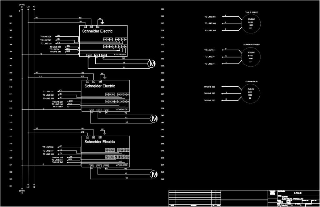
42 6.6 Motor Controls

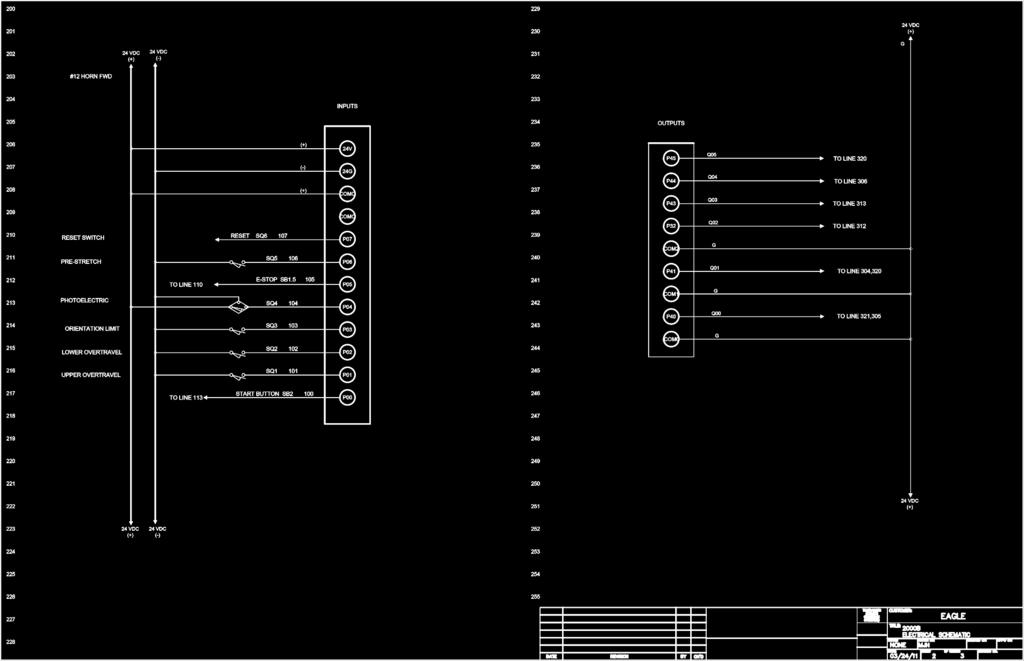
43 6.6 PLC Wiring
44 6.6 Optional Scale


45 6.6 Switches & Relays
Operations Manual Eagle 1000 Series Stretch Wrapper
 Operations Manual Eagle 1000 Series Stretch Wrapper Models A & B - 1 - READ ALL INSTRUCTIONS CONTAINED IN THIS MANUAL PRIOR TO MACHINE INSTALLATION! - 2 - Contents page 1. Machine Safety Information 1.1
READ ALL INSTRUCTIONS CONTAINED IN THIS
 Operations Manual Eagle R2B2 Stretch Wrapper READ ALL INSTRUCTIONS CONTAINED IN THIS MANUAL PRIOR TO MACHINE INSTALLATION! - 1 - Contents page 1. General Information 1.1 Installation Notes 2 1.2 Operational
GENERAL INFORMATION. H-1649, H-1650, H-1651 H-1653, H-1654 Easy-Count. uline.com. that may hurt accuracy:
 π H-1649, H-1650, H-1651 H-1653, H-1654 Easy-Count counting scale 1-800-295-5510 uline.com 1-800-295-5510 GENERAL INFORMATION Avoid placing the scale in locations that may hurt accuracy: 1. Temperature
2013 Elite T4000 (TM461C) Service Manual
 Service Manual") 2013 Elite T4000 (TM461C) Service Manual 1 TABLE OF CONTENTS CHAPTER 1: SERIAL NUMBER LOCATION...3 CHAPTER 2: PREVENTATIVE MAINTENANCE 2.1 Preventative Maintenance. 4 2.2 Tension and Centering the Running
2013 Elite T4000 (TM461C) Service Manual 1 TABLE OF CONTENTS CHAPTER 1: SERIAL NUMBER LOCATION...3 CHAPTER 2: PREVENTATIVE MAINTENANCE 2.1 Preventative Maintenance. 4 2.2 Tension and Centering the Running
SAFE AND SECURE EXTREME R MOTOR OWNER'S MANUAL MODEL PRO-FDG FOR TECHNICAL SUPPORT PLEASE CALL 1-(855) OPERATOR SERIAL#
 OPERATOR SERIAL#") SAFE AND SECURE EXTREME R MOTOR OWNER'S MANUAL MODEL PRO-FDG FOR TECHNICAL SUPPORT PLEASE CALL 1-(855) 594-4969 3121B(4) ECN 1288 BY TG 2/6/15 OPERATOR SERIAL# PRO-FDG MOTOR OPERATORS MOTOR OWNER'S MANUAL
SAFE AND SECURE EXTREME R MOTOR OWNER'S MANUAL MODEL PRO-FDG FOR TECHNICAL SUPPORT PLEASE CALL 1-(855) 594-4969 3121B(4) ECN 1288 BY TG 2/6/15 OPERATOR SERIAL# PRO-FDG MOTOR OPERATORS MOTOR OWNER'S MANUAL
LS8.0T Service Manual
 LS8.0T Service Manual 1 TABLE OF CONTENTS CHAPTER 1: SERIAL NUMBER LOCATION...3 CHAPTER 2: PREVENTATIVE MAINTENANCE 2.1 Preventative Maintenance. 4 2.2 Tension and Centering the Running Belt....6 CHAPTER
SERVICE MANUAL (DOMESTIC & INTERNATIONAL)
") SERVICE MANUAL (DOMESTIC & INTERNATIONAL) DUAL TECHNOLOGY FINISHER MODEL 1960 & 1980 SERIES Lincoln Foodservice Products, LLC 1111 North Hadley Road Fort Wayne, Indiana 46804 United States of America Telephone:
SERVICE MANUAL (DOMESTIC & INTERNATIONAL) DUAL TECHNOLOGY FINISHER MODEL 1960 & 1980 SERIES Lincoln Foodservice Products, LLC 1111 North Hadley Road Fort Wayne, Indiana 46804 United States of America Telephone:
Thunder Power Tarp Kit Operation. Dual Arm Curb Side Stowing Single Arm Curb Side Stowing Flex Arm Curb Side Stowing.
 Thunder Power Tarp Kit Operation Dual Arm Curb Side Stowing Single Arm Curb Side Stowing Flex Arm Curb Side Stowing 011-52475 Rev - 2 P a g e USE THE PROCEDURES BELOW TO OPERATE THE TARP SYSTEM Powering
Kalamazoo Packaging Systems. Division of Kal-Tek, Inc. SEMI-AUTOMATIC STRETCH WRAP SYSTEM OPERATOR S MANUAL 02/01//05
 Kalamazoo Packaging Systems Division of Kal-Tek, Inc. MODEL 4000M-SA SEMI-AUTOMATIC STRETCH WRAP SYSTEM OPERATOR S MANUAL 02/0//05 Table of Contents Warranty...... 3 Assembly... 3 Set up... 4 Film loading
EXTREME R MOTOR OWNER'S MANUAL
 EXTREME R MOTOR OWNER'S MANUAL 2 HP, 3 HP & 5 HP WITH SELF-ENGAGING CHAIN HOIST FOR TECHNICAL SUPPORT PLEASE CALL 1-(855) 594-4969 3137B(0) ECN 1313 BY JM 7/9/15 OPERATOR SERIAL# PRO-FDG MOTOR OPERATORS
uline.com
 π H-1679 H-2331 PALLET TRUCK SCALE 1-800-295-5510 uline.com Avoid placing the scale in locations that may AFFECT accuracy: 1. Temperature extremes Do not place in direct sunlight or near air conditioning
TC1000 Service Manual SALES: CUSTOMER SERVICE:
 TC1000 Service Manual SALES: 800-278-3933 CUSTOMER SERVICE: 800-745-1373 Table of Contents Section Page I. Overview 2 II. Troubleshooting Tables 3 III. Maintenance Procedures Procedure 1 Removal and Reinstallation
Table of Contents. Timer Identification Timer ID BLU-U Features: 1K 6K BLU-U Features 1K 6K
 DUSA Pharmaceuticals, Inc. Table of Contents Go to Chart # Timer Identification Timer ID BLU-U Features: 1K 6K BLU-U Features 1K 6K BLU-U Features: 10K BLU-U Features 10K BLU-U Symptom Fans Running, Timer
INSTALLATION INSTRUCTIONS FOR DSP9600/9100 WHEEL BALANCER
 Form 5063T, 06-05 Supersedes Form 5063T, 02-04 INSTALLATION INSTRUCTIONS FOR DSP9600/9100 WHEEL BALANCER This document provides the information needed to install the DSP9600/9100 Wheel Balancer. NOTE:
PRODUCT INFORMATION BULLETIN #3365 DIGITAL MOTOR CONTROL PLATTER SYSTEMS For Serial Number and After
 PRODUCT INFORMATION BULLETIN #3365 DIGITAL MOTOR CONTROL PLATTER SYSTEMS For Serial Number 28640996 and After Record Platter System Identification Numbers Here: Model # Serial # Table of Contents Program
LS10.0T Service Manual
 LS10.0T Service Manual 1 TABLE OF CONTENTS CHAPTER 1: SERIAL NUMBER LOCATION...3 CHAPTER 2: PREVENTATIVE MAINTENANCE 2.1 Preventative Maintenance. 4 2.2 Tension and Centering the Running Belt....6 CHAPTER
Marsh Shipping Supply Co. LLC. Marsh TD2100 Electric Taper Technical Manual
 Marsh Shipping Supply Co. LLC Marsh TD2100 Electric Taper Technical Manual 2 A wall-socket must be close to the product and readily accessible. The overall system is protected against overload by the branch
Battery Management Innovation. For 12-volt automotive starting batteries and starting/charging systems INSTRUCTION MANUAL
 Battery Management Innovation For 12-volt automotive starting batteries and starting/charging systems INSTRUCTION MANUAL ! CAUTION Because of the possibility of personal injury, always use extreme caution
OEM TM-50 Quick Start Guide
 This quick start guide provides basic setup and operating instructions for the OEM TM-50. The intended use of the OEM TM-50 Taping Machine is to produce taped reels of individually sealed and consistently
XPS-ProFeed Shuttle SERVICE MANUAL. Revised:
 XPS-ProFeed Shuttle SERVICE MANUAL Revised: 9-14-15 RENA SYSTEMS INC. 910 East Main Street; Suite 200 Norristown, PA 19401-4110 Phone: (610) 650-9170 Fax: (610) 270-3947 Web Site: www.renausa.com SAFETY
SB 2000 PUSH TO SEARCH NEXT STAG E. Aerotech, Inc. FORM: QM 1320
 Inlet Controller SB 2000 USER'S MANUAL AUTO OPEN MANUAL PUSH TO SEARCH NEXT STAG E CLOSE Aerotech, Inc. FORM: QM 1320 4215 Legion Dr. Mason, MI 48854-1036 USA Rev. 3, Sept. 1997 Ph. (517) 676-7070 Fax
JEEVES. JEEVES Installation Manual. Installation Manual The Easiest Do-It-Yourself Dumbwaiter on the Market
 1 888-323-8755 www.nwlifts.com JEEVES Installation Manual The Easiest Do-It-Yourself Dumbwaiter on the Market This manual will cover the installation procedure step-by-step. The installation of this dumbwaiter
1 2 3a 3b THREADING CARD 9 10 ABC Office
 1 2 3a 3b 4 5 6 7 8 9 10 THREADING CARD Important Safety instructions YOUR SAFETY AS WELL AS THE SAFETY OF OTHERS IS IMPORTANT TO GBC. IN THIS INSTRUCTION MANUAL AND ON THE PRODUCT ARE IMPORTANT SAFETY
GENERAL INFORMATION AVOID PLACING THE SCALE IN LOCATIONS THAT MAY AFFECT ACCURACY:
 π H-4564 PALLET TRUCK SCALE WITH PRINTER 1-800-295-5510 uline.com AVOID PLACING THE SCALE IN LOCATIONS THAT MAY AFFECT ACCURACY: 1. Temperature extremes Do not place in direct sunlight or near air conditioning
Reliant Series Floor Scale
 Installation Manual Reliant Series Floor Scale Model: 3300 2005 by Fairbanks Scales. All rights reserved 50783 Issue 2 10/06 Amendment Record Reliant Series Floor Scale Model: 3300 50783 Manufactured by
SX1000 Service Manual SALES: CUSTOMER SERVICE:
 SX1000 Service Manual SALES: 800-278-3933 CUSTOMER SERVICE: 800-745-1373 Revision: August 1999 Table of Contents Section Page I. Overview 2 II. Troubleshooting Tables 3 III. Maintenance Procedures Procedure
Reproduction or other use of this Manual, without the express written consent of Vulcan, is prohibited.
 SERVICE MANUAL ELECTRIC BRAISING PANS (30 & 40 GALLON) VE30 VE40 ML-126849 ML-126850 VE40 SHOWN - NOTICE - This Manual is prepared for the use of trained Vulcan Service Technicians and should not be used
XPS-ProFeed Shuttle SERVICE MANUAL. Revised:
 XPS-ProFeed Shuttle SERVICE MANUAL Revised: 1-14-15 RENA SYSTEMS INC. 910 East Main Street; Suite 200 Norristown, PA 19401-4110 Phone: (610) 650-9170 Fax: (610) 270-3947 Web Site: www.renausa.com SAFETY
Installation & Calibration
 Installation & Calibration ED2-AT Series SkidWeigh System Lift Truck On-board Check Weighing With Accumulative Load Weight Total ED2-AT Series SkidWeigh V.1.1 General Installation Guide This ED2-AT Series
The RCS-6V kit. Page of Contents. 1. This Book 1.1. Warning & safety What can I do with the RCS-kit? Tips 3
 The RCS-6V kit Page of Contents Page 1. This Book 1.1. Warning & safety 3 1.2. What can I do with the RCS-kit? 3 1.3. Tips 3 2. The principle of the system 2.1. How the load measurement system works 5
Automatic Sliding Door Retrofit Drive Assembly. Installation Manual DoorControlsUSA.com
 Automatic Sliding Door Retrofit Drive Assembly Installation Manual 800-437-3667 DoorControlsUSA.com TABLE OF CONTENTS pg. 1. COMPONENTS 2 2. HEADER PREPARATION 2 3. DOOR PREPARATION 2 4. MOTOR AND CONTROLLER
Service Manual. For the SCV2832E, SCV2426, Automatic Scrubbers For: Training Troubleshooting
 Service Manual For the SCV2832E, SCV2426, SCV280000 & ES2832 Automatic Scrubbers For: Training Troubleshooting Adjustments Contents 1 Cautions ----------------------------------------------------------------------
SOLAR LIGHTING CONTROLLER SUNLIGHT MODELS INCLUDED IN THIS MANUAL SL-10 SL-10-24V SL-20 SL-20-24V
 SOLAR LIGHTING CONTROLLER OPERATOR S MANUAL SUNLIGHT MODELS INCLUDED IN THIS MANUAL SL-10 SL-10-24V SL-20 SL-20-24V 10A / 12V 10A / 24V 20A / 12V 20A / 24V 1098 Washington Crossing Road Washington Crossing,
ONE TOUCH CONTROL BOX
 ONE TOUCH CONTROL BOX CONVERSION KIT INSTRUCTIONS REMOVAL, INSTALLATION, OPERATION, AND REMOTE CONTROL PROGRAMMING THUNDERSTONE PART #101322 REVISION A JULY 14 TH 2016 2 P a g e INSTALLING THE THUNDER
Installation Manual. AutoSteer. Gleaner Combine. AutoGuide 2 Steer Ready. Supported Models A66 A76 R66 R76 S67 S77 PN: A
 Installation Manual AutoSteer Gleaner Combine AutoGuide 2 Steer Ready Supported Models A66 A76 R66 R76 S67 S77 PN: 602-0312-01-A LEGAL DISCLAIMER Note: Read and follow ALL Instructions in this manual carefully
Thunder Power Tarp Kit Operation
 Thunder Power Tarp Kit Operation Dual Arm Curb Side Stowing Single Arm Curb Side Stowing 011-52476 Rev. H P a g e 2 In this booklet you will find: OPERATING INSTRUCTIONS... 3 Powering up or down the system...
Operator s Manual. Fairbanks FH Series by Fairbanks Scales, Inc. All rights reserved. . Revision 1 06/2017
 Operator s Manual Fairbanks FH Series 2017 by Fairbanks Scales, Inc. All rights reserved 51393. Revision 1 06/2017 Amendment Record Fairbanks FH Series Operator s Manual Operator s Manual Document 51393
FD 120 Card Cutter MAINTENANCE MANUAL. MyBinding.com 5500 NE Moore Court Hillsboro, OR Toll Free: Local: /2011
 FD 120 Card Cutter 5/2011 MAINTENANCE MANUAL SAFETY PRECAUTIONS Always observe the cautions and warnings given below to prevent personal injury or property damage. The degree of danger and damage that
ECHO Enhanced Controller Hook Count Application *** Infrared Photo Sensors *** GCA 110 ECHO Controller. Version 3.5
 ECHO Enhanced Controller Hook Count Application *** Infrared Photo Sensors *** GCA 110 ECHO Controller Version 3.5 1 Change History: Feb 01, 2005 Mar 16, 2005 May 22, 2005 May 9, 2006 By request from CCS,
ISO1000R Service Manual SALES: CUSTOMER SERVICE:
 ISO1000R Service Manual SALES: 800-278-3933 CUSTOMER SERVICE: 800-745-1373 Revision: August 1999 Table of Contents Section Page I. Overview 2 II. Troubleshooting Tables 3 III. Maintenance Procedures Procedure
MDX-300 Series. For 12-volt automotive starting batteries and starting/charging systems INSTRUCTION MANUAL
 For 12-volt automotive starting batteries and starting/charging systems INSTRUCTION MANUAL Blank page Contents Caution... 4 Capabilities... 4 Display and Keypad... 4 Preparations Before the Test... 6 Connecting
Altec LMAP. (Load Moment and Area Protection) Telescopic Boom Cranes. Calibration
 Telescopic Boom Cranes. Calibration") Altec LMAP (Load Moment and Area Protection) Telescopic Boom Cranes Calibration Contents System Components...1 Anti-Two Block...1 Area Alarm...1 Boom Angle Sensor...1 Display...1 Extension Sensor...2 Function
Altec LMAP (Load Moment and Area Protection) Telescopic Boom Cranes Calibration Contents System Components...1 Anti-Two Block...1 Area Alarm...1 Boom Angle Sensor...1 Display...1 Extension Sensor...2 Function
POWERED MANUAL STRETCH WRAP SYSTEM OPERATORS MANUAL
 MODEL 4000M-PM w/ SCALE MODEL 4000T-PM w/o SCALE POWERED MANUAL STRETCH WRAP SYSTEM OPERATORS MANUAL M-4000M-PM-12 1 Table of Contents Introduction 3 Warranty 3 Modular Design 3 Assembly 4 Set-up 4 Film
TROUBLESHOOTING. Ecomat EASY / Girotec WRS Ecomat EASY H / Girotec WRS H V2.0
 TROUBLESHOOTING This manual is for helping you through the possible malfunction solving process. Because most common cause of troubles are wrong kind of machine settings, in chapter one we shortly go trough
Centrifuge Operator / Service Manual
 3000 Centrifuge Centrifuge Operator / Service Manual cat.# 26230 & 26231 The Q-sep 3000 centrifuge complies with all requirements of UL standard 3101 20, Can/CSA C22.2 No. 1010.1, and Can/CSA C22.2 No.
MAGPOWR Spyder-Plus-S1 Tension Control
 MAGPOWR TENSION CONTROL MAGPOWR Spyder-Plus-S1 Tension Control Instruction Manual Figure 1 EN MI 850A351 1 A COPYRIGHT All of the information herein is the exclusive proprietary property of Maxcess International,
TABLE OF CONTENTS CHAPTER 1.. CHAPTER 2.. CHAPTER 3.. CHAPTER 4.. CHAPTER 5.. CHAPTER 6.. CHAPTER 7.. CHAPTER 8.. CHAPTER 9..
 CHAPTER 1.. CHAPTER 2.. CHAPTER 3.. CHAPTER 4.. CHAPTER 5.. CHAPTER 6.. CHAPTER 7.. CHAPTER 8.. CHAPTER 9.. CHAPTER 10... CHAPTER 11... CHAPTER 12... TABLE OF CONTENTS SPECIFICATIONS:...1 PRECAUTIONS:...2
COOKSON OWNER'S MANUAL
 COOKSON OWNER'S MANUAL FDO-A10 INDUSTRIAL DUTY FIRE DOOR OPERATOR R L I S T E D 3040233 US CONTROL PANEL SERIAL# OPERATOR SERIAL# 9001.DWG ECN 0959 REV 4 SPECIFICATIONS MOTOR TYPE:...INTERMITTENT HORSEPOWER:...1/8
EB Conveyor Maintenance Guide
 EB Conveyor Maintenance Guide EN-0037 Rev A EB Conveyor Maintenance Guide www.qdraw.com Table of Contents Overview Page 3 Exploded View Of A Standard EB Conveyor Page 4 Preventative Maintenance Page 5
A Flex Low Profile Automatic Performance Features
 LP A Flex A models eliminate the need for operators to attach and cut the stretch film. Simply place the pallet load on the machine, and pull a lanyard switch while backing away. The machine will perform
Prusa i3 Printer Assembly Guide
 Prusa i3 Printer Assembly Guide Special thanks to Carlos Sanchez and Miguel Sanchez for the graphics. All graphics captured from their great animation: http://www.carlos-sanchez.com/ Prusa3/ For copyright
Service Instructions. Centurion Qex CeramPress Qex Neytech Qex. DENTSPLY Ceramco Yucaipa, CA
 Service Instructions Centurion Qex CeramPress Qex Neytech Qex DENTSPLY Ceramco Yucaipa, CA Table of Content Chapter Title 1 General Information 1.1 Safety Information 1.2 Repair Devices and Tools 2 Repair
T & T Service Manual
 T101-04 & T202-03 Service Manual 1 2 3 Contents CHAPTER 1: SERIAL NUMBER LOCATION... 6 CHAPTER 2: PREVENTATIVE MAINTENANCE 2.1 Preventative Maintenance... 8 2.2 Tension and Centering the Running Belt...
To Purchase This Item, Visit BMI Gaming
 Table of Contents General Operation. 3 How Slam-A-Winner plays How the Wheel Scores How the Ball Lift works Programming Options... 4-6 Troubleshooting Guide. 7-8 Parts Identification 9 Schematics 10-13
AXLE MOUNT MODELS: FILM ROLLER MODELS: OPERATING & SERVICE PARTS MANUAL TABLE TOP OVERWRAPPERS MODEL 625A MODEL 625A MINI MODEL 825A MODEL 875A
 OPERATING & SERVICE PARTS MANUAL TABLE TOP OVERWRAPPERS Model 625A AXLE MOUNT MODELS: MODEL 625A SINGLE ROLL WITH MOUNTING AXLES MODEL 625A MINI COMPACT SINGLE ROLL WITH MOUNTING AXLES MODEL 825A DUAL
Pallet Truck with Scale Instruction Manual
 Pallet Truck with Scale Instruction Manual 11 Harbor Park Drive Port Washington, NY 11050 Table of Contents General Specifications.............................3 Maintenance......................................4
FR FROMM ROBOT SERIES 2011 Self-propelled machines for wrapping stacked loads with protective LLDPE film.
 Page: 1/12 FROMM Half Automatic ROBOT Stretch wrapping machine, FR FROMM ROBOT SERIES 2011 Self-propelled machines for wrapping stacked loads with protective LLDPE film. FR33x Series; With MECHANICAL TENSION
Intelligent torque meter tester
 Intelligent torque meter tester Before using this product, please read the instructions carefully, which will help improve the efficiency of your use of this product Contents 一 About HP Series Torque Meter...2
Heated Bed Installation Instructions
 Heated Bed Installation Instructions Overview The glass panel is heated by way of a heater element which is bonded to the glass panel and controlled by a digital temperature controller. The temperature
Induction Power Supplies
 Induction Power Supplies 7.5kW; 135 400kHz 480V version (Integral Heat Station) User s Guide Model 7.5-135/400-3-480 SMD Control Brds Rev. D 5/08 Table of Contents 1. Specifications and features...3 2.
Read these instructions thoroughly before attempting to install this option.
 Rewind Option Kit Installation Instructions This kit includes the parts and documentation necessary to install the Media Rewind option into the following printers: 0XiIIIPlus, 0 dpi 0XiIIIPlus, 00 dpi
OPERATING & SERVICE PARTS MANUAL SM20ES ENERGY SMART WRAPPER
 OPERATING & SERVICE PARTS MANUAL SM20ES ENERGY SMART WRAPPER Series B Model SM20ESC6 Cradle Mount Model SM20ESC6 Cradle Mount Shown with Optional Left & Right Wings Model SM20ESC6 Cradle Mount Shown with
Installation and Service Manual
 RESIDENTIAL PLATFORM LIFTS RPL400 / RPL600 Installation and Service Manual WARNING! STRICT ADHERENCE TO THESE INSTALLATION INSTRUCTIONS IS REQUIRED to promote the safety of those installing this product,
LP & HP Series Turntable Stretch Wrapping Systems
 LP & HP Series Turntable Stretch Wrapping Systems Flex turntable stretch wrappers are available in three configurations so you can be sure to find the right machine for your application. Automatic Flex
INSTRUCTION MANUAL ALL TERRAIN PALLET TRUCK HAND PALLET TRUCK
 INSTRUCTION MANUAL ALL TERRAIN PALLET TRUCK HAND PALLET TRUCK WARNING! 1. Read and understand instruction manual before using the pallet truck. 2. Do not place hands or feet under the pallet truck at any
Procedure Replacing a Cover
 Procedure 7.1 - Replacing a Cover Cover Removal 1. Remove two screws, one each side, from the front of the top cover. Remove the top cover. See Diagram 7.1. Diagram 7.1 - RBK 815 Covers Top Cover Left
INSTALLATION and OPERATION BALL WASHER MODEL NO: BW-001N
 Easy Picker Golf Products, Inc. 415 Leonard Blvd. N., Lehigh Acres, FL 33971 PH: 239-368-6600 FAX: 239-369-1579 Service: 800-982-4653 SALES: 800-641-4653 www.easypicker.com salesdept@easypicker.com INSTALLATION
Kalamazoo Packaging Systems
 Kalamazoo Packaging Systems Division of Kal-Tek, Inc. MODEL# 939-M36 115 Volt WINDOW/PANEL STRETCH WRAP SYSTEM OPERATOR S MANUAL 1 Table of Contents Introduction...3 Warranty 3 Wrapping Operation 4 Description
9.17, 9.17si Treadmill
 9.17, 917si Treadmill 9.17, 9.17si Treadmill Warning: This service manual is for use by Precor trained service providers only. If you are not a Precor Trained Servicer, you must not attempt to service
Hand Held Pull Tester Instruction Manual Order No
 Instruction Manual Order No. 63801-9700 Doc. No: TM-638019700 Release Date: 02-21-12 UNCONTROLLED COPY Page 1 of 13 Safety Warnings and Information Read and understand all of the instructions and safety
Cutler-Hammer. Instructions for Installation, Operation, and Maintenance of the AMPGARD Reduced Voltage Soft Starter
 Operation, and Maintenance of the Instruction Bulletin Read and understand these instructions before attempting any installation, operation, or maintenance of the. This equipment shall be installed and
Auto Sentry-eXP Maintenance. Revised 12/21/07
 Auto Sentry-eXP Maintenance Revised 12/21/07 Maintenance Procedures for Auto Sentry exp Bill Dispenser Credit Card Reader Bill Acceptor Bill Dispenser Maintenance Bill Dispenser Problem / Cause Bill Dispenser
GPS AutoSteer System Installation Manual
 GPS AutoSteer System Installation Manual Supported Vehicles Case IH Vehicles Case 2577 Combines Case 2588 Combines Accuguide Ready PN: 602-0233-01-A LEGAL DISCLAIMER Note: Read and follow ALL instructions
TERMINATOR User Manual
 TERMINATOR User Manual TERMINATOR User Manual Table of Contents Section Page 1 2 3 4 5 6 7 8 9 10 11 12 13 14 15 16 17 18 19 20 21 Introduction Safety Precautions Features and Benefits Overview of the
348002K/348012K Manifold Block Style Service Manual 12/2000
 348002K/348012K Manifold Block Style Service Manual 12/2000 Service Manual 348002K/348012K Manifold Block Style Recovery/Recycling/Recharging Unit For R-12 or R-134a Only TABLE OF CONTENTS: Theory of Operation
Customer Name: Serial Number: Y-Axis Stall
 Technician Name: Date: Technician Name: Date: Customer Name: Serial Number: Y-Axis Stall Issue Explanation and Background Each drive motor on the machine (the x, y and z axes motors) has a sensor called
RD712 & RD712XL Remote Displays. Model 615 / 615XL Indicator User s Manual
 RD712 & RD712XL Remote Displays Model 615 / 615XL Indicator User s Manual EUROPEAN COUNTRIES WARNING This is a Class A product. In a domestic environment this product may cause radio interference in which
ADHESION/RELEASE TESTER
 ADHESION/RELEASE TESTER MODEL AR-2000 OPERATING INSTRUCTIONS CHEMINSTRUMENTS 510 COMMERCIAL DRIVE FAIRFIELD, OHIO 45014 (513) 860-1598 www.cheminstruments.com Revision 1.0 December 13, 2016 CONTENTS PRODUCT
MA Series rotary tower automatic Stretch Wrapping Systems
 MA Series rotary tower automatic Stretch Wrapping Systems The MA-X is Orion s flagship automatic. The MA-X offers customers the highest speeds and most robust frame design for years of reliable and economical
Installation Instructions Table of Contents
 Installation Instructions Table of Contents Pre- Installation of Garage Storage Lift 2 Layout the Garage Storage Lift 3 Installing the strut Channels 3 Install the Drive Assembly 5 Install the Drive Shaft
GARAGE DOOR OPERATOR USER S MANUAL
 GARAGE DOOR OPERATOR USER S MANUAL - DOMESTIC USE CIL-CD800S Chain) CIL-BD800S Belt GARAGE DOOR OPENER OWNER S MANUAL - DOMESTIC USE CIL-CD800S CD800S(Chain Chain) CIL-BD800S BD800S(Belt Belt) 1 Features
MAINTENANCE INSTRUCTIONS
 MAINTENANCE INSTRUCTIONS ECOMAT EASY / GIROTEC WRS Version G0101 ECOMAT EASY H / GIROTEC WRS H Version G0301 ECOMAT PLUS / ECOMAT PLUS H Versions G0503 / G0603 V 2.0 Table of contents 1/3 1.0 Maintenance
WARNING: ALWAYS UNPLUG THE TREADMILL FROM THE ELECTRICAL OUTLET BEFORE SERVICING THE UNIT.
 Z100-A81 CE Treadmill WARNING: ALWAYS UNPLUG THE TREADMILL FROM THE ELECTRICAL OUTLET BEFORE SERVICING THE UNIT. Table of Contents TABLE OF CONTENTS Table of Contents...1 Table of Figures...3 Description...4
CALIBRATION PROCEDURE FOR THE ALLEN-BRADLEY PLC TEMPERATURE CONTROLLER:
 CALIBRATION PROCEDURE FOR THE ALLEN-BRADLEY PLC TEMPERATURE CONTROLLER: Note: The following procedure utilizes an Omega Model CL23A Digital Calibrator/Thermometer. If an equivalent calibrator/thermometer
OLYMPIAN MODEL 740 Operation and Service Manual
 OLYMPIAN MODEL 740 Operation and Service Manual P/N 133911-102 FCI MANUAL P/N 133865-001 Data herein has been verified and validated and believed adequate for the intended use. If the machine or procedures
Thunder Power Tarp Kit Operation Guide
 Thunder Power Tarp Kit Operation Guide Dual Arm Curb Side Stowing Single Arm Curb Side Stowing Flex Arm Curb Side Stowing REV - B 1/13/17 2 P a g e USE THE PROCEDURES BELOW TO OPERATE THE TARP SYSTEM Powering
Price Computing Scale D Series Operation Manual
 This Document is Hosted by: www.oldwillknottscales.com Price Computing Scale D Series Operation Manual Cardinal Scale Manufacturing Co. 8529-M400-O1 Rev. A PO BOX 151 WEBB CITY, MO 64870 04/13 PH (417)
RETROFIT INSTALLATION
 RETROFIT INSTALLATION Installation Instructions C0013536 Pallet Grip Q Series Semi-Automatic Machines Manufacture Date before July, 2010 1 RETROFIT INSTALLATION Table of Contents 1.0 Introduction... 3
INSTALLATION MANUAL SPECTRUM BRAKE CONTROL
 INSTALLATION MANUAL 51170 SPECTRUM BRAKE CONTROL TABLE OF CONTENTS Controls & Components Tools List Before You Begin Wiring Wiring Diagram Mounting the LED Display Rotary Knob Wiring the Plug Connector
5000TOC Sensor Service Manual
 Part No. 84449 5000TOC Sensor Service Manual This document contains proprietary information, which is protected by copyright. All rights are reserved. No part of this document may be photocopied (other
* * APPLICABLE MODELS: 2014 > Mazda 3
 PART NUMBER: 0000 8C L48 (DIO) / 0000 89 L84 (PIO) GENUINE ACCESSORIES INSTALLATION INSTRUCTIONS Rev. AAA *550-0700-000* APPLICABLE MODELS: 2014 > Mazda 3 REQUIRED COMPONENTS: ITEM QTY DESCRIPTION Usage
Maintenance and Lubrication
 Maintenance and Lubrication Proper maintenance is necessary to ensure safe, trouble free operation. Inspecting the lift for any wear, damage or other abnormal conditions should be a part of the transit
Overload Warning System DS 50
 Overload Warning System DS 50 Grove - FMTV Trouble Shooting Manual Level 1 - Basics - 1 Table of contents Troubleshooting Manual PAT Overload Warning system DS 50 Level 1 -Basics- Item Content Page 1.
Vertical Toaster Idler Installation Kit
 826-1666 Vertical Toaster Idler Installation Kit Follow these instructions to install the springloaded idler and new chain on the McDonald s Vertical Toaster. Use the attached check list to ensure all
Addendum to VT Tensioner Kit Instructions
 Addendum to VT Tensioner Kit Instructions 819-5800 Approximately 75 Vertical Toasters manufactured between May 2000 and September 2000 require a modified sprocket mounting bracket for proper spring tension.
CAMSHAFT TIMING CHAIN, SPROCKET, AND TENSIONER REPLACEMENT
 Page 1 of 45 CAMSHAFT TIMING CHAIN, SPROCKET, AND TENSIONER REPLACEMENT Special Tools J 45027 Tensioner Tool J 45059 Angle Meter Page 2 of 45 Removal Procedure Page 3 of 45 Page 4 of 45 Page 5 of 45 Fig.
CABINET REEL OPERATING INSTRUCTIONS
 CABINET REEL OPERATING INSTRUCTIONS MODELS 15, 25, 40 & 60 SERIES RAPID-AIR CORPORATION 4601 KISHWAUKEE ST. ROCKFORD, IL 61109-2925 Phone: (815) 397-2578 Fax: (815) 398-3887 Web Site: www.rapidair.com
750 Series Press Conveyor Installation and Maintenance Manual
 750 Series Press Conveyor Installation and Maintenance Manual Metzgar Conveyor Co. - 2010 METZGAR CONVEYORS SAFETY PRECAUTIONS WARNING: DO NOT ATTEMPT MAINTENANCE ON ANY CONVEYORS WHILE IN OPERATION. BEFORE
Inlet Controller TC5-ITA USER'S MANUAL. M rev. 02 K rev. 00
 Inlet Controller TC5-ITA USER'S MANUAL M 890-00047 rev. 02 K 895-00458 rev. 00 TABLE OF CONTENTS PRECAUTIONS... 3 FEATURES... 4 LOCATION OF THE CONTROLS... 5 Status Leds...5 Internal Switches...6 INSTALLATION
Kalamazoo Packaging Systems. Division of Kal-Tek, Inc. MODEL 6006H-M S A SEMI-AUTOMATIC STRETCH WRAP SYSTEM OPERATOR S MANUAL 02/01//05
 Kalamazoo Packaging Systems Division of Kal-Tek, Inc. MODEL 6006H-M S A SEMI-AUTOMATIC STRETCH WRAP SYSTEM OPERATOR S MANUAL 02/01//05 1 Table of Contents Warranty...... 3 Assembly... 3 Set up... 4 Film