Altec LMAP. (Load Moment and Area Protection) Telescopic Boom Cranes. Calibration
|
|
|
- Logan Lucas
- 5 years ago
- Views:
Transcription


1 Altec LMAP (Load Moment and Area Protection) Telescopic Boom Cranes Calibration
2 Contents System Components...1 Anti-Two Block...1 Area Alarm...1 Boom Angle Sensor...1 Display...1 Extension Sensor...2 Function Kick-Out...2 Pressure Transducers...2 Operator Alarms...2 LMAP Display...3 Calibration...5 Entering Calibration Mode...6 Extension Sensor Setup...7 Checking the Angle Sensor Voltage...8 Angle Sensor Setup (Physical Zero)...9 Spanning Extension and Angle Sensors Zeroing the Swing Potentiometer Disabling the Swing Pot Enabling the Swing Potentiometer... RCI-510 i
3 RCI-510 ii
4 Introduction System Components LMAP Display Unit LMAP Computer Unit Pressure Transducers Extension Reel with length and angle sensors Anti Two-Block (ATB) switches Cables The Load Moment Area Protection (LMAP) system is intended to aid the crane operator by continuously monitoring the load and warning of an approach to an overload or two-block condition. Crane functions are monitored by means of high accuracy sensors. The system continuously compares the load suspended below the boom head with the crane capacity chart stored in the computer memory. At approach to overload, the system warns by means of audible and visual alarms. The system can be configured to cause function kick-out by sending a signal to function disconnect solenoids. Anti Two Block (ATB) A switch monitors the approach of the hookblock or overhaul ball to the boom head. The switch is held in the normal position until the hookblock or overhaul ball raises a weight that is mounted around the hoist rope. When the weight is raised, it causes the switch to operate. The resultant signal is sent to the computer via the extension reel causing the ATB alarm to operate and function kick-out to occur. Area Alarm When set, this alarm permits the operator to define the operating zone by only two set points. The use of this method of setting results in a greatly enhanced working area, and also clearly defines the operating zone. Boom Angle Sensor Boom angle is measured by means of a high accuracy potentiometer, a magnetically dampened pendulum to prevent erratic voltage changes. It provides a voltage proportional to boom angle. The boom angle sensor is mounted inside the cable extension reel assembly. Display The operator is provided with a continuous display of: Rated Load Actual Load Bar Graph showing Percentage of Rated Load Radius of the Load Boom Angle Main Boom Length Working Area Crane Configuration On-screen messages provide the operator with visual warnings of conditions that occur during operation of the system. 1
5 Extension Sensor The extension sensor provides an increasing voltage proportional to the extension of the boom. A cable attached to the boom head provides a low current electrical path for the ATB signal. Function Kick-Out Electrically operated solenoids disconnect the control lever functions for boom hoist lower, telescope out, and winch up whenever an overload or an ATB condition occurs. Pressure Transducers Two pressure transducers measure the pressure in the boom hoist cylinder. The resultant Total Moment signal is processed to provide a continuous display of the load suspended below the point of lift. Operator Alarms These alarms, when properly set by the operator, define the operating range. This is achieved by means of minimum and maximum angle, maximum height, and/or maximum length. These alarms can be programmed for each job site and allow the operator to work in a defined area. 2
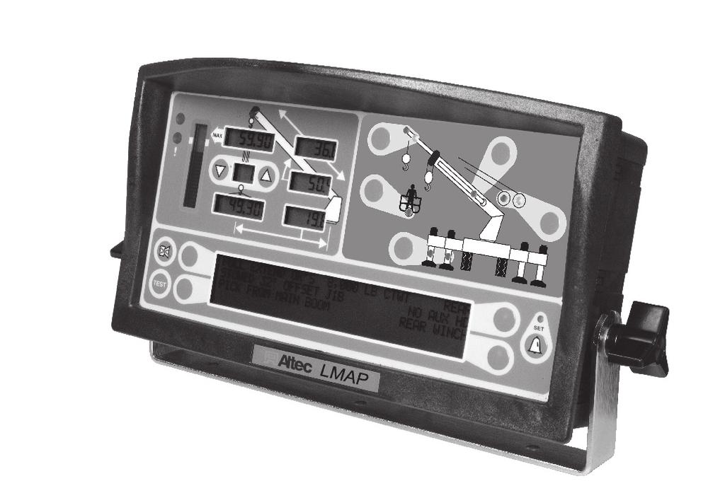
6 LMAP Display 1. Overload Warning This red LED illuminates when you reach or exceed 100% of rated capacity. It is accompanied by solid tone alarm and when maximum rated capacity is exceeded will result in boom function lockout. 2. Approaching Overload Warning This amber LED Illuminates when you reach or exceed 90% Rated Capacity. It will be accompanied by a beeping alarm. 3. Parts of Line Displays current number of parts of line in use. 4. Load on Hook Displays the entire hook load weight under the head of the boom, including cable, load block, load handling equipment, and weight of load hanging on hook. 5. Percent of Rated Capacity Meter - Shows the load as a percentage of rated capacity. As the load increases, the meter level increases to represent the percentage of the rated capacity of the crane. 6. Rated Capacity Displays the rated capacity in the current configuration based on the crane load capacity chart. 7. ATB Warning Warns of a potential two-block condition with flashing LED and audible alarm. 8. Boom Length Displays the current boom length in feet and tenths of a foot. 9. Boom Angle Displays the current boom angle in degrees and tenths of a degree. 10. Load Radius Displays the load radius from centerline of rotation. 11. Crane Setup These keys are used in the setup process to configure the LMAP system to match the current configuration of the crane. 12. Information Window Displays crane setup and calibration information as well as warning messages. 3
7 13. Erected Jib Enables the selection of the jib to be used on the boom. Selects extended or retracted jib when crane is equipped with two stage jib. 14. Basket Operation Enables the selection of the platform for man basket operation. 15. Outrigger Configuration Enables the selection between full and mid span outriggers. 16. Stowed Jib Enables the selection of the jib stowed on the boom. Also used to stow the erected jib. 17. Winch Selection Enables the selection of the winch if the crane is equipped with an optional second winch. 18. Alarm Cancel Disables audible alarm. Holding down this key overrides function kick-out. 19. Test Button Press and hold the test button to initiate a system self test and run diagnostics. 20. Operator Alarm Set Enables operator alarms. When an alarm has been set, the LED above this button will illuminate yellow. WARNING YOU MUST USE THE CRANE SETUP MODE TO CORRECTLY SET THE LMAP SYSTEM FOR PROPER OPERATION. THE LMAP SYSTEM SETUP MUST MATCH THE ACTUAL CONFIGURATION OF THE CRANE SO THAT IT WILL INDICATE THE CORRECT HOOK LOAD AND LIFTING CAPACITY OF THE CRANE. 4
8 Calibration The LMAP system contains a setup calibration mode that operates through the system display console. The setup mode provides a means of ensuring that the system sensors are correctly positioned and adjusted following system installation or parts replacement. This procedure assumes that installation of system components, cabling, and hydraulic connections have been successfully completed and checked. The setup procedure involves only the sensors mounted within the extension reel on the side of the boom. It is important that each step of this procedure is properly followed for the system to accurately provide load, rated capacity, warnings, and kick-out functions. WARNING AT ALL TIMES, OBSERVE SAFE PRACTICES. MAKE SURE THAT CRANE CAPACITY LIMITATIONS ARE UNDERSTOOD, AND THAT THE CRANE CAPACITY PLATE IS FOLLOWED. DO NOT EXCEED MANUFACTURER S SPECIFIED LIFTING LIMITATIONS. Required Tools Phillips Screwdrivers Digital Level Accurate to 0.1 at level Measuring tape (100 feet) fiber-type in tenths of feet Digital Voltmeter Crane Configuration Before starting the system setup, position the crane on firm and level ground with the outriggers properly extended and set. It is recommended that the crane be configured with no stowed or erected jib (bare boom) and reeved with a single part-of-line. Fully retract the boom and set it to zero degrees (±0.1 ) using a digital level. Remove the reeling drum cover to expose the length and angle sensors. 5
9 Entering Calibration Mode The display will step through each setup operation, as required by the user. During the setup procedure, the display console should be placed in a position that allows easy viewing while adjustments are being made within the boom extension reel, and allows for operation of the display buttons. To enter setup data it is necessary to put the system in calibration mode. Once in calibration mode, you will have five (5) seconds to enter the security key sequence. To access calibration mode: 1. Hold down the TEST and SET keys simultaneously. The audible alarm will sound and you will be prompted to enter the security key code. 2. Enter the security code in order (1, 2, 3, 4) as shown. The computer will execute a brief self test and, when finished, enter calibration mode. Checking Sensor Drive Voltage IMPORTANT! MAKE SURE TO MEASURE AND SET ALL VOLTAGES BEFORE CALIBRATING. 1. Remove the extension reel cover. 2. Using a digital voltmeter, measure the voltage between the RED (TB1-4) and BLUE (TB1-1) wires at the terminal block mounted on the sensor baseplate assembly. 3. Check that the voltage is between 4.7 and 5.3 volts. Voltages outside the range specified above will indicate a voltage supply problem, or a connection or short circuit problem. 6
10 Extension Sensor Setup The following procedures define how to reset and calibrate the extension sensor, if necessary. Before any of these procedures are used, check that the reel-off cable is layering correctly. Physical Zero It is necessary to ensure that the extension sensor potentiometer is correctly set to its minimum zero setting when the boom is fully retracted. This ensures that the sensor will correctly measure over the full telescoping range of the boom. 1. Disengage the main gear wheel connected to the extension sensor by pulling the sensor arm in the direction shown. 2. Rotate the gear clockwise until the sensor clutch drags or, if equipped with a ball denten type clutch, clicks. 3. Rotate the sensor counterclockwise exactly ½ turn and release the sensor arm to re-engage the gears on the sensor arm. 4. Rotate the gear counterclockwise about half a turn setting the voltage to 0.2 volts. Then, carefully release the sensor arm, ensuring that the voltage remains at 0.2 volts as the gears re-engage. Zero Calibration 1. Enter calibration mode (see page 2). 2. Press the key adjacent to either Menu Up or Menu Down until 02 Zero Sensors appears in the information window at the right. 3. Press the key adjacent to 02 Zero Sensors to enter the routine. 7
11 4. Press the key adjacent to Zero No. 2 = XX to zero the extension sensor. 5. Press the key adjacent to YES! Calibrate! to set the extension sensor to zero. 6. The retraced boom length should appear in the boom length window. Checking The Angle Sensor Voltage 1. Verify the reading on the digital level is zero degrees (0 ). 2. With a digital voltmeter, measure the voltage between the BLUE wire (TB1-1) and the GREEN wire (TB1-2). With the boom horizontal, the voltage should be between 0.3 and 0.5 volts. If the voltage is incorrect, refer to Angle Sensor Setup on page Still measuring the voltage at the same points, move the exposed side of the angle sensor pendulum downwards, and check that the potentiometer is operating by verifying that the voltage increases. 4. Check that the pendulum moves freely, and when released, falls smoothly back to the original zero degrees (0 ) voltage reading. 8
12 Angle Sensor Setup The following procedures define how to reset and calibrate the angle sensor, as required. Physical Zero It may be necessary to ensure that the angle sensor potentiometer is correctly set to its physical zero setting with the boom at zero degrees (0 ). This ensures that the sensor will correctly measure the full angle range of the boom. 1. Verify the reading on the digital level is zero degrees (0 ). 2. Loosen the two securing screws on either side of the sensor potentiometer just enough to allow the sensor potentiometer to be turned by hand. Do not remove the screws and do not put pressure on the terminals exiting the sensor. 3. Measuring the voltage between TB1-2 and TB1-1, carefully rotate the potentiometer until the voltage measures 0.4 volts. Rotating the sensor counterclockwise will increase the voltage. Rotating clockwise will reduce the voltage. Only fine adjustments are required. Do not touch the pendulum hanging behind the sensor assembly, as this will affect the reading. 4. Tighten the securing screws and check that the voltage remains at 0.4 volts. Zero Calibration 1. Press the key adjacent to Menu Up to zero the angle sensor (No. 3). 2. Press the key adjacent to Zero No. 3 = Press the key adjacent to YES! Calibrate! to set the angle sensor to zero. When you have finished, press the key adjacent to Exit to return to the main menu. 9
13 Spanning the Extension and Angle Sensors Press the key adjacent to either Menu Up or Menu Down until 03 Span Sensors appears in the information window at the right. WARNING SETTING SPANS ON THE CRANE WILL REQUIRE FULL EXTENSION OF THE BOOM. MAKE SURE THE CRANE IS SET UP ACCORDING TO THE MANUFACTURER S OPERATION MANUAL TO ENSURE MAXIMUM STABILITY. ALSO MAKE SURE ALL BOOM EXTENSIONS AND LOADS ARE LIFTED WITHIN THE APPROPRIATE LOAD CHARTS AND LIMITS. FAILURE TO COMPLY WITH MANUFACTURER S LIMITS MAY RESULT IN SERIOUS INJURY OR DEATH. Dimension S - This is the distance between the center of the boom pivot and the center of the sheave with the boom fully retracted. Dimension T - This is the dimension between the center of the boom pivot and the center of the sheave with the boom fully extended. The span of the boom is calculated by subtracting Dimension S from Dimension T (T - S = span). Number Entry The display does not have a numerical keypad so when numbers are required, the display will change to enable number entry. Keys B and D are used to scroll left and right. The cursor will appear as flashing < > brackets on either side of the number. Key A is used to enter the number. Key C is used to exit the number entry subroutine. As each number is selected, press key A to enter it into the system. The number will then appear in the [ ] brackets. Up to five numbers may be entered. When entering a negative value, enter the numbers and decimal first, then enter the minus sign. If you enter a number incorrectly, select the < backspace and press key A. When all digits look correct, press key C to calibrate the complete number. 10
14 Example: To enter the value -2.98, do the following: 1. Press key B or D until the number 2 is selected (indicated by flashing < > brackets) and then press key A to enter the number 2. Select the decimal. then press key A. 3. Repeat the previous steps to enter the number 9 and After the numbers are entered, press key B or D until the minus sign - is selected and then press key A. 5. If the value is correct, press key C to exit. Entering the Span Once the span has been determined: 1. Press the key adjacent to Span No. 2 = X.X. 2. Press the key adjacent to YES! Calibrate! to enter the span. 3. Use the number entry procedure on page 6 to enter the span. 4. With the digital level still attached to the boom, raise the boom to an angle of about Press the key adjacent to Span No. 3 = X.X. 6. Press the key adjacent to YES! Calibrate! to enter the angle. 11
15 7. Use the number entry procedure on page 6 to enter the number exactly as shown on the digital level. When you have finished, press the key adjacent to Exit to return to the main menu. Zeroing the Swing Potentiometer The swing potentiometer is located in the collector ring assembly under the hydraulic swivel. The job of the potentiometer is to track the movement of the upper half of the crane all the way around the swing circle. This function can only be zeroed in the stowed, or house lock positions, and the numbers should count up, when rotating to the right or in a clockwise direction. 1. Enter calibration mode (see page 2). 2. Press the key adjacent to either Menu Up or Menu Down until menu 04 Swing Potentiometer appears in the information window at the right. 3. Press the key adjacent to 04 Swing Potentiometer to enter the routine. 4. Press the key adjacent to Zero = The swing is now zeroed. 5. Raise the boom and swing it clockwise (right). The Zero = XXX should increase. If the number decreases, change the direction in the menu. 6. Press the key adjacent to Menu Up. 7. Press the key adjacent to Direction +. This will reverse the swing direction in the computer. 8. Press the key adjacent to Menu Down to return to the Zero = XXX sub-menu. Raise the boom and swing it clockwise (right). The Zero = XXX should increase. 12
16 Disabling the Swing Potentiometer In some cases, it may be necessary to disable the swing potentiometer. For example, if the swing potentiometer is malfunctioning, it can be disabled or removed from the system, esentially disconnected so that the computer does not receive false readings. WARNING REMOVING THE SWING POTENTIONMETER IS A TEMPORARY SOLUTION AND WILL DISABLE ANY SWING OR WORKING AREA ALARMS. 1. While in menu 04 Swing Potentiometer, press the key adjacent to either Menu Up or Menu Down until Remove Swingpot? appears in the information window at the right. 2. Press the key adjacent to Remove Swingpot?. 3. The computer will ask you to confirm the choice. Press the key adjacent to yes to proceed, or press the key adjacent to No to cnacel. Press the key adjacent to Exit to return to the submenu. 4. The information window will show Swing Pot Removed at the right. When you have finished, press the key adjacent to Exit to return to the main menu. Enabling the Swing Potentiometer 1. While in menu 04 Swing Potentiometer, press the key adjacent to either Menu Up or Menu Down until Zero = ---- appears in the information window at the right. 2. Press the key adjacent to Zero = The swing potentiometer is now enabled, refer to Zeroing the Swing Potentiometer on page 8 to set the proper zero point for the boom. When you have finished, press the key adjacent to Exit to return to the main menu. 13
17
MicroGuard 586. Operation/Setup Manual MG-586. Crane Systems. Rated Capacity Indicator/Limiter System GREER COMPANY. Page 1 of 44
 GREER COMPANY Crane Systems MicroGuard 586 Rated Capacity Indicator/Limiter System CODE Operation/Setup Manual Page 1 of 44 MicroGuard 586 Rated Capacity Indicator/Limiter System Operation/Setup Manual
Terex Calibration and Troubleshooting Manual
 Terex Calibration and Troubleshooting Manual TABLE OF CONTENTS Introduction... 3 1.1 Overview and Preparation... 3 2.1 System Self-Test... 4 2.2 Display Console Problems... 5 2.3 Fault Reporting and Fault
MicroGuard 510 Retrofit for Terex
 MicroGuard 510 Retrofit for Terex Green Battery Pos Neg Black Red White Existing Crane Wiring Existing Reeling Drum FKO Solenoid Existing Swing Pot Red - BLD 2 White - BLD 1 Black - BLD 8 Green - BLD 7
Insight Calibration and Troubleshooting Manual
 Insight Calibration and Troubleshooting Manual TABLE OF CONTENTS Introduction... 3 1.1 Overview and Preparation... 3 2.1 System Self-Test... 4 2.2 Display Console Problems... 5 2.3 Fault Reporting and
Elliott Calibration and Troubleshooting Manual
 Elliott Calibration and Troubleshooting Manual TABLE OF CONTENTS Introduction... 3 1.1 Overview and Preparation... 3 2.1 System Self-Test... 4 2.2 Display Console Problems... 5 2.3 Fault Reporting and
CALIBRATION MANUAL. GREER COMPANY Crane Systems LALT SYSTEM for HYDRAULIC CRANES
 LALT -1151 SYSTEM for HYDRAULIC CRANES CALIBRATION MANUAL 1 WARNING The LALT 1151 System for hydraulic cranes is designed to be used by the fully trained and experienced crane operator to aid in preventing
MicroGuard 510 Retrofit Rated Capacity Indicator System. Calibration and Testing for:
 Greer Company Page 1 of 27 MicroGuard 510 Retrofit Rated Capacity Indicator System Calibration and Testing for: Machine Model Serial Number Tester Date Greer Company Page 2 of 27 Notice This document and
Terex Calibration and Troubleshooting Manual
 Terex Calibration and Troubleshooting Manual TABLE OF CONTENTS Introduction... 3 1.1 Overview and Preparation... 3 2.1 System Self-Test... 4 2.2 Display Console Problems... 5 2.3 Fault Reporting and Fault
Series 1300A Hydraulic Crane 30 Ton Load Ratings
 Series 13A Hydraulic Crane 3 Ton Load Ratings DANGER AN UNTRAINED OPERATOR SUBJECTS HIMSELF AND OTHERS TO DEATH OR SERIOUS INJURY YOU MUST NOT OPERATE THIS CRANE UNLESS You have been trained in the safe
Series 1400 Hydraulic Crane 33 Ton Load Ratings
 Series 1 Hydraulic Crane 33 Ton Load Ratings! DANGER AN UNTRAINED OPERATOR SUBJECTS HIMSELF AND OTHERS TO DEATH OR SERIOUS INJURY YOU MUST NOT OPERATE THIS CRANE UNLESS You have been trained in the safe
Series 1400A Hydraulic Crane 33 Ton
 Series 1A Hydraulic Crane 33 Ton Load Ratings DANGER AN UNTRAINED OPERATOR SUBJECTS HIMSELF AND OTHERS TO DEATH OR SERIOUS INJURY YOU MUST NOT OPERATE THIS CRANE UNLESS You have been trained in the safe
MICROGUARD 424 RATED CAPACITY INDICATOR SYSTEM
 MICROGUARD 424 RATED CAPACITY INDICATOR SYSTEM OPERATION/TROUBLESHOOTING MANUAL TELESCOPIC BOOM CRANES HORIZONTAL DISPLAY 1918 EAST GLENWOOD PLACE, SANTA ANA CA 92705 Tel:(714) 259-9702 Fax:(714) 259-7626
Series 1300 Hydraulic Crane 30 Ton Load Ratings
 Series 13 Hydraulic Crane Ton Load Ratings! DANGER AN UNTRAINED OPERATOR SUBJECTS HIMSELF AND OTHERS TO DEATH OR SERIOUS INJURY YOU MUST NOT OPERATE THIS CRANE UNLESS You have been trained in the safe
MICROGUARD 500 EXTENSION REEL TRAINING MANUAL. Greer Company. Greer Company Crane Systems 1 OF18
 MICROGUARD 500 EXTENSION REEL TRAINING MANUAL 1 OF18 TABLE OF CONTENTS MICROGUARD 500 SERIES EXTENSION REEL TRAINING MANUAL EXTENSION REEL OVERVIEW...3 REEL-OFF CABLE LAYERING...3 CHECKING THE REEL-OFF
Crane Systems GREER COMPANY. LALT 1151L System for Lattice Cranes. Installation and Calibration Manual. 1 of 39
 LALT 1151L System for Lattice Cranes Installation and Calibration Manual 1 of 39 This manual is designed to guide the fully trained and experienced crane operator in the correct installation and calibration
MicroGuard 586 Retrofit Rated Capacity Indicator System. Calibration and Testing for:
 GREER COMPANY Page 1 of 22 MicroGuard 586 Retrofit Rated Capacity Indicator System Machine Model Serial Number Tester Date Calibration and Testing for: GREER COMPANY Page 2 of 22 MicroGuard 586 Retrofit
W1258 LOAD MOMENT Calibration (Version 1250 V2.0)
") W1258 LOAD MOMENT Calibration (Version 1250 V2.0) Crane Warning Systems Atlanta 1-877-672-2951 Toll Free 1-678-261-1438 Fax www.craneindicators.com sales@craneindicators.com CALIBRATION W1258 CALIBRATION
W1258 LOAD MOMENT Calibration (Version 1250 V2.0) Crane Warning Systems Atlanta 1-877-672-2951 Toll Free 1-678-261-1438 Fax www.craneindicators.com sales@craneindicators.com CALIBRATION W1258 CALIBRATION
LOAD CHARTS MANTIS 6010LP 30 TON TELE-BOOM CRAWLER CRANE 1 V FT MAIN BOOM, 20 FT EXTENSION & 20 FT JIB
 0 FT MAIN BOOM, FT EXTENSION & FT JIB in in in in 1 LIFTING CAPACITIES IN THOUSANDS OF POUNDS; 3, % OF TIPPING, FIRM & LEVEL GROUND MAIN BOOM with TRACKS FULLY EXTENDED 11,0 lb COUNTERWEIGHT ZERO COUNTERWEIGHT
MICROGUARD RCI-510 RATED CAPACITY LIMITER SYSTEM
 MICROGUARD RCI-510 RATED CAPACITY LIMITER SYSTEM TROUBLESHOOTING MANUAL 1 of 68 The Greer Company The Greer Company is dedicated to the design and manufacture of electronic parts created to aid in crane
 CM170 TELESCOPIC CRANE CONTENTS ///////////////////////////////////////////////////////////////////////////////////////// Crane Features...4 Boom Diagram...5 Load Chart: Main Boom & Jib...6 LMI Codes...7
BT 3870 BOOM TRUCK CRANE BT Features:
 BOOM TRUCK CRANE Data Sheet - Imperial Features: Capacity at rated distance from center of rotation: 19 T @ 5 ft Maximum boom length: 70 ft Maximum tip height: 80 ft Optional Single Stage 24 ft or 24-40
Courtesy of Crane.Market
 CM19 TELESCOPIC CRANE PRELIMINARY CONTENTS / / / / / / / / / / / / / / / / / / / / / / / / / / / / / / / / / / / / / / / / / / / / / / / / / / / / / / / / / / / Crane Features...4 Boom Diagram...5 Load
PRELIMINARY CONTENTS CM190 TELESCOPIC CRANE
 CM190 TELESCOPIC CRANE PRELIMINARY CONTENTS /////////////////////////////////////////////////////////// Crane Features...4 Boom Diagram...5 Load Chart: Main Boom & Jib...6 LMI Codes...7 Reeving Diagram...7
Link-Belt MG-540. Rated Capacity Indicator System. Troubleshooting
 Link-Belt MG-540 Rated Capacity Indicator System Troubleshooting Table of Contents Where To Go For Help... 1 Introduction... 2 Required Tools... 2 Number Conversion... 2 Number Entry... 3 The Display...
AC23-95 FOR NEW EQUIPMENT SALES, CALL TELESCOPIC CRANE. TO SPEAK WITH AN ALTEC REPRESENTATIVE or visit us online at altec.
 AC23-95 FOR NEW EQUIPMENT SALES, CALL 866.966.2969 TO SPEAK WITH AN ALTEC REPRESENTATIVE or visit us online at altec.com TELESCOPIC CRANE AC23-95 STANDARD FEATURES Altec LMAP (Load Moment & Area Protection)
LINK-BELT MODEL HTC-8675LB - 75 TON CAPACITY 48 7" (.80m) 41 0" /8" (3.52m) /16" (2.02m) /4" (.34m) 25" 11 0" (.
 41 0 /8 (3.52m) /16 (2.02m) /4 (.34m) 25 11 0 (.") LIFTING CHARTS - Hydraulic Truck Cranes LINK-BELT MODEL - 75 TON CAPACITY 41 0" (12.50m) 48 7" (14.80m) C L Of Rotation 13 8 1/8" (4.17m) 7 0" (2.13m) 4 5/8" (118mm) 11 6 7/8" (3.52m) 6 7 11/16" (2.02m)
LIFTING CHARTS - Hydraulic Truck Cranes LINK-BELT MODEL - 75 TON CAPACITY 41 0" (12.50m) 48 7" (14.80m) C L Of Rotation 13 8 1/8" (4.17m) 7 0" (2.13m) 4 5/8" (118mm) 11 6 7/8" (3.52m) 6 7 11/16" (2.02m)
Lifting Capacities Telescopic Boom All Terrain Crane ATC ton (118 metric ton) Link Belt
 Link Belt") Lifting Capacities Telescopic Boom All Terrain Crane ATC 3130 130 ton (118 metric ton) Boom and fly capacities for this machine are listed by the following sections: Fully Extended Outriggers Working Range
Lifting Capacities Telescopic Boom All Terrain Crane ATC 3130 130 ton (118 metric ton) Boom and fly capacities for this machine are listed by the following sections: Fully Extended Outriggers Working Range
To learn more about this model, call or visit giuffre.com today! GIUFFRE.COM
 TC300 SERIES TELESCOPIC CRANE 2 CONTENTS //////////////////////////////////////////////////////////////////////////////////////// Crane Features...4 Chassis Data... 5 Outrigger Extension... 6 Sub Frame...6
OPERATING RADIUS/LIFTING HEIGHT CHART
 LIFTING CHARTS - Rough Terrain Cranes TADANO MODEL - 50 TON CAPACITY OPERATING RADIUS/LIFTING HEIGHT CHART NOTE: Boom and jib geometry shown are for unloaded condition and machine standing level on firm
600H Product Guide. Features. ASME B30.5 Imperial 85% Standard RCL System. 18,1 t (20 USt) rating
 rating") 6H Product Guide ASME B3.5 Imperial 85% Features 18,1 t (2 USt) rating Five boom options available from 15 m (49 ft) to 27,42 m (9 ft) Multiple outrigger positions Standard RCL System Internal anti-two
6H Product Guide ASME B3.5 Imperial 85% Features 18,1 t (2 USt) rating Five boom options available from 15 m (49 ft) to 27,42 m (9 ft) Multiple outrigger positions Standard RCL System Internal anti-two
CONTENTS TM200 TELESCOPIC CRANE
 TM200 TELESCOPIC CRANE CONTENTS ///////////////////////////////////////////////////////////////////////////////////////// Crane Features...4 Boom Diagram...5 Chart: Main Boom & Jib...6 LMI Codes...7 Reeving
Chapter 1 Safety and Operation
 Chapter 1 Safety and Operation General The importance of safe operation cannot be over emphasized. Carelessness and neglect on the part of operators, job supervisors and planners, rigging personnel, and
To learn more about this model, call or visit giuffre.com today! GIUFFRE.COM
 TC500 SERIES TELESCOPIC CRANE CONTENTS 2 /////////////////////////////////////////////////////////////////////////////////////////////////////////////// Crane Features...4 5096S Chassis Data - S Models...
TECHNICAL SPECIFICATIONS
 414 414 SIDE VIEW DIAGRAM 11'-" 9'-10 1/" 11'- 1/4" 7'-7 1/4" 4'-11 1/" 4'-10 1/" 9'-9 1/4" 15.8 C.G. '- 5/8" 1'-5 1/" 11'-1 1/4". 0.4 18. 0. 1'-6 1/4" 4'-4" 8'-8" 1'-6 /4" 14'-1 1/4" 8" 1'-6 1/" Maximum
47,000 Ib ( kg) maximum lifting capacity. 101 (30.78 m) maximum sheave height. 144 (43.89 m) maximum sheave height with (
 maximum lifting capacity. 101 (30.78 m) maximum sheave height. 144 (43.89 m) maximum sheave height with (") Boom Truck Crane TRUCK CRANE FEATURES 47,000 Ib (21 319 kg) maximum lifting capacity 101 (30.78 m) maximum sheave height 144 (43.89 m) maximum sheave height with 26-44 (7.92-13.41 m) jib 29-92 (8.84-28.04
Boom Truck Crane TRUCK CRANE FEATURES 47,000 Ib (21 319 kg) maximum lifting capacity 101 (30.78 m) maximum sheave height 144 (43.89 m) maximum sheave height with 26-44 (7.92-13.41 m) jib 29-92 (8.84-28.04
CONTENTS TC500 SERIES TELESCOPIC CRANE
 TC500 SERIES TELESCOPIC CRANE CONTENTS /////////////////////////////////////////////////////////////////////////////////////////////////////////////// Crane Features...4 5096S Chassis Data - S Models...
MANTIS 6010 LOAD CHART 80'-0 STANDARD BOOM LOAD CHART. MANTIS Model 6010
 LOAD CHART Limitations and General Conditions. This MANTIS CRANE as manufactured by Tadano Mantis Corporation meets the requirements of ASME B30.5. Structure and stability have been tested in accordance
To learn more about this model, call or visit giuffre.com today! GIUFFRE.COM. 34,000 Ib ( kg) maximum lifting capacity
 maximum lifting capacity") Boom Truck Crane TRUCK CRANE FEATURES 34,000 Ib (13 607 kg) maximum lifting capacity 80 (24.38 m) maximum sheave height 120 (36.57 m) maximum sheave height with 24-40 (7.31-12.19 m) jib 27-70 (82.30-21.34
Boom Truck Crane TRUCK CRANE FEATURES 34,000 Ib (13 607 kg) maximum lifting capacity 80 (24.38 m) maximum sheave height 120 (36.57 m) maximum sheave height with 24-40 (7.31-12.19 m) jib 27-70 (82.30-21.34
LOAD CHARTS TMS9000E 85% STABILITY SERIAL NUMBER
 LOAD CHARTS TMS9000E 85% STABILITY SERIAL NUMBER TMS9000E - S/N 1 TMS9000E - S/N 2 CONTENTS GENERAL NOTES...11 WEIGHT REDUCTIONS AND WARNING NOTES... 12 COUNTERWEIGHT CONFIGURATIONS... 13-15 LIFTING AREA
40' ' POWERED BOOM: MODE 1 40' - 126' POWERED BOOM: MODE 2
 Range Diagram and Lifting Capacity Cranes 100 TON LIFTING CAPACITY 40' - 97.3' POWERED BOOM: MODE 1 40' - 126' POWERED BOOM: MODE 2 CRANE WORKING CONDITIONS DIMENSIONS ARE FOR LARGEST FACTORY FUR- NISHED
TADANO MODEL TR-300XL-3-30 TON CAPACITY WORKING RANGE CHART. LIFTING CHARTS - Rough Terrain Cranes
 LIFTING CHARTS - Rough Terrain Cranes TADANO MODEL - 30 TON CAPACITY WORKING RANGE CHART NOTE: Boom and jib geometry shown are for unloaded condition and machine standing level on firm supporting surface.
50105R TECHNICAL SPECIFICATIONS 50105R SIDE VIEW DIAGRAM. Powered Boom Sections 4 Overall Height
 50105R 50105R SIDE VIEW DIAGRAM Maximum Vertical Reach Working Area Lifting Capacity Boom Length Crane Weight (Standard) Jib Lengths Winch Bare Drum Pull 164'/50 m 360 Degrees 100,000 lbs/45,359 kg 105
bt USt Lifting Capacity Boom Truck Cranes Datasheet Imperial View thousands of Crane Specifications on FreeCraneSpecs.
 28 USt Lifting Capacity Boom Truck Cranes Datasheet Imperial bt 28106 Features 28 USt @ 6 ft capacity at rated distance from center of rotation 106 ft maximum boom length 115 ft maximum tip height 30/47
34127R 34'-5 1/2" 31'-11 7/8" 9'-9 1/4" 4.5 C.G. 4'-4" 8'-8" 186'/57 m. 360 Degrees /3,8 m Lifting Capacity
 34127R 34127R SIDE VIEW DIAGRAM 34'-5 1/2" 31'-11 7/8" 9'-9 1/4" 2'-2 5/8" 4.5 C.G. 12'-5 1/2" 11'-1 1/4" 23.3 30.4 18.2 20.2 4'-4" 8'-8" 12'-6 3/4" 1'-6 1/2" 12'-6 1/4" 14'-1 1/4" Maximum Vertical Reach
View thousands of Crane Specifications on FreeCraneSpecs.com
 40142 40142 SIDE VIEW DIAGRAM Maximum Vertical Reach Working Area Lifting Capacity Boom Length Crane Weight (Standard) Jib Lengths Winch Bare Drum Pull 201'/61.3 m 360 Degrees 80,000 lbs/36,287 kg 142
40142R TECHNICAL SPECIFICATIONS 40142R SIDE VIEW DIAGRAM. Maximum Vertical Reach. Powered Boom Sections 5 Overall Height. 210'/64 m Working Area
 40142R 40142R SIDE VIEW DIAGRAM Maximum Vertical Reach 210'/64 m Working Area 360 Degrees Lifting Capacity 80,000 lbs/36 287 kg Boom Length 142 /43,3 m Crane Weight (Standard) 41,700 lbs/18 915 kg Jib
CONTENTS TC500 SERIES TELESCOPIC CRANE
 TC500 SERIES TELESCOPIC CRANE CONTENTS /////////////////////////////////////////////////////////////////////////////////////////////////////////////// Crane Features...4 5096S Chassis Data - S Models...
TECHNICAL SPECIFICATIONS
 40142 40142 SIDE VIEW DIAGRAM Maximum Vertical Reach 207'/63,1 m Working Area 360 Degrees Lifting Capacity 80,000 lbs/36 287 kg Boom Length 142 /43,3 m Crane Weight (Standard) 40,300 lbs/18 280 kg Jib
truck crane 140 tons link-belt htc-3140lb BOOM LENGTHS: 42 to 195 ft JIB LENGTHS: 38 to 109 ft JIB OFFSETS:
 truck crane 140 tons link-belt htc-3140lb BOOM LENGTHS: 42 to 195 ft JIB LENGTHS: 38 to 109 ft JIB OFFSETS: 2-15 - 30-45 NOTES: Technical Data Specifications & Capacities Telescopic Boom Truck Crane 140
Humma UV35-25 LOAD CHARTS. Revision 9. A division of Westfield Nominees. Contains the following load charts: Main winch (Standard & Stationary)
") A division of Westfield Nominees Humma UV35-25 Revision 9 Contains the following load charts: Main winch (Standard & Stationary) Sliding hook 1 & 2 Rhino hook Fly-jib www.dragroup.com.au Construct Engineering
A division of Westfield Nominees Humma UV35-25 Revision 9 Contains the following load charts: Main winch (Standard & Stationary) Sliding hook 1 & 2 Rhino hook Fly-jib www.dragroup.com.au Construct Engineering
Load Rating Charts C-Series Cranes 3001
 Load Rating Charts C-Series Cranes 3001 7600016-001 July 2003 Capacities: Capacities Overloading this crane or failing to comply with operating conditions and restrictions given on Capacity Chart can
For sales use only CRANE RATING MANUAL. RTC-8090 Series II 5 - Section Boom. Not for crane operations SERIAL NUMBER: XXXX-XXXX
 SERIAL NUMBER: XXXX-XXXX CRANE RATING MANUAL RTC-8090 Series II 5 - Section Boom For Replacement, Order Part Number: N4P0090 (110509) R Link-Belt is a registered trademark. 1of96 N4P0091 Table Of Contents
CRANE RATING MANUAL HTC
 SERIAL NUMBER: CRANE RATING MANUAL 5---Section Boom For Replacement, Order Part Number: N3P0199 (031907) R Link-Belt is a registered trademark. 1of244 N3P0200 Table Of Contents Page Contents 3---4 Operating
CONTENTS TC500 SERIES TELESCOPIC CRANE
 CONTENTS /////////////////////////////////////////////////////////////////////////////////////////////////////////////// KEY ///////////////////////////////////////////////////////////////////////////////////////////////////////////////
LOAD CHART. MANTIS Model 10010MX. 50 Ton Hydraulic Crawler Crane as originally manufactured and equipped by Tadano Mantis Corporation.
 MANTIS Model 10010MX 111.5 ft STANDARD BOOM LOAD CHART MANTIS Model 10010MX 50 Ton Hydraulic Crawler Crane as originally manufactured and equipped by Tadano Mantis Corporation. with Standard 111.5 ft Main
RTC 8050 Series II. 50 ton (45.36 metric tons) Telescopic Boom Rough Terrain Crane
 Telescopic Boom Rough Terrain Crane") Telescopic Boom Rough Terrain Crane RTC 85 Series II 5 ton (45.36 metric tons) Boom and Fly Capacities for this machine are listed by the following sections. Working Range Diagram 35.5 to 6.3 (1.82 18.38
Telescopic Boom Rough Terrain Crane RTC 85 Series II 5 ton (45.36 metric tons) Boom and Fly Capacities for this machine are listed by the following sections. Working Range Diagram 35.5 to 6.3 (1.82 18.38
Series 900H Hydraulic Crane 27 Ton Load Ratings
 Series 0H Hydraulic Crane 27 Ton Load Ratings DNGER N UNTRINED OPERTOR SUBJECTS HIMSELF ND OTHERS TO DETH OR SERIOUS INJURY YOU MUST NOT OPERTE THIS CRNE UNLESS You have been trained in the safe operation
Cranes. Range Diagram and Lifting Capacity RT TON LIFTING CAPACITY RANGE DIAGRAM 33' - 110' BOOM
 Range Diagram and Lifting Capacity Cranes 55 TON LIFTING CAPACITY RANGE DIAGRAM 33' - 110' BOOM Dimensions are for largest factory furnished hook block and hook & ball, with anti-two block activated COUNTER
Series I300 Hydraulic Crane
 Series 3 Hydraulic Crane 3 Ton Load Ratings AN UNTRANED OPERATOR SUBJECTS HMSELF AND OTHERS TO DEATH OR SEROUS NJURY YOU MUST NOT OPERATE THS CRANE UNLESS You have been trained in the safe operation of
PRODUCT OVERVIEW.
 PRODUCT OVERVIEW www.weldco-hydralift.com CONTENTS WHL23TC60/75/100...4 HL30TC70...8 OUR PRODUCTS Weldco Hydra-Lift manufactures truck mounted telescopic cranes ranging from 23-ton to 50-ton capacities.
CONTENTS CM300.1 SERIES TELESCOPIC CRANE
 CM300.1 SERIES TELESCOPIC CRANE CONTENTS ///////////////////////////////////////////////////////////////////////////////////////// Crane Features... 4 3051T Chassis... 5 30100C Chassis... 6 Outrigger Extension...
UPTime is the Manitex commitment to complete support of thousands of units working every day.
 UPTime is the Manitex commitment to complete support of thousands of units working every day. MANITEX 3000 South Austin Avenue Georgetown, Texas 78626 1-877-314-3390 www.manitex.com MTX CM50 1 PC-EN-V1-1113
Cranes. Range Diagram and Lifting Capacity RT TON LIFTING CAPACITY RANGE DIAGRAM 40' - 126'
 Range Diagram and Lifting Capacity Cranes 80 TON LIFTING CAPACITY RANGE DIAGRAM 40' - 126' BOOM Dimensions are for largest factory furnished hook block and hook & ball, with anti-two block activated COUNTER
Range Diagram and Lifting Capacity RT230. Cranes 30 TON LIFTING CAPACITY RANGE DIAGRAM 30' - 94' BOOM REDUCTION IN MAIN BOOM CAPACITY
 Range Diagram and Lifting Capacity Cranes 30 TON LIFTING CAPACITY RANGE DIAGRAM 30' - 94' BOOM Dimensions are for largest factory furnished hook block and hook & ball, with anti-two block activated COUNTER
T 775. truck crane 75 ton capacity. range diagram & lifting capacities. Range Diagram (40' - 126' boom)
") T 7 truck crane ton capacity range diagram & lifting capacities DEFLECTIONS NOT SHOWN 6' - 9" 4' - 8" DIMENSIONS ARE FOR LARGEST FACTORY FURNISHED HOOK BLOCK AND HOOK & BALL, WITH ANTI-TWO BLOCK ACTIVATED
T 7 truck crane ton capacity range diagram & lifting capacities DEFLECTIONS NOT SHOWN 6' - 9" 4' - 8" DIMENSIONS ARE FOR LARGEST FACTORY FURNISHED HOOK BLOCK AND HOOK & BALL, WITH ANTI-TWO BLOCK ACTIVATED
GIUFFRE.COM. National Crane 500E2 Series GIUFFRE BROS CRANES INC. Product Guide
 National Crane 5E2 Series Product Guide Features 16,3 t (18 USt) rating 21,6 m (71 ft) three-section boom Self-lubricating Easy Glide wear pads Internal anti-two block Features National Crane Series 5E2
MODEL : TM-1882 CRANE SPECIFICATIONS. MAXIMUM LIFTING CAPACITY lines)
") DATE February, 2010 MODEL : TM-1882 CRANE SPECIFICATIONS MAXIMUM LIFTING CAPACITY 17,000kg@1.5m(6-part lines) BOOM WINCH SWING 6-sectioned, fully powered partly synchronized telescoping boom of pentagonal
DATE February, 2010 MODEL : TM-1882 CRANE SPECIFICATIONS MAXIMUM LIFTING CAPACITY 17,000kg@1.5m(6-part lines) BOOM WINCH SWING 6-sectioned, fully powered partly synchronized telescoping boom of pentagonal
~TEREX Utilities 200 Edenway, White House, TN, Phone: Fax:
 ~TEREX Utilities 200 Edenway, White House, TN, 37188 Phone: 800-672-4911 Fax: 615-672-0733 Tallahassee Electric Operation 2602 Jackson Bluff Rd Tallahassee FL 32301 Phone: 850-891-5531 Fax: 850-891-5162
TECHNICAL SPECIFICATIONS
 45127 45127 SIDE VIEW DIAGRAM Maximum Vertical Reach Working Area Lifting Capacity Boom Length Crane Weight (Standard) Jib Lengths Winch Bare Drum Pull 192'/58,5 m 360 Degrees 90,000 lbs/40 823 kg 127
series 2802 product guide features BOOM TRUCKS
 series 2802 BOOM TRUCKS features 28 Ton (24,4 mton) Capacity 4-Section 102' (31,0 m) Proportional Boom 4-Section 92' (28.0 m) Proportional Boom 2-Section 26' (7,9 m) to 46' (14,0 m) Telescopic Jib 157'
Load Chart Exercise Workbook
 Load Chart Exercise Workbook (508) 212-4735 Copy Right 2017 For Exam Use Only BRODERSON IC-80-2D RATED LIFTING CAPACITIES IN POUNDS LOAD RADIUS IN FEET 5 6 8 10 12 14 16 18 20 22 24 26 28 30 32 34 ON RUBBER
W2175 LOAD INDICATOR Calibration (Version cal2175 V2.0)
") W2175 LOAD INDICATOR Calibration (Version cal2175 V2.0) Crane Warning Systems Atlanta 1-877-672-2951 Toll Free 1-678-261-1438 Fax www.craneindicators.com sales@craneindicators.com -1- CALIBRATION DATA
W2175 LOAD INDICATOR Calibration (Version cal2175 V2.0) Crane Warning Systems Atlanta 1-877-672-2951 Toll Free 1-678-261-1438 Fax www.craneindicators.com sales@craneindicators.com -1- CALIBRATION DATA
CONTENTS ////////////////////////////////////////////////////////////////////////////////////////
 TC450 SERIES TELESCOPIC CRANE CONTENTS //////////////////////////////////////////////////////////////////////////////////////// Crane Features...4 Chassis Data... 5 Outrigger Extension... 6 Sub Frame...6
Cranes. Range Diagram and Lifting Capacity RT345-1XL 45 TON LIFTING CAPACITY RANGE DIAGRAM 33.75' - 105' BOOM
 Range Diagram and Lifting Capacity RT345-1XL Cranes 45 TON LIFTING CAPACITY RANGE DIAGRAM 33.75' - 105' BOOM DIMENSIONS ARE FOR LARGEST FACTORY FURNISHED HOOK BLOCK AND HOOK & BALL, WITH ANTI-TWO BLOCK
KEY. Hook block. Operator aids. Distance from hook to head sheave pin. Cab. Hook and ball. Heating / Air conditioning. Hydraulics.
 KEY /////////////////////////////////////////////////////////////////////////////////////////////////////////////// Operator aids Hook block Cab Distance from hook to head sheave pin Heating / Air conditioning
LOAD CHARTS NBT45 85% STABILITY ON OUTRIGGERS
 LOAD CHARTS NBT45 85% STABILITY ON OUTRIGGERS 295995 SERIAL NUMBER 1 2 TABLE OF CONTENTS GENERAL NOTES...4-5 LIFTING AREA DIAGRAM / LINE PULLS & REEVING INFO / HOIST PERFORMANCE... 6 RANGE DIAGRAM w/ EXTENSION...7
GIUFFRE.1 BT 3870 GIUFFRE BROS CRANES INC. BT To learn more about this model, call or visit giuffre.com today!
 19 US t Lifting Capacity Boom Truck Cranes Datasheet Imperial Features: 19 US t @ ft capacity at rated distance from center of rotation 70 ft maximum boom length 80 ft maximum tip height Optional single
Range Diagram and Lifting Capacity T Cranes. View thousands of Crane Specifications on FreeCraneSpecs.com RANGE DIAGRAM BOOM
 Range Diagram and Lifting Capacity Cranes RANGE DIAGRAM 30-94 BOOM Dimensions are for largest factory furnished hook block and hook & ball, with anti-two block activated COUNTER WEIGHT BOOM LENGTH UPPERSTRUCTURE
30105F TECHNICAL SPECIFICATIONS 30105F SIDE VIEW DIAGRAM. Maximum Vertical Reach. Powered Boom Sections 4 Overall Height
 30105F 30105F SIDE VIEW DIAGRAM 6 Maximum Vertical Reach 162'/49 m Working Area 180 Degrees Standard (360 Optional) Lifting Capacity 60,000 lbs/27 216 kg Boom Length 105 /32 m Crane Weight (Standard) 28,160
Range Diagram and Lifting Capacity T Cranes RANGE DIAGRAM BOOM
 Range Diagram and Lifting Capacity T340-1 Cranes RANGE DIAGRAM 30-94 BOOM Dimensions are for largest factory furnished hook block and hook & ball, with anti-two block activated COUNTER WEIGHT BOOM LENGTH
CRANE RATING MANUAL HTC
 SERIAL NUMBER: XXXX- XXXX CRANE RATING MANUAL HTC- 8611 TELESCOPIC BOOM TRUCK CRANE - 164.1 SIX SECTION LATCHING BOOM For Replacement, Order Part Number: T2P38 (116) R Link-Belt is a registered trademark.
26105F TECHNICAL SPECIFICATIONS 26105F SIDE VIEW DIAGRAM. Maximum Vertical Reach. Powered Boom Sections 4 Overall Height
 26105F 26105F SIDE VIEW DIAGRAM Maximum Vertical Reach 162'/49,4 m Working Area 180 Degrees Standard (360 Optional) Lifting Capacity 52,000 lbs/23 587 kg Boom Length 105 /32 m Crane Weight (Dry) 26,040
RT555 TEREX. rough terrain crane 55 ton capacity. range diagram & lifting capacities. Range Diagram ( boom) HOOK BLOCK WEIGHTS
 HOOK BLOCK WEIGHTS") TEREX RT5 rough terrain crane ton capacity range diagram & lifting capacities DIMENSIONS ARE FOR LARGEST FACTORY FURNISHED HOOK BLOCK AND HOOK & BALL, WITH ANTI-TWO BLOCK ACTIVATED Range Diagram (33-1
TEREX RT5 rough terrain crane ton capacity range diagram & lifting capacities DIMENSIONS ARE FOR LARGEST FACTORY FURNISHED HOOK BLOCK AND HOOK & BALL, WITH ANTI-TWO BLOCK ACTIVATED Range Diagram (33-1
32117R TECHNICAL SPECIFICATIONS 32117R SIDE VIEW DIAGRAM. Maximum Vertical Reach. Powered Boom Sections 5 Overall Height
 32117R 32117R SIDE VIEW DIAGRAM Maximum Vertical Reach 153'/46,6 m Working Area 180 Degrees Standard (360 Optional) Lifting Capacity 64,000 lbs/29 030 kg Boom Length 117 /35,6 m Crane Weight (Standard)
30105F-D TECHNICAL SPECIFICATIONS 30105F-D SIDE VIEW DIAGRAM. Maximum Vertical Reach. Powered Boom Sections 4 Overall Height
 30105F-D 30105F-D SIDE VIEW DIAGRAM Maximum Vertical Reach 162'/49 m Working Area 180 Degrees Standard (360 Optional) Lifting Capacity 60,000 lbs/27 216 kg Boom Length 105 /32 m Crane Weight (Standard)
series 3001 product guide features B O O M T R U C K S
 series 3001 B O O M T R U C K S features 30 Ton (27,3 mton) Capacity 4-Section 102' (31 m) Proportional Boom 3-Section 71' (21,6 m) Proportional Boom 2-Section, 26' (7,9 m) to 46' (14 m) Jib 112' (34,1
CROSSOVER T capacity class Boom truck crane Datasheet imperial
 80T capacity class Boom truck crane Datasheet imperial Features 80 ton rated capacity @ 10 ft from center of rotation 126 ft maximum boom length 135 ft maximum tip height 33/57 ft optional jib 190 ft maximum
CROSSOVER 4500L. 45T capacity class Boom Truck Crane Datasheet imperial. View thousands of Crane Specifications on FreeCraneSpecs.com.
 45T capacity class Boom Truck Crane Datasheet imperial Features 45 ton rated capacity @ 9 ft from center of rotation 129 ft maximum boom length 136 ft maximum tip height 32/49 ft optional jib 183 ft maximum
BT 3063 BOOM TRUCK CRANE DATASHEET - IMPERIAL. Features
 BOOM TRUCK CRANE DATASHEET - IMPERIAL Features 15 t @ 5 ft capacity at rated distance from center of rotation 63 ft maximum boom length 73 ft maximum sheave height 24/40 ft optional jib 113 ft maximum
TM 3851 TM USt Lifting Capacity Boom Truck Crane Datasheet Imperial. Features
 19 USt Lifting Capacity Boom Truck Crane Datasheet Imperial Features 19 USt @ 5 ft capacity at rated distance from center of rotation 51 ft maximum boom length 61 ft maximum tip height 18/29 ft optional
TADANO MODEL TM TON CAPACITY
 LIFTING CHARTS - Trucks TADANO MODEL TM-35100-35 TON CAPACITY WORKING RANGE 25 45 5 160ʼ 150ʼ 140ʼ 79.5 7 6 100ft + 28.2ʼ jib 100ft + 50.0ʼ jib 5 45 4 35 3 86.2ft 100ft 130ʼ 120ʼ 110ʼ 100ʼ 90ʼ 80ʼ 70ʼ
RATED CAPACITY MANUAL MODEL MAC 25 HYDRAULIC ALL TERRAIN PICK & CARRY CRANE
 ABN : 86 010 671 048 ACN : 010 671 048 E-Mail : info@terex.com.au Internet : www.terex.com.au Terex Lifting Australia Pty. Ltd. RATED CAPACITY MANUAL MODEL MAC 25 16.6t REAR AXLE WEIGHT BOOK PART NUMBER
MicroGuard 424 INSTALLATION DATA. For Upgrades from MG- 3 & RLI-200 and Retrofits to unfitted machines 100% CRANE SET UP CONTRAST
 Crane System MicroGuard 424 INSTALLATION DATA For Upgrades from MG- 3 & RLI-200 and Retrofits to unfitted machines MicroGuard 424 TEST W MAX 100% 5.82 60% 3.46 ATB ALARM W INFORMATION 57.2 8 F 49.1 OUTRIGGERS
PRELIMINARY CROSSOVER T capacity class Boom Truck Crane Datasheet imperial. View thousands of Crane Specifications on FreeCraneSpecs.
 80T capacity class Boom Truck Crane Datasheet imperial PRELIMINARY Features 80 ton rated capacity @ 10 ft from center of rotation 126 ft maximum boom length 135 ft maximum tip height 33/57 ft optional
1560F TECHNICAL SPECIFICATIONS 1560F SIDE VIEW DIAGRAM. Maximum Vertical Reach. Powered Boom Sections 3 Overall Height
 1560F 1560F SIDE VIEW DIAGRAM Maximum Vertical Reach 90'/27,4 m Working Area 180 Degrees Standard (360 Optional) Lifting Capacity 30,000 lbs/13 608 kg Boom Length 60 /18,3 m Crane Weight (Dry) 14,825 lbs/6725
Series 900A. product guide. contents. features. 103' Four-Section Boom. Features Ton Rating. Self-lubricating Easy Glide Wear Pads
 Series 9A product guide features 13' Four-Section Boom 26 Ton Rating Self-lubricating Easy Glide Wear Pads Internal Anti-two-block contents Features 2 Mounting Configurations 3 Specifications 4 Capacities:
To learn more about this model, call or visit giuffre.com today! GIUFFRE.COM
 2 TC400 SERIES TELESCOPIC CRANE CONTENTS ///////////////////////////////////////////////////////////////////////////////////////// Crane Features...4 TC400 Chassis Data - S Models... 5 TC400 Chassis Data
CONTENTS TC400 SERIES TELESCOPIC CRANE
 TC400 SERIES TELESCOPIC CRANE CONTENTS ///////////////////////////////////////////////////////////////////////////////////////// Crane Features...4 TC400 Chassis Data - S Models... 5 TC400 Chassis Data
KEY ////////////////////////////////////////////////////////////////////////////////////////////////////////
 CONTENTS //////////////////////////////////////////////////////////////////////////////////////// KEY ////////////////////////////////////////////////////////////////////////////////////////////////////////
Working Range GROVE MODEL TM TON CAPACITY. LIFTING CHARTS - Hydraulic Truck Cranes 9'-7"
 LIFTING CHARTS - Hydraulic Truck Cranes GROVE MODEL - TON CAPACITY Working Range 42-1 ft. (12.8-39.6 m) 33-58 ft. (10.0-17.7 m) 3 FEET 210 200 1 58 48 1 1 33 1 1 1 1 1 115 85 20 10 0 20 10 0 1 1 1 1 1