FOREWORD ONE OF THE WORLD S BIGGEST COMPANIES IN THE SECTOR.
|
|
|
- Carol Simon
- 6 years ago
- Views:
Transcription

1 OFFSHORE CABLES
2 FOREWORD ONE OF THE WORLD S BIGGEST COMPANIES IN THE SECTOR. General Cable Corporation is one of the world s leading cable manufacturing companies. In its work it has contributed decisively to progress and improvements in people s quality of life. Through innovation and technology General Cable is present in the development and evolution of society. With more than 13,000 associates operating in 26 countries and 57 manufacturing facilities, General Cable is a global leader in the supply of products and services to the global oil, gas and petrochemical industry. The company has a hundred-year tradition and its own values based on customer satisfaction, integrity in all it does, teamwork, delivery speed, creativity and innovation, and ongoing improvement, in which people are its main source of value. This is General Cable, a company with a commitment to the future, to innovation, and to sustainability. It is a company prepared to meet its commitment to society and the environment.
3 INDEX Symbols Introduction OFFSHORE CABLES Technical information Selection guide Cables for offshore installations Installation guide General Cable reserves the right to alter or modify specifications and materials in the light of later technical development.
4 SYMBOLS FLAME RETARDANT SINGLE WIRE - IEC FLAME RETARDANT BUNCHED WIRES - IEC , cat. A FIRE RESISTANT - IEC LOW SMOKE EMISSION - IEC HALOGEN FREE - IEC LOW ACIDITY AND CORROSIVITY OF EVOLVED GASES - IEC INCREASED FLEXIBILITY MECHANICAL RESISTANCE 6 HEAVY DUTY
5 WEATHERING TEST RESISTANT MINERAL OIL RESISTANCE HYDROCARBON RESISTANCE REDUCED BENDING RADIUS ELECTRO-MAGNETIC INTERFERENCE PROTECTION WATERTIGHT MUD OIL RESISTANCE WORK AT VERY LOW TEMPERATURE -40 ºC 7
6 INTRODUCTION OFFSHORE CABLES In this catalogue General Cable presents its series of shipboard energy, control and instrumentation cables for fixed installations on vessels and oil rigs. The safety of people and equipment is a priority consideration in the design and construction of Exzhellent-606 and Genfire-606 cables. They are made from zero-halogen compounds with a low-acidity and -corrosivity of gases evolved and a low opacity of fumes evolved during combustion, in accordance with the corresponding IEC standards. They therefore allow for quick, safe evacuation in the event of fire. The cables are designed to comply with the strictest non-fire propagation standards and prevent the generation of secondary seats of fire even in circumstances of high cable concentration in unfavourable conditions. There are also fire-resistant designs that feature not only the above properties, but are also able to continue providing service even when directly affected by fire. Their use in safety services enables the services to continue working even in situations of fire. Reinforced cables feature standard tinned copper braiding that provides good mechanical protection and may also be used in specific applications such as shielding. Exzhellent-606 and Genfire-606 cables may be used in extreme climates, principally because of their resistance to very low temperatures. This catalogue also includes specific designs for energy cables used in circuits with variable frequency drives (VFD). The cables described in this catalogue have been designed in accordance with the following standards and specifications. TECHNICAL SPECIFITATION NEK TS 606 Cables for off-shore installation - Halogen-free and/or mud resistant - Technical specification. IEC Electrical installations in ships. IEC Choice and installation of electrical cables. 8
7 IEC Single and multicore non-radial field power cables with extruded solid insulation for rated voltages 1 kv and 3 kv. IEC Single and three-core power cables with extruded solid insulation for rated voltafes 6 kv up to 30 kv. IEC Cables for control and instrumentation circuits 150/250 V. IEC Insulation materials for shipboard and offshore units, power, control, instrumantarion, telecommunication and data cables. IEC Sheathing materials for shipboard power and telecommunication cables. IEC Conductors of insulated cables. IEC cat. A Tests on bunched electric cables under fire conditions, fire retardant. IEC Circuit integrity - Procedures and requirements for cables up to and including 0,6/1 kv. IEC Circuit integrity - Test method for a temperature of at least 830 ºC for cables rated up to 0,6/1 kv and with an overall diameter exceeding 20 mm. IEC Circuit integrity - Test method for a temperature of at least 830 ºC for cables rated up to 0,6/1 kv and with an overall diameter not exceeding 20 mm. IEC Determination of the amount of halogen acid gas. 9
8 IEC Determination of degree of acidity of gases. IEC Measurement of smoke density. Cables shown in this cataloge are covered with Type Approvals from main classification societies: ABS BUREAU VERITAS GERMANISCHER LLOYD LLOYD S REGISTER DET NORSKE VERITAS 10
9 APLICATIONS Depending on their use, the cables are distributed into the following groups: LOW VOLTAGE POWER CABLES (NEK TS 606) Power cables suitable for operation at up to and including 0.6/1 kv. Constructions up to and including 4 core. Coloured core identification. Non armoured and armoured with tinned copper wire braid. Available designs with mud resistance and/or fire resistance (circuit integrity). Available designs for variable frequency drives (VFD). MEDIUM VOLTAGE CABLES (NEK TS 606) Cables for distribution of energy in voltages of 3,6/6 to 12/20 kv. Armoured with tinned copper wire braid. Available designs with mud resistance. CONTROL CABLES (NEK TS 606) Available from 2 to 37 cores. Identification by numbering. Armoured with tinned copper wire braid. Available designs with mud resistance and/or fire resistance (circuit integrity). INTRUMENTATION CABLES (NEK TS 606) Multiunit (pairs or triple core). Cores identified by colours and numbered tape in each unit. Two pair cable without individual screen has a star/quad composition. Individual and/or collective screening of units using Cu / Poliester tape and drain wire. Cable screening using tinned copper wire braid. CONSTRUCTION On the basis of the above-mentioned IEC standards, and reviewing the formation of the cables, we have: Conductor Tinned annealed copper in accordance with IEC : Class 2: Rigid conductors with 7 wire formation (in small sections) or concentric layers in big cross sections. Class 5: Flexible conductors bunched or multibunched configurations. In general those class 2 are used, but the use of class 5 is growing, due to their handeability and therefore their greater ease of installation. 11
10 Tin plated conductor is used to offer greater protection of conections against oxidation in heavy marine environments. See the following tables for standarized sections and compositions to be used: CROSS SECTIONAL AREA Cable type Voltage (kv) Area of conductor (mm 2 ) IEC Standard Power Low Voltage 1 kv 3 kv 1,5 : 300 mm 2 10 : 300 mm Instrumentation 250 V 0,50 : 2, Power Medium Voltage 6 kv 10 kv 15 kv 20 kv 10 : 630 mm 2 16 : 630 mm 2 25 : 630 mm 2 35 : 630 mm COMPOSITION NUMBER OF CORES Cable type Number of cores IEC Standard Power L.V. N (Not specified) Control cables 2,4,7,12,19,27,37 cores Instrumentation 1,2*4,7,10,14,19, 24,30,37 pairs Power M.V. 1 or 3 cores (*) Two pair cable is a star-quad composition, cores diametrally oposed are used to conform the pairs. 12
11 Insulation materials NEK TS 606 specifies insulation materials making reference to standard IEC The ones used in the current catalog are: EPR (Ethylene propylene). A thermosetting elastomer, it has an almost nil distortion due to the action of heat. It gives the cable greater flexibility. Especially suitable if the sheath has to be a crosslinked compound. HEPR (Hard grade etylene propylene). Improved EPR compound bringing beter performance both in mechanical o electrical properties. This brings to a thickness insulations similars to the XLPE ones. INSULATION MATERIALS Maximum rated conductor Temperature ºC T ype of insulating compound Abbreviated designation Normal Operation Short-circuit Elastomeric or thermoset Ethylene-propylene rubber or similar (EPM o EPDM) Halogen free EPR High modulus of hard grade halogen free ethylene propylene rubber HEPR Sheating materials The sheath of the cables protects the set of cores from the mechanical or environmental aggressions they can suffer. Mechanical aggressions are mainly abrasions from the dragging of the cables and tears at angles of the tubes and occur during the installation, while the environment aggressions (heat, presence of oils or aggressive agents) will affect the cable throughout its working life. Halogen free termosetting compound SHF 2. It has the advantages of being a heat-stable compound which does not release toxic gases or opaques smoke in case of fire (see annex 2), and it has good resistance to oils, fuel and solvents. Good resistance to mechanical demands. 13
12 Halogen-free mud-resistant crosslinked compound SHF Mud. The same characteristics as per material type SHF 2 adding mud resistance according to NEK TS 606. Type of sheathing compound Abbreviated designation Elastomeric or thermoset Ethylene-propylene rubber or similar (EPM o EPDM) Halogen free SHF 2 High modulus of hard grade halogen free ethylene propylene rubber SHF Mud Armouring The armour gives the cable mechanical protection. The copper in tinplated version being used in this case. The use of tinned copper in the armour performs a dual function as it behaves as armour but also as a screen. Type Materials BRAID Tinned annealed copper Screening In low tensión cables, the screens are the elements which provide the cable protection against electromagnetic fields. This is an element especially suitable for cables for instrumentation, control and transmission of signals thanks to its sensitivity to radiation which can distort the signal transmitted by the cable. To protect the cable from radiation it is necessary to screen the group of conductors (protection from external disturbance) or each one of the pairs or triples (electromagnetic fields from other elements of the same cable). According to the standard, screens can be either braid or laminated polyester tape. In all designs of 2, 3 and 4 cores, the screen cross-section has been defined according to the criteria set in standard IEC Table 2, so it can be used as an earthing conductor. In armoured type cables, the use of tinned copper wire braid armour, when properly earthed, allows to use it as a collective screen. Type Materials BRAID TAPE Tinned annealed copper Cu / Polyester 14

13 Electromagnetic compatibility (EMC) When General Cable products are installed in accordance with IEC 60533, they fulfil the requirements for Electro-Magnetic Compatibility. FIRE PERFORMANCE OF CABLES To establish how cables perform in the event of fire, a series of standards have been developed to define fire conditions and measure the cable s performance in a similar situation to that of the installation. It should nonetheless be remembered that these tests establish fixed, reproducible conditions used to appraise the performance of the cables in this situation. Current IEC standards envisage the following events: Flame retardant (IEC ) A 1 kw flame in contact with the cable sheath for a time established in the standard should not spread. The cable will not therefore prompt a fire caused by a minor incident or by an external heat source with which it comes into accidental contact. Flame retardant (IEC ) A fire unconnected with the cable may affect a wiring system and become more serious if the system is oriented vertically, thus allowing the circulation of air and the creation of a chimney effect. If the decomposition temperature of the organic materials is reached, exothermic combustion of the cables occurs and the fire spreads. The insulation compounds used in Exzhellent-606 y Genfire-606 cable sheaths are designed to hinder exothermic reaction. To simulate this situation, the test involves the application of powered air and a 20-kW gas burner to a bundle of cables arranged to simulate a vertical wiring system. In these conditions, a fire in the cables prolonged for 40 must go out in the time established in the standard and must not exceed a length of 2.5 metres. The prescribed standard applicable in the ship industry is IEC 60332, part. 3-22, cat A. Category A prescribes the maximum volume of inflammable material (seven litres per metre). Fire resistance (IEC 60331) IEC defines the test conditions applied to a cable that must remain in service in safety circuits even when directly affected by a fire and when its organic parts are decomposing. IEC
 for a period of 90 minutes, during and at the end of which the cable must")


14 In the test, the cable is subject to the action of a burner at a minimum flame temperature of 750 ºC (standard IEC ) or of 830 ºC (for cables with an overall diameter of over 20 mm in IEC and for cables with an overall diameter not exceeding 20 mm in IEC ) for a period of 90 minutes, during and at the end of which the cable must remain in service. Halogen-free and low smoke emission cables Cables subject to fire, depending on the materials of which they are made, may give off gases that are toxic for people s health or corrosive and therefore hinder the proper operation and preservation of the electronic and IT components in the vicinity. Opaque smoke that prevents a view of the escape routes from the affected sites may also be given off. To minimise these effects, General Cable has developed the Exzhellent series cables that eliminate harmful emissions of halogenated and toxic gases (IEC and ), substantially reduce opaque smokes and thus facilitate the evacuation of people (IEC ). IEC Cat. A IEC IEC

 IEC 61034-2 % 180")
15 IEC IEC SHEATHING MATERIALS ANNEX 1 Halogen Free Halogen Free Halogen Free Mud Resistant Sheathing material Standards Units Thermoplastic Thermosetting Crosslinked Index oxigen limit ASTM-D-2863 % Temperature index ASTM-D-2863 ºC Halogen content IEC % <0,5 <0,5 <0,5 Corrosivity index IEC ph >4,3 >4,3 >4,3 Smoke density (Dm) IEC % 180 >
16 MATERIAL MECHANICAL CHARACTERISTICS Unaged Tensile Strenght IEC N/mm 2 9,0 9,0 9,0 Unaged Elongation at Break % Ageing in air over IEC C C C Oil Resistance / MUD IEC NEK TS 606 n.a. IRM ºC IRM ºC IRM ºC Calcium Bromide Brine 56 70ºC Carbo Sea 56 70ºC Minimum Low Temp. Operation IEC ºC -40ºC -40ºC SMOKE EMISSION CHARACTERISTICS ANNEX % Transmitancia / % transmittance SHF 2 SHF 1 SE1 (CP) ST2 (PVC) Tiempo (minutos) / Time (minutes) 18
17 TECHNICAL INFORMATION CABLE DESIGNATION Cable designation is based in the letter code described in the tables below: Halogen free design Materials Insulation Inner covering / Inner Sheath Armour / Shield Outer Sheath Additional characteristics Fire resistant tape + insulation B Ethylene Propylene Rubber (EPR) R Inner covering F No armour X Tinned Copper wire braid O Thermoset compound SHF 2 or SHF Mud U Unit screening (i) Individual (c) Collective Variable frequency drives VFD The cable designation also includes the number and size of cores (NxS), substituing the symbol x by the symbol G when an earth core is required. In two, three or four core cables armoured power, the NxS/E terminology is used to illustrate the cables in wich the copper wire braid armour can be employed as the earth conductor. In this case, the cross sectional area of the braid (E) is equal or greater than 50% of the phase conductors. CURRENT CARRYING CAPACITIES General Cable recommends the utilisation of current ratings according to standard IEC based on conductor temperature of 90 ºC and ambient temperature of 45 ºC. As an alternative, it is possible to use the current ratings included in the regulations of third-party bodies. De-rating factors for differing methods of installation, and ambient temperatures are specified in IEC
18 CABLE OVERALL DIAMETER TOLERANCE Nominal overall diameter (mm) Low voltage power & control Tolerance (mm) High voltage power < , , , , , ,9 > 79,9-0,5 +1,0-1,0 +2,0-0,5-0,75-0,75-0,75-1,0-1,0-1,0 +2,0 +2,5 +3,0 +3,5 +4,0 +5,0 +5,5-1,0-1,5-1,5-1,5-1,5-1,5-1,5 +2,5 +3,0 +4,0 +4,5 +5,0 +6,0 +6,5 Tolerance (mm) Number of pairs or triples Instrumentation Pares Pairs Tríos Triples 5-1,5 +1, > > 8-2,0-2,5-1,5-1,5-2,5 +1,5 +2,5 +1,5 +2,0 +2,5 MINIMUM BENDING RADIUS (IEC ) R: minimum bending radius; a lower radius does not guarantee cable integrity as it may have suffered potential damage that shortens its useful life. R Cable 20
19 MINIMUM BENDING RADIUS (IEC ) Up to and including 1,8/3 kv Nominal overall diameter Insulation Covering (D) Minimum internal radius of bend Thermoplastic or thermosetting Circular copper conductors a) 6D for circuit integrity Unarmoured or unbraided Metal braid screened or armoured Composite polyester/metal tape screened units or collective tape screening < 25 mm 4 D a > 25 mm 6 D Any 6 D Any 8 D Higher than 1,8/3 kv Single core Any Any 12 D 3 core cable Any Any 9 D CORE IDENTIFICATION Power cables up to 1,8/3 kv Number of cores Phase Neutral Earth 2 2+E 3 3+E 4 4+E 21
20 Power cables of 3,6/6 kv and above Number of cores 3 Multi-conductor control cables of 250 V or 0,6/1 kv n n n equals the correlative conductor number Instrumentation cables of 150/250 V Pair n n Triple n n n Two pairs collective screen n equals number of each pair or triple Grey sheath Intrinsically safe circuits: Blue sheath Two pair cables collectively screened are laid up with diametrically opposite cores. 22
21 TECHNICAL DATA FOR OFFSHORE INSTRUMENTATION CABLES Conductor cross sectional area (mm 2 ) Standard Fire resistant 1000 Hz 0,75 1,5 0,75 1,5 Units Cond. Resistance (DC) 20 C 27,6 14,1 27,6 14,1 Ω/km Electrical properties Cond. Resistance (AC) 20 C 27,6 14,1 27,6 14,1 Ω/km Mutual capacitance aprox nf/km Inductance 0,635 0,612 0,721 0,658 mh/km Characteristic properties Impedance Characteristic impedance 27,6 14,1 27,6 14, Ω/km Ω Signal attenuation 0,75 0,57 0,68 0,55 db/km Attenuation (db/km) Frequency (Hz)
22 SELECTION GUIDE CABLE SELECTION Rated voltage Type Armoured Mud resistant Serie Page POWER L.V. 0,6/1 kv P1 RFOU P1/P8 RFOU P18 RU x x x ,6/6 kv P2 RFOU x /10 kv P3 RFOU x ,7/15 kv P4 RFOU x POWER M.V. 12/20 kv 3,6/6 kv P19 RFOU P2/P9 RFOU x x x /10 kv P3/P10 RFOU x x ,7/15 kv P4/P11 RFOU x x /20 kv P19/P21 RFOU x x S1 RFOU(i) x S2 RFOU(c) x x INSTRUMENTA- TION 250 V S11 RU(i) S12 RU(c) S1/S5 RFOU(i) x x S2/S6 RFOU(c) x x
23 CIRCUIT INTEGRITY CABLES (IEC 60331) FIRE RESISTANT Rated voltage Type Armoured Mud resistant Serie Page POWER L.V. 0,6/1 kv P5 BFOU P5/P12 BFOU P17 BU x x x S3 BFOU(i) x S4 BFOU(c) x INSTRUMENTA- TION 250 V S13 BU (i) S14 BU (c) x x S3/S7 BFOU(i) x x S4/S8 BFOU(c) x x CABLES FOR VARIABLE FREQUENCY DRIVES (VFD) Rated voltage Type Armoured Mud resistant Serie Page POWER L.V. 0,6/1 kv RFOU-VFD x x ,6/6 kv x x 7941 POWER M.V. 6/10 kv 8,7/15 kv 12/20 kv RFOU-VFD x x x x x x /30 kv x x
24 CABLES FOR OFFSHORE INSTALLATIONS
25 EXZHELLENT 606 Type P1 RFOU MAIN USES AND FEATURES Armoured cables for installation in offshore applications with special performances on flame spread and low emission of smoke and fumes. Oil resistant. Max. rated conductor temperature in normal operation: 90 C. Minimum working temperature -40 ºC. CONSTRUCTION 1. CONDUCTOR Tinned copper, stranded class INSULATION Ethylene Propylene Rubber. IEC Core identification: see pages 21 and INNER COVERING Halogen free compound. 4. BRAID ARMOUR Tinned copper wire braid OUTER SHEATH Thermoset compound type SHF 2. IEC STANDARDS IEC IEC IEC NEK TS 606 IEC IEC IEC IEC IEC POWER Rated voltage: 0,6 / 1 kv Armoured 28
26 (mm 2 ) (kg/km) (mh/km) Nominal cross Weight Inductance (mm) (mm) (V/A. km) Diameter under armour Overall diameter Voltage drop (COS φ=0.8) x1,5 2x2,5 2x4 3x1,5/1,5 3x2,5/2,5 3x4/4 3x6/6 3x10/10 3x16/16 3x25/16 3x35/17,5 3x50/25 3x70/35 3x95/47,5 3x120/60 3x150/75 4x1,5/1,5 4x2,5/2,5 5x1,5 5x2,5 7x1,5 7x2,5 12x1,5 12x2,5 19x1,5 19x2,5 9,0 10,0 11,0 9,5 10,5 11,5 13,5 15,5 17,5 20,5 23,0 26,5 30,0 34,5 41,0 45,5 10,5 11,5 11,5 13,0 12,5 14,0 17,0 18,5 20,0 22,0 12,5 13,5 15,0 13,0 14,5 15,5 17,5 19,5 22,0 25,5 28,0 32,0 36,5 41,0 47,5 52,5 14,5 15,5 16,0 17,0 17,0 18,0 21,5 23,0 24,5 27, ,7 13,5 8,41 21,7 13,5 8,41 5,60 3,35 2,14 1,39 1,02 0,779 0,560 0,427 0,353 0,302 21,7 13,5 21,7 13,5 21,7 13,5 21,7 13,7 21,7 13,5 0,376 0,350 0,328 0,376 0,350 0,328 0,317 0,296 0,281 0,278 0,268 0,264 0,250 0,248 0,231 0,231 0,376 0,350 0,376 0,350 0,376 0,350 0,376 0,350 0,376 0,350 Code 29

27 EXZHELLENT 606 Type P1/P8 RFOU MAIN USES AND FEATURES Armoured cables for installation in offshore applications with special performances on flame spread and low emission of smoke and fumes. Halogen free, oil and mud resistant. Max. rated conductor temperature in normal operation: 90 C. Minimum working temperature -20 ºC. CONSTRUCTION 1. CONDUCTOR Tinned copper, stranded class INSULATION Ethylene Propylene Rubber. IEC Core identification: see pages 21 and INNER COVERING Halogen free compound. 4. BRAID ARMOUR Tinned copper wire braid OUTER SHEATH Thermoset compound mud resistant type SHF Mud. NEK TS STANDARDS IEC IEC IEC NEK TS 606 IEC IEC IEC IEC IEC POWER Rated voltage: 0,6 / 1 kv MUD RESISTANT Armoured 30
28 (mm 2 ) (kg/km) (mh/km) Nominal cross Weight Inductance (mm) (mm) (V/A. km) Diameter under armour Overall diameter Voltage drop (COS φ=0.8) Code 0,384 0,357 0,335 0,384 0,357 0,335 0,324 0,302 0,287 0,284 0,274 0,269 0,255 0,253 0,247 0,244 0,384 0,357 0,376 0,350 0,376 0,350 0,376 0,350 0,376 0,350 25,0 15,6 9,71 21,7 13,5 8,41 5,60 3,35 2,14 1,39 1,02 0,779 0,560 0,427 0,353 0,302 21,7 13,5 21,7 13,5 21,7 13,5 21,7 13,5 21,7 13, ,5 13,5 15,0 13,0 14,5 15,5 17,5 19,5 22,0 25,5 28,0 32,0 36,0 41,5 47,5 52,5 14,5 15,5 16,0 17,0 17,0 18,0 21,5 23,0 24,5 27,0 9,0 10,0 11,0 9,5 10,5 11,5 13,5 15,5 17,5 20,5 23,0 26,5 30,0 35,0 41,0 45,5 10,5 11,5 11,5 13,0 12,5 14,0 17,0 18,5 20,0 22,0 2x1,5 2x2,5 2x4 3x1,5/1,5 3x2,5/2,5 3x4/4 3x6/6 3x10/10 3x16/16 3x25/16 3x35/17,5 3x50/25 3x70/35 3x95/47,5 3x120/60 3x150/75 4x1,5/1,5 4x2,5/2,5 5x1,5 5x2,5 7x1,5 7x2,5 12x1,5 12x2,5 19x1,5 19x2,
29 EXZHELLENT 606 Type P18 RU MAIN USES AND FEATURES Unarmoured cables for installation in offshore applications with special performances on flame spread and low emission of smoke and fumes. Oil resistant. Max. rated conductor temperature in normal operation: 90 C. Minimum working temperature -40 ºC. CONSTRUCTION 1. CONDUCTOR Tinned copper, stranded class INSULATION Ethylene Propylene Rubber. IEC Core identification: see pages 21 and OUTER SHEATH Thermoset compound mud resistant type SHF 2. IEC STANDARDS IEC IEC IEC NEK TS 606 IEC IEC IEC IEC IEC POWER Rated voltage: 0,6 / 1 kv Non armoured 32
30 (mm 2 ) (kg/km) (mh/km) Nominal cross Weight Inductance (mm) (mm) (V/A. km) Diameter under armour Overall diameter Voltage drop (COS φ=0.8) x1,5 2x2,5 2x4 3x1,5/1,5 3x2,5/2,5 3x4/4 3x6/6 3x10/10 3x16/16 3x25/16 3x35/17,5 3x50/25 3x70/35 3x95/47,5 3x120/60 3x150/75 4x1,5/1,5 4x2,5/2,5 4x4/4 4x6/6 4x10/10 4x16/16 4x25/16 4x35/17,5 4x50/25 10,4 11,2 12,3 11,1 12,1 13,1 14,4 16,4 18, ,5 30,5 34,3 39, ,2 12,3 13,3 14,6 16,1 18,3 20,7 24,5 27,3 34, ,7 13,5 8,42 21,7 13,5 8,42 5,61 3,35 2,15 1,39 1,03 0,781 0,563 0,429 0,355 0,304 21,69 13,48 8,42 5,61 3,35 2,15 1,39 1,03 0,781 0,419 0,389 0,364 0,419 0,389 0,364 0,34 0,316 0,299 0,294 0,283 0,277 0,263 0,26 0,253 0,25 0,419 0,389 0,364 0,34 0,316 0,299 0,294 0,283 0,277 Code 33
31 EXZHELLENT 606 Type RFOU MAIN USES AND FEATURES CONSTRUCTION Medium voltage power cables for installation in offshore applications with special performances on flame spread and low emission of smoke and fumes. Oil resistant. Max. rated conductor temperature in normal operation: 90 C. Minimum working temperature -40 ºC. 1. CONDUCTOR Tinned copper, stranded class CONDUCTOR SCREENING Semiconducting material INSULATION Ethylene Propylene Rubber (EPR). IEC INSULATION SCREENING Semiconducting material and tinned copper wire braid. Core identification: see pages 21 and INNER COVERING Halogen free compound. 6. BRAID ARMOUR Tinned copper wire braid. 7. OUTER SHEATH Thermoset compound type SHF 2. IEC STANDARDS IEC IEC IEC NEK TS 606 IEC IEC IEC IEC IEC POWER Rated voltage: 3,6 / 6 kv - 6 / 10 kv - 8,7 / 15 kv - 12 / 20 kv Armoured 34
32 Code (mm 2 ) (kg/km) Nominal cross Weight (mm) (mm) Diameter under armour Overall diameter ohm/km Inductive reactance (μf/km) Capacitance 0,283 0,322 0,359 0,399 0,432 0,526 0,288 0,327 0,359 0,399 0,132 0,125 0,118 0,114 0,110 0,102 0,115 0,109 0,102 0, ,0 26,5 28,0 30,0 31,5 36,5 48,5 52,0 55,0 60,0 20,0 21,5 23,5 25,0 26,5 31,0 41,5 45,0 48,0 52,0 1x50 1x70 1x95 1x120 1x150 1x240 3x50/25 3x70/35 3x95/47,5 3x120/ Type P3 RFOU 0,257 0,288 0,324 0,359 0,389 0,472 0,257 0,288 0,324 0,359 0,135 0,126 0,121 0,115 0,111 0,104 0,117 0,109 0,104 0, ,0 27,5 29,5 31,0 32,5 37,0 49,5 53,0 61,0 62,0 21,0 27,5 24,0 26,0 27,5 31,5 42,5 46,0 53,0 54,0 1x50 1x70 1x95 1x120 1x150 1x240 3x50/25 3x70/35 3x95/47,5 3x120/ Rated voltage: 6/10 kv Type P4 RFOU 0,208 0,233 0,260 0,287 0,309 0,373 0,212 0,233 0,260 0,287 0,140 0,132 0,126 0,121 0,117 0,109 0,124 0,116 0,110 0, ,0 30,0 31,5 34,0 35,5 40,0 59,5 62,5 67,0 70,0 23,0 24,5 26,5 28,5 30,0 34,0 52,0 54,0 58,5 61,5 1x50 1x70 1x95 1x120 1x150 1x240 3x50/25 3x70/35 3x95/47,5 3x120/ Rated voltage: 8,7/15 kv Type P19 RFOU 0,181 0,201 0,223 0,246 0,264 0,316 0,181 0,201 0,223 0,246 0,145 0,136 0,131 0,125 0,121 0,113 0,130 0,120 0,116 0, ,5 32,0 34,5 36,0 38,5 43,5 60,5 64,0 68,5 72,5 25,5 26,5 29,0 30,5 32,0 36,5 52,5 56,0 60,0 63,5 1x50 1x70 1x95 1x120 1x150 1x240 3x50/25 3x70/35 3x95/47,5 3x120/ Rated voltage: 12/20 kv 35 Type P2 RFOU Rated voltage: 3,6/6 kv

33 EXZHELLENT 606 Type RFOU MAIN USES AND FEATURES Medium voltage power armoured cables for installation in offshore applications with special performances on flame spread and low emission of smoke and fumes. Halogen free, oil and mud resistant. Max. rated conductor temperature in normal operation: 90 C. Minimum working temperature -20 ºC. CONSTRUCTION 1. CONDUCTOR Tinned copper, stranded class CONDUCTOR SCREENING Semiconducting material INSULATION Ethylene Propylene Rubber (EPR). IEC INSULATION SCREENING Semiconducting material and tinned copper wire braid. Core identification: see pages 21 and INNER COVERING Halogen free compound. 6. BRAID ARMOUR Tinned copper wire braid. 7. OUTER SHEATH Thermoset compound mud resistant type SHF Mud. NEK TS STANDARDS IEC IEC IEC NEK TS 606 IEC IEC IEC POWER Rated voltage: 3,6 / 6 kv - 6 / 10 kv - 8,7 / 15 kv - 12 / 20 kv MUD RESISTANT Armoured IEC IEC
34 Type P2/P9 RFOU Code (mm 2 ) (kg/km) Nominal cross Weight (mm) (mm) Diameter under armour Overall diameter ohm/km Inductive reactance (μf/km) Capacitance 0,283 0,322 0,359 0,399 0,432 0,526 0,288 0,327 0,359 0,399 0,132 0,125 0,118 0,114 0,110 0,102 0,115 0,109 0,102 0, ,0 26,5 28,0 30,0 31,5 36,5 48,5 52,0 55,0 60,0 20,0 21,5 23,5 25,0 26,5 31,0 41,5 45,0 48,0 52,0 1x50 1x70 1x95 1x120 1x150 1x240 3x50/25 3x70/35 3x95/47,5 3x120/ Rated voltage: 3,6/6 kv Type P3/P10 RFOU 0,257 0,288 0,324 0,359 0,389 0,472 0,257 0,288 0,324 0,359 0,135 0,126 0,121 0,115 0,111 0,104 0,117 0,109 0,104 0, ,0 27,5 29,5 31,0 32,5 37,0 49,5 53,0 61,0 62,0 21,0 27,5 24,0 26,0 27,5 31,5 42,5 46,0 53,0 54,0 1x50 1x70 1x95 1x120 1x150 1x240 3x50/25 3x70/35 3x95/47,5 3x120/ Rated voltage: 6/10 kv Type P4/P11 RFOU 0,208 0,233 0,260 0,287 0,309 0,373 0,212 0,233 0,260 0,287 0,140 0,132 0,126 0,121 0,117 0,109 0,124 0,116 0,110 0, ,0 30,0 31,5 34,0 35,5 40,0 59,5 62,5 67,0 70,0 23,0 24,5 26,5 28,5 30,0 34,0 52,0 54,0 58,5 61,5 1x50 1x70 1x95 1x120 1x150 1x240 3x50/25 3x70/35 3x95/47,5 3x120/ Rated voltage: 8,7/15 kv Type P19/P21 RFOU 0,181 0,201 0,223 0,246 0,264 0,316 0,181 0,201 0,223 0,246 0,145 0,136 0,131 0,125 0,121 0,113 0,130 0,120 0,116 0, ,5 32,0 34,5 36,0 38,5 43,5 60,5 64,0 68,5 72,5 25,5 26,5 29,0 30,5 32,0 36,5 52,5 56,0 60,0 63,5 1x50 1x70 1x95 1x120 1x150 1x240 3x50/25 3x70/35 3x95/47,5 3x120/ Rated voltage: 12/20 kv 37
. IEC 60092-351.")
35 EXZHELLENT 606 Type S1 RFOU (i) MAIN USES AND FEATURES Armoured, individually screened pairs/triples cables for installation in offshore with special performances on flame spread and low emission of smoke and fumes. Oil resistant. Minimum working temperature -40 ºC. CONSTRUCTION 1. CONDUCTOR Tinned copper, stranded class INSULATION Ethylene Propylene Rubber (EPR). IEC Core identification: see pages 21 and INDIVIDUAL SCREEN Copper polyester tape with drain wire INNER COVERING Halogen free compound. 5. BRAID ARMOUR Tinned copper wire braid. 6. OUTER SHEATH Thermoset compound type SHF 2. IEC STANDARDS IEC IEC IEC NEK TS 606 IEC IEC IEC IEC IEC INSTRUMENTATION Rated voltage: 150 / 250 V Armoured & individually screened 38
36 (mm 2 ) (kg/km) Nominal cross Weight (mm) (mm) Diameter under armour Overall diameter x2x1 1x2x1,5 2x2x1 2x2x1,5 4x2x1 4x2x1,5 8x2x1 8x2x1,5 12x2x1 12x2x1,5 16x2x1 16x2x1,5 24x2x1 24x2x1,5 1x3x1 1x3x1,5 2x3x1 2x3x1,5 4x3x1 4x3x1,5 8x3x1 8x3x1,5 12x3x1 12x3x1,5 16x3x1 16x3x1,5 8,5 8,5 13,5 14,0 16,0 16,5 21,0 22,0 26,0 27,0 29,5 30,5 37,0 38,5 8,5 9,0 15,0 15,5 18,0 18,5 24,0 24,5 29,5 30,5 33,0 34,5 11,5 12,0 18,0 18,0 20,0 21,0 26,0 27,0 31,0 32,5 35,0 36,5 43,5 45,5 12,0 12,5 19,5 20,0 22,0 23,0 29,0 29,5 35,0 36,5 39,0 41, Code Electrical parameters and characteristic properties, see page
37 EXZHELLENT 606 Type S2 RFOU (c) MAIN USES AND FEATURES Armoured, colletively screened pairs/triples cables for installation in offshore applications with special performances on flame spread and low emission of smoke and fumes. Oil resistant. Minimum working temperature -40 ºC. CONSTRUCTION 1. CONDUCTOR Tinned copper, stranded class INSULATION Ethylene Propylene Rubber (EPR). IEC Core identification: see pages 21 and INDIVIDUAL SCREEN Copper polyester tape with drain wire. 4. INNER COVERING Halogen free compound. 5. BRAID ARMOUR Tinned copper wire braid. 6. OUTER SHEATH Thermoset compound type SHF 2. IEC STANDARDS IEC IEC IEC NEK TS 606 IEC IEC IEC IEC IEC INSTRUMENTATION Rated voltage: 150 / 250 V Armoured & collectively screened 40
38 Code Nominal cross (mm 2 ) Diameter under armour (mm) Overall diameter (mm) Weight (kg/km) x2x1 9,5 13, x2x1,5 10,0 13, x2x1 13,5 17, x2x1,5 14,0 18, x2x1 16,5 21, x2x1,5 19,5 24, x2x1 20,5 25, x2x1,5 21,5 26, x2x1 22,0 27, x2x1,5 26,0 31, x2x1 28,5 34, x2x1,5 34,0 40, x3x1 10,5 14, x3x1,5 13,5 17, x3x1 12,5 16, x3x1,5 14,5 19, x3x1 15,5 20, x3x1,5 20,5 25, x3x1 19,0 24, x3x1,5 20,0 25, x3x1 20,0 25, x3x1,5 24,0 29, Two pair cables collectively screened are laid up with diametrically opposite cores. Electrical parametres and characteritic properties, see page
.")
39 EXZHELLENT 606 Type S11 RU (i) MAIN USES AND FEATURES Unarmoured, individually screened pairs/triples cables for installation in offshore applications with special performances on flame spread and low emission of smoke and fumes. Oil resistant. Minimum working temperature -40 ºC. CONSTRUCTION 1. CONDUCTOR Tinned copper, stranded class INSULATION Ethylene Propylene Rubber (EPR). IEC Core identification: see pages 21 and INDIVIDUAL SCREEN Copper polyester tape with drain wire BRAID ARMOUR Thermoset compound type SHF 2. IEC STANDARDS IEC IEC IEC NEK TS 606 IEC IEC IEC IEC IEC INSTRUMENTATION Rated voltage: 150 / 250 V MUD RESISTANT Armoured 42
40 (mm 2 ) (kg/km) Nominal cross Weight (mm) Overall diameter x2x0,75 1x2x1,5 1x2x2,5 2x2x0,75 2x2x1,5 2x2x2,5 3x2x0,75 3x2x1,5 3x2x2,5 7x2x0,75 7x2x1,5 7x2x2,5 12x2x0,75 12x2x1,5 12x2x2,5 19x2x0,75 19x2x1,5 19x2x2,5 24x2x0,75 24x2x1,5 24x2x2,5 27x2x0,75 27x2x1,5 27x2x2,5 7,0 8,0 9,0 11,5 13,5 15,0 12,0 14,5 16,0 16,5 19,5 22,0 22,0 26,5 29,5 26,0 31,5 35,5 31,0 37,5 42,0 31,5 38,5 43, Code Electrical parameters and characteristic properties, see page
41 EXZHELLENT 606 Type S12 RU (c) MAIN USES AND FEATURES Unarmoured, colletively screened pairs/triples cables for installation in offshore applications with special performances on flame spread and low emission of smoke and fumes. Oil resistant. Minimum working temperature -40 ºC. CONSTRUCTION 1. CONDUCTOR Tinned copper, stranded class INSULATION Ethylene Propylene Rubber (EPR). IEC Core identification: see pages 21 and COLLECTIVE SCREEN Copper polyester tape with drain wire. 4. OUTER SHEATH Thermoset compound type SHF 2. IEC STANDARDS IEC IEC IEC NEK TS 606 IEC IEC IEC IEC IEC INSTRUMENTATION Rated voltage: 150 / 250 V Collectively screened 44
42 Code Nominal cross (mm 2 ) Overall diameter (mm) Weight (kg/km) x2x0,75 11, x2x1,5 14, x2x2,5 15, x2x0,75 12, x2x1,5 15, x2x2,5 17, x2x0,75 16, x2x1,75 20, x2x0,75 22, x2x1,5 22, x2x2,5 27, x2x2,25 30, x2x0,75 26, x2x1,5 32, x2x2,5 36, x2x0,75 31, x2x1,5 38, x2x2,5 43, x2x0,75 32, x2x1,5 39, x2x2,5 44, Two pair cables collectively screened are laid up with diametrically opposite cores. Electrical parametres and characteritic properties, see page

43 EXZHELLENT 606 Type S1/S5 RFOU (i) MAIN USES AND FEATURES Armoured, individually screened pairs/triples cables for installation in offshore applications with special performances on flame spread and low emission of smoke and fumes. Halogen free, oil and mud resistant. Minimum working temperature -20 ºC. CONSTRUCTION 1. CONDUCTOR Tinned copper, stranded class INSULATION Ethylene Propylene Rubber (EPR). IEC Core identification: see pages 21 and INDIVIDUAL SCREEN Copper polyester tape with drain wire. 4. INNER COVERING Halogen free compound. 5. BRAID ARMOUR Tinned copper wire braid. 6. OUTER SHEATH Thermoset compound mud resistant type SHF Mud. NEK TS STANDARDS IEC IEC IEC NEK TS 606 IEC IEC IEC IEC IEC INSTRUMENTATION Rated voltage: 150 / 250 V MUD RESISTANT Armoured & individual screened 46
44 (mm 2 ) (kg/km) Nominal cross Weight (mm) (mm) Diameter under armour Overall diameter x2x1 1x2x1,5 2x2x1 2x2x1,5 4x2x1 4x2x1,5 8x2x1 8x2x1,5 12x2x1 12x2x1,5 16x2x1 16x2x1,5 24x2x1 24x2x1 1x3x1 1x3x1,5 2x3x1 2x3x1,5 4x3x1 4x3x1,5 8x3x1 8x3x1,5 12x3x1 12x3x1,5 16x3x1 16x3x1,5 8,5 8,5 13,5 14,0 16,0 16,5 21,0 22,0 26,0 27,5 29,5 30,5 36,5 38,0 8,5 9,0 15,0 15,5 18,0 18,5 24,0 24,5 29,5 30,5 33,0 34,5 11,5 12,0 18,0 18,0 20,0 21,0 26,0 27,0 31,0 32,5 35,0 36,0 43,5 45,0 12,0 12,5 19,5 20,0 22,0 23,0 29,0 29,5 35,0 36,5 39,0 41, Code Electrical parameters and characteristic properties, see page
45 EXZHELLENT 606 Type S2/S6 RFOU (c) MAIN USES AND FEATURES Armoured, colectively screened pairs/triples cables for installation in offshore applications with special performances on flame spread and low emission of smoke and fumes. Halogen free, oil and mud resistant. Minimum working temperature -20 ºC. CONSTRUCTION 1. CONDUCTOR Tinned copper, stranded class INSULATION Ethylene Propylene Rubber (EPR). IEC Core identification: see pages 21 and COLLECTIVE SCREEN Copper polyester tape with drain wire. 4. INNER COVERING Halogen free compound. 5. BRAID ARMOUR Tinned copper wire braid. 6. OUTER SHEATH Thermoset compound mud resistant type SHF Mud. NEK TS STANDARDS IEC IEC IEC NEK TS 606 IEC IEC IEC IEC IEC INSTRUMENTATION Rated voltage: 150 / 250 V MUD RESISTANT Armoured & collectively screened 48
46 Code Nominal cross (mm 2 ) Diameter under armour (mm) Overall diameter (mm) Weight (kg/km) x2x1 9,5 13, x2x1,5 10,0 13, x2x1 13,5 17, x2x1,5 14,0 18, x2x1 16,5 21, x2x1,5 17,5 22, x2x1 20,5 25, x2x1,5 21,5 26, x2x1 22,0 27, x2x1,5 22,5 28, x2x1 28,5 34, x2x1,5 29,5 36, x3x1 10,5 14, x3x1,5 12,0 16, x3x1 12,5 16, x3x1,5 14,5 19, x3x1 15,5 20, x3x1,5 18,0 23, x3x1 19,0 24, x3x1,5 20,0 25, x3x1 20,0 25, x3x1,5 24,0 29, Two pair cables collectively screened are laid up with diametrically opposite cores. Electrical parametres and characteritic properties, see page
47 GENFIRE 606 Type P5 BFOU MAIN USES AND FEATURES Armoured cables for installation in offshore applications with special performances on flame spread and low emission of smoke and fumes. Fire and oil resistant. Minimum working temperature -40 ºC. CONSTRUCTION 1. CONDUCTOR Tinned copper, stranded class MICA TAPE 1 3. INSULATION Ethylene Propylene Rubber (EPR). IEC Core identification: see pages 21 and INNER COVERING Halogen free compound. 5. BRAID ARMOUR Tinned copper wire braid. 6. OUTER SHEATH Thermoset compound type SHF 2. IEC STANDARDS IEC IEC IEC IEC IEC IEC NEK TS 606 IEC IEC and -2 IEC IEC POWER Rated voltage: 0,6 / 1 kv FIRE RESISTANT Armoured
48 (mm 2 ) (kg/km) (mh/km) Nominal cross Weight Inductance (mm) (mm) (V/A. km) Diameter under armour Overall diameter Voltage drop (COS φ=0.8) x1,5 2x2,5 2x4 3x1,5/1,5 3x2,5/2,5 3x4/4 3x6/6 3x10/10 3x16/16 3x25/16 3x35/17,5 3x50/25 3x70/35 3x95/47,5 3x120/60 3x150/75 4x1,5/1,5 4x2,5/2,5 5x1,5 5x2,5 7x1,5 7x2,5 12x1,5 12x2,5 19x1,5 10,0 10,5 11,5 10,5 11,5 12,5 13,5 15,5 17, , , ,5 12, ,5 20, , ,5 15,5 16, , ,5 48, ,5 16, ,5 18,5 19,5 23, ,7 13,5 8,42 21,7 13,5 8,42 5,6 3,35 2,15 1,39 1,03 0,78 0,56 0,43 0,35 0, ,41 0,38 0,35 0,41 0,38 0,35 0,33 0,31 0,29 0,29 0,28 0,27 0,26 0,26 0,25 0, Code 51

49 GENFIRE 606 Type P5/P12 BFOU MAIN USES AND FEATURES Armoured cables for installation in offshore applications with special performances on flame spread and low emission of smoke and fumes. Halogen free, fire, oil and mud resistant. Max. rated conductor temperature in normal operation: 90 C. Minimum working temperature -20 ºC. CONSTRUCTION 1. CONDUCTOR Tinned copper, stranded class MICA TAPE 1 3. INSULATION Ethylene Propylene Rubber (EPR). IEC Core identification: see pages 21 and INNER COVERING Halogen free compound. 5. BRAID ARMOUR Tinned copper wire braid. 6. OUTER SHEATH Thermoset compound mud resistant type SHF Mud. NEK TS STANDARDS IEC IEC IEC IEC IEC IEC NEK TS 606 IEC IEC and -2 IEC IEC POWER Rated voltage: 0,6 / 1 kv FIRE & MUD RESISTANT Armoured
50 (mm 2 ) (kg/km) (mh/km) Nominal cross Weight Inductance (mm) (mm) (V/A. km) Diameter under armour Overall diameter Voltage drop (COS φ=0.8) x1,5 2x2,5 2x4 3x1,5/1,5 3x2,5/2,5 3x4/4 3x6/6 3x10/10 3x16/16 3x25/16 3x35/17,5 3x50/25 3x70/35 3x95/47,5 3x120/60 3x150/75 4x1,5/1,5 4x2,5/2,5 5x1,5 5x2,5 7x1,5 7x2,5 12x1,5 12x2,5 19x1,5 10,0 10,5 11,5 10,5 11,5 12,5 13,5 15,5 17, , , ,5 12, ,5 20, , ,5 15,5 16, , ,5 48, ,5 16, ,5 18,5 19,5 23, ,6 13,4 8,42 21,6 13,4 8,42 5,6 3,35 2,15 1,39 1,03 0,78 0,56 0,43 0,35 0, ,41 0,38 0,35 0,41 0,38 0,35 0,33 0,31 0,29 0,29 0,28 0,27 0,26 0,26 0,25 0, Code 53

51 GENFIRE 606 Type P17 BU MAIN USES AND FEATURES Unarmoured cables for installation in offshore applications with special performances on flame spread and low emission of smoke and fumes. Halogen free, fire, oil and mud resistant. Max. rated conductor temperature in normal operation: 90 C. Minimum working temperature -20 ºC. CONSTRUCTION 1. CONDUCTOR Tinned copper, stranded class MICA TAPE INSULATION Ethylene Propylene Rubber (EPR). IEC Core identification: see pages 21 and OUTER SHEATH Thermoset compound mud resistant type SHF Mud. NEK TS STANDARDS IEC IEC IEC IEC IEC IEC NEK TS 606 IEC IEC and -2 IEC IEC INSTRUMENTATION Rated voltage: 0,6 / 1 kv FIRE RESISTANT Non amoured
52 (mm 2 ) (kg/km) (mh/km) Nominal cross Weight Inductance (mm) (V/A. km) Overall diameter Voltage drop (COS φ=0.8) x1,5 2x2,5 2x4 3x1,5/1,5 3x2,5/2,5 3x4/4 3x6/6 3x10/10 3x16/16 3x25/16 3x35/17,5 3x50/25 3x70/35 3x95/47,5 3x120/60 3x150/75 4x1,5/1,5 4x2,5/2,5 4x4/4 4x6/6 4x10/10 4x16/16 4x25/16 4x35/17 4x50/25 9, , , , ,5 10, ,5 17, , ,7 13,5 8,41 21,7 13,5 8,41 5,57 3,32 2,12 1,37 1,01 0,76 0,54 0,41 0,34 0,29 21,68 13,47 8,41 5,57 3,32 2,12 1,37 1,01 0,76 0,38 0,36 0,34 0,38 0,36 0,34 0,22 0,22 0,22 0,22 0,21 0,21 0,2 0,2 0,2 0,2 0,38 0,36 0,34 0,22 0,22 0,22 0,22 0,21 0,21 Code 55
53 GENFIRE 606 Type S3 BFOU (i) MAIN USES AND FEATURES Armoured, individualy screened pairs/triples cables for installation in offshore applications with special performances of non fire propagation and low emission of smoke and fumes. Fire and oil resistant. Minimum working temperature -40 ºC. CONSTRUCTION 1. CONDUCTOR Tinned copper, stranded class 2. Thermoset comp NEK TS MICA TAPE INSULATION Ethylene Propylene Rubber (EPR). IEC Core identification: see pages 21 and INDIVIDUAL SCREEN Copper polyester tape with drain wire. 5. INNER COVERING Halogen free compound. 6. BRAID ARMOUR Tinned copper wire braid. 7. OUTER SHEATH 7 56 STANDARDS IEC IEC IEC IEC IEC IEC NEK TS 606 IEC IEC and -2 IEC IEC INSTRUMENTATION Rated voltage: 150 / 250 V FIRE RESISTANT Armoured & individual screened
54 (mm 2 ) (kg/km) Nominal cross Weight (mm) (mm) Diameter under armour Overall diameter x2x1 1x2x1,5 2x2x1 2x2x1,5 4x2x1 4x2x1,5 8x2x1 8x2x1,5 12x2x1 12x2x1,5 16x2x1 16x2x1,5 24x2x1 24x2x1,5 1x3x1 1x3x1,5 2x3x1 2x3x1,5 4x3x1 4x3x1,5 8x3x1 8x3x1,5 12x3x1 12x3x1,5 16x3x1 16x3x1,5 9,0 9,5 14,5 15,0 17,5 18,0 23,0 24,0 29,5 29,5 32,5 33,5 41,0 42,0 9,5 10,0 16,5 17,0 19,5 20,0 26,0 27,5 32,5 33,5 36,5 38,0 12,5 12,5 19,0 19,5 22,0 22,5 28,0 29,0 35,0 35,5 38,5 39,5 48,0 49,5 13,0 13,0 21,0 21,5 24,0 25,0 31,0 32,5 38,5 39,5 43,0 45, Code Electrical parameters and characteristic properties, see page

55 GENFIRE 606 Type S4 BFOU (c) MAIN USES AND FEATURES Armoured, collectively screened pairs/triples cables for installation in offshore applications with special performances on flame spread and low emission of smoke and fumes. Fire and oil resistant. Minimum working temperature -40 ºC. CONSTRUCTION 1. CONDUCTOR Tinned copper, stranded class MICA TAPE INSULATION Ethylene Propylene Rubber (EPR). IEC Core identification: see pages 21 and COLLECTIVE SCREEN Copper polyester tape with drain wire. 5. INNER COVERING Halogen free compound. 6. BRAID ARMOUR Tinned copper wire braid. 7. OUTER SHEATH Thermoset compound type SHF 2. IEC STANDARDS IEC IEC IEC IEC IEC IEC NEK TS 606 IEC IEC and -2 IEC IEC INSTRUMENTATION Rated voltage: 150 / 250 V FIRE RESISTANT Armoured & collectively screened
56 Code Nominal cross (mm 2 ) Diameter under armour (mm) Overall diameter (mm) Weight (kg/km) x2x1 10,5 14, x2x1,5 11,0 14, x2x1 14,5 18, x2x1,5 15,0 19, x2x1 18,5 23, x2x1,5 21,5 26, x2x1 22,5 28, x2x1,5 24,0 29, x2x1 24,0 29, x2x1,5 25,5 31, x2x1 31,5 37, x2x1,5 33,0 40, x3x1 11,0 15, x3x1,5 14,5 19, x3x1 13,5 18, x3x1,5 15,5 20, x3x1 17,0 22, x3x1,5 22,5 27, x3x1 21,0 26, x3x1,5 22,0 27, x3x1 22,5 28, x3x1,5 26,5 32, Two pair cables collectively screened are laid up with diametrically opposite cores. Electrical parametres and characteritic properties, see page
57 GENFIRE 606 Type S13 BU (i) MAIN USES AND FEATURES Unarmoured, individualy screened pairs/triples cables for installation in offshore applications with special performances of non fire propagation and low emission of smoke and fumes. Fire and oil resistant. Minimum working temperature -40 ºC. CONSTRUCTION 1. CONDUCTOR Tinned copper, stranded class MICA TAPE INSULATION Ethylene Propylene Rubber (EPR). IEC Core identification: see pages 21 and INDIVIDUAL SCREEN Copper polyester tape with drain wire. 5. OUTER SHEATH Thermoset compound type SHF 2. IEC STANDARDS IEC IEC IEC IEC IEC IEC NEK TS 606 IEC IEC and -2 IEC IEC INSTRUMENTATION Rated voltage: 150 / 250 V FIRE RESISTANT Individually screened
58 Code Nominal cross (mm 2 ) Overall diameter (mm) Weight (kg/km) x2x0,75 8, x2x1,5 9, x2x2,5 10, x2x0,75 13, x2x1,5 15, x2x2,5 16, x2x0,75 13, x2x1,5 16, x2x2,5 17, x2x0,75 18, x2x1,5 21, x2x2,5 24, x2x0,75 24, x2x1,5 29, x2x2,5 32, x2x0,75 29, x2x1,5 35, x2x2,5 39, x2x0,75 35, x2x1,5 41, x2x2,5 46, x2x0,75 35, x2x1,5 42, x2x2,5 47, Two pair cables collectively screened are laid up with diametrically opposite cores. Electrical parametres and characteritic properties, see page

59 GENFIRE 606 Type S14 BU (c) MAIN USES AND FEATURES Unarmoured, collectively screened pairs/triples cables for installation in offshore applications with special performances on flame spread and low emission of smoke and fumes. Fire and oil resistant. Minimum working temperature -40 ºC. CONSTRUCTION 1. CONDUCTOR Tinned copper, stranded class MICA TAPE INSULATION Ethylene Propylene Rubber (EPR). IEC Core identification: see pages 21 and COLLECTIVE SCREEN Copper polyester tape with drain wire. 5. OUTER SHEATH Thermoset compound type SHF 2. IEC STANDARDS IEC IEC IEC IEC IEC IEC NEK TS 606 IEC IEC and -2 IEC IEC INSTRUMENTATION Rated voltage: 150 / 250 V FIRE RESISTANT Collectively screened
60 Code Nominal cross (mm 2 ) Overall diameter (mm) Weight (kg/km) x2x0,75 13, x2x1,5 15, x2x2,5 17, x2x0,75 14, x2x1,5 16, x2x2,5 18, x2x0,75 18, x2x1,5 22, x2x2,5 24, x2x0,75 25, x2x1,5 30, x2x2,5 33, x2x0,75 30, x2x1,5 35, x2x2,5 40, x2x0,75 35, x2x1,5 42, x2x2,5 47, x2x0,75 36, x2x1,5 43, x2x2,5 48, Two pair cables collectively screened are laid up with diametrically opposite cores. Electrical parametres and characteritic properties, see page

61 GENFIRE 606 Type S3/S7 BFOU (i) MAIN USES AND FEATURES Armoured. individually screened pairs/triples cables for installation in offshore applications with special performances on flame spread and low emission of smoke and fumes. Halogen free, fire, oil and mud resistant. Minimum working temperature -20 ºC. CONSTRUCTION 1. CONDUCTOR Tinned copper, stranded class MICA TAPE INSULATION Ethylene Propylene Rubber (EPR). IEC Core identification: see pages 21 and INDIVIDUAL SCREEN Copper polyester tape with drain wire. 5. INNER COVERING Halogen free compound. 6. BRAID ARMOUR Tinned copper wire braid. 7. OUTER SHEATH Thermoset compound mud resistant type SHF Mud. NEK TS STANDARDS IEC IEC IEC IEC IEC IEC NEK TS 606 IEC IEC and -2 IEC IEC INSTRUMENTATION Rated voltage: 150 / 250 V FIRE & MUD RESISTANT Armoured & individual screened
62 (mm 2 ) (kg/km) Nominal cross Weight (mm) (mm) Diameter under armour Overall diameter x2x1 1x2x1,5 2x2x1 2x2x1,5 4x2x1 4x2x1,5 8x2x1 8x2x1,5 12x2x1 12x2x1,5 16x2x1 16x2x1,5 24x2x1 24x2x1,5 1x3x1 1x3x1,5 2x3x1 2x3x1,5 4x3x1 4x3x1,5 8x3x1 8x3x1,5 12x3x1 12x3x1,5 16x3x1 16x3x1,5 9,0 9,5 14,5 15,0 17,5 18,0 23,0 24,0 28,5 29,5 32,5 33,5 41,0 42,0 9,5 10,0 16,5 17,0 19,5 20,0 26,0 27,0 32,5 33,5 36,5 38,0 12,0 12,5 19,0 19,5 22,0 22,5 28,0 29,0 34,0 35,5 38,5 39,5 48,0 49,0 12,5 13,0 21,0 21,5 24,0 25,0 31,0 32,0 38,5 39,5 43,0 45, Code Electrical parameters and characteristic properties, see page

63 GENFIRE 606 Type S4/S8 BFOU (c) MAIN USES AND FEATURES Armoured, collectively screened pairs/triples cables for installation in offshore applications with special performances on flame spread and low emission of smoke and fumes. Halogen free, fire, oil and mud resistant. Minimum working temperature -20 ºC. CONSTRUCTION 1. CONDUCTOR Tinned copper, stranded class MICA TAPE INSULATION Ethylene Propylene Rubber (EPR). IEC Core identification: see pages 21 and COLLECTIVE SCREEN Copper polyester tape with drain wire. 5. INNER COVERING Halogen free compound. 6. BRAID ARMOUR Tinned copper wire braid. 7. OUTER SHEATH Thermoset compound mud resistant type SHF Mud. NEK TS STANDARDS IEC IEC IEC IEC IEC IEC NEK TS 606 IEC IEC and -2 IEC IEC INSTRUMENTATION Rated voltage: 150 / 250 V FIRE & MUD RESISTANT Armoured & individual screened
64 Code Nominal cross (mm 2 ) Diameter under armour (mm) Overall diameter (mm) Weight (kg/km) x2x1 10,5 14, x2x1,5 11,0 14, x2x1 14,5 18, x2x1,5 17,0 21, x2x1 18,5 23, x2x1,5 21,5 26, x2x1 22,5 28, x2x1,5 24,0 29, x2x1 24,0 29, x2x1,5 29,0 34, x2x1 31,5 37, x2x1,5 37,5 44, x3x1 11,0 15, x3x1,5 14,5 19, x3x1 13,5 18, x3x1,5 18,0 22, x3x1 17,0 22, x3x1,5 22,5 27, x3x1 21,0 26, x3x1,5 22,0 27, x3x1 22,5 28, x3x1,5 30,5 36, Two pair cables collectively screened are laid up with diametrically opposite cores. Electrical parametres and characteritic properties, see page
65 EXZHELLENT 606 Type RFOU-VFD MAIN USES AND FEATURES CONSTRUCTION Armoured cables for variable frequency drive systems with maximum degree of screening for both low and high frequencies. Combined shield coverage: 100%. Flexible conductor to improve handeability in installation process. Fire retardant. Halogen free. Oil and Mud Resistant. Max. rated conductor temperature in normal operation: 90 ºC. Minimum working temperature -20 ºC. 1. CONDUCTOR Tinned copper, stranded class 2 (Flexible) INSULATION Ethylene propylene rubber (EPR). IEC Core identification: see pages 21 and INNER COVERING Halogen free compound. 4. SCREEN / ARMOUR Copper/polyester tape. Tinned copper wire braid. (95 % coverage density) 5. OUTER SHEATH Thermoset compound type SHF Mud. NEK TS STANDARDS IEC IEC IEC NEK TS 606 IEC IEC IEC IEC IEC INSTRUMENTATION Rated voltage: 0,6 / 1 kv VARIABLE FREQUENCY DRIVE MUD RESISTANT / Armoured 68
66 Code Diameter under Overall Voltage drop Inductive Nominal cross armour diameter Weight (COS φ=0.8) reactance (mm 2 ) (mm) (mm) (kg/km) (Ω/km) (Ω/km) x25 / 3x6 23,2 28, ,39 0, x35 / 3x6 24,2 29, ,02 0, x50 / 3x10 28,2 33, ,779 0, x70 / 3x16 31,9 37, ,560 0, x95 / 3x16 36,2 42, ,427 0, x120 / 3x25 40,4 46, ,353 0, x150 / 3x25 45,9 52, ,302 0, x185 / 3x35 49,6 57, ,256 0, x240 / 3x50 56,7 65, ,213 0, x300 / 3x50 64,0 72, ,185 0,239 69

67 EXZHELLENT 606 Type RFOU-VFD MAIN USES AND FEATURES CONSTRUCTION High voltage power cables for variable frequency drives (VFD) in marine applications. With special fire perfomance such as halogen-free, fire retardancy, and low emission of smoke and fumes, and oil and mud resistant. Max. rated conductor temperature in normal operation: 90 ºC. Minimum operational temperature: -20 ºC. 1. CONDUCTOR Tinned copper, stranded class 2 (Flexible). 2. INNER SEMICONDUCTOR INSULATION Halogen-free ethylene-propylene rubber (HF EPR). 4. OUTER SEMICONDUCTOR Core identification: see pages 21 and METALLIC SCREEN OVER INSULATION Copper tape. 6. THREE DISTRIBUTED EARTHING CORES Copper, class 2. High-modulus ethylene-propylene rubber (HF EPR). 7. INNER COVERING Halogen free thermoplastic polyolefin (SHF 2). 8. SCREEN Copper polyester tape SCREEN Copper wire braid. Minimum coverage 95 %. 10. OUTER SHEATH Thermoset compound type SHF Mud. NEK TS
68 STANDARDS IEC IEC IEC NEK TS 606 IEC IEC IEC INSTRUMENTATION Rated voltage: 3,6 / 6 kv - 6 / 10 kv - 7 / 15 kv - 12 / 20 kv - 18 / 30 kv VARIABLE FREQUENCY DRIVES Screened / MUD Resistant IEC IEC Rated voltage: 3,6/6 kv Nominal cross Diameter under armour Overall diameter Weight Inductive reactance Code (mm 2 ) (mm) (mm) (kg/km) (Ω/km) Capacitance (μf/km) Rated voltage: 6/10 kv 3x50+3x16 3x70+3x25 3x95+3x35 3x120+3x35 3x150+3x50 3x185+3x70 3x240+3x70 43,3 46,7 50,3 55,8 60,3 63,3 69,8 50,0 53,8 58,3 64,1 68,8 72,1 79, ,104 0,099 0,095 0,091 0,089 0,087 0,083 0,365 0,409 0,456 0,523 0,581 0,618 0, Rated voltage: 8,7/15 kv 3x50+3x16 3x70+3x25 3x95+3x35 3x120+3x35 3x150+3x50 3x185+3x70 46,7 50,0 54,0 58,3 62,8 65,7 53,8 57,3 62,5 67,0 71,7 74, ,117 0,112 0,106 0,102 0,099 0,096 0,278 0,311 0,345 0,386 0,429 0, Rated voltage: 12/20 kv 3x50+3x16 3x70+3x25 3x95+3x35 3x120+3x35 3x150+3x50 3x185+3x70 52,0 55,4 59,0 63,3 67,8 71,1 60,3 63,8 67,6 72,3 77,0 80, ,124 0,118 0,112 0,108 0,105 0,101 0,225 0,250 0,276 0,307 0,340 0, x50+3x16 3x70+3x25 3x95+3x35 3x120+3x35 56,5 59,9 64,2 69,7 65,2 68,7 73,2 79, ,130 0,124 0,118 0,114 0,195 0,215 0,241 0,272 Rated voltage: 18/30 kv x50+3x16 3x70+3x25 68,9 72,2 78,3 81, ,144 0,137 0,154 0,169 71
69 INSTALLATION GUIDE 1. INTRODUCTION This manual provides installation methods commonly encountered in naval and offshore applications and should be used in conjunction with the engineer s installation specifications and all applicable codes. These methods are recommended for all types of power, control and instrumentation cables. This manual is intended for use by the design engineer and the installer in the field and is not a text on power system design or electrical circuit analysis. The information provided is concise and should be adequate for the majority of installations. If you require additional information, please contact General Cable at info@generalcable.es. In this document are described the rules and procedures to take into account during handling of electrical cables, with especial attention given to the characteristics of the cable to assure adequate transportation, laying and connection. The laying procedure is delicate and the cables must be handled and installed properly to avoid damages. Significant damages may be caused by improper handling of cables, which either are detected when voltage is applied or will cause a reduction of cable quality, with resulting reduction of cable life. 2. PRE-INSTALLATION To ensure safety during cable installation and reliability once the cable is installed, you should confirm the following prior to installation: The cable selected is proper for your application. The cable has not been damaged in transit or storage. Review all applicable project, regional and specific rules, regulations and codes to verify that the cable selected is appropriate for the installation job. In case of classification / certification bodies, also consult them. Any existing cable damage must be identified and any further damage prevented from occurring. This is done through proper cable inspection, handling and storage. 2.1 Transportation The cable drums shall always be transported in up-right position and never laying on its flanges. They shall be properly fix in order to avoid uncontrolled displacements and eventual falls on their sides. 72
70 2.2 Cable handling YES NO Remove all nails and staples from the reel flanges before moving a reel, and avoid all objects that could crush, gouge or impact the cable while it is being moved. NEVER use the cable as a means to move a reel. When unreeling, observe recommended bending radii, use swivels to prevent twisting, and avoid overruns. 2.3 Cable storage Cables should be stored on hard surfaces so that reel flanges cannot sink. Small reels may weigh several hundred kilos while large reels can exceed several tons. 73
71 As much as possible, outside storage shall be avoided, especially if the storage period is long, as it could result on wood deterioration and later problems with transportation, elevation and manipulation of the drums. Cable without UV protection may also deteriorate being outdoors. Frequently rolling shall be avoided and in any case, the original way of rolling of the cable in the drums must be followed in order to avoid opening of the spires and cable touching the floor. Impact damage can be prevented by the following precautions: Aligning reels flange to flange. Using guards across flanges when different reel sizes are stored together. Maintaining adequate aisles and barricades to prevent equipment from hitting the cable. Seal the ends of all cable stored outdoors, and re-seal both ends when a length is cut from the reel. That will prevent ingress of water or other substances into the cable. 2.4 Cable inspection Inspect every reel of cable for damage before accepting the shipment. Be particularly alert for cable damage if: A reel is laying flat on its flange side. Several reels are stacked on top of each other. Other freight is stacked on top of a reel. Nails have been driven into reel flanges to secure shipping blocks. A reel flange is damaged. A cable covering has been removed, or is stained or damaged. A cable end seal has been removed or is damaged. A reel has been dropped (hidden damage likely). PRE-INSTALLATION CHECKLIST Code review Review all applicable project, regional and national codes relating to cable installation. Consult project inspection authority. Cable inspection Check for shipping damage before accepting shipment. Record any damage on the way bill. Confirm that the cable specified was received. Verify that the cable end seals are intact. 74
72 Cable handling Remove nails and staples from reel flanges. Calculate and comply with recommended bending radius. Use swivels. Cable storage Provide firm support for reels. Protect cable from mechanical damage and from liquid spills. Check cable end seals periodically. Advise all splicers, installers and handlers of all special instructions. 3. INSTALLATION A high percentage of cable failures are due to mechanical damage, which typically occurs during transportation, handling and installation. In fact, most cables are subjected to more mechanical stress during installation than they ever experience in actual operation. Needless to say, handling and installing the cable according to the manufacturer s recommendations is extremely important. When cables are installed, the following factors must be considered: Conductor configuration. Way or cable tray fill. Physical limitations of cables. Installation equipment. Ambient temperature and conditions. Requirements for securing and supporting the cables. Unless otherwise noted, the following references apply to the installation requirements for use on ships and offshore units: IEC , Electrical Installation in ships Part 101: Definitions and general requirements. IEC , Electrical Installation in ships Part 203: System Design. Acoustic and optical signals. IEC , Electrical Installation in ships Part 201: General. IEC , Electrical Installation in ships Part 351: Insulatin materials for shipboard and offshore units, power, control, instrumentation, telecomunication and data cables. 75
73 IEC , Electrical Installation in ships Part 353: Single and multicore non radial field power cables with extruded solid insulation for rated voltages 1kV and 3kV. IEC , Electrical Installation in ships Part 354: Single and 3-core power cables with extruded solid insulation for rated voltages 6kV (Um=7,2kV); 30 kv (Um=36 kv). IEC , Electrical Installation in ships Part 359: Sheathing materials for shipboard power and telecomunication cables. IEC , Electrical Installation in ships Part 376: Cables for control and instrumentation circuits 150/250V (300V). IEC 60228, Conductors of insulated cables. IEC (all parts), Electric Cables Calculation of the current rating. IEC , Tests for electric cables under fire conditions Circuit integrity. Part 21: Procedures and requirements - Cables of rated voltage up to and including 0,6/1kV. IEC , Tests on electric cables under fire conditions Part 3-22: Test for vertical flame spread of vertically mounted bunched wires or cables. Cat. A. IEC 60533, Electrical and electronic installation in ships - Electromagnetic compatibility. IEC , Test on gases envolved during combustion of meterials from cables Determination of the amount of halogen acid gas. IEC , Test on gases evolved during combustion of electric cables - Determination of the degree of acidity of gases envolved during combustion of materials taken from electric cables by measuring ph and conductivity. IEC , Measurement of smoke density of cables burning under defined conditions Test procedure and requirements. 76
74 3.1 Equipment The proper use of appropriate equipment is crucial to a successful cable installation. The equipment recommended for a variety of installations is listed in the following list and the appropriate equipment should be selected for particular installation requirements: Dynamometer Basket grip pullers Cable cutter Cable end seals Cable pulling lubricant Cable tray bend sheaves Cable tray rollers Capstan-type puller Diameter tape Duct cleaning mandrels Electric safety blankets and clamps Floodlights Gang rollers Gloves Tester Measuring tape Personal Protection Equipment Pulling rope Pump Reel arbour Reel brakes Reel jacks Several wire rope slings of various lengths Swivels Signals / 77

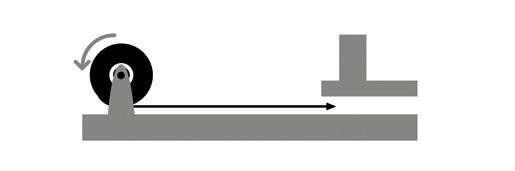
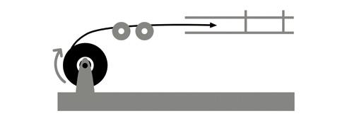
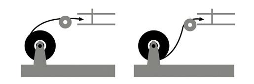
75 Feed-In setups


76 Single sheave Single sheave should only be used for guiding cables. Arrange multiple blocks to maintain bending radius whenever cable changes direction or elevation. Sheave assembly For pulling around bends, use conveyor sheave assemblies of the appropriate radius series. The pulleys must be positioned to ensure that the effective curvature is smooth and changes direction or elevation evenly at each pulley. Never allow a polygon curvature to occur as shown: 79
77 3.1.2 Pulling Loads Cables shall be so installed that the tensile stress applied to them either by reason of their own weight or for any other reason is minimised. The mechanical strength of conductors shall be sufficient for the installation and working conditions and the cross sectional area of the conductor shall not be less than 0.5 mm2. This is particularly important for cables of small cross-section and for cables on vertical runs, or in vertical pipes. These cables shall be suitably supported. Cables must be pulled with a system that enables the control of the pulling speed and the pulling load and if possible it shall be equipped with an automatic mechanical switch that will act in case the pulling load is over the previously established limit. The best option is to lay the cable applying the load to the cable through a sleeve connected to the cable conductor. This sleeve includes a ring to fix the steel cable from the pulling equipment. Maximum loads to avoid cable damages are defined as 5 kg/mm2 for Copper conductors and 3 kg/mm2 for Aluminium conductors. Cable pulling may use pulling sleeves made of a steel wire braid with an end ring, in such a way that after introduction of the cable in its interior, it will be radically compressed proportionally to the cable load. This method is less advisable as a certain cable length is damaged and must be removed, due to the radial pressure. In case of manual laying of cable it is important to distribute the load along the length, using a number of people in accordance with the cable length and numbers of rolls. If the cable contains a galvanized steel wire armour the load may be applied to the armour. In any case it should be as uniform as possible avoiding sudden efforts. In very special cases where a significant length of cable is suspended (i.e. vertical length) it may be required a steel rope to which the cable is tied every 1 to 2 meters. 80


78 3.1.3 Supporting rolls, and cable fixing It is very important to use aligning rolls to facilitate a smooth slippage of the cable and avoid its eventual contact with other elements that may damage it. The base must be sufficiently wide and safe to guarantee the stability of the drum during the unrolling of cable. The drum must be placed a minimum of 10 cm above the floor. The use of adequate rolls makes the slipping of the cable easier and reduces the pulling load. They must roll easily and include an appropriate basis to avoid its turning and a guide through which the cable passes. The distance between the rolls must be in accordance with the cable weight and flexibility characteristics, avoiding excessive distances between them, causing significant ondulations on the cable. Regarding supports and fixing, with the exception of cables for portable appliances, and those installed in pipes, conduits, trunkings or special casings, cables shall be fixed by means of clips, saddles or straps of suitable material which, if ignited, shall not contribute to any spread of flame along the cables or insulated wire. The material shall have a surface area sufficiently large and be shaped such a that the cables remain tight without their coverings being damaged. The distances between supports shall be chosen according to the type of cable and the probability of vibration. It shall not exceed 400 mm for horizontal cable run where the cables are laid on cable supports in the form of tray plates, separate support brackets or hanger ladders. The spacing between the fixing points may be up to 900 mm, provided that there are supports with maximum spacing as specified above. This exemption shall not apply to cable runs along weather decks, when the cable run is arranged so that the cables can be subjected to forces by water washing over the deck. Cables with Class 5 conductors may require additional support to prevent sagging. The supports and the corresponding accessories shall be robust and shall be of corrosion resistant material or suitably treated before erection to resist corrosion. When cables are fixed by means of non-metallic clips or straps, and are not laid on top of horizontal cable trays or cable supports, suitable metal cable clips or saddles shall be added at regular distances not greater than 1 m in order to prevent the release of cables during a fire. 81
79 Cable clips or straps used to support cable for use in high fire risk areas and safety escape routes shall be metallic unless for single core cables where clips shall be non-magnetic. 3.2 Installation temperature Low temperatures are cause of concern when installing cable. Cable should not be installed when temperatures are less than the cold bend temperature rating of the cable product plus 15ºC ( i.e., when installing a cable with a cold bend temperature rating of -25ºC, the minimum recommended installation temperature is -10ºC. The cold bend temperature ratings are indicated on the catalo spec. sheets and could be different depending on the different sheathing and insulating compounds. Prior to performing a low temperature installation, it s recommended to store the cable during 24h at a minimum temperature of 13ºC. The cable should be pulled more slowly and trained in place the same day it is removed from storage. Do not impact, drop, kink or bend cable sharply in low temperatures. 3.2 Bending radius The internal bending radius for the installation of cables shall be as recommended by the manufacturer to the type of cable chosen and shall not be less than the values given in the following table: Bending radii for cables rated up to 1,8/3kV Cable construction Insulation Covering Overall diameter of cable (D) Minimum internal radius of bend Unarmoured or unbraided 25 mm 25 mm 4Dª 6D Metal braid screened or armoured Any 6D Thermoplastic or thermosetting with circular copper conductors Metal wire armoured Metal tape armoured or metal-sheathed Composite polyester / metal laminate tape screened units or collective tape screening Any Any 6D 8D Thermoplastic or thermosetting with sector shaped copper conductors Any Any 8D ª 6D for defined circuit integrity 82
80 Bending radius for cables rated at 3,6/6kV(7,2) and above Cable construction Overall diameter of cable (D) Minimum internal radius of bend Single core cable 3 core cables Any Any 12D 9D 3.4 Colour identification Power cables up to and including 1,3/3kV The cores of multi-core cables shall be identified by the colours given in Tables 1 This table indicate the colours of rotation of those colours. Table 1- Cables with and without green-and-yellow core Colours of cores Number of cores Protective Live (2+E) 4 4 (3+E) 5 5 (4+E) The bi-colour combination green-and-yellow for the protective conductor. The colour blue for the neutral conductor. 83
81 Multiconductor control cables with more than 5 conductors for rated voltages 250V and 0,6/1kV EXZHELLENT 606 & GENFIRE 606: insulation with printed numbered cores. EXZHELLENT MAR & GENFIRE MAR: insulation with printed numbered cores. MV power cables, higher than 1,3/3kV 3 conductors Instrumentation cables 150/250 V Pair Triad Two pairs (collective screen) Two pair cables collectively screened are laid up with diametrically opposite cores Especial precautions for single core cables for a.c wiring: a.c. wiring shall be carried out, as far as possible, in twin or multicore cables. When, however, it is necessary to use single core cables for circuits rated in excess of 20 A, the following precautions shall be observed: a) The cables should either be non-armoured or they should be armoured with non-magnetic material. In order to avoid current loops, the metallic screen should be earthed at one point only. The free end of the metallic screen shall be sufficiently insulated to protect against high voltages induced by short circuit currents. b) Conductors belonging to the same circuit shall be contained within the same pipe, conduit or trunking, or the clamps, which fix them, shall included all the phases, unless they are made of non-magnetic material. c) When installing two, three or four single core cables forming respectively single phase circuits, three phase circuits or three phase and neutral circuits, the cables shall as far as possible be in contact with one another. In every case, the distance measured between the external covering of two adjacent cables shall not be greater than one cable diameter (De). 84
82 d) When single core cables having a current rating greater than 250 A must be installed near steel bulkhead, the clearance between the cables and the bulkhead shall be at least 50mm, unless the cables belonging to the same a.c. circuit are installed in trefoil formation. e) Magnetic material shall not be used between single core cables of a group. Where cables pass through steel plates, all the conductors of the same circuit shall pass through a plate or gland, so made that there is no magnetic material between the cables, and the clearance between the cables and the magnetic material shall be not less than 50 mm, unless the cables belonging to the same circuit are installed in trefoil formation. f) In order to try to equalise the impedance of three phase circuits ( of considering length, or consisting of single core cables of a conductor cross-section of 185mm 2 or larger), a transposition of the phases shall be effected at intervals not exceeding 15m. The above precautions are, however, not necessary when the cables are installed in trefoil formation. g) In circuits involving several single core cables in parallel, per phase, all cables shall follow the same route and have the same cross-sectional area. Further, the cables pertaining to the same phase shall be as far as practicable alterned with those of the other phase so that unequal division of the current is avoided. For instance, in case of two cables per phase, the correct dispositions are as follows: L 1 L 2 L 3 L 1 L 2 L 3 L 3 L 2 L or 1 L 3 L 2 L 1 Whereas the following dispositions are unacceptable: L 1 L 1 L 2 L 2 L 3 L 3 or L 1 L 2 L 3 L 1 L 2 L 3 85
83 3.6 Cable type selection Power cables In the voltage designation of cables U0 / U / (Um): U 0 is the rated power voltage between conductor and earth or metallic screen for which the cable is designed. U is the rated power frequency voltage between conductors for which the cable is designed. (U m ) is the maximum value of the highest system voltage which may be sustained under normal operating conditions at anytime and at any point in the system. It excludes transient voltage conditions and rapid disconnection of loads. U m is chosen to be equal to or greater than the heights voltage of the three-phase system. Where cables are permitted for use on circuits where the nominal system voltage exceeds the rated voltage of the cables, the nominal system voltage shall not exceed the maximum system voltage (U m ) of the cable. The choice of standard cables of appropriate voltage designations for particular systems depends upon the system voltage and the system earthing arrangements. The rated voltage of any cable shall not be lower than the nominal voltage of the circuit for which it is used. To facilitate the choice of the cable, the values of U recommended for cables to be used in three phase system, are listed in the next table in which system are divided into the following three categories: Category A. This category comprises those systems in which any phase conductor that comes in contact with earth or an earth conductor is automatically disconnected from the system. Category B. This category comprises those systems that, under fault conditions are operated for a short time, not exceeding 8 hours on any single occasion, with one phase earthed. For example, for a 13,8 kv system of Category A or B, the cable should have a rated voltage not less than 8,7/15 kv. Category C. This category comprises all systems that do not fall into Categories A and B. 86
84 The nominal system voltages from 1,8/3 kv to 8,7/15 kv shown in table 1 are generally in accordance with Series 1 in IEC For nominal system voltages intermediate between these standard voltages and also between 0,6/1 kv and 1,8/3 kv, the cables should be selected with a rated voltage not less than the next higher standard value. For example:- A first earth fault with one phase earthed causes a 3 higher voltage between the phases and earth during the fault. If the duration of this earth fault exceeds the times given for Category B, then according to Table 1, for a 6 kv system, the cable is to have a rated voltage not less than 6/10 kv. System voltage System Category Minimum rated voltage of cable U o /U Nominal voltage U kv Maximum sustained voltage Um, kv Unscreened kv Single-core or screened kv up to 0,25 1,0 3,0 3,0 6,0 6,0 10,0 10,0 15,0 0,3 1,2 A, B or C A, B or C 0,15 / 0,25 0,6 / 1 0,6 / 1 3,6 3,6 7,2 7,2 12,0 12,0 17,5 A or B C A or B C A or B C A or B 1,8 / 3,0 1,8 / 3,3 3,6 / 6,0 3,6 / 6,0 6,0 / 10 6,0 / 10 8,7 / 15 8,7 / Instrumentation and control cables The common maximum rated voltage (U) for control and instrumentation cables is 250 V. In some instances for conductor sizes 1,5 mm2 and larger, or when circuits are to be supplied from a low impedance source, 0,6/1kV rated cables are specified for use as control or instrumentation cables. 3.7 Cross section area of conductors and current carrying capacities Cross section areas of conductors The cross section area of each conductor shall be selected to be large enough to comply with the following conditions: The highest load to be carried by the cable according the installation. The corrected current rating and the highest current to be carried by the cable. The voltage drop in the circuit according the regulatory body. 87
85 The cross section area shall be able to accommodate the mechanical and thermal effects of a short circuit current. Class 5 conductors has, in most of cases, a lower conductivity than the equivalent class 2 conductor of the same nominal cross section area. The cross section area for the earth continuity conductors shall comply the following table: Arrangement of earth conductor Cross section Q of associated current carrying conductor (one phase or pole) mm 2 Minimum cross-section of earth conductor 1 i) Insulated earth conductor in cable for fixed installation. Q 16 Q ii) Copper braid of cable for fixed installation. iii) Separate, insulated earth conductor for fixed installation in pipes in dry accommodation spaces, when carried in the same pipe as the supply cable. Q % of the current-carrying conductor, but not less than 16 mm 2 iv) Separate, insulated earth conductor when installed inside enclosures or behind covers or panels, including earth conductor for hinged doors. 2 Uninsulated earth conductor in cable for fixed installation, armour or copper braid and in metal-to-metal contact with this. Q 2,5 2,5 < Q 6 Q > 6 1 mm 2 1,5 mm 2 Not permitted 3 Separately installed earth conductor for fixed installation other than specified in iii) and iv). Q< < Q 120 Same as current-carrying conductor subject to min. 1.5 mm2 for stranded earthing connection or 2.5mm2 for unstranded earthing connection. 50% of the current-carrying conductor, but not less than 4 mm2. Q > mm 2 4 Insulated earth conductor in flexible cable. Q 16 Q > 16 Same as current-carrying conductor. 50 % of the current-carrying conductor, but minimum 16mm 2. ª The term protective conductor is accepted as an alternative term for earth continuity conductor. 88
86 3.7.2 Current carrying capacities The procedure for cable selection employs rating factors to adjust the current carrying capacities for different ambient temperatures, for the mutual heating effects of grouping with other cables, methods of installation and short circuit time duty. Guidance on the use of these methods are given in IEC Current carrying capacities in continuous service at maximum rated temperature of 90ºC in accordance with IEC at ambient temperature 45ºC are as defined in the following table: Conductor temperature 90ºC Nominal crosssectional area (mm2) Single core (A) 2 cores (A) 3 or 4 cores 1, , d.c. a.c. d.c. a.c. d.c. a.c
87 These carrying current capacities in continuous service must be adjusted for ambient temperature other than 45ºC according the following table: Max conductor temperature (ºC) Ambient air temperature 35º 40º 45º 50º 55º 60º 65º 70º 75º 80º 90 1,10 1,05 1,00 0,94 0,88 0,82 0,74 0,67 0,58 0, Other considerations on the cable selection Mechanical protection In situations where there is a risk of mechanical abuse, cables shall be enclosed in suitable conduits or casings, unless the cable covering ( armour or sheath ) provides adequate protection. Metallic braiding and/or armouring can be used as mechanical protection for the cable in accordance with IEC The coverage density of the braid shall be such that the weight of the braid is at least 90% of the weight of a tube of the same metal, having an internal diameter equal to the calculated internal diameter under the braid and a thickness equal to the nominal diameter of wires forming the braid. In situations where there is an exceptional risk of mechanical damage ( holds, storage, cargo specs ) cables shall be protected by steel casing, turnking or conduits. For single pole cable constructions, armouring and braiding must be non magnetic material. Bare Copper performs better than galvanised steel and is therefore used throughout full range of cables. Installation in Metallic Pipes or Conduits or Trunking When cables are installed in metal tubes, conduits or trunking, the following precautions shall be observed. The pipes, conduits or trunking shall be suitably smooth on the interior and protected against corrosion. The pipes or conduits or trunking shall have their ends shaped or bushed in such a way so as not to damage the cable covering. 90
88 The pipes or conduits or trunking shall have such internal dimensions and radius of bend that will permit the easy drawing in and out of the cables which they are to contain: the internal radius bend shall be not less than those permitted for cables and, for pipes exceeding 63 mm external diameter, not less than twice the external diameter of the pipe. Pipes, conduits and trunking shall be so arranged that water cannot accumulate inside them (account being taken of possible condensation). The space factor (ratio of the sum of the cross-sectional areas corresponding to the external diameters of the cables to the internal cross-sectional area of the pipe or conduit or trunking) shall not be greater than 0.4. If necessary, ventilating openings shall be provided, preferably at the highest and lowest points, so as to permit air circulation and to obviate the possibility of water accumulating at any part of the pipe, conduit or trunking run. These ventilation openings should not be made if their inclusion will increase the fire risk. If there is reason to fear that a tube may break because of its length, appropriate expansion joints shall be provided. This might be the case when cable pipes are fitted along weather decks. Where cables are to be drawn into pipes or conduits or trunking, draw boxes shall be installed where necessary in order to ensure that the cables are not damaged during installation. Installation in Non-Metallic Pipes, Conduits, Trunking, Ducts or Capping and Casing. Cables may be installed in non-metallic pipes, conduits, trunking, ducts or casings either on surface or concealed behind ceilings or panelling, provided the following precautions are observed. If the fixing of capping is by means of screws, they shall be of non-rusting material arranged so as not to damage the cables. The capping shall be readily accessible. Non-metallic pipes, conduits, trunkings, ducts or cappings and casings shall, if ignited, limited the spread of flame in accordance with IEC publications. The spread of flame along the cables shall not be significantly impaired by the use of such pipes, conduits, trunkings, ducts or capping and casings, paints or other coatings Cable runs Cable runs shall be selected so as to keep the number of bends to a minimum. In the selection of cable runs, account shall be taken of the need for protection against destructive pests or rodents. 91
89 Cables having insulating materials with different maximum permissible conductor temperatures shall not be bunched in a common clip, cable transit, conduit, trunking or duct. Where this is impracticable, the cables shall be rated so that no cable reaches a temperature higher than the lowest rated cable temperature within the bunch. Cables having a protective covering which may damage the covering of more vulnerable cables shall not be bunched with the latter in a common clip, gland, conduit, trunking or duct. Cables having a bare metallic sheath or braid or armour shall be installed in such a way that corrosion e.g. galvanic or electrolytic by contact with other metals, is prevented. Cable runs shall be selected so as to avoid action from condensed moisture or drip. Cables shall, as far as possible, be remote from sources of heat such as boilers, hot pipes, resistors, etc., and protected from avoidable risks of mechanical damage. Where installation of cables near sources of heat cannot be avoided, and where there is consequently a risk of damage to the cables by heat, suitable shields shall be installed, or other precautions to avoid over heating shall be taken, for example, use of special ventilation, installation of heat insulation materials, or use of special heat resisting cables. Cables shall not be installed across expansion joints. If however, it is unavoidable, a loop of cable having a length proportional to the expansion of the joint shall be provided. The minimum internal radius of the loop during operation shall never be less than twelve times the external diameter of the cable. The flame spread performance of cables installed in bunches can be affected by a number of factors including the method of installation. (See IEC 60332) In the case of essential electrical equipment for which it is mandatory to have at least two supplies, for example, steering gear installations, the supply and any associated control cables shall follow different routes, which, as far as practicable, shall be separated both vertically and horizontally. In the case of duplicated essential electrical equipment, the supply and any associated control cables shall follow different routes, which shall be separated both vertically and horizontally as far as practicable. Where it is required to divide an offshore unit into fire zones (such as is generally the case of passenger areas), cable runs shall be so arranged that a fire in any main vertical fire zone will not affect operation of essential services in any other such zone. This requirement will be met if main and emergency cables passing through any zone are separated both vertically and horizontally as widely as is practicable and not passing through the same horizontal zone. 92
90 Cables and wiring serving essential or emergency power, lighting, internal communications or signals shall so far as practicable be routed clear of galleys, laundries, machinery spaces and their casings and other high fire risk areas, except for supplying equipment in those spaces. They shall be run in such a manner as to preclude their being rendered unserviceable by heating of the bulkheads that may be caused by a fire in an adjacent space. When it is essential that a cable shall function for some time during a fire and it is unavoidable that the cable for such a circuit is routed through a high risk area it shall be as follows: With limited circuit integrity properties in case of fire, fulfilling the requirements of the test method according to IEC or alternatively, adequate protection shall be provided against direct exposure to the fire and against mechanical damage which may occur on the site of the installation. The outer sheath of the cable shall be coloured blue for cables with limited circuit integrity in case of fire. In respect of the prevention of fire damage to cables, special attention shall be given to the protection of main cable routes for essential circuits as, for example, between machinery spaces and the navigation bridge area, taking into account the fire risk existing in accommodation spaces Fire performance All cables or insulated wiring shall meet the requirements for flame spread as given in: IEC and IEC NOTE - 1: It cannot be assumed that, because a cable or an insulated wire meets the requirements of IEC , a bunch of similar cables or insulated wires will behave in a similar manner. The flame spread performance of bunched cables is assessed by the requirements of IEC This performance requirement (i.e. for cables mounted vertically in a touching formation) has been chosen to best reflect the installation conditions generally observed on board ships. Experience has shown that the test for the flame spread of cables installed vertically is adequate for horizontal installations, all other parameters being generally the same. For systems required to maintain electrical circuit integrity under fire conditions, e.g. for fire alarm, fire detection, fire extinguishing services, remote stopping and similar control circuits, the cables shall meet the requirements of IEC Requirements for smoke emission and acid gas evolution shall be considered, and where applicable the cables evaluated in accordance with the following test methods, cables shall meet the requirements specified in the individual product standard: IEC Part 2; IEC Part 1 and IEC Part 2. 93


91 3.8.4 Flexibility for an easy installation When rules and regulations of local, regional, project or certification body permits the use of class 5 multistrand flexible Cu conductors according IEC , cables with cross section area higher than 50 mm 2 can be made with Sectorflex technology. This technology provides the cable with more handeable properties: More flexibility. More compact, smaller diameter, lighter weight. More cable per drum / coil. Same section and transport capacity as circular section. Use of conventional terminations and accessories. Sectorflex More compact, smaller diameter, lighter weight. Use of conventional terminations and accessories Hydrocarbon, Oil and MUD resistance properties. For specific oil production facilities, and according to the classification and certification bodies for each project, Oil and MUD resistant cables could be required. These cables provides the electric installation (cable) with enhanced behaviour in specific locations where oil and MUD s are present. 94
FOREWORD ONE COMPANY CONNECTING THE WORLD POWERFUL PRESENCE PRODUCTS PERFORMANCE PEOPLE
 Marine Cables FOREWORD ONE COMPANY CONNECTING THE WORLD POWERFUL PRESENCE PRODUCTS PERFORMANCE PEOPLE General Cable has been a wire and cable innovator for over 165 years, always dedicated to connecting
TRATOS OIL&GAS NEK606
 C A B L E S F O R A M O V I N G W O R L D TRATOS OIL&GAS NEK606 May 2013 Tt 08-13 TRATOS OIL&GAS NEK606 INDEX TRATOS OIL&GAS NEK606 Approvals, quality system and product certification..........................................................................
FlexFlame BFOU-XFR(i) 150/250(300)V Instr. cable. Standards applied. IEC EN 50200:2006 Annex E
 150/250(300)V Instr. cable. Standards applied. IEC EN 50200:2006 Annex E") Page 1 of 5 extended Fire Resistant, flame retardant halogen-free instrumentation cable. Mud resistant BFOU-XFR(i) 150/250(300)V MGT/EPR/EPR/TCWB/EVA Operating temperature : 90 C Operating Voltage : 150/250(300)V
Page 1 of 5 extended Fire Resistant, flame retardant halogen-free instrumentation cable. Mud resistant BFOU-XFR(i) 150/250(300)V MGT/EPR/EPR/TCWB/EVA Operating temperature : 90 C Operating Voltage : 150/250(300)V
FlexFlame BFOU(i) 150/250(300)V S3/S7 Instr. cable
 150/250(300)V S3/S7 Instr. cable") Page 1 of 5 5 4 1 2 3 Fire resistant, flame retardant halogen-free instrumentation cable. Mud resistant BFOU(i) 150/250(300)V MGT/EPR/EPR/TCWB/EVA NEK TS 606 CodeS3/S7 Operating temperature : 90 C Operating
Page 1 of 5 5 4 1 2 3 Fire resistant, flame retardant halogen-free instrumentation cable. Mud resistant BFOU(i) 150/250(300)V MGT/EPR/EPR/TCWB/EVA NEK TS 606 CodeS3/S7 Operating temperature : 90 C Operating
FlexFlame RFOU(i) 150/250(300)V S1/S5 Instr. cable
 150/250(300)V S1/S5 Instr. cable") Page 1 5 1 1 1 2 3 Flame retardant halogen-free instrumentation cable. Mud resistant RFOU(i) 150/250(300)V EPR/EPR/TCWB/EVA NEK TS 606 CodeS1/S5 Operating temperature : 90 C Operating Voltage : 150/250(300)V
Page 1 5 1 1 1 2 3 Flame retardant halogen-free instrumentation cable. Mud resistant RFOU(i) 150/250(300)V EPR/EPR/TCWB/EVA NEK TS 606 CodeS1/S5 Operating temperature : 90 C Operating Voltage : 150/250(300)V
MARINE AND OFFSHORE CABLES
 MARINE AND OFFSHORE CABLES FOREWORD General Cable is a World leader in cable manufacturing with 38 modern production facilities in North America, Europe and Oceania, employing more than 10,000 people throughout
Technical Information
 Cable Code Designation A cable code of 2 letters (1. and 4.) or 4 letters is used to describe the construction. For example: 1st Letter: Insulation: B: Fire resistant tape + insulation (Halogen-free) R:
BFOU 0.6/1kV Power Cable
 BFOU 0.6/1kV Power Cable Eland Product Group: ASH APPLICATION A flame resistant, fire retardant, halogen free cable for fixed installation in various electromechanical and electric equipment, emergency
Power & Control Cables. U o. /U 0.6/1 kv - IEC
 Power & Control Cables U o /U 0.6/1 kv - IEC 60502-1 2 KERPEN GmbH & Co. KG 07.2005 Printing errors excepted. Subject to alteration List of Contents Introduction Page B1 Construction Page B3 Use Page B4
SECTORFLEX CABLE CATALOGUE
 SECTORFLEX CABLE CATALOGUE SAVING SPACE AND TIME R & D + i SERVING OUR CUSTOMERS PRESENTATION One of the largest companies in the sector worldwide. General Cable is a leading company in the manufacture
Unarmoured Single-Core Cables to BS6883
 Unarmoured Single-Core Cables to BS TAC. EPR. SW 00/00 V 1 Application Unarmoured cable for use where mechanical protection is not required for fixed wiring in ships and in mobile and fixed offshore units
is the UK subsidary of Tele-Fonika Kable S.A., with offices and a warehouse centrally located in Leicestershire.
 is the UK subsidary of Tele-Fonika Kable S.A., with offices and a warehouse centrally located in Leicestershire. We are a major supplier of housewiring, low voltage, power and fire resistant cables for
Standardization IEC /-351/-353. Conductor material
 Low voltage power cables Fire resistant low voltage power cables according to the new demanding IEC -60331 1/2 specifications for power and lighting applications in all ship areas, with reduced diameter
A NEW BEGINNING IN OIL & GAS. Offshore Cable Range
 A NEW BEGINNING IN OIL & GAS Offshore Cable Range 2 TABLE OF CONTENTS TELE-FONIKA Kable S.A. 2 PRODUCTION POTENTIAL 3 CABLE CODE DESIGNATION 6 BS6883/BS7917 (UKOOA) 6571 SW4 0.6/1kV Single Earthing TCu/EPR/ZH
RFOU 0.6/1kV Power Cable
 RFOU 0.6/1kV Power Cable Eland Product Group: ASH APPLICATION A flame retardant halogen free power, control and lighting cable for fixed installation. Suitable for use in all conditions in a marine environment
DURAREEL TRAILING REELING CABLE
 Supplementary Technical Information Reeling and trailing material characteristics: A. Power core conductor Flexible strands tinned annealed copper complies with AS/NZS 1802, AS/NZS 2802, AS/NZS 1125, and
Power & Control Cables
 The Quality Connection Power & Control Cables U o /U 0.6/1 kv - IEC 60502-1 2 The Quality Connection www.leoni-industrial-projects.com The LEONI Group Cable expertise for the most various industrial markets.
Power & Control Cable IEC
 (2-, 3-, 4,- and 5-cores) U 0 Application For electricity supply and control in public networks and industrial plants; suitable for use in zone 1 and zone 2 group ΙΙ classified areas (IEC 60079-14). Recoended
INDUSTRIAL SOLUTIONS MARINE CATALOGUE INNOVATIVE CABLE SOLUTIONS MEETING INTERNATIONAL STANDARDS
 INDUSTRIAL SOLUTIONS MARINE CATALOGUE INNOVATIVE CABLE SOLUTIONS MEETING INTERNATIONAL STANDARDS TKF TECHNOLOGICAL LEADERSHIP IN CONNECTIVITY SOLUTIONS Since its establishment in 1930 TKF developed from
Caledonian. Caledonian Offshore & Marine Cables. BS 6883 STANDARD (Flame Retardant) BS 7917 STANDARD (Fire Resisitant)
 BS 7917 STANDARD (Fire Resisitant)") Caledonian Caledonian Offshore & Marine Cables BS 6883 STANDARD (Flame Retardant) BS 7917 STANDARD (Fire Resisitant) Caledonian, established in 1978, offers one of the most complete lines of fiber and
Caledonian Caledonian Offshore & Marine Cables BS 6883 STANDARD (Flame Retardant) BS 7917 STANDARD (Fire Resisitant) Caledonian, established in 1978, offers one of the most complete lines of fiber and
PRODUCT INFORMATION ÖLFLEX HEAT 125 C MC. Info Improved characteristics in the event of a fire GL - Germanischer Lloyd approved
 Electron beam cross-linked cables for more demanding application requirements - halogen free shielded control cable with GL certificate, special fire performance, IEC 60332-3, suitable for +125 C Info
sa B-CABLES nv PROTOLON(ST) NTSCGEWOEU Medium Voltage Flexible Cables for Use In Water sa B-CABLES nv ENERGY
 NTSCGEWOEU Medium Voltage Flexible Cables for Use In Water sa B-CABLES nv ENERGY") PROTOLON(ST) NTSCGEWOEU Medium Voltage Flexible Cables for Use In Water ENERGY Technical Data Electrical Thermal Type Type designation PROTOLON(ST) NTSCGEWÖU Approvals/ standards DIN VDE 0250 part 813
PROTOLON(ST) NTSCGEWOEU Medium Voltage Flexible Cables for Use In Water ENERGY Technical Data Electrical Thermal Type Type designation PROTOLON(ST) NTSCGEWÖU Approvals/ standards DIN VDE 0250 part 813
ÖLFLEX CLASSIC 135 CH -halogen-free control cable, HFFR, flexible and screened for various applications, U 0 /U: 300/500V
 PRODUCT INFORMATION Screened halogen-free control cable with improved fire characteristics -halogen-free control cable, HFFR, flexible and screened for various applications, U 0 /U: 300/500V Info CPR:
sa B-CABLES nv PROTOLON(ST) NTSCGEWOEU.../3E Medium Voltage Flexible Cables for Use in Water with Copper Core Shield sa B-CABLES nv ENERGY
 NTSCGEWOEU.../3E Medium Voltage Flexible Cables for Use in Water with Copper Core Shield sa B-CABLES nv ENERGY") PROTOLON(ST) NTSCGEWOEU.../3E Medium Voltage Flexible Cables for Use in Water with Copper Core Shield ENERGY Technical Data Electrical Thermal Type Type designation PROTOLON (ST) NTSCGECEWÖU.../3E Approvals/
PROTOLON(ST) NTSCGEWOEU.../3E Medium Voltage Flexible Cables for Use in Water with Copper Core Shield ENERGY Technical Data Electrical Thermal Type Type designation PROTOLON (ST) NTSCGECEWÖU.../3E Approvals/
SPECIFICATION S VR 1(4) HALOGEN FREE POWER AND CONTROL CABLE FOR MARINE APPLICATIONS LM-HF 0,6/1 kv and TEMAR PHFX-U 0,6/1 kv APPLICATI
 HALOGEN FREE POWER AND CONTROL CABLE FOR MARINE APPLICATIONS LM-HF 0,6/1 kv and TEMAR PHFX-U 0,6/1 kv APPLICATI") 1(4) HALOGEN FREE POWER AND CONTROL CABLE FOR MARINE APPLICATIONS LM-HF 0,6/1 kv and TEMAR PHFX-U 0,6/1 kv APPLICATION Power and control cable for fixed installations. Designed to fulfill requirements
1(4) HALOGEN FREE POWER AND CONTROL CABLE FOR MARINE APPLICATIONS LM-HF 0,6/1 kv and TEMAR PHFX-U 0,6/1 kv APPLICATION Power and control cable for fixed installations. Designed to fulfill requirements
Any inquiries, please feel free to contact or Caledonian
 Caledonian Low Voltage cables to IEC 60502 Standard www.caledonian-cables.co.uk www.caledonian-cables.net 1 Addison Company Profile Caledonian. established in 1978.offers one of the most complete lines
Global data. Electrical parameters
 ()TSCGEWOEU TEAX TTS 3,6/6 kv: Application Flexible medium voltage reeling cable for application under high mechanical stresses, e.g. high travel speeds, dynamic loads, multiple changes of direction into
flame Retardant overall screened Instrumentation cables (Multicore)
") Caledonian flame Retardant Instrumentation cables www.caledonian-cables.co.uk www.addison-cables.com flame Retardant overall screened Instrumentation cables (Multicore) Re-2X(st)y Re-2X(st)ysWay PVC Outer
Caledonian flame Retardant Instrumentation cables www.caledonian-cables.co.uk www.addison-cables.com flame Retardant overall screened Instrumentation cables (Multicore) Re-2X(st)y Re-2X(st)ysWay PVC Outer
Power & Control Cable IEC
 (2-, 3-, and 4-cores) U 0 Application For electricity supply and control in public networks and industrial plants; suitable for use in zone 1 and zone 2 group ΙΙ classified areas (IEC 60079-14). Recoended
Quintas & Quintas Group
 Electric Conductors Quintas & Quintas Group Index Quintas & Quintas and Solidal 2 Bare Conductors l uminium Conductors for overhead lines 3 l uminium loy Conductors for overhead lines 4 uminium Conductors
Corflex. Continuous Corrugated Aluminum Sheathed PL, MC and MV Industrial Cables. Introduction Applications... 3
 Corflex Continuous Corrugated Aluminum Sheathed PL, MC and MV Industrial Cables Introduction................................. 2 Applications................................. 3 Corflex PL 300V Instrumentation
PROTOLON (SB) PROTOLON (SB) with Copper Core Shield Flexible Cables for Trailing Operation
 PROTOLON (SB) with Copper Core Shield Flexible Cables for Trailing Operation") PROTOLON (SB) PROTOLON (SB) with Copper Core Shield Flexible Cables for Trailing Operation 2 17 BUIS_003.tif 2 18 BUIS_004.tif Selection and dimensioning criteria Refer to Section 4 for further details
PROTOLON (SB) PROTOLON (SB) with Copper Core Shield Flexible Cables for Trailing Operation 2 17 BUIS_003.tif 2 18 BUIS_004.tif Selection and dimensioning criteria Refer to Section 4 for further details
Introduction. Phone (888) Fax (800) Int l Phone Int l Fax
 Fax (800) Int l Phone Int l Fax") Introduction General Cable is a world leader in cable manufacture and one of the world s largest suppliers to the Offshore and sector. General Cable s extensive experience in the offshore market translates
Introduction General Cable is a world leader in cable manufacture and one of the world s largest suppliers to the Offshore and sector. General Cable s extensive experience in the offshore market translates
Power & Control Cable IEC
 (2-, 3-, and 4-cores) U 0 PVC-Insulation, Application For electricity supply and control in public networks and industrial plants; suitable for use in zone 1 and zone 2 group ΙΙ classified areas (IEC 60079-14).
THERMOCOUPLE CABLES THERMOELECTRICITY
 THERMOCOUPLE CABLES THERMOELECTRICITY When a metallic conductor is exposed to a difference of temperature between the two extremities, an electromotive force (emf) is generated by the temperature gradient,
Flame Retardant Individual and Overall Screened, Armoured Instrumentation Cables (Multipair)
") Caledonian Flame Retardant Instrumentation Cables www.caledonian-cables.co.uk www.addison-cables.com Flame Retardant Individual and Overall Screened, Armoured Instrumentation Cables (Multipair) RE-2X(st)YSWAY
Caledonian Flame Retardant Instrumentation Cables www.caledonian-cables.co.uk www.addison-cables.com Flame Retardant Individual and Overall Screened, Armoured Instrumentation Cables (Multipair) RE-2X(st)YSWAY
600/1000V XLPE Insulated, LSZH Sheathed, Armoured Power Cables (2-5 Cores)
") www.caledonian-s.co.uk www.addison-s.com 600/1000V XLPE Insulated, LSZH Sheathed, Armoured Power Cables (2-5 Cores) FTX400 1RZ1-R (CU/XLPE/LSZH 600/1000V Class 2) FTX400 1RZ1MZ1-R (CU/XLPE/LSZH/SWA/LSZH
www.caledonian-s.co.uk www.addison-s.com 600/1000V XLPE Insulated, LSZH Sheathed, Armoured Power Cables (2-5 Cores) FTX400 1RZ1-R (CU/XLPE/LSZH 600/1000V Class 2) FTX400 1RZ1MZ1-R (CU/XLPE/LSZH/SWA/LSZH
PRODUCT INFORMATION. UNITRONIC LiYCY. Benefits Overall shield minimises electrical interference Versatile application possibilities
 Shielded data cable with colour code according to DIN 47100 - shielded PVC data cable with colour code DIN 47100 for use in machinery and apparatus construction and in measurement, control and regulation
CONNECTING ENERGY AND INFORMATION TO GLOBAL GROWTH
 CONNECTING ENERGY AND INFORMATION TO GLOBAL GROWTH Welcome to the Prysmian Group, the world s leading cable solutions provider. Over 130 years of aggregated history, 22,000 people in 50 countries and almost
Marine Cable Catalogue NORTH EUROPE
 Marine Cable Catalogue NORTH EUROPE Linking the future As the worldwide leader in the cable industry, Prysmian Group believes in the effective, efficient and sustainable supply of energy and information
Solid PE Insulated & LAP Sheathed Air Core/Jelly Filled Cables to DIN VDE 0816
 Solid PE Insulated & LAP Sheathed Air Core/Jelly Filled Cables to DIN VDE 0816 APPLICATION The cables are designed for use as connection between central fices. The cables are suitable for installation
BS6724 SWA/LSZH Cable IEC /1000V
 BS6724 SWA/LSZH Cable IEC 60502 600/1000V Applications: Power cable suitable for power networks, where fire emission of smoke and toxic fumes creates a serious potential threat. Suitable for direct burial.
INDEX PRODUCT RANGE TRATOSFLEX- NSHTÖU-JZ TRATOSFLEX- NSHTÖU-JZK TRATOSFLEX - NSHTÖU-J TRATOSFLEX- NSHTÖU-JK TRATOSFLEX-OCS NEW TRATOSFLEX-ES *
 october 2004 TRATOSFLEX 2 Selection of type of cable in relation to use Recommended Bending Radius INDEX Current carrying capacities for continuos operation Current carrying capacities for intermittent
SPECIAL CABLES TEMPERATURE MEASUREMENT HARNESSING CABLES FOR RAILWAY TECHNOLOGY. den-belitsky / Fotolia
 SPECIAL CABLES TEMPERATURE MEASUREMENT HARNESSING CABLES FOR RAILWAY TECHNOLOGY den-belitsky / Fotolia CONTENT OVERVIEW Who we are.........................................................................................................
BS 6724 Armoured Power Cables, 600/1000V
 BS 6724 Armoured Power Cables, 600/1000V Application These cables are used for power and control circuits, they can offer excellent protection through the use of a heavy galvanized steel wire armour. The
Control Cable Type P 600/1000 volts DRILMAR 125-XE Crosslinked Polyolefin Insulated Drilling Rig and Marine Cable
 CP Jacket (overall optional) Armor (optional) CP Jacket Flexible Tin Coated Copper ed Color Coded XLPO Polyolefin Insulation 600/1000 volts Features Engineered for easiest installation. Extra flexible
ÖLFLEX CLASSIC 110 CY
 Screened PVC control cable with transparent outer sheath - PVC control cable, VDE registered, screened, flexible and numbered for various applications, U 0 /U: 300/500V Info CPR: choice under www.lappkabel.com/cpr
Electronic Instrumentation
 Applications Electronic instrumentation, analog and digital signal circuits (4-20mA). Intrinsically safe circuits. Gas and/or fluid leak detection systems. Pressure, temperature and volume measuring and
LIST OF PUBLISHED STANDARDS
 Report : 08-0-6 Page o : Of 5 LST OF PUBLSHED STDRDS Total Count: 78 umber SS umber pproved mendment SBS/TC 066 SS 97:07 7.0 Electric cables - mpregnated paper-insulated 07-0-7 metal-sheathed cables for
Wires & Cables. Next is Ready TM. Marine Cables
 Next is Ready TM Marine Cables Index S.. Description 1.. Siechem Profile Siechem Manufacturing, Laboratories & Testing Facilities 3. Siechem an early bird in Marine Cable segment in India 4. FAQ : Why
Gexol. Gexol. World Class Oil & Gas Cables. The Global Cable Solutions Company
 Gexol Gexol World Class World Class Mission-critical designed for safe, reliable performance in extremely hazardous operating environments Power Control Instrumentation VFD MMV Assembly Solutions The Global
Cables for Railway Technology
 Cables for Railway Technology www.sab-worldwide.com Content q In case that you don t find a suitable cable for your special application, we are always prepared to design a cable according to your individual
INSTRUMENTATION CABLE
 APPLICATION Used in data processing and process control. Suitable for fixed installations in damp locations and open spaces. The electrostatic screen protects against outer interference fields. Design
Type P Drilmar 125-XE Signal & Instrumentation
 Type P Drilmar 125-XE Signal & Instrumentation Crosslinked Polyolefin Insulated, Drilling Rig and Marine Cable, 600/1000 V Features Engineered for easiest installation. Extra flexible stranding meets IEEE,
PRODUCT INFORMATION. UNITRONIC LiYCY. Benefits Overall braid minimises electrical interference Multifunctional application possibilities
 Screened data transmission cable with colour code acc. to DIN 47100 : Low-frequency PVC data cable DIN 47100 coded Flexible (0.34mm² multi-wire Maxi TERMI-POINT ) Flame retardant Screened, Instrumentation
Traction Cable Radox 3 GKW/S EMC
 General Properties : Excellent high temperature, low temperature, oil, diesel oil, ozone and weathering resistance, zero halogen, flame retardant, solder iron resistant, easily strippable, flexible, excellent
Type MMV-WP Medium Voltage Wind Power Cable
 WP Type MMVWP Medium Voltage Wind Power Cable ThreeConductor: 5kV & 5kV, % Rated 05 C Renewable Energy Cables Conductors Soft annealed flexible stranded tinned copper per IEEE 580 Table and UL 07 Insulation
CABLES FOR AUTOMOTIVE MARKET Sensor and multimedia cables. Catalogue
 CABLES FOR AUTOMOTIVE MARKET Sensor and multimedia cables Catalogue Introduction Nexans has developed a range of special and customised cables for the automotive market. This cable range covers two main
Materials Evolved* BS EN BS EN IEC IEC (Upon customer request) (Red, Black) or (Brown, Blue)
 (Red, Black) or (Brown, Blue)") XLPE INSULATED AND PVC OR LOW SMOKE HALOGEN FREE (LSHF) SHEATHED CABLES Voltage Rating (Uo/U) : 00/00V, 1/0V or 00/3V Standards Complied Main Specification Materials Test Methods Flame Retardant Test Test
XLPE INSULATED AND PVC OR LOW SMOKE HALOGEN FREE (LSHF) SHEATHED CABLES Voltage Rating (Uo/U) : 00/00V, 1/0V or 00/3V Standards Complied Main Specification Materials Test Methods Flame Retardant Test Test
Type P Drilmar 125-XE Signal & Instrumentation
 Type P Drilmar 125-XE Signal & Instrumentation Crosslinked Polyolefin Insulated, Drilling Rig and Marine Cable, 600/1000 V Features Engineered for easiest installation. Extra flexible stranding meets IEEE,
0.6/1KV FLAME RETARDANT ARMORED & SHEATHED CABLE PRODUCT CONSTRUCTION 1. CONDUCTOR
 TIOI CABLE 0.6/1KV FLAME RETARDANT ARMORED & SHEATHED CABLE 1 2 3 4 5 ICC CABLE CORP. PRODUCT DESCRIPTION 0.6/1KV ONE - FIVE CONDUCTOR, MULTI-CONDUCTOR COMMERCIAL MARINE POWER & CONTROL CABLE 90 C TEMPERATURE
ÖLFLEX CLASSIC 110 H Info Benefits
 Halogen-free control cable, oil resistant and very flexible - halogen-free control cable, HFFR, oil-resistant, very flexible and cold-resistant down to -30 C for various applications, CPR Info CPR: Article
Telephone Cables Fire Warning Cables
 Telephone Cables Fire Warning Cables Telephone Cables Fire Warning Cables As supplier of underground cables, telephone cables for indoor and outdoor lying, as well as fire warning cables (also the halogen-free
RE-T2X(st)H SWAH - BS EN Mica XLPE / LSZH / CAM / SWA / LSZH Cable
H SWAH - BS EN Mica XLPE / LSZH / CAM / SWA / LSZH Cable") RE-T2X(st)H SWAH - BS EN 50288-7 Mica XLPE / LSZH / CAM / SWA / LSZH Cable Eland Product Group: I APPLICATION These cables are designed to connect electrical instrument circuits and provide counication
RE-T2X(st)H SWAH - BS EN 50288-7 Mica XLPE / LSZH / CAM / SWA / LSZH Cable Eland Product Group: I APPLICATION These cables are designed to connect electrical instrument circuits and provide counication
FTG10OM1-0,6/1KV. 50 N/mm 2 of copper section max for fixed layings
 HEPR insulated flexible with braided shield of red copper wires and plastic sheath of halogen-free flame retardant and without emission of corrosive gases. The keeps the electrical characteristics for
FR-3S Fire Resistant Cables
 FR-3S Fire Resistant Cables APPLICATION This cable is suitable use in fire extinguishing systems to operate sprinklers, control panels, exit lights in high-rise buildings, hotels, hospitals, sub-ways and
Building & Infrastructure Cables DELIVERING ENERGY
 Building & Infrastructure Cables DELIVERING ENERGY Keystone Cable is a Leading Singaporebased Cable Manufacturer and Supplier. Keystone Cable Market Reach Established since 1990, Keystone Cable has an
Data sheet chainflex CF270.UL.D
 For detailed overview please see design table 1. Outer jacket: Pressure extruded PUR mixture 2. Overall shield: Bending-resistant braiding made of tinned copper wires. 3. Banding: Plastic fleece 4. Core
Insulation Colours: Orange (Standard) Natural Natural. Sheath Colours: Orange (Standard) Orange (Standard) Bedding: Black
 Natural Natural. Sheath Colours: Orange (Standard) Orange (Standard) Bedding: Black") -I Insulated, non-sheathed Insulated and sheathed Insulated, ed and sheathed 1. : Plain stranded annealed Class 2 Copper. 1.5mm 2 up to 630mm 2 Plain stranded annealed Class 2 Copper. Plain stranded annealed
-I Insulated, non-sheathed Insulated and sheathed Insulated, ed and sheathed 1. : Plain stranded annealed Class 2 Copper. 1.5mm 2 up to 630mm 2 Plain stranded annealed Class 2 Copper. Plain stranded annealed
LOW VOLTAGE c a b l e s
 LOW VOLTAGE c a b l e s MYSORE PLANT SILVASSA PLANT MANUFACTURES A RANGE OF LOW VOLTAGE CABLES AT ITS FACILITIES AT SILVASSA AND MYSORE The Silvassa unit manufactures LV Cables since the year 2000. XLPE/
ENERGY. HYDROFIRM(T) EMV-FC S1BC4B-F 0,6/1 kv. Screened Cable for Drinking Water Application KTW/ACS
 EMV-FC S1BC4B-F 0,6/1 kv. Screened Cable for Drinking Water Application KTW/ACS") ENERGY HYDROFIRM(T) EMV-FC S1BC4B-F 0,6/1 kv Screened Cable for Drinking Water Application KTW/ACS Technical Data Trademark Type designation Specification Application HYDROFIRM(T) EMV-FC S1BC4B-F Design
ENERGY HYDROFIRM(T) EMV-FC S1BC4B-F 0,6/1 kv Screened Cable for Drinking Water Application KTW/ACS Technical Data Trademark Type designation Specification Application HYDROFIRM(T) EMV-FC S1BC4B-F Design
Type Approval Certificates for factories in Finland and China
 3 Type Approval Certificates for factories in Finland and China ABS BV CCS DNV GL KRS LRS RMRS NK RINA TC 0,6/1kV FI CN FI CN FI CN FI CN FI CN FI CN FI CN FI CN FI CN FI CN FI CN LKM-HF LKM-HF FLEX LKSM-HF
14 HH EAC/CTP CE RoHS-II conform
 Outer jacket: Pressure extruded PUR mixture Inner jacket: Pressure extruded, gusset filling PUR mixture 12 cores or more: Bundles with optimized pitch length and pitch direction Conductor: Fine-wire strand
600/1000V XLPE Insulated PVC Sheathed Power Cables (Multicore)
") 600/1000V XLPE Insulated PVC Sheathed Power Cables (Multicore) FGD400 1RV-R (CU/XLPE/PVC 600/1000V Class 2) Outdoor Cabling Earth Conductor Earth Conductor APPLICATION The cables are mainly used in power
600/1000V XLPE Insulated PVC Sheathed Power Cables (Multicore) FGD400 1RV-R (CU/XLPE/PVC 600/1000V Class 2) Outdoor Cabling Earth Conductor Earth Conductor APPLICATION The cables are mainly used in power
The cables you need when you need them
 The cables you need when you need them Whether you need standard or specialist cables you re looking in the right place. With a massive range available on short lead-times we can deliver the product you
600/1000V XLPE Insulated, PVC Sheathed, Armoured Power Cables (2-5 Cores)
") www.caledonian-s.co.uk www.addison-s.com 600/1000V XLPE Insulated, PVC Sheathed, Armoured Power Cables (2-5 Cores) FGD400 1RV-R (CU/XLPE/PVC 600/1000V Class 2) FGD400 1RVMV-R (CU/XLPE/PVC/SWA/PVC 600/1000V
www.caledonian-s.co.uk www.addison-s.com 600/1000V XLPE Insulated, PVC Sheathed, Armoured Power Cables (2-5 Cores) FGD400 1RV-R (CU/XLPE/PVC 600/1000V Class 2) FGD400 1RVMV-R (CU/XLPE/PVC/SWA/PVC 600/1000V
XLPE Cable Systems. User s guide. rev. 2
 XLPE Cable Systems User s guide rev. 2 C O N T E N T XLPE Cable Systems Page Page Introduction... 3 XLPE cable systems - design, installation and testing... 4 XLPE cables... Cable accessories... Installation
SPECIAL CABLES TEMPERATURE MEASUREMENT HARNESSING BLUELINE - CABLES FOR SHIPBUILDING.
 SPECIAL CABLES TEMPERATURE MEASUREMENT HARNESSING BLUELINE - CABLES FOR SHIPBUILDING www.sab-kabel.de CONTENT OVERVIEW Who we are.........................................................................................................
TRATOS OIL&GAS BS BS7917
 CABLES FOR A MOVING WORLD TRATOS OIL&GAS BS6883 - BS7917 Feb 2015 Tt 06-15 TRATOS OIL&GAS BS6883 - BS7917 TRATOS OIL&GAS Tratos have been involved in the Oil & Gas industry for over 40 years, manufacturing
FR-N1X1G1. Low voltage - Energy, cabling, signalling and control
 Low voltage - Energy, cabling, signalling and control FR-N1X1G1 Construction: NF C 32-323 NF C 32-323/1 Fire propagation: NF EN 60332-3-24 NF C 32-070 C1 IEC 60332-3-24 C Flame propagation: NF EN 60332-1-2
RG7H1R-1,8/3 26/45 kv RG7H1OR-1,8/3 18/30 kv
 Medium voltage - Energy RG7H1R-1,8/3 26/45 kv RG7H1OR-1,8/3 18/30 kv Structure and electrical, physical, mechanical requirements: CEI 20-13 IEC 60502 Flame propagation: EN 60332-1-2 Measurement of partial
VDE tested single cores according to EN (H05Z-K & H07Z-K) for more demanding requirements
 for more demanding requirements") VDE tested single cores according to EN 50525-3-41 (H05Z-K & H07Z-K) for more demanding requirements ÖLFLEX HEAT 125 C MC - halogen free single core with GL certificate, special fire performance, IEC 60332-3,
VDE tested single cores according to EN 50525-3-41 (H05Z-K & H07Z-K) for more demanding requirements ÖLFLEX HEAT 125 C MC - halogen free single core with GL certificate, special fire performance, IEC 60332-3,
CAN-Bus cable. CAN-Bus cable Can-Bus / Field-Bus cable for medium to maximum load requirements. chainflex cable. Overview. igus e-chainsystems
 Overview Stranding.PVC.PUR.D (4x0,25)C (2x0,5)C.020 CF11.02.02.02.LC.D igus chainflex +++ chainflex cable works +++ (4x0,5)C.PVC.021.PUR.021.021 CF11.05.01.02.LC CF11.05.01.02.LC.D.PVC.022.PUR.022.022
www. h itech controls.com (800) I (303) Click or Call for a Quotel Photo: HELUKABEL Robotic Cables C HELUKABEL
 I (303) Click or Call for a Quotel Photo: HELUKABEL Robotic Cables C HELUKABEL") Photo: HELUKABEL Robotic Cables Robotic Cables With over 30 years of experience with cables and lines, we also have the right solutions for the demands placed on the components to be installed by the applications
Photo: HELUKABEL Robotic Cables Robotic Cables With over 30 years of experience with cables and lines, we also have the right solutions for the demands placed on the components to be installed by the applications
Control Cable Type T/N 600/1000 volts DRILMAR 90 Polyvinyl Chloride/Nylon Insulated Drilling Rig and Marine Cable
 PVC Jacket (overall optional) Armor (optional) PVC Jacket Color-coded PVC/Nylon Insulation Copper ed 600/00 volts Features Maximum conductor operating temperature: 90ºC per IEEE, UL, and CSA. Meets applicable
Type P Drilmar 125-XE Power/Distribution Cable Multiconductor
 Type P Drilmar 125-XE Power/Distribution Cable Multiconductor Crosslinked Polyolefin Insulated, Drilling Rig and Marine Cable, 600/1000 V Features Engineered for easiest installation. Extra flexible stranding
CORDAFLEX(SMK) (N)SHTÖU Tough Rubber-Sheathed Reeling Cables
 (N)SHTÖU Tough Rubber-Sheathed Reeling Cables") CORDAFLEX(SMK) (N)SHTÖU Tough Rubber-Sheathed Reeling Cables 3 SK1_1-001.tif 4 SK1_1-003.tif SK1_1-00.tif Selection and dimensioning criteria Refer to Section 4 for further details Ü Type CORDAFLEX(SMK)
CORDAFLEX(SMK) (N)SHTÖU Tough Rubber-Sheathed Reeling Cables 3 SK1_1-001.tif 4 SK1_1-003.tif SK1_1-00.tif Selection and dimensioning criteria Refer to Section 4 for further details Ü Type CORDAFLEX(SMK)
POLYCAB WIRES PVT. LTD.
 POLYCAB INDUSTRIAL JELLY FLOODED COAXIAL CABLES Polycab Gas Injected Physical Polyethylene Foam Insulation with Laminated Aluminium Tape and Aluminium Wire Braid, Jelly Flooded PVC Black Jacketed Industrial
CF270.UL.D.
 Outer jacket: Pressure extruded PUR mixture Overall shield: Bending-stable braid made of tinned copper wires Core insulation: Mechanically high-quality, especially low-capacitance TPE mixture Conductor:
MEDIUM VOLTAGE POWER CABLES
 MEDIUM VOLTAGE POWER CABLES CONTENTS 1 GENERAL INTRODUCTION 4 TECHNICAL INFORMATION 15 25 35 45 Single Core XLPE Insulated PVC Sheathed Cables UNARMOURED CABLES COPPER UNARMOURED CABLES ALUMINUM ALUMINUM
ENERGY. TECWATER EMV-FC S1BC4N8-F 0,6/1 kv. Screened Cable for Water Application
 ENERGY TECWATER EMV-FC S1BC4N8-F 0,6/1 kv Screened Cable for Water Application Technical Data Trademark Type designation Specification Application TECWATER EMV-FC S1BC4N8-F Design and tests according to
ÖLFLEX CLASSIC 130 H - halogen-free control cable, HFFR and flexible for various applications, U 0 /U: 300/500V
 Halogen-free control cable with improved fire characteristics - halogen-free control cable, HFFR and flexible for various applications, U 0 /U: 300/500V Info CPR: choice under www.lappkabel.com/cpr For
PVC INSULATED HEAVY DUTY CABLES
 PVC INSULATED HEAVY DUTY CABLES 1100 V. 9001:2008 14001:2004 OHSAS 18001:2007 Details make the Difference IS 1554 (Part I) Product Range L.V. PVC & XLPE POWER CABLES WITH COPPER AND ALUMINIUM CONDUCTOR
OFFSHORE WIND FEASIBILITY STUDY APPENDICES Appendix C.2 Subsea Cable Data Sheets
 OFFSHORE WIND FEASIBILITY STUDY APPENDICES 10-7 10.3.2 Appendix C.2 Subsea Cable Data Sheets Design data for TFVA 36 kv 3x1x240 mm 2 KQ Metallic Laying up Inner sheath Bedding Armor Diameter of conductor
Rubber was the first insulant to be used in Electric Cable manufacture but gave way to other insulants like paper, PVC, XLPE etc.
 INTRODUCTION : Rubber was the first insulant to be used in Electric Cable manufacture but gave way to other insulants like paper, PVC, XLPE etc. Rubber is still considered the preferred insulation for
LDC Pricelist. ( WEF 1st August 2017 ) "POLYCAB" 4 Pair Unshielded Twisted Pair (UTP) LAN (Computer) Cables. Unarmoured.
 POLYCAB 4 Pair Unshielded Twisted Pair (UTP) LAN (Computer) Cables. Unarmoured.") INDUSTRIAL JELLY FLOODED COAXIAL CABLES LDC Pricelist LAN (COMPUTER) CABLES "POLYCAB" Gas Injected Physical Polyethylene Foam Insulation with Laminated Aluminium Tape and Aluminium Wire Braid, Jelly Flooded
INDUSTRIAL JELLY FLOODED COAXIAL CABLES LDC Pricelist LAN (COMPUTER) CABLES "POLYCAB" Gas Injected Physical Polyethylene Foam Insulation with Laminated Aluminium Tape and Aluminium Wire Braid, Jelly Flooded
PROTOLON(FL)-LWL (N)TSFLCGEWOEU 3,6/6 kv: medium voltage flat reeling cable with fibre-optics
-LWL (N)TSFLCGEWOEU 3,6/6 kv: medium voltage flat reeling cable with fibre-optics") PROTOLON(FL)-LWL (N)TSFLCGEWOEU 3,6/6 kv: medium voltage flat reeling cable with Application Flexible medium voltage reeling cable for high mechanical stresses (e.g. dynamic tensile loads, multiple changes
PROTOLON(FL)-LWL (N)TSFLCGEWOEU 3,6/6 kv: medium voltage flat reeling cable with Application Flexible medium voltage reeling cable for high mechanical stresses (e.g. dynamic tensile loads, multiple changes
0.6/1KV FLAME RETARDANT UNARMORED CABLE PRODUCT CONSTRUCTION 1. CONDUCTOR CROSS-LINKED POLYETHYLENE (XLPE) IEEE 1580 COLOR CODE 3.
 IEEE 1580 COLOR CODE 3.") TI CABLE 0.6/1KV FLAME RETARDANT UNARMORED CABLE 1 2 3 ICC CABLE CORP. PRODUCT DESCRIPTION 0.6/1KV ONE - FIVE CONDUCTOR, MULTI-CONDUCTOR COMMERCIAL MARINE POWER & CONTROL CABLE 90 C TEMPERATURE RATING
TI CABLE 0.6/1KV FLAME RETARDANT UNARMORED CABLE 1 2 3 ICC CABLE CORP. PRODUCT DESCRIPTION 0.6/1KV ONE - FIVE CONDUCTOR, MULTI-CONDUCTOR COMMERCIAL MARINE POWER & CONTROL CABLE 90 C TEMPERATURE RATING
POLYCAB WIRES PVT. LTD.
 Size (sq.mm.) 0.75 (Amps) 7 830 880 950 (No. of 28 12 1 12 1070 1130 1230 24 12 1.5 16 1600 1690 1840 16 10 2.5 22 2580 2730 2960 12 6 4 29 3800 4030 4370 8 4 6 37 5640 5980 6490 6 3 10 51 9920 10520 11410
POLYCAB WIRES PVT. LTD.
 POLYCAB INDUSTRIAL JELLY FLOODED COAXIAL CABLES Polycab Gas Injected Physical Polyethylene Foam Insulation with Laminated Aluminium Tape and Aluminium Wire Braid, Jelly Flooded PVC Black Jacketed Industrial