1:8 SCALE NITRO POWERED TOURING CAR
|
|
|
- Martin Williams
- 6 years ago
- Views:
Transcription


1 1:8 SCALE NITRO POWERED TOURING CAR RTR INSTRUCTION MANUAL *SPECIFICATIONS ARE SUBJECT TO CHANGE WITHOUT NOTICE. SAFETY PRECAUTIONS! This radio control models is not a toy! - First time builders should seek the advice from people having building experience in order to assemble the model correctly and to produce it's performance to full extent. - Assemble this kit and places out of children's reach! - Take safety precautions while operating this model. You are responsible for this models assembly and safe operation! - Always keep this instruction manual ready at hand for quick reference, even after completing the assembly.


2 REQUIRED FOR OPERATION THINGS NEEDED You will need to buy a few items to start the engine and run the car. Use 20% nitro CAR fuel. Do not use airplane or heli fuels, they will over heat engine. Buy long glow plugs, like OFNA/PICCO Plug (#51007). Use plugs without idle bar. Do NOT buy hot plugs, like the MC-59. In your box you will find.. # Bottle, spout top # Red C size glow heater Glow Fuel 20% AA Batteries ( 12 pcs ) #10211 NiHm Flat Pack You need to get batteries for the radio transmitter and the car receiver packs. Radio TX needs (8) eight AA batteries Car needs (4) four AA batteries. Recommendation Option: You may want to upgrade the car battery pack to a Ni-Cad or NiHm 5 cell type(600ae). This will give more run time. OFNA # NiMh Flat Pack and NiHm Battery Charger #10214 TOOLS NOT INCLUDED IN KIT Cutter Instant Cement Phillips Type Drivers ( L ) Curved Scissors Masking Tape Phillips Type Drivers ( S ) Brush Cross Wrench #17109 $3.95 Needle Nose Pliers Paints Knife Glow Plug & 17MM Cross Wrench #10801 $6.95 Grease
3 READ THIS BEFORE RUNNING Running a nitro kit is fun and easy, but to make this a safe and good experience you must observe a few rules. This kit is extremely fast, easily over 40MPH, and can seriously injure someone if you are not careful. Where to run car? Any running area you choose must be dry. Do not run car near any water or wet dirt. Do not run on public streets. It is very easy to have the car run over or damaged by hitting the curb. Do not operate car in tight confined places. The car is very fast and will easily hit something. Do not run near people or animals. The car is very fast and will too easily hit someone. Due noise, you will want to consider the surrounding area when operating the car. Do not operate the car at night. You will not be able to drive it without hitting something. Do not operate the car indoors. Engine exhaust is not healthy. Glow Fuel Glow fuel is poisonous! Glow fuel is flammable! Do not leave in fuel bottle with lid off at any time. Don use any fuel other than glow fuel in this engine. First Time Starting the Engine Caution! When starting engine make sure the following is observed. Set engine Master needle to 3 turns (rich setting) Do not do this alone, get an experienced friend to help at first. Fill fuel tank, try not to spill fuel. Do not spill fuel on receiver Hold car off the ground, so it will not runaway when first starts Turn on Radio and check the linkage before starting engine. Turn on car receiver battery switch. Always have an air filter on the carburetor to keep dirt out. Engine Break-in See Engine Page. Emergency Stopping Engine When Running Remove air filter and cover carb. intake. Squeeze fuel line and hold until engine stops. With a rag, cover exhaust outlet. Storing Car After Running Remove fuel from tank and fuel lines Turn off radio in car Put a few drops of after run in engine to keep it from rusting. Clear oil and dirt from chassis with a degreaser. Precautions This kit is not a toy. Always run car with a second person as a spotter and pitman. Hot Parts - The pipe, manifold, engine and head are very hot and will cause burns. Rotating Parts - Keep hands away from the drive train, wheels, and engine when engine is running. Radio - Check batteries life before running the car. If radio does not have full control of the car with steering and/or throttle/brake do not run until corrected. Failure to correct this will result in possible injury and damage to the car or property. Glow fuel - Do leave the glow fuel unattended with the lid off. Fuel contains Methanol and Nitro Methane and is flammable and poisonous. Store fuel in cool ventilated location. Refer the glow fuel label for additional precautions. Car Fuel tank - Never store fuel in car tank, it will ruin the engine if left in tank. Always turn off the car BEFORE turning off radio. DAMAGE DUE CAR RUN AWAY IS NOT A WARRANTY ISSUE. IF YOU DO NOT BREAK-IN ENGINE CORRECTLY, MAINLY AT LOW RPM, YOU WILL BREAK THE CONNECTING ROD! FAILURE TO NOT READ AND FOLLOW BREAK-IN ENGINE INSTRUCTIONS WILL VOID WARRANTY!
 #10300 Alum.Stopper Plastic Collar * Align throttle servo same as shown.")

. 2.Turn on transmitter. 3.Turn on receiver. 4.Center throttle trims as shown. A B C 1.")
 Brake (C) IMPORTANT CHECK RADIO THROTTLE AND STEERING SWITCHES BEFORE RUNNING CAR * Insert into transmitter.")
4 ASSEMBLY OF THE THROTTLE LINKAGE SYSTEM #30800 Plastic Throttle kit 3X Set 2mm Rod #30530 Plastic Throttle Ball Joint * Snap On. 3X Set Throttle Spring 3X Set #10300 Alum.Stopper Fuel Tube ( 6mm ) #10300 Alum.Stopper Plastic Collar * Align throttle servo same as shown. * Take the plastic collar from brake system plastic parts. Brake Idle Position Place battery pack in a plastic bag before securely tie wrap pack to radio plate. Pack will fall out if not securely mounted! Check the battery pack if you have any radio interference, don t run car if you see a problem.. Full Throttle CHECKING ENGINE THROTTLE 1. Insert AA batteries into transmitter (8 Pcs). 2.Turn on transmitter. 3.Turn on receiver. 4.Center throttle trims as shown. A B C 1. Pull Full Throttle. 1. Push trigger to full brake position. 2. Adjust alum. Stopper to increase or decrease the brake. * Align throttle servo same as shown. A Idle Position (A) Brake (C) IMPORTANT CHECK RADIO THROTTLE AND STEERING SWITCHES BEFORE RUNNING CAR * Insert into transmitter. Full Throttle (B) Full throttle arm position. Spring rod pulls throttle barrel open and brake rods release pressure on brake cams. B B A C C Full brake arm position. Spring compresses forward and brake rods pull brake levers.
5 SHOCK ASSEMBLY * Fit into groove. Oil Seal 2.6 x 5mm Washer 2.6mm Nut 7mm E-Ring 2mm Washer 1mm Washer Rebuild Kit * Note the E-Ring must fit into groove as shown Dust Pusher, Short (Yellow Rubber) Dust & Shaft Protector, long *Push onto shock cylinder Front. 3.5mm Short Shaft * Short shaft for front. Shock Shaft Front Shaft, 3.5mm with Piston Piston Cement * Assembly 4 pieces of the shock shaft. E-Ring ( Make 2 for front.) mm Ball End Rear, 3.5mm Long Shaft * Long shaft for rear Rear Shaft, 3.5mm with Piston ( Make 2 for rear. ) mm Ball End * Be careful not to damage shock shaft. FILLING THE SHOCKS WITH OIL 1. Pull down piston and pour oil into shock cylinder. Remove air bubbles by slowly moving piston up and down. 2. Pull down piston, attach pressure top and shock oil overflow with tissue paper. 3. Tighten up shock cap. Silicone Oil Cap, blue *Leave. * down cap. UP down Pressure Top *Move Slowly. * Fit into groove. ASSEMBLY OF THE SPRING Misc. Plastic Shock Parts mm Ball Joint Spring Holder Front, Spring Pair, GTP Rear, Spring Pair, GTP *Slide spring collar into Shock. * Push 6mm ball joint into ball end. Spring Collar Misc. Plastic Shock Parts (Standard) 5mm 1mm *Spring Tension adjust er.
6 ASSEMBLY OF NEW K STYLE DIFFERENTIAL CASE AND GEARS FRONT OR REAR DIFF UNIT CENTER DIFF UNIT x 12.8mm Pin Diff. Bevel Gear ( Large ) Diff. Shaft x 10mm Washer Diff. Bevel Gear ( Small ) mm Cross Pin Diff. Bevel Gear ( Small ) x 10mm Washer * Position the O-ring as shown P5 O-Ring ( Orange ) x 26mm O-Ring mm Cross Pin Diff. Bevel Gear ( Small ) x 10mm Washer NB. It is very important to remove the shim if the mesh is too tight. Grease * Apply diff. Gear grease to the differential, during assembly. * Fill the diff. Case to approx 70% with grease Diff. Case ( Front/Rear ) Diff. Case (Center ) x 12.8mm Pin Diff. Shaft P5 O-Ring ( Orange ) 3x10mm Tapping Diff. Bevel Gear ( Large ) Diff. Case ( Front/Rear ) Diff. Case (Center ) 3x10mm Tapping ASSEMBLY OF THE BEVEL GEAR ( Builds two differentials for front and rear. ) Bevel Gear Optional - Bevel Gear (Large/Metal) (Harden Steel) Tube x 5mm Cement x 5mm Set x 5mm Set Cement Cap Joint x 19mm Bal lbearings * Push tubes into holes of the diff. Case Tube * Notice the straight holes are for front and rear x 5mm (Small Head) 5 x 5mm Set 3 x 5mm x 19mm Ball bearings Cap Joint
7 ASSEMBLY OF THE SPUR GEAR (Solid Center Drive) X 5mm Set Spur Gear Cement Center Gear Shaft Center Gear Mount Brake Joint, Drive Cup 7 x 19x 5mm Ball Bearings 7 x 19x 5mm Ball Bearings 3 x 10mm Brake Joint, Drive Cup Cement Center X 5mm Diff. Mount Center Set Diff. Mount X 5mm Set ASSEMBLY OF THE CENTER PLATE Brake Disc 1 2 (Steel) 3x12mm 3 x 10mm Tapping * Apply instant cement to glue brake pad and packing. (Rear) Brake Pad Brake Pad Packing 3 (Front) Center Diff. Mount (Front) 3 x Set Cement Leave 0.5mm Center Plate Plastic Bearing or Flange Ball Bearing, option Brake Cam Brake Lever
8 ASSEMBLY OF THE GEAR BOX ( Assemble two gear boxes for front and rear. ) Gear Box Cement 2 5 x 5mm Set * Place set screw in D cut x 13 x 5mm Ball Bearing Cap Joint Bevel Gear * Insert two ball bearings as shown x 13 x 5mm Ball Bearing Gear Box * Make two gear boxes for front and rear. 4 x 20mm Flat Head Tapping 4 x 20mm Flat Head Tapping Front Diff. Assembly Gear Box Cover ASSEMBLY OF THE FRONT SHOCK TOWER Front Shock Tower,GTP * Insert the stabilizer before assembly th shock stay. 4 x 10mm Tapping 4 x 10mm Tapping Stabilizer Bar
9 ASSEMBLY OF THE FRONT ARM HOLDER 4x10mm Tapping 3 x 20mm Flat Head Tapping x 15mm Tapping ( Small Head ) x 15mm Tapping ( Small Head ) Front Lower Arm Holder 4 x 10mm Tapping ( Small Head ) ASSEMBLY OF THE FRONT PIVOT BALL KNUCKLE ARM Ball Type Knuckle Arm ( Right and Left ) * Adjust alum. Nut to keep steering ball smoot. Assembly of the right and left hand side are the same. R * Note the "R" mark is for righthand side. * Use 5mm hex wrench mm Alum. Nut Steering Ball Washer mm Steering Ball x16mm Ball Bearing R 8mm Axle CVA Constant Velocity Axle x16mm Ball Bearing ASSEMBLY OF THE FRONT KNUCKLE ARM INTO FRONT ARM Front Upper Arm Assembly of the right and left hand side are the same. * A 4 x 10mm set screw is used to adjust the ride height. 4 x 10 mm Set x4mm Set * Approx x 17mm Pin R Wheel Hub ( Alum. ) * Use 2.5mm Hex Wrench Front Lower Arm 3.5mm
10 ASSEMBLY OF THE FRONT ARM ONTO GEAR BOX Assembly of the right and left hand side are the same. 3 x 20mm Cap E-Ring 3x25mm Cap Cement Flange Nut 5 x 5mm Set 3 mm E-Ring M3 Flange Nut ( Steel ) 1 0 5x5mm Set R Lower Arm Shaft * Do not over tighten 5x5mm set screw. * Insert drive shaft before assembly. E-Ring E-Ring 3 x Set 3 mm E-Ring R Upper arm Shaft E-Ring ASSEMBLY OF THE CASTER ADJUSTER * use adjuster to change the caster angle Caster Angle Adjuster Caster angle will become bigger. Caster angle will become less. 1 0
11 ASSEMBLY OF THE REAR SHOCK TOWER Rear Shock Tower, GTP & WII 3 x 20mm Flat Head Stabilizer Bar * Insert stabilizer before assembly of the shock tower M3 Nylon Lock Nut * Don't over tighten tapping screw Rear Lower Arm Holder 4x16mm Flat Head Tapping E-Ring M3 Nylon Lock Nut Assembly of the right and left hand side are the same Arm Shaft (Long) 3 x 15mm * A 4 x 10mm set screw is used to adjust the ride height. 4 X 10mm Set * Approx Rear Wheel Toe-in Cams E-Ring Rear Lower Arms 1 Degree 1.5 Degree E-Ring * Set triangle marks in the direction shown in Fig.1. Fig.1
12 ASSEMBLY OF THE REAR HUB Rear Hub * Builds two upper Rods for left and right side x60mm Turnbuckle x 16 x 5 Ball Bearings x 16 x 5 Ball Bearings Rear Wheel Axle Shaft mm Plastic Arm Ball End mm Plastic Arm Ball End x 17mm Pin mm Ball * Anticlockwise mark Wheel Hub ( Alum. ) 42mm Assembly of the right and left hand side are the same mm ASSEMBLY OF THE REAR DRIVE SHAFT Assembly of the right and left hand side are the same mm E-Ring * Insert rear drive shaft befor assembly Rear Drive Shaft 5x5mm Set * Do not r tighten 5x5mm set screw over tighten mm E-Ring Rear Arm Shaft
13 ASSEMBLY OF THE REAR UPPER ARM ROD Assembly of the right and left hand side are the same. 3 x 20mm Cap M3 Nylon Lock Nut 3 x 20mm Cap 3 X 25mm Cap Cement Cement Nylon Lock Nut Flange Nut * Insert into rear hub. Nylon Lock Nut 3 x 15mm 3 x 25mm Cap ASSEMBLY OF THE REAR STABILIZER ROD mm Stabilizer Ball End X 30mm Tie Rod mm Stabilizer Ball End 15mm mm 3 x Set Cement mm Stabilizer Ball End mm Ball Joint 3 x 15mm * Insert the stabilizer rod into arms before assembly. 3 x 15mm
14 ASSEMBLY OF THE SERVO SAVER (36740 Servo Saver Plastic parts) mm E-Ring Servo Saver Horn A 3 x 15mm Servo Saver Bushing Servo Saver Horn B mm E-Ring Servo Saver Bushing Servo Saver Top Adapter Servo Saver Spring Servo Saver Horn B Plastic Tube x12mm Washer mm E-Ring Servo Saver Shaft (Brass) Servo Saver Shaft (Brass) mm E-Ring Nylon Lock Nut Servo Saver Connector Nylon Lock Nut M3 Nylon Locknut 3 x 15mm 6 mm E-Ring ASSEMBLY OF THE FRONT PLATE AND STEERING ROD * Made two steering rods for left and right-side. 3 X 10mm Front Plate x 46mm Turnbuckle mm Steering Ball End mm Ball & Socket mm Ball & Socket mm Steering Ball End * Anticlockwise mark. ( Left-Side ) 35mm Servo Saver Post ( Right-Side) 35mm mm
15 ASSEMBLY OF THE FRONT PLATE AND STEERING ROD 3x15 Flat Head Front Steering Rod ( Left ) 3 x 15mm Flat Head Front Steering Rod ( Right ) 3x10mm Tapping µ Û ð úá³ 3 x 20mm Flat Head ASSEMBLY OF THE FRONT PLATE ONTO THE FRONT GEAR BOX Knuckle Arm ( Left-Side ) 3 x 20mm Flat Head Nylon Lock Nut R x 10mm Tapping Nylon Lock Nut 3 x 20mm Flat Head nylon Lock Nut ASSEMBLY OF THE STABILIZER ROD (#30340 Anti-roll Kit) mm Stabilizer Ball End X 30mm Tie Rod 3 x Set mm Stabilizer Ball End mm Ball Joint 3 x 15mm mm Ball Joint R mm mm * Insert stabilizer rod into upper arm. 30mm Assembly of the right and left hand side are the same.
16 ASSEMBLY OF THE FRONT GEAR BOX ONTO CHASSIS 3 x 25mm Flat Head Tapping R Chassis * A 3 x 10mm flat head screw are for servo post. 3 x 25mm Flat Head Tapping 3 x 10 mm Flat Head 3 x 10mm Flat Head ASSEMBLY OF THE FRONT BUMPER R Front Bumper, GTP 4 x 20mm Flat Head Tapping 4 x 20mm Flat Head Tapping 4 x 20mm Flat Head Tapping
17 ASSEMBLY OF THE CENTER DRIVE SHAFT Center Gear Assembly Center Drive Shaft (Front) * Insert drive shaft into cap joint Chassis 4 x 16mm Flat Head Tapping R x 16mm Flat Head Tapping x4 4 x 16mm Flat Head Tapping x4 3 x 25mm Flat Head Tapping x Center Drive Shaft (Rear) * Insert drive shaft into cap joint. 4 x 16mm Flat Head Tapping 3 x 25mm Flat Head Tapping ( 2 Pcs ) 4 x 16mm Flat Head Tapping
18 ASSEMBLY OF THE STONE GUARD Nylon Stone Guard (Left-Side) Nylon Stone Guard (Right-Side) x 10mm Flat Head Tapping 3 x 10mm Flat Head ( 3 Pcs)
19 3 x 5mm 3 X 8mm Washer Notes: Non-Pull Start Engines... Alum. Washer behind the flywheel is not needed when using Force engines or similar types. O.S. Engines will require washer spacer. To check!..place the brass corn against the engine bearing, then flywheel. You should be covering one or two thread of the engine shaft. If this is the case, you do not need an additional washer behind the flywheel. ASSEMBLY OF THE CLUTCH INTO ENGINE 3 x 20mm Cap Nylon Locknut You must cut the engine shaft if too long. Count 6 threads in front of the flywheel and mark. This is all you need to tighten the clutch nut and mount the flywheel. Force Pull Start Engine... Force Pull Start Engines required NO spacer and no shaft cutting. The engines comes with an alum cast driver washer, you use this part as the spacer, not the alum. washer shown. Also, use the special flywheel brass corn. This corn fits the thread shaft diameter so you can tighten the flywheel against the drive hub. 3 x 20mm Hex 3 x 20mm Hex # T # T # T (stock) # T # T # T # T Clutch Bells # x10x4mm Ball Bearing #10100 Clutch Spring # x10x4mm Ball Bearing #10010 Clutch Shoes Black Type #10329 Brass, Corn (sml hole) SEE NOTES ABOVE Nylon Lock Nut 3 x 5mm 3 x 8mm Washer Misc. Hardware #10099 #10091 Clutch Nut screw type * Shoes are trailing. #10040 (stock) 3 Pin Flywheel, Taper # Pin Flywheel, Hole #30480 Engine Mount Nylon Lock Nut * Fit the flywheel using a cross wrench or deep socket. If engine turns when tightening, hold piston with large thick tie-wraps and hard wood in exhaust port. Do not use metal, it will damage engine. * Place the clutch shoes with the clutch springs over the 3 pins of the flywheel. Using a screw driver as a lever, bend the small end of the clutch spring behind the clutch nut and press down to snap shoe in place. #10098 SG Nut & Shim KiT Engines with ground shafts and few threads are called SG Shaft. A special clutch nut is needed. The stock flywheel (#10040) is fine. ASSEMBLY OF THE AIR FILTER You must oil foam filter before use. Filter will not work if not oiled. Clean with soap and water only. You will damage foam if washed if fuel! Nylon Strap ( Small ) # Black # Yellow # Pink # Blue Air Filter Connector Nylon Strap ( Small ) #10016 Air Filter Sponge Refills # Blue # Yellow # Rose Foam Air filters Unit 3 x 10mm Tapping

20 INSTALLATION OF THE FUEL TANK AND ENGINE ONTO CHASSIS 3 x 15mm Pressure Nipple Note Book Paper Fuel Tank Fuel Nipple 3 x 15mm *Use note book paper to set gear backlash between spur gear and clutch bell gear. If the space is not correct the spur gear will be damaged. Spur Gear 3 X 20mm Cap 90 degree Clutch Bell Plastic Post Plastic Post * Loose or tighten 3x20mm cap screw and 5x10mm hex screw to align spur gear and clutch bell gear to 90 degree. 3 x 10mm Tapping 3 x 10mm Tapping x12mm Washer ( 4 pcs ) 5x10mm Hex ( 4 pcs ) ASSEMBLY OF THE MANIFOLD AND MUFFLER * Read this page with very carefully Manifold Adapter ( Red Silicone ) Manifold Manifold Spring 4mm Nylon Lock Nut *Tighten the strap and cut off the excess Muffler Wire Nylon Strap ( middle ) 4x1omm Flat Head 5x5mm Set Muffler Pressure Nipple * Drill a hole (Size 3.5mm) in the place and align as shown. Use a two part epoxy glue to full seal the nipple base to the nipple Silicone Tube
21 ASSEMBLY OF THE FUEL TUBE * Connect to fuel tank pressure nipple. * Connect to carburetor. Fuel Tube * Connect to * Connect to fuel nipple. press nipple. ASSEMBLY OF THE RADIO TRAY AND SERVO 3 x 10mm Tapping 3 x 10mm Tapping 3 x 10mm Tapping * Use the screw provided with your witch Radio Tray 3 x 10mm Tapping Cover of the receiver box Receiver Box 3 x 10mm Tapping Radio Tray Pos, Nylont Radio Tray Post, Alum Switch Cover * Connect switch wire to receiver. Switch * Connect battery case wire to switch. 3 x 10mm Tapping Receiver Throttle Servo Battery Case Steering Servo Servo Mount * Connect the wire to receiver Servo Mount
22 ASSEMBLY OF THE REAR STIFFENER Rear Stiffener 3 x 10mm 2.6x10 Tapping 2.6x10 Tapping * Use the small strap to secure the servo wire. ASSEMBLY OF THE BRAKE SYSTEM ( Use #30800 brake linkage plastic parts set. ) 3x12mm Slider 2x8mm 2x4mm 2x6mm Washer 3X Set Servo Mount 2x25mm 2mm Tie-Rod End Servo Horn Cement mm Adjust Nut Adjust Mount Nut 2mm Nut 2x6mm Washer 2x4mm 2mm Tie-Rod End ASSEMBLY OF THE SERVO HORN LINKAGE INTO SERVO * Use the screw provided with your radio mm Rod * Use the screw provided with your radio. Steering Servo Horn
23 ASSEMBLY OF THE STONE GUARD Assembly of the right and left hand side are the same Nylon Stone Guard (Left-Side) Nylon Stone Guard (Right-Side) 3 x 10mm Flat Head ( 3 Pcs) Antenna Tube Antenna Post
24 ASSEMBLY OF THE THROTTLE LINKAGE SYSTEM (Part of linkage kit) 3X Set mm Rod Throttle Ball Joint * Snap On. 3X Set Throttle Spring 3X Set Alum.Stopper Alum.Stopper Plastic Collar * Take the plastic collar from brake system plastic parts. * Align throttle servo same as shown. Brake Idle Position Full Throttle ALIGN THROTTLE SERVO AND BRAKE SAME AS SHOWN ( Neutral Position ) Engine at idle ( Braking Position ) Brake is not on Brake is on Less Brake Brake Adjust Nut ( Full Throttle Position ) More Brake Engine at full throttle Loose Tighten * Tighten or loose the adjuster nut will change the brake. Brake is not on
25 ASSEMBLY OF THE FRONT STEERING ROD mm Ball & Socket X 30mm Tie Rod mm Ball End 20mm mm mm Ball & Socket mm Ball End 3x12mm 3x12mm * Align the steering servo as shown. 3x10mm Tapping Front Stiffener 3 X 10mm
26 ASSEMBLY OF THE FRONT AND REAR SHOCKS ONTO THE SHOCK TOWER Assembly of the right and left hand side are the same. Plastic Washer or Use CNC Alum Spacer, 4 purchase. #36507 $4.95 R mm Ball Joint 3 x 8mm Washer Cement 3 x 15mm Nylon Lock Nut 3 x 15mm Nylon Locknut * Insert shock ball end into arm. 3 X 8mm Washer Assembly of the right and left hand side are the same. Plastic Washer mm Ball Joint 6mm ²yÀY 3 x 8mm Washer Cement Nylon Lock Nut 3 x 15mm * Insert shock ball end into arm.
27 ASSEMBLY OF THE FRONT BODY POST Body Post Set Front Body Post R 1 0 ASSEMBLY OF THE FRONT FOAM BUMPER 4x15mm Tapping (Small Head) Foam Bumper Cover Foam Bumper Body Supporter Clips R R Clips
28 ASSEMBLY OF THE REAR BODY MOUNT Nylon Nut Body Mount Rear Body Post 2mmNut 2x18mm 3 x 15mm 3 x 15mm ASSEMBLY OF THE REAR BODY SUPPORT Body Supporter Clips Clips * Use this body post for rear.
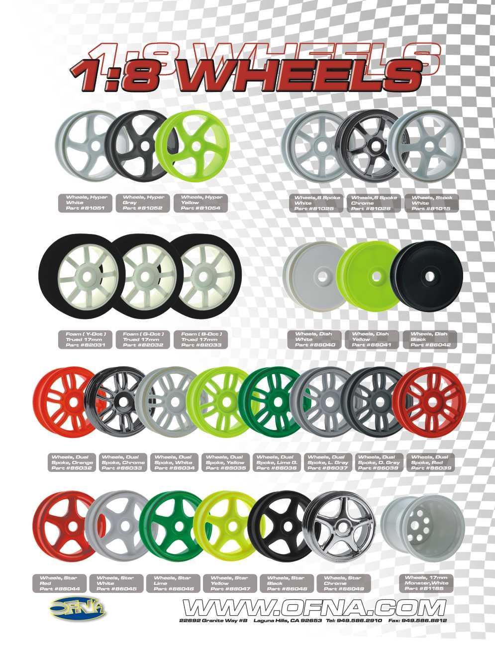
29 ASSEMBLY OF THE TIRES AND WHEELS * The tires might be different as picture shown Inner Sponge (Small) * Take off double side tape Chrome Wheel # Red # White # Lime # Yellow # Black # Chrome 17mm 5-Star Wheels, Two (2) Pairs per bag Inner Sponge (Large) * Use foam cement to glue together. Not CA Glue Slick Tires * Put the sponge on the middle of the wheel. # Slick Tire, No-belt # Slick Tire, Belted # Treaded Tire, No-belt # Treaded Tire, Belted *Put the tire into the groove of the wheel. # Pre-glued Set, Slick/White # Pre-glued Set, Tread/White # Pre-glued Set, Slick/Chrome Using 17mm 5-Star Spoke Wheels, pairs * Apply instant glue into the groove of the wheel. WE RECOMMEND CA GLUE FOR RUBBER TIRES. OFNA NUMBER: # SPECIAL CA GLUE INSTANT GLUE * Apply instant glue into the groove of the wheel. INSTANT GLUE YOUR KIT COMES WITH PRE-GLUED TIRES, BUT WHEN TIRES ARE WORN YOU MUST REPLACE THEM. MAKE TIRE AND WHEEL SET AS SHOWN Rear Hub Assembly Wheel Nut, Blue R Front Knuckle Arm Assembly Wheel Nut, Blue
30
 5. After the engine be started, remove the 1.2V glow plug starter.")
31 STARTING OF THE ENGINE WITHOUT PULL START How to start the engine: 1. Turn on transmitter and then receiver. 2. Fill fuel tank with fuel bottle. 3. Connect 1.2V glow plug starter. 4. Start engine with 12V starter or starter box ( Note the direction of the starter.) 5. After the engine be started, remove the 1.2V glow plug starter. * Follow the engine manufacturer instruction manuals regarding engine set-up, carburetor and maintenance. 1.2V Glow Plug Starter * Note the direction of the starter. Connect with 12V battery * To start the engine, use hand held starter motor or starter box. Rubber wheel turns engine flywheel. OFNA #10251 #10250 Starter Box 12V Starter


 at your local hobby supplier.")


 Allow the paint to dry for at least an hour!")


32 PAINTING TIPS For BUGGY STEP 1 Wash the inside of the body with detergent to STEP 2 Tools required are: Curved scissor, hobby knife STEP 3 remove any oil and dirt. Dry with lint free towel and a quality masking tape. These can be purchase or a hair dryer. (Keep your hand clean.) at your local hobby supplier. Use the curved scissors to trim the body to the guide lines provided on you body shell. STEP 4 Use masking tape on the inside of the body to STEP 5 Paint the inside of the body! STEP 6 mask out your design and windows prior to Use a spray color suitable for polycarbonate. painting. Press down the edges! (Paint the darkest color first.) Allow the paint to dry for at least an hour! Remove the masking tape and protection film from the outside of the body. STER 7 Apply the decals to the outside of the body. We suggest use a hobby knife to cut them out. STEP 8 Use a hobby knife to cut holes for the fuel tank, STEP 9 engine and antenna tube. Make two 7mm holes for the body posts; one at the front and one at the rear. Drill two 7mm holes in nylon wing. Using the measurements provided in the instruction. Use the clip provided to secure the wing to the wing mount posts. STER 10 Mounting the body to the buggy using the body clips provided.

. When running car, adjust carb with 1/8 clockwise turns, slowly leaner, until the top speed good.")
33 ENGINE BREAK-IN AND TUNNING (BREAK-IN THE ENGINE BEFORE DRIVING THE CAR!) Choose a wide clear outdoor location with low dirt and dust. Set the car on box or holder with wheels off the ground. Turn on radio and car. Make sure throttle is at idle position. Fill fuel tank and set master engine needle. Prime fuel line and Heat glow plug before pull starting engine. When started, let engine fast idle for two tanks of fuel. OPTIONAL OFNA CAR STANDS WOOD BLOCK TUNING AFTER BREAK-IN Close master needle by turning clockwise until it stops. Then open needle by turning counterclockwise 3 turns (rich setting). When running car, adjust carb with 1/8 clockwise turns, slowly leaner, until the top speed good. Check engine temp, if possible, for no more 250 degrees. Adjust low end needle for best throttle response. Use only small turns. From idle, give it full throttle, if throttle is slow lean out needle until good. Adjust barrel stop so it will not close, accept for a small gap. This gap will be the idle setting. You will notice the idle will increase with a wide gap. Idle adjuster screw & Barrel Stop Lean Rich
34 1:1 SCREW SHEET 3 x 5mm Cap 3 x 10mm Cap 3 x 12mm Cap 3 x 15mm Cap 3 x 20mm Cap 3 X 25mm Cap 3 x 5mm Tapping 3 x 8mm Tapping 3 x 10mm Tapping 3 x 12mm Tapping 3 x 15mm Tapping 3 x 20mm Tapping 3 x 25mm Tapping 3 x Set 3 x 5mm Set 3 x 8mm Set 3 x 10mm Set 3 x 15mm Set 4 x 4mm Set 4 x 10 mm Set 5 x 5mm Set 2 x 4mm 2 x 5mm 2 x 6mm 2 x 8mm screw 2 x 10mm 2 x 25mm M3 Nut M4 Nut M3 Nylon Locknut M4 Nylon Kocknut M3 Flange Nut ( Steel ) 2 X 6mm Washer 2mm X 7mm Washer 3 X 8mm Washer 5 X 9mm Washer mm 5 X 10mm Washer 5 X 12mm Washer 3 x 10mm Flat Head Tapping 3 x 15mm Flate Head Tapping 3 x 20mm Flat Head Tapping 3 x 5 mm Flat Head 3 x 25mm Flat Head Tapping 3 x 10 mm Flat Head 3 x 15mm Flat Head 3 x 20mm Flat Head 4 x 10mm Tapping 3 x 25mm Flat Head 4 x 15mm Tapping 4 x 20 Tapping 4 x 25mm Tapping 4 x 15mm Tapping ( Small Head ) 3 x 5mm 3 x 10mm 3 x 15mm 3 x 20mm 3 x 30mm 4 x 6mm Flat Head 4 x 10mm Flat Head 4 x 15mm Flat Head 4 x 20 mm Flat Head 4 x 10mm Flat Head Tapping 4 x 16mm Flat Head Tapping 4 x 20mm Flat Head Tapping 3 x 30mm Pin ( Black ) 3 x 30mm Pin ( Silver ) 2mm E-Ring 2.5mm E-Ring 3 mm E-Ring 4 mm E-Ring 5 mm E-Ring 6 mm E-Ring 7 mm E-Ring
35
36 SETTING UP ADJUSTMENT OF THE CHASSIS CLEARANCE Use 2mm hex wrench to adjust 4x10mm set screw in front lower arm. (FRONT) Use 2mm hex wrench to adjust 4x10mm set screw in rear lower arm. (REAR) Place the model car on flat surface. Use 2mm hex wrench to adjustment the chassis to it's minimum clearance. We Suggest: 10mm in front and rear. Adjustment of the right and left-side are the same height. SET-UP OF THE FRONT WIDTH * Use a 2.5mm hex wrench to adjust length of the front lower steering ball will make the front become width or narrow. Adjust from the lower steering ball. (FRONT) ADJUSTMENT OF THE FRONT AND REAR CAMBER (Positive) + Adjust from the upper steering ball of the front knuckle arm. 0 - (Negative) (FRONT) 154mm Center FRONT TOE-IN AND TOE-OUT SETTING The rear camber adjustment can made by moving the turnbuckle rod on the upper arms, clockwise or anticlockwise. Toe Out 0 Toe-In (Positive) (Negative) (REAR) Adjust the length of the front steering rod to change the toe angle. Making the steering longer will make the front tires become toe-in. Response will be slower. Making the steering rod shorter will make the front tire became tor-out. Response will be quicker. Steering Rod
37 OPTION PARTS OF THE 2-SPEED TRANSMISSION 4X4mm SET SCREW St Spur Gear Holder (One-Way) 1St Spur Gear (49T.48T.47T) Clutch Cam Counter - Clockwise One-way Center Gear Shaft Clutch Cam Alum. Nut Counter - Clockwise Nut nd Spur gear Holder (Ball bearing Type) mm E-Ring 2nd Spur Gear (46T.45T.44T) nd Spur gear Holder (Ball bearing Type) Optional 2-speed Transmission kit For super fast, add a 2-speed transmission. #35001 Retail $ x10x Alum. Ring Cement T/17T Gear x10mm Ball bearing Clutch Bell (For 2 speed.) x10mm Ball bearing
38
39 35001 HN SPEED KITS, HODR, ULTRA'S, BLAZER, GTP, REV HN SPEED KIT, INFERNO (NOT MP5/ 6) HN SPEED KIT, INFERNO (NOT MP5/ 6) HN-294G GEARS, 2-SPEED SET, 13T/17T REV HN-220L BASE, CLUTCH BELL, SCREW-ON BASE REV C-11 BEARING, 5x10mm 2 PCS B-02 SHAFT, OFNA CARS, 2-SPEED REV B-0 SHAFT, KYOSHO 7.5, 2-SPEED REV B-0 SHAFT, MUGEN MBX, 2-SPEED REV HN-293A ALUM.HOLDER, 1ST GEAR, 2-SPEED REV HN-293B ALUM.HOLDER, 2ND GEAR, 2-SPEED REV HN-293C CLUTCH CAM DISC., 2-SPEED REV HN-293D ALUM. NUT, CCW NUT, LARGE, 2-SPEED REV HN-293E E-CLIP, 18mm HN-293F BEARING, 8x12 FLANGE, 2 PCS HN-293G ALUM. SPACER, 8x10mm HN-294H GEARS, 2-SPEED SET, 14T/18T REV HN-294I GEARS, 2-SPEED SET, 15T/19T REV HN-294A SPUR GEAR, 49T, 2-SPEED REV HN-294D SPUR GEAR, 46T, 2-SPEED REV HN-294B SPUR GEAR, 48T, 2-SPEED REV HN-294C SPUR GEAR, 47T, 2-SPEED REV HN-294E SPUR GEAR, 45T, 2-SPEED REV HN-294F SPUR GEAR, 44T, 2-SPEED REV
40 INSTRUCTIONS # /8 SCALE 2-SPEED TRANSMISSION SET (Shoes Type) * This professional two speed transmission is only for ULTRA GT series and ULTRA GTP series kits. OFNA RACING INSTALLATION SHEETS # /8 SCALE 2-SPEED TRANSMISSION SET (Shoes Type) Clockwise 2nd Spur Gear (46T.45T.44T) *2nd gear Adjustment Hole. 1st Spur Gear (49T.48T.47T) # nd Spur gear Clutch Bell, rev 3 (Ball bearing Type) # st Spur Gear Holder (One-Way bearing installed) 49 #35228 Alum. Nut (Counter clockwise) #35219 Alum. Nut (Clockwise) # x 12mm Flange Ball earing * Push down firmly keeping the gear straight. *NB, this mark is for the Counter Clockwise nut. Counter Clockwise # x 12mm Flange Ball bearing * Push bearing into the gear holder. 5 X 5mm Set M6x6mm Set * Find a flat surface and use 500 grit sand paper to ensure the shoes are flat. #35235 Clutch Shoe Carrier #35222 Center Gear Shaft * Note: Put the small ring on the short side. * Put the 2 speed carrier in the "D" cut M3x15mm Hex Spring mm Ball Nylon Nut Sand Paper * Important Pre-Setup Slightly sand! * M3x15mm screw in until spring compresses, do not crush! Back screw off 5 turns. Shoe assembly should set into alum. Clutch holder. Short Not less than 7mm. Long mm ud Gear Clutch Shoes Nylon Nut mm Ball Spring M3x15mm Hex M3x15 * Tighten Set s M6x6mm slightly to allow pressure from ball to hold center cam. Do not over tighten. Adjust both screws for an even amount of pressure. M6x6 Set s Clutch Shoes after assembly M6x6mm Set 6 2 SPEED TRANSMISSION AFTER ASSEMBLY nd Gear Assembly 1st Gear Assembly # x10x1.5mm Alum. Ring
41 7 ASSEMBLY OF THE 2 SPEED TRANSMISSION INTO CENTER MOUNT (Use the parts that come with your kit.) #30170 Brake Joint *Use the ball bearings #30621 that come with your car. 7 x 19x 5mm Ball bearings # x 19x 5mm Ball bearings Brake Joint Cement 5 X 5mm Set #30200 Center Diff. Mount (Rear) * Large gear to front. #30200 Center Diff. Mount (Front) Cement 5 X 5mm Set 8 9 #33171 Brake Lever 3 x Set Cement 3 x 10mm Tapping *Use the parts comes with your kit. # Center Plate #30211 Plastic Pushing #30210 Brake Cam Leave 0.5 mm #30180 Brake Pads ASSEMBLY OF THE CLUTCH BELL #35221 Clutch Bell Base (For 2 speed.) Cement # T/17T Gear To Front #30190 Brake Disc 3 x12mm # x10mm Ball bearing * gear stack onto base # x10mm Ball bearing
42 * Adjust the engine before adjusting the clutch shift timing. Adjust the engine as per engine instruction manual. * Two steps to adjust the shoes and shift timing. 6x6mm Set AIR GAP SETTING ADJUSTING THE SHIFT POINT 2mm and 2.5mm Allen Wrench * Use a 2mm and 2.5mm allen wrench to set the clutch shoes. Clockwise (Tighten) 1. Use a 2.5 mm allen wrench to adjust shoe assembly air gap. Tighten Set s, M6x6mm, to adjust the air gap between the shoe assembly and clutch bell wall. Adjust both screws for an even amount of gap of about 1mm. Counter-clockwise (Loosen) M3x15 Hex 6x6mm Set M3x15 Hex SHIFT TIMING SETTING 2. Use a 2mm allen wrench to adjust the shift timing. Turn, M3x15mm, screws IN until spring compresses, do not crush! Back off screw 5 turns, this is a good place to start. When adjusting shift timing, always turn each screw the same number turns. Adjustment thru this hole. 1. Once the engine adjustments have been completed, proceed to the adjustment of the clutch shift timing. (Using a 2mm allen wrench to adjust the clutch shoes.) Note: Clockwise Shift timing will become slower. Counter Clockwise---Shift timing will become quicker. To Front 2. Adjust the clutch shift timing for your track conditions. As you tighten (Clockwise) the 3x15mm hex screw, the shift timing will become slower. As you loosen (Counter Clockwise ) the 3x15mm hex screw, the shift timing will become quicker. 3. Set the shift timing to the track conditions while the car is running. 2 SPEED GEAR RATIO COMBINATIONS The # speed transmission has a smoother gear change and is less aggressive on the 2nd gear. We offer many different pinion and spur gear combinations which can be used for different tracks. IMPORTANT: The sum of the spur gear and clutch gear for1st gear must be equal the sum of the spur gear and clutch gear for 2nd gear be equal. Example: 1st gear 45+13=58 2nd gear 41+17=58 Must be equal ( STANDARD) SPUR GEAR CLUTCH GEAR (4 tooth difference) 49T/45T 13T/17T 14T/18T 15T/19T 48T/44T 47T/43T 16T/20T Torque Top Speed Short Track Long Track 2 SPEED OPTION PARTS 2 SPEED SPARE PARTS SPUR GEAR(1st): SPUR GEAR(2nd): CLUTCH GEAR: USA Parts No. No T Spur Gear (STD) No No USA Parts No. No Description 48T Spur Gear 47T Spur Gear 46T Spur Gear No T Spur Gear (STD) No USA Parts No. Description 44T Spur Gear No T/17T Gear (STD) No No OFNA Racing-USA Tel: Fax: Description 14T/18T Gear 15T/19T Gear Made In Taiwan USA Parts No. Description st Spur Gear Holder Alum. Nut (Counter-Clockwise) x12mm Flange Ball bearing Center Shaft x10x4mm Ball bearing Clutch Bell Base T Spur Gear (1st) T Spur Gear(2nd) nd Spur Gear Clutch Bell Clutch Shoe Carries Alum. Nut (Clockwise) nd Clutch Shoes Misc Parts Spring 4mm Ball x6mm Set 3x15mm Hex x10x1.5mm Alum. Ring
43 OPTIONAL Rear Pivot Ball Suspension Kit For "ULTRA GTP" #31300 This rear pivot ball kit is suitable for those who already have "ULTRA GTP" car kit. ASSEMBLY OF THE NEW FRONT LOWER ARM * Follow these instructions to assemble this kit. Assembly of the right and left hand side are the same. 1 REPLACE THE OLD FRONT LOWER ARMS WITH 2 REMOVE THE FRONT STABILIZER THE NEW ARMS. AND PARTS BAR FROM YOUR CAR x10mm Set R E-Ring Front Lower Arm * A 4 x 10mm set screw is used to adjust the ride height. R * Insert drive shaft before assembly x80mm Lower Arm Shaft 4 * Approx. 3 ASSEMBLY OF THE UPPER ARM SHAFT AND THE CASTER ADJUSTER Caster Angle Adjuster INSERT THE NEW FRONT LOWER ARM SHAFT E-Ring R Upper arm Shaft E-Ring ASSEMBLY OF THE ANTI-ROLL BAR * Builds two sets of anti-roll bars for the front and rear Anti-Roll Bar Mount (Left) Anti-Roll Bar Anti-Roll Bar Mount (Right) 3x Set Anti-Roll Bar 3x Set * Insert into cap.
44 ASSEMBLY OF THE REAR HUB * Use the ball bearings and rear drive shaft from your car kit Rear Hub x16mm Ball bearings Rear Wheel Shaft * Make sure the pivot ball move smooth. Assembly of the right and left hand side are the same. *Use the 4mm set screw from your kit mm Set mm Alum. Hex Nut mm Pivot Ball Rear Lower Arm x16mm Ball bearings 5mm Hex Wrench Ball Washer * A 4 x 10mm set screw is used to adjust the ride height. * Approx. ASSEMBLY OF THE SUSPENSION ARMS ONTO REAR GEAR BOX * Use the parts that come with your kit E-Ring Arm Shaft * Remove the stabilizer and parts from your car. Assembly of the right and left hand side are the same. 1 Degree 1.5 Degree * Insert rear drive shaft before assembly Rear Drive Shaft E-Ring Fig Drive Pin Rear Wheel Toe-in Adjuster * Set triangle marks in the direction shown in Fig x5mm Set * Do not r tighten 5x5mm set screw over tighten. Plastic Washer (Use 2 pcs) Nylon Lock Nut E-Ring Upper Arm *Use the upper arm and screw from your car. Nylon Lock Nut x 25mm Cap x 25mm Cap
45 ASSEMBLY OF THE FRONT ANTI-ROLL BAR ( FRONT) Anti-Roll Bar Adjuster R Anti-Roll Bar Adjuster 3x16mm *Turn the anti-roll bar adjuster keeping both side at the same angle. * Keep the ball of the anti-roll bar central. ( REAR) Turn Turn Changing the angle of the anti-roll bar will change the strength of the arms Anti-Roll Bar Adjuster Anti-roll strength became weaker Turn Anti-roll strength became stronger Anti-Roll Bar Adjuster 3x16mm REAR WIDTH SETTING ASSEMBLE THE FRONT AND REAR GEAR BOX ONTO YOUR CAR AS USUAL. SETTING GUIDE REAR CAMBER SETTING Adjust A and B to the same length Adjusting B longer will make the rear tires toe-in (Positive). Adjusting A longer will make the rear tires toe-out (Negative). The rear camber adjustment can be make by changing the length of the upper rod. Making the upper rod longer will make the camber positive. Making the upper rod shorter will make the camber negative. 0 Upper Rod A B A B * Use a 2.5mm hex wrench to adjust the rear track width. C C.L C' PARTS LIST Item No. Description Qty Anti-Roll Bar 1 set x80mm Arm Shaft 2 pcs Anti Roll Bar Mount / Adjuster 1 set Front Lower Arm 1 set Rear Lower Arm 1 set Item No. Description Qty Rear Hub (Pivot Ball Type) 2 pcs Ball Washer 4 pcs Anti Roll Bar Mount / Adjuster 1 set Alum. Hex Nut 4 pcs Pivot Ball 2 pcs.
RTR Instruction Manual
 RTR Instruction Manual OFNA RACING 22692 Granite Way, Ste. B Laguna Hills, CA. 92653 PRE-ASSEMBLED ASSEMBLED CHASSIS WITH RADIO AND ENGINE REQUIRED FOR OPERATION THINGS NEEDED You will need to buy a few
RTR Instruction Manual
 OFNA Racing 22692 Granite Way, Ste. B Laguna Hills, Ca. 92653 (949) 586-2910 Www.ofna.com RTR Instruction Manual PURE COMPETITION... PRE-ASSEMBLED ASSEMBLED CHASSIS WITH RADIO AND ENGINE REQUIRED FOR OPERATION
1:8 SCALE GAS POWERED OFF-ROAD BUGGY
 Instruction RTR Manual 1:8 SCALE GAS POWERED OFF-ROAD BUGGY PLEASE READ INSTRUCTIONS CAREFULLY BEFORE ASSEMBLING THIS MODEL. KEEP THIS MANUAL FOR PARTS NUMBERS WHEN ORDERING. REQUIRED FOR OPERATION THINGS
RTR Instruction Manual
 RTR Instruction Manual OFNA RACING 22692 Granite Way, Ste. B Laguna Hills, CA. 92653 PRE-ASSEMBLED ASSEMBLED CHASSIS WITH RADIO AND ENGINE REQUIRED FOR OPERATION THINGS NEEDED You will need to buy a few
PLEASE READ INSTRUCTIONS CAREFULLY BEFORE ASSEMBLING THIS MODEL. KEEP THIS MANUAL FOR PARTS NUMBERS WHEN ORDERING.
 INSTRUCTION MANUAL PLEASE READ INSTRUCTIONS CAREFULLY BEFORE ASSEMBLING THIS MODEL. KEEP THIS MANUAL FOR PARTS NUMBERS WHEN ORDERING. REQUIRED FOR OPERATION THINGS NEEDED You will need to buy a few items
RTR KITS - REQUIRED FOR OPERATION
 Strong Front and Rear chassis braces. Tuned Polished Dual Chamber racing pipe. Unique adjustable chassis width of 310mm or 330mm. High performance.26 engine with Shaft Start Motor handle. Full race Offset
PLEASE READ INSTRUCTIONS CAREFULLY BEFORE ASSEMBLING THIS MODEL. KEEP THIS MANUAL FOR PARTS NUMBERS WHEN ORDERING.
 INSTRUCTION MANUAL PLEASE READ INSTRUCTIONS CAREFULLY BEFORE ASSEMBLING THIS MODEL. KEEP THIS MANUAL FOR PARTS NUMBERS WHEN ORDERING. REQUIRED FOR OPERATION THINGS NEEDED You will need to buy a few items
1:8 SCALE GAS POWERED OFF-ROAD BUGGY
 SUPPLEMENTAL MANUAL TQ Sport 1:8 SCALE GAS POWERED OFF-ROAD BUGGY INSTRUCTION MANUAL PLEASE READ INSTRUCTIONS CAREFULLY BEFORE ASSEMBLING THIS MODEL. KEEP THIS MANUAL FOR PARTS NUMBERS WHEN ORDERING. SPECIFICATION
1/8 Scale Gas Powered Off-Road Buggy
 1/8 Scale Gas Powered Off-oad Buggy The body shown is slightly different in the U.S. kits PUE COMPETITION... INSTUCTION MANUAL OFNA acing 22692 Granite Way, Ste. B Laguna Hills, Ca. 92653 (949) 586-2910
1:8 SCALE GAS POWERED OFF-ROAD BUGGY BLACK EDITION WITH 14MM SHOCKS
 SUPPLEMENTAL MANUAL 1:8 SCALE GAS POWERED OFF-ROAD BUGGY BLACK EDITION WITH 14MM SHOCKS TQ Sport INSTRUCTION MANUAL PLEASE READ INSTRUCTIONS CAREFULLY BEFORE ASSEMBLING THIS MODEL. KEEP THIS MANUAL FOR
HI PerFORMANCE 1/8 OFF-ROAD NITRO BUGGY. Instruction manual OFNA 7 VANDERBILT, IRVINE, CA PH. (949)
") HI PerFORMANCE 1/8 OFF-ROAD NITRO BUGGY. Instruction manual OFNA 7 VANDERBILT, IRVINE, CA 92618 PH. (949) 586-2910 THINGS NEEDED RTR KITS - REQUIRED FOR OPERATION You will need to buy a few items to start
HI PerFORMANCE 1/8 OFF-ROAD NITRO BUGGY. Instruction manual OFNA 7 VANDERBILT, IRVINE, CA 92618 PH. (949) 586-2910 THINGS NEEDED RTR KITS - REQUIRED FOR OPERATION You will need to buy a few items to start
ASSEMBLY OF THE FRONT AND REAR BALL DIFF. Builds two differentials for front and rear
 1 ASSEMBLY OF THE FRONT AND REAR BALL DIFF. 37145 40060 40060 2.6mm Nylon Nut 37110 35958 37132 2.6x6x1mm Washer 37148 Apply Grease 37120 (12 Pcs) Builds two differentials for front and rear. 38288 35958
X 3mm Flat Head Screw. Adjustment Hole x15x4mm Ball bearing. M2x10mm Hex Screw. Spring. Clutch Shoe. Ball.
 INSTRUCTIONS #35017 NITRO OB-4 1/10 SCALE 2-SPEED TRANSMISSION SET (Shoe Type) * This professional two speed transmission is only for Nitro OB-4 1/10 Scale OB4 Gas Car Kits. Nitro Ob4 ASSEMBLY OF THE TWO
MODEL SHOWN MAY BE PROTOTYPE AND MAY VERY SLIGHTLY FROM KIT. SPECIFICATIONS ARE SUBJECT TO CHANGE WITHOUT PRIOR NOTICE.
 MODEL SHOWN MAY BE PROTOTYPE AND MAY VERY SLIGHTLY FROM KIT. SPECIFICATIONS ARE SUBJECT TO CHANGE WITHOUT PRIOR NOTICE. OFNA RACING 7 VANDERBILT IRVINE, CA 92618 PHONE: (949) 586-2910 FAX: (949) 586-8812
MUST READ THIS BEFORE RUNNING
 BLANK MUST READ THIS BEFORE RUNNING Running a nitro kit is fun and easy, but to make this a safe and good experience you must observe a few rules. This kit is extremely fast, easily over 40MPH, and can
DIFFERENTIAL STEERING RACK
 BAG-A DIFFERENTIAL (2 Sets) +Driver Cap Screw Diff Ball Nylon Nut Thrust Washer Thrust Ball Diff Joint Cup A Allen Wrench 850 Bearing Diff Ring Diff Spring Nylon Nut 850 Bearing Diff Ring Diff Ball Ball
New Generation Rear Wheel Drive
 New Generation Rear Wheel Drive ABC HOBBY ORIGINAL RADIO CONTROL CAR Instruction Manual Study the instructions thoroughly before assembly. REAR 2 WHEEL DRIVE REAR MOUNTED MOTOR BELT DRIVE DOUBLE DECK CHASSIS
7207 FRONT BULKHEAD, nylon FRONT BULKHEAD ALUMINUM SUPPORT HINGE PIN, inner, with clips, 1.675" pr GT RACING FRONT
 RC10GT & RTR GT MC 9 McCOY GLOW PLUG 1 3.9 2661 CLUTCH NUT CLIPS 6.7 3216 WASHER, #4 12 1.00 3719 NYLON WIRE TIES, 6" heavy duty 12 2.00 3720 NYLON TIES, 8", light duty for receiver 12 2.00 3721 SELF-TAPPING
ABC HOBBY ORIGINAL RADIO CONTROL CAR
 ABC HOBBY ORIGINAL RADIO CONTROL CAR Instruction Manual Study the instructions thoroughly before assembly. FRONT WHEEL DRIVE NEW STYLE STRUT SUSPENSION BATHTUB CHASSIS 4 BEVEL GEAR DIFFERENTIAL FULL ADJUSTABLE
En Instruction Manual De Bauanleitung. Fr Manuel de montage
 En Instruction Manual De Bauanleitung Fr Manuel de montage RTR Trophy Truggy Flux En De Fr Jp Vol.1 101875 Chassis Maintenance Chassis Wartung Entretien du châssis シャーシのメンテナンス 1 Gear Differential 101087
TP02C. 1:10 Scale Radio Controlled Electric Powered 2WD Racing Buggy. Dimensions. Length 410mm Width 250mm Height 150mm
 TP02C 1:10 Scale Radio Controlled Electric Powered 2WD Racing Buggy Dimensions Length 410mm Width 250mm Height 150mm Transmitter Preparation Power Switch Antenna 27MHzTransmitter Crystal T 27MHz ON Extend
2103 NITRO RAIL DRAGSTER KIT
 203 NITRO RAIL DRAGSTER KIT THANKS FOR BUYING RJ SPEED S NITRO DRAG KIT. IT IS A LITEWEIGHT CAR MADE FOR STRAIGHT LINE DRAG RACING AND CAN BE BROKEN IF RUN INTO SOLID OBJECTS AT HIGH SPEED. YOU WILL NEED
Bag 1. Bag 1. Center Pivot. Center Pivot
 8 00734 01901 5 Center Pivot Bag 1 3374 - Center Pivot Socket 4019 - Alum Pivot ball 3254-2-56 Button Head *Note - Sometimes it is helpful to slightly over-tighten the top clamp screws, then work the ball
2101 NITRO PRO STOCK DRAG KIT 2104 NITRO PRO MOD DRAG KIT
 2101 NITRO PRO STOCK DRAG KIT 2104 NITRO PRO MOD DRAG KIT THANKS FOR BUYING RJ SPEED S NITRO DRAG KIT. IT IS A LITEWEIGHT CAR MADE FOR STRAIGHT LINE DRAG RACING AND CAN BE BROKEN IF RUN INTO SOLID OBJECTS
PARTS CATALOG FOR MTA-4 MONSTER TRUCK No.6218-F 1/8 4WD NITRO MONSTER TRUCK
 PARTS CATALOG FOR MTA-4 MONSTER TRUCK No.6218-F 1/8 4WD NITRO MONSTER TRUCK 1/8 4WD NITRO MONSTER TRUCK Features High power and reliable.21 size engine that has two different starting methods (pull start
RJS2020 SPORT 3.2 1/10 PAN CAR KIT LESS ELECTRICS
 RJS2020 SPORT 3.2 1/10 PAN CAR KIT LESS ELECTRICS THANKS FOR BUYING THE RJ SPEED 1/10 SPORT 3.2 KIT. THE ASSEMBLY WILL NOT BE DIFFICULT IF YOU READ THE TEXT, LOOK AT THE PICTURES, AND THE EXPLODED VIEW
ASSOCIATED 1:10 SCALE GT MANUAL
 ASSOCIATED 0 SCALE GT MANUAL INSTRUCTION MANUAL FOR THE RC10GT GAS TRUCKS #7060, 7061, 7067, 7068, & 7090 ASSOCIATED S RC10GT-- 3 TIMES NORRCA WORLD CUP CHAMPION! 200 Thank you for purchasing this Team
 29066 29156 29153 29154 29003 29157 29003 29157 29153 29153 29157 29155 29153 29066 29157 29003 29157 29066 29003 29158 29153 Oil No. 5000 29154 29003 29003 29157 29153 29046 29153 29157 29153 29157 29046
Assembly Manual. 1/10th Formula 1 Car
 Assembly Manual 1/10th Formula 1 Car Center Pivot Bag 1 3374 - Center Pivot Socket 40194 - Hard Anodized Alum Pivot ball 3254-2-56 *Note - Sometimes it is helpful to slightly over-tighten the top clamp
Make these adjustments before racing
 FINAL ADJUSTMENTS ADJUSTING CAMBER To set the camber we recommend using our supplied #1719 camber/rear toe-in gauge. When adjusting camber you need to have the car ready to run with no body. Make these
=Apply Thread lock adhesive. =Apply CA Glue =Apply Grease NOTE : BAG 01 BAG 01 BAG 01. R Front One Way Cup (2) R Front One Way
 R Front One Way") NOTE : =Apply Thread lock adhesive R80059 One Way Cup () R8009 One Way R80 Pulley Set- R80004 Alu-Bulkhead-L BAG 0 =Apply Glue =Apply Grease R8000 Upper Arm Bracket Base R8004 One Way Plastic Shims ()
NOTE : =Apply Thread lock adhesive R80059 One Way Cup () R8009 One Way R80 Pulley Set- R80004 Alu-Bulkhead-L BAG 0 =Apply Glue =Apply Grease R8000 Upper Arm Bracket Base R8004 One Way Plastic Shims ()
=Apply Thread lock adhesive. =Apply CA Glue =Apply Grease NOTE : BAG 01 BAG 01 BAG 01
 NOTE : =Apply Thread lock adhesive R80059 One Way Cup R8009 One Way R80 Pulley Set- R80004 Alu-Bulkhead-L BAG 0 =Apply Glue =Apply Grease R8000 Upper Arm Bracket Base R8004 One Way Plastic Shims () R80005
1/10 Scale 4WD 200mm Gas Power Touring Car
 1/10 Scale 4WD 200 Gas Power Touring Car STS PRO 10 Instruction Manual DIMENSIONS Length: 390 Width: 200 Height: 120 Weight (ready to run): About 1800g DRIVETRAIN Type: 3-belt 4WD Transmission: 2-speed
OWNER'S MANUAL Magnolia Ave., Chino, CA phone: (909) fax: (909)
 fax: (909)") OWNER'S MANUAL Carefully read through all instructions to familiarize yourself with the parts, construction techniques, and tuning tips outlined in this manual. Being able to grasp the overall design of
OWNER'S MANUAL Carefully read through all instructions to familiarize yourself with the parts, construction techniques, and tuning tips outlined in this manual. Being able to grasp the overall design of
PARTS CATALOG FOR SST STADIUM TRUCK RTR CAR
 PARTS CATALOG FOR SST STADIUM TRUCK RTR CAR No.6714-F 1/10 4WD NITRO POWERED STADIUM TRUCK NITRO POWERED STADIUM TRUCK No.6714-F 1/10 4WD NITRO POWERED STADIUM TRUCK Features: 100% Factory assembled 2-Channel
Sportwerks Raven RTR Assembly and Operation Manual
 Sportwerks Raven RTR Assembly and Operation Manual Specifications: Scale.............. 1/10 Length............. 16 in (406mm) Front Track.......... 12.75 in (324mm) Rear Track.......... 12.5 in (318mm)
OWNER'S MANUAL 2000 & ROAR National Champion
 2000 & 2001 ROAR National Champion OWNER'S MANUAL Carefully read through all instructions to familiarize yourself with the parts, construction techniques, and tuning tips outlined in this manual. Being
XRAY KITS M18 M18T M18MT PARTS NT18 NT18T NT18MT PARTS. o = option part x = standard included / fits
 PRO LiPo PRO USE THE DROP MENU TO FILTER THE SELECTION XRAY KITS o = option part x = standard included / fits 38 0000 XRAY - 4WD SHAFT DRIVE 1/18 MICRO CAR 38 0003 XRAY PRO LiPo - 4WD SHAFT DRIVE 1/18
General Building Tips: A Good Dealer Is Extremely Important!! 1 Additional Items Needed For Operation. Tools Supplied
 Owner s Manual Thank you for choosing the Team Magic E4JR. The E4JR includes a large selection of the important specialty parts when compared to the previous versions. Before you start building your new
Rustler 4X4 (Model ) Parts List
 Parts List") Parts shown in bold are optional accessories. Part categories and individual part listings are arranged alphabetically. Rustler 4X4 (Model 67064-1) Parts List Bearings & Bushings 4607 Ball bearings (5x11x4mm)
Parts shown in bold are optional accessories. Part categories and individual part listings are arranged alphabetically. Rustler 4X4 (Model 67064-1) Parts List Bearings & Bushings 4607 Ball bearings (5x11x4mm)
1/8 RG PD1871 TRANS CASE/BULK HEAD SET,S3 PD1875 UNIV. REBUILD KIT,S3 PD1876 CLUTCH SHOE (3), 1/8 PD1877 FR SHOCK SET(2),S3
, 1/8 PD1877 FR SHOCK SET(2),S3") 9279W AIR FILTER, 1/8 WHITE AN0747 FOAM FILTER (3), 1/8 PD1052 REAR BODY MOUNT PD1211 BODY SUPPORT SET 1/8 RG PD1242 1/8 CLUTCH BELL, 26MM 13T PD1795 TIRE W/FOAM RALLY, 1/8 PD1800 DIFFERENTIAL SET CENTER,
9279W AIR FILTER, 1/8 WHITE AN0747 FOAM FILTER (3), 1/8 PD1052 REAR BODY MOUNT PD1211 BODY SUPPORT SET 1/8 RG PD1242 1/8 CLUTCH BELL, 26MM 13T PD1795 TIRE W/FOAM RALLY, 1/8 PD1800 DIFFERENTIAL SET CENTER,
1:8 SCALE CATALOG 1:8 GAS KITS RC500 FRONT END BODY ACCESSORIES
 1:8 SCALE CATALOG Stock is extremely limited. Parts listing as of 7/2001. Sale prices apply to orders direct from Associated only. Items available while supplies last. Items marked Not available or are
WARNING! Hard anodized, PTFE-coated shocks. Hard anodized, PTFE-coated MIP CVD's.
 200 Thank you for purchasing this Team Associated product. This manual contains steps and instructions you will use to set up your gas truck. Please read this entire manual before attempting to start your
along with standard XT2 Instruction Manual and also XT2 18 Supplementary Sheet.
 Use this XT2 Dirt Conversion Supplementary Sheet along with standard XT2 Instruction Manual and also XT2 18 Supplementary Sheet. Parts included in Bag 8: 303141 SHIM 3x5x1.0MM (10) 322111 XT2 COMPOSITE
INFINITY 1/8 ONROAD KIT SPARE & OPTIONAL PARTS FRONT BODY MOUNT PLATE FRONT SUSPENSION ARM REAR UPPER ARM HOLDER SET SERVO SAVER SET FRONT UPRIGHT
 Tabella 1 Code CM-00001 Code R0001 R0002 R0003 R0004 R0005 R0006 R0007 R0008 R0009 R0010 R0011 R0012 R0013 R0014 R0015 R0016 R0017 R0018 R0019 R0020 R0021 R0022 R0023 R0024 R0025 R0026 R0027 R0028 R0029
E Thank you for purchasing VBC Racing product. COMPETITION GRADE HIGH PERFORMANCE RADIO CONTROL RACING CAR CHASSIS KIT INSTRUCTIONS MANUAL
 COMPETITION GRADE HIGH PERFORMANCE RADIO CONTROL RACING CAR CHASSIS KIT 1/10 SCALE ELECTRIC COMPETITION FORMULA CAR KIT INSTRUCTIONS MANUAL E Thank you for purchasing VBC Racing product. Things that we
INSTRUCTIONS MANUAL COMPETITION GRADE HIGH PERFORMANCE RADIO CONTROL RACING CAR CHASSIS KIT 1/12 SCALE ELECTRIC COMPETITION CAR KIT
 COMPETITION GRADE HIGH PERFORMANCE RADIO CONTROL RACING CAR CHASSIS KIT 1/12 SCALE ELECTRIC COMPETITION CAR KIT INSTRUCTIONS MANUAL E Thank you for purchasing VBC Racing product. Things that we should
This radio controlled racing car is not a toy! This high-performance R/C model is recommended for ages 14 and older.
 / 0 SCALE RADIO CONTROLLED GAS POWERED RACING TOURING CAR Width/98 mm (7.8") Height/0 mm (.") Track: 7 mm (6.8") Length/380 mm (5.0") Wheelbase/60 mm (0.") Gear Ratio/Low 7.55:/High 5.8: Ground Clearance
PREBUIL UILT ASSEMBLY AND OPERATION MANUAL
 PREBUIL UILT Length: 15.2" [385mm] Width: 13" [330mm] Height: 5.8" [147mm] Weight: 3.3 lb [1500g] Wheelbase: 11.6" [295mm] Technical Support Information For technical assistance, contact: DuraTrax Product
:: Additional Features Your new TC6 comes unassembled and requires the following items for completion. (refer to catalog section for suggestions):
:") 8/10 2 :: Introduction Thank you for purchasing this Team Associated product. This assembly manual contains instructions and tips for building and maintaining your new RC10TC6. Please take a moment to
8/10 2 :: Introduction Thank you for purchasing this Team Associated product. This assembly manual contains instructions and tips for building and maintaining your new RC10TC6. Please take a moment to
Assembly Manual. 1/10th World GT car
 Assembly Manual 1/10th World GT car Center Pivot Bag 1 3374 - Center Pivot Socket 40194 - Hard Anodized Alum Pivot ball 3254-2-56 Button Head *Note - Sometimes it is helpful to slightly over-tighten the
RJS2021 LTO SPORT OVAL RACER LESS ELECTRICS
 RJS2021 LTO SPORT OVAL RACER LESS ELECTRICS THANKS FOR BUYING THE RJ SPEED 1/10 LTO SPORT KIT FOR OVAL RACING. THE ASSEMBLY WILL NOT BE DIFFICULT IF YOU READ THE TEXT, LOOK AT THE PICTURES, AND THE EXPLODED
BIND ST-TRIM TH-TRIM ST-D/R
 4 4 4 4 BIND ST-TRIM TH-TRIM ST-D/R 1. Put the battery in the car. 2. Install the battery. 3. Turn on the transmitter. Connect firmly. 4. Turn on the electronic speed controller. ON OFF AX80084 UV Joint
Bigfoot (Model ) Parts List
 Parts List") Parts shown in bold are optional accessories. Part categories and individual part listings are arranged alphabetically. Bigfoot (Model 36084-1) Parts List Bearings & Bushings 4607 Ball bearings (5x11x4mm)
Parts shown in bold are optional accessories. Part categories and individual part listings are arranged alphabetically. Bigfoot (Model 36084-1) Parts List Bearings & Bushings 4607 Ball bearings (5x11x4mm)
 SUSPENSION PARTS LOSB2002 F/R Suspension Arms (pr)(lst2)... $10.00 LOSB2102 Steering Bell Cranks, Shafts, & Chassis Braces (LST/2)... $7.00 LOSB2104 Front Spindles & Carriers (LST2)... $7.00 LOSB2106 Rear
=Apply Thread lock adhesive. =Apply CA Glue =Apply Grease NOTE : BAG 01 BAG 01 BAG mm. When track High Traction or want to reduce steering
 NOTE : =Apply Thread lock adhesive R80059 One Way Cup () R8009 One Way R80 Pulley Set- R80004 Alu-Bulkhead-L BAG 0 CA GE =Apply CA Glue =Apply Grease R8000 Upper Arm Bracket Base R8004 One Way Plastic
Shown with optional GFR-1017R Body Posts. J & D Machine / Hyperdrive / MSA 3711 Moon Bend Rd. Chapel Hill, TN
 Shown with optional GFR-1017R Body Posts J & D Machine / Hyperdrive / MSA 3711 Moon Bend Rd. Chapel Hill, TN 37034 www.hyperdriveracing.com 1 You now own a state of the art 1/10 scale oval race car. The
PARTS CATALOG FOR UNO F1 RTR CAR
 PARTS CATALOG FOR UNO F1 RTR CAR No.6716 1/10th Scale 2WD NITRO POWERED 2WD FORMULAR 1 CAR F1 UNO SPORT ARTR/RTR PARTS LIST PD1657 FR HEX DRIVE BUSHING PD0140 CLUTCH SHOES PD0270 CLUTCH BELL BAG / 4T
J & D Machine / Hyperdrive / MSA 3711 Moon Bend Rd. Chapel Hill, TN 37034
 J & D Machine / Hyperdrive / MSA 3711 Moon Bend Rd. Chapel Hill, TN 37034 www.hyperdriveracing.com 1 You now own a state of the art 1/10 scale oval race car. The Hyperdrive Assault has gone through months
ASSOCIATED 1:10 SCALE ELECTRIC BUGGY INSTRUCTION MANUAL FOR THE TEAM ASSOCIATED RC10B Associated Electrics, Inc. RS-1
 ASSOCIATED 1:10 SCALE ELECTRIC BUGGY INSTRUCTION MANUAL FOR THE TEAM ASSOCIATED RC10B4 TT RS-1 2003-2006 Associated Electrics, Inc. FINAL ADJUSTMENTS RADIO ADJUSTMENTS Use the following
A7741 Truggy Wheel, Yellow
 STEP H-01 Tire Mounting BAG H 1 2 A7780B XTT Tire, Blue Truggy Foam Insert Only sold with Tires A7741 Truggy Wheel, Yellow STEP H-02 Tire Gluing The Tires need to be glued to the wheels. This can be done
MARACANA ASSEMBLY INSTRUCTION .40 ARF LOW WING TRAINER RADIO CONTROL MODEL. Every body can fly
 RADIO CONTROL MODEL ASSEMBLY INSTRUCTION MARACANA.40 ARF LOW WING TRAINER Every body can fly VQA085 EP GP You can use both Gas or Electric power Wingspan: 59in.(1520mm) Fuselage length: 48in.(1220mm) Engine:
2030 OUTLAW SPRINTER HARDWARE I.D. BUTTON HD. CAP SCREW BAG H1 CHASSIS KIT BAG H3 HARDWARE BAG L2 REAR AXLE PARTS BAG L4 FRONT TIRES
 THANKS FOR BUYING THE RJ SPEED OUTLAW SPRINTER KIT. IT IS COMPLETE LESS ELECTRICS, AND MADE FOR CARPET OR PAVEMENT RACING. IT REQUIRES A 540 OR 550 SIZE MOTOR, 4 OR 6 CELL BATTERY PACK, TWO CHANNEL RADIO
#0980 Intimidator 7 Direct Drive Racing Kit
 #0980 Intimidator 7 Direct Drive Racing Kit 1 Thank you for purchasing the Intimidator 7! Within this kit you will find a race winning car with over 30 years of Custom Works design and quality. The latest
BEFORE YOU START. XRAY Europe K Výstavisku 6992, Trenčín Slovakia EUROPE. XRAY USA RC America, 2030 Century Center Blvd #15 Irving, TX USA
 BEFORE YOU START The X12 is a high-quality, 1/12-pan car intended for persons aged 16 years and older with previous experience building and operating RC model racing cars. This is not a toy; it is a precision
Radio control model INSTRUCTION MANUAL PYLON RACING. Wingspan: 1148mm (45.2 ) Radio : 4 channels Engine : two-stroke
 Radio : 4 channels Engine : two-stroke") VQA038 VQA039 Radio control model INSTRUCTION MANUAL MAGIC PYLON RACING Wingspan: 1148mm (45.2 ) Radio : 4 channels Engine :.25 -.32 two-stroke WARNING! This radio control model is not a toy. If modified
VQA038 VQA039 Radio control model INSTRUCTION MANUAL MAGIC PYLON RACING Wingspan: 1148mm (45.2 ) Radio : 4 channels Engine :.25 -.32 two-stroke WARNING! This radio control model is not a toy. If modified
ASSEMBLY AND OPERATION MANUAL
 ASSEMBLY AND OPERATION MANUAL www.duratrax.com ITEMS INCLUDED The following items are included with your Vendetta Rally. Chassis Transmitter Body Decal Sheet Instruction Manual Exploded View/Parts Listing
carbon fiber before assembly. Sand glue to the edges and
 chassis and carbon fiber give you a before assembly. Sand glue to the edges and 5 BAG MARKED CA BAG MARKED M3x6 Flathead 4 03 4 05 BAG MARKED 2 10 13 Installing Steering System Shock Assembly M4x28
PARTS LIST FOR ITEM 43511
 PARTS LIST FOR ITEM 43511 1/10 SCALE FACTORY ASSEMBLED GLOW-ENGINE R/C CAR 1825272 Body (Unpainted) 9334080 Chassis 51011 TGS A Parts (Upright) (-A6, 2 pcs.) 51003 TT-01 B Parts (Sus. Arm) (B1-B15, 2 pcs.)
SOARSEIKI.Co.,Ltd
 SOARSEIKI.Co.,Ltd info@soarseiki.com 1 2 3 4 BAGS A1 FRONT AND REAR DIFF 5 BAGS A2 CENTER DIFF 5 BAGS B1 FRONT TRANSMISSION STEP B1-1 Apply a thiin layer of lubricant on the gear. GR160003 BE050110040
Stampede (Model ) Parts List
 Parts List") Stampede (Model 36054-1) Parts List Parts shown in bold are optional accessories. Part categories and individual part listings are arranged alphabetically. Prices are shown in US Dollars. Bearings & Bushings
Stampede (Model 36054-1) Parts List Parts shown in bold are optional accessories. Part categories and individual part listings are arranged alphabetically. Prices are shown in US Dollars. Bearings & Bushings
INSTRUCTIONS MANUAL COMPETITION GRADE HIGH PERFORMANCE RADIO CONTROL RACING CAR CHASSIS KIT 1/10 SCALE ELECTRIC COMPETITION CAR KIT
 COMPETITION GRADE HIGH PERFORMANCE RADIO CONTROL RACING CAR CHASSIS KIT 1/10 SCALE ELECTRIC COMPETITION CAR KIT INSTRUCTIONS MANUAL E Thank you for purchasing VBC Racing product. Things that we should
2-SPEED TRANSMISSION CON- VERSION FOR THE MAXIMUM BX, MT, ST
 2-SPEED TRANSMISSION CON- VERSION FOR THE MAXIMUM BX, MT, ST 2) Remove the engine by unscrewing the four 4 x 12mm engine mounting screws. Disconnect the throttle rod from the carburetor by rotating the
BEFORE YOU START. XRAY USA RCAmerica, 167 Turtle Creek Boulevard Suite C Dallas, Texas 75207, USA
 BEFORE YOU START The X12 is a high-quality, 1/12-pan car intended for persons aged 16 years and older with previous experience building and operating RC model racing cars. This is not a toy; it is a precision
- 3 -
 - 2 - - 3 - - 4 - - 5 - - 6 - - 7 - - 8 - - 9 - - 10 - - 11 - - 12 - - 13 - - 14 - - 15 - - 16 - - 17 - - 18 - - 19 - - 20 - - 21 - - 22 - 1/8th Scale Electric 4WD GT Car MGT7 ECO Parts List E2103 FRONT
NOTE: Using hot modified motors exceed the capacity of the electronic speed control and voids any warranty.
 OWNER'S MANUAL NOTE: Using hot modified motors exceed the capacity of the electronic speed control and voids any warranty. Carefully read through all instructions to familiarize yourself with the parts,
BA /02/03/04/06/07/08/13/13B/15 BIG AIR KIT (BAK) - Yamaha Road Star (99-07)
 - Yamaha Road Star (99-07)") BA-2020-00/02/03/04/06/07/08/13/13B/15 BIG AIR KIT (BAK) - Yamaha Road Star (99-07) Page: 1 Revision: 6.2-02/23/2011 Install Time: 1.5 Hours We recommend a qualified Yamaha technician install this kit
BA-2020-00/02/03/04/06/07/08/13/13B/15 BIG AIR KIT (BAK) - Yamaha Road Star (99-07) Page: 1 Revision: 6.2-02/23/2011 Install Time: 1.5 Hours We recommend a qualified Yamaha technician install this kit
Stampede (Model ) Parts List
 Parts List") Parts shown in bold are optional accessories. Part categories and individual part listings are arranged alphabetically. Stampede (Model 36054-1) Parts List Bearings & Bushings 4607 Ball bearings (5x11x4mm)
Parts shown in bold are optional accessories. Part categories and individual part listings are arranged alphabetically. Stampede (Model 36054-1) Parts List Bearings & Bushings 4607 Ball bearings (5x11x4mm)
RJS2017 SPORTSMAN RACER KIT LESS ELECTRICS
 RJS2017 SPORTSMAN RACER KIT LESS ELECTRICS THANKS FOR BUYING THE RJ SPEED 1/10 SPORTSMAN RACER KIT FOR OVAL RACING, DRAG RACING OR JUST FUN STREET BASHING. THE ASSEMBLY WILL NOT BE DIFFICULT IF YOU READ
R R11 Eccentric Hub-Alu (4) R R11 Eccentric Hub-Alu (4) NOTICE. Pulley cover direction NOTICE BAG 01 NOTICE BAG 01
 R R11 Eccentric Hub-Alu (4) NOTICE. Pulley cover direction NOTICE BAG 01 NOTICE BAG 01") BAG BAG R Spool Axle Alu RA Front Spool Pulley Set 8T (4pcs) R Diff Gears (with Axle) Trim any excess flashing from the diff gear axle at the mold injection point. (pcs) (4pcs) R Spool Outdrive (pcs) R6
BAG BAG R Spool Axle Alu RA Front Spool Pulley Set 8T (4pcs) R Diff Gears (with Axle) Trim any excess flashing from the diff gear axle at the mold injection point. (pcs) (4pcs) R Spool Outdrive (pcs) R6
BEFORE YOU START CUSTOMER SUPPORT
 BEFORE YOU START The X10 is a high-quality, 1/10-pan car intended for persons aged 16 years and older with previous experience building and operating RC model racing cars. This is not a toy; it is a precision
.050 Allen key 1.5mm Allen key 1/16 Allen key 5/64 Allen key 3/32 Allen key Turnbuckle & 3/16 wrench
 1 Thank you for purchasing the Outlaw 4 Sprint Car! The Outlaw sprint car platform has been developed for loose dirt buggy tire racing. In this kit you will find the 4 th evolution of the car which features
Use this NT Supplementary Instruction Sheet along with the standard NT1 Instruction Manual included in the kit.
 INSTRUCTION MANUAL SUPPLEMENTARY SHEET Use this NT1 2013 Supplementary Instruction Sheet along with the standard NT1 Instruction Manual included in the kit. New and Improved Parts All of these parts are
RHINO SUSPENSION SYSTEM INSTALLATION INSTRUCTIONS
 PARTS INCLUDED: 2 FRONT UPPER A-ARMS 2 FRONT LOWER A-ARMS 2 UNI-BALL JOINTS 2 UNI-BALL JOINT STUDS 2 UNI-BALL JOINT CAPS 2 RETAINING RINGS 1 FRONT SHOCK ASSEM. 2 DELRON STEERING STOPS 2 SHOCK MOUNT SPACERS
Telluride 4X4 (Model ) Parts List
 Parts List") Telluride 4X4 (Model 67044-1) Parts List Parts shown in bold are optional accessories. Part categories and individual part listings are arranged alphabetically. Prices are shown in US Dollars. Bearings
Telluride 4X4 (Model 67044-1) Parts List Parts shown in bold are optional accessories. Part categories and individual part listings are arranged alphabetically. Prices are shown in US Dollars. Bearings
ATV I l. l u. r a. Parts Manual ARCTIC CAT. 250 cc/300 cc
 2000 I l l u st ATV 250 cc/300 cc Model No. A2000ATE2AUSG (250 - Green) Model No. A2000ATE2AUSR (250 - Red) Model No. A2000ATF2AUSG (300 2x4 - Green) Model No. A2000ATF2AUSR (300 2x4 - Red) Model No. A2000ATF4AUSG
Commander SUSPENSION SYSTEM INSTALLATION INSTRUCTIONS
 PARTS INCLUDED: 2 - FRONT UPPER A-ARMS 2 - FRONT LOWER A-ARMS 4 - COTTER PINS 2-12MM JAM NUTS 2 - TIE ROD EXTENDERS 8- FLANGED DELRON BUSHINGS 4- DELRON CASTER SPACERS 6 - GREASE FITTINGS 3 - BEARING REMOVAL
Maverick Number Maverick Description X REF MV12401 Maverick Blackout MT 1/5 Scale 4WD Petrol Monster Truck RTR XXX MV24000 Main Chassis Plate
 Maverick Number Maverick Description X REF MV12401 Maverick Blackout MT 1/5 Scale 4WD Petrol Monster Truck RTR XXX MV24000 Main Chassis Plate (Blackout MT) STD MV24001 Front Shock Absorber 2 Pcs (Blackout
Revo with TRX 2.5R Parts List
 Revo with TRX 2.5R Parts List Parts shown in bold are optional accessories. Part categories and individual part listings are arranged alphabetically. Prices are shown in US Dollars. Air Filters 5264 Air
Rustler (Model ) Parts List
 Parts List") Parts shown in bold are optional accessories. Part categories and individual part listings are arranged alphabetically. Rustler (Model 37054-1) Parts List Bearings & Bushings 4607 Ball bearings (5x11x4mm)
Parts shown in bold are optional accessories. Part categories and individual part listings are arranged alphabetically. Rustler (Model 37054-1) Parts List Bearings & Bushings 4607 Ball bearings (5x11x4mm)
- 3 -
 - 2 - - 3 - - 4 - - 5 - - 6 - - 7 - - 8 - - 9 - - 10 - - 11 - - 12 - - 13 - - 14 - - 15 - - 16 - - 17 - - 18 - - 19 - - 20 - - 21 - - 22 - 1/8th Scale Electric 4WD GT Car MGT7 ECO Parts List E2103 FRONT
POWER TRUCK XGX 3 PACKING LIST INSTRUCTION MANUAL
 XGX 3 POWER TRUCK INSTRUCTION MANUAL 14 PARTS - SERVICE - REPAIRS OPEN Mon - Fri 9 am-6 pm... Sat 10 am-3 pm (EST) Distributed and serviced by: Extreme RC by RSI... Ferndale, MI 48220 Phone: (586) 757-1336
Item Number Item Name MSRP MAP
 Kits and RTRs 4021 RC12R6-FT KIT $439.99 $285.99 7063 ProSC 4x4 RTR $529.99 $334.99 7063C ProSC 4X4 RTR LiPo Combo $599.99 $379.99 8023 RC10F6 Factory Team Kit $499.99 $339.99 20150 SC28 RTR LUCAS OIL
Sportwerks Chaos Assembly and Tuning Manual
 1/16 Scale Ready-To-Run 4WD Nitro Buggy Scale: 1/16 Overall Length: 10.2" (260mm) Width: 7.08" (180mm) Height: 3.7" (95mm) Wheelbase: 6.7" (172mm) Engine:.05 cu in w/recoil starter Clutch: 3-shoe centrifugal
3.0 Tuning Tips. To Shut Off the Engine: Use the included pipe plug or simply bump the flywheel with a wrench or plastic handled tool.
 TM 8IGHT 3.0 Tuning Tips Before you start making changes on your 8IGHT 3.0 Off-Road Racing buggy, you need to make a few decisions. First of all, tires, and how they are setup, have a tremendous impact
EXTRA 330LX. Specifications: Code: SEA274. Graphics and specifications may change without notice. ASSEMBLY MANUAL
 ASSEMBLY MANUAL EXTRA 330LX Code: SEA274 Graphics and specifications may change without notice. Specifications: Wingspan---------------82.0 in (208.2 cm). Wing area---------------1349.4 sq.in ( 87.1 sq.dm).
Assembly Diagrams-1 22 Shock Assembly Shock Lower Mount Ball Shock Bottom Mount 3. Shock Spring Retainer
 Assembly Diagrams-1 Shock Assembly 3 4 5 7 8 9 10 11 13 15 1 1 14 1. Shock Lower Mount Ball 4.8. Shock Bottom Mount 3. Shock Spring Retainer(bottom) 4. Shock Spring 5. Shock Body Bush. Shock Seal(small)
OWNER'S MANUAL. Take your time and pay close attention to detail. Keep this manual for future reference. MADE IN THE UNITED STATES OF AMERICA
 OWNER'S MANUAL Carefully read through all instructions to familiarize yourself with the parts, construction techniques, and tuning tips outlined in this manual. Being able to grasp the overall design of
X4 (GREEN) (A2000ATF2AUSG) Page 1 of 80 AIR INTAKE ASSEMBLY
 (A2000ATF2AUSG) Page 1 of 80 AIR INTAKE ASSEMBLY") 2000 300 2X4 (GREEN) (A2000ATF2AUSG) Page 1 of 80 AIR INTAKE ASSEMBLY 2000 300 2X4 (GREEN) (A2000ATF2AUSG) Page 2 of 80 AIR INTAKE ASSEMBLY Ref # Part Number Qty S/P/F Description 1 3570-001 1 /P Intake,
2000 300 2X4 (GREEN) (A2000ATF2AUSG) Page 1 of 80 AIR INTAKE ASSEMBLY 2000 300 2X4 (GREEN) (A2000ATF2AUSG) Page 2 of 80 AIR INTAKE ASSEMBLY Ref # Part Number Qty S/P/F Description 1 3570-001 1 /P Intake,
CYLINDER HEAD CONTINUED ON NEXT FRAME. Ref. Part No. Number Description Qty Remarks
 A1 A2 A3 A4 CYLINDER HEAD 1 3TB-11101-02-00 CYLINDER HEAD ASSY...... 1 2 4H7-11133-10-00. GUIDE, INTAKE VALVE..... 4 3 93440-12052-00. CIRCLIP................. 4 4 90116-06475-00. BOLT, STUD.............