WORLDWIDE OILFIELD MACHINE
|
|
|
- Marshall Owens
- 6 years ago
- Views:
Transcription

1
2
3 Table of Contents WOM s BOP Stack...4 WU BOP Major Features...6 WU BOP Specifications...7 WU BOP Dimensional Data (Single)...8 WU BOPDimensional Data (Double)...9 WU BOP Components...10 WU BOP Parts and Large Bore Shear Bonnet Parts...11 Rams for WU BOP...12 WU Pipe Ram...12 WU Variable Bore Ram...12 WU Shearing Blind Ram...12 Hydraulic Control System...13 Super Power Tandem Booster WU BOP Care & Maintenance...16 Cold Weather Operation...17 WGK Annular BOP (Screw and Latch Type)...18 WGK Annular Major Components...19 WGK Hydraulic Control System...20 WGK Annular Type BOP...21 WGK Engineering & Dimensional Data (Screw Type)...22 WGK Engineering & Dimensional Data (Latch)...23 WGK Packing Unit...24 WGK BOP Care & Maintenance (Screw and Latch Type) /2 500 PSI MSP Diverter BOP (Latch Type)...26 WORLDWIDE OILFIELD MACHINE 3

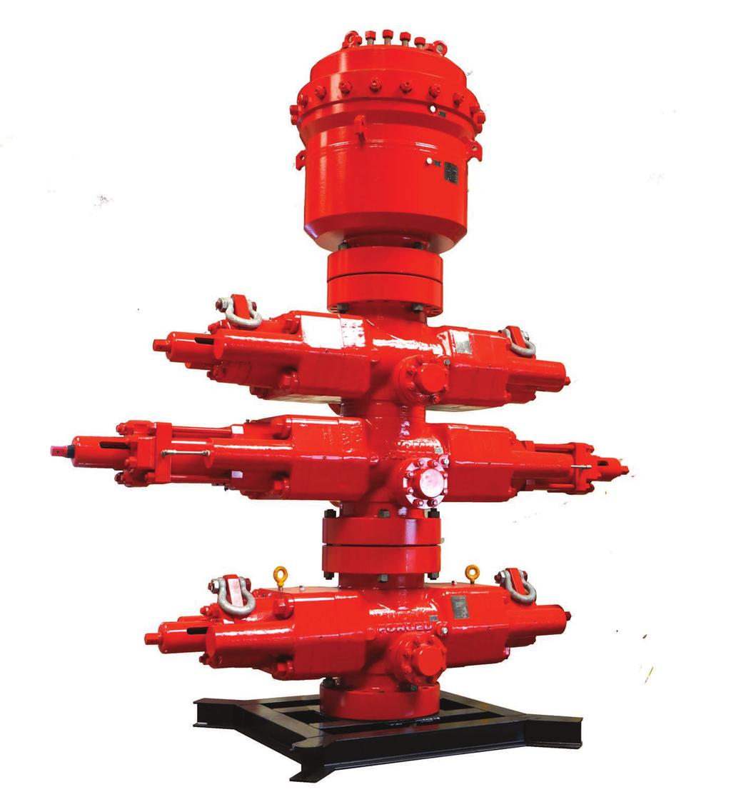
4 WOM s BOP Stack Typical WOM WGK Annular and WU Ram Type BOP Assembly WOM is certified to ISO Designed to NACE MR Materials Standards for resistance to sulfide stress cracking are standard. 4 WORLDWIDE OILFIELD MACHINE

5 WOM products are manufactured by the highest applicable standards. Computer controlled machine tools are used for dimensional accuracy, precision machining and consistent high quality. Each product is inspected, assembled and tested prior to shipment. This attention to detail ensures product quality and on time delivery. All buyouts like fittings, elastomers such as O rings, stem packing are supplied by WOM-Houston, headquarters. The assembly and testing of the valves is performed in a controlled area free from contamination. The assembly and testing conforms to written assembly and testing procedures, which are strictly enforced in order to maintain the high quality of our products. Material specifications, including heat treatment, mill tests, equipment tests are maintained in our manufacturing files which when requested can be supplied to the customer. Attention to detail ensures product quality and on-time delivery. 5

6 WU BOP Major Features The U BOP is the most widely used BOP type in the world today. Its simple, compact design makes it well suited for operations offshore and onshore. WOM s ram type WU BOP operating system is designed to provide a fast and reliable closure around pipe or casing in the well bore. The sealing is energized by the pressure and is maintained even with loss of closing pressure Major components are forged or cast for uniform strength, impact resistance and freedom from defects. 2. Ram packing is generous and self-feeding. It cannot be dislodged by fluid flow. 3. Operating pressure is moderate, due to large piston area. 4. Bonnets are opened and closed by hydraulic pressure. 5. Ram change is quick and easy. 6. All working parts and control fluid passages are enclosed. 7. Well bore pressure aids in holding rams closed. View of Major Components 8. Two seals and a vent hole prevent well pressure from bleeding into operating cylinder. 9. Rams can be locked in closed position by optional hydraulic ram locks. Release of locks is positive when opening of rams is desired. 10. All operating parts, as well as rams and seals, can be replaced on location, thus providing a completely reconditioned preventer. 11. We offer triple-seal protection from the well pressure. 6
7 WU BOP Specifications The capital letters in the following designations refer to the WU BOP dimensional views and dimensions tables on pages 8 and 9. A-1 Length: Bonnets closed, locking screws locked A-2 Length: Bonnets opened, locking screws unlocked A-3 Length: Bonnets closed with wedgelocks A-4 Length: Bonnets opened with wedgelocks B-1 Height: Flanged B-2 Height: Clump hubs C Width: No side outlets E-1 Centerline of side outlet to bottom flange face E-2 Centerline of side outlet to bottom hub face F-1 Top of upper ram to top flange face F-2 Top of upper ram to top hub face G Height of Ram H-1 Centerline of side outlet between rams to bottom hub face H-2 Centerline of side outlet between rams to bottom hub face J Top of lower ram to bottom of upper ram The following applications apply to typical WU type BOPs. Side outlets to 4-1/16 can be provided beneath each set of rams on either or both sides of WU BOPs. Side outlets can be studded, open-faced flange, or clamp hub. Flanges conform to API standards 6A and/or 16A. Hubs conform to API 16A or applicable standards. Type 6BX flanges are standard for 10,000 and 15,000 psi working pressures and for 5,000 psi for 13-5/8 and larger bore BOP s. Hydraulic control connections for operation of rams and bonnets are 1 NPT. There are (2) connections for each set of rams. Wedgelock connections are ½ NPT. The dimensions table (page 7 and 8) does not include spacers between rams for double ram models. WU BOPs with spacers to clear tool joints are available upon request. Large bore shearing bonnets are available for shearing high-strength pipe. All WOM WU BOPs are suitable for H2S service as standard. The WU BOP can be outfitted with blind rams, shearing/blind rams, pipe, casing, or tubing rams, or variable-bore rams. 7
8 WU BOP Dimensional Data (Single) C Top View of Single WU BOP A F B G E Side View of Single WU BOP Single Open-Faced Flange or Clamp Hub WU BOP Dimensions * * Size Pressure Rating (psi) Vertical Bore A 1 A 2 A 3 A 4 B 1 B 2 C E 1 E 2 F 1 F 2 G 7 1/16 3, / , /16 5, / , /16 10, / , /16 15, / , , , , , , , , , /8 3, / , /8 5, / , /8 10, / , /8 15, / , /4 10, / , /4 15, / , /4 3, / , /4 2, / , /4 3, / ,000 Approx. Weight (lbs) *Size 18-3/4 is currently under Research and Development 8
9 WU BOP Dimensional Data (Double) C Top View of Double WU BOP A F G B J G H E Side View of Double WU BOP Double Open-Faced Flange or Clamp Hub WU BOP Dimensions Size Pressure Rating (psi) Vertical Bore A-1 A-2 A-3 A-4 B-1 (Flanged) B-2 (Clamp) C E-1 E-2 F-1 F-2 G H-1 (Flanged) H-2 (Clamp) J (Between) Approx. Weight (lbs) 7-1/16 3, / , /16 5, / , /16 10, / , /16 15, / , , , , , , , , , /8 3, / , /8 5, / , /8 10, / ,400 * * 13-5/8 15, / , /4 10, / , /4 15, / , /4 3, / , /4 2, / , /4 3, / ,200 *Size 18-3/4 is currently under Research and Development 9
10 WU BOP Components WU BOP Parts 7A A 2A 6A 3A 5A 4A 10 1A WU BOP Large -Bore Shear Bonnet Assembly
11 WU BOP Parts Item Number WU BOP Parts Description 1 Body 2 Intermediate Flange 3 Bonnet 4 Ram Assembly (not shown) 5 Piston, Operating 6 Cylinder, Operating 7 Housing, Locking Screw 8 Locking Screw 9 Piston, Ram Change/Open 10 Piston, Ram Change/Close 11 Cylinder, Ram Change 12 Bolt, Bonnet 13 Stud, Locking Screw Housing 14 Nut, Locking Screw Housing 15 Check Valve, Plastic Packing 16 Screw, Plastic Packing 17 Pipe Plug, Plastic Packing 18 Ring, Plastic Packing 19 Ring, Plastic Energizing 20 Seal Ring, Connecting Rod 21 Ring Back-Up 22 Seal, Bonnet 23 Pin, Ram Guide 24 O-Ring, Operating Cylinder 25 O-ring, Operating Piston Rod to Int. Flg 26 Lip Seal, Operating Piston 27 Seal Ring, Tail Rod 28 O-Ring Wiping 29 O-Ring, Ram Change Piston to Body 30 O-Ring, Ram Change Piston Rod to Int. Flg. 31 O-Ring, Ram Change Cylinder to Int. Flg 32 O-Ring, Ram Change Cylinder to Bonnet 33 O-Ring, Ram Change Piston 34 O-Ring, Bonnet Bolt Retainer 35 Cap Screw, Int. Flange to Bonnet 36 Gland Bleeder 37 Plug Bleeder *Lifting Eye (not shown) Plastic Packing 40 Washer 41 Ring, Retainer 42 Wear Ring, Operating Piston 1A 2A 3A 4A 5A 6A 7A 8A Large Bore Shear Bonnet Parts Intermediate Flange Bonnet/Shear Operating Piston/LB O-Ring, Int. Flg to Bonnet Lip Lip Seal, Operating Piston/LB Wear Ring, Operating Piston/LB Bonnet Bolt Shear Lockscrew Shear Large bore shear bonnets provide a larger operating piston to increase shearing force. Part Numbers for WU BOP *38 - Must be ordered seperately All dimensions are in inches unless otherwise noted. 11
12 Rams for WU BOPs WU BOP Pipe Rams WU BOP pipe rams are available to fit a wide variety of tubing, drill pipe, drill collar, and casing sizes. All rams are suitable for H2S service per NACE specifications. WU BOP ram packers are selffeeding with a large reserve of elastomer to ensure a long-lasting seal under all conditions. Ram packers lock into place and cannot be dislodged by well flow. Top Seal Ram Packer Pipe Rams WU BOP Variable Bore Rams WU BOP variable bore rams can be used to seal on a range of pipe. WOM s WU BOP variable bore ram packers contain steel reinforcing inserts similar to those in the annular BOP packer. The inserts rotate inward when the rams are closed so the steel provides support for the rubber which seals against the pipe. WU BOP Shearing Blind Rams Shearing blind rams (SBR) can be used as blindrams during normal operations, they are specifically designed to shear the pipe in the hole then bend the lower section of the sheared pipe to allow the rams to close and seal. One set of WU BOP variable bore rams can be used to seal on a range of pipe. WOM s WU BOP variable bore ram packers contain steel reinforcing inserts similar to those in the annular BOP packer. The inserts rotate inward when the rams are closed so the steel provides support for the rubber which seals against the pipe. The large area of the blade face seal reduces pressure on the rubber and increases service life. WOM SBRs can cut pipe numerous times without damage to the cutting edge. Ram Top Seal Lower Ram Packer Variable Bore Rams Top Seal Side Packer Side Packer Blade Packer Shearing Blind Rams 12

13 Hydraulic Control System View of Hydraulic Control System Ram Close Circuit in Red Ram Open Circuit in Green Hydraulic Circuits The ram close hydraulic circuit is shown in red on the above caption. The ram closing pressure also serves to open the bonnets for ram change. When the bonnet bolts are unscrewed and closing pressure is applied, pressure pushes the ram inward and at the same time moves the bonnet away from the preventer body. Even though the ram moves inward, the bonnet stroke is sufficient to bring the ram into the clear for handling. An eyebolt is furnished on each end of the Preventer body which can be screwed into the top of each ram for lifting. The ram open hydraulic circuit is shown in green on the above caption. Ram opening pressure also serves to close the bonnets. Hydraulic control pressure draws the bonnets tightly against the preventer body; bolts serve only to hold bonnets closed. An important feature of the Type WU hydraulic system is that the rams are pulled back close to the bonnets before the bonnets begin moving toward the Preventer body. Because of this, rams never interfere with pipe in the hole or otherwise obstruct the vertical bore. Rams may be changed, in an emergency, when the well is blowing, thereby increasing the security provided by the preventers. Pressure Required The rated continuous working pressure for the Type WU BOP operating system is 1,500 psi. Pressures of 300 to 500 psi normally provide satisfactory operation. Pressures in excess of 1,500 psi may be required in 10,000 and 15,000 psi preventers to close the rams against high well pressures. In emergencies, pressures up to 4,500 psi can be applied to the hydraulic controls. For optimum seal life, the applied hydraulic pressure should be limited to 1,500 psi, especially when it is customary to hold ram open pressure on preventers continuously. When a 3,000 psi accumulator is used to store maximum energy for preventer operation, a pressure regulator should be used to control pressure applied to the preventer. Operating Fluids Light hydraulic oil is the recommended operating fluid for Type WU preventers. Any type is satisfactory except fuel oil, which causes rubber seals to swell and deteriorate. The use of water as an operating medium is satisfactory provided soluble oil is added to prevent corrosion and antifreeze is added when necessary. Should an emergency require the use of drilling mud pressure to operate a Preventer, the Preventer should be torn down, thoroughly cleaned and all seals carefully checked for excessive wear as soon as practical thereafter. 13

14 Super Power (SP) Tandem Booster* WOM s new Super Power (SP)-Tandem Boosters* are designed to enhance the shearing force of Ram-type BOPs. WOM s SP Tandem Boosters offer more advantages and benefits over those of traditional shear boosters. May be utilized on any size of ram-type BOP such as but not limited to 7-1/16, 11, 13-5/8, 18 ¾ and 21 ¼. Offers ability to shear larger and heavier sizes of drill pipe required for deep drilling, where extra heavy wall-thickness is required for hydrocarbon producing wells or extreme sour environments. SP-Tandem Boosters with large bore bonnets have a rigid power of approximately one million pound force, capable of shearing drill pipe at any extreme well condition and harsh environment. SP-Boosters provide twice the shearing force than traditional tandem boosters. SP-Tandem Boosters use of internal hydraulic flow path for hydraulic operations, eliminates external piping and exposure to damage during handling, storage, and shipping. Quick and easy field replacement of standard seals. The SP-Tandem Booster uses the same seals as the large bore piston and shaft seals. Rigid and robust design. Each part is engineered in-house to meet and/or exceed national petroleum industry code and standards. Requires only three main components: Housing, Piston and End Plate; making assembly and disassembly quicker with low maintenance. Eliminates the need for spacers, connectors, and other parts used in traditional tandem boosters. 14


15 Weighs less than traditional boosters. Existing WU BOPs and other OEM BOPs may be retrofitted with SP-Tandem boosters to provide extra shearing force. External hydraulic lines may be required for retrofit applications. May be utilized in smaller size ram-type BOPs, offering a reduction in size, weight and overall cost. WOM has successfully completed shear tests on 13 5/8 10,000-psi blowout preventer utilizing SP-Tandem Shear Booster for the following drill pipes, witnessed by WOM s certified quality assurance personnel as per API-16A guidelines. Drill Pipe OD 5, Grade S-135, PPF 25.6, closing pressure 2300-psi Drill Pipe OD 5 ½, Grade S-135, PPF 24.7, closing pressure 2200-psi Drill Pipe OD 6 5/8, Grade S-135, PPF 25.2, closing pressure 1500-psi Drill Pipe OD 6 5/8, Grade S-135, PPF 27.6, closing pressure 2,400-psi Above test criteria and governing rules meet the requirements of hydraulic closing pressure for drill pipe shear as per API-53 which is 90% below the rated hydraulic maximum pressure. (Test charts and test data is available on request) *Patent Pending 15
16 WU BOP Care & Maintenance Daily or Trip Care: All blowout Preventers should be operated daily. Many owners require that they be operated at the beginning of each tour. Blind rams should be operated every time pipe is out of the hole. Pipe rams should not be closed except when pipe is in the preventer, to avoid extruding the packer. If operation of the rams requires more than 500 psi control pressure when there is not pressure in the well bore, the cause should be determined and remedial measures taken. Care Between Wells: Whenever a preventer is removed from a drilling hookup, it should be carefully cleaned, and the rams should be removed, cleaned, inspected, and lubricated. Also, the ram bore should be cleaned, inspected and lubricated. Any burrs or galled spots should be smoothed. Rams may be stored in the preventer or separately. The operating system should be thoroughly flushed to remove sediment or foreign material. Type WU Preventers should be transported with rams closed and locking screws run in to avoid accidental bending of locking screws. Periodic Overhaul: Annually, or more often depending on the type of service, a preventer should be completely disassembled and all parts cleaned, inspected and reconditioned or replaced. All rubber seals should be replaced except ram packings which should be replaced according to condition. Any metal parts which show damage, such as scored pistons or cylinders, should be replaced or repaired. Preventer parts in some cases can be repaired; however, this should be done only at WOM repair shops or under supervision of WOM personnel. After the preventer is rebuilt, the body should be tested to maximum rated working pressure and the operating system to 5,000 psi. The Type WU Blowout Preventer has been designed especially for ease of field servicing and reconditioning. Ram change pistons and cylinders, and operating pistons and cylinders can be quickly replaced on location, providing a completely rebuilt bonnet assembly. Lubricants: Ram Lubricant: Any water resistant grease or heavy oil can be used as a ram and ram bore lubricant. Thread Lubricant: Metallic Zinc Base Grease should be used. Testing: At regular intervals, weekly if possible, the complete drilling hookup and choke manifold should be tested for pressure holding ability and correct operation. The blowout preventer operating unit and all control piping should also be pressure tested and inspected. Pipe rams should not be closed except when pipe is in the preventer, to avoid extruding the packing. Storage: When a preventer is put in storage, the rams should be removed and the preventer thoroughly cleaned, all moving parts greased, and all machined surfaces oiled and greased, particularly the ram bores and the flange ring grooves. Preferably, the preventer should be provided with flange protectors. Preventers in storage should have the operating system full of lightweight oil. Packed rams should not be stored out of doors. Spare Parts: It is recommended that spare pipe rams plus replacement packers and top seals for all sizes of rams being used be kept at the rig. There may be other spare parts that are recommended to support a year of operation, which depend on environmental conditions where the BOP is installed. Please contact WOM for a specific list of recommended spares. 16

17 Cold Weather Operation The operation of the Type WU Blowout preventer in sub-zero temperatures requires special precautions not normally necessary in the more temperate climates such as that of the Gulf Coast area. Some of these precautions are: 1. The preventer should be kept as warm as possible as the rams are susceptible to freezing in place since water-based drilling fluids freeze quickly and solidly when they come to rest at such temperatures. 2. Lubricants should be selected on their low temperature properties since some lubricants congeal at sub-zero temperatures and prevent the operations which they were intended to facilitate. 3. Avoid impact loads on rubber parts as they become very brittle and may shatter. 4. Use metallic hose in lieu of rubber hose due to rubber embrittlement. 5. Light hydraulic oil should be used in the Type WU hydraulic system since some mediumweight oils become semi-solid at temperatures in the neighborhood of fifty degrees below zero. 6. Keep the equipment clean and free of water-based drilling fluids where at all possible. 7. Operate the equipment as frequently as possible. 8. Water is satisfactory operating fluid provided a soluble oil is used for corrosion protection and sufficient antifreeze is added to prevent freezing. 17
18 WGK Annular Type BOP Screw and Latch Type WOM s Type WGK BOP was designed especially for surface installations and is also used on offshore platforms. The WGK is a universal annular blowout preventer with a long record of proven, quality performance. Standard operation requires both opening and closing pressure. Seal-off is affected by hydraulic pressure applied to the closing chamber which raises the piston, forcing the packing unit into a sealing engagement. Any normal closing unit having a separate pressure regulator valve for the annular BOP and sufficient accumulator volume can be used to operate the WGK. The WGK is designed to be well pressure assisted in maintaining packing unit seal off once initial seal off has been effected. As well pressure further increases, closure is maintained by well pressure alone. WOM WGK BOP (Screw Type) Pressure Energized Seals are used for dynamically sealing piston chambers to provide safe operation, long seal life, and less maintenance. Piston Sealing Surfaces Protected by Operating Fluid lowers friction and protects against galling and wear to increase seal life and reduce maintenance. Operating Chambers are Tested to Full BOP Working Pressure to ensure strength, reliability, and the ability to over-pressurize the chambers in emergencies. WOM WGK BOP (Latch Type) 18 WORLDWIDE OILFIELD MACHINE
19 WGK Major Components Lid Wear Plate Packing Unit Opening Chamber Piston Closing Chamber Cage Body Major Components 19

20 WGK Hydraulic Control System The surface hookup of the WGK connects the hydraulic control lines to the opening and closing chambers of the BOP. Pressure applied to the closing chamber raises the piston and affects the initial seal between the packing unit and drill pipe. Well pressure or test pressure also acts on the piston below the sealed off packing unit and further increases the closing force acting on the packing unit. As the well pressure or test pressure exceeds the required level the preventer is maintained closed by well pressure alone. As well pressure increases, the closing force on the packing unit also increases. Closing pressure should be proportionally reduced as well pressure is increased in order to maintain optimum closing force on the packing unit and prolong packing unit life. During normal drilling operations, it is recommended that the pressure regulator valve for the WGK be set at the initial closing pressure for the size pipe being used. This pressure will ensure that initial seal off is achieved should a kick be encountered. During BOP testing operations, once initial seal off is achieved, closing pressure should be proportionally reduced as well pressure is increased. 20


21 WGK Annular Type BOP Only Two Moving Parts (piston and packing unit) on the Annular BOP mean few areas are subject to wear. The BOP is safer and more efficient, requiring less maintenance and less downtime. Long Piston with a length to diameter ratio approaching one eliminates tendencies to cock and bind during operations with off-center pipe or unevenly distributed accumulations of sand, cuttings, or other elements. This design enhances the ability of the packing unit to reopen to full bore position. Conical Bowl Design of the Piston provides a simple and efficient method of closing the packing unit. With the piston serving as a sealing surface against the rubber packing unit, there is no metal-to-metal wear on the sealing surface and thus longer life results. Field Replaceable Wear Plate in the BOP Lid serves as an upper non-sealing wear surface for the movement of the packing unit, making field repair fast and economical. Maximum Packing Unit Life is possible with the provision for measuring piston stroke. This measurement indicates remaining packing unit life without disassembly and ensures the longest and safest use of the packing unit. A Three Choices of Packing Unit Rubber Compounds permit more flexible applications. Screwed Lid Design of the WGK BOP Screw type is a Simple, Efficient, and Strong method of connecting the lid to the body for safe operation with no loose parts being lost down the hole or overboard. Pressure Energized Seals are used for dynamically sealing piston chambers to provide safe operation, long seal life, and less maintenance. Piston Sealing Surfaces Protected by Operating Fluid lowers friction and protects against galling and wear to increase seal life and reduce maintenance. Operating Chambers are Tested to Full BOP Working Pressure to ensure strength, reliability, and the ability to over-pressurize the chambers in emergencies. B C WOM s WGK Annular BOP Screw Type A- Height B- Body Diameter C- Clearence Diameter See Engineering and Dimensional Data on page 22 NACE MR Materials Standards for resistance to sulfide stress cracking are standard. 21
22 WGK Engineering & Dimensional Data (Screw Type) Head Type Operating Chamber Volume (Gal) Closing Opening 7-1/16-3M 7-1/16-5M 7-1/16-10M 7-1/16-15M 11-3M Screw Type Screw Type Screw Type Screw Type Screw Type Full Piston Stroke 4-1/8 4-1/8 5-1/2 5-1/2 6-1/8 Body Diameter (B) Clearance Diameter (C) Height (A) Flanged Bottom Studded Bottom Hub Bottom Weight (lbs) Flanged Bottom Studded Bottom Hub Bottom Standard Ring Groove Flanged Bottom Studded Bottom Hub Bottom RX45 RX45 RX RX467 RX46 RX ,200 11,900 BX156 BX ,250 BX156 BX ,500 5,140 5,350 RX53 RX53 RX53 Head Type Operating Chamber Volume (Gal) Closing Opening 11-5M 11-10M 13-5/8-3M 13-5/8-5M 13-5/8-10M Screw Type Screw Type Screw Type Screw Type Screw Type Full Piston Stroke 7-1/ /8 8-1/2 10-1/2 Body Diameter (B) Clearance Diameter (C) Height (A) Flanged Bottom Studded Bottom Hub Bottom Weight (lbs) Flanged Bottom Studded Bottom Hub Bottom Standard Ring Groove Flanged Bottom Studded Bottom Hub Bottom RX54 RX54 RX ,140 25,460 26,000 BX158 BX158 BX ,784 8,522 8,650 RX57 RX57 RX ,800 13,100 BX160 BX160 BX ,525 32,850 32,785 BX159 BX159 BX159 22
23 WGK Engineering Dimensional Data (Latch Type) 11" 10K 13 5/8" 5K 13 5/8" 10K 21 1/4" 2K Bore 11 " 13 5/8" 13 5/8" 21 1/4" Working Pressure 10,000 psi 5,000 psi 10,000 psi 2,000 psi Shell Test Pressure (Factory Test Only) 15,000 psi 7,500 psi 15,000 psi 3,000 psi Closing Chamber Test Pressure (Factory Test Only) 2,250 psi 2,250 psi 2,250 psi 2,250 psi Opening Chamber Test Pressure (Factory Test Only) 2,250 psi 2,250 psi 2,250 psi 2,250 psi Volume Closing Chamber 25.1 gallons gallons gallons 31.1 gallons Volume Opening Chamber 18.9 gallons gallons gallons 18.9 gallons Piston Stroke 8" 8 1/2" 10 1/2" 11 1/4" Port Size 1 NPT 1 NPT 1 NPT 1 NPT Weight (Varies with end connec ons) 22,100 lbs 14,800 lbs 35,865 lbs 15,750 lbs A A- Height B- Body Diameter C- Clearence Diameter B WORLDWIDE OILFIELD MACHINE C 23

24 WGK Packing Unit The heart of the WGK blowout preventer is the packing unit. The unit is manufactured from high quality rubber, reinforced with flanged steel segments. Each unit has a large volume of tough, feedable rubber to meet any requirement. The molded in steel segments have flanges at the top and bottom. These segments anchor the packing unit within the blowout preventer and control rubber extrusion and flow when sealing off well pressures. Since the rubber is confined and kept under compression, it is resistant to tears, cuts, and abrasion. Packing Unit Packing Unit Selection All annular blowout preventer packing units are subjected to wear during closure and stripping. The design of the WGK blowout preventer causes closure wear to occur on the outside of the packing unit while stripping wear occurs on the inside. Thus, the stripping life of the packing unit is little affected by wear from routine closures. Natural Rubber is compounded for drilling with water-base drilling fluids. Natural rubber can be used at operating temperatures between -30 o F to 225 o F. Nitrile Rubber (a synthetic compound) is for use with oil-base or oil-additive drilling fluids. It provides the best service with oil-base muds, when operated at temperatures between 20 o F to 190 o F. Neoprene Rubber is for low-temperature operating service and oil-base drilling fluids. It can be used at operating temperatures between -30 o F to +170 o F. Neoprene rubber provides better service with oil-base drilling fluids than Natural rubber. It has better cold temperature elasticity than Nitrile rubber; but it is detrimentally affected by extended high temperature applications. Seals are manufactured from a special Nitrile rubber material which provides long, trouble free service in sealing against oil, gas, or water. Expected H2S Service does not affect selection of packing unit material. H 2 S Service will reduce the service life of rubber products, but the best overall service life is obtained by matching the packing unit material with the requirements of the specific drilling fluid. Performance of elastomeric materials can vary significantly, depending on the nature and extent of exposure to hydrogen sulfide. The operator should monitor pressure sealing integrity frequently to assure no performance degradation has occurred. Storage conditions such as light, heat, or adverse conditions, are significant factors in the storage life of packing units. 24
25 WGK BOP Care & Maintenance (Screw & Latch Type) Prior to placing the GK blowout preventer into service, the following visual inspections should be performed: 1. Inspect upper and lower connections for pitting, wear, and damage especially in ring grooves and stud bolt holes. Worn or damaged ring grooves must be welded, machined, and stress relieved. Worn or damaged stud bolt holes can be drilled and tapped to the next larger size and fitted with step-studs. 2. Check the body for wear and damage, especially in the internal cylinder walls for pits and vertical scores. Minor pits and scores can be removed in the field with emery cloth. Repaired surface should be coated with silicon grease or castor oil. Severe pits and scores may require machining and/or welding which should be performed in a WOM approved machine shop. Cracks must be corrected. 3. Inspect the vertical bore for wear and damage from drill string and drill tools, especially in the area of the ring grooves. If wear is excessive, the area must be repaired. 4. Check for piston damage and wear, especially the inner and outer walls for pits and vertical scores and the tapered bowl for pits and gouges. Minor pits and scores on the walls can be removed in the field with emery cloth. Repaired surface should be coated with silicon grease or castor oil. Severe pits and scores may require machining and/or welding which should be performed by a WOM approved machine shop. Pits and gouges in the tapered bowl should be filled with a permanent type adhesive, such as epoxy. Sharp or rolled edges should be removed with emery cloth or a grinder. Repair will be satisfactory when a relatively smooth surface is achieved. 5. Check the wear plate in the inner bottom face of the lid for any abrasion. In addition to the aging process of time and use, wear of this metal surface is produced by the combination of vertical (upward thrust) and lateral forces. These forces are generated each time the packing unit is closed. Severe wear is exhibited in the form of grooves or channels shaped by the steel segments of the packing unit. The inner bottom face of the lid serves as a wall to prevent upward movement of the packing unit. Friction between these metal surfaces is controlled at a level which does not impair lateral movement of the packing unit. Repair of this surface is accomplished by replacing the wear plate. 6. Inspect the packing unit for wear, cracking, hardness, and correct elastomer composition. 7. Check seal ring for nicks, cuts, fraying of lips, and abrasion. Worn or damaged seal rings should be replaced. 25
26 29 1/2 500 PSI MSP Diverter (Latch Type) The MSP Diverter was developed as a compact, lightweight unit for medium pressure drilling service, remedial work and well servicing. It can be used on surface and subsea installations. Standard operation requires both opening and closing pressure. Seal off is affected by hydraulic pressure applied to the closing chamber which raises the piston, forcing the packing unit into a sealing engagement. Any normal closing unit having a seperate regulator valve for the annular BOP and sufficient accumulator volume can be used to operate the MSP. 29 1/2 500 PSI MSP Diverter Parts MSP Diverter (Latched) Item Description Body Lid Piston Cage Locking Plate, Long Locking Plate, Short Wear Plate Packing Element Pipe Plug, Hex HD Pipe Plug, Socket HD. Hex Hd. Cap Screw Hex Hd. Cap Screw Stud Nut O-ring: Lid O-ring: Upper, Piston Non-extrusion ring: Outer, Piston U-seal: Double, Outer, Piston U-seal: Inner, Piston O-ring: Cage Anchor Shackle 26 WORLDWIDE OILFIELD MACHINE
27 WORLDWIDE OILFIELD MACHINE


28 WORLDWIDE OILFIELD MACHINE Est. 1980
BLOWOUT PREVENTERS. Invention Unique Design & Extraordinary Craftsmanship
 BLOWOUT PREVENTERS TM Invention Unique Design & Extraordinary Craftsmanship 1 Table of Contents WOM s BOP Stack 4 WU BOP Major Features 6 WU BOP Specifications 7 WU BOP Dimensional Data (Single) 8 WU
Cameron International Corporation
 Cameron International Corporation 2 Cameron International Corporation About this Catalog The purpose of this catalog is to serve as a quick reference for our customers. However, many of Cameron s products
2002 Replacement Parts Catalog
 2002 Replacement Parts Catalog Please visit our website at http://www.camerondiv.com TRANSACT with CAMERON COMMERCE The Cameron Commerce function of TRANSACT offers an online, 24/7 purchasing tool for
HYDRIL COMPANY LP / P.O. BOX / HOUSTON TEXAS PHONE: (281) / FAX: (281) / WEB:
 / FAX: (281) / WEB:") Please contact Hydril Pressure Control Equipment for any assistance or questions concerning the information in this manual. All information in this manual is the exclusive property of Hydril Company LP.
Please contact Hydril Pressure Control Equipment for any assistance or questions concerning the information in this manual. All information in this manual is the exclusive property of Hydril Company LP.
Fast, Effective Blowout Protection
 Dual or Single Ram Hydraulic BOPs Fast, Effective Blowout Protection MODEL DRH - DUAL RAM HYDRAULIC BOP Guide Rib Pipe Centering Guide Ram Rubber Pipe Ram Block Door Cylinder Locking Shaft Lip-Type Piston
D and DL Annular Blowout Preventers
 D and DL Annular Blowout Preventers In the unique design of the Cameron DL Annular BOP, closing pressure forces the operating piston and pusher plate upward to displace the solid elastomer donut and force
Top View Single or Double. Side View - Single. Table 1
 -1 Length, bonnets closed locking screws in -2 Length, bonnets open, locking screws out -3 Length, bonnets closed, with wedgelocks -4 Length, bonnets open with wedgelocks B-1 Height, PI flange single B-2
TL BOP. TL Custom Features:
 TL BOP The Cameron TL BOP product line is the result of an evolution of Cameron s successful U, UII and T BOPs combined with custom features based on each customer s specific requirements. All TL BOPs
T BOP. prep. TC Cooper Cameron, Cameron Division
 T BOP The Cameron T blowout preventer offers a unique combination of benefits including safety, economy, reliability, extended service life, reduced height and fast and easy service. Side ram removal on
U Blowout Preventer 13-5/8" 10,000 psi WP
 Operation and Maintenance Manual U Blowout Preventer 13-5/8" 10,000 psi WP TC1075 All the information contained in this manual is the exclusive property of Cooper Cameron Corporation, Cameron Division.
C BOP. TC Cooper Cameron, Cameron Division
 C BOP The Cameron C BOP was designed as an emergency safety head for snubbing coiled tubing workover applications. The main function of the C BOP is to shear whatever is in the hole - from braided cable
Drilling & Down-hole Completion Tools
 HYDRAULIC SET PRODUCTION PACKER MODEL: WC-HP-1 & WC-HPL-1[Large Bore] PRODUCT No.: WC-20101 & WC-20112 HP-1 is an industry standard, fully hydrostatic, hydraulic set and shear release single string retrievable
SUNNDA CORPORATION. Pressure Control Equipment. Boost Your Bottom Line! Sunnda Corporation
 SUNNDA CORPORATION Boost Your Bottom Line! Pressure Control Equipment Sunnda Corporation 4543 Brittmoore Road, Houston, TX 77041 USA Phone: +1-713-849-5678 Fax: +1-713-849-5687 E-mail: sales@sunnda.com
MAGNUM GATE VALVES. Invention, Unique Design & Extraordinary Craftsmanship. WORLDWIDE OILFIELD MACHINE Est. 1980
 TM MAGNUM GATE VALVES www.womusa.com Invention, Unique Design & Extraordinary Craftsmanship WORLDWIDE OILFIELD MACHINE Est. 980 Table of Contents Patented Dual-Seal Technology Magnum Gate Valve 2 Magnum
Bray/ VAAS Slurry Series Knife Gate Valve 760/762/765/766/767/768 Series Operation and Maintenance Manual
 Bray/ VAAS Knife Gate Valve 760/762/765/766/767/768 Series Table of Contents Definition of Terms 1 Safety Instructions 1 Introduction 2 Unpacking 2 Storage 2 Installation 3 Commissioning 3 Cylinder-Operated
Boss Oilwell offers a complete line of API 16A BOPs, API 16C drilling manifold The ultimate solution for onshore & offshore BOPs
 Boss Oilwell offers a complete line of API 16A BOPs, API 16C drilling manifold. -------The ultimate solution for onshore & offshore BOPs------- Boss Oilwell Products & Manufacturing INC(BOPM) specializes
GROVE B4, B5 and B7 Side-entry Ball Valves
 GROVE B4, B5 and B7 Side-entry Ball Valves Table of Contents GROVE B4, B5 and B7 SIDE-ENTRY BALL VALVES Features and Benefits Applications...1 GROVE B4 Design Features...2 Materials Specifications...4
PBV s Engineering Excellence At Work
 PBV s Engineering Excellence At Work The PBV Series 5700/6700 Three-Piece, Side-Entry, Trunnion Ball Valve 2"- 56" ANSI Class 150/300,600,900,1500 & 2500 In Full And Standard Port PBV trunnion ball valves
BULLETIN August 2009 PERMASEAL PLUG VALVE. ISO 9001:2008 Certified QMS. SMG Valves A Unit of Southern Manufacturing Group, Inc.
 BULLETIN 13.01-01 August 2009 PERMASEAL ISO 9001:2008 Certified QMS SMG Valves A Unit of Southern Manufacturing Group, Inc. Design and Construction Permaseal Plug Valves are designed for on-off and diverting
COYOTE ENTERPRISES, INC. 9/10 BLAST WHEEL MAINTENANCE & ASSEMBLY MANUAL
 COYOTE ENTERPRISES, INC. 9/10 BLAST WHEEL MAINTENANCE & ASSEMBLY MANUAL Parts & Machinery for the Abrasive Blast Industry 27301 East 121st Street Coweta, Oklahoma 74429 (918) 486-8411 Fax (918) 486-8412
4 - Way Control 4 - Way Control 4 - Way Control with lock
 INSTALLATION / OPERATION / MAINTENANCE 1. DESCRIPTION MODEL 0-02 (Full Internal Port) Powertrol Valve This manual contains information for installation, operation and maintenance of the Cla-Val Co. 0-02
McCannalok HIGH PERFORMANCE BUTTERFLY VALVE OPERATION AND MAINTENANCE MANUAL. The High Performance Company
 McCannalok HIGH PERFORMANCE BUTTERFLY VALVE OPERATION AND MAINTENANCE MANUAL The High Performance Company Table of Contents Safety Information - Definition of Terms... 1 Introduction... 1 Installation...
Spring Brake Application
 Technical Tip Maxibrake I Series Spring Brakes Disassembly, Inspections and Reconditioning Instructions Maxibrake I Series spring brake products are mechanical devices and are subject to wear after extended
E N G I N E E R E D V A L V E S. B4, B5 & B7 Side Entry Ball Valves GROVE
 B4, B5 & B7 Side Entry Ball Valves TABLE OF CONTENTS B4 B5 B7 SIDE ENTRY BALL VALVE FEATURES AND BENEFITS General Information 1 B4 Design Features 2 & 3 Valve Assembly and Cross Section 4 Dimensions and
1/2" AIR DRIVEN DIAPHRAGM PUMP
 1/2" DRIVEN DIAPHRAGM PUMP OPERATION AND SERVICE GUIDE O-1225D NOV. 2008 Page 1 of 6 Refer to Bulletin P-605, Parts List P-9151 DRIVEN, DOUBLE DIAPHRAGM PUMP MANUAL Congratulations on purchasing one of
NOTICE: Section 1.22 Connecting Rod
 Page 1 of 11 Section 1.22 Connecting Rod Two types of connecting rod are used in Series 60 engines. The open end or saddle type connecting rod is used with cast iron pistons which have bolt-on, style piston
Oilman Group API 6A PRODUCTS OILMAN GROUP LTD. Shanghai Houston
 API 6A PRODUCTS OILMAN GROUP LTD 1 BOMCO Guanghan Drilling & Production Equipment Factory is a subsidiary of CNPC and provides the best API 6A & 16A products to esteemed customers all over the world. 2
1100 Series Multi-Stage Vertical Turbine Pumps
 1100 Series Multi-Stage Vertical Turbine Pumps Capacities to 40,000 GPM Heads to 1,500 Feet Temperatures to 200 F Water Lubricated Open Lineshaft Vertical Hollow Shaft Motor The vertical hollow shaft motor
J-1 RELAY VALVE, Part No J-1 RELAY VALVE PORTION, Part No
 J-1 RELAY VALVE, Part No. 557290 J-1 RELAY VALVE PORTION, Part No. 556441 (Single Diaphragm Type) NOVEMBER, 1984 Supersedes issue dated November, 1981 NOTE: The following description and operation is based
GT-200 GATE VALVES PN16, Screwed end
 Document No. : MD-QO-04-281 Date : 2009/07 /17 Version : 1.0 GT-200 GATE VALVES PN16, Screwed end USER MANUAL Modentic Industrial Corporation 14F-1,No.57Taya Rd.,Taichung,Taiwan,R.O.C. Email:modentic@ms9.hinet.net
Installation Instructions
 Preparing your vehicle to install your brake system upgrade 1. Rack the vehicle. 2. If you don t have a rack, then you must take extra safety precautions. 3. Choose a firmly packed and level ground to
DEMCO Model DM Gate Valves
 Page of 24 Installation, Operation, Maintenance and Repair Manual DEMCO Model DM Gate Valves Classes : 400 000 600 2000 900 3000 500 5000 Page 2 of 24 Published May 2002 Cooper Cameron Corporation, Cooper
SECTION 4 - FUEL/LUBRICATION/COOLING
 For Arctic Cat Discount Parts Call 606-678-9623 or 606-561-4983 SECTION 4 - FUEL/LUBRICATION/COOLING 4 TABLE OF CONTENTS Carburetor Specifications... 4-2 Carburetor Schematic... 4-2 Carburetor... 4-3 Cleaning
 DRUM BRAKE RIMS Periodic inspection of drum brake rims is necessary to determine indications of uneven or excessive wear. In general, brake rim failures other that regular wear are caused by brake linings
OPERATION & MAINTENANCE MANUAL API 6A SLAB GATE VALVE AAS-013 REV C
 OPERATION & MAINTENANCE MANUAL API 6A SLAB GATE VALVE AAS-013 REV C TABLE OF CONTENTS I. Introduction............................................. 3 II. Installation and Operating Instructions..............................
SWING CHECK VALVES SERIES 52-SC SERIES 600
 SWING CHECK VALVES SERIES 52-SC SERIES 600 FEATURES/BENEFITS/SPECIFICATIONS AMERICAN Flow Control Series 52-SC Swing Check Valves incorporate design features to help increase service life for water and
TC20 Chain Driven Power Take-Off Overhaul Instructions
 TC20 Chain Driven Power Take-Off Overhaul Instructions Table of Contents Section Page Introduction 4 Ordering Repair Parts 4 General Information 5 Special Tools 6 Disassembly See Page 2 Reassembly See
Choke & Kill Manifolds
 Manifold Systems Drilling, Production,Testing TM Invention Unique Design & Extraordinary Craftsmanship Choke & Kill Manifolds WOM specializes in the manufacture of manifolds for a complete range of onshore
Installation Instructions
 Installation Instructions BW Seals RIS Seal Rubber in shear slurry seal Experience In Motion 1 Equipment Check 1.1 Follow plant safety regulations prior to equipment disassembly: lock out motor and valves.
JUL 17 Rev M
 Hand Crimping Tool and Cable Preparation Kit; PN 59981-1 Instruction Sheet 408-6788 24 JUL 17 Rev M PROPER USE GUIDELINES Cumulative Trauma Disorders can result from the prolonged use of manually powered
Drop-In Inside Blowout Preventer Valve
 Drop-In Inside Blowout Preventer Valve Disassembly and Assembly Procedures Global Manufacturing, Inc. Lafayette, Louisiana USA 70508 Ph (337) 237-1727 Fax (337) 232-9353 Disassembly and Assembly Procedures
Apollo Standard Port, Full Port & One Piece Flanged Ball Valves Installation, Operation, & Maintenance Guide
 I854000.F M16005 Apollo Standard Port, Full Port & One Piece Flanged Ball Valves Introduction This manual presents guidelines for the Installation, Operation and Maintenance of manual and automated Apollo
MUELLER ECCENTRIC PLUG VALVE
 MUELLER INSTALLATION, OPERATING and MAINTENANCE INSTRUCTIONS 1 MUELLER System Design The life of the valve is dependent on its application, frequency of use and freedom from misuse. The properties of the
Fire Protection. FP-XA End Suction
 Fire Protection FP-XA End Suction PRODUCT BULLETIN MODEL FP-XA END SUCTION CPS Model FP-XA End Suction pumps are used in a variety of fire fighting applications. These rugged and efficient centrifugal
JFETIGER RUNNING MANUAL. Downloaded From JFETC.COM Thu, 20 Sep :15: JFETIGER. * valid at time of download * JANUARY 2015
 JFETIGER-TP-M-001 (REV.3) JFETIGER RUNNING MANUAL JFETIGER JANUARY 2015 JFE STEEL CORPORATION CONTENTS JFETIGER... 1 PREFACE...1 1 PREPARATIONS BEFORE RUNNING...1 1.1 Handle Pipes Carefully...1 1.2 Racking
MODCO TM FIGURE 500 CLOSURE
 CLOSURE SPECIALISTS SINCE 1981 MODCO TM FIGURE 500 CLOSURE INSTALLATION INSTRUCTIONS (!) THE INFORMATION PROVIDED IN THIS DOCUMENT IS VERY IMPORTANT (!) & (!) needs to be shared with everyone involved
Installation Instructions
 Installation Instructions X-100 Single cartridge mounted welded metal bellows seal Experience In Motion Congratulations You have just purchased a reliable, long-life product manufactured by the leading
Fishing Bumper Sub. Manual D450
 Fishing Bumper Sub Manual D450 Contents Fishing Bumper Sub Overview...2 Use...2 Construction...2 Illustration...3 Operation...4 Fishing Operations...4 Drilling Operations...4 Applying a Downward Blow...4
This document downloaded from vulcanhammer.net vulcanhammer.info Chet Aero Marine
 This document downloaded from vulcanhammer.net vulcanhammer.info Chet Aero Marine Don t forget to visit our companion site http://www.vulcanhammer.org Use subject to the terms and conditions of the respective
Bray/McCannalok High Performance Butterfly Valve Operation and Maintenance Manual
 Bray/McCannalok High Performance Butterfly Valve Operation and Maintenance Manual Table of Contents Definition of Terms 1 Introduction 1 Installation 1 Maintenance 2 Stem Seal Replacement 4 Seat Replacement
Actuators & Surface Safety Valves
 Global Energy Market Solutions HYDRAULIC / PNEUMATIC Actuators & Surface Safety Valves Including: Accessories & Alternative Configurations 2017 Omni Valve Company, LLC, BRO-ACT Rev: 1.2 ENGINEERED FOR
#8 VENT VALVE with BRANCH PIPE TEE, Part No
 #8 VENT VALVE with BRANCH PIPE TEE, Part No. 579076 JANUARY, 001 Supersedes Issue dated November, 1988 NOTE: The following description and operation is based on this device and its components being new
Bray/Mckannalok Butterfly Valve Series 40/41/42/43/44/45 Installation Manual Technical Bulletin No Date: May 2004/Page 1 of 6
 Date: May 2004/Page 1 of 6 Bray/McCannalok Butterfly Valves Installation and Maintenance Instructions ANSI Classes 150 and 300 - Sizes 2-1/2 through 24 ANSI Classes 600 - Sizes 3 through 16 Bidirectional
INSPECTION & MAINTENANCE BULLETIN ARI 1301/1302 1" Plug Type Angle Valves
 INSPECTION & MAINTENANCE BULLETIN ARI 1301/1302 1" Plug Type Angle Valves Item # Description Item # Description 1 Body 12 Washer 2 Packing Retainer 13 Bushing 3 Packet Set 14 Bolt 4 Jam Nut 15 Yoke 5 Stud
Fisher 1051 and 1052 Style H and J Sizes 40, 60 and 70 Rotary Actuators
 Instruction Manual 1051 and 1052 H & J Actuators Fisher 1051 and 1052 Style H and J Sizes 40, 60 and 70 Rotary Actuators Contents Introduction... 1 Scope of Manual... 1 Description... 2 Specifications...
Maintenance Manual 6-INCH INTERNAL VALVE F620 SERIES
 Maintenance Manual 6-INCH INTERNAL VALVE F620 SERIES REVISION 1.1 03/15/2002 LIST OF EFFECTIVE PAGES On a revised page, the portion of text or illustrations affected by the change is indicated by a vertical
DESCRIPTION FUEL AND VACUUM PUMP REMOVE AND REPLACE FUEL PUMP-OVERHAUL 6B PONTIAC SHOP MANUAL. S. Install battery and connect cables.
 6B-74 1955 PONTIAC SHOP MANUAL DESCRIPTION FUEL AND VACUUM PUMP All models are equipped with a combination fueland double acting vacuum pump operated by an eccentric bolted to the front end of the engine
M&J Valve Product Overview
 M&J Valve Product Overview M&J Valve was founded in 1962 by Marvin Grove and has been a leader in the pipeline valve industry since its inception. Now part of SPX FLOW, M&J Valve meets or exceeds the quality
 WINCH OPERATING PRACTICES 1. Read the manufacturer's instructions before operating the winch. 2. Always inspect, test maintain and operate this winch in accordance with American National Standards Institute
Valveworks USA Operation and Maintenance Booklet Model FC
 Operation and Maintenance Booklet Model FC MODEL FC 3000, 5000, 10000, & 15000 W.P. FLOATING SLAB GATE VALVES 1 13/16-2 1/16-2 9/16-3 1/16-4 1/16 BOOKLET APPROVED BY: INTRODUCTION In appreciation to you
NEECO INDUSTRIES INC. INSTRUCTION MANUAL 7 1/16 10K SLAB GATE BODY
 INSTRUCTION MANUAL 7 1/16 10K SLAB GATE BODY INTRODUCTION The NF-700 type gate valves provided by Neeco Industries are full-bore through conduit non-rising stem manually (w/ball screw) operated valves.
Operating & Maintenance Manual For Steam Conditioning Valve
 For Steam Conditioning Valve 1 Table of Contents 1.0 Introduction 3 2.0 Product description 3 3.0 Safety Instruction 4 4.0 Installation and Commissioning 5 5.0 Valve Disassembly 6 6.0 Maintenance 6 7.0
Model Ton Hand Carry Axle Jack P/N: CJ67D0250-1
 Model 1504-50 15 Ton Hand Carry Axle Jack P/N: CJ67D0250-1 Operation and Maintenance Manual with Illustrated Parts List 2222 South Third Street Columbus, Ohio 43207-2402 Phone (614) 443-7492 FAX (614)
MERIDIAN, 2 or 3 PIECE, TRUNNION MOUNTED BALL VALVES
 INSTALLATION, OPERATION AND MAINTENANCE INSTRUCTIONS MERIDIAN, 2 or 3 PIECE, TRUNNION MOUNTED BALL VALVES Size Range 2 48 ASME Classes 150-2500 *It is recommended that the valve installer is familiar with
Series 867 Reduced Pressure Zone Assemblies
 RP/IS-F-867 INSTALLATION INSTRUCTIONS Series 867 Reduced Pressure Zone Assemblies 2 1 2" 3" (65 80mm) INDEX 867-NRS Installation Instructions....................................... 2-3 Service, Repair
ALWAYS READY FOR YOUR BUSINESS MECHANICAL DRILLING RIG EQUIPMENT
 ALWAYS READY FOR YOUR BUSINESS MECHANICAL DRILLING RIG EQUIPMENT Bentec rigs and drilling rig equipment Bentec branches BENTEC Advanced Technology for comprehensive drilling solutions. With years of experience,
ROLLER GATES. Waterman Industries of Egypt. Roller gates are nominated for heavy duty service where large loads and sizes are going to be encountered.
 ROLLER GATES Roller Gates are ideally suited for controlling water in any large openings such as may be found in power plants, water and sewage treatment facilities, flood control projects, irrigation
TROUBLESHOOTING SPECIAL TOOL ASSEMBLY AND ADJUSTMENT
 1 INDEX Models FD, FE, FF and SG REAR AXLE 10-1 10-108E-07 CHAPTER 10 REAR AXLE Models FD, FE, FF and SG TROUBLESHOOTING...10-2 10 SPECIAL TOOL...10-3 WHEEL HUB AND RELATED PARTS DISASSEMBLY...10-7 INSPECTION...10-9
Maintenance Instructions
 General Note These instructions contain information common to more than one model of Bevel Gear Drive. To simplify reading, similar models have been grouped as follows: GROUP 1 Models 11, 0, 1,, (illustrated),,
INSTRUCTION MANUAL. Anchor Darling 1878 Swing Check Valves. Installation Operation Maintenance. Sizes 1/2 through 2 FCD ADENIM
 INSTRUCTION MANUAL Anchor Darling 1878 Swing Check Valves Sizes 1/2 through 2 Installation Operation Maintenance FCD ADENIM0006-00 Table of Contents 1.0 Physical Description and Operation of Equipment
D I S T R I B U T E D V A L V E S. Super G Lubricated-Non-Lubricated Plug Valve TEXSTEAM
 Super G Lubricated-Non-Lubricated Plug Valve SUPER G EXCLUSIVE FEATURES Built and tested in accordance with API 6A, API 6D & B16. Lubricated and non-lubricated in same valve. Use it either way Metal-to
Sub Section Title Page No.
 Sub Section Title Page No. 1 Introduction 3 2 Routine Maintenance 3 3 Disassembly 4 3.1 Disassembly of Double Crank Design 4 3.2 Disassembly of Scotch Yoke Design 5 3.3 Disassembly of Actuator Cylinder
RAM Company USA Products Line
 RAM Company USA Products Line Trunnion Mounted Ball Valves Metal Seated Ball Valve 3-Way Ball Valve Jacket Ball Valve Ball Valves with Actuator Trunnion Mounted Ball Valves Main Features DOUBLE PISTON
TOP DRIVE OPERATIONS & MAINTENANCE MANUAL JULY 2007 HYBRID TECHNOLOGY UNIVERSAL LIFTING CEMENT HEAD. Det Norske Vertis Type Certificate D-2928
 TOP DRIVE UNIVERSAL LIFTING CEMENT HEAD SUPER SUB SEA OPERATIONS & MAINTENANCE MANUAL JULY 2007 Det Norske Vertis Type Certificate D-2928 HYBRID TECHNOLOGY 1443 South Gage Street, San Bernardino, California
"N-1-A" REDUCING VALVE, Part No with "N" REDUCING VALVE PORTION, Part No
 "N-1-A" REDUCING VALVE, Part No. 528348 with "N" REDUCING VALVE PORTION, Part No. 529445 DECEMBER, 1984 NOTE: The following description and operation is based on this device and its components being new
for ½" thru 2" 800 lb. Piston Lift Check Valves with Resilient Seat Option
 Manual No. 800-PC Issued: March 31, 2004 INSTRUCTION MANUAL for ½" thru 2" 800 lb. Piston Lift Check Valves with Resilient Seat Option Flowserve Corporation Flow Control Division 1900 S. Saunders Street
VALVES API 6A Compact Ball Valves
 VALVES API 6A Compact Ball Valves Space and Weight Saving Zero Leakage and Superior Performance The Standard in Non-Standard Valve Production www.uscortec.com Compact Ball Valves CORTEC Compact Ball Valves
VALVITALIA - DELTA PLUG VALVE CATALOGUE TYPE 24/28 SERIES & 22
 VALVITALIA - DELTA PLUG VALVE CATALOGUE TYPE 24/28 SERIES & 22 Complete valve packages including: Actuation and controls Stem extensions NDE testing Special coatings Subsea service DELTA Valves, part of
Table of Contents. Choke Principle...4
 Table of Contents Choke Principle...4 Positive and Adjustable Choke Features and Benefits of Positive and Adjustable Choke...5 Avialable Sizes and Pressure Ratings... Positive Choke...6 Adjustable Choke...7
Model 8329 Table of Contents
 SERVICE & OPERATING MANUAL Original Instructions Instructions Sheet: 670991 Model 8329 Table of Contents Engineering Data and Temperature Limitations... 1 Performance Curve... 2 Dimensions... 3 Metric
SD Bendix DD-3 & SD-3 Safety Actuators PUSH PLATE & SHAFT ASSY. LOCKPORT SERVICE DIAPHRAGM SEPARATOR LOCKING PISTON O-RING LOCKING PISTON
 SD-02-4600 Bendix DD-3 & SD-3 Safety Actuators AUXILIARY DIAPHRAGM SERVICE DIAPHRAGM SEPARATOR PUSH PLATE & SHAFT ASSY. LOCKING PISTON O-RING LOCKING PISTON LOCKPORT DRAIN SLOT RETURN SPRING CAP O-RING
Fisher TBX Hydro Plug Fixture
 Instruction Manual TBX Hydro-Plug Fixture Fisher TBX Hydro Plug Fixture Contents Introduction... 1 Scope of Manual... 1 Description... 2 Educational Services... 2 Principle of Operation... 2 Maintenance...
Fisher CVX Hydro Plug Fixture
 Instruction Manual CVX Hydro-Plug Fixture Fisher CVX Hydro Plug Fixture Contents Introduction... 1 Scope of Manual... 1 Description... 1 Educational Services... 2 Principle of Operation... 2 Maintenance...
SD Bendix SR-5 Trailer Spring Brake Valve DESCRIPTION PORTS. 1-1/2" or 3/4" NPT Spring Brake Reservoir Mounting (SPR BK RES)
") SD-03-4516 Bendix SR-5 Trailer Spring Brake Valve PRESSURE PROTECTION SR-5 IDENTIFICATION HOLE 1/4 NPT (2) COVER* FIGURE 1 DESCRIPTION 1/4 NPT TRAILER 1/4 NPT SR-5 TRAILER *SHOWN WITH OPTIONAL ANTI-COMPOUNDING
SD-03-4516 Bendix SR-5 Trailer Spring Brake Valve PRESSURE PROTECTION SR-5 IDENTIFICATION HOLE 1/4 NPT (2) COVER* FIGURE 1 DESCRIPTION 1/4 NPT TRAILER 1/4 NPT SR-5 TRAILER *SHOWN WITH OPTIONAL ANTI-COMPOUNDING
DIAMOND ROLLER CHAIN. For Agricultural and Construction Equipment
 DIAMOND ROLLER CHAIN For Agricultural and Construction Equipment FABRICATION While roller chain would appear to be a simple product, the number of components in a ten foot section of 40 pitch chain totals
John Crane Type 5620 and 5620PR Dual O-Ring Cartridge Seal Assembly and Installation Instructions
 I-5620/5620PR-A John Crane Type 5620 and 5620PR Dual O-Ring Cartridge Seal Assembly and Installation Instructions Foreword These instructions are provided to familiarize the user with the seal and its
FRP Ball Valves INSTALLATION & MAINTENANCE MANUAL
 FRP Ball Valves INSTALLATION & MAINTENANCE MANUAL FRP BALL VALVES TABLE OF CONTENTS MAINTENANCE AND INSTALLATION INSTRUCTIONS 1. 2. 2.1 2.2 2.3 2.4 GENERAL...Page 1 HANDLING...1 Receiving and Storing...1
Contents. Dimensions and weights
 G4N Gate Valves Through-conduit, double block-and-bleed slab gate valves with fully protected seat faces for long-lasting, drop-tight shutoff in liquid pipelines Contents General information 3 Standard
Geareducer model 2700 and 3000
 USER MANUAL Geareducer model 2700 and 3000 INSTALLATION - OPERATION - MAINTENANCE M02-128C ISSUED 04/2013 READ AND UNDERSTAND THIS MANUAL PRIOR TO OPERATING OR SERVICING THIS PRODUCT. maintenance schedule
Patented Dual-Seal Technology...4
 Table of Contents Patented Dual-Seal Technology...4 Magnum Gate Valve Magnum Gate Valve Unique Feature...5 Magnum Gate Valve Components...6 Magnum Gate Valve Specifications...7 Gate Valve Standard Trims...8
Delivering Peak Performance. High-pressure liquid and gas flow control solutions for the oil and gas industry s harshest environments
 Delivering Peak Performance High-pressure liquid and gas flow control solutions for the oil and gas industry s harshest environments A leading brand of high pressure valves, tubing, fittings and accessories,
Warning and Safety Precautions
 EXPRESS WARRANTY AND DISCLAIMER OF IMPLIED WARRANTIES Lily Corporation unconditionally guarantees its products to be free of defects in material or workmanship and further warrants that, for a period of
I & M Mark 78 Series. Ideal Installation. Start-Up. Installation & Maintenance Instructions for Mark 78 Control Valves (1-1/2-2 )
") I & M Mark 8 Series 0 Wasson Road Cincinnati, OH 4509 USA Phone 5-5-5600 Fax 5-8-005 info@richardsind.com www.jordanvalve.com Installation & Maintenance Instructions for Mark 8 Control Valves (-/ - ) Warning:
I & M Mark 8 Series 0 Wasson Road Cincinnati, OH 4509 USA Phone 5-5-5600 Fax 5-8-005 info@richardsind.com www.jordanvalve.com Installation & Maintenance Instructions for Mark 8 Control Valves (-/ - ) Warning:
INSTALLATION, OPERATION, MAINTENANCE MANUAL FOR MANUALLY OPERATED STOP CHECK VALVE
 INSTALLATION, OPERATION, MAINTENANCE MANUAL FOR MANUALLY OPERATED STOP CHECK VALVE Page 1 of 13 1.1 General CHAPTER 1 - GENERAL INFORMATION This manual contains maintenance instructions with pertinent
TYPE E Main Valve Sizes 3 /8 through 12
 Technical Data SD 3001E PRINTED IN U.S.A. SD 3001E/9709 SPENCE ENGINEERING COMPANY, INC. 150 COLDENHAM ROAD, WALDEN, NY 12586-2035 A B TYPE E MAIN VALVE FACE TO FACE DIMENSIONS C D E DIMENSIONS (inches)
Provided by: Operating, Maintenance & Parts Manual
 Provided by: www.hoistsdirect.com TB681.qxd 11/29/2004 3:04 PM Page 1 Operating, Maintenance & Parts Manual TB603 Manually Lever Operated Chain Hoist 1100 POUNDS MAXIMUM CAPACITY (500 kg) Follow all instructions
OPERATING AND MAINTENANCE MANUAL
 Series 700 Engineered Performance TABLE OF CONTENTS GENERAL DESCRIPTION.0 INSTALLATION 0 NORMAL MAINTENANCE SCHEDULE Disassembly 2 Inspection Reassembly.0 PREVENTATIVE MAINTENANCE 5 TABLES Table Bonnet
I & M Mark 78 Series. Ideal Installation. Start-Up. Installation & Maintenance Instructions for Mark 78 Control Valves (1/2-1 )
") I & M Mark 8 Series 30 Wasson Road Cincinnati, OH 4509 USA Phone 53-533-5600 Fax 53-8-005 info@richardsind.com www.jordanvalve.com Installation & Maintenance Instructions for Mark 8 Control Valves (/ -
I & M Mark 8 Series 30 Wasson Road Cincinnati, OH 4509 USA Phone 53-533-5600 Fax 53-8-005 info@richardsind.com www.jordanvalve.com Installation & Maintenance Instructions for Mark 8 Control Valves (/ -
Instructions for INSTALLATION -- OPERATION -- MAINTENANCE of the SELAS AIR/GAS BLENDER VALVE. (for PROPANE/AIR, BUTANE/AIR AND OTHER BLENDS)
") DESCRIPTION The SELAS Blender Valve is a three-port, adjustable area valve which accurately mixes any two of a wide variety of gases. Air and Gas ports in a movable piston are matched to complimentary
DESCRIPTION The SELAS Blender Valve is a three-port, adjustable area valve which accurately mixes any two of a wide variety of gases. Air and Gas ports in a movable piston are matched to complimentary
INSPECTION & MAINTENANCE BULLETIN ARI Plug Type Angle Valves
 INSPECTION & MAINTENANCE BULLETIN ARI 1316 2 Plug Type Angle Valves Item # Description Item # Description Item # Description 1 Body 12 Top Stem Nut 23 Seat Gasket 2 Valve Disc 13 Handwheel 24 Valve Seat