MODCO TM FIGURE 500 CLOSURE
|
|
|
- Daniela Glenn
- 5 years ago
- Views:
Transcription
1 CLOSURE SPECIALISTS SINCE 1981 MODCO TM FIGURE 500 CLOSURE INSTALLATION INSTRUCTIONS (!) THE INFORMATION PROVIDED IN THIS DOCUMENT IS VERY IMPORTANT (!) & (!) needs to be shared with everyone involved in installing the closure. (!) (!) Modco appreciates the support of all SUPERVISORS. (!) This document and under a separate cover Operations & Maintenance Instructions comes with every shipment. If you are unsure about the provided information or can t identify parts of this 6 pages long document, please contact immediately (!) customer service: 1-(800) or 1-(936) sales@modcoind.com QMS August 2016 Page 1 of 6
2 PART 1: Disassembly of not installed closure 1.1 Disassembly of Horizontal Hinge Closure 1. If a Pressure Alert Valve (PAV) is present, remove the stem and screw it into the retainer on the cap. 2. On closures 14 and under, unscrew the cap from the hub and lift the attached hinge components from hinge base. 3. On closures 16 and larger, remove the outer set collar from the cap pin and remove the hanger arm from the cap pin. Leave the inner set collar in place, this will retain the parallel balance set by the manufacturer. NOTE: A burr may be left behind by the set screw in the collar. Using a file or emery cloth, remove the burr to ease removal of the hanger arm and/or related components. 16 to 24 ANSI 300 class closures are equipped with a single roller trolley. Slide the hanger arm from the cap pin and lift the hinge components from the jib arm. 24 ANSI 600 and larger closures are equipped with a dual wheel trolley. Measure the distance from the bottom of the jib arm to the top of the hanger arm, or put a reference mark on the adjustment bolt above the hanger arm. Remove the nut, block and hanger arm from the closure. Do not remove the trolley from the jib arm. NOTE: 36 ANSI 600 closures and larger have roller bearings inside the cap pin bushing. Make sure the cap pin is free of all burrs to ease removal of the inner bearing race. Store bearings with care and keep them protected from dust, grit and other contaminants. 4. Remove the jib arm from the hinge base. The jib assembly of 24 ANSI 600 and larger closures are equipped with a brass bushing and tapered roller bearing inside the hinge base. Take care not to damage these components. Remove the tapered bearing race from the bottom of the hinge base. 5. Attach a hook sling to at least three cap ribs. Use the supplied opening tool to break the seal and loosen the cap if necessary. Using a crane, continue to unscrew the cap using just enough lift to keep the cap floating between threads. Keep lifting and turning till the cap clears the hub. Place the cap face down on a clean, flat surface. Plywood or a wooden pallet is preferred. Horizontal 6-14 drawing Horizontal drawing Horizontal drawing QMS August 2016 Page 2 of 6
3 1.2 Disassembly of Vertical Hinge Closure 1. Locate the Pressure Alert Valve (PAV), remove the stem and screw it into the retainer on the cap. The PAV is standard on all closures 6 and larger, optional on sizes 2, 3, and On closures 14 and under, unscrew the cap from the hub and cap with lift the attached hinge components out of the davit base. Vertical 6-14 drawing IMPORTANT: Keep the cap centered over the hub at this time. Swinging the cap to the side will cause a weight imbalance and the closure may fall over causing injuries and equipment damage. On 16 and larger closures, use the supplied ratchet tool to break the seal, than unscrew the cap. Vertical drawing IMPORTANT: Keep the cap centered over the hub at this time. Swinging the cap to the side will cause a weight imbalance and the closure may fall over causing injuries and equipment damage. 3. Using a hook sling on at least 3 cap rips and lift the cap with its hinge components out of the davit base. Support the davit arm also if needed. Please be aware the davit arm of 24 ANSI 600 and larger closures are equipped with a bronze bushing and tapered roller bearing inside the hinge base. Take care not to damage these components. Remove the tapered bearing race from the bottom of the davit base. Place cap face down on a clean flat surface allowing the arm to hang freely. Stacked wooden pallets are preferred. Vertical drawing QMS August 2016 Page 3 of 6
4 PART 2: Attachment of the Closure Important: All welding should be performed by qualified welders in accordance with qualified procedures. To avoid hub warpage, complete all nozzle and attachment welds prior to the closure installation! Recommended Pass: 2.1 For Closure Hub in the Field (Manual Welding) 1. Remove the PAV, O-ring, and cap from the closure hub. Remove the hinge components as shown in PART I. 2. Fit the hub to the vessel. The use of internal or spider bracing is recommended, especially with thinner wall thicknesses. 2a. No hinge closures shall be fit with the PAV in the 12 o clock position on horizontal applications. 2b. Hinged closures shall be fit with the hinge base level vertically. 3. Weld root and hot passes. The amount of heat should be minimized to avoid possible hub sealing warpage. Using two welders on opposite sides of the closure to reduce the amount of residual stress induced is highly recommended on sizes 16 and larger. A recommended pass sequence is illustrated on the top of the page. 4. Replace the PAV and reassemble the closure. Make any necessary adjustments. Reference the horizontal or vertical adjustment section of the Operations & Maintenance Manual for proper adjustment procedures. 2.2 For Closure Hub in the Fabrication Shops (Automatic Welding) 1. Remove the PAV, O-ring, and cap from the closure hub. Remove the hinge components as shown in PART Fit the hub to the vessel. The use of internal or spider bracing is recommended, especially with thinner wall thicknesses. 2a. No hinge closures shall be fit with the PAV in the 12 o clock position on horizontal applications. 2b. Hinged closures shall be fit with the hinge base level vertically. 3. Weld the root pass. Using two welders on opposite sides of the closure to reduce the amount of residual stress is highly recommended on sizes 16 and larger. A recommended pass sequence is illustrated on the top of the page. 4. Complete the hub to vessel weld using care to minimize heat build up to avoid possible warpage of the hub seal face. 5. Before post weld heat treatment, remove all grease from the hub threads. A coating of an anti-splatter product used for welding will protect against scale build up during the post weld heat treatment. DO NOT PERFORM POST WELD HEAT TREATMENT ON HINGE COMPONENTS OR THE CAP! 6. Replace the PAV and reassemble the closure. Make any necessary adjustments. Reference the vertical or horizontal adjustment section of the Operation & Maintenance Manual for proper adjustment procedures. QMS August 2016 Page 4 of 6
5 PART 3: Final tune ups 3.1. Sandblasting Take the following precautions to avoid trapping abrasive media in critical areas. Abrasive media trapped in threads, seal, and moving parts may lead to operation trouble and severe thread galling. a. Mask critical areas with a suitable masking material. b. Thoroughly clean the thread, seal, and moving parts after blasting. c. Avoid blasting directly towards masked areas as shown below. 3.2 Ready to go Actions Before delivery to the end user or storage plans, ensure the closure is ready for reliable service in the field. During final make-ready, grease all grease zerks until grease flows from the joint, then wipe away excess. The closure should operate with little to no thread drag. Operate the closure, if resistance or thread drag is felt, see section 5 of the Operations Manual for proper adjustment procedure. Keep the cat tool or lug wrench with their respective closures. QMS August 2016 Page 5 of 6
6 CLOSURE SPECIALISTS SINCE 1981 MODCO INDUSTRIES, LLC FM 1484 Conroe, Texas, U.S.A (800) (936) Fax: (936) QMS August 2016 Page 6 of 6
7 MODCO TM FIGURE 500 CLOSURE OPERATION AND MAINTENANCE INSTRUCTIONS (!) THE INFORMATION PROVIDED IN THIS DOCUMENT IS VERY IMPORTANT (!) & (!) needs to be shared with everyone involved in operating and maintenance of the closure. (!) (!) Modco appreciates the support of all SUPERVISORS. (!) This document and under a separate cover Installation Instructions comes with every shipment. If you are unsure about the provided information or can t identify parts of this 10 pages long document, please contact immediately (!) customer service: 1-(800) or 1-(936) sales@modcoind.com Page 1 of 10
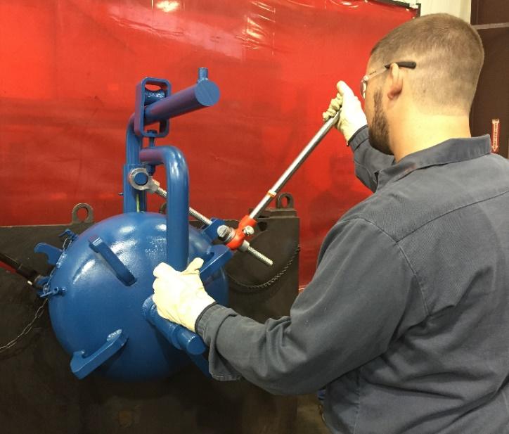
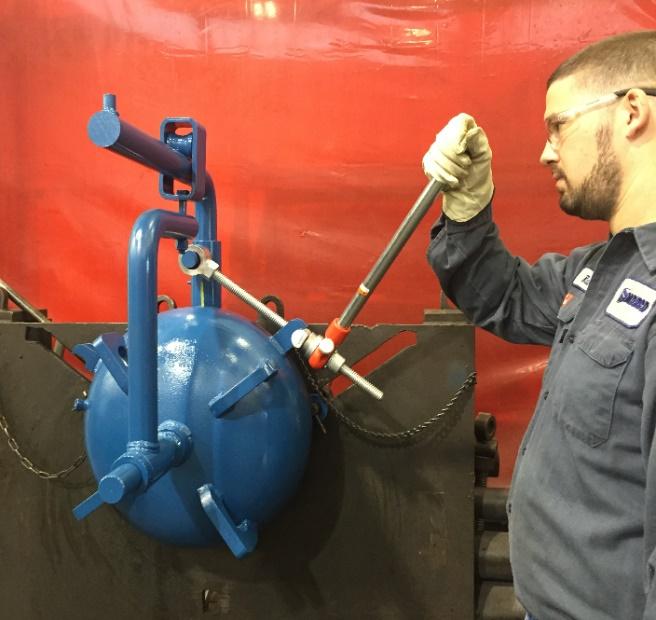
8 Part 1: Operation Instructions Opening the Figure 500 Closure a. Make certain all pressure has been safely bled from the vessel or pipeline. Attempting to open a closure without doing so could lead to a violent expulsion of pressure resulting in injury or death. b. Remove the Pressure Alert Valve (PAV) stem, if so equipped, and screw it into the retainer on the cap. The PAV is used to alert the operator of residual pressure in the vessel or pipeline. Unrelieved pressure can cause severe injury or death. If residual pressure is indicated, replace the PAV stem and ensure the vessel or pipeline is bled of all pressure. Do NOT use the PAV to bleed pressure from the vessel. NOTE: The Pressure Alert Valve (PIC #1) is standard on all 6 inch and larger closures. The PAV may not be present on two, three, or four inch closures as it is an option on these sizes on non ASME code stamp closure. PIC #1 c. Check for reference marks indicating the closed position of the cap and hub (PIC#2&3). If none are present, make a temporary mark across the cap and hub (PIC#4), then follow the instruction in the First Time Start Up section of this manual. d. Rotate the cap counter-clockwise with the lug wrench or ratchet tool provided (PIC#5). Do not use a hammer to open the cap. Hammering will deform the lugs on the cap and possibly lead to cracking in the cap or injuries. e. Rotate the cap until it is free of the hub. Then swing the cap to the side to gain access to the vessel or pipeline. IMPORTANT: For the safety of the operator and other crew members, stand to the side of the closure when opening the cap. Do not stand directly in front of the closure when opening (PIC#6 wrong & PIC#7 correct). Closing the Figure 500 Closure a. Align the cap to the hub and rotate clockwise. Tighten the cap with a lug wrench or ratchet tool until your reference marks line up (PIC#2,3&4). The reference marks indicate a metal to metal contact of the cap and hub sealing surface. b. On closures with a PAV, replace and tighten the PAV stem into the PAV body hand tight. Do not use tools to tighten the PAV, damage to the PAV may result. IMPORTANT: The cap will tighten sufficiently with the included lug wrench or ratchet tool. Overtightening the cap will result in damage to the threads and sealing surfaces of the cap. Do not use a hammer to tighten the closure. Page 2 of 10


9 PIC #2 PIC #3 PIC #4 PIC #5 PIC #6 PIC #7 Page 3 of 10
10 First Time Start up a. Open the closure as shown in the section Opening a Figure 500 closure. b. With the closure open, remove the O-ring and clean the sealing surfaces of the cap and hub removing all grease and debris. c. Apply a thin film of clean grease or Prussian Blue non-drying dye to the sealing surface of the cap. Carefully close the cap until it makes solid contact with the hub. Use caution to avoid over tightening or unnecessary force when mating the cap to the hub. The sealing surface of the hub and cap should now have metal to metal contact and cannot be tightened further. At this point, make permanent alignment marks on the cap and hub for future reference. d. Remove cap from hub and check for a clean and consistent transfer of grease or dye from the sealing face of the cap to the hub. If dye was used, clean it from the sealing surfaces now. Grease can remain on the closure. e. After verifying the condition of the closure and O-ring as described in Part 2 Maintenance Instructions, place the o-ring into the o-ring groove and make sure it is seated fully and not twisted. Apply lubricant to the threads and seal area of the closure. Use anti-galling lubricant, like light to medium lithium grease. Do not use silicone type grease. f. Close the cap until the alignment marks on the cap and hub return to their original positions. Use your ratchet tool or lug wrench if necessary to compress the O-ring. The closure should now have metal to metal contact between cap and hub with the O-ring in the groove and fully sealed. Take care not to over tighten the closure after all relative motion stops, or your reference marks line up. Overtightening may result in damage to closure or tightening tool. Proper adjustment of the Closure - Horizontal hinged closure a. 3-4 Horizontal Hinged closure: These closures are manufactured with no adjustment mechanism. No adjustment is necessary. b. Horizontal hinge closures 6 through 14 inch: Center the cap to hub using the vertical adjustment nut below the hinge arm (PIC#8&11). c. Horizontal closures 16 and larger: Vertical adjustment to center the cap to the hub is made by turning the adjustment nut located under the trolley assembly (PIC#8). Position the cap close to the hub to inspect parallel alignment. Adjustments are made by moving the hanger arm in or out along the cap pin. Important: Parallel Adjustment must to be made with the cap threaded on to the hub! Otherwise the cap may fall when the set collars are loose. If the cap is closer at the top of the hub, loosen the inside set collar (closure must be closed) and move the hanger arm in towards the cap. When parallel alignment has been achieved move the outer set collar in towards the cap accordingly. If the cap is closer at the bottom of the hub, loosen the outer set collar (closure must be closed) and move the hanger arm away from the cap (PIC#8). When parallel alignment has been achieved move the inner set collar away from the cap accordingly and tighten both set collars. Never leave the outer set collar loose! Note: Set collars may leave a bur on the cap pin due to the set screw in the collar. Remove the bur with a file or emery cloth to ease movement of the hanger arm. Page 4 of 10
11 Proper adjustment of the Closure - Vertical hinged closure a. 3-8 ANSI closures and ANSI closures: These closures are manufactured with no adjustment mechanism. No adjustment is necessary. b ANSI 900 closures: The cap should screw on to the hub with little to no thread drag. Use the adjustment bolt located in the bottom of the davit base (PIC#9) to lift or lower the cap to eliminate contact between the two components. c ANSI 300: The cap should screw on to the hub with no thread drag. Use the adjustment bolt located in the bottom of the davit base (PIC#9) to lift or lower the cap to eliminate contact between the two components. d. 24 ANSI 600 and larger: These closures feature both lateral and vertical adjustment Lateral Adjustment: Center the cap with the hub with the adjuster located on top of the davit arm adjustment sleeve (PIC#10). Be sure to tighten both sides of the adjuster when complete. Vertical Adjustment: Loosen the set screw in the pivot box assembly (PIC#10). Turn the vertical adjustment nut clockwise to raise the cap and counter-clockwise to lower the cap. Tighten the set screw after adjustments when checking the operation of the closure. Make only small adjustments and repeat as necessary to obtain minimal thread drag. PIC #8 PIC #9 & PIC #10 Page 5 of 10

12 Part 2: Maintenance and Inspection Maintenance Instruction Every time your Modco closure is opened, visually inspect the closure to ensure trouble free reliable service: a. Clean the closure threads, sealing surface, o-ring and o-ring groove. Remove grease and any debris from hub and inside the cap. b. If any cracks are found in the cap or hub, discontinue use and replace the component. c. Lubricate threads, sealing surface, cap pin bushing and hinge base. Lubricate the o-ring groove with a thin film of grease, just enough to support the o-ring to sink in to the o-ring groove smoothly. Use anti-galling lubricant, like light to medium lithium grease. Do not use silicone type grease. d. If adjustment to the vertical or horizontal hinge is needed, reference section Proper adjustment of the Closure. Inspection of the condition of the closure a. Inspect the O-ring for rough surfaces, nicks, or cuts. If any defects are found, replace it with an O-ring from Modco to ensure the dimensional integrity. Clean new or re-used O-rings, lubricate them lightly and place them in the O-ring groove. b. Procedure for thread inspection: NOTE: A thread gauge is available from Modco. It is a template with the five thread profiles used on Modco closures. The gauge allows the user to evaluate thread wear based on a visual comparison of the thread form between the gauge and the closure component. Find the thread profile that matches the threads on your closure and snugly insert the gauge. Inspect both the cap and hub for: - Galling, Gouges or nicks - Excessive wear/corrosion - Worn thread flanks - Rounded thread crests - Deformed thread profiles - Cracks, especially at the thread root. - Check the closure in at least four places on cap and hub. 12:00, 3:00, 6:00 & 9:00 positions are recommended Gauge handling Thread Gauge Page 6 of 10
13 Disassembly and reassembly of an installed closure Horizontal hinged closure a. Disassembly Locate the Pressure Alert Valve (PAV), remove the stem and screw it into the PAV retainer on the cap (PIC#11-14). The PAV is standard on all closures 6 and larger. Never attempt to open the closure while under pressure! Closures 6 to 14 : Open the closure (reference section Opening the Fig. 500 Closure ). While supporting the cap to prevent it from falling freely, remove the adjustment nut from the trolley assembly and safely lower the cap away from the closure. Lift the hinge components out of the base. Closures 16 to 48 : - Determine if the service to be performed requires opening the closure. The closure hinge components may be removed without opening the closure. - If the closure can remain closed, remove the outer set collar from the cap pin and slide the hanger arm away from the cap pin. Leave the inner set collar in place, this will retain the parallel balance set by the manufacturer. - Remove the vertical adjustment nut from the trolley assembly and safely lower the hanger arm off of the trolley. - Lift the hinge components from the hinge base. - If the closure needs to be open, reference section Opening A Figure 500 Closure. - Mark the position of the vertical adjustment nut. Place a lifting strap near the bend of the hanger arm. Make sure the set collars on the cap pin are secured. Lift slightly the cap and hanger arm together to facilitate removal of the vertical adjustment nut. - Remove the vertical adjustment nut and lower the cap and jib arm until they clear the trolley assembly. - Place the cap on a flat clean surface. Plywood or wooden pallets are preferred. - Lift the hinge components from the hinge base. If the closure is equipped with a dual wheel trolley, do not remove them from the jib arm. b. Assembly NOTE: Closures and up are equipped with a tapered roller bearing and a brass bushing on the jib post. Do not to damage these components during handling. NOTE: Prior closing the closure follow the section: Maintenance Instruction. - Insert the jib arm and trolley assembly into the hinge base. - If the cap was left on the closure, lift the hanger arm onto the trolley assembly and replace the saddle block (24 ANSI 600 and up) and vertical adjustment nut. - If the cap was removed, lift the cap and hinge arm onto the trolley assembly and replace the saddle block (24 ANSI 600 and up) and vertical adjustment nut. - Adjust the closure for proper operation (reference section Proper Adjustment of the Closure ). - Replace and tighten cap (reference section Closing the Figure 500 Closure ), replace the PAV stem into the PAV body and return the unit to service. Page 7 of 10
14 Disassembly and reassembly of an installed closure Vertical hinged closure a. Disassembly Locate the Pressure Alert Valve (PAV), remove the stem and screw it into the retainer on the cap (PIC#15-18). The PAV is standard on all closures 6 and larger. Never attempt to open the closure while under pressure! Closures 6 to 14 ANSI 900: Unscrew the cap until the cap pin bottoms out on the cap pin bushing. Lift the hinge components with the cap from the base. Closures 16 to 24 ANSI 300: Unscrew the cap until the cap pin bottoms out on the cap pin bushing. Attach a sling to a minimum of three cap ribs. Carefully lift the assembly until the davit arm is free of the base. Closures 24 ANSI 600 and larger: Unscrew the cap until the cap pin bottoms out on the cap pin bushing. Attach a sling to a minimum of three cap ribs. Carefully lift the assembly until the davit arm clears the base. NOTE: Make sure not to damage the tapered roller bearing and brass bushing on the davit arm during the handling. Place the cap face down on a clean level surface. Plywood or wooden pallets are preferred. b: Assembly NOTE: Follow the section Maintenance Instruction prior closing the closure. 6 to 14 closures: Insert Davit arm into base until fully seated. Screw the cap on. Replace the PAV stem into the PAV body. 16 to 24 ANSI 300: Insert davit arm into the base until fully seated. While closing the cap verify proper vertical adjustment (reference section vertical adjustment). Replace the PAV stem into the PAV body. 24 ANSI 600 and larger: Insert davit arm into the base. While screwing the cap onto the hub verify proper vertical and horizontal adjustment. The cap should screw down with no thread drag. If noticeable resistance is felt adjust the closure. Reference Section: Proper Adjustment of the Closure. Page 8 of 10
15 Page 9 of 10
16 CLOSURE SPECIALISTS SINCE 1981 MODCO INDUSTRIES, LLC FM 1484 Conroe, Texas, U.S.A (800) (936) Fax: (936) Page 10 of 10
Tool-less Hinged Closure Installation, Operation, & Maintenance
 2612 Howard Street Louisville, KY 40211 USA Phone 502-774-6011 Fax 502-774-6300 Website: www.tubeturns.com For genuine Tube Turns Closure parts please contact factory: ttaftermarket@sypris.com Bulletin
MODCO QUICK OPENING CLOSURES
 Figure 500 Threaded Closure Ⅰ Ⅱ Ⅲ MODCO QUICK OPENING CLOSURES If you are looking for a safe, reliable Quick Opening Closure, consider the proven Modco Figure 500. Modco provides an easy accessible, cost-efficient
INSTALLATION, OPERATION AND MAINTENANCE MANUAL
 INSTALLATION, OPERATION AND MAINTENANCE MANUAL LUDLOW SERIES FIGURE 340-S 3 to 14 Lever & Spring Swing Check Valves TABLE OF CONTENTS Introduction. 1 Description of Operation... 1 Receiving & Storage...
Maintenance Information
 16573370 Edition 2 February 2014 Air Grinder 99V Series Maintenance Information Save These Instructions Product Safety Information WARNING Failure to observe the following warnings, and to avoid these
AVK SAUDI VALVES MANUFACTURING COMPANY
 AVK SAUDI VALVES MANUFACTURING COMPANY AVK SERIES 24 - HIGH PRESSURE, WET BARREL HYDRANT FIELD MAINTENANCE AND INSTRUCTION MANUAL TABLE OF CONTENTS EXPLODED ASSEMBLY / PARTS LIST INTRODUCTION / DESCRIPTION
Installation Instructions
 Preparing your vehicle to install your brake system upgrade 1. Rack the vehicle. 2. If you don t have a rack, then you must take extra safety precautions. 3. Choose a firmly packed and level ground to
INSTALLATION, OPERATION AND MAINTENANCE MANUAL
 INSTALLATION, OPERATION AND MAINTENANCE MANUAL LUDLOW SERIES FIGURE 350-W 3 to 24 Lever & Weight Air-Cushioned Swing Check Valves TABLE OF CONTENTS Introduction. 1 Description of Operation... 1 Receiving
5000/6000 SERIES BALL VALVES INSTALLATION - MAINTENANCE MANUAL
 Date: August 2011 / Page 1 of 6 5000/6000 SERIES BALL VALVES INSTALLATION - MAINTENANCE MANUAL DESIGN The design features three piece construction and a free floating ball allowing ease of maintenance
Maintenance Information
 16572679 Edition 2 May 2014 Air Drill QP Series Maintenance Information Save These Instructions Product Safety Information WARNING Failure to observe the following warnings, and to avoid these potentially
DeZURIK MANUAL G-SERIES ACTUATOR USED ON PEF 100% PORT PLUG VALVES
 MANUAL G-SERIES ACTUATOR USED ON PEF 100% PORT PLUG VALVES Instruction D10456 August 2012 Manual G-Series Actuator used on Instructions These instructions provide information about Manual G-Series Actuators
SERVICE MANUAL L130B / L4130 Series Logstacker Drive Axle With Bolt-On Stub End Retainer
 SERVICE MANUAL L130B / L4130 Series Logstacker Drive Axle With Bolt-On Stub End Retainer Page 1 Allied Form #80-930 Rev 07/2009 SERVICE MANUAL LOG STACKER DA202 DRIVE AXLE TABLE OF CONTENTS PROCEDURE FOR
Maintenance Information
 16573347 Edition 2 February 2014 Air Grinder Series 88H Maintenance Information Save These Instructions Product Safety Information WARNING Failure to observe the following warnings, and to avoid these
Transmission Overhaul Procedures-Bench Service
 How to Assemble the Lower Reverse Idler Gear Assembly Special Instructions In 1996 Eaton changed the reverse idler system design. In the nut design, the reverse idler bearing was lubricated through a hole
AMERICAN AVK COMPANY AVK SERIES 24 - HIGH PRESSURE, WET BARREL HYDRANT FIELD MAINTENANCE AND INSTRUCTION MANUAL TABLE OF CONTENTS
 AMERICAN AVK COMPANY AVK SERIES 24 - HIGH PRESSURE, WET BARREL HYDRANT FIELD MAINTENANCE AND INSTRUCTION MANUAL TABLE OF CONTENTS EXPLODED ASSEMBLY / PARTS LIST INTRODUCTION / DESCRIPTION RECEIVING AND
INSTALLATION - MAINTENANCE MANUAL Severe Service Series M4 Ball Valve
 INSTALLATION - MAINTENANCE MANUAL Severe Service Series M4 Ball Valve Date: May 2016/ Page 2 of 12 Table of Contents 1. Safety Information - Definition of Terms..........................2 2. Bill of Materials....................................
2003 Dodge Pickup R DRIVE AXLES' 'Axle Shafts - Front - Ram Pickup WD DRIVE AXLES
 2002-04 DRIVE AXLES Axle Shafts - Front - Ram Pickup 1500 4WD DESCRIPTION Vehicles equipped with 4WD and C205F front axle assembly use equal length axle shaft system to deliver power from front differential
HEAVY DUTY TROLLEY JACK. Operation Manual
 HEAVY DUTY TROLLEY JACK 4T Operation Manual Make sure to read and fully understand the instruction manual before using this product and keep the manual properly 1 General Description Product Description
These instructions are applicable to the following models: ARI 1118 ARI 1148
 INSPECTION & MAINTENANCE BULLETIN ARI 1118 & 1148 Safety Relief Valve These instructions are applicable to the following models: ARI 1118 ARI 1148 Only AAR class F facilities are certified to recondition,
These instructions are applicable to the following models: ARI 1108 ARI HP1108
 INSPECTION & MAINTENANCE BULLETIN ARI 1108 & HP1108 Safety Relief Valve These instructions are applicable to the following models: ARI 1108 ARI HP1108 Only AAR class F facilities are certified to recondition,
COMMERCIAL. BV & BVM Series Installation Instructions 06/29/15
 COMMERCIAL Bray Controls Commercial Division 13788 West Road, Suite 00A Houston, Texas 77041 BCDSales@Bray.com Phone: 1-888-41-79 Fax: 1-888-41-70 www.braycommercialdivision.com BV & BVM Series Installation
»Product» Safety Warning
 #F1420 Installation Instructions 2011 Ford Super Duty F250/350 4wd 4" Suspension Lift Read and understand all instructions and warnings prior to installation of product and operation of vehicle. Zone Offroad
LIMITED SLIP DIFFERENTIAL INSTALLATION
 Installation of the limited slip gear can be done with axle out of car or with car lifted to gain access from underneath. Refer to repair manual for proper lifting instructions if car is to be lifted.
Quick Opening Closure Operating Instructions
 Quick Opening Closure Operating Instructions To prevent SERIOUS INJURY and PROPERTY DAMAGE, you should read, understand and follow these Operating Instructions. Keep for future reference. 1 Safety Information
TABLE OF CONTENTS. 3 Outlet Stainless Steel Body. 3 Outlet Ductile Body. 2 Outlet Ductile Body 2 Outlet Bronze Body
 AVK SERIES 24 - HIGH PRESSURE, WET BARREL HYDRANT FIELD MAINTENANCE AND INSTRUCTION MANUAL TABLE OF CONTENTS EXPLODED ASSEMBLY / PARTS LIST INTRODUCTION / DESCRIPTION RECEIVING AND STORAGE INSTALLATION
Maintenance Instructions. World Leader in Modular Torque Limiters. JSE AEA Extruder Clutch
 World Leader in Modular Torque Limiters PROTECTING EQUIPMENT& MACHINERYYEARSInstallation and Maintenance Instructions JSE.5-0234AEA Extruder Clutch 1304 Twin Oaks Street Wichita Falls, Texas 76302 (940)
Maintenance Information
 04581245 Edition 2 May 2014 Air Grinder, Die Grinder and Sander Series G2 (Angle) Maintenance Information Save These Instructions Product Safety Information WARNING Failure to observe the following warnings,
McCannalok HIGH PERFORMANCE BUTTERFLY VALVE OPERATION AND MAINTENANCE MANUAL. The High Performance Company
 McCannalok HIGH PERFORMANCE BUTTERFLY VALVE OPERATION AND MAINTENANCE MANUAL The High Performance Company Table of Contents Safety Information - Definition of Terms... 1 Introduction... 1 Installation...
TECHNICAL BULLETIN. TP Issued Servicing Rockwell s TB Series Trailer Axles with Unitized Hub Assemblies
 TECHNICAL BULLETIN TP-96175 Issued 12-96 Servicing Rockwell s TB Series Trailer Axles with Unitized Hub Assemblies TB Series Trailer Axles Introduction Rockwell s TB series trailer axle features a permanently
servicing the swivel
 servicing the swivel The swivel seals and bearings require periodic replacement. This document describes how to determine which service procedure to use to service the swivel assembly, part number 101110.
COYOTE ENTERPRISES, INC. 9/10 BLAST WHEEL MAINTENANCE & ASSEMBLY MANUAL
 COYOTE ENTERPRISES, INC. 9/10 BLAST WHEEL MAINTENANCE & ASSEMBLY MANUAL Parts & Machinery for the Abrasive Blast Industry 27301 East 121st Street Coweta, Oklahoma 74429 (918) 486-8411 Fax (918) 486-8412
SM64052 Maintenance & Repair Manual Commercial 2" Unisex Coupling - Valved Model 64052
 Aerospace Group Conveyance Systems Division Carter Brand Ground Fueling Equipment SM64052 July 2004 Applicable additional manuals: SM64051 Commercial 2" Unisex Coupling, Non-Valved Maintenance & Repair
PV4 - Compact Shut Off Style Pig Valve IOM - Installation, Operation & Maintenance
 ACECO Valve P.O. Box 9 Mounds, Oklahoma 74047 PV4 - Compact Shut Off Style Pig Valve IOM - Installation, Operation & Maintenance Doc. No.: IOM-PV4-.0 Date: 6/0-00 Revision: A Contents: Installation Operation
Racing Jack Max. Capacity: 3,000 lbs. (1,361 kg)
") R SPX Corporation 655 Eisenhower Drive Owatonna, MN 55060-0995 USA Phone: (507) 455-7000 Tech. Serv.: (800) 533-6127 Fax: (800) 955-8329 Order Entry: (800) 533-6127 Fax: (800) 283-8665 International Sales:
R SPX Corporation 655 Eisenhower Drive Owatonna, MN 55060-0995 USA Phone: (507) 455-7000 Tech. Serv.: (800) 533-6127 Fax: (800) 955-8329 Order Entry: (800) 533-6127 Fax: (800) 283-8665 International Sales:
Before installation these instructions must be fully read and understood
 Before installation these instructions must be fully read and understood Yoke bushing Split gland bushing One-piece body with accessible internals Gland Swing bolts Fully retractable stellite disc Figure
ABI WHEEL & BRAKE KIT
 INSTALLATION INSTRUCTIONS and INSTRUCTIONS FOR CONTINUED AIRWORTHINESS for the installation of ABI-199-62 WHEEL & BRAKE KIT for CESSNA AIRCRAFT SERIES 180, 185, 206 Doc No.: ABI-199-62-4 REV B 04/21/2017
DeZURIK " BAW AWWA BUTTERFLY VALVES WITH EPOXY-RETAINED SEAT
 DeZURIK 20 144" BAW AWWA BUTTERFLY VALVES WITH EPOXY-RETAINED SEAT Instruction D10373 April 2017 Instructions These instructions provide information about the 20 (250 F2 model only) and the 24-144 BAW
GH-BETTIS OPERATING & MAINTENANCE INSTRUCTIONS DISASSEMBLY & ASSEMBLY FOR THE T80X-M4-S DOUBLE ACTING SERIES HYDRAULIC ACTUATORS
 GH-BETTIS OPERATING & MAINTENANCE INSTRUCTIONS DISASSEMBLY & ASSEMBLY FOR THE T80X-M4-S DOUBLE ACTING SERIES HYDRAULIC ACTUATORS -S INDICATES CYLINDERS ARE IN TANDEM PART NUMBER: 100121 REVISION "A" ECN
LJ20 Distributor - Disassembly Inspection Repair
 LJ20 Distributor - Disassembly Inspection Repair Old Codger New To Old Suzuki Jeeps The odometer on this 1972 LJ20 indicated the distributor had less than 10,000 miles of wear but during that time it had
INSTALLATION INSTRUCTIONS
 INSTALLATION INSTRUCTIONS FRONT DISC BRAKE CONVERSION KITS A148-9 & A148-15 1949-54 Chevy Trucks Thank you for choosing STAINLESS STEEL BRAKES CORPORATION for your braking needs. Please take the time to
Installation Notes: #86000-R Race Series +3.5 L/T Kit
 159 North Maple St. Unit J, CORONA CA 92880 P. 951-737-9682 F. 951-737-9006 WWW.CHAOSFAB.COM Installation Notes: #86000-R Race Series +3.5 L/T Kit Factory manual is recommended for removal and re-installation
 DRUM BRAKE RIMS Periodic inspection of drum brake rims is necessary to determine indications of uneven or excessive wear. In general, brake rim failures other that regular wear are caused by brake linings
PNEUMATIC SLIDING VALVE
 INSTALLATION, OPERATION, & #: MM-SV001 6-23-09 Rev. A Page 1 of 8 PNEUMATIC SLIDING VALVE PART NUMBERS (Including, but not inclusive) SV704MSTS, SV714MSTS, SV754MSTS, SV764MSTS, SV774MSTS, SV706MSTS, SV716MSTS,
INSTALLATION, OPERATION AND MAINTENANCE FOR SERIES 500 K-FLO BUTTERFLY VALVES
 INSTALLATION, OPERATION AND MAINTENANCE FOR SERIES 500 K-FLO BUTTERFLY VALVES PO Box 411 Berwick PA 18603 800-247-VALV www.crispinvalve.com Product Introduction -- K-FLO Series 500: 3 --20 Introduction
Operation & Maintenance Manual 4900 Series Pipeline Injection Pumps Bulletin 150
 340 West Benson Avenue Grantsburg, WI 54840 1-800-366-1410 715-463-5177 www.northern-pump.com Table of Contents Introduction... 3 Rotation... 4 Hydraulic Balance... 5 Cautionary Statements... 6 Pump Installation...
CROWERGLIDE AUTOMATIC CLUTCH Instruction Manual
 CROWERGLIDE AUTOMATIC CLUTCH Instruction Manual Crower Cams & Equipment Co., Inc 6180 Business Center Court San Diego, CA. 92154 Phone: 619.661.6477 ext. 148 Fax: 619.690.7846 www.crower.com TABLE OF CONTENTS
Maintenance Information
 16573321 Edition 3 February 2014 Air Grinder Series 61H Maintenance Information Save These Instructions Product Safety Information WARNING Failure to observe the following warnings, and to avoid these
1988 Chevrolet Pickup V SUSPENSION - FRONT (4WD)' 'Front Suspension - "V" Series 1988 SUSPENSION - FRONT (4WD) Front Suspension - "V" Series
' 'Front Suspension - V Series 1988 SUSPENSION - FRONT (4WD) Front Suspension - V Series") 1988 SUSPENSION - FRONT (4WD) Front Suspension - "V" Series DESCRIPTION NOTE: Vehicle serial numbers used in this article has been abbreviated for common reference to Chevrolet and GMC models. Chevrolet
1988 SUSPENSION - FRONT (4WD) Front Suspension - "V" Series DESCRIPTION NOTE: Vehicle serial numbers used in this article has been abbreviated for common reference to Chevrolet and GMC models. Chevrolet
This file is available for free download at
 This file is available for free download at http://www.iluvmyrx7.com This file is fully text-searchable select Edit and Find and type in what you re looking for. This file is intended more for online viewing
»Product» Safety Warning
 #F1424 Installation Instructions 2011 Ford Super Duty F250/350 4wd 4" Radius Arm Suspension Lift Read and understand all instructions and warnings prior to installation of product and operation of vehicle.
Sachs 48mm Closed Cartridge fork Service Manual
 Sachs 48mm Closed Cartridge fork Service Manual 1 Fork seal driver 2 Special soft jaws 3 Fork cap wrench 4 Rebound rod holding tool 5 Compression assembly holding tool 6 Retaining clip tool Special Tools
OPERATION SERVICE PARTS Manually Operated Lever Hoist
 OPERATION SERVICE PARTS Manually Operated Lever Hoist With 21 Handle A3134-XXX A3191-XXX A3192-XXX MA8196-XXX (with special attachments) MA8206-XXX (with special attachments) A3195-XXX MA8195-XXX (with
FORM NO GB Rev A OPERATOR S MANUAL MODEL NO & UP MODEL NO & UP REELMASTER 5100 CUTTING UNIT
 FORM NO. 3318-294 GB Rev A MODEL NO. 03505 60001 & UP MODEL NO. 03508 60001 & UP OPERATOR S MANUAL REELMASTER 5100 CUTTING UNIT The TORO COMPANY 1991, Rev. 1992, 1993, 1994 Table of Contents Page No. SPECIFICATIONS
Northern Pump A Division of McNally Industries, LLC
 Operation & Maintenance Manual for Northern 4900 Injection Operation & Maintenance Manual For Northern 4900 Injection Northern Pump A Division of McNally Industries, LLC 340 West Benson Avenue Grantsburg,
HORSTMAN GREASED LIGHTNING CLUTCH
 HORSTMAN GREASED LIGHTNING CLUTCH Horstman s Greased Lightning (GL) clutch is designed for ultra high performance, and requires expert setup and a serious commitment to maintenance. Warning!!! 1. Clutch
TECHNICAL SERVICE MANUAL
 TECHNICAL SERVICE MANUAL HEAVY-DUTY bracket mounted PUMPS SERIES 4193 AND 493 SIZES GG - AL SECTION TSM 154 PAGE 1 of 10 ISSUE C CONTENTS Introduction....................... 1 Special Information...................
Butterfly Valve Type 58 (PDCPD)
") Serial No. H-V074-E Butterfly Valve Type 58 (PDCPD) 700mm (28 ) User s Manual Contents (1) Be sure to read the following warranty clauses of our product 1 (2) General operating instructions 2 (3) General
Serial No. H-V074-E Butterfly Valve Type 58 (PDCPD) 700mm (28 ) User s Manual Contents (1) Be sure to read the following warranty clauses of our product 1 (2) General operating instructions 2 (3) General
Bag 1. Bag 1. Center Pivot. Center Pivot
 8 00734 01901 5 Center Pivot Bag 1 3374 - Center Pivot Socket 4019 - Alum Pivot ball 3254-2-56 Button Head *Note - Sometimes it is helpful to slightly over-tighten the top clamp screws, then work the ball
»Product» Safety Warning
 #F1422 Installation Instructions 2008-2010 Ford Super Duty F250/350 4wd 4" Radius Arm Suspension Lift Read and understand all instructions and warnings prior to installation of product and operation of
OPERATION AND PARTS MANUAL
 OPERATION AND PARTS MANUAL MODEL NUMBER : PART NUMBER : GTL 1110 1900-0510 SERIAL NUMBER : BAYNE MACHINE WORKS, INC. PHONE: (864) 288-3877 910 FORK SHOALS ROAD TOLL FREE: (800) 535-2671 GREENVILLE S.C.,
MAINTENANCE MANUAL. Drivelines MM Edition october/11
 MAINTENANCE MANUAL Drivelines MM-96147 Edition october/11 Index 1 - Drivelines... 03 2 - Introduction... 05 3 - Inspection... 06 4 - RPL Series PermalubeTM... 12 5 - Full-Round... 23 6 - Wing-Style PermalubeTM...
BETTIS SERVICE INSTRUCTIONS DISASSEMBLY AND REASSEMBLY FOR CB-SR-S SEISMIC SPRING RETURN SERIES PNEUMATIC ACTUATORS
 BETTIS SERVICE INSTRUCTIONS DISASSEMBLY AND REASSEMBLY FOR CB-SR-S SEISMIC SPRING RETURN SERIES PNEUMATIC ACTUATORS PART NUMBER: 102264 REVISION: "C" DATE: November 2000 Page 1 of 11 1.0 INTRODUCTION 1.1
Butterfly Valve Type 57P
 Butterfly Valve Type 57P Contents Lever Type: 50-200 mm (2-8 ) Body Material: CPVC Gear Type: 50-200mm (2-8 ) Body Material: CPVC (1) Be sure to read the following warranty clauses of our product 1 (2)
Maintenance Information
 80234313 Edition 2 May 2014 Air Grinder, Die Grinder, Sander and Belt Sander Series G1 (Angle) Maintenance Information Save These Instructions Product Safety Information WARNING Failure to observe the
Hydraulic Wheel Dolly
 Hydraulic Wheel Dolly Operating Instructions & Parts Manual Model Number HW93766 Capacity 3/4 Ton Made in the U.S.A. This is the safety alert symbol. It is used to alert you to potential personal injury
Maintenance & Repair Manual
 SM64055 November 2012 Aerospace Group Conveyance Systems Division Applicable additional manuals: None Carter Brand Ground Fueling Equipment Maintenance & Repair Manual 4 Inch Internal/Bottom Loading Valves
Mechanical Actuators
 Mechanical Actuators Translating Machine Screw Actuators 100-Ton, 150-Ton & 250-Ton Capacity Installation, Operation & Maintenance Instructions Publication Part No. SK-2389-100 CAUTION This manual contains
FRONT FORK 2.16 GENERAL REMOVAL HOME. 4. See Figure Loosen upper and lower fork clamp pinch fasteners (1, 4).
.") FRONT FORK.6 GENERAL The XRScg model utilizes a mm fork assembly while all other models have changed to the mm fork assembly. The front fork consists of two telescoping outer tube/inner slider assemblies.
FRONT FORK.6 GENERAL The XRScg model utilizes a mm fork assembly while all other models have changed to the mm fork assembly. The front fork consists of two telescoping outer tube/inner slider assemblies.
Char-Lynn Hydraulic Motor. Repair Information Series. April, 1997
 Char-Lynn Hydraulic Motor April, 1997 Repair Information Geroler Motors 002 00 004 Parts Drawing 1 See Note 2 Page 1 22 1 9 1-1/4 Split Flange Ports 8 7 6 5 B 1 See Note 2 Page 2 24 4 14 19 20 15 1 18
Instruction Manual for HSPA Take-Up Units
 Installation Instruction Manual for HSPA Take-Up Units Warning: To ensure the drive is not unexpectedly started, turn off and lockout the power source before proceeding. Failure to observe these precautions
INSTRUCTIONS CONTINUED AIRWORTHINESS
 INSTRUCTIONS FOR CONTINUED AIRWORTHINESS FOR GROVE MAIN WHEEL AND BRAKE ASSEMBLIES WITH FAA-TSO APPROVAL DOCUMENT 13046-11 Rev C April 29, 2018 TABLE OF CONTENTS SECTION PAGE Title Page... 1 Table of Contents...
YOUR GLOBAL FLOW CONTROL PARTNER. BRAY/MCCANNALOK EN High Performance Butterfly Valve Operation and Maintenance Manual
 YOUR GLOBAL FLOW CONTROL PARTNER BRAY/MCCANNALOK EN High Performance Butterfly Valve TABLE OF CONTENTS 1.0 Definition of Terms....................................... 2 2.0 Introduction...........................................
IMOI 2010 Rev 0
 FOREWORD The following instructions are offered as a reference aid to the valve user when installing, maintaining or operating Williams Gate, Globe and Swing Check valves. This document, consisting of
Keystone Series GR resilient seated butterfly valves GRW/GRL Installation and operation manual
 Before installation these instructions must be fully read and understood Important Before valves are installed or used the following actions are recommended. 1. Valves/parts have to be inspected and thoroughly
MEMORY SEAL BALL VALVES MAINTENANCE MANUAL 2 12, Class 150 & 300, Regular Port, Flanged Unibody
 MEMORY SEAL BALL VALVES MAINTENANCE MANUAL 2 12, Class 150 & 300, Regular Port, Flanged Unibody I INTRODUCTION These rugged, versatile, high performance, regular port, ball valves meet all requirements
GEN-3 Super-duty Supercharger Shaft Kit PART# - RY17040-UK-6S5-3
 GEN-3 Super-duty Supercharger Shaft Kit PART# - RY17040-UK-6S5-3 We strongly recommend the use of a service manual to familiarize yourself with the various components and procedures involved with this
Firehawk Second Stage Regulator Fire Service
 Firehawk Second Stage Regulator Fire Service MAINTENANCE AND REPAIR TAL 1701 (L) Rev. 2 MSA 2017 Prnt. Spec. 10000005389(I) Mat. 10147454 Doc. 10147454 TAL 1701 (L) Rev. 2-10147454 2 NON-CBRN FIREHAWK
70001 and Clutch Rebuild Instructions
 70001 and 70010 Clutch Rebuild Instructions Brinn, Incorporated 1615 Tech Drive Bay City, MI 48706 Telephone 989.686.8920 Fax 989.686.6520 www.brinninc.com Notice Use these instructions if you only want
Bray/McCannalok High Performance Butterfly Valve Operation and Maintenance Manual
 Bray/McCannalok High Performance Butterfly Valve Operation and Maintenance Manual Table of Contents Definition of Terms 1 Introduction 1 Installation 1 Maintenance 2 Stem Seal Replacement 4 Seat Replacement
Audi B6/B7 A4/S4 Rear Wheel Bearing Service Kit
 Audi B6/B7 A4/S4 Installation Tutorial ES2561175 This tutorial is provided as a courtesy by ECS Tuning. Proper service and repair procedures are vital to the safe, reliable operation of all motor vehicles
INSTALLATION INSTRUCTIONS Mopar Performance 2 Lift System 2009 and Newer Dodge Ram 1500 (DS) 4WD PART NUMBER P
 4WD PART NUMBER P") INTRODUCTION Installation requires a professional mechanic. Prior to beginning, inspect the vehicle s steering, driveline, and brake systems, paying close attention to the suspension link arms and bushings,
INTRODUCTION Installation requires a professional mechanic. Prior to beginning, inspect the vehicle s steering, driveline, and brake systems, paying close attention to the suspension link arms and bushings,
Low Profile Service Jack Jack Stand Combo
 Low Profile Service Jack Jack Stand Combo Jack Stands Low Profile Service Jack U.S. Patent No. 6,199,379! This is the safety alert symbol. It is used to alert you to potential personal injury hazards.
Operating & Maintenance Manual For Steam Conditioning Valve
 For Steam Conditioning Valve 1 Table of Contents 1.0 Introduction 3 2.0 Product description 3 3.0 Safety Instruction 4 4.0 Installation and Commissioning 5 5.0 Valve Disassembly 6 6.0 Maintenance 6 7.0
Provided by: Operating, Maintenance & Parts Manual
 Provided by: www.hoistsdirect.com TB681.qxd 11/29/2004 3:04 PM Page 1 Operating, Maintenance & Parts Manual TB603 Manually Lever Operated Chain Hoist 1100 POUNDS MAXIMUM CAPACITY (500 kg) Follow all instructions
KEYSTONE. Butterfly valves Figure 9 Installation & Maintenance Instructions. Please read these instructions carefully
 KEYSTONE Please read these instructions carefully This symbol indicates important messages and safety instructions. Hazard potentials: disregarding of instructions improper use of product insufficiently
1984 Dodge W250 PICKUP
 1984 Dodge W250 PICKUP Submodel: Engine Type: V8 Liters: 5.2 Fuel Delivery: CARB Fuel: GAS Dana 44 MODELS THROUGH 1984 2. Raise and safely support the vehicle, then remove the wheel hub and bearings as
TECHNICAL SERVICE MANUAL
 Electronic copies of the most current TSM issue can be found on the Viking Pump website at www.vikingcom TECHNICAL SERVICE MANUAL abrasive liquid pumps SERIES 4625 SIZES f - fh SECTION TSM 410.1 PAGE 1
PRODUCT OBSOLETED 4Q16
 Electronic copies of the most current TSM issue can be found on the Viking Pump website at www.vikingcom TECHNICAL SERVICE MANUAL abrasive liquid pumps SERIES 4625 SIZES f - fh SECTION TSM 410.1 PAGE 1
Fisher 657 Diaphragm Actuator Sizes and 87
 Instruction Manual 657 Actuator (30-70 and 87) Fisher 657 Diaphragm Actuator Sizes 30 70 and 87 Contents Introduction... 1 Scope of Manual... 1 Description... 2 Specifications... 2 Installation... 3 Mounting
Installation Instructions
 Instructions Created by an: Inchworm Gear Clockable Toyota Dual Transfer Case Adapter Kit, 21 or 23 Spline SKU# TCASE-IW-300-000 Installation Instructions CAUTION: Safety glasses should be worn at all
Superlift Leveling System / 6 Upgrade System for 2004 and Newer Ford F-150 4WD INSTALLATION INSTRUCTIONS
 FORM #9905.02-032907 PRINTED IN U.S.A. PAGE 1 OF 7 INTRODUCTION Superlift 0.5-2 Leveling System / 6 Upgrade System for 2004 and Newer Ford F-150 4WD INSTALLATION INSTRUCTIONS Installation requires a professional
Operation & Maintenance Manual For 4900 Series Pumps Bulletin 134
 For 340 West Benson Avenue Grantsburg, WI 54840 1-800-366-1410 715-463-5177 www.northern-pump.com Table of Contents Introduction... 3 Cautionary Statements... 5 Pump Installation... 6 Removal from Installation...
AVK SERIES 41 SWING CHECK VALVE FIELD MAINTENANCE AND INSTRUCTION MANUAL FOR SWING CHECK VALVES 3" - 12"
 AMERICAN AVK COMPANY AVK SERIES 41 SWING CHECK VALVE FIELD MAINTENANCE AND INSTRUCTION MANUAL FOR SWING CHECK VALVES 3" - 12" TABLE OF CONTENTS EXPLODED ASSEMBLY / PARTS LIST INTRODUCTION / DESCRIPTION
Sachs shock manual. ( ) 2 & 4 Stroke RR Enduro. ( ) RS Dual Sport
 2 & 4 Stroke RR Enduro. ( ) RS Dual Sport") Sachs shock manual (2013 2015) 2 & 4 Stroke RR Enduro (2014-2015) RS Dual Sport 1 Introduction The procedures in this manual must take place in a clean environment using professional tools and some specific,
Sachs shock manual (2013 2015) 2 & 4 Stroke RR Enduro (2014-2015) RS Dual Sport 1 Introduction The procedures in this manual must take place in a clean environment using professional tools and some specific,
DeZURIK M-SERIES MANUAL ACTUATOR
 M-SERIES MANUAL ACTUATOR Instruction D10287 February 2017 Instructions These instructions provide information about Manual s. They are for use by personnel who are responsible for installation, operation
Hyponic. Quick-Start Guide. Manual
 Hyponic Quick-Start Guide 1 Manual 12.002.61.008 Hyponic Safety Consult the factory if Hyponic products are driven by DC motors, variable frequency AC drives, or speeds other than standard catalog input
Installation, Operating and Maintenance Instructions. Rotating Machine Screw Actuators. With Parts List Publication Part No.
 Installation, Operating and Maintenance Instructions With Parts List Publication Part No. SK-2389-R1 Rotating Machine Screw Actuators 1/4 Through 1-Ton Capacity Caution This manual contains important information
Sport Model with an easy-lube spindle
 1. List of tools: Back To Top 1. Safety glasses 2. Hammer 3. Brass or aluminum punch 4. channel locks 5. Block of wood or plastic 6. grease gun 7. razor knife 8. 6" long, 2" diameter or 1 ½" diameter pipe
CRANKSHAFT & MAIN BEARINGS
 CRANKSHAFT & MAIN BEARINGS * PLEASE READ THIS FIRST * REMOVAL Ensure all main bearing caps are marked for location on cylinder block. Some main bearing caps have an arrow stamped on them. The arrow must
INSTRUCTION MANUAL. Anchor Darling 1878 Swing Check Valves. Installation Operation Maintenance. Sizes 1/2 through 2 FCD ADENIM
 INSTRUCTION MANUAL Anchor Darling 1878 Swing Check Valves Sizes 1/2 through 2 Installation Operation Maintenance FCD ADENIM0006-00 Table of Contents 1.0 Physical Description and Operation of Equipment
Air-Assist Service Jack Max. Capacity: 10 Tons
 Form No. 565786 Parts List & Operating Instructions for: 1511B Air-Assist Service Jack Max. Capacity: 10 Tons 109 67 66 68 77 69 70 78 95 94 107 106 108 26 71 72 72 93 X L 65 75 92 91 90 89 88 87 86 85