for ½" thru 2" 800 lb. Piston Lift Check Valves with Resilient Seat Option
|
|
|
- Dale Pope
- 6 years ago
- Views:
Transcription
 832-0525 FAX: (919) 831-3369")
1 Manual No. 800-PC Issued: March 31, 2004 INSTRUCTION MANUAL for ½" thru 2" 800 lb. Piston Lift Check Valves with Resilient Seat Option Flowserve Corporation Flow Control Division 1900 S. Saunders Street P.O. Box 1961 Raleigh, NC Phone: (919) FAX: (919)
2 Table of Contents 1.0 Physical Description and Operation of Equipment 2.0 Design Conditions 3.0 Operating Conditions 4.0 Test Conditions 5.0 Operating Precautions and Limitations 6.0 Installation Instructions 7.0 Maintenance Requirements 8.0 Periodic Inservice Testing Recommendations and Procedures 9.0 Maintenance Instructions 10.0 Storage Requirements 11.0 Reference Drawings
3 Manual No. 800-PC Revision Sheet Revision Date Changes - 03/31/2004 Original Issue
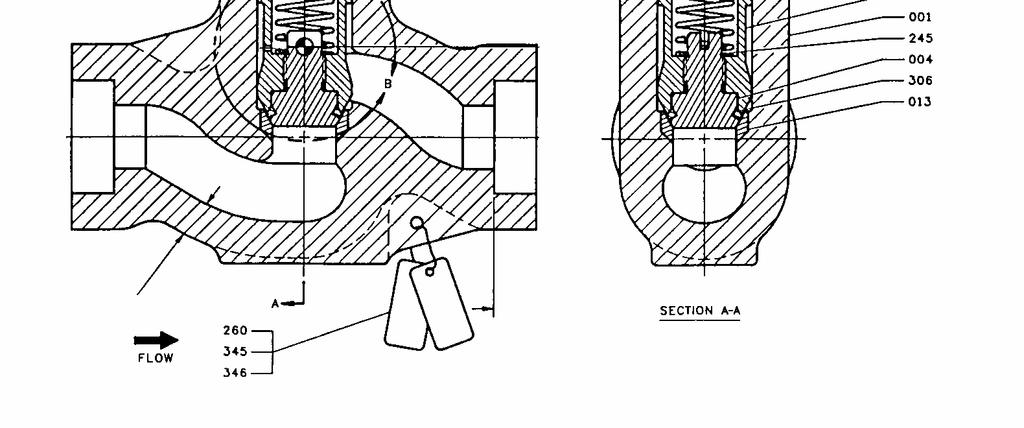
4 1.0 PHYSICAL DESCRIPTION AND OPERATION OF EQUIPMENT 1.1 Piston Check Valves (Figures 1 & 2 - See Section 11.0) Piston Lift Check valves are generally used in applications where pressure drop through the valve is not critical, although Flowserve piston check valves have a relatively low pressure drop. These small piston lift check valves include a return spring to facilitate closing. All Flowserve piston check valves have body guided discs to provide resistance to wear, thus, insuring a longer life. An equalizing hole is provided in the disc as a drain for condensate in steam valves. A dual seat may be supplied which provides a hard surface for high differential pressure sealing and a resilient seat for sealing during low differential pressure. These instructions are being furnished to the customer for use in the installation, operation and maintenance of the 800 pressure class series piston lift check valves. 2.0 DESIGN CONDITIONS N/A 3.0 OPERATING CONDITIONS N/A 4.0 TEST CONDITIONS 4.1 Each valve covered by this manual has received the following hydrostatic tests: Shell hydrostatic test at 1.5 times the 100 F pressure rating A seat leakage and disc closure test at 110% of the 100 F pressure rating.
5 4.0 TEST CONDITIONS (Continued) 4.2 Each valve, supplied with resilient seated discs, received the following hydrostatic tests: A low-pressure water seat test at 50 psig for containment isolation valves. 5.0 OPERATING PRECAUTIONS AND LIMITATIONS 5.1 Maximum hydrostatic test pressure shall not exceed the values imposed by the ASME Code, Section III. 6.0 INSTALLATION INSTRUCTIONS 6.1 Lifting and Handling Requirements and Limitations Good judgement should be exercised in selecting a lifting device that will safely support the unit's weight Remove the end covers Remove any blocks or heavy paper that might have been used to keep the disc from moving during shipment. 6.2 Installation Although the valves have been shipped in a clean condition, prior to installing the valves, examine the lines and the valve ports for foreign matter and clean them thoroughly if they have been exposed to the elements. (BEFORE CLEANING IN THIS FASHION, CHECK AT THE SITE TO SEE IF A SPECIFIC CLEANING PROCEDURE SHOULD BE FOLLOWED.) Flush the valves out with water if possible; otherwise blow them out with air or steam. In performing this cleaning procedure, the ports should be vertical to assure complete removal of all matter which might have accumulated during storage Ensure that there is no line sag at the point of installation. Eliminate any pipeline deviation by the proper use of pipeline hangers or similar device.
6 6.2 Installation (Continued) Extreme caution should be taken when installing check valves. The arrow on the valve body indicates flow direction. Therefore, when installing a check valve, place it so that the flow of the incoming fluid will open the valve and return flow will close it. Check valves installed in reverse position will stop the flow in the normal flow direction. Valves should be installed in a horizontal run of pipe with the gasket retainer on top. Maximum deviation from the horizontal should be ± The valves should then be blocked or slung into position with apparatus that is sufficient to hold the valve assembly weight while the valve is being welded into the line. WELDING SHOULD TAKE PLACE WITH THE DISC IN THE OPEN POSITION. This is particularly important for valves with soft seats. Welding the valve with the disc closed will damage the resilient seat material. This may require removal of the internals prior to welding Remove the end protectors and clean the ends with a solvent such as acetone in preparation to welding. 7.0 MAINTENANCE REQUIREMENTS 7.1 Preventative Maintenance Check all bolts periodically to ensure tightness and to forestall possible leaks. 7.2 Recommended Spare Parts Recommended spare parts are pressure seal gasket (030), bonnet (002), disc assembly (004 & 005, 245 & 306 if equipped with resilient seated disc) and spring (429). The recommended quantity is 1 set for every 10 valves For consolidating spare parts (See 7.2.1), use the following guidelines: - ½" thru 1" Piston Check Valves Recommended spare parts are interchangeable throughout this size range. Note that similar materials should be ordered for valve body type (i.e. carbon steel bonnet for carbon steel valve).
7 7.0 MAINTENANCE REQUIREMENTS (Continued) 7.3 Lubrication - 1½" and 2" Reduced Port Piston Check Valves Recommended spare parts are interchangeable throughout this size range. Note that similar materials should be ordered for valve body type (i.e. carbon steel bonnet for carbon steel valve). - 2" Full Port Piston Check Valves Recommended spare parts are only interchangeable with other 2" Full Port Piston Check Valves. Same material restrictions stated above apply A light coating of lubricant should also be applied to the bonnet retainer threads if and when the valve is reassembled. 8.0 PERIODIC INSERVICE TESTING RECOMMENDATIONS AND PROCEDURES 8.1 This is not required for piston check valves without external operators. 9.0 MAINTENANCE INSTRUCTIONS 9.1 Disassembly WARNING PRIOR TO PERFORMING DISASSEMBLY, CLOSE OFF THE LINE PRESSURE TO THE VALVE, AND RELEASE ALL PRESSURE IN THE VALVE Remove the anti-rotation pin (258) and the bonnet capscrew (216). The gasket retainer (033) may now be unscrewed and removed. Now thread the bonnet capscrew (216) directly into bonnet (002) and pull bonnet capscrew (216) directly upward. Care should be taken to pull evenly and straight upward as not to score the neck walls of the valve and bonnet edges.
8 9.0 MAINTENANCE INSTRUCTIONS (Continued) Pulling of the capscrew (216) will remove the bonnet (002) and pressure seal gasket (030). Lift out the spring (429) and disc (004). It may be necessary to insert a wire hook into the holes located in the side of the disc in order to lift the disc out of the valve After removal of the disc from the valve, care should be taken to protect the seating surface from damage. The disc should be placed in a clean area until it is ready for replacement. THE SLIGHTEST NICK OR SCRATCH ON SEATING SURFACE MAY PREVENT COMPLETE SHUTOFF AND NECESSITATE EXTENSIVE REWORK OR REPLACEMENT Resilient Seat Removal (if so equipped) To disassemble disc/resilient seat assembly: a) Remove retaining ring (245) b) Unscrew disc (004) from disc skirt (005) Note: For removal, disc skirt should be held by the relieved outside diameter containing the drainage hole rather than by the outside diameter guiding surfaces. A slot for a fitted screw driver is provided at the top of the disc to facilitate removal and to prevent damage to these critical surfaces. c) Remove the resilient seat by carefully slipping it over the disc. CAUTION DO NOT EXPOSE THE RESILIENT SEAT TO ANY PETROLEUM BASED OILS OR GREASES OR OTHER CUTTING FLUIDS, LUBRICANTS, ETC. WHICH ARE HYDROCARBON BASED.
9 9.0 MAINTENANCE INSTRUCTIONS (Continued) 9.2 Refinishing Sealing Surfaces Minor discontinuities in the seat sealing surface, which may cause leakage can, in many cases, be removed by lapping. Major defects such as cracks or deep gouges will generally require replacement of the part. Minor discontinuities on the valve disc sealing surfaces may be removed by remachining the surface to remove a few thousandths of material. Major defects will generally require replacement of the part. (NOTE: Lapping is a polishing process where a sealing surface is ground with an abrasive held in place by a special fixture. The abrasive is commonly found in paste form or bonded to a paper backing. Detailed instructions on the use of lapping abrasives and fixtures, normally supplied with such equipment, should be adhered to.) In order to maintain seat tightness in piston check valves, the sealing surfaces on both the disc and seat ring must be kept within close tolerances. Flowserve does not recommend lapping the disc directly to the seat. A good seal is dependent on line contact. Direct contact lapping will result in excessive seat widths. Lapping equipment for the series 800 piston lift check valve seat is available through Flowserve. Contact your nearest Flowserve representative for information. 9.3 Reassembly First, all dirt, scale and foreign matter should be removed from inside the valve body and bonnet Before reassembling the valve, check the seating surfaces to determine that no scratches or minor imperfections are on the disc or seat ring. If any are evident - lap these surfaces until none are visible. (Reference Para. 9.2)
10 9.0 MAINTENANCE INSTRUCTIONS (Continued) Resilient Seat Assembly (if so equipped) a) Carefully place the resilient seat over the disc. b) Reassembly of the balance of the assembly is the reverse of that described in c) Use nuclear grade thread lubricant on the threads, making sure that it does not come in contact with the resilient seat material. d) The disc skirt (005) is to be screwed firmly against the disc (004) shoulder prior to installing the retaining ring (245) Reassembly of the valve is accomplished by inserting the disc or disc assembly (004) and spring (429), followed by the bonnet (002) and pressure seal gasket (030). Use a nuclear grade thread lubricant on the threads, making sure that it does not come in contact with the resilient seat material. Then screw in the gasket retainer (033). The bonnet capscrew (216) is then threaded into the bonnet through the hole in the retainer (033). A maximum of 5 ft-lbs of torque should be exerted on the bonnet capscrew. Insert the anti-rotation pin (258) in hole in top of the body (001). NOTE: Consolidation of graphite during initial system pressurization is normal and will often cause the bonnet capscrew to become finger tight or even loose Retorque the bonnet capscrew to 50 to 60 inch-lbs. when the system is initially pressurized to ensure that the bonnets will not move out of the sealed position when the pressure is relieved. 9.4 Trouble Shooting A. Leakage Between the Disc (004) and Seat Ring (013) This could be an indication that there is foreign matter on the seating surfaces. Disassemble the valve and remove the source of the trouble. If no foreign matter is found, inspect the seating surfaces of the valve for signs of a scarred or damaged seat - in which case the seating surfaces of the Disc (004) and Seat Ring (013) should be lapped until no visible defects remain. (Refer to Para. 9.2)
11 10.0 STORAGE REQUIREMENTS The valves have been shipped in the partially open position. Upon receipt of the valves at destination, the crates should be examined thoroughly for signs of mishandling or damage during shipment. With the valves strapped to the shipping skids, all bolting should be checked to ensure that the joints are secure. Bolting on occasion, may become loosened during shipment and handling. The valves should then be stored in a sheltered area to protect them from the elements, dirt and foreign material. They should not be exposed to the atmosphere, uncrated or removed from the shipping skids except in a clean area just prior to installation. If the valves are not to be installed within a short period of time after receipt, and will require long-term storage, the following should be adhered to: (a) (b) (c) They should be stored in an upright position and where there is minimal temperature variations and the temperature does not drop below 50 F. In their storage condition, the valves should be wrapped in polyethylene to prevent accumulation of dust or foreign matter. A check-off tag should be affixed to each unit and should be dated and signed off by the inspector witnessing the inspection which is recommended at 6-month intervals. The shelf life for resilient seat materials is 5 years. The shelf life for gaskets is indefinite.
12 SECTION 11.0 REFERENCE DRAWINGS
13
14
INSTRUCTION MANUAL. Anchor Darling 1878 Swing Check Valves. Installation Operation Maintenance. Sizes 1/2 through 2 FCD ADENIM
 INSTRUCTION MANUAL Anchor Darling 1878 Swing Check Valves Sizes 1/2 through 2 Installation Operation Maintenance FCD ADENIM0006-00 Table of Contents 1.0 Physical Description and Operation of Equipment
INSTRUCTION MANUAL. for BUTTERFLY VALVES
 STD-BFV-MGA Revision 0 11/21/03 INSTRUCTION MANUAL for BUTTERFLY VALVES Flowserve U.S. Inc Flow Control Division 1900 South Saunders Street P.O. Box 1961 Raleigh, NC 27603 Phone: (919) 832-0525 FAX: (919)
INSTALLATION, OPERATION, MAINTENANCE MANUAL FOR MANUALLY OPERATED STOP CHECK VALVE
 INSTALLATION, OPERATION, MAINTENANCE MANUAL FOR MANUALLY OPERATED STOP CHECK VALVE Page 1 of 13 1.1 General CHAPTER 1 - GENERAL INFORMATION This manual contains maintenance instructions with pertinent
IMOI 2010 Rev 0
 FOREWORD The following instructions are offered as a reference aid to the valve user when installing, maintaining or operating Williams Gate, Globe and Swing Check valves. This document, consisting of
Pressure Relief Valve Maintenance Manual
 Technical Manual 1098T Pressure Relief Valve Maintenance Manual Farris Engineering Division of Curtiss-Wright Flow Control Corporation TABLE OF CONTENTS - Manual Revision 0 Introduction & Safety Tips...
MODEL 5800 CONTENTS. Installation, Operation, and Maintenance Instructions 1.0 GENERAL
 Installation, Operation, and Maintenance Instructions MODEL 5800 March 2002 CONTENTS 1.0 GENERAL 1.1 Model Number ----------------------------------------------------------------------------------------------
Operating & Maintenance Manual For Steam Conditioning Valve
 For Steam Conditioning Valve 1 Table of Contents 1.0 Introduction 3 2.0 Product description 3 3.0 Safety Instruction 4 4.0 Installation and Commissioning 5 5.0 Valve Disassembly 6 6.0 Maintenance 6 7.0
Edward Valves. Maintenance Manual for Edward Forged Steel Valves. Bolted and Screwed Bonnet Types V-376 R3
 Maintenance Manual for Edward Forged Steel Valves Bolted and Screwed Bonnet Types V-376 R3 Contents Servicing Edward Forged Steel Valves...3 Introduction...4 Seats and Seat Finishing...5 Disks and Disk
OPERATING AND MAINTENANCE MANUAL
 Series 700 Engineered Performance TABLE OF CONTENTS GENERAL DESCRIPTION.0 INSTALLATION 0 NORMAL MAINTENANCE SCHEDULE Disassembly 2 Inspection Reassembly.0 PREVENTATIVE MAINTENANCE 5 TABLES Table Bonnet
2.- HANDLING OF VALVES BEFORE ASSEMBLY 3.- FITTING THE VALVE TO THE REST OF THE ASSEMBLY 5.- PERIODICAL INSPECTION OF THE VALVE AND MAINTENANCE
 Page 1 of 16 CONTENTS 1.- INTRODUCTION 2.- HANDLING OF VALVES BEFORE ASSEMBLY 3.- FITTING THE VALVE TO THE REST OF THE ASSEMBLY 4.- OPERATION OF A BALL VALVE 5.- PERIODICAL INSPECTION OF THE VALVE AND
Ideal Installation. I & M Mark 67 (1/2 6 ) Control Line. Installation & Maintenance Instructions for Mark 67 Pressure Regulators
 Control Line. Installation & Maintenance Instructions for Mark 67 Pressure Regulators") I & M Mark (/ ) 0 Wasson Road Cincinnati, OH 0 USA Phone --00 Fax -8-00 info@richardsind.com www.jordanvalve.com Installation & Maintenance Instructions for Mark Pressure Regulators Warning: Jordan Valve
I & M Mark (/ ) 0 Wasson Road Cincinnati, OH 0 USA Phone --00 Fax -8-00 info@richardsind.com www.jordanvalve.com Installation & Maintenance Instructions for Mark Pressure Regulators Warning: Jordan Valve
ANDERSON GREENWOOD SERIES 500 PILOT OPERATED SAFETY RELIEF VALVES INSTALLATION AND MAINTENANCE INSTRUCTIONS
 Before installation these instructions must be fully read and understood TABLE OF CONTENTS 1. General valve description and start-up... 1 2. Main valve maintenance... 1 3. Pilot maintenance... 5 4. Pilot
Installation, Operation, and Maintenance Manual GENERAL VALVE GENERAL VALVE TRUSEAL / IOM-GEN-TRUSEAL. Installation, Operation, and Maintenance Manual
 Installation, Operation, and Maintenance Manual GENERAL T GENERAL VALVE Installation, Operation, and Maintenance Manual Cameron s Valves & Measurement Group Revised 10/07 IOM-GEN-TRUSEAL Installation,
Crispin Valves Operating Guide. Crispin
 Crispin Valves Operating Guide Crispin Since 1905 Crispin Multiplex Manufacturing Co. 600 Fowler Avenue Berwick, PA 18603 1-800-AIR-VALV T: (570) 752-4524 F: (570) 752-4962 www.crispinvalve.com sales@crispinvalve.com
I & M Mark 78 Series. Ideal Installation. Start-Up. Installation & Maintenance Instructions for Mark 78 Control Valves (1-1/2-2 )
") I & M Mark 8 Series 0 Wasson Road Cincinnati, OH 4509 USA Phone 5-5-5600 Fax 5-8-005 info@richardsind.com www.jordanvalve.com Installation & Maintenance Instructions for Mark 8 Control Valves (-/ - ) Warning:
I & M Mark 8 Series 0 Wasson Road Cincinnati, OH 4509 USA Phone 5-5-5600 Fax 5-8-005 info@richardsind.com www.jordanvalve.com Installation & Maintenance Instructions for Mark 8 Control Valves (-/ - ) Warning:
I & M Mark 78 Series. Ideal Installation. Start-Up. Installation & Maintenance Instructions for Mark 78 Control Valves (1/2-1 )
") I & M Mark 8 Series 30 Wasson Road Cincinnati, OH 4509 USA Phone 53-533-5600 Fax 53-8-005 info@richardsind.com www.jordanvalve.com Installation & Maintenance Instructions for Mark 8 Control Valves (/ -
I & M Mark 8 Series 30 Wasson Road Cincinnati, OH 4509 USA Phone 53-533-5600 Fax 53-8-005 info@richardsind.com www.jordanvalve.com Installation & Maintenance Instructions for Mark 8 Control Valves (/ -
4 - Way Control 4 - Way Control 4 - Way Control with lock
 INSTALLATION / OPERATION / MAINTENANCE 1. DESCRIPTION MODEL 0-02 (Full Internal Port) Powertrol Valve This manual contains information for installation, operation and maintenance of the Cla-Val Co. 0-02
MAINTENANCE MANUAL FOR THERMOSTATIC TEMPERATURE REGULATING VALVE TRAC STYLE P
 MANUAL NUMBER P-EFS-1 MAINTENANCE MANUAL FOR THERMOSTATIC TEMPERATURE REGULATING VALVE TRAC STYLE P TRAC Regulator Company Inc. 160 South Terrace Avenue Mount Vernon, New York USA 10550-2408 Phone: (914)
CONTROL VALVES SINGLE PORTED CLASSES DL, DDL, DOS, DDOS
 12501 Telecom Drive, Tampa Florida 33637 Installation, Operation and Maintenance 10/1.5.1 Rev. 0 CONTROL VALVES SINGLE PORTED CLASSES DL, DDL, DOS, DDOS TABLE OF CONTENTS INSTALLATION...2 VALVE POSITION...2
Installation, Operation, and Maintenance Manual
 Installation, Operation, and Maintenance Manual API 6D Piston Check Valve - IOM: Installation, Operation and Maintenance Manual 1/16 Table of Contents 1 INTRODUCTION... 3 1.1 SCOPE... 3 1.2 DISCLAIMER...
MACH 1 TSQV SEVERE SERVICE PLUG VALVES
 MACH 1 TSQV SEVERE SERVICE PLUG VALVES FOREWORD The Flowserve Corporation has established this Installation, Operating and Maintenance Manual to facilitate field installation, operation and repair of Triple
TYPE E Main Valve Sizes 3 /8 through 12
 Technical Data SD 3001E PRINTED IN U.S.A. SD 3001E/9709 SPENCE ENGINEERING COMPANY, INC. 150 COLDENHAM ROAD, WALDEN, NY 12586-2035 A B TYPE E MAIN VALVE FACE TO FACE DIMENSIONS C D E DIMENSIONS (inches)
GT-200 GATE VALVES PN16, Screwed end
 Document No. : MD-QO-04-281 Date : 2009/07 /17 Version : 1.0 GT-200 GATE VALVES PN16, Screwed end USER MANUAL Modentic Industrial Corporation 14F-1,No.57Taya Rd.,Taichung,Taiwan,R.O.C. Email:modentic@ms9.hinet.net
I & M 8000 Series. Ideal Installation Schematic. Preferred Installation. Trouble Shooting
 I & M 8000 Series 3170 Wasson Road Cincinnati, OH 45209 USA Phone 513-533-5600 Fax 513-871-0105 lowflow@richardsind.com www.lowflowvalve.com Installation & Maintenance Instructions for 8000 Series Low
Scope. Applicability. Caution. I & M CV3000 Series. Storage. Installation & Maintenance Instructions for Marwin CV3000 Series Three Piece Ball Valves
 I & M CV3000 Series 3170 Wasson Road Cincinnati, OH 45209 USA Phone 513-533-5600 Fax 513-871-0105 marwin@richardsind.com www.marwinvalve.com Installation & Maintenance Instructions for Marwin CV3000 Series
CROSBY SERIES 800 AND 900 OMNI-TRIM PRESSURE RELIEF VALVES INSTALLATION AND MAINTENANCE INSTRUCTIONS
 any and all liability arising out of the same. Any installation, maintenance, adjustment, repair and testing performed on pressure relief valves should be done in accordance with the requirements of all
Baumann Little Scotty Bronze Control Valve
 Instruction Manual 24000 Valve Baumann 24000 Little Scotty Bronze Control Valve Contents Introduction... 1 Scope of Manual... 1 Safety Precautions... 2 Maintenance... 2 Installation... 3 Air Piping...
MAINTENANCE GUIDELINES FOR NIBCO ¼ THROUGH 3 CLASS 125, 150, 200 & 300 BRONZE SWING CHECK VALVES FIGURE NUMBERS
 MAINTENANCE GUIDELINES FOR NIBCO ¼ THROUGH 3 CLASS 125, 150, 200 & 300 BRONZE SWING CHECK VALVES FIGURE NUMBERS T-413-B, Y, W S-413, B, Y, W T-433, B, Y, W S-433-B, Y T-453-B, Y T-473-B, Y S-473-B, Y T-473-B,
INSTRUCTION AND REPAIR MANUAL MODELS 341A, 342A AND 344A 6
 SECTION 6 ITEM 0 DATED JUNE 1998 SUPERSEDES ITEMS 1, 2, DATED MARCH 1992 INSTRUCTION AND REPAIR MANUAL MODELS 1A, 2A AND A 6 NOTE This repair manual is applicable to pump Models 1A, 2A and A. All photos
INSTALLATION, OPERATING AND MAINTENANCE INSTRUCTIONS D SERIES TABLE OF CONTENTS
 INSTALLATION, OPERATING AND MAINTENANCE INSTRUCTIONS D SERIES GENERAL INFORMATION TERMS CONCERNING SAFETY UNPACKING INSTALLATIONS VALVE MAINTENANCE TABLE OF CONTENTS VALVE DISASSEMBLY AND REASSEMBLY PLUG
Apollo Standard Port, Full Port & One Piece Flanged Ball Valves Installation, Operation, & Maintenance Guide
 I854000.F M16005 Apollo Standard Port, Full Port & One Piece Flanged Ball Valves Introduction This manual presents guidelines for the Installation, Operation and Maintenance of manual and automated Apollo
TITAN FLOW CONTROL, INC.
 PREFACE: TITAN FLOW This manual contains information concerning the installation, operation, and maintenance of Titan Flow Control (Titan FCI)Full Body Swing Check Valves. To ensure efficient and safe
VSI, LLC SERIES 2100 RESILIENT SEATED BUTTERFLY VALVES INSTALLATION, OPERATION AND MAINTENANCE MANUAL
 VSI SERIES 2100 RESILIENT SEATED BUTTERFLY VALVES VSI, LLC. 2-0 SERIES 2100 RESILIENT SEATED BUTTERFLY VALVES INSTALLATION, OPERATION AND MAINTENANCE MANUAL Publication: V2100- August 2016 TABLE OF CONTENTS
Full View Flow Indicator
 Full View Flow Indicator Threaded and Flanged Process Connection Installation / Operation / Maintenance Manual P.O. Box 1116 Twinsburg, OH 44087 Phone: 330/405-3040 Fax: 330/405-3070 E-mail: view@ljstar.com
MAINTENANCE GUIDELINES FOR NIBCO 2" THROUGH 10" CLASS 125, 150 & 250
 NIBCO INC. WORLD HEADQUARTERS 1516 MIDDLEBURY ST. ELKHART, IN 46516-4740 USA PHONE: 574.295.3000 FAX: 574.295.3307 WEB: www.nibco.com INSTALLATION, OPERATION & MAINTENANCE INSTRUCTIONS MAINTENANCE GUIDELINES
DeZURIK " BAW AWWA BUTTERFLY VALVES WITH EPOXY-RETAINED SEAT
 DeZURIK 20 144" BAW AWWA BUTTERFLY VALVES WITH EPOXY-RETAINED SEAT Instruction D10373 April 2017 Instructions These instructions provide information about the 20 (250 F2 model only) and the 24-144 BAW
V-SEGMENT SERIES V-Port Segment Control Valves (VS/VV/VM) Installation & Maintenance Manual
 Installation & Maintenance Manual") CAUTION: 1. For your safety read this manual before installation or servicing. 2. Before installing or servicing, please ensure the line pressure has been relieved, and any hazardous fluids have been drained
CAUTION: 1. For your safety read this manual before installation or servicing. 2. Before installing or servicing, please ensure the line pressure has been relieved, and any hazardous fluids have been drained
Introduction. Installation. I & M Mark V-100 Series. Installation & Maintenance Instructions for the Mark V-100 Series Control Valves
 I & M Mark V-100 Series 3170 Wasson Road Cincinnati, OH 45209 Phone 513.533.5600 Fax 513.871.0105 (f) info@richardsind.com www.jordanvalve.com Installation & Maintenance Instructions for the Mark V-100
TITAN FLOW CONTROL, INC.
 PREFACE: This manual contains information concerning the installation, operation, and maintenance of Titan Flow Control (Titan FCI) Wafer Style, Dual Plate Check Valves. To ensure efficient and safe operation
Baumann 24000F Wafer Control Valve
 Instruction Manual 24000F Valves Baumann 24000F Wafer Control Valve Contents Introduction... 1 Scope of Manual... 1 Safety Precautions... 2 Maintenance... 2 Installation... 3 Air Piping... 3 Disassembly...
Before installation these instructions must be fully read and understood
 Before installation these instructions must be fully read and understood Yoke bushing Split gland bushing One-piece body with accessible internals Gland Swing bolts Fully retractable stellite disc Figure
Standard Valves Series Globe Valves Series Angle Valves Series Way-Valves
 Installation, Operation, Maintenance Instructions Standard Valves Series 035 000 Globe Valves Series 031 000 Angle Valves Series 033 000 3-Way-Valves 1 GENERAL INFORMATION These instructions are designed
Newco / OIC / Cooper Forged Valves. Operation & Maintenance. Manual
 NEWCO / OIC / COOPER VALVES Newmans Inc., Newmans Valve Ltd. Operation & Maintenance Manual Revision 2, 9 May 2007 1. Introduction and Safety Information... 1 1.1. Introduction... 1 1.2. Safety Information...
Nor East /9500 Series Double Seated Cage Valves. Instructions. Safety Messages. Inspection. Parts. Nor East Controls Service
 1 12 9200/9500 Series Double Seated Cage Valves Instructions Safety Messages These instructions are intended for personnel who are responsible for installation, operation and maintenance of your Nor East
Table of Contents Visual Inspection and Neutralizing... 3 Disassembly
 1 Table of Contents Visual Inspection and Neutralizing... 3 Disassembly... 3... 4... 4 Cleaning... 4 Inspection... 4 Reconditioning of Valve Seats... 5 Lapping Procedures... 5 Lapping Blocks... 5 Lapping
Val-Matic 3-Way Tapered Plug Valve
 Val-Matic 3-Way Tapered Plug Valve Manual No. CCPV-OM4-1 Operation, Maintenance and Installation Manual INTRODUCTION.2 RECEIVING AND STORAGE 2 VALVE CONSTRUCTION..2 DESCRIPTION OF OPERATION. 3 INSTALLATION
USER INSTRUCTIONS. NAF Trunnball DL Ball Valves. Installation Operation Maintenance. Experience In Motion FCD NFENIM A4 01/15
 USER INSTRUCTIONS NAF Trunnball DL Ball Valves FCD NFENIM4168-01-A4 01/15 Installation Operation Maintenance Experience In Motion Contents SAFETY 3 1 General 3 2 Lifting 4 3 Receiving Inspection 4 4 Installation
USER INSTRUCTIONS. Installation Operation Maintenance. NAF Setball SF Ball Sector Valves. Experience In Motion FCD NFENIM A4 09/16
 USER INSTRUCTIONS NAF Setball SF Ball Sector Valves FCD NFENIM4156-00 A4 09/16 Installation Operation Maintenance Experience In Motion Contents SAFETY 3 1 General 3 2 Lifting 4 3 Receiving Inspection 4
Installation and Maintenance Guidelines for. NIBCO Cast Iron, Alloy Iron and Ductile Iron Gate Valves 2 to 24 Class 125, 150, 175 and 250
 INSTALLATION, OPERATION & MAINTENANCE INSTRUCTIONS Installation and Maintenance Guidelines for Review Date: 01/18/2012 Original Date: NA NIBCO Cast Iron, Alloy Iron and Ductile Iron Gate Valves 2 to 24
HIGH PRESSURE CONTROL VALVE PISTON BALANCED
 PISTON BALANCED All Rights Reserved. All contents of this publication including illustrations are believed to be reliable. And while efforts have been made to ensure their accuracy, they are not to be
Baumann 24000C Carbon Steel Little Scotty Control Valve Instructions
 Instruction Manual D103356X012 24000C Control Valve Baumann 24000C Carbon Steel Little Scotty Control Valve Instructions CONTENTS Introduction...1 Scope...1 Safety Precautions...1 Maintenance...2 Flow
GH-BETTIS SERVICE INSTRUCTIONS DISASSEMBLY & REASSEMBLY FOR MODELS HD521-M4, HD721-M4 AND HD731-M4 DOUBLE ACTING SERIES PNEUMATIC ACTUATORS
 GH-BETTIS SERVICE INSTRUCTIONS DISASSEMBLY & REASSEMBLY FOR MODELS HD521-M4, HD721-M4 AND HD731-M4 DOUBLE ACTING SERIES PNEUMATIC ACTUATORS WITH HYDRAULIC CONTROL PACKAGE PART NUMBER: SE-023 REVISION:
DYNAFLUID 2000 STEAM & WATER MIXING VALVE INSTALLATION & OPERATING MANUAL
 DYNAFLUID 2000 STEAM & WATER MIXING VALVE INSTALLATION & OPERATING MANUAL LILLY ENGINEERING COMPANY 217 CATALPA STREET P.O. BOX 173 ITASCA, ILLINOIS 60143 630-773-2222 FAX: 630-773-3443 www.lillyengineering.com
582 Series. Instruction Manual. Two-Door Wafer Check Valve N-582 (R-08/2016)
") 582 Series Two-Door Wafer Check Valve Instruction Manual N-582 (R-08/2016) Instructions These instructions provide installation, operation and maintenance information for Cla-Val 582 Series. They are for
582 Series Two-Door Wafer Check Valve Instruction Manual N-582 (R-08/2016) Instructions These instructions provide installation, operation and maintenance information for Cla-Val 582 Series. They are for
Model DF233 Control Valve
 Figure 1 DF233 Control Valve TABLE OF CONTENTS Introduction 2 Body and Packing Reassembly 7 Specifications 3 Fail Closed Actuator Reassembly 8 Valve Sizes 3 Fail Open Actuator Reassembly 9 Unpacking 4
ANDERSON GREENWOOD. Before installation these instructions must be fully read and understood.
 ANDERSON GREENWOOD Before installation these instructions must be fully read and understood. 1.1 General The Anderson Greenwood Series 200 Pilot Operated SRV uses the principle of pressurizing the larger
INSTALLATION - MAINTENANCE MANUAL Severe Service Series M4 Ball Valve
 INSTALLATION - MAINTENANCE MANUAL Severe Service Series M4 Ball Valve Date: May 2016/ Page 2 of 12 Table of Contents 1. Safety Information - Definition of Terms..........................2 2. Bill of Materials....................................
Model DF269 Control Valve
 Figure 1 DF269 Control Valve TABLE OF CONTENTS Introduction 2 Fail Open Actuator Disassembly 6 General 2 Body and Packing Reassembly 7 Scope 2 Fail Closed Actuator Resassembly 8 Specifications 3 Fail Open
Split Body Valves with Bellows Seal Series Globe Valves Series Angle Valves Series Way-Valves
 Installation, Operation, Maintenance Instructions Split Body Valves with Bellows Seal Series 025 300 Globe Valves Series 027 300 Angle Valves Series 028 300 3-Way-Valves 1 GENERAL INFORMATION These instructions
DIFFERENTIAL PRESSURE RELIEF REGULATOR TYPE A4AL Port Size 3/4"- 4" (20-100mm) For Ammonia, R-22, R134a, R404a, R507 and other common refrigerants.
 For Ammonia, R-22, R134a, R404a, R507 and other common refrigerants.") DIFFERENTIAL PRESSURE RELIEF REGULATOR TYPE A4AL Port Size 3/4"- 4" (20-100mm) For Ammonia, R-22, R134a, R404a, R507 and other common refrigerants. FEATURES Pilot operated characterized Modulating Plug
DIFFERENTIAL PRESSURE RELIEF REGULATOR TYPE A4AL Port Size 3/4"- 4" (20-100mm) For Ammonia, R-22, R134a, R404a, R507 and other common refrigerants. FEATURES Pilot operated characterized Modulating Plug
DEMCO DEMCO RESILIENT SEATED BUTTERFLY VALVE. Installation, Operation and Maintenance Manual D I S T R I B U T E D V A L V E S DEM-RSBV-IOM
 DEMCO RESILIENT SEATED BUTTERFLY VALVE DEMCO TABLE OF CONTENTS DEMCO RESILIENT SEATED BUTTERFLY VALVE Bill of Materials... 1 Scope... 3 Nameplate Information... 3 Storage... 3 Installation... 4 End-of-Line
Serie 2003/2013. Three-way Control Valve, mixing/diverting. Wörth am Main. Service. Control Valve Division
 Serie 2003/2013 Three-way Control Valve, mixing/diverting Service Preventive maintenance Preventive maintenance primarily consists of making a regular visual inspection of the valve assembly. This can
LOW PRESSURE BALANCED VALVE DIAPHRAGM BALANCED
 DIAPHRAGM BALANCED All Rights Reserved. All contents of this publication including illustrations are believed to be reliable. And while efforts have been made to ensure their accuracy, they are not to
FLOWSERVE CORPORATION NOBLE ALLOY VALVE PISTON CHECK VALVE REPAIR INSTRUCTIONS
 FLOWSERVE CORPORATION NOBLE ALLOY VALVE PISTON CHECK VALVE REPAIR INSTRUCTIONS Cookeville Valve Operation 1978 Foreman Drive Cookeville, TN 38541 PH: 800-251-6761 931-432-4021 FAX: 931-432-5518 PISTON
Series Single seated top guided control valve. Preventive maintenance. Overhauling procedure. Wörth am Main SERVICE NOTE. Control Valve Division
 Series 2000 Single seated top guided control valve Subject to change without notice Fig. 1: Series 2000 valve assembly Preventive maintenance Preventive maintenance consists of making a periodic visual
McCannalok HIGH PERFORMANCE BUTTERFLY VALVE OPERATION AND MAINTENANCE MANUAL. The High Performance Company
 McCannalok HIGH PERFORMANCE BUTTERFLY VALVE OPERATION AND MAINTENANCE MANUAL The High Performance Company Table of Contents Safety Information - Definition of Terms... 1 Introduction... 1 Installation...
SERIES G3DB/AG3DB ELEVATOR
 TM INSTRUCTIONS AND PARTS LIST SERIES G3DB/AG3DB ELEVATOR WARNING This manual, and GENERAL INSTRUCTIONS MANUAL, CA-1, should be read thoroughly prior to pump installation, operation or maintenance. SRM00059
Installation, Operation and Maintenance Guide II NIBCO High Performance Butterfly Valves Series 6822 and 7822
 Installation, Operation and Maintenance Guide II NIBCO High Performance Butterfly Valves Series 6822 and 7822 Statements: NIBCO High Performance Butterfly Valves, Series 6822 and 7822, have been designed
Mark 100. Installation, Operation and Maintenance Instructions F C D F C A I M
 Installation, Operation and Maintenance Instructions F C D F C A I M 0 1 0 0-0 2 1 General Information The following instructions are designed to assist in unpacking, installing and performing maintenance
I & M Mark 708. Ideal Installation. Start-Up Procedure. Installation & Maintenance Instructions for Mark 708 & 14M Actuator and Motor Valve
 I & M Mark 708 370 Wasson Road Cincinnati, OH 509 USA Phone 53-533-5600 Fax 53-87-005 info@richardsind.com www.lowflowvalve.com Installation & Maintenance Instructions for Mark 708 & M Actuator and Motor
Model INTERNAL/BOTTOM LOADING VALVES SM Maintenance & Repair Manual. July Applicable addition manuals: None
 SM64128 July 2010 Eaton Aerospace Group Conveyance Systems Division Carter Brand Ground Fueling Equipment Applicable addition manuals: None Maintenance & Repair Manual 6 INTERNAL/BOTTOM LOADING VALVES
Baumann Way Control Valve
 Instruction Manual 24003 Valve Baumann 24003 3-Way Control Valve Contents Introduction... 1 Scope of Manual... 1 Safety Precautions... 2 Educational Services... 3 Maintenance... 3 Installation... 3 Air
Railroad Ball Valves Series 5REB3
 Railroad Ball Valves Series 5REB3 4" (DN 00) Installation, Maintenance and Operating Instructions IMO-R4 /05 IMO-R4 Table of Contents GENERAL.................................... 3. Scope of the Manual........................
SERIES Single seated top guided control valve SERVICE. Preventive maintenance. Overhauling procedure. Note
 A. Hock MSR- und Electronic Service GmbH Valve Division SERIES 2000 Single seated top guided control valve Preventive maintenance SERVICE Fig. 1 Series 2000 valve assembly Preventive maintenance consists
K81 Guardian Fire Hydrants. Operation & Maintenance Guide
 Kennedy Valve K81 Guardian Fire Hydrants Operation & Maintenance Guide Installation 1. When hydrants are received from manufacturer they should be handled carefully to avoid breakage and damage to flanges.
Maintenance & Repair Manual
 SM64055 November 2012 Aerospace Group Conveyance Systems Division Applicable additional manuals: None Carter Brand Ground Fueling Equipment Maintenance & Repair Manual 4 Inch Internal/Bottom Loading Valves
Anderson Greenwood Series 800 POSRV Installation and Maintenance Instructions
 Before installation these instructions must be fully read and understood Table of contents 1. General valve description and start-up... 1 2. Main valve maintenance... 2 3. Pilot maintenance... 6 4. Pilot
Series 2200/2220 Control Valve. Operation and Maintenance SCOPE OF MANUAL MAINTENANCE DESCRIPTION VALVE INSTALLATION
 SCOPE OF MANUAL This instruction manual includes installation and maintenance information for the 1.00" and 2.00" Series 2200/2220 Control Valves. Refer to separate manuals for instruction covering controllers,
CV Control Valves Installation and Operation Manual
 CV1500 - Control Valves Installation and Operation Manual 652-EN Overview Warning: This bulletin should be used by experienced personnel as a guide to the installation of the Armstrong CV1500 Control Valve.
Instalation, Operation and Maintenance Manual
 POWER BALL VALVE Instalation, Operation and Maintenance Manual Rev. 1 1 of 23 INDEX PAGE 1.0 INTRODUCTION-----------------------------------------------------------------------------4 2.0 RECEIVING & PREPARATION
KOSO HAMMEL DAHL CONTROL VALVES. Installation, Maintenance & Operating Instructions
 KOSO HAMMEL DAHL CONTROL VALVES KOSO HAMMEL DAHL 253 Pleasant Street West Bridgewater, MA 02379 tel: 774.517.5300 fax: 774.517.5230 www.hammeldahl.com Installation, Maintenance & Operating Instructions
Purging Air From Divider Block Lubrication Systems
 FROST ENGINEERING SERVICE Purging Air From Lubrication Systems A D I V I S I O N O F G E C S E Y S A L E S & S E R V I C E DESCRIPTION Divider block lubrication systems operate correctly only when all
INSTALLATION, OPERATION, MAINTENANCE MANUAL
 INSTALLATION, OPERATION, MAINTENANCE MANUAL MANUALLY OPERATED GATE, GLOBE, SWING CHECK AND LIFT CHECK VALVES Page 1 of 35 Table of Contents CHAPTER 1 DESCRIPTION AND OPERATION... 4 1.1 General... 4 1.2
USER INSTRUCTIONS. Kämmer SmallFlow - Series / Low and Micro Flow Valves. Installation Operation Maintenance. Experience In Motion
 User Instructions SmallFlow 080/081000 - KMENIM8000-01 08/11 USER INSTRUCTIONS Kämmer SmallFlow - Series 080000 / 081000 Low and Micro Flow Valves FCD KMENIM8001-01 08/11 Installation Operation Maintenance
Baumann Mikroseal Control Valve
 Instruction Manual 81000 Valve Baumann 81000 Mikroseal Control Valve Contents Introduction... 1 Scope of Manual... 1 Safety Precautions... 2 Maintenance... 3 Installation... 3 Air Piping... 4 Flow Direction...
I & M Mark 708ME. Ideal Installation. Start-Up Procedure. Installation & Maintenance Instructions for Mark 708 & Motor Actuator
 I & M Mark 708ME 3170 Wasson Road Cincinnati, OH 45209 USA Phone 513-533-5600 Fax 513-871-0105 info@richardsind.com www.lowfl owvalve.com Installation & Maintenance Instructions for Mark 708 & Motor Actuator
Crosby Series HSJ safety valves Installation, operation and maintenance instructions
 Before installation these instructions must be fully read and understood Warning The safety of lives and property often depends on the proper operation of the safety valves. Consequently, the valves should
INSPECTION & MAINTENANCE BULLETIN ARI 1301/1302 1" Plug Type Angle Valves
 INSPECTION & MAINTENANCE BULLETIN ARI 1301/1302 1" Plug Type Angle Valves Item # Description Item # Description 1 Body 12 Washer 2 Packing Retainer 13 Bushing 3 Packet Set 14 Bolt 4 Jam Nut 15 Yoke 5 Stud
Installation Vertical Pump: Installation 'CM' and 'CDM' Style: Operation:
 Installation Vertical Pump: Gusher vertical end suction pumps with integral shaft is easily installed and put into service. With the one piece shaft design there is no couplings to align, no shims or no
UNIFLO Control Valve
 Severe Service Control Valves MAINTENANCE AND INSTRUCTION MANUAL UNIFLO Control Valve The Problem Solver TM BOTTOM COVER DESIGN DFT INC. 2 www.dft-valves.com DFT INC. 3 www.dft-valves.com WARNING: USER
GH-BETTIS OPERATING & MAINTENANCE INSTRUCTIONS DISASSEMBLY & ASSEMBLY FOR THE T80X-M4-S DOUBLE ACTING SERIES HYDRAULIC ACTUATORS
 GH-BETTIS OPERATING & MAINTENANCE INSTRUCTIONS DISASSEMBLY & ASSEMBLY FOR THE T80X-M4-S DOUBLE ACTING SERIES HYDRAULIC ACTUATORS -S INDICATES CYLINDERS ARE IN TANDEM PART NUMBER: 100121 REVISION "A" ECN
Crosby Style HCI ISOFLEX Safety Valves Installation, Maintenance and Adjustment Instruction CROSBY
 CROSBY (For valves purchased prior to January 1, 1998 see IS-V 3143A) Table of contents Ordering Spare Parts 1 Safety Precautions 1 Crosby Style HCI-ISOFLEX - Parts 2 Introduction 3 Description of Safety
CUSTOM COMBINATION AIR VALVE
 INSTALLATION / OPERATION / MAINTENANCE CUSTOM COMBINATION AIR VALVE INTRODUCTION This manual will provide you with the information to properly install and maintain this valve to ensure a long service life.
TECHNICAL INSTRUCTIONS #11 REGULATOR Single Seat - Bronze Trim - Composition Disc
 Page 1 TI595CD A Watts Industries Co. TECHNICAL INSTRUCTIONS #11 REGULATOR Single Seat - Bronze Trim - Composition Disc VALVE DESCRIPTION TABLE OF CONTENTS The Powers #11 Regulator is a self-actuating
INSTRUCTION MANUAL. Anchor Darling Cast Globe Valves. Installation Operation Maintenance. Sizes 2-1/2 through 24 FCD ADENIM
 INSTRUCTION MANUAL Anchor Darling Cast Globe Valves Sizes 2-1/2 through 24 Installation Operation Maintenance FCD ADENIM0011-00 Table of Contents 1.0 VALVE DESCRIPTION Page 1.1 Recommended Uses...6 1.2
Design CP Control Valve with ENVIRO-SEAL Bellows Seal Bonnet
 Instruction Manual Form 5410 November 1998 Design CP/ENVIRO-SEAL Bellows Seal Design CP Control Valve with ENVIRO-SEAL Bellows Seal Bonnet Contents Introduction.............................. 1 Scope of
INSTALLATION & SERVICE INSTRUCTION MANUAL W.A. KATES FLOW CONTROLLERS FC VALVE MODELS E THRU M
 INSTALLATION & SERVICE INSTRUCTION MANUAL W.A. KATES FLOW CONTROLLERS FC VALVE MODELS E THRU M IMPORTANT 1. W. A. Kates flow rate controllers are designed to accurately regulate flows and are precision
Installation, Operation, and Maintenance Manual
 Industrial Process Installation, Operation, and Maintenance Manual Cam-Tite Ball Valve Table of Contents Table of Contents Introduction and Safety...2 Safety message levels...2 User health and safety...2
Wafer and Globe Style Silent Check Valve. Operation, Maintenance and Installation Manual
 Manual No. SCV-OM1-4 Wafer and Globe Style Silent Check Valve Operation, Maintenance and Installation Manual INTRODUCTION... 1 RECEIVING AND STORAGE... 1 DESCRIPTION OF OPERATION... 1 INSTALLATION... 2
DEMCO Resilient Seated Butterfly Valve
 Page 1 of 12 DEMCO Resilient Seated Butterfly Valve Page 2 of 12 Published May 2000 DEMCO is a trademark of Cooper Cameron Corporation Cooper Cameron Corporation, Cooper Cameron Valves Division, 2000.