UNDERFLOOR HEATING SYSTEMS. Technical Installation Guide
|
|
|
- Emery Hodge
- 6 years ago
- Views:
Transcription

1 UNDERFLOOR HEATING SYSTEMS Technical Installation Guide April 2017
2 CONTENTS Section 1 - Introduction Page 3 Page 4 Pre-Installation Checks Tools & Site Requirements Section 2 - Manifolds Page 5-9 Page Page FMP Premium Manifolds FMC Contract Manifolds Water Temperature Pump Control Pack Section 3 - Fixing Systems Page 16 Page 17 Page 18 Page 19 Screed-Rail UFH System Screed-Clip UFH System Float UFH System Joist-Plate UFH System Section 4 - Installation Page 20 Page 21 Pressurising, Testing UFH System & Start-up information UFH Installation Overview Section 5 - Controls Page 22 Page 23 Page 24 Page 25 Page 26 Base UFH Controls 230v Wireless UFH Controls Premium UFH Controls 230v 24v UFH Controls Smart UFH Controls 230v Section 6 - FAQ / Warranty Page Page 29 FAQ / Troubleshoot Guarantee & Warranty Page 2

3 Checking Your Order Upon delivery of your underfloor heating system, please check all products against your delivery note. Please contact us on within 24 hours of receipt if there are any problems with your delivery. Product Quantity Product Description Product Code Product Quantity Remaining Delivery Terms & Conditions Line Drawings (If applicable to your order) If you have requested a line drawing with your order. Please check this thoroughly before commencing the installation to ensure it meets with your requirements, especially make sure of the following: 1). That the manifold is indicated in the correct position. 2). That all the areas to be heated are indicated correctly. 3). That all unheated areas are indicated such Kitchen units & fixed furniture. 4). That the floor constructions are correct. Floor Construction/ UFH System Pipework Layout Manifold Location Coil & Cut Schedule Project Reference Manifold Sizing Chart Page 3
 Measuring tape")
 Fine toothed hand saw")


4 Technical Installation Guide Tooling (required for installation) Before installation of your underfloor heating system please ensure you have the following tools: (depending on your type of installation additional tools may be required) Measuring tape Masonry drill & bits Adjustable spanners/wrench Pipe cutter & bevelling tool Circlip hose pipe fasteners Hose pipe Pressure tester Screw drivers Stanley knife Spirit level Tacker gun & staples (maybe req d for your fixing system) Fine toothed hand saw Duck tape Marking paint Site Requirements Before installation of your underfloor heating system please ensure the following site requirements are met: The working area must be weather tight. The working area must be clean and swept of any debris or rubbish Access to mains pressure water for filling and testing Task lighting & power Any site specific safety & access equipment/scaffolding PPE etc. Tooling (available to Purchase from Multipipe) The following items are available to buy from Multipipe Ltd, please contact our offices for prices. Pipe Staple Tacker Gun Pipe Decoiler (Recommended for use with 500m pipe coils) Pipe Bevelling tool Pipe Cutter Multipipe Ltd Tel: Unit 12, Great Hayes Bus. Park, Lower Burnham Road, Stow Maries, Essex CM3 6SQ Page 4
 Multipipe FMP manifolds are pre-assembled, supplied complete with flow metres, fill and drain points, automatic air vents and blanking plugs.")
 per circuit.")

5 210mm 354mm Technical Installation Guide Premium FMP Manifolds (# ) Multipipe FMP manifolds are pre-assembled, supplied complete with flow metres, fill and drain points, automatic air vents and blanking plugs. Manifold finish is nickel-plated brass. Flow rail has a double regulating red sleeve 0-4 l/min flow meter per circuit. Return rail has a blue capped integrated electrothermic body (ready for actuator head) per circuit. The flow metres include an isolate function and are located on the top of the manifold. Flow metres provide a visual indication of flow rate through each circuit. Pipe is connected to manifold using 24x19mm threaded pipe connectors. Combined Flow Regulator and flow meter Automatic Air Vent Fill & drain point 24x19mm Thread Return Valve Isolating Ball Valve mm L (mm) Manifold Ports L (mm) Ball Valves (Not supplied with manifold) 65 B A Ø Dimension (mm) 1 A 26.5 B 51 C 56.5 D 81 Port Connection centre(s) 24x19mm Thread C 50 D Page
 -0.55 (4 l/ min) Kv max off scale = 0.")
6 FMP Premium Manifold - Flowmeter Adjustment 19mm black spanner flats Combined Flow regulator and flow meter Flowmeter tube Red Collar Fig. 1 Fig. 2 Fig. 3 Range of measurement 0-4 l/min Maximum operating pressure 6 bars Max. operating temperature 90 C Kv = 0.15 (1 l/min) (4 l/ min) Kv max off scale = 0.9 Precision ±10% fs fs= Bottom of scale Cleaning the flow meter Turn the red collar (1) clockwise, until the isolating function is fully closed. Remove the flowmeter tube by securing the black spanner flats, then using either hand pressure or a 17mm ring spanner, gently unscrew the flowmeter tube anticlockwise. Clean the tube and screw it back on. Turn the red collar (1) anticlockwise until the isolating valve is fully open again. How to balance the circuits using flow meter Flowmeters have a double regulating function i.e. they not only adjust water flow but also include an isolating function which can be opened and closed without affecting the flow setting. The flowmeter has an inner combined flow regulator and flowmeter, see Fig. 1, and an outer red collar. The red collar, (1). is used for isolating the valve. The inner regulator is used to set the flow in the circuit, increasing or decreasing the flow by using the 19 mm spanner flats provided, see Fig. 2. The change in flow can be read in the scale on the flowmeter tube. The valve is supplied in the fully closed position. First open the isolating valve following the instructions below: Step 1 Lift the red collar and turn anticlockwise approximately three and a half turns. You will see the whole of the flow meter rotating and rising. If the valve is over-rotated more than three and a half turns - then the internal plastic threads can become damaged and cause leaks. If you reach the positive stop please rotate back half a turn. You are now ready to use the flow regulating function. Flowmeter pressure drop vs flow rate Step 2 Lower the red collar (1) until it touches the manifold. Then using a 19mm spanner, or your fingers, adjust the flow using the black spanner flats at the bottom of the Flow meter (2). You can read the required flow in litres per minute directly from the red indicator against the scale in the clear flow meter tube. Step 3 When you have set the required flow rate, raise the red collar (1) again, until it is engaged against the black spanner flats at the bottom of the flow meter (2), see Fig. 3. no. of turns for opening the flow regulator TA = Fully open. The above values refer to water temperature at 15 C Page 6
 Accessories / Spares for Use with FMP")

 FMP Topway")


 15-53119 FMP Automatic Air Vent 1/2\"")

7 Premium FMP Manifolds (# ) Accessories / Spares for Use with FMP Manifolds FMP Pair 1" UFH Manifold Ball Valve (Red/ Blue) 1"FT x 1" MT 16x2mm mlcp Pipe Connector (other sizes available) FMP Topway Lockshield with Flow Meter FMP Flow Metre Seat FMP Thermostatic Replacement Kit FMP Single Circuit manifold extension kit FMP 1 Manifold Coupling Blanking Cap (24x19mm thread) FMP Automatic Air Vent 1/2" for Manifold FMP Fill and drain valve 1/2" with male 3/4" hose x2mm mlcp pipe repair coupling (other sizes available) Page 7

.")
 and the flowmeter seat (15-53118) are installed in the same way: initially inserting by hand and then tightening using an open-ended 24mm spanner until")
8 Technical Installation Guide FMP Premium Manifold - Adding an extra Circuit This guide shows you how to add an additional circuit to the Premium range manifold using the Single Circuit Manifold Extension Kit Manifold Extension Kit 1x Thermostatic Replacement Kit 1x Lockshield with Flow Meter 1x Flow Meter Seat 2x Manifold End Tee Piece Step 1 The manifold when removed from the box should appear like this. (In this example we are using a 5-circuit manifold and are going to extend it to become a 6-Circuit). If the manifold has been pre-assembled (i.e. Air Vents, Fill & Drain Points & End caps have already been assembled to the manifold). Isolate & drain the system if necessary and remove these items so the manifold looks like the following image Step 2 Both the flowmeter ( ) and the flowmeter seat ( ) are installed in the same way: initially inserting by hand and then tightening using an open-ended 24mm spanner until there is metal to metal contact between the flowmeter/ flowmeter seat and the manifold. The flowmeter mechanism is designed to be inserted inside the tubular projection from the flowmeter seat see Fig Once the above steps are completed the manifold should appear as Fig.2. Fig.2 Fig.1 Flowmeter Collar Manifold Manifold Take off Multipipe Ltd Tel: Unit 12, Great Hayes Bus. Park, Lower Burnham Road, Stow Maries, Essex CM3 6SQ Page 8


9 Technical Installation Guide Adding an extra Circuit to an FMP Manifold Step 3 The Thermostatic replacement kit ( ) is installed initially inserting by hand and then tightening using an open-ended 24mm spanner until there is metal to metal contact between it and the manifold. Once the above steps are completed the manifold should appear as Fig.3 Step 4 The Manifold End tee ( ) has a 1 M connection with an o-ring seal and requires tightening until the seal is compressed fully. The automatic air vents and Fill & drain points as already supplied with original manifold can then be connected to the top & bottom ½ F connection on the Manifold End tee pieces. Once the above steps are completed the manifold should appear as Fig.4 Fig.3 Multipipe Ltd Tel: Repeat as above Fig.4 Unit 12, Great Hayes Bus. Park, Lower Burnham Road, Stow Maries, Essex CM3 6SQ Page 9
 Multipipe FMC contract manifolds are pre-assembled, supplied complete with flow metres,")
 per circuit.")

 35-14049 Pair 1 Isolation Ball Valves")
10 Contract FMC Manifolds (# ) Multipipe FMC contract manifolds are pre-assembled, supplied complete with flow metres, Manifold finish is nickel plated. Return rail has a capped integrated electrothermic body (ready for actuator head) per circuit. Flow metres provide a visual indication of flow rate through each circuit. Pipe is connected to manifold using 3/4 euro-cone pipe connectors. Isolation Ball Valve /4 thread FMC Pair of Manifold 1" End Caps Accessories for Use with FMC Manifolds (not supplied with manifold) Pair 1 Isolation Ball Valves Pair 1 End Caps Flow Meter Female Blanking cap 3/4" x2mm Eurocone (other sizes available) x2mm mlcp pipe repair coupling (other sizes available) Page 10
 28mm 50mm 28mm 1 3/4 210mm Manifold Ports 2 3 4 5 6 7 8 9 10 11 12 L (mm) 106 156 206 256 306 356 406 456 506 556 606 Total length (inc Valves + End Sets) 233 283 333 383 433 483 533 583 633 683")
11 Contract FMC Manifolds (# ) 28mm 50mm 28mm 1 3/4 210mm Manifold Ports L (mm) Total length (inc Valves + End Sets) INSTALLATION When fixing a manifold to timber studding or plaster board walls, it is recommended that fixing timber is placed within the timber wall construction where the manifold fixing points are to be drilled and screwed. This will ensure a secure fix for the manifold. Where this is not possible suitable cavity fixings can be used. Step 1 - Fix the manifold onto the wall using the fixing holes on the bracket and the plugs/ screws provided. It must be 650mm from the top of the EPS floor insulation to the top header level. Step 2 - Connect the 1 quarter turn isolation vales to the top and bottom headers (same end) of the manifold. To avoid leaks, ensure that the washers provided are positioned between the valve face and manifold prior to tightening the union nut. Step 3 - Connect the combined drain valve and air vent to the top and bottom headers of the manifold on the opposite side to the isolation valves. Again, to avoid leaks ensure that the fibre washers are in position between the valve face and manifold prior to tightening the union nuts. Step 4 - The pipe retaining rail should be fixed approximately 175mm below the manifold. It Is recommended that +150mm is added to the length of the tail over the length of the manifold. Step 5 - Place the fixing lugs onto the rail, push them tight against either side of the pipe (now protected by the corrugated sleeve) and screw them tight, once in position. Page 11

12 Technical Installation Guide Water Temperature Control Pack with A rated Air Vent Socket for use with Temperature Gauge Temp Gauge: Part # (optional extra) Blanked Port Pump Outlet Elbow HEATING FLOW G3/4 x G1 O ring spinning nut Wilo Yono Para A rated Pump Assembled for 210mm Manifold Centres Inclined Dimension 211mm 212mm 1-1/2 Pump Flange UHC150 Thermostatic Mixing Valve HEATING RETURN Boiler Return Port Rp 3/4 G3/4 x G1 O ring spinning nut Boiler Flow Port Rp 3/4 UFH Controller - Type Suitable for up to 15Kw heating load, this compact lightweight underfloor thermostatic mixing control complete with Wilo Yono Para class A efficiency pump has been designed for direct connection to heating manifolds with 210mm centres and is supplied with G1 male O ring sealed connections as standard. Its versatile design and O ring connection system provides for simple and quick conversion from left to right hand format if required, as Illustrated. Installing the control pack to the manifold is simple and quick, requires no additional supporting bracket and so eliminates the need for time consuming drilling and fixing. Multipipe Ltd Tel: Unit 12, Great Hayes Bus. Park, Lower Burnham Road, Stow Maries, Essex CM3 6SQ Page 12
 connection first (Fig 1) then swing the top (mixed flow) connection, aligning the assembly, then push forward until G1 male threads")
 using appropriate tools, ensuring both ends of spinning nut are tightened at the same time in order to seal both O ring connections Pump outlet Elbow.")
13 Technical Installation Guide Water Temperature Control Pack with A rated Installation Insert the G1 spinning nut into the female sockets of the isolating ball valves on the manifold. Offer the control unit to the sockets, locating the bottom (TMV) connection first (Fig 1) then swing the top (mixed flow) connection, aligning the assembly, then push forward until G1 male threads mate with female connections. Screw top and bottom G1 connection spinning nuts alternatively a few turns at a time to maintain alignment (Fig 2) until fully engaged. Tighten spinning nuts (Fig 3) using appropriate tools, ensuring both ends of spinning nut are tightened at the same time in order to seal both O ring connections Pump outlet Elbow. The pump outlet elbow (Fig 4) is fitted with air vent, a blanked port for optional bypass kit and two temperature gauge sockets with fixing screw. A temperature gauge (optional extra) can be fitted to either socket so allowing for left or right handing of manifold connections. Boiler connections. The optional ¾ x 1 M/F elbow provides for the option of vertical or horizontal connection of the primary pipe work with the boiler. For vertical pipe runs connect the elbow to the return port and for horizontal pipe runs connect the control valve flow port (Fig 5). Screw in the male thread until the O ring contacts the valve port face then continue to turn clockwise within 1 turn until aligned suitably for the connecting pipe run. Tighten the locknut to secure and seal. Do not overtighten. Multipipe Ltd Tel: Unit 12, Great Hayes Bus. Park, Lower Burnham Road, Stow Maries, Essex CM3 6SQ Page 13

14 Technical Installation Guide Water Temperature Control Pack with A rated Electrical Connection Connect the pump and zone valves (if fitted) to the electrical control circuit serving the system. Commissioning To protect and prevent damage to the mixing control and other devices in the heating circuits, it is recommended that the pipe work connecting to the boiler be flushed thoroughly of flux and debris before final connection, filling and venting the heating control and system. With the manifold isolated but filled and pressurised, open the supply connecting the mixing control to the boiler. Purge the primary pipe work until free of air. Then vent the control unit via the vent on the outlet elbow. Check that the primary pipe work and controls is filled and at system pressure then check all joints for leaks. Open the isolating valves on the manifold to integrate the primary circuit and mixing control and heating circuits. Check again that the system pressure is correct and that all connections are good. Finally check that the integrated system is free of air via the pump outlet elbow vent and the manifold vents. Mixing Control adjustment (Temperature setting) The thermostatic mixing valve (TMV) is factory set to provide 45 c mixed water to the heating manifold. The mixed water flow temperature can be adjusted and locked very simply to suit the designed flow requirements within the temperature range of c. With the boiler on and the heating circuits balanced the mixed temperature is easily adjusted by the following method Unscrew the central screw (Fig 8) approximately ½ turn anticlockwise to release the clutch locking mechanism. Turn the knob clockwise to decrease and anticlockwise to increase the temperature. 3. The numbers on the control knob indicate the approximate mixed flow temperature when aligned with the indicator rib on the valve body. Refer to Table Select and dial to the number required as shown in Table 1 then wait for the system to respond and the valve to stabilise by observing the temperature gauge (available separately) on the pump outlet elbow. If required adjust the control knob for further fine adjustment to achieve the required temperature outlet. 5. Tighten the central screw (Fig 8) approximately ½ turn clockwise to engage the clutch mechanism and lock the temperature setting. Multipipe Ltd Tel: Unit 12, Great Hayes Bus. Park, Lower Burnham Road, Stow Maries, Essex CM3 6SQ Page 14
15 Technical Installation Guide Water Temperature Control Pack with A rated Changing to alternative handed manifold How to Do: Slacken the spinning nut on the manifold return connection remove and transfer to the opposite port (previously boiler return) re-tighten into this port which is now the heating manifold return. Do not over tighten. Slacken the G11/2 pump outlet connection rotating nut by approximately ½ turn anticlockwise. Rotate the pump outlet elbow assembly by 180 visually align with return port. Lightly tighten the 11/2 rotating pump union nut to retain alignment. Follow installation procedures taking particular care once assembled to manifold that all joints are tightened and checked for leaks. These instructions are written as a guide only and should be taken in the context they are written. Good engineering practices should be adhered to. Multipipe Ltd Tel: Unit 12, Great Hayes Bus. Park, Lower Burnham Road, Stow Maries, Essex CM3 6SQ Page 15


16 Technical Installation Guide Screed-Rail UFH System INSTALLATION Before installation can begin the sub floor must be cleared of all debris and rubbish. Pipe Staples are available in 40mm or 60mm depth for stapling to insulation. Edge insulation is to be installed to all perimeter walls, internal & external using suitable staples, nails or adhesives Floor insulation must be laid directly onto the sub floor to reduce downward heat losses and comply with any building regulations. The types and thickness is to be determined by the architect, builder or owner. Insulation boards should be butted up against the perimeter strip and laid in a staggered formation. Minimum 500 Gauge polythene must be laid on the insulation to form a slip membrane and prevent ingress of screed into the insulation zone which will cause thermal bridging. Polythene also prevents screed additives affecting the insulation board. Lap joints 100mm. Depending on your pipe layout lay the clip rail a minimum 100m from side walls and depending on your pipe pattern 500mm from end walls thus allowing for pipe returns. The rail has an adhesive backing tape. Use pipe staples to help secure the rail to the insulation board below. Lay the rail in rows at maximum 1-metre centres. The rail can be clipped together and cut as required. Connect the flow pipe to the required circuit on the flow manifold and begin to lay the pipe in accordance with your design. Firmly push the pipe into the rail slots. The slots are at 50mm centres to help you accurately place your pipe centres. Multipipe Ltd Tel: Unit 12, Great Hayes Bus. Park, Lower Burnham Road, Stow Maries, Essex CM3 6SQ Page 16


17 Technical Installation Guide Screed-Clip UFH System INSTALLATION Before installation can begin the sub floor must be cleared of all debris and rubbish. Pipe Staples are available in 40mm or 60mm depth for stapling to insulation. Edge insulation is to be installed to all perimeter walls, internal & external using suitable staples, nails or adhesives Floor insulation must be laid directly onto the sub floor to reduce downward heat losses and comply with any building regulations. The types and thickness is to be determined by the architect, builder or owner. Insulation boards should be butted up against the perimeter strip and laid in a staggered formation. Minimum 500 Gauge polythene must be laid on the insulation to form a slip membrane and prevent ingress of screed into the insulation zone which will cause thermal bridging. Polythene also prevents screed additives affecting the insulation board. Lap joints 100mm. Depending on your pipe layout lay the clip rail a minimum 100m from side walls and depending on your pipe pattern 500mm from end walls thus allowing for pipe returns. The rail has an adhesive backing tape. Use pipe staples to help secure the rail to the insulation board below. Connect the flow pipe to the required circuit on the flow manifold and begin to lay the pipe in accordance with your design. Use the pipe staples provided to secure the pipe every 500mm. These can be fitted easily by hand and have barbs to prevent them pulling out. Multipipe Ltd Tel: Unit 12, Great Hayes Bus. Park, Lower Burnham Road, Stow Maries, Essex CM3 6SQ Page 17


18 Float UFH System (Foiled & Non-Foiled) INSTALLATION Before installation can begin the sub floor must be cleared of all debris and rubbish. FOILED XPS / EPS The boards are supplied with return loops and return channels at one end. Lay the boards butt-jointed and trim to cover the c omplete floor. NON-FOILED XPS / EPS Follow installation guide for Foiled XPS / EPS and then below steps The return grooves are covered with the aluminium foil layer. These are to be site cut as required using a sharp knife. If additional grooves are required these can also be site cut using a hot wire tool. Lay the boards butt-jointed and trim to cover the complete floor. Aluminium plates have extremely sharp edges, please handle with care and wear appropriate PPE. The plates are grooved with an omega shape ensuring a snug fit. Some plates are supplied with score marks these can be snapped along these marks and used as infill plates. Begin to lay your foil faced insulation in a constant formation with all pipe runs correctly lined up. Connect the flow pipe to the required circuit on the flow manifold and begin to lay the pipe in accordance with your design provided. The pipe is a secure fit in the grooves and is easily snapped into place. Once all boards are laid begin to push the aluminium diffusion plates into position please refer to your design for this section. Page 18


19 Joist-Plate UFH System INSTALLATION A minimum of 100mm quilt insulation is required below the plates to keep downward losses to a minimum. Aluminium plates have extremely sharp edges, please handle with care and wear appropriate PPE. The plates are grooved with an omega shape ensuring a snug fit. Some plates are supplied with score marks these can be snapped along these marks and used as infill plates. Allow 200mm gap at end of runs for pipe returns, maintain a gap of 5mm between plates to allow for expansion. Simply fix the plates to the top of joistsusing a staple gun or tacks The plates are grooved with an omega shape ensuring a snug fit. Connect the flow pipe to the required circuit on the flow manifold and begin to lay the pipe In accordance with your design. You may need to support the plate from below whilst inserting the pipe. Ensure the insulation placed below the plates forms a complete blanket without voids. Page 19


20 Pressurise the System Connect a test bucket to the flow manifold fill & test point and secure using a circlip. Fill the test bucket with water as required Open the valve on the flow fill and drain point. Open ALL flow meters and actuator valves and pressurise the system up to 6bar. Close the ball valve on the test pump. Leave pressurised for an hour monitor the pressure on the test pump if pressure drops slightly pump back up to 6bar. As the system settles down the pressure may drop a small amount, this is Normal and can be expected. Once you are confident there are no leaks in the system, close the valve on the flow fill and drain point & remove the test bucket and hose. Maintain the system at test pressure until all follow on trades are complete and the heating system is connected and ready to be filled. It is good practise to install a pressure gauge in place of the flow manifold bleed point so a visual check can be made on the pressure in the system System Start-up Information When filling the primary pipe work close the manifold ball valves and ensure air in the heating system primary pipework is bled out of the air vent located on the pump pack upper elbow and not the manifold. This will prevent air entering the underfloor heating system and causing air locks. Underfloor heating systems which require drying out times, e.g. floor screed systems are to have sufficient drying time before switching on your underfloor heating. Natural timber floor finishes need to be climatized in-situ before switching on. In the following we have provided very general information but specific advice must be sought from your supplier, manufacturer and installer as to the correct procedure for system start up. Floor Screeds The floor screed should be laid for a minimum of 28 days before the underfloor heating system is heated. To put the system into operation the pipework between the boiler and the underfloor heating manifolds should be filled, vented and tested. The underfloor system should be filled, vented and tested with all isolating valves opened. Ensure that the circulator rotor is free by unscrewing the vent screw in the end of the circulator. Complete, check and test the system wiring in accordance with the latest edition of the IEE regulations. Balancing Valves If the loop balancing valve on the manifold has not been set at the manufacturers works this should now be carried out in accordance with the suppliers data. The loop control valves are either manual or actuator controlled by means of room thermostats. The valves should be opened and the water temperature control on the manifold should be set at 25/30 C. Check that all valves and thermostats on the system are correctly set and that the UFHC control is set to maximum. Switching on Switching on the system. Remember that actuators take some time to operate and there will be a 2 to 3 minute wait before anything happens. Check that the boiler is operating in accordance with the manufacturers instructions and set to run with a flow temperature of 82 C unless the boiler is directly controlling the flow water temperature to the loops, in which case it should be set to the starting temperature of the system. Page 20

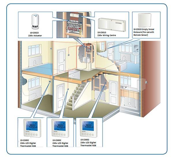
21 Typical UFH Installation Overview Page 21

22 Base 230v UFH Controls v 4-Zone Wiring Centre v Dial Thermostat NSB v 8-Zone Wiring Centre v LCD Digital Thermostat NSB v LCD Single Channel Time Clock v LCD Programmable Thermostat NSB Remote Sensor 4.7K for use with Dial / Tamper Proof thermostats only v Tamper Proof Thermostat NSB Empty Enclosure (for remote Sensor) v Electrothermic Actuator Head Page 22


23 Wireless UFH Controls Wireless 8-Zone UH8-RF Wiring Centre NeoAir Wireless Thermostat Wireless Programmable Thermostat c/w Receiver Boost - Neo / RF repeater Wireless Programmable Thermostat v Electrothermic Actuator Head Wireless Touchscreen Thermostat Page 23


 Thermostat (UH8 only) 10-23023 230v")


24 Premium 230v UFH Controls v 4-Zone UH4 Wiring Centre v TM1-V3 Single Channel Time Clock v 8-Zone UH8 Wiring Centre v TM4-TS 4-Channel Time Clock N 230v Dial (DS-SB) Thermostat (UH8 only) v Electrothermic Actuator Head N 230v Slimline Programmable Thermostat Remote Sensor (10k) N 230v Touchscreen Thermostat Empty Enclosure (for remote Sensor) Page 24

25 24v UFH Controls v 8-Zone Wiring Centre v Dial Thermostat NSB v LCD Single Channel Time Clock v LCD Digital Thermostat NSB Remote Sensor 4.7K for use with Dial / Tamper Proof thermostats only v LCD Programmable Thermostat NSB v Tamper Proof Thermostat NSB v Electrothermic Actuator Head Empty Enclosure (for remote Sensor) Page 25


 18-99999 neohub -")

26 Smart 230v UFH Controls Network control of your mains wired heating system from your Smartphone and Tablet v 8-Zone UH8 Wiring Centre v NeoStat Programmable Thermostat Example only Smartphone (not included) neohub - Neo System Gateway neoultra - Central Control v Electrothermic Actuator Head Page 26
27 FAQ / Trouble Shooting? As described in earlier sections, the UFH system operation is relatively straightforward. Hot water from the primary heat source (boiler) is blended with the return water from the UFH secondary circuit at the mixing valve and distributed, via the secondary UFH pump, to the distribution manifold and into a series of UFH loops/ circuits of pipe embedded with the floor. Normally, there is a room temperature control, which will open and close a single or series of actuators mounted on the manifold, or prior to the manifold (single zone), depending upon the room requirement. If one or all thermostats are calling for heat, there is a boiler interlock switch to energise the boiler The majority of problems are usually simple installation problems, relating to the wiring or plumbing, or design problems with regards to the limitations of UFH and its suitability for the purpose intended. In all cases where an electrical fault is reported it is always prudent to check the obvious before replacing components. Is there an electrical supply? Is it switched on? Are there any fuses that may have blown and need replacing? Are any components overloaded? Is everything wired correctly? Under no circumstances replace a fuse with a higher rating than stated for the piece of equipment. If the water arriving at the manifold (prior to entering the mixing valve) is either cold or below the design temperature, check: The boiler is firing The primary pump is fitted The primary pump is working The boiler is of adequate size The primary pipework is sufficiently sized The primary pumps are large enough Operating Problems? If a loop or loops fail to warm, when other zones are working correctly. General things to look for: Check that the corresponding manifold valves are open Check that there is a demand from the corresponding room thermostat and/or the thermal actuator is open on demand. There may be an air lock in the loop, which will require purging, either shut down all other loops by closing the valves at the manifold or turn down all other room thermostats. This will concentrate all pump pressure to the problem lip and may shift the air blockage. If all else fails the loop can be flushed through with high-pressure water following the instructions details in Filling, Venting and Pressure testing. If circulation is apparent but poor, it may be that the regulating control valve on the manifold required adjustment. Check that all pump isolating valves are fully open. The UFH / Room is not getting Warm? General things to look for. That the room thermostat fitted is calling for hear and that the valve has opened using the visual window on the actuator. That the room thermostat is connected to and communicating to the correct actuator(s). That the room thermostats are not operating in temperate set-back mode. That the floor temperature is correct as it enters the floor loops. Although typical design water temperatures are suggested through this guide, there is some element of a learning curve with UFH, as on some occasions the design water temperature may need to be raised after commissioning and once the system has been in operation during a heating season. That the primary flow and return connections are installed correctly and not crossed over at the UFH manifold. That the primary water temperature is not too low. This needs to be at least 15 C higher than the UFH system water temperature, especially when using a Pump Control Pack. That the high limit thermostat on the V5 Compact Control Pack is not set too low. That the lockshield valve on the V5 Compact Control Pack is set correctly. Thermal resistance of floor covering is not too high, as this could reduce the floor heat output. If the system is too noisy? General things to look for. There is no air in the system That all pipes are firmly clipped in place and that the manifold brackets are tight. That the UFH pump speed is not set too high. The excessive pressure from another circulator in the system is not interfering (hence the importance of having a primary bypass) Page 27
28 FAQ / Trouble Shooting? If the running costs are high? General things to look for. That the UFH system is correctly electrically connected to the boiler to prevent short cycling and to ensure that the boiler is not running when it is not required. That the room temperatures and thermostat settings are not too high (typical comfort temperatures are 20 C in living quarters and 18 C in bedrooms) For any open windows or draughts, it is not unknown for windows to be open in cold weather, as the internal comfort remains constant with thermostatic controls. That the boiler is running correctly. Has it been serviced and/or commissioned by an approved engineer. That the floor downward losses are high due to inadequate level of floor insulations. The design water temperature is not met? General things to look for. Check all control valves are correctly installed in their correct orientations and that any remote sensors are installed and located in suitable position. Check the temperature settings are as per design and adjust as necessary, depending on the water temperature control system used. Check the primary water temperature is not too low. This needs to be at least 15 degrees in excess of the UFH system temperature. The system is losing pressure? General thing to look for. If the system is losing pressure either during testing and or after the system has been filled, but the flooring has not been laid, simple visual manual checks around the manifold and along each look of pipe should identify the problem area. If there are no clear visual signs, each loop circuit may require a separate pressure test to identify the exact location. If the floor has been laid, identification of the fault can be traced through signs of a wet patch around the leak. Obviously to make the repair, the floor will have to be raised, in screed floors, excavated carefully in the centre of the wet patch. Any leaks on the manifold are generally due to the connection and any loose nuts and unions will require tightening. Repairs To make repairs to the pipe, follow the process below: Repairing the pipe: Isolate the damaged pipe loop at the manifold. Cut out the damaged section of pipe. Prepare both ends of pipe using pipe cutters. For MLC Pipe use a bevelling tool. On panel systems, remove a small section of the floating panel or fixed tracked panel, to accommodate the compression fittings. Slide the compression adaptor nut over each end of pipe together with olive on PEX pipes, prior to inserting the insert sleeve into each end. Offer both ends of pipe/inserts to the compression coupler and tighten both nuts. Ideally, the joint will require and inspection chamber in case further maintenance is required. However, in practice this is often not practical, and the fitting is wrapped in suitable tape before burying in the screed (ensure approval with the building inspector is ought prior to doing this) Pressure test the system again before laying the floor covering. Page 28
29 Guarantee & Warranty The guarantee period shall be 12 months from the date of delivery. During such period, the Company shall remedy any defects in the goods arising out of defective materials or workmanship provided that the Purchaser shall immediately give notice of such defects to the Company both verbally and in writing. After giving such notice, the Purchaser shall within 7 days return the defective goods any part thereof to the Company at the Purchaser s risk and expense. The company cannot guarantee the quality or use of any third party manufacturer s fittings with its own, however supplied. Warranty claims are subject to proof that the products have been correctly installed. Warranty does not cover any defect, damage or malfunction in the product which is due to: failure to comply in any respect with Multipipe installation guidelines, maintenance or operating instruction; faulty storage handling, repair, miss-use; neglect; accident; abuse; or general wear and tear. Failure as a result of the heat transfer fluid freezing within the pipe will not be covered by this warranty. During the warranty period, The Company shall replace or remedy any defects in the goods arising out of defective materials or workmanship, provided that the purchaser shall immediately give notice of such defects both verbally and in writing to The Company. Before any warranty can be provided, the original purchaser will be required to provide proof or purchase and any supporting information Renovo may need to conduct any investigation into alleged defect. Page 29
: 01245 227630 Midlands Office: 01245 850799 Technical: 01245 850799 Fax: 01245 698796")
30 Head Office: Unit 12, Great Hayes Business Park, Lower Burnham Road, Stow Maries, Chelmsford, CM3 6SQ Midlands Design and Estimating Office: Ladywood House, Ladywood Works, Leicester Rd, Lutterworth, Leicester LE17 4HD Sales (Head Office): Midlands Office: Technical: Fax:
MANIFOLDS & WATER TEMPERATURE CONTROL
 MANIFOLDS & WATER TEMPERATURE CONTROL Overview Water based underfloor heating (UFH) systems work by turning the entire floor into one large low temperature radiator which is heated via a network of pipes
L634 [56.49] X UNICLASS L ambiente. more than underfloor UNDERFLOOR HEATING TRADE PRICELIST
![L634 [56.49] X UNICLASS L ambiente. more than underfloor UNDERFLOOR HEATING TRADE PRICELIST](/thumbs/73/69438014.jpg "L634 [56.49] X UNICLASS L ambiente. more than underfloor UNDERFLOOR HEATING TRADE PRICELIST") L634 [56.49] X UNICLASS L75627 ambiente more than underfloor UNDERFLOOR HEATING TRADE PRICELIST 2016-17 003 KITCHEN / DINING 20 C 2463 W 001 LOUNGE 20 C 1381 W 006 UTILITY 18 C 611 W 005 HALL / CLOAK ROOM
L634 [56.49] X UNICLASS L75627 ambiente more than underfloor UNDERFLOOR HEATING TRADE PRICELIST 2016-17 003 KITCHEN / DINING 20 C 2463 W 001 LOUNGE 20 C 1381 W 006 UTILITY 18 C 611 W 005 HALL / CLOAK ROOM
Underfloor Heating. Solid floor Floating floor Suspended floor. Overlay. Ultra Flexible Underfloor Heating Pipe. Manifolds - All Floor Systems
 UNDERFLOOR HEATING The primary aim of the floor heating system is to create an even, uniform surface temperature across the entire floor area within the building in order to ensure a consistent comfort
T2 Wall Hung Radiator & UFH Manifolds
 T Wall Hung Radiator & UFH Manifolds T Topway LS Pre-Assembled Heating Manifold A range of nickel plated extruded brass manifolds pre-assembled for immediate installation for both radiator and underfloor
Product and installation manual. Underfloor Heating Composite Manifold
 Product and installation manual Composite Manifold Contents Introduction 2 Manifold Overview 3 Manifold Design 3 Manifold Dimensions 3 Manifold Installation 4-9 Pack Requirements 4 Required Tools 4 General
M-8100EP. Installation Guide ENGINEERED PLASTIC MANIFOLD SERIES. Introduction. A. Assemble Manifold Components
 Introduction The Pro Manifolds with Integrated adaptor are designed for use in Hydronic radiant panel heating and cooling applications. They are available in various sizes, configurations, and options
T2 Wall Hung Radiator & UFH Manifolds
 T Wall Hung Radiator & UFH Manifolds T Topway LS Pre-Assembled Heating Manifold A range of nickel plated extruded brass manifolds pre-assembled for immediate installation for both radiator and underfloor
Underfloor Heating Manifold Control Kit
 Installation and Maintenance Instructions Underfloor Heating Manifold Control Kit The UFH Manifold Control Kit provides temperature controlled mixed water to an underfloor heating system. Technical Specifications
Underfloor heating & cooling solutions by Wavin
 February 2010 UF428 Underfloor heating & cooling solutions by Wavin Composite Manifold Installation Guide FOR RESIDENTIAL AND LIGHT COMMERCIAL APPLICATIONS Usability, Versatility and Reliability Composite
LK Manifold RF. Design. Requirements. Documentation
 LK Manifold RF Design LK Manifold RF is made of stainless steel, the variants having 2 to 12 floor heating circuits. The manifold is delivered pre-mounted in brackets. The manifold has thermometers on
M Installation Guide. PRECISION Manifold Series. Introduction. A. Assemble Manifold Components
 Page 1 Introduction The M-8200 Precision Manifolds are designed for use in Hydronic radiant panel heating and cooling applications. They are available in various sizes, configurations, and options with
PLUMBING SYSTEMS PIPE & FITTINGS
 PIPE & FITTINGS MLCP MultiLayer Pipe & Fittings By combining PE-RT and aluminium, a new technologically advanced material is formed, providing security and safety. Our Multitubo systems MLCP is designed
LK Manifold Shunt VS2
 LK Manifold Shunt VS2 Design LK Manifold Shunt VS2 is a shunt unit with a two way control valve used in systems with a primary pump. The shunt unit is mountable from both the left and right of LK Manifolds.
FCU Floor Control Unit
 Fully assembled with integrated M3V Control Group including mixing valve and circulating pump and in-line high and low temperature Topway T2 FM manifold options with high and low temperature manifold options
Manifold Isolation Valves
 300 N. Opdyke Rd. Introduction The Stainless Manifolds are designed for use in Hydronic radiant panel heating and cooling applications. They are available in various sizes, configurations, and options
THERMOSTATIC INLINE CONTROL SHOWER VALVES Installation & aftercare instructions
 THERMOSTATIC INLINE CONTROL SHOWER VALVES Installation & aftercare instructions Please retain for future reference DUAL INLINE CONCEALED VALVE SV2204 / SV4404 / SV5504 / SV6604 SV7704 / SV8804 / SV9904
Solar Thermal. Grant Solar Pump Station Installation & Servicing Instructions
 Solar Thermal Grant Solar Pump Station Installation & Servicing Instructions Part No. DOC 96. Rev 02. October 2012 Important Note Important Note for Installers The Pump Station supplied with your Grant
THERMOSTATIC CONCENTRIC DUAL CONTROL SHOWER VALVES Installation & aftercare instructions
 THERMOSTATIC CONCENTRIC DUAL CONTROL SHOWER VALVES Installation & aftercare instructions Please retain for future reference EXPOSED CONCENTRIC VALVE SV2201 / SV4401 / SV5501 / SV6601 SV7701 / SV8801 /
PLUMBING SYSTEMS PIPE & FITTINGS
 PIPE & FITTINGS MLCP MultiLayer Pipe & Fittings Our MLCP product offering By combining PE-RT and aluminium, a new technologically advanced material is formed, providing security and safety. Our Multitubo
SYSTEM KAN-therm. Underfloor heating. Comfort and efficiency TECHNOLOGY OF SUCCESS ISO 9001
 SYSTEM KAN-therm Underfloor heating Comfort and efficiency TECHNOLOGY OF SUCCESS ISO 9001 The underfloor heating of System KAN-therm - pipes and pipe accessories KAN-therm pipe PE-RT with EVOH layer for
Underfloor heating. installation manual. Nu-Heat v19. For more information visit UNDERFLOOR HEATING SOLAR THERMAL HEAT PUMPS
 Underfloor heating installation manual v9 Nu-Heat 207 UNDERFLOOR HEATING HEAT PUMPS SOLAR THERMAL For more information visit www.nu-heat.co.uk working with you before, during & after your project Nu-Heat
LK Manifold RF. Design. Requirements
 LK Manifold RF Design LK Manifold RF is made of stainless steel, the variants having 1 to 12 floor heating circuits. The manifold is delivered pre-mounted in brackets. The manifold has thermometers on
MrPEX 1 ¼ Stainless Steel Manifold. Installation Guide
 MrPEX 1 ¼ Stainless Steel Manifold Installation Guide Design MrPEX 1 ¼ Stainless Steel Manifold is made from high quality stainless steel, and is offered in 2 through 12 loop configurations. The manifold
MrPEX 1 ½ " Brass Manifold Installation Guide
 MrPEX 1 ½ " Brass Manifold Installation Guide Design MrPEX 1 ½" Brass Manifold is made from high quality alloy extruded and chrome plated after machining, and is offered in 2 through 12 loop configurations.
plumbaseindustrial.co.uk SYSTEMS PRICE GUIDE Multilayer Pipes and Fittings. HIU's, Meters & Valves
 SYSTEMS PRICE GUIDE 2018 JANUARY 2018 Multilayer Pipes and Fittings HIU's, Meters & Valves Underfloor Heating - Domestic, Commercial, Electric Pre-Insulated Pipe Systems WWW.MULTIPIPE.CO.UK plumbaseindustrial.co.uk
MMR25. Instruction Manual for Operation & Maintenance. IB International. Ph:
 MMR25 Instruction Manual for Operation & Maintenance IB International www.ibinternational.com.au Ph: 07 3348 8300 Contents Introduction... 2 Identification Data... 3 Machine Controls & Components... 3
Engineered Water Solutions Installation and Commissioning Instructions FCU Floor Control Unit
 Engineered Water Solutions Installation and Commissioning Instructions FCU Floor Control Unit Robust pre-assembled M3V control group constructed from PP composite with four swivel joints for connection
Adjustable Angled Incline Conveyor Owners Manual with Operating Instructions
 Adjustable Angled Incline Conveyor Owners Manual with Operating Instructions Revision 012211 Table of Contents Basic Conveyor Features 3 Getting Started 4 Setting Up the Incline Conveyor 5 Belt Removal
FOR HEATING & PLUMBING SYSTEMS
 Quality Plastics Ltd. Pushfit Option Compression Option MANIFOLD SYSTEM ADVANTAGES: Central Control. Eliminates variations in pressure and flow. Individual pipes to each outlet allowing separate shut-off
Installation, Operating, Maintenance and Safety Instructions for CW332 Pressurised water system for boats 24 volt d.c.
 24V DC-CW332 DOC531/11 Installation, Operating, Maintenance and Safety Instructions for CW332 Pressurised water system for boats 24 volt d.c. To obtain the best performance from your Pressurised water
Snow Melt EN_US_2014_V2.indb 171 2/7/ :18:52 AM
 171 Viega snow melting systems are complete hydronic solutions for residential, commercial and industrial applications. All it takes is ViegaPEX Barrier tubing installed in a concrete slab and the proper
3.1 DISPENSER BLACK SHADOW SERIES. Tools Needed for Mounting SCS Dispenser Hammer
 SCS 2 BLACK SHADOW SERIES 3.1 DISPENSER ALWAYS OBSERVE PRODUCT SAFETY AND HANDLING INSTRUCTIONS. ALWAYS DIRECT DISCHARGE AWAY FROM YOU or other persons. ALWAYS DISPENSE CLEANERS AND CHEMICALS AS DIRECTED
Part No: Genuine Mira Accessories
 Bar Valve Fixing Kit Part No: 1663.017 Genuine Mira Accessories 1 Introduction Please take time to read this guide thoroughly, having done so, keep it handy for future reference. This Fixing Kit has been
Underfloor Heating Manifold Kits
 Installation and Maintenance Instructions Reliance Worldwide Corporation (UK) Ltd Worcester Road, Evesham, Worcester, WR RA, UK Underfloor Heating Manifold Kits Tel: + (0)86 7 00 Fax: + (0)89 7 0 www.rwc.co.uk
For assistance call T&M. Tubing and manifolds. installation guide
 For assistance call 1.877.338.5493 1 06.17 T&M Tubing and manifolds installation guide 2 Table of contents For assistance call 1.877.338.5493 3 Manifold diagram Page 4 Manifold installation Page 5 Tubing-to-manifold
Tools Needed for Mounting Cleá Filling Station
 ALWAYS OBSERVE PRODUCT SAFETY AND HANDLING INSTRUCTIONS. ALWAYS DIRECT DISCHARGE AWAY FROM YOU or other persons. ALWAYS DISPENSE CLEANERS AND CHEMICALS AS DIRECTED ON THE LABEL. ALWAYS DISPENSE INTO APPROVED
Technical Installation Manual
 Lighting Step and Aisle Safety Lighting Technical Installation Manual 1 Contents Page 3 Tools required 4 Installation detail & planning 5 Adhesives, silicone & crimps 6 General cinema layout 7 Basic wiring
GTFLOW EXTENSION MANIFOLD ASSEMBLY INSTRUCTIONS
 Page 1 of 5 Step 1: ASSEMBLE THE MAIN MANIFOLD AND MANIFOLD EXTENSION KIT First and very important step is to properly connect the main manifold and the manifold extension kit together by using the two
Composite PEX-AL-PEX Tubing
 04/01/11 page 1.1 Composite PEX-AL-PEX Tubing List Per Foot 40190F ½ Composite Tubing x 200.62 40190 ½ Composite Tubing x 250.62 40190A ½ Composite Tubing x 300.62 40190B ½ Composite Tubing x 1000.62 40192
LK Shunt Cabinet VS2, Shunt Cabinet VS2 Prefab
 LK Shunt Cabinet VS2, Shunt Cabinet VS2 Prefab Design LK Shunt Cabinet VS2 The LK Shunt Cabinet VS2 is designed to be used when you wish to hide the LK Manifold RF and LK Manifold Shunt VS2. The cabinet
20 TONNE HYDRAULIC PRESS MODEL NO: CSA20FBT
 20 TONNE HYDRAULIC PRESS MODEL NO: CSA20FBT PART NO: 7614058 OPERATION & MAINTENANCE INSTRUCTIONS WARNING: Read these instructions before using the press GC0516 INTRODUCTION Thank you for purchasing this
Installation Guide Rollerdor RD55 Econ Roller Garage Door
 Installation Guide Rollerdor RD55 Econ Roller Garage Door 1 Finished door Rollerdor RD55 Econ Roller Garage Door CHECKLIST & COMPONENTS EQUIPMENT REQUIRED 2 x Step ladders or hop ups Spirit level Tape
VANDAL RESISTANT FITTINGS VR105, VR125, VR145 (VR106, VR115 Export only) PRODUCT MANUAL IMPORTANT
 PRODUCT MANUAL IMPORTANT") VANDAL RESISTANT FITTINGS VR105, VR125, VR145 (VR106, VR115 Export only) PRODUCT MANUAL SHOWER FITTINGS IMPORTANT Installer: This Manual is the property of the customer and must be retained with the product
VANDAL RESISTANT FITTINGS VR105, VR125, VR145 (VR106, VR115 Export only) PRODUCT MANUAL SHOWER FITTINGS IMPORTANT Installer: This Manual is the property of the customer and must be retained with the product
METERING VALVE 2" STEM GUIDED
 2" STEM GUIDED All Rights Reserved. All contents of this publication including illustrations are believed to be reliable. And while efforts have been made to ensure their accuracy, they are not to be construed
Scale Feeder Manifold Water Filtration System Instruction Manual
 3M TM Water Filtration Products Scale Feeder Manifold Water Filtration System Instruction Manual For SF1XX High Flow Series Water Filtration Systems Installer: Please leave this manual with owner/operator.
Dual Port Manifold Water Filtration Systems Instruction Manual
 M TM Water Filtration Products Dual Port Manifold Water Filtration Systems Instruction Manual For DP1XX, DP2XX and DPXX High Flow Series Water Filtration Systems Installer: Please leave this manual with
Hot and Cold Plumbing Manifold Systems
 Hot and Cold Plumbing Manifold Systems Hot and Cold Manifold Overview By using an Emmeti manifold system in a point to point plumbing configuration you can greatly reduce the number of joints in your system,
6 Litre Oil-Less Air Compressor
 Operator s Manual 6 Litre Oil-Less Air Compressor WARNING! Before using this appliance, read the Operator s manual and follow all its safety rules and instructions. SPECIFICATION HWKAC1 1.1 kw / 1.5 HP
HOT WASHER MODEL NO: KING 125 OPERATION & MAINTENANCE INSTRUCTIONS PART NO: LS1009
 HOT WASHER MODEL NO: KING 125 PART NO: 7320170 OPERATION & MAINTENANCE INSTRUCTIONS LS1009 INTRODUCTION Thank you for purchasing this Hot Washer. This machine is a portable, high pressure power washer,
APT14 Automatic Pump Trap Installation and Maintenance Instructions
 6120250/7 IM-P612-04 ST Issue 7 APT14 Automatic Pump Trap Installation and Maintenance Instructions 1 Product information 2 Operation 3 Installation Closed loop steam systems only 4 Commissioning 5 Maintenance
Model 6518FR. NOTE TO INSTALLER: Please leave this information with the Maintenance Department. LIMITED WARRANTY
 INSTALLATION, OPERATION & MAINTENANCE INSTRUCTIONS 1455 Kleppe Lane Sparks, NV 89431-6467 (775) 359-4712 Fax (775) 359-7424 E-mail: haws@hawsco.com website: www.hawsco.com Model 6518FR No. 2077777(21)
PRE-PLUMBED SEWAGE SYSTEM
 PRE-PLUMBED SEWAGE SYSTEM Zoeller is a registered trademark of Zoeller Co. All Rights Reserved. MODEL #1910-0009 Español p. 13 ATTACH YOUR RECEIPT HERE Serial Number Purchase Date Questions, problems,
Dual/Triple Manifold Water Filtration Systems Instruction Manual
 3M TM Water Filtration Products Dual/Triple Manifold Water Filtration Systems Instruction Manual High Flow Series Water Filtration Systems Installer: Please leave this manual with owner/operator. 3M Water
Heating Manifold Systems
 Bathroom thermostat and remote sensor Engineered Water Solutions Product Focus Topway T2 Manifolds T3 Controller Control T EWC-1 Wiring Box Zone Controls Alpert UFH Pipe Heating Manifold Systems High Temperature
Acura TMV3 Bath Filler AC50010CP and AC50020CP
 Acura TMV3 Bath Filler AC50010CP and AC50020CP Installation and Maintenance Instructions In this procedure document we have endeavoured to make the information as accurate as possible. We cannot accept
Rotary Folding Hoists
 Rotary Folding Hoists Owner s Manual To suit models: Rotary 400TM Rotary 450TM Rotary 500TM Rotary 400TM Plus Rotary 450TM Plus Rotary 500TM Plus Unpacking Introductionthe Hoist Congratulations Congratulations
Key Installation Points. Table of Contents
 Installation Guide Key Installation Points Table of Contents All pipe sizes in this guide are internal diameter (DN) We recommend PE-X pipe NOT copper pipe Check pipes sizes For domestic installations
INDOOR CLIMATE SOLUTIONS PRODUCT CATALOG Uponor Radiant Heating/Cooling
 INDOOR CLIMATE SOLUTIONS PRODUCT CATALOG 2012 Uponor Radiant Heating/Cooling Uponor Radiant Heating/Cooling > List of content List of content Abbreviations 4 Uponor Renovationsystem Minitec Uponor Minitec
Product Manual PS3900 / PS4600 / PS7000 / PS15000 / BF1600 / BF1900 / BF2600 / BF
 WG Product Manual PS3900 / PS4600 / PS7000 / PS15000 / BF1600 / BF1900 / BF2600 / BF3800 1.330.274.8317 www.atlanticwatergardens.com Table of Contents Pond Volume... 2 Surface Area... 3 Streambed Construction...
www. hydrofuse.com Installation Manual Fertilizer Machine V1.3
 www. hydrofuse.com Installation Manual Fertilizer Machine V1.3 Introduction Hydrofuse is a new concept in fertilizing that works with existing irrigation (sprinkler) systems and automatically dispenses
Wall Hung Radiator Systems. Wall Hung Radiator Systems
 Wall Hung Radiator Manifold Overview Manifold systems are widely used with underfloor heating and this same principle can be applied to wall hung radiators. By using an Emmeti manifold system in a point
ALWAYS DISCONNECT DISPENSER FROM WATER SOURCE WHEN DISPENSER IS NOT IN USE.
 1060GAPRF With dilution selector 1060GAP OVERVIEW DEMA S MPD is a multiple product and dilution dispenser designed for use with SafeLink closed loop inserts. With its innovative patent pending QuickDock
CHECKLIST & COMPONENTS
 Eclipse Compact www.rollershuttercompany.com Tel 0800 6444121 55mm Roller Garage Doors CHECKLIST & COMPONENTS EQUIPMENT REQUIRED 2 x Step ladders or hop ups Spirit level Tape measure Power drill 10mm A/F
Hydraulic Motorcycle Lift. Model CML3 & CML3 AIR Part No: ASSEMBLY & OPERATING INSTRUCTIONS 0212
 Hydraulic Motorcycle Lift. Model CML3 & CML3 AIR Part No: 7610143 ASSEMBLY & OPERATING INSTRUCTIONS 0212 DO NOT ENTER UNDER THE PLATFORM UNLESS IT IS MECHANICALLY LOCKED (see instructions) DO NOT EXCEED
Electric Diesel Pump EDP/12, EDP/24
 INSTRUCTION MANUAL Electric Diesel Pump EDP/1, EDP/4 S1940, Rev C Congratulations on purchase of this World Class Electric Diesel Pump! Portable Diesel transfer pumps designed for everyday use in Agricultural,
BOLT-ON AND WELD-ON FLUSH FLOOR SLIDEOUT SYSTEMS OPERATION AND SERVICE MANUAL
 BOLT-ON AND WELD-ON FLUSH FLOOR SLIDEOUT SYSTEMS OPERATION AND SERVICE MANUAL TABLE OF CONTENTS SYSTEM...... Warning........ Description...... Prior to Operation OPERATION... Main Components... Mechanical...
ECONOPLATE BV SERIES HOT WATER SERVICE PACKAGED HEAT EXCHANGERS WITH THERMAL STORES
 ECONOPLATE BV SERIES HOT WATER SERVICE PACKAGED HEAT EXCHANGERS WITH THERMAL STORES TECHNICAL AND INSTALLATION DOCUMENTATION STOKVIS ENERGY SYSTEMS UNIT 34 CENTRAL PARK ESTATE 34 CENTRAL PARK ESTATE WEST
TS Series. MultiStage Centrifugal Pump Instruction Manual. Walrus America Inc. ISO 9001 Certified
 TS Series MultiStage Centrifugal Pump Instruction Manual 234867 ISO 9001 Certified Walrus America Inc EC Declaration of Conformity Manufacturer: Walrus Pump Co., Ltd. Address: No. 83-14, Dapiantou, Sanjhih
Manifolds Controls Pipe Accessories
 Engineered Water Solutions Wall Hung Radiator Heating Systems Manifolds Controls Pipe Accessories www.emmeti.co.uk Company Overview The Group Our parent company Emmeti S.p.A. was founded in 97, initially
Safety, Operation and Maintenance Instructions For Long & Short Nose Upholstery Air Stapler (NS10 & NS11)
") Safety, Operation and Maintenance Instructions For Long & Short Nose Upholstery Air Stapler (NS10 & NS11) Important: Drop 3 drops of oil into the stapler air inlet BEFORE first use. See page 2. Please
Safety, Operation and Maintenance Instructions For Long & Short Nose Upholstery Air Stapler (NS10 & NS11) Important: Drop 3 drops of oil into the stapler air inlet BEFORE first use. See page 2. Please
Installation Guide Rollerdor RD55 Econ Roller Garage Door
 Installation Guide Rollerdor RD55 Econ Roller Garage Door 1 Finished door Rollerdor RD55 Econ Roller Garage Door CHECKLIST & COMPONENTS EQUIPMENT REQUIRED 2 x Step ladders or hop ups Spirit level Tape
CIRCO5SolarCirculationUnit
 TECHNICAL INFORMATION / INSTALLATION MANUAL CIRCO5SolarCirculationUnit Wagner& Co CIRCO 5 Solar Circulation Unit the reliable pump station for efficient circulation of the heating fluid in combination
CT3202.0_01 EN February 2018
 UNDERFLOOR HEATING / RADIATOR HEATING COMPACT BRASS MODULAR MANIFOLDS (centre distance 37 mm) CT3202.0_01 EN February 2018 o o o Super compact: e.g. 11 ways (version code 3211.06.10) in just 60 cm; Insertion
MrPEX 1 ¼ Stainless Steel Manifold Installation Guide
 MrPEX 1 ¼ Stainless Steel Manifold Installation Guide Design MrPEX 1 1/4 Stainless Steel Manifold is made from high quality stainless steel, and is offered in 2 through 12 loop configurations. The manifold
Installation Guide Rollerdor RD77 Econ Roller Garage Door
 Installation Guide Rollerdor RD77 Econ Roller Garage Door 1 Finished door Rollerdor RD77 Econ Roller Garage Door CHECKLIST & COMPONENTS EQUIPMENT REQUIRED 2 x Step ladders or hop ups Spirit level Tape
ETP-5E & ETP-10E ECO-TECH PLUS ELECTRIC CONVECTION STEAMER PARTS AND SERVICE MANUAL
 ETP-5E & ETP-10E ECO-TECH PLUS ELECTRIC CONVECTION STEAMER PARTS AND SERVICE MANUAL EFFECTIVE JANUARY 10, 2018 Superseding All Previous Parts Lists. The Company reserves the right to make substitution
Installation must be in Accordance with AS/NZS
 Installation must be in Accordance with AS/NZS 3500.1. Contents 5 Step Easy Install... 3 Installation Requirements... 3 Cistern Service Access Options... 4 Button Service Access Options... 5 Installing
TL4076 Top 5 Tips Get to know your TL4076
 TL4076 Top 5 Tips Get to know your TL4076 Thermal Break with Teflon liner (behind fan) Hot End Assembly Fan Heat Block Extruder with toothed gear(brass) and idler (steel) Filament Guide Tube Nozzle Cable
INSTALLATION AND OPERATION MANUAL
 INSTALLATION AND OPERATION MANUAL Models S120U & S240U Read all instructions before assembling or using the SunHeater system. Retain this manual for future use. TABLE OF CONTENTS Important Safety Information...2
CRD600 Automatic Fitting Inserter
 CRD600 Automatic Fitting Inserter OPERATIONS MANUAL VERSION 2.3 LAST EDITED 12.07.2018 cleanroomdevices.com 1 Table of Contents Title Page.. 1 Table of Contents. 2 1.0 General Product & Safety Information...3
CRD610 Automatic Fitting Inserter
 CRD610 Automatic Fitting Inserter OPERATIONS MANUAL VERSION 1.2 LAST EDITED 12.12.2018 cleanroomdevices.com 1 Table of Contents Title Page. 1 Table of Contents...2 1.0 General Product & Safety Information....3
Hydraulics. Part B, Section 1. This section covers the following unit configurations. 3700V
 Part B, Section 1 Model Voltage Pump Manifold Control This section covers the following unit configurations. 3500V 3700V 3860 3890 3930 3960 All Piston (D) 4-Port (A) 6-Port (B or C) 2-Port (S or T) Vista
OWNER S OPERATING MANUAL
 OWNER S OPERATING MANUAL MIG 100 GASLESS WELDER TABLE OF CONTENTS Page Safety instructions 3-4 MIG Welders 5 Welder Information 5 Gasless welder set up 6 Operation 6-10 Troubleshooting Guide 11-12 Spare
INSTRUCTION MANUAL. Direct Drive Air Compressor 2320, REV A. 1.
 INSTRUCTION MANUAL 2320, REV A Direct Drive Air Compressor CONSTRUCTION DUAL MATERIAL CONSTRUCTION i) The cylinder block is made up of cast iron that prevents wear & tear thus imparting longevity to the
LABOUR ESTIMATE GUIDE
 INSTALLATION INSTRUCTIONS FOR 2001-2005 Audi A4 1.8T These instructions are applicable to vehicles equipped with either manual or automatic transmissions Thank you for choosing to purchase a Carbonio Intake
CLEAN ROOM DEVICES, LLC "WHERE TUBING AND FITTINGS COME TOGETHER"
 CLEAN ROOM DEVICES, LLC "WHERE TUBING AND FITTINGS COME TOGETHER" CRD600 Automatic Fitting Inserter OPERATIONS MANUAL VERSION 2.1 LAST EDITED 7.25.14 DOCUMENT NUMBER 001 cleanroomdevices.com 1 Table of
Compact Security FloodLight
 MAL615 Instructs.qxd 1/9/05 12:18 PM Page 3 Compact Security FloodLight Installation and Operation Instructions MAL615 (Series 5) Introduction The Arlec MAL615 Movement Activated Sensor Light is a compact
Table of Contents Introduction 3 Chapter 2: Operation 4 Chapter 3: Components 5 Chapter 4: Specifications 8
 Table of Contents Introduction 3 Application 3 Chapter 2: Operation 4 Manifold Function 4 Chapter 3: Components 5 Required Parts 5 Manifold without Actuators without Pressure Bypass Kit 5 Pump Kit (QHMPK_)
PRODUCT OPERATING MANUAL
 PRODUCT OPERATING MANUAL PANBLAST TM CS37 SUCTION BLAST CABINET Manual Number: ZVP PC 0069 00 SECTION 1. GENERAL INFORMATION 2. ASSEMBLY & INSTALLATION INSTRUCTIONS 3. OPERATING INSTRUCTIONS 4. MAINTENANCE
Full Flow Drinking Water System Model: 3MFF100
 Installation and Operating Instructions For Full Flow Drinking Water System Model: 3MFF100 System tested and Certified by NSF International against NSF/ANSI Standard 42 and 53 for the reduction of the
APT10-2 Automatic Pump Trap
 6120050/3 IM-P612-18 ST Issue 3 APT10-2 Automatic Pump Trap Installation and Maintenance Instructions 1. General safety information 2. Product information 3. Installation Closed loop steam systems only
MSC Manifolds - DIN for Steam Distribution and Condensate Collection Installation and Maintenance Instructions
 1170650/3 IM-P117-17 ST Issue 3 MSC Manifolds - DIN for Steam Distribution and Condensate Collection Installation and Maintenance Instructions 1 General safety information 2 General product information
BOLT TENSIONERS. carefully before use and retain it for reference.
 BOLT TENSIONERS This manual contains IMPORTANT WARNINGS, CAUTIONS and other instructions. Read and understand the instructions manual carefully before use and retain it for reference. TORCUP MIDDLE EAST
To the Fitter: Ensure all relevant personnel read the points listed below and that a copy is passed on to the end user.
 WATERMASTER SYSTEM Read carefully before installation and use. To the Fitter: Ensure all relevant personnel read the points listed below and that a copy is passed on to the end user. To the User: Read
Rehau easy heat domestic heating system parts list EN ENERGY EFFICIENCY. Building Solutions Automotive Industriy
 ENERGY EFFICIENCY Rehau easy heat domestic heating system parts list 890.617 EN Valid from March 2014 Subject to technical alterations www.rehau.co.uk/easyheat Building Solutions Automotive Industriy Rehau
Service Manual Air Tech Second Stage
 Service Manual Air Tech Second Stage Copyright 2002, Cressi-sub Revised 3/2002 2 Air Tech Second Stage Service Manual Contents BEFORE STARTING... 3 DISASSEMBLY... 3 PARTS CLEANING AND LUBRICATION... 9
INSTRS30709 rev 1 02/10/09 Page 1
 Bianco Rainsaver MK3 Installation and Operating Instructions INSTRS30709 rev 1 02/10/09 Page 1 Bianco Rainsaver MK3 Installation and Operating Instructions 1. Introduction: The Bianco Rainsaver MK3 is
1901 Thermostatic Shower Mixer
 1901 Thermostatic Shower Mixer (Universal Valve with Adjustable Riser, Surface Mounted Valve with Rigid Riser or Recessed Valve with Fixed Head) Fitting Instructions & Contents List Before starting any
Operation and Maintenance Instructions
 Hydratight Limited Bentley Road South Darlaston West Midlands WS10 8LQ United Kingdom Tel: +44 121 50 50 600 Fax: +44 121 50 50 800 E-mail: enquiry@hydratight.com Website: www.hydratight.com TOP COLLAR
ONBOARD AIR HOOKUP KIT
 ONBOARD AIR HOOKUP KIT PART NO. 20052 (30 amp - 110PSI on, 150PSI off) PART NO. 20053 (30 amp - 85PSI on, 105 PSI off) PART NO. 20055 (30 amp - 90 PSI on, 120 PSI off) IMPORTANT: It is essential that you